

Page 1
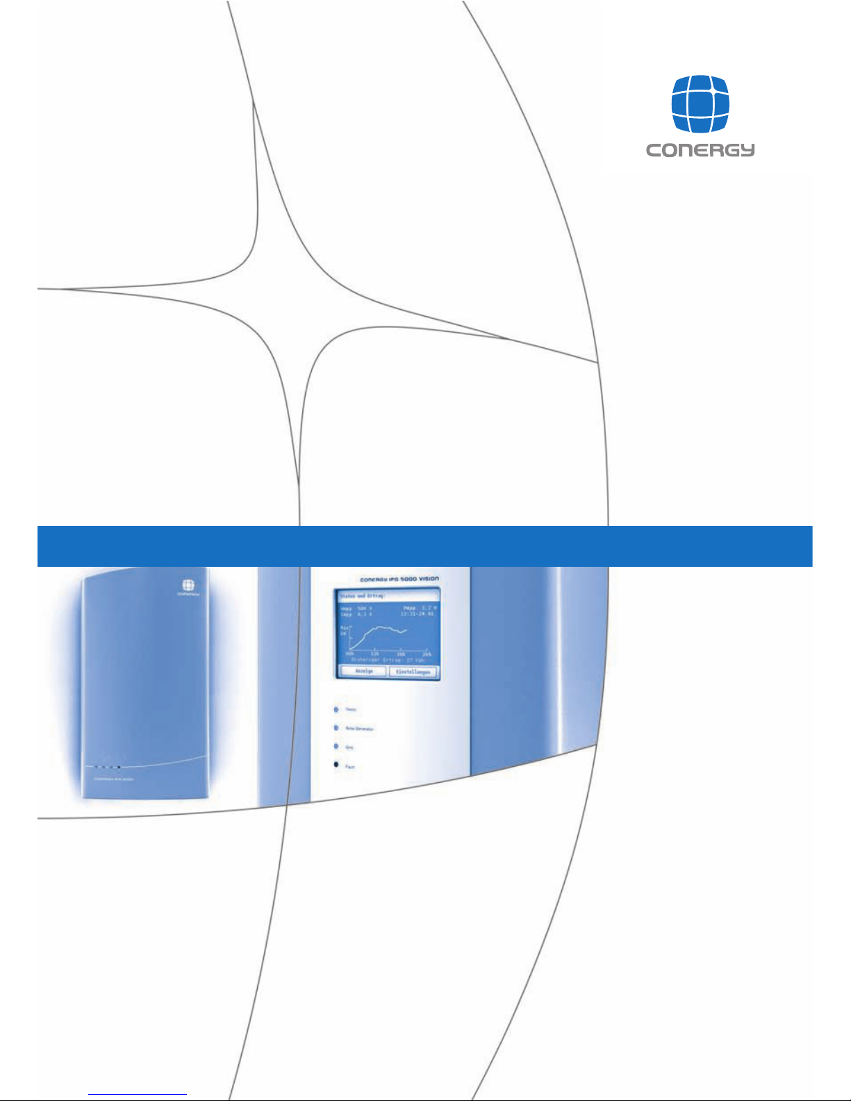
Conergy IPG string inverter series
Operating manual
Page 2

C o n e r g y IPG s t r in g in v e r t e r s e r ie s Instruc tion m anual 1
Ta b le o f c o n t e n t s
ENGHLISH
Ta b le o f c o n t e n t s
1Introduction 3
1.1 Short description 3
1.2 Additional products 4
1.3 User group 4
1.4 Signposts 5
1.5 Environmental information 5
1.6 Manufacturer information 6
1.7 Standards and technical directives 6
2 Safety 9
2.1 Intended use 9
2.2 Responsibilities of the owner/operator 9
2.3 Basic safety instructions 10
2.4 Warnings 11
3 Pr o d u c t d e s c r ip t io n 13
3.1 General information on photovoltaic systems 13
3.2 Block diagram 15
3.3 Functions 17
4 C o n e r g y IP G s t r in g v is io n inv e r t e r s e r ie s 19
5 Tr a n s p o r t a n d in s t a lla t io n 2 5
5.1 Included in delivery 25
5.2 Transportation 25
5.3 Installation 26
5.3.1 Prerequisites for the installation location 26
5.3.2 Wall mounting 30
Page 3

2 C o n e r g y IP G s t r in g in v e r t e r s e r ie s Instruc tion m an u al
Ta b le o f c o n t e n t s
ENGLISH
6 In s t a lla t io n a n d c o m m is s io n ing 3 3
6.1 Basic safety instructions 33
6.2 Preparation for installation 34
6.3 Connections 35
6.4 Connecting the mains cable 36
6.5 Connecting the solar system 40
6.6 Connecting the Conergy SunReader: 44
6.7 Connecting the 230- V power supply 45
6.8 Connecting Easyconnect 45
6.9 Connecting further string inverters 46
6.10 Connecting the terminator 46
6.11 Commissioning 47
7 Tr o u b le s h o o t in g 4 9
7.1 LED indicator fault messages 50
7.2 Fault warnings on the display 52
8 Re m o v a l 5 5
9 A p p e n d ix 5 7
9.1 Specifications 57
9.2 Index 59
Page 4

C o n e r g y IP G s t r in g in v e r t e r s e r ie s Instruction m anual 3
1 In t r o d u c t io n
ENGLISH
1Introduction
1.1 Short description
The string inverters of the Conergy IPG string inverter series
convert the direct current from the solar power system to
grid-compatible alternating current and supply this to the
public power grid. The string inverters of the Conergy IPG
series are transformerless units for single-phase power feed
to the grid.
This instruction manual relates to the string inverters of the
Conergy IPG series:
| Conergy IPG 4000 vision string inverter,
| Conergy IPG 4000 string inverter,
| Conergy IPG 5000 vision string inverter,
| Conergy IPG 5000 string inverter,
The designation "vision" represents the product version with
a display. The number represents the performance level,
corresponding to the nominal DC input power of 4,000 or
5,000 Wp.
The string inverters belong to the Conergy IPG string inverter
series product group, which in turn is part of the Conergy IPG
series (IPG = Inverter Power on Grid).
Page 5

4 Instruction m anual C o n e r g y IPG s t r in g in v e r t e r s e r ie s
1 In t r o d u c t io n
ENGLISH
1.2 Additional products
String inverters of the Conergy IPG series can optimally be
used with the Conergy IPG easyconnect generator junction
box. These devices are designed to work together and allow
for simple, time-saving installation. Conergy IPG series string
inverters and the Conergy IPG easyconnect are connected to
one another by means of prepared connections. The Conergy
IPG easyconnect generator junction boxes also offer, for
example, integrated lightning protection and automatic
DC disconnection.
String inverters of the Conergy IPG series can also optimally
be used with the internet-based Conergy SunReader
monitoring system. If you have already opted for the
Conergy IPG easyconnect generator junction box, Conergy
has already integrated the Conergy SunReader into the
individual monitoring system components.
With the help of the Conergy IPG sizer system
dimensioning program you can determine the optimum
combination of the solar power system with the Conergy
inverters.
You can find further information at:
| www.conergy.com
| www.sunreader.de
1.3 User group
This instruction manual is intended for an electrical specialist
appointed by the owner/operator. Basic knowledge of
electrics and electronics is necessary for the monitoring of
the inverter by means of the LED indicators or display.
Page 6
C o n e r g y IP G s t r in g in v e r t e r s e r ie s Instruction m anual 5
1 In t r o d u c t io n
ENGLISH
1.4 Signposts
The following aids will help orientation when using this
instruction manual:
Headers The headers display the heading of the current chapter.
Footers The footers display the name of the product, the name of the
document, and the page number.
Te x t m a r k u p s The wording of the LED indicators and the connections are
shown in bold. Item numbers are shown in the form (1) and
(2). Display messages are shown in a di f f er ent f ont . The
names of companies other than Conergy are shown in italics.
Symbols
1.5 Environmental information
The Conergy IPG series string inverters are made from
materials, almost all of which can be used again through raw
materials recycling. The device, its accessories, and its
packaging should therefore be recycled in an environmentally
responsible manner.
Denotes the start of an operation with a description of its
objective.
Individually numbered steps follow, which may be
interspersed with background information, illustrations, or
warnings.
Denotes background and additional information for
operational procedures.
Page 7

6 Instruction m anual C o n e r g y IPG s t r in g in v e r t e r s e r ie s
1 In t r o d u c t io n
ENGLISH
1.6 Manufacturer information
Manufacturer Conergy AG
www.conergy.com
Copyright information All rights to this document are reserved by the product
manufacturer (publisher). The document may not be
reproduced or passed on as a whole or in part without the
express written consent of the publisher. All illustrations,
drawings and other integrated media are subject to
copyright. The manufacturer reserves the right to make
technical modifications to the product.
Conergy AG, 2006
1.7 Standards and technical directives
The string inverters of the Conergy IPG string inverter series
comply with the following standards and directives:
| 89/336/EEC: Council Directive on the approximation of the
laws of Member States relating to electromagnetic
compatibility (amended by 93/97/EEC)
| 73/23/EEC: Council Directive on the approximation of the
laws of Member States relating to electrical equipment for
use within certain voltage limits (amended by 93/68/EEC)
| Electromagnetic Compatibility (EMC) Generic standards –
Immunity for industrial environments (IEC 61000-6-2: 1999,
mod.); German version EN 61000-6-2: 2001
| Electromagnetic Compatibility (EMC) Generic standards –
Emission standard for residential, commercial and light
industrial environments (IEC 61000-6-3: 1996, mod.);
German version EN 61000-6-3:2001 + A11: 2004
| Electromagnetic Compatibility (EMC); Limits for harmonic
current emissions (equipment input current ≤ 16 A per
phase) (IEC 61000-3-2: 2000, mod.); German version EN
61000-3-2: 2000
| Electromagnetic Compatibility (EMC); Limits - Limitation of
voltage changes, voltage fluctuations and flicker in public
low-voltage supply systems, for equipment with rated
current 16 A per phase and not subject to conditional
connection (IEC 61000-3-3: 1994 + A1: 2001 + A2: 2005);
German version EN 61000-3-3:1995 + A1: 2001 + A2: 2005
Page 8
C o n e r g y IP G s t r in g in v e r t e r s e r ie s Instruction m anual 7
1 In t r o d u c t io n
ENGLISH
| Electronic equipment for use in power installations
(IEC 62103: 2003); German version EN 50178: 1997
| Safety of power converters for use in photovoltaic power
systems – Part 1 – General requirements (IEC 62109-1:
2005)
| Safety of power converters for use in photovoltaic power
systems – Part 2 – Particular requirements for inverters (IEC
62109-2: 2005)
| Information technology equipment - Safety - Part 1:
General requirements (IEC 60950-1:2005-12)
| Automatic disconnection device between a generator and
the public low-voltage grid; DIN VDE 0126-1-1
| Guidelines of the VDEW (German Electricity Association)
governing the parallel operation of in-plant generating
systems with the low-voltage grid of the power supply
company
Please note that the above legal regulations may have been
modified since completion of this instruction manual.
Please also note that countries outside the Federal Republic
of Germany may have their own national directives, laws and
safety regulations.
Page 9

8 Instruction m anual C o n e r g y IPG s t r in g in v e r t e r s e r ie s
1 In t r o d u c t io n
ENGLISH
Page 10

C o n e r g y IP G s t r in g in v e r t e r s e r ie s Instruction m anual 9
2 Sa fe t y
ENGLISH
2 Safety
2.1 Intended use
String inverters of the Conergy IPG Series are designed
exclusively for the conversion of direct current from solar
modules to alternating current. Any other use is deemed not
to be as intended.
The inverter may only be installed within acceptable
environmental conditions.
Intended use also includes compliance with the
specifications of this instruction manual.
2.2 Responsibilities of the owner/operator
The owner/operator must ensure the safe operation of the
Conergy IPG string inverter series inverter in accordance with
legal regulations and the safety instructions specified in this
instruction manual and displayed on the device. The
specialist electrician employed by the owner/operator must
observe and follow all the safety instructions specified in this
instruction manual. Prior to assembling, installing,
commissioning and removing an Conergy IPG string inverter
series inverter, the electrician must have read and
understood this instruction manual in full.
Conversion work on Conergy AG equipment and devices may
only be performed by service technicians from Conergy AG.
The instruction manual is a part of the product. If the
contents and in particular the safety instructions and
operating instructions in this instruction manual are not
observed, the product warranty and liability for any damage
shall be invalidated. Conergy shall not be held liable for
damages arising from a failure to observe and follow the
instruction manual or the safety instructions posted on the
device itself, or from any improper use of the device.
Page 11

10 Instruction m anu all C o n e r g y IP G s t r in g in v e r t e r s e r ie s
2 Sa fe t y
ENGLISH
2.3 Basic safety instructions
| Work on the device may only be carried out by qualified
electricians.
| Photovoltaic systems are electrical systems in which the
connected power source is always active! Depending on
the operating status, voltage from the solar power system
may be supplied to the inverter. This must be noted in
particular when disconnecting from the mains.
| There are high DC voltages present and these may cause
arcing if a malfunction occurs or if plugs or safety devices
are improperly used.
| Cover nearby live parts.
| A second person must be present during all work on live
system parts and leads. In the event of an unforeseen
electrical accident, that person must be able to switch off
the power supply and provide aid.
| Damage due to improper transportation. When slewing and
depositing the load, electronic equipment can be damaged
by the force of impact. During transportation, electronic
equipment can be damaged by temperature fluctuations
and air humidity.
| Do not remove any safety devices and do not disable any
safety devices.
| Observe the warnings posted on the device itself.
| You must immediately renew any warning signs fitted on the
system which have become illegible. Where appropriate,
inform Conergy Service.
| If the inverter is opened, the warranty of the system is
invalidated.
| Keep a copy of this instruction manual directly at the
device.
Page 12
C o n e r g y IP G s t r in g in v e r t e r s e r ie s Instruction m anual 11
2 Sa fe t y
ENGLISH
2.4 Warnings
Warning signs provide information relating to safety. They
consist of the following:
| Warning symbol (pictograph),
| Indicator word to denote the level of risk,
| Details of the nature and source of the risk
| Information on the possible consequences of disregarding
the risk
Instructions on what to do to avert the risk and prevent
injuries or damage to property
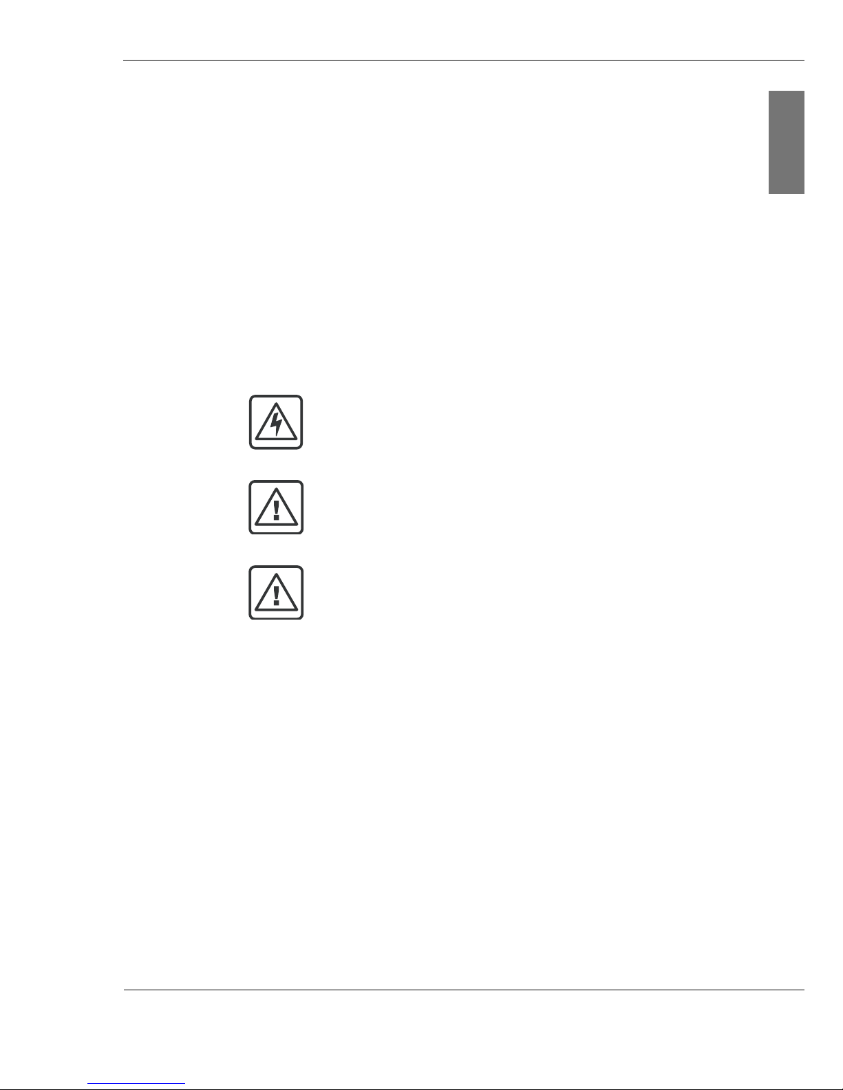
The indicator word on the warning signs denotes one of the
following risk levels:
DANGER!
Denotes a major extraordinary risk from electrical current,
failure to observe which could lead to serious injury or death
WARNING!
Denotes a potentially dangerous situation which may lead to
serious or moderate physical injury and material damage.
CAUTION!
Denotes a potential risk which may lead to slight physical
injury and material damage.
Page 13

12 Instruction m anu all C o n e r g y IP G s t r in g in v e r t e r s e r ie s
2 Sa fe t y
ENGLISH
Page 14
C o n e r g y IP G s t r in g in v e r t e r s e r ie s Instruction m anual 13
3 P r o d u c t d e s c r ip t io n
ENGLISH
3 Pr o d u c t d e s c r ip t io n
3.1 General information on photovoltaic systems
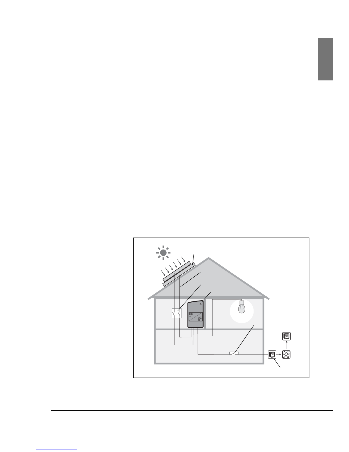
A grid-connected photovoltaic system essentially consists of
the following components:
| Solar power system (1)
The solar power system consists of several photovoltaic
modules connected in sequence or in parallel.
| Safety system
|DC wiring (2)
|DC disconnect (3)
|Inverter (4)
|AC wiring
| AC disconnect (5)
| Meter cabinet with circuit allocation, consumption and
feed-in meter and house connection (6)
Fig. 3-1: House with photovoltaic system
(1)
(2)
(3)
(4)
(5)
(6)
Page 15

14 Inst ruction m an u al C o n e r g y IP G s t r in g in v e r t e r s e r ie s
3 P r o d u c t d e s c r ip t io n
ENGLISH
Solar power system (1) You can connect up to two photovoltaic module strings
(photovoltaic modules connected in series) to each string
inverter of the Conergy IPG series. If you wish to connect
more strings, use the Multi-Contact branch connector plugs
and sockets. Note the specifications on the string inverter
(see chapter 9.1, page 57).
Check whether the desired string configuration complies with
the voltage and current ranges of your inverter.
Safety system In general, a photovoltaic system does not affect the risk of a
lightning strike on the building; apart from the solar power
system with a roof structure which stands out and is a more
likely strike point. In such cases a lightning conductor system
must be installed. Discuss this with a specialist, who will be
pleased to help you with the selection and installation of a
lightning conductor system.
Regardless of whether or not the photovoltaic system has a
lightning conductor system, the solar power system must be
earthed. Among other things, the earthing provides
protection of persons.
DC wiring(2) Connect the solar power system modules with one another
using solar wiring. Solar wiring generally consists of singlepole cables with double insulation. They are UV and weatherresistant. Conergy recommends the use of sheathed cables.
This type of cable can also be used to connect the module to
the string inverter of the Conergy IPG series.
When choosing the cables, check what cable section can be
connected to the connection boxes of your module. The
section varies from 2.5 to 6.0 mm
2
. Connect the solar cables
to the string inverter using Multi-Contact MC4 connector
plugs and sockets.
DC disconnect (3) Before working on the inverter, and also in the case of fire,
the device must always be disconnected from the solar
power system. To disconnect, actuate the DC disconnect (DC
power circuit breaker). The circuit breaker must be capable of
switching the DC rated current of the solar power system
under full load.
Inverter (4) The question of what inverter types you should install
depends both on the system size and the local
circumstances. With the help of the Conergy IPG sizer
system planning program (see www.conergy.com) you can
determine the optimum combination of solar power system
and Conergy inverters.
Page 16
C o n e r g y IP G s t r in g in v e r t e r s e r ie s Instruction m anual 15
3 P r o d u c t d e s c r ip t io n
ENGLISH
AC disconnect (5) It must be possible to disconnect the AC supply from the grid
(on the AC side) by means of a disconnector. This is a
prerequisite for ensuring the absence of current to the unit,
e.g. during maintenance work. The disconnection device
must be secured against being switched back on.
Integration with the grid
(6)
For power feed to the grid, connect the inverter to the lowvoltage mains.
For systems with AC output up to 4.6 kW, a single inverter is
generally used. For the operation of systems with higher
outputs, several string inverters are used and connected in
several phases.
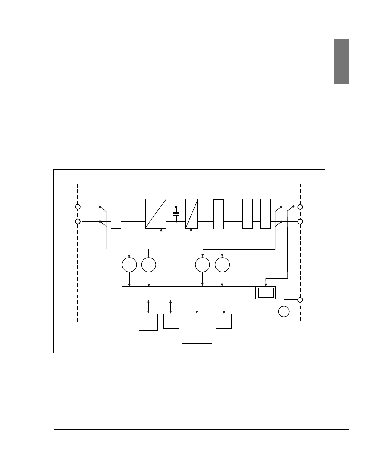
3.2 Block diagram
Fig. 3-2: Schematic block diagram
The electrical energy of the solar power system is conducted
via a sheathed filter. The filter prevents the penetration of
high-frequency line-bound interference. Varistors act as
surge voltage protection. The downstream switching of the
+
-
L1
N
PE
U
DC
I
AC
U
AC
Digital Monit oring
Display
I
DC
Phase
Shifting
EMC filter
LC filter
WR
BMT
Filter surge voltage
protect ion
CAN
In/Out
LED
CTRL
=
=
=
~
Grid protect or
Page 17

16 Inst ruction m an u al C o n e r g y IP G s t r in g in v e r t e r s e r ie s
3 P r o d u c t d e s c r ip t io n
ENGLISH
Conergy Balanced Mode Technology (BMT) of the string
inverter provides for a wide input voltage range. After the
voltage equalisation by the capacitor, the string inverter
converts the direct current from the solar power system into
single-phase alternating current (230 V nominal voltage). The
downstream LC filter has the purpose of equalising the
current for feeding to the grid. Finally, the current flows
through the EMC filter and a grid protector.
The whole process is monitored by a digital control system.
This integrates both MPP tracking and fault current
monitoring.
For safety reasons every photovoltaic system must be
disconnected from the public power grid in various
circumstances such as mains interruption. For this reason,
the string inverters of the Conergy IPG series monitor the
public power grid by means of the phase-shifting process.
Every string inverter has the following data interfaces:
| CTRL
to the Conergy IPG easyconnect (exchange of signals
including DC disconnect, surge voltage protection)
| CAN In
to the Conergy SunReader or
to the previous string inverter
| CAN Out
to the next string inverter
The digital control system controls
| the display (only for inverters of the Conergy IPG string
vision inverter series),
| the LED indicators.
The digital control of the inverter evaluates the following
internal measurements:
| Oon the solar power system side (DC): U and I
| On the grid side (AC): U, I, P and energy
Page 18

C o n e r g y IP G s t r in g in v e r t e r s e r ie s Instruction m anual 17
3 P r o d u c t d e s c r ip t io n
ENGLISH
3.3 Functions
The core of each string inverter of the Conergy IPG series is
formed by the patented Conergy Balanced Mode Technology
(BMT) circuit concept. The circuit consists of a combination
of Insulated Gate Bipolar Transistors (IGBT), diodes and
chokes. The Conergy Balanced Mode Technology ensures a
wide voltage range (U
DC
= 220–800 V) and reduces leakage
current to below the limit values provided for in the building
services.
Wide input voltage
range
Based on the wide input voltage range U
DC
= 220–800 V
there is a wide range of ways to connect to photovoltaic
modules. You can use the space you have available to
optimum effect and at the same time reduce installation
costs.
Module protection On the basis of the Conergy Balanced Mode Technology
(BMT), the photovoltaic modules are also protected from
other electrical components of the photovoltaic system. This
technology effects, among other things, that you can install
the string inverters of the Conergy IPG series as
transformerless inverters in photovoltaic systems with
special photovoltaic modules such as thin-film modules.
Maximum Power Point You increase the yield of your photovoltaic system by
optimum tuning of the string inverter to the photovoltaic
modules. Your system will reach its optimum level of
efficiency when it is working at the Maximum Power Point
(MPP). All string inverters of the Conergy IPG series work
according to the principle of MPP tracking. This ensures that
the system yield is optimised according to the relevant
irradiation conditions. At regular intervals, this process
searches for and inserts the optimum operating point in the
curve of the solar power system.
Display Each string inverter of the Conergy IPG string vision inverter
series has a high resolution display. The display is operated
by touch, and shows all the important information for the
string inverter and the solar power system in a clear
overview. In the case of faults in the string inverter,
diagnostic information and fault warnings are shown on the
display.
Surge voltage
protection
The inputs of the solar power system and the outputs to the
public grid are fitted with Category D surge voltage
protection.
Page 19

18 Inst ruction m an u al C o n e r g y IP G s t r in g in v e r t e r s e r ie s
3 P r o d u c t d e s c r ip t io n
ENGLISH
Monitoring of the public
grid
For safety reasons, each photovoltaic system must be
disconnected from the public power grid in various
circumstances:
| In the case of disconnection or failure of the electricity grid
| In the case of electricity grid faults such as voltage
fluctuations, fault currents or frequency changes
The grid monitoring must be carried out via an independent,
automatic disconnect point or a switch point with disconnect
function, accessible at all times for the utilities. The permitted
type of automatic disconnection depends on the regulations
of the individual countries.
Inverters of the Conergy IPG string inverter series monitor the
grid using the phase-shifting process.
Phase Shifting If there is a fault of the public power grid, each string inverter
of the Conergy IPG series detects this fault on the basis of
the change in frequency of the current.
The frequency of the public grid is at 50 Hz (nominal
frequency). The digital control system of the string inverters
of the Conergy IPG series ensures that the inverter
continuously seeks to increase the input frequency. As long
as the public grid (with nominal frequency 50 Hz) is present,
the inverter cannot increase the input frequency. In the case
of a power outage, the frequency changes, as in this case the
inverter is in a position to increase the input frequency. The
frequency change is monitored by the inverter. It reads a
deviation from 50 Hz as an indication that the public grid is
not available, and automatically disconnects.
Page 20

C o n e r g y IP G s t r in g in v e r t e r s e r ie s Instruction m anual 19
4 C o n e r g y IP G s t r in g v is io n inv e r t e r s e r ie s
ENGLISH
4 C o n e r g y IP G s t r in g v is io n in v e r t e r s e r ie s
Every string inverter of the Conergy IPG string vision inverter
series is equipped with a display. The display is a touch
screen, i.e. you operate the menu by touching the display.
The touch areas Canc el , Di agr am, Set t i ngs and
Di agnost i cs are available for navigation through the display
menu. By touching the appropriate touch areas you will reach
the required menu item. If you change settings you must first
confirm the change. By touching the Cancel area, you will
always be returned to the status and output screen.
In order to be able to operate the display at any time of the
day or night, Conergy recommends the connection of an
external 230 V power supply. If you have chosen combination
with the Conergy IPG easyconnect generator junction box,
you will not need an external power supply, as this is already
integrated in the generator junction box.
The string inverters of the Conergy IPG series work
automatically and require no maintenance. However, should
malfunctions arise, these will be shown immediately on the
display.
When commissioning the inverter, the display automatically
switches on. The first thing to appear is the question in which
language the display text should be shown. The display then
shows the yield of the photovoltaic system. You can call up
updated data for today, the values from the previous day and
photovoltaic system data for the last 7 days via the display.
Page 21
2 0 Inst ruction m an u al C o n e r g y IP G s t r in g in v e r t e r s e r ie s
4 C o n e r g y IP G s t r in g v is io n in v e r t e r s e r ie s
ENGLISH
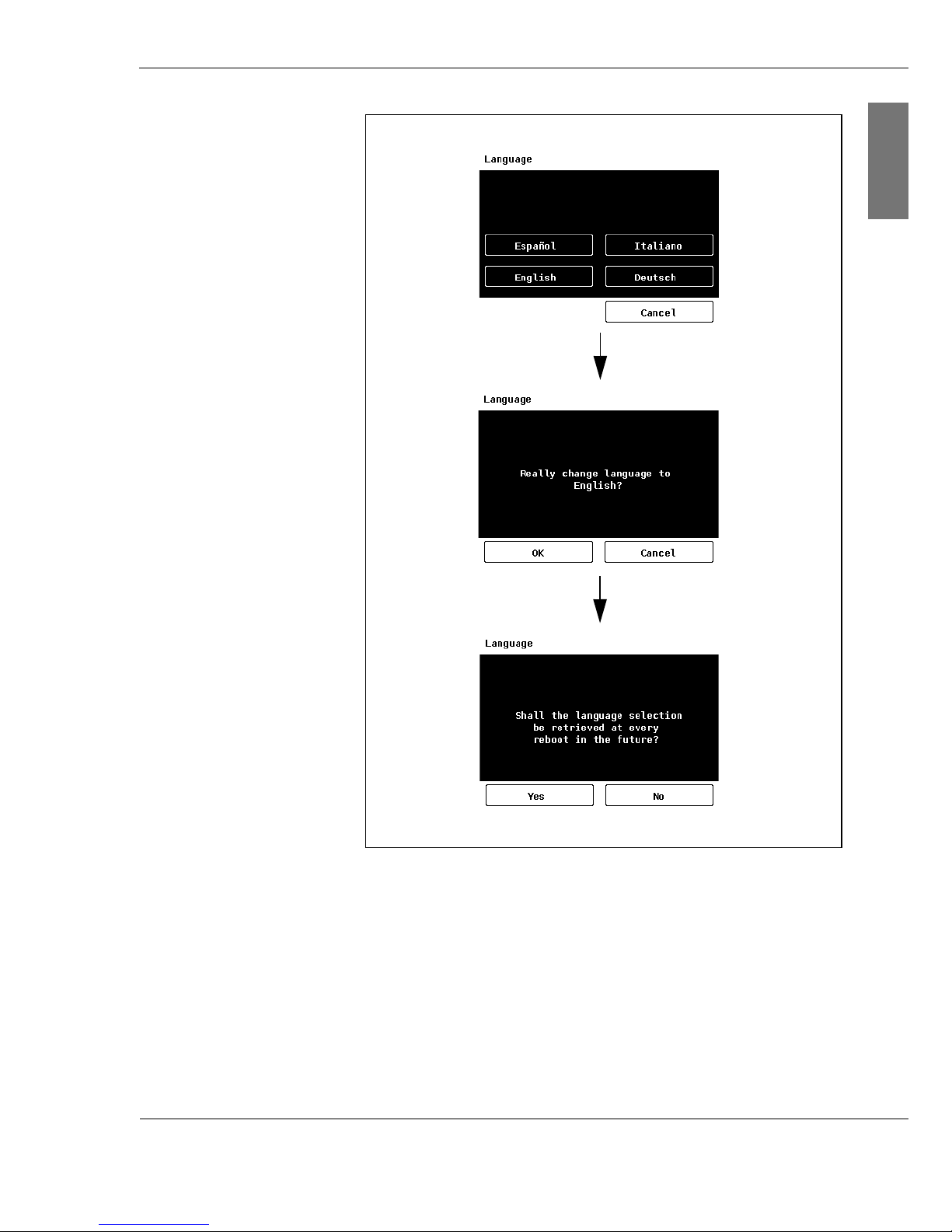
Language You can call up the display text in German, English, Italian or
Spanish.
2. Confirm your selection by touching OK.
Decide whether you want to choose the language every time
an inverter is commissioned.
3. Confirm your selection by touching the button Yes or No.
Selecting the language
1. Select the desired language by touching the relevant
button.
Page 22
C o n e r g y IP G s t r in g in v e r t e r s e r ie s Instruction m anual 2 1
4 C o n e r g y IP G s t r in g v is io n inv e r t e r s e r ie s
ENGLISH
Fig. 4-1: Selecting the language
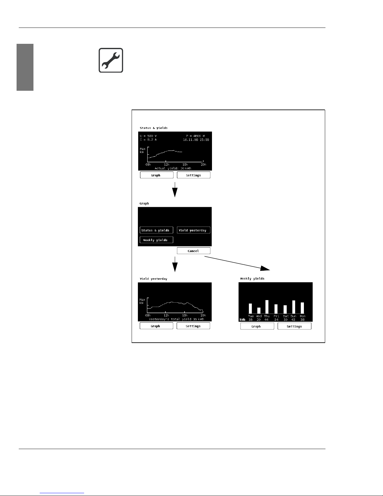
Display You can call up updated data for today, the values from the
previous day and photovoltaic system data for the last 7 days
via the display. The default setting displays current status
and yield. If you want to see the values for the previous day
or the data for the last 7 days, select the Di agr am menu and
then the desired display (Pr ev i ous day; Week).
Page 23
2 2 Inst ruction m an u al C o n e r g y IP G s t r in g in v e r t e r s e r ie s
4 C o n e r g y IP G s t r in g v is io n in v e r t e r s e r ie s
ENGLISH
2. Select the desired display type by touching the
appropriate area.
Fig. 4-2: Selecting the display types
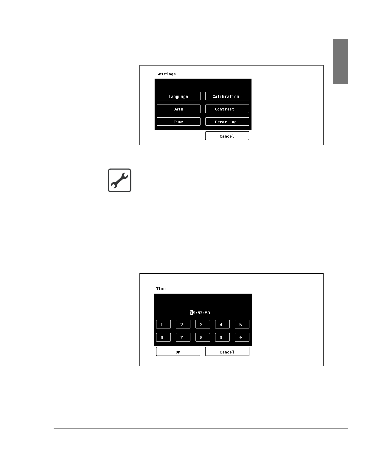
Settings In the Set t i ngs menu you can change the following:
| the language,
| the date,
|the time,
| the calibration,
| the display contrast.
Selecting the display type
1. Select the menu Set t i ngs by touching the appropriate
area.
Page 24
C o n e r g y IP G s t r in g in v e r t e r s e r ie s Instruction m anual 2 3
4 C o n e r g y IP G s t r in g v is io n inv e r t e r s e r ie s
ENGLISH
In the Di agnost i cs submenu you will find fault messages
and diagnostic information for the inverter.
Fig. 4-3:
Set t i ngs
menu
2. Select the setting to be changed by touching the
appropriate area.
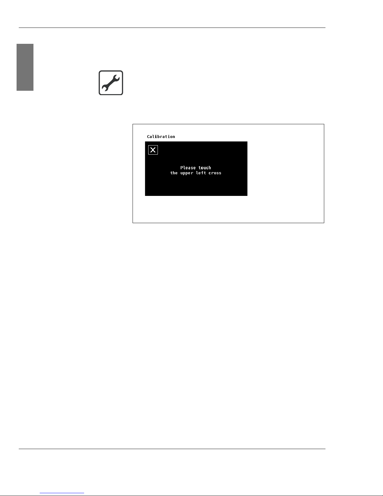
If you want to change the date or the time, the individual
figures will be highlighted in sequence and you can change
them.
3. Change the highlighted figures by touching the appropriate
area on the number pad.
Fig. 4-4:
Ti me
Submenu
4. Confirm your change.
Changing the settings
1. Select the menu Set t i ngs by touching the appropriate
area.
Page 25
2 4 Inst ruction m an u al C o n e r g y IP G s t r in g in v e r t e r s e r ie s
4 C o n e r g y IP G s t r in g v is io n in v e r t e r s e r ie s
ENGLISH
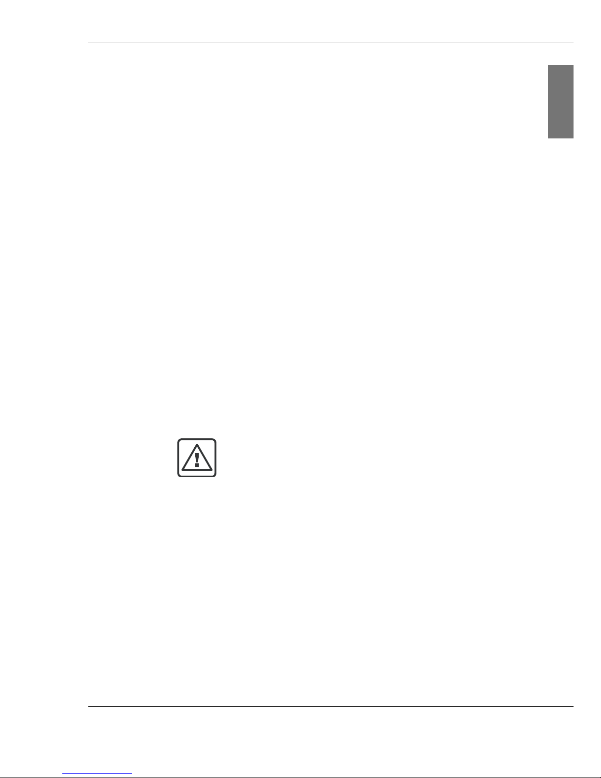
Calibration You can calibrate the display. If you detect that the touch
areas have moved, re-calibrate the display.
2. Touch the exact centre of the crosses shown in sequence.
Fig. 4-5:
Cal i br at i on
Submenu
Calibrating the display
1. Select the Calibration s ubmenu by touching the
appropriate area.
Page 26
C o n e r g y IP G s t r in g in v e r t e r s e r ie s Instruction m anual 2 5
5 Tr a n s p o r t a n d in s t a lla t io n
ENGLISH
5 Tr a n s p o r t a n d in s t a lla t io n
5.1 Included in delivery
| 2 MC4 Plus connector sockets with contact socket
| 2 MC4 Minus connector plugs with contact socket
| Mains plug (5-pin)
| Drill template
|Wall bracket
| Basic installation equipment
| Warranty card
| Instruction manual
Conergy IPG string vision inverter series
| 230 V power supply cable
5.2 Transportation
CAUTION!
Damage due to improper transportation.
When slewing and depositing the load, electronic equipment
can be damaged by the forces of impact. During
transportation, electronic equipment can be damaged by high
temperature fluctuations and air humidity.
| Ensure the device does not suffer impact during
transportation.
| When transporting, do not expose the device to high
temperature fluctuations or air humidity.
Page 27
2 6 Inst ruction m an u al C o n e r g y IP G s t r in g in v e r t e r s e r ie s
5 Tr a n s p o r t a n d in s t a lla t io n
ENGLISH
5.3 Installation
5.3.1 Prerequisites for the installation location
During installation, observe the following:
Weight The Conergy IPG 4000 string inverter weighs 27 kg, the
Conergy IPG 5000 string inverter 28 kg.
The foundation for installation must be firm and capable of
bearing the weight permanently.
Te m pe r at u r e During operation the cooling unit of the inverter can reach a
max. temperature of up to 90 °C.
The foundation for installation must be temperature-resistant.
IP 65 Inverters of the Conergy IPG string inverter series may be
installed both indoors and outdoors due to the IP 65
protection system. If installing outdoors, take care to ensure
that the string inverter is not exposed to wet weather or
direct solar irradiation without protection. For example, it
may be advantageous to install the inverter beneath a
canopy, in order to protect it from unnecessary heat and
wetness. If you have chosen an inverter with display, note
that direct sunlight may make reading more difficult.
Ambient temperature Ideally, the ambient temperature should be between –10 and
40 °C. The inverters of the Conergy IPG string inverter series
achieve the quoted nominal capacity within this temperature
range. In the case of temperatures between 40 and 60 °C, the
output of the inverter may be reduced (derating).
CAUTION!
Damage due to condensate
If the device is brought to the installation location from cold
surroundings, condensation may form, which can lead to
damage to the electronic equipment. The device must be dry
before commissioning.
| Allow two hours after transportation before commissioning
the device.
Page 28
C o n e r g y IP G s t r in g in v e r t e r s e r ie s Instruction m anual 2 7
5 Tr a n s p o r t a n d in s t a lla t io n
ENGLISH
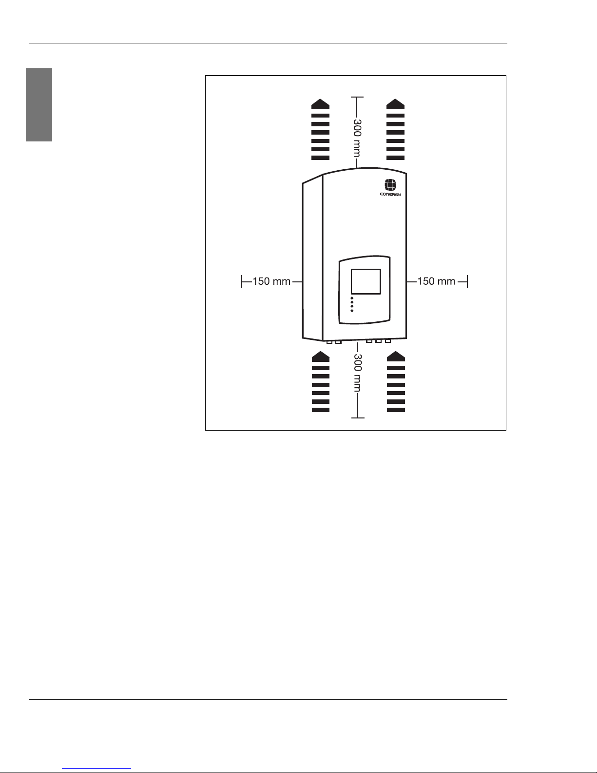
Distances Observe the following distances during installation:
| 300 mm above
| 300 mm below
| 150 mm to the side
| 40 mm from the wall
The 40 mm distance from the wall is ensured by using the
wall bracket supplied.
WARNING!
Risk of fire.
| Do not expose the inverter to highly inflammable gases.
| No highly inflammable liquids should be stored in the
vicinity of the inverter.
| The foundation for installation must be made from a flame-
retardant material.
CAUTION
Air circulation
In order to enable the inverter to be cooled by the ambient air,
it must be installed vertically. No equipment may be installed
above or below the inverter.
|Do not install string inverters one above the other.
Page 29
2 8 Inst ruction m an u al C o n e r g y IP G s t r in g in v e r t e r s e r ie s
5 Tr a n s p o r t a n d in s t a lla t io n
ENGLISH
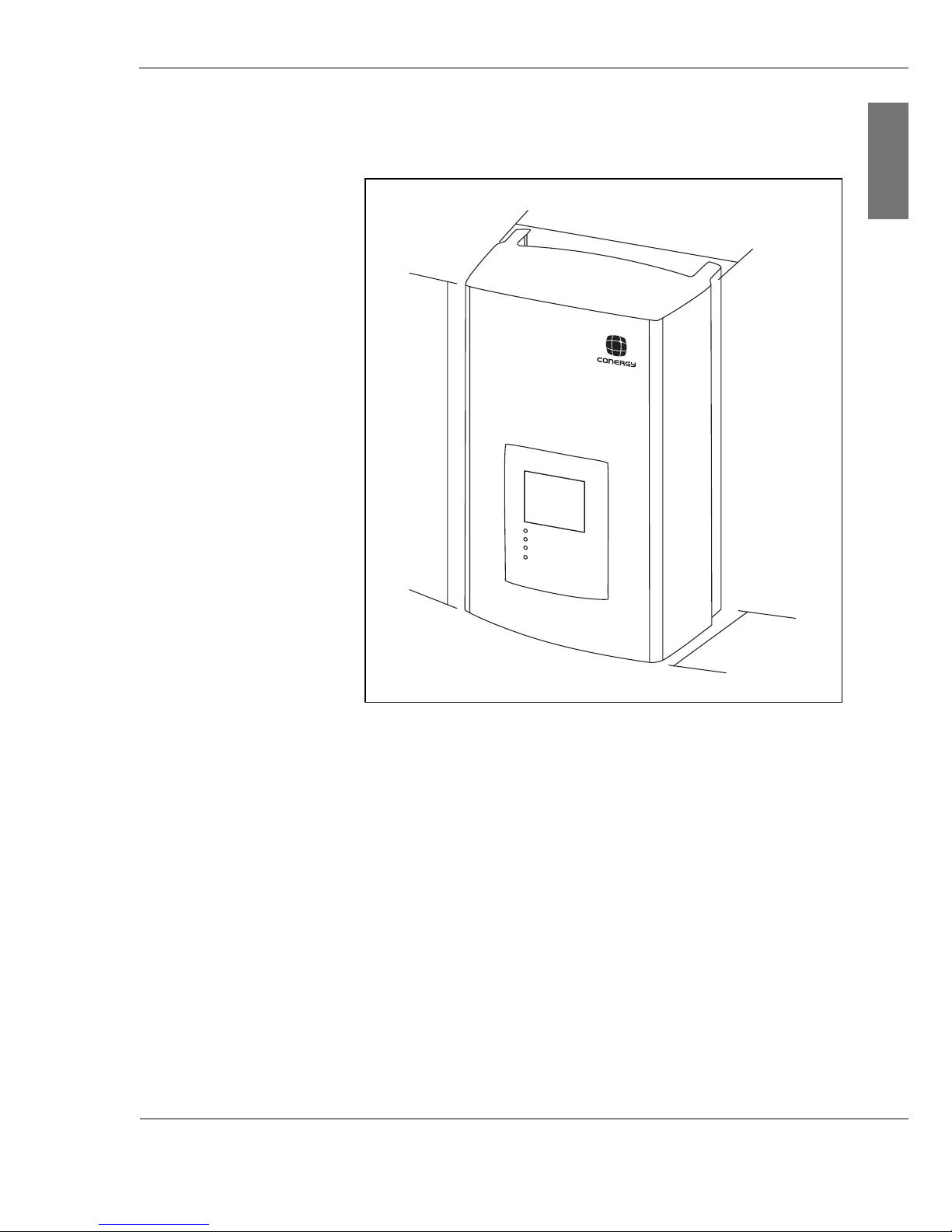
Fig. 5-1: Air circulation around string inverter
If you wish to install a Conergy IPG series string inverter in a
switch cabinet, take care to ensure sufficient air circulation.
Do not cover the front of the unit.
Hot air
Cool air
Page 30
C o n e r g y IP G s t r in g in v e r t e r s e r ie s Instruction m anual 2 9
5 Tr a n s p o r t a n d in s t a lla t io n
ENGLISH
External dimensions The external dimensions of the string inverter are:
W x H x D 377 x 620 x 226 mm
Fig. 5-2: External dimensions of the string inverter
377 mm
620 mm
226 mm
Page 31
3 0 Inst ruction m an u al C o n e r g y IP G s t r in g in v e r t e r s e r ie s
5 Tr a n s p o r t a n d in s t a lla t io n
ENGLISH
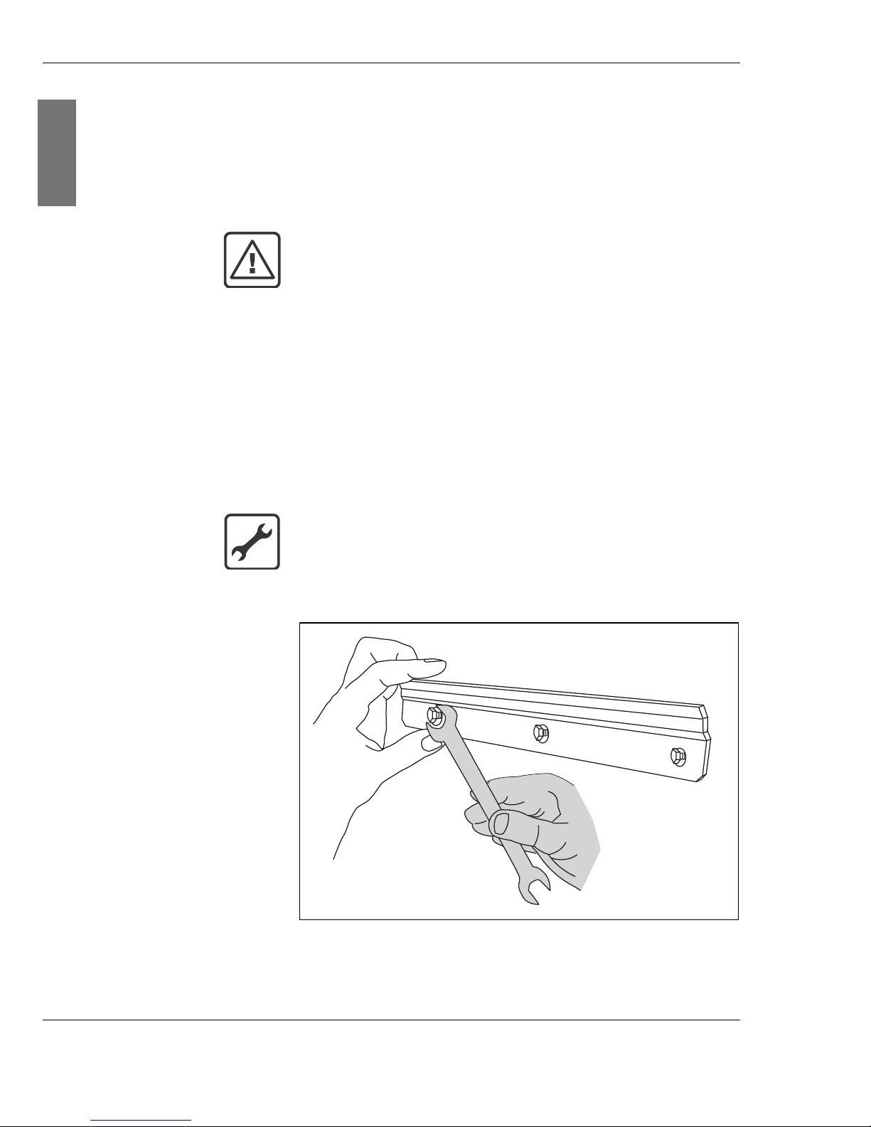
5.3.2 Wall mounting
Conergy IPG string inverter series inverters are intended to
be wall mounted. In order to facilitate installation they are
supplied with a wall bracket, a drilling template and a basic
installation equipment pack with wall plugs and screws.
For wall mounting you will need
| wall bracket,
| drill template,
| wall plugs and screws from the basic installation equipment
pack,
| drill bit (8 mm),
| appropriate open-ended spanner.
Fig. 5-3: Wall bracket installation
CAUTION!
Top-heaviness
| Take the considerable top-heaviness of the device into
consideration during installation.
Wall mounting
1. Drill the holes in accordance with the drilling template
supplied.
2. Screw the wall bracket firmly in place.
Page 32
C o n e r g y IP G s t r in g in v e r t e r s e r ie s Instruction m anual 3 1
5 Tr a n s p o r t a n d in s t a lla t io n
ENGLISH
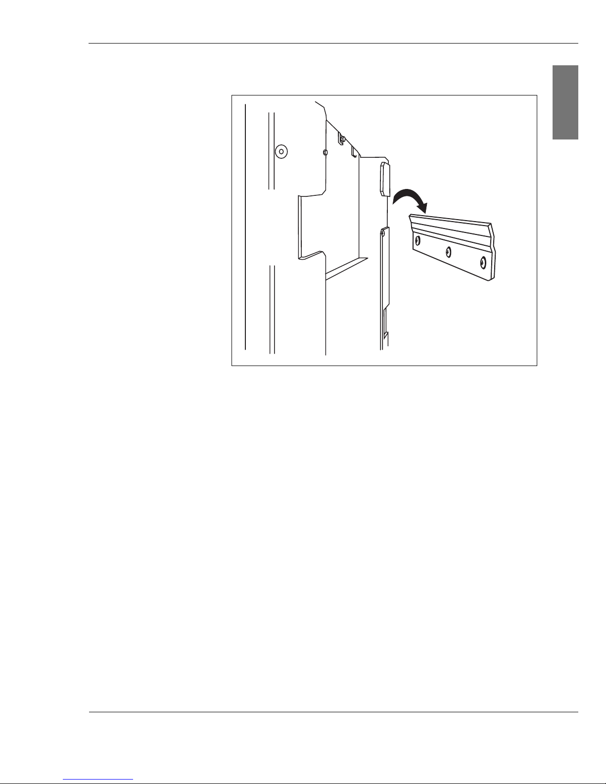
3. Fit the string inverter in place on the wall bracket.
Fig. 5-4: Fitting the string inverter
4. Screw the bottom of the string inverter firmly in place.
The bottom fixings of the string inverter are both to fix the
device in place and also to ensure that it cannot accidentally
be pushed off the wall bracket.
Page 33

3 2 Inst ruction m an u al C o n e r g y IP G s t r in g in v e r t e r s e r ie s
5 Tr a n s p o r t a n d in s t a lla t io n
ENGLISH
Page 34
C o n e r g y IP G s t r in g in v e r t e r s e r ie s Instruction m anual 3 3
6 In s t a lla t io n a n d c o m m is s io n in g
ENGLISH
6 In s t a lla t io n a n d c o m m is s io n in g
6.1 Basic safety instructions
Before starting any work on electrical installations please
observe the following safety rules:
| Disconnecting from the mains
Disconnect the voltage from the device.
| Secure against being switched back on
| Make sure power is disconnected
Make sure power is disconnected from all poles, i.e. check
all phases against zero/earth.
| Earthing and short-circuiting
The background to earthing and short-circuiting is that
disconnected sections of wiring which do not run in
parallel can recharge.
| Cover nearby live parts.
DANGER!
A second person must be present during all work on live
system parts and leads. In the event of an unforeseen
electrical accident, that person must be able to switch off the
power supply and provide aid.
WARNING!
Risks from electrical installations!
When commissioning, there may be risks from electrical
installations despite careful installation and compliance with
the basic safety instructions. These include:
| Direct contact with live system parts
| Electrostatic processes
| Short circuits and overloading
Page 35

3 4 Inst ruction m an u al C o n e r g y IP G s t r in g in v e r t e r s e r ie s
6 In s t a lla t io n a n d c o m m is s io n in g
ENGLISH
6.2 Preparation for installation
Solar system By voltage metering on the solar system, you can determine
possible causes of faults (cabling, solar cells in partial
shadow or defective modules) and rectify these prior to
commissioning of the inverter.
Wiring As a single-phase inverter, the string inverter only supplies
power via phase L1. If you operate several inverters of the
Conergy IPG string inverter series in parallel, the feed phase
of the string inverter must be equally distributed over phases
L1, L2 and L3 of the grid.
Sealing plugs Before connecting the cables, remove the sealing plugs from
the Conergy IPG series string inverter. Leave all connections
which are not needed sealed, as otherwise the string inverter
will no longer conform to the requirements of IP 65
protection. Keep the sealing plugs. When a service is
required, you can seal the connections off again with the
sealing plugs.
CAN connection If you have chosen the Internet-based Conergy SunReader
monitoring system, connect the Conergy data logger to the
string inverter using a CAN cable. If you are using more than
one string inverter, connect these with a further CAN cable. If
you use a CAN connection, you must always install a
terminator (120 Ω) on the last element of the connector. The
terminator is included in delivery of the Conergy SunReader.
To o ls r e q uir e d For the electrical installation of the Conergy IPG string
inverter series inverter, you need the following tools:
| Wire stripper (4–25 mm
2
)
| Multi-Contact crimping tool (for MC4 plug)
| Multi-Contact key set (for MC4 plug)
|PZ1 screwdriver
Page 36
C o n e r g y IP G s t r in g in v e r t e r s e r ie s Instruction m anual 3 5
6 In s t a lla t io n a n d c o m m is s io n in g
ENGLISH
6.3 Connections
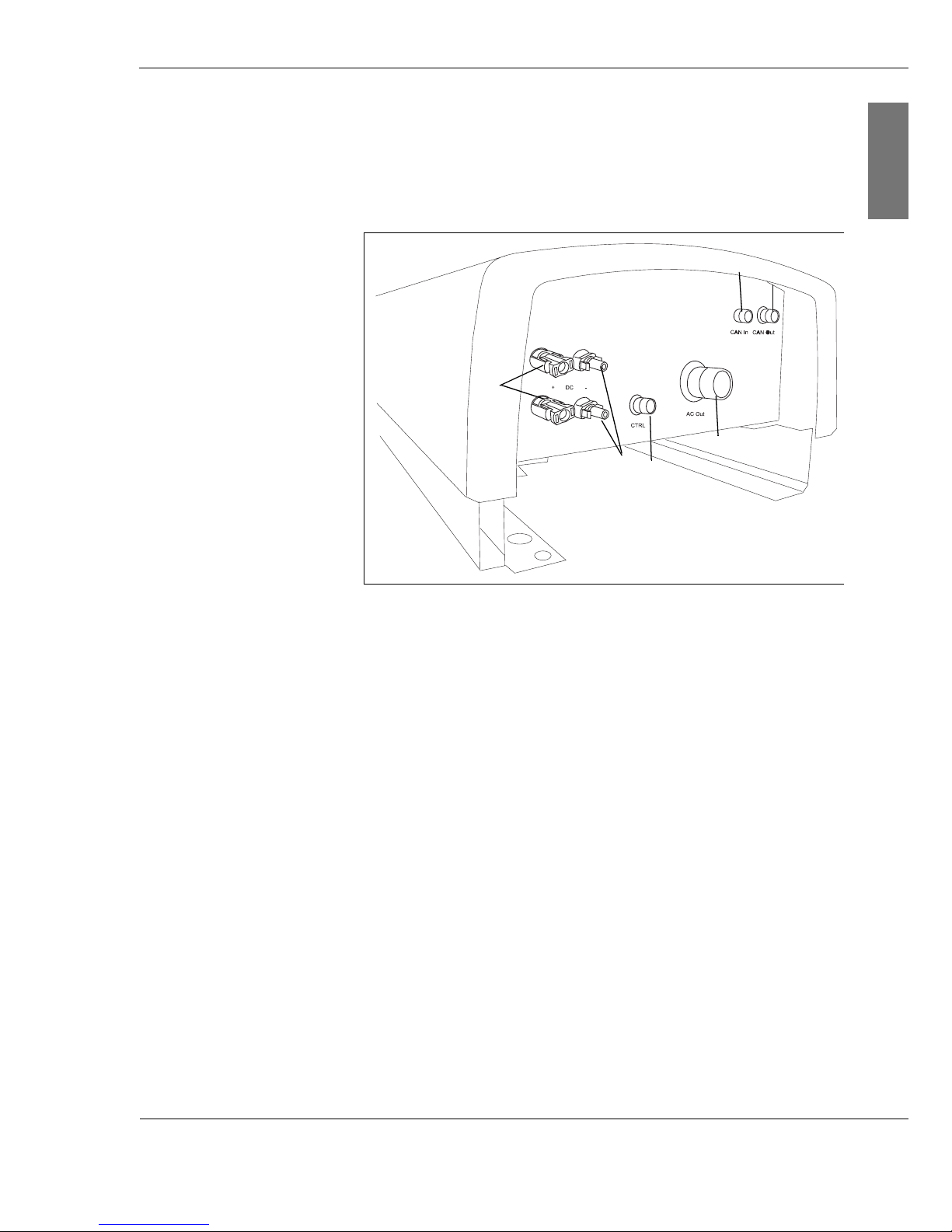
All connections of the Conergy IPG string inverter series
inverters are accessible externally and protected against
accidental contact.
Fig. 6-1: Connections of the string inverter
(1) CAN In
Connection of previous inverter or
to Conergy SunReader
(2) CAN Out
Connection of next inverter
A 120 Ω terminator must be installed at the end of a CAN
connection.
(3) AC Out
Grid connection
(4) CTRL
Connection for Conergy IPG easyconnect
or
external 230 V power supply for the Conergy IPG string
vision inverter series inverter display.
(5) DC–
Solar system connections
(6) DC+
Solar system connections
All connections are provided with sealing plugs on delivery.
(1)
(2)
(3)
(4)
(5)
(6)
Page 37
3 6 Inst ruction m an u al C o n e r g y IP G s t r in g in v e r t e r s e r ie s
6 In s t a lla t io n a n d c o m m is s io n in g
ENGLISH
6.4 Connecting the mains cable
Each inverter of the Conergy IPG string inverter series has a
5-pole AC out socket (see Fig. 6-1, page 35, pos. (3)) for the
connection to the grid. Use a PZ1 screwdriver and tighten the
screws to 0.5–1 Nm. The mains cable must have a cable
section of 4 mm
2
.
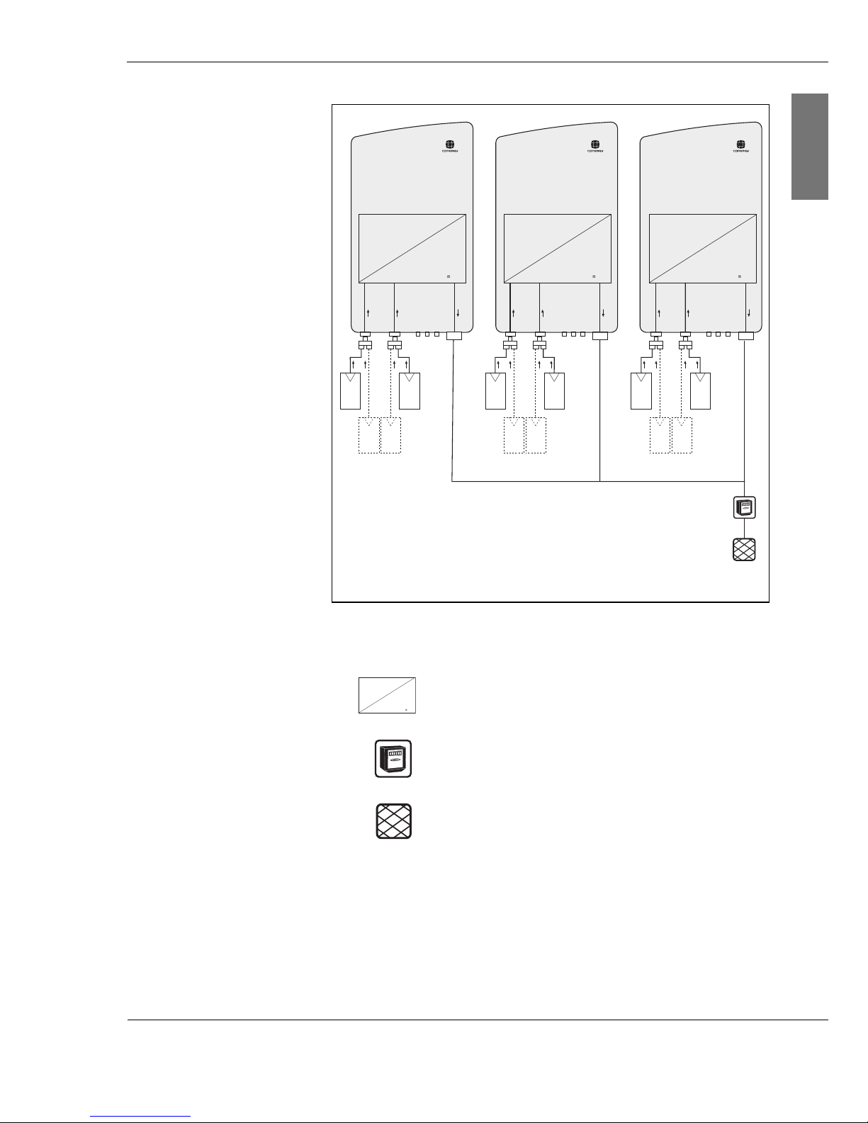
For devices with AC output of up to 4.6 kW a single string
inverter of the Conergy IPG series is used. For the operation
of systems with higher outputs, several string inverters are
used. These are to be connected so that they are distributed
over several phases. The wiring of several string inverters is
shown in the following diagram.
Do not connect any consumers between the Conergy IPG
string inverter series inverter and the utility's meter. The
consumers will otherwise be supplied with electricity which is
not paid for by the utility.
Page 38
C o n e r g y IP G s t r in g in v e r t e r s e r ie s Instruction m anual 3 7
6 In s t a lla t io n a n d c o m m is s io n in g
ENGLISH
Fig. 6-2: Combination of several string inverters
Inverter
3-phase energy meter of the utility
Public power grid
DC
=
AC
DC
=
AC
DC
=
AC
L1 L2 L3
DC
=
AC
Page 39
3 8 Inst ruction m an u al C o n e r g y IP G s t r in g in v e r t e r s e r ie s
6 In s t a lla t io n a n d c o m m is s io n in g
ENGLISH
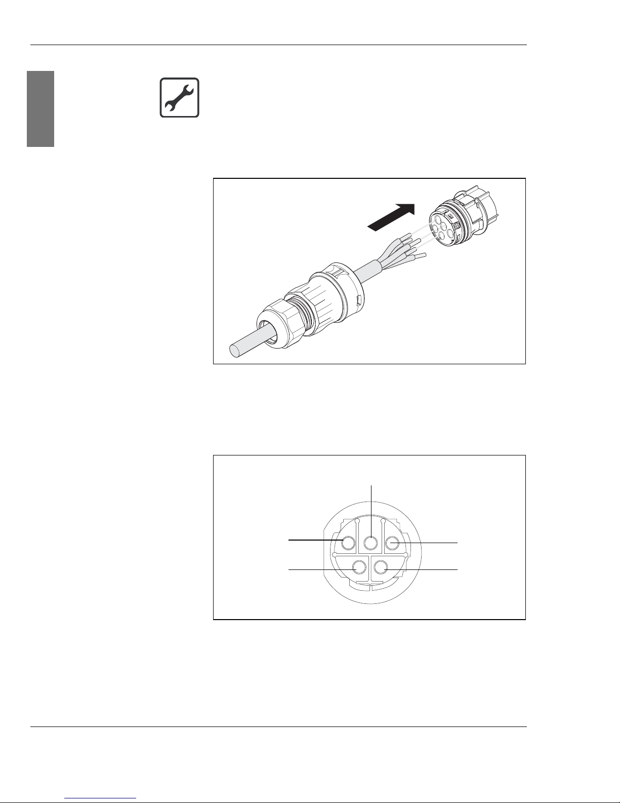
3. Guide the cable through the nut (1) and the cap (2).
Fig. 6-3: Connecting to the end piece
4. Connect the ends of the wire strands to the sockets of the
end piece in accordance with the terminal connecting plan
(3).
Fig. 6-4: End piece terminal connecting plan (3) for stripped
cable
Connecting the mains cable
1. Remove the sheathing from the cable to a length of 35 mm.
2. Strip the cable for a length of 9 mm with a wire stripper.
(3)
(2)
(1)
N
L
2
1
PE (earth)
Neutral
wire
not used
L1 (feed
phase)
not used
Page 40
C o n e r g y IP G s t r in g in v e r t e r s e r ie s Instruction m anual 3 9
6 In s t a lla t io n a n d c o m m is s io n in g
ENGLISH
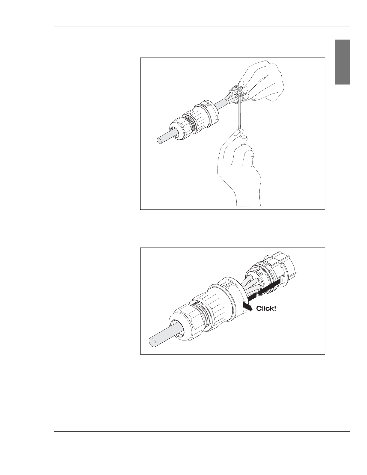
5. Tighten the screws on the end piece (3)
.
Fig. 6-5: Tightening the screws on end piece
6. Connect the end piece (3) to the connector cap (2).
Fig. 6-6: Connecting the end piece to the connector cap
A clicking sound confirms that the components are correctly
connected.
7. Screw the nut (1) tightly in place.
(3)
(3)
(2)
(1)
Page 41
4 0 Inst ruction m an u al C o n e r g y IP G s t r in g in v e r t e r s e r ie s
6 In s t a lla t io n a n d c o m m is s io n in g
ENGLISH
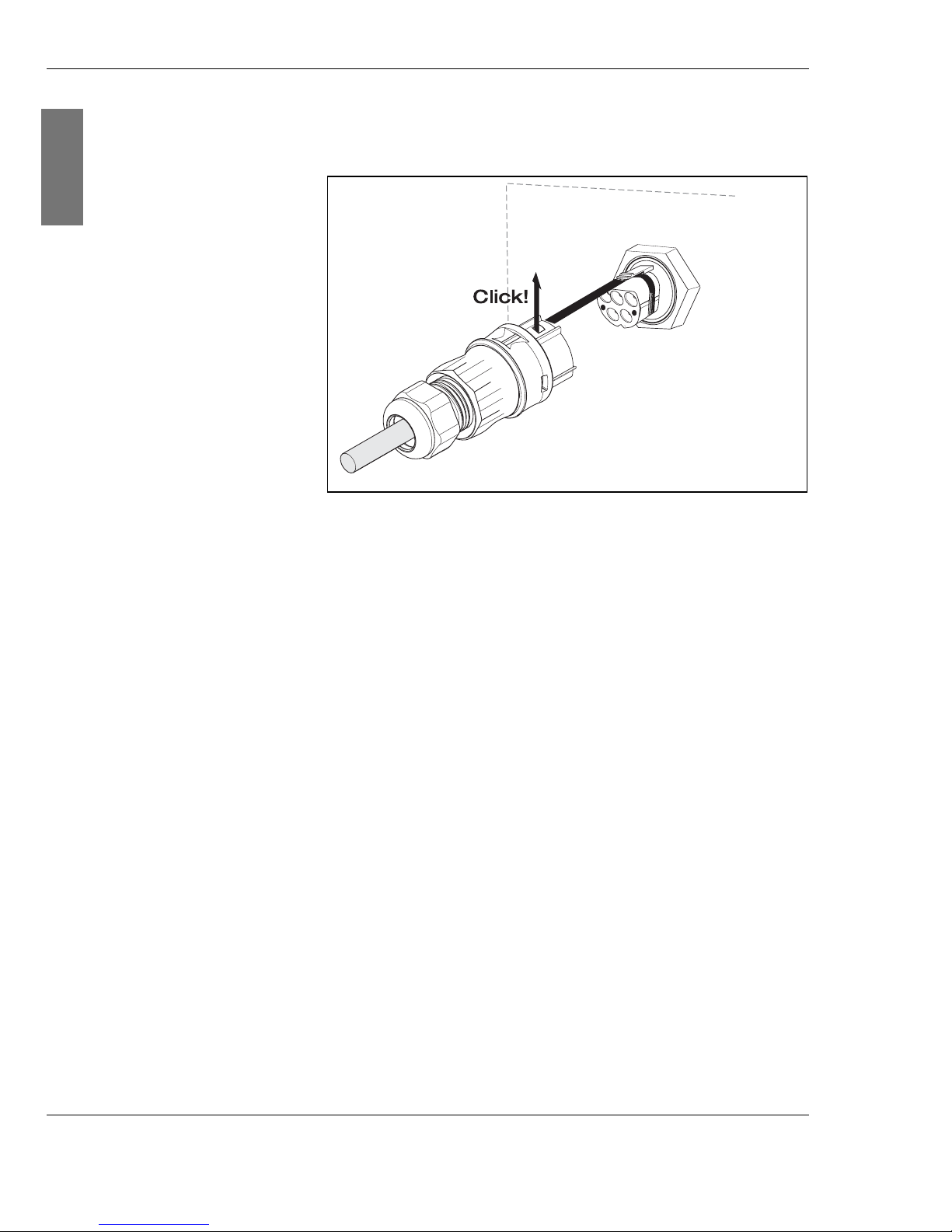
8. Connect the mains plug (1) into the socket (2) of the
Conergy IPG series string inverter.
Fig. 6-7: Connecting the mains plug to the socket
A clicking sound confirms that the components are correctly
connected.
6.5 Connecting the solar system
The solar system connections are made using MC4
connector plugs and sockets. The string inverter is equipped
for 2 photovoltaic strings. If you want to connect more
photovoltaic strings, use Multi-Contact branch connector
plugs and sockets. Note the specifications of the string
inverter.
The MC4 connector plugs and sockets are intended for a
cable section of 4 to 6 mm
2
and an average cable section of
5.5 to 9 mm. To connect the solar system to the inverter you
can use pre-assembled cables or crimp the cables to the
connector plugs and sockets.
If you use pre-assembled cables, you can by-pass the next
stage and connect the cables directly to the string inverter
plugs and sockets (see Fig. 6-12, page 44).
(1)
(2)
Page 42

C o n e r g y IP G s t r in g in v e r t e r s e r ie s Instruction m anual 4 1
6 In s t a lla t io n a n d c o m m is s io n in g
ENGLISH
Tinned cable If copper strands are oxidised, the permitted limit values of
the crimp connection contact resistance may be exceeded.
| Therefore you must only use tinned cables!
To o ls r e q uir e d For the crimping you need:
| Multi-Contact crimping tool (for MC4 plug)
| Multi-Contact key set (for MC4 plug)
3. Connect in sequence the cap of the connector plug or
connector socket (2), the contact socket (3) and the
connector plug (4) or the connector socket (5) to the
stripped wire (1).
Fig. 6-8: Wires with connector plug and socket
DANGER!
Risk of electric shock!
| Disconnect all cables and the plug-and-socket connection
from the power supply.
Connecting the solar power system
1. Remove the sheathing from the solar cables along max.
25 mm.
2. Strip each wire for a length of 7 mm with a wire stripper.
CAUTION!
Material damage due to damaged wires!
| When stripping take care not to cut the wire strands and
not to damage them, as otherwise the strands may later
overheat or break.
(1) (2) (3) (4)
(1) (2) (3) (5)
(+)
(–)
(–)
(+)
Page 43
4 2 Inst ruction m an u al C o n e r g y IP G s t r in g in v e r t e r s e r ie s
6 In s t a lla t io n a n d c o m m is s io n in g
ENGLISH
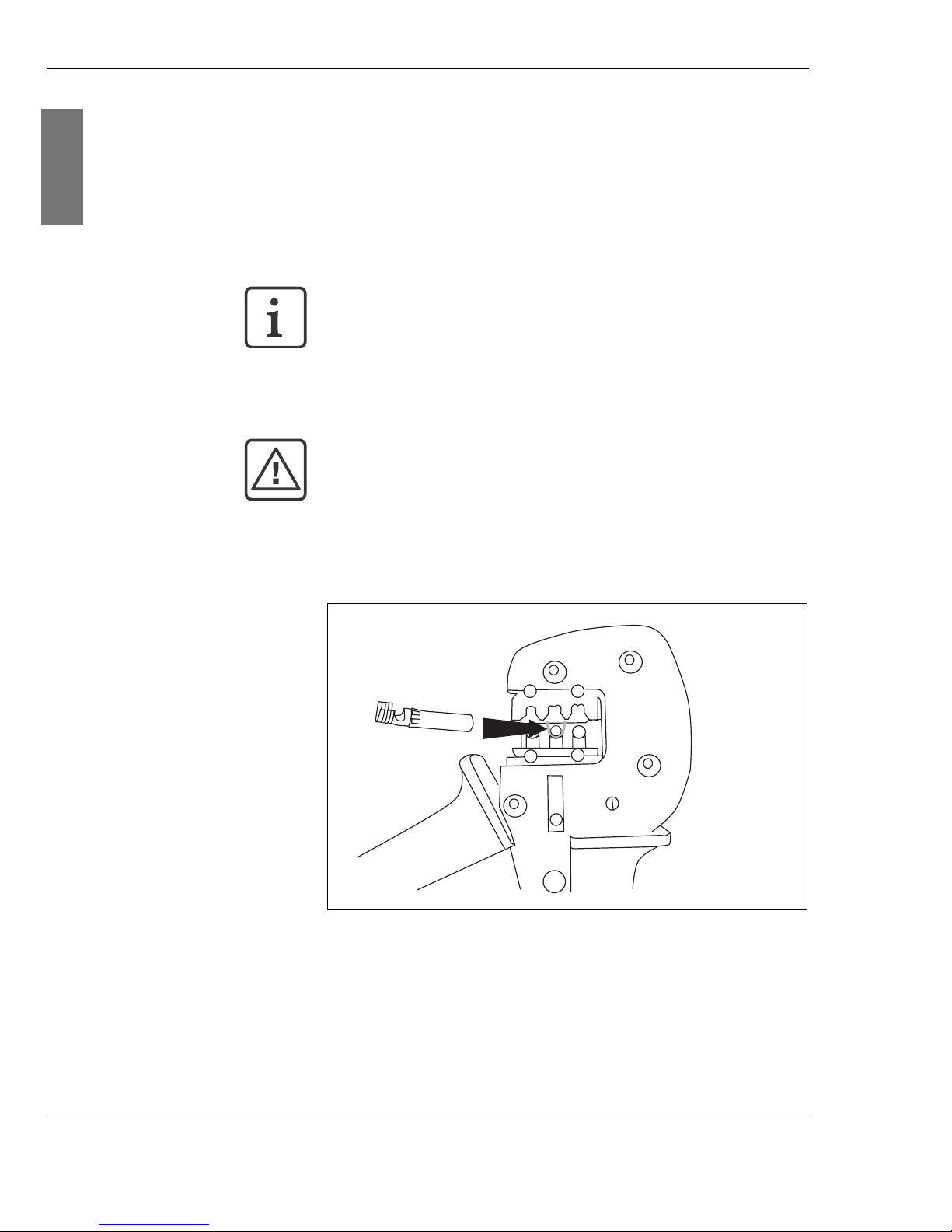
4. Lay the contact socket in the Multi-Contact crimping tool.
5. Guide the end of the stripped wire through the slot of the
crimping tool and into the contact socket.
6. Turn the contact socket so that the crimping lugs are
aligned against the upper crimping jaw.
Fig. 6-9: Introducing the contact socket to the crimping tool
7. Press the crimping tool firmly together and then open it.
The contact socket is crimped to the wire. Check the
socket is firmly in place.
(1) Stripped wire (4) Connector plug
(2) Cap of the connector plug or
socket
(5) Connector socket
(3) Contact socket
The contact socket fits in the Diameter 4 guide of the
crimping tool.
CAUTION!
Risk of short circuit!
| Guide all the wire strands into the contact socket.
Otherwise a short circuit may occur later.
Page 44
C o n e r g y IP G s t r in g in v e r t e r s e r ie s Instruction m anual 4 3
6 In s t a lla t io n a n d c o m m is s io n in g
ENGLISH
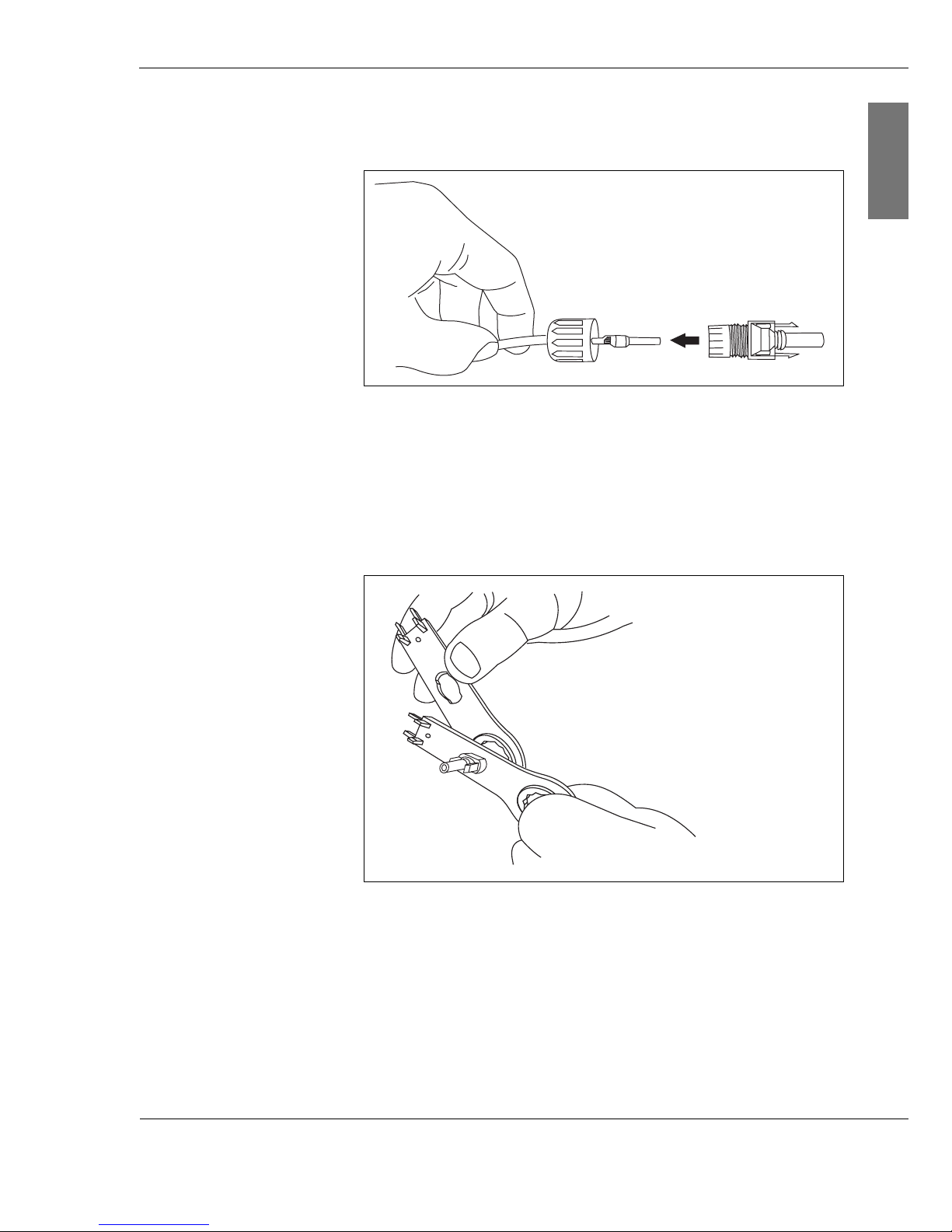
8. Guide the wire through the connector cap and place the
connector socket or connector plug onto the wire.
Fig. 6-10: Connecting the connector socket to the crimped
wire
9. Screw the connector cap and the connector socket or
connector plug together.
10.Tighten the screwed cable gland using the Multi-Contact
installation wrench.
Fig. 6-11: Tightening the screwed element
11.Repeat the crimping procedure for all wires.
Page 45
4 4 Inst ruction m an u al C o n e r g y IP G s t r in g in v e r t e r s e r ie s
6 In s t a lla t io n a n d c o m m is s io n in g
ENGLISH
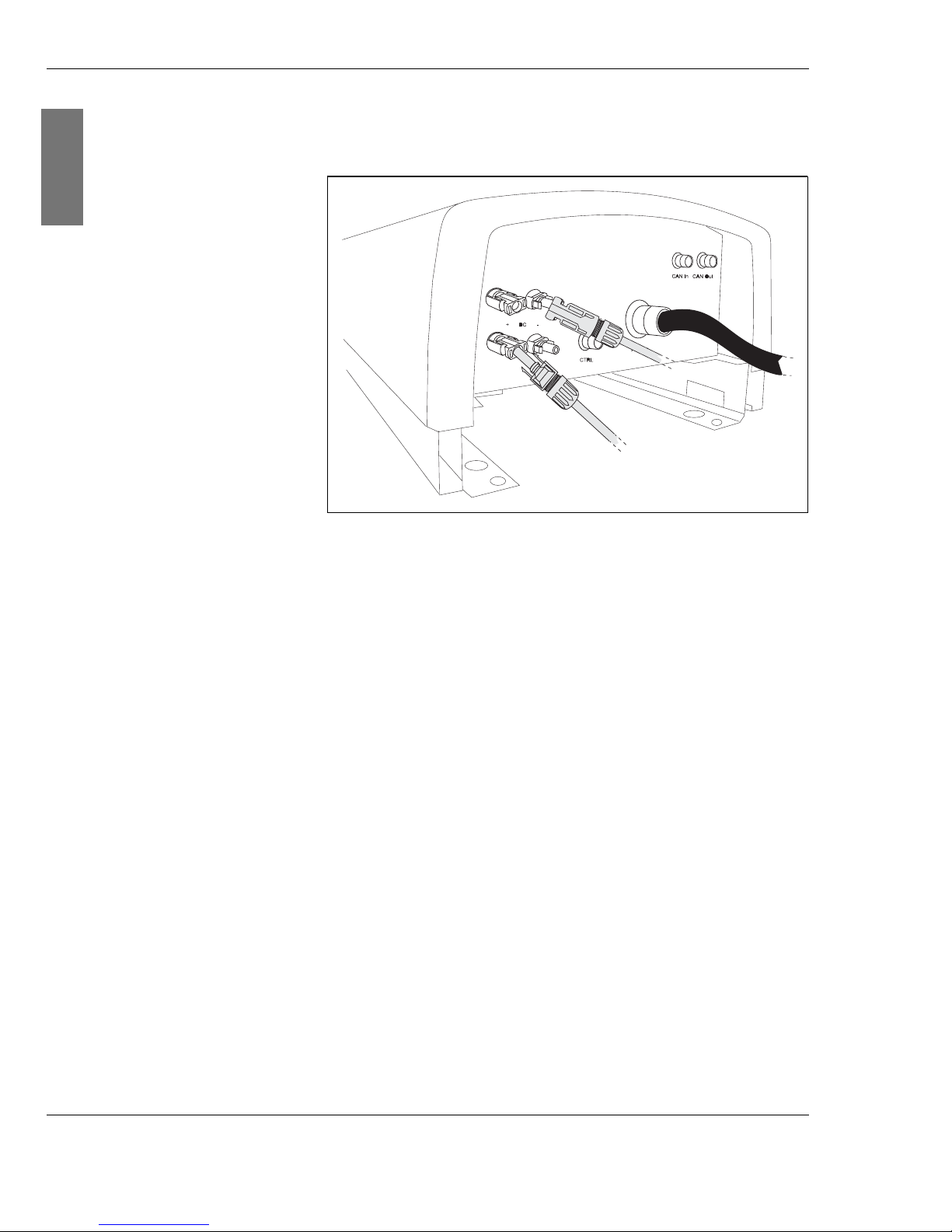
12.Place the connector sockets and connector plugs onto the
plugs and sockets of the string inverter.
Fig. 6-12: Connecting the solar system
Junction box If you have chosen to combine the Conergy IPG series
inverter with the Conergy IPG easyconnect generator
junction box, you will save valuable installation time. The
solar system is connected to the Conergy IPG easyconnect
and from there to the inverter. Connection cables for this
purpose are provided behind the generator junction box. All
you need to do is draw the cables out to the required length
(max. 5 m) and connect them to the connector socket or
connector plug of the inverter. Please see the Conergy IPG
easyconnect generator junction box instruction manual for
further information.
6.6 Connecting the Conergy SunReader:
If you have chosen to use the Internet-based Conergy
SunReader monitoring system, connect the Conergy IPG
series string inverter to the Conergy data logger. Each
Conergy IPG series string inverter has a CAN In connection
(see Fig. 6-1, page 35, pos. (1)). The CAN cable is included
in delivery of the Conergy SunReader. Please see the
Conergy SunReader instruction manual for further
information.
Page 46
C o n e r g y IP G s t r in g in v e r t e r s e r ie s Instruction m anual 4 5
6 In s t a lla t io n a n d c o m m is s io n in g
ENGLISH
You must install a 120 Ω terminator at the end of a CAN
connection (see chapter 6.10, page 46).
If you do not use a Conergy SunReader, leave the sealing
plugs in place on the connector.
6.7 Connecting the 230-V power supply
If you have an inverter with display, you can connect an
external 230-V power supply to the CTRL connection (see
Fig. 6-1, page 35, pos. (4)). You will then be able to operate
the display of your inverter at any time of day or night.
If you have chosen the combination with the Conergy IPG
easyconnect generator junction box, you will not need an
external power supply, as this is already integrated in the
generator junction box.
If you do not want to connect an external 230-V power
supply, please leave the sealing plugs in place on the
connector.
6.8 Connecting Easyconnect
If you have decided to use the Conergy IPG easyconnect
generator junction box, connect the string inverter to this via
the CTRL connection (see Fig. 6-1, page 35, pos. (4)) of the
inverter. The CTRL cable is on the back of the generator
junction box. Please see the generator junction box Conergy
IPG easyconnect instruction manual for further information.
Connecting the Conergy SunReader
1. Connect the CAN cable to the CAN In connection.
2. Tighten the plug by turning manually.
Connecting the 230- V power supply
1. Plug the 230-V power supply cable supplied into the CTRL
connection.
2. Tighten the plug by turning manually.
Connecting Easyconnect
1. Connect the CTRL cable to the CTRL connection.
2. Tighten the plug by turning manually.
Page 47
4 6 Inst ruction m an u al C o n e r g y IP G s t r in g in v e r t e r s e r ie s
6 In s t a lla t io n a n d c o m m is s io n in g
ENGLISH
If you do not use a generator junction box, leave the sealing
plugs in place on the connector.
6.9 Connecting further string inverters
If you have chosen to use the Internet-based Conergy
SunReader monitoring system, connect the Conergy IPG
series string inverters to one another with a CAN cable.
Connect the first inverter to the Conergy SunReader (CAN In)
(see Fig. 6-1, page 35, pos. (1)). Fit a terminator to the last
inverter (see chapter 6.10, page 46). The terminator is
included in delivery of the Conergy SunReader.
If you do not use a Conergy SunReader, leave the sealing
plugs in place on the connectors
6.10 Connecting the terminator
You must install a 120 Ω terminator at the end of a CAN
connection. The terminator is included in delivery of the
Conergy SunReader. The terminator is installed as a bus
connector between pin 4 (CAN-high) and pin 5 (CAN-low) in
an adapter.
Connecting further string inverters
1. Screw one end of the CAN cable to the first string inverter
(CAN In).
2. Screw the other end of the CAN cable to the next string
inverter (CAN Out).
CAUTION!
Short circuit due to inadequate terminator.
An inadequate terminator can cause damage from a short
circuit.
Connecting the terminator
1. Connect the adapter with the integrated terminator to the
CAN Out connection.
2. Tighten the plug by turning manually.
Page 48
C o n e r g y IP G s t r in g in v e r t e r s e r ie s Instruction m anual 4 7
6 In s t a lla t io n a n d c o m m is s io n in g
ENGLISH
6.11 Commissioning
You can commission the string inverter once you have
installed
| the device (see chapter 5.3, page 26) on the wall
| and correctly connected up the solar power system (see
chapter 6.5, page 40) and
| the supply main (AC) (see chapter 6.4, page 36).
2. Switch on the solar system via the DC disconnect.
If the solar power system provides sufficient output, the
Conergy IPG string inverter series inverter will switch on. If
the DC input voltage has reached 250 V
DC
, the string inverter
will supply its internal electronic systems with electric
current. If the solar irradiation is not sufficient to supply
sufficient voltage for the power feed to the grid, the Conergy
IPG series string inverter automatically reduces its output. If
there is a fault during commissioning, you will find further
information in chapter 7, page 49.
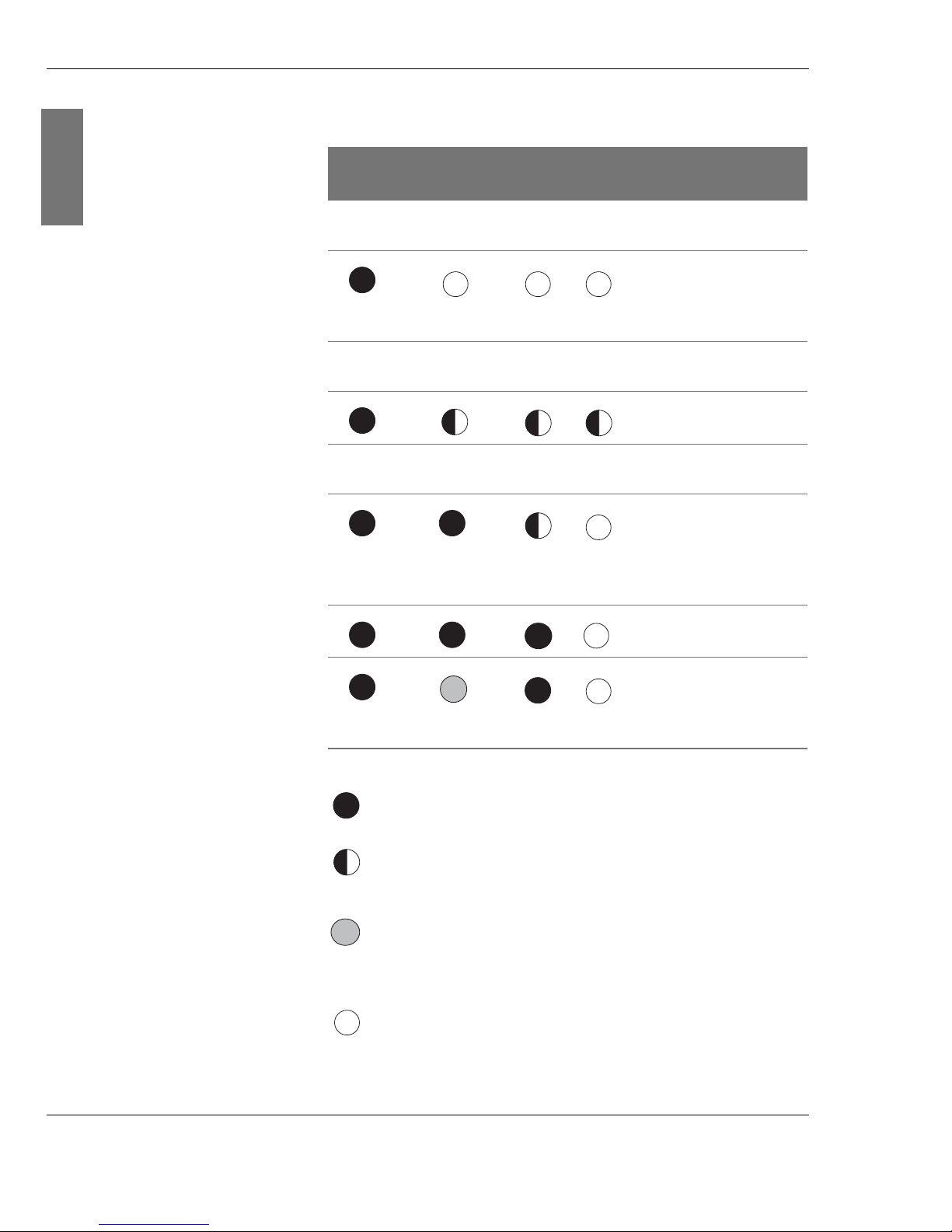
Illumination or flashing of the LED indicators show the status
of the inverter and the current stage of commissioning.
WARNING!
Risks from electrical installations.
When commissioning, despite careful installation and
compliance with the general safety instructions, there may
still be risks from electrical installations. These include:
| Direct contact with live system parts
| Electrostatic processes
| Short circuits and overloading
Commissioning the inverter:
1. Switch on the mains power supply by switching the
external safety disconnector
Page 49
4 8 Inst ruction m an u al C o n e r g y IP G s t r in g in v e r t e r s e r ie s
6 In s t a lla t io n a n d c o m m is s io n in g
ENGLISH
LED indicators during commissioning
Ready Solar
system
Grid Fault Meaning
After switching on, approx. 10 seconds may elapse before
the LED indicators are illuminated.
U
SG
≥ 250 VDC,
internal electronic
systems are
supplied
30-40 seconds may elapse before test of the LED
indicators.
Internal test of the
LEDs
Preparation for the power feed to the grid may last 2–3
minutes.
Preparation of the
power feed to the
grid connection:
Audible clicking of
the relay
Power feed to the
grid
Grid power
available, stand-by
operation of the
inverter
LED is illuminated
LED is flashing
(LED lights up regularly)
The status of this LED indicator has no
significance for the current information
displayed.
LED is off
Page 50

C o n e r g y IP G s t r in g in v e r t e r s e r ie s Instruction m anual 4 9
7 Tr o u b le s h o o t in g
ENGLISH
7 Tr o u b le s h o o t in g
The Conergy IPG string inverter series inverter works
automatically and without maintenance. However, should
malfunctions arise, these will be indicated by the LED
indicators and/or the Conergy SunReader (see
www.sunreader.de).
The inverter may switch off temporarily in the following
cases:
Grid failure The Conergy IPG string inverter series inverter monitors the
single-phase power feed to the grid by means of the phaseshifting process. If the inverter detects a frequency change in
the public power grid, it interrupts the power feed to the grid.
It switches off. The inverter waits 2 minutes before switching
back on after a grid failure.
DC overvoltage If the DC input voltage exceeds the limit value of 800 V
DC
,
the inverter interrupts the power feed to the grid. It switches
off.
Overheating The Conergy IPG string inverter series inverter is designed to
operate at an ambient temperature of up to 60°C. If this
temperature is exceeded, the inverter interrupts the power
feed to the grid and switches off. Once the temperature sinks
back to below the limit value of 60°C, the inverter
automatically switches back on after 4 minutes.
Fault current
monitoring
The fault current monitoring system automatically switches
the inverter off when a fault arises. Once the fault is rectified,
the inverter automatically switches on again after 4 minutes.
Page 51

5 0 Inst ruction m an u al C o n e r g y IP G s t r in g in v e r t e r s e r ie s
7 Tr o u b le s h o o t in g
ENGLISH
Conergy Service Please contact Conergy Service in the event of faults. To
enable Conergy Service to respond quickly and accurately,
please provide the following information:
| Invoice number (delivery note if applicable)
| Serial Number of the inverter
| Brief description of the fault
| What is the LED indicator or the display showing?
| Is the fault reproducible?
| Information about the PV system such as module type,
circuitry, solar generator voltage.
| How long is the mains cable and what is its cross-section?
| What are the irradiation conditions?
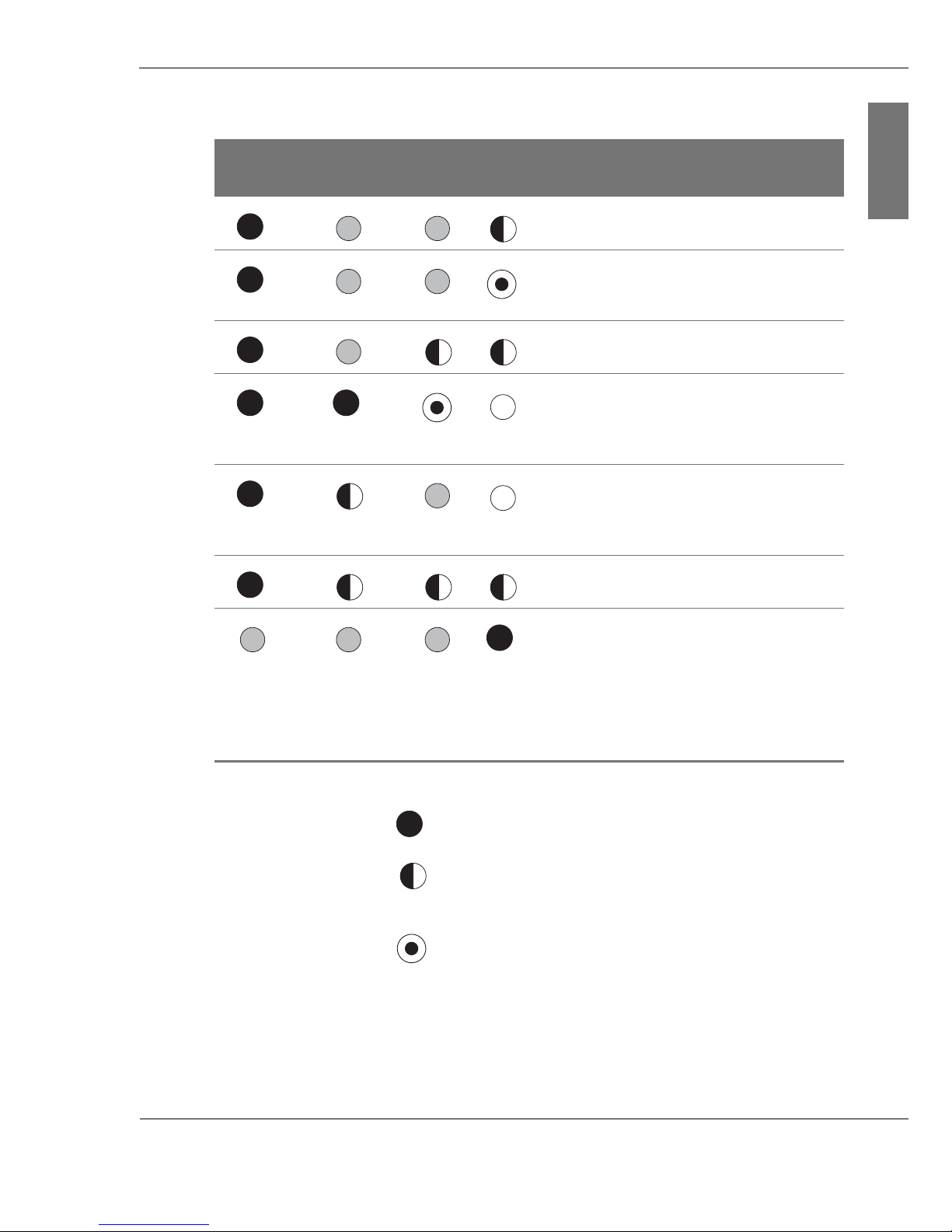
7.1 LED indicator fault messages
The three LED indicators Ready, Solar Generator and Grid
may be illuminated, flashing or flashing blue; the LED
indicator Fault may be illuminated, flashing or flashing red. A
flashing LED indicator indicates that the inverter is in standby mode or there is a fault.
Page 52
C o n e r g y IP G s t r in g in v e r t e r s e r ie s Instruction m anual 5 1
7 Tr o u b le s h o o t in g
ENGLISH
Meaning of the LED indicators
Ready Solar Gen-
erator
Grid
Fault Meaning
Reversible temporary fault (e. g. grid
failure, excess temperature).
Diagnostic information, e. g.
temperature warning, power feed to
the grid during output reduction
Grid fault, inverter is in stand-by
mode
The inverter waits 2 minutes before
switching back on after a grid failure.
Connection: audible clicking of the
relay
Internal electronics systems will not
be supplied due to insufficient solar
generator voltage.
Inverter is not supplying power.
Insulation fault, e.g. earth leakage
Internal fault:
The inverter switches off. If the fault
arises again the next day, it switches
itself off again. The inverter notes
that it is a critical fault and remains
switched off permanently.
Please contact Conergy Service.
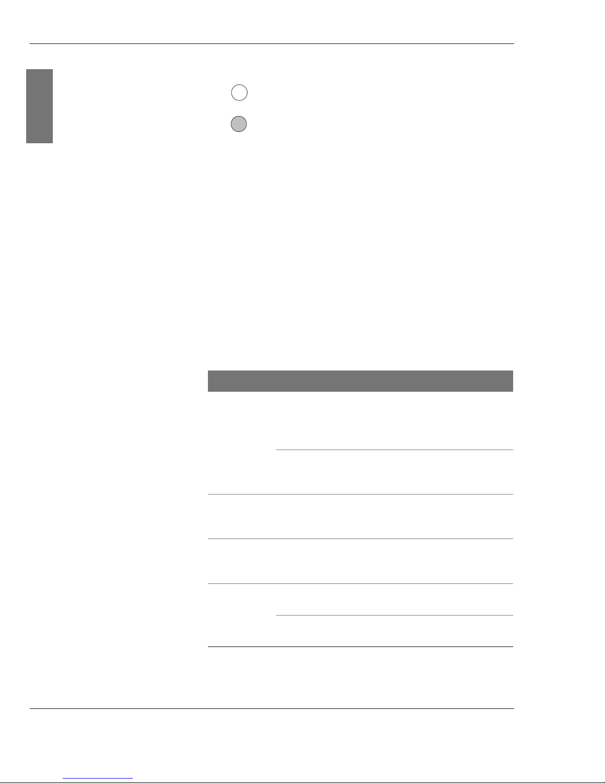
LED is illuminated
LED is flashing
(LED lights up regularly)
LED is flashing
(brief illumination of the LED every 2 seconds)
Page 53
5 2 Inst ruction m an u al C o n e r g y IP G s t r in g in v e r t e r s e r ie s
7 Tr o u b le s h o o t in g
ENGLISH
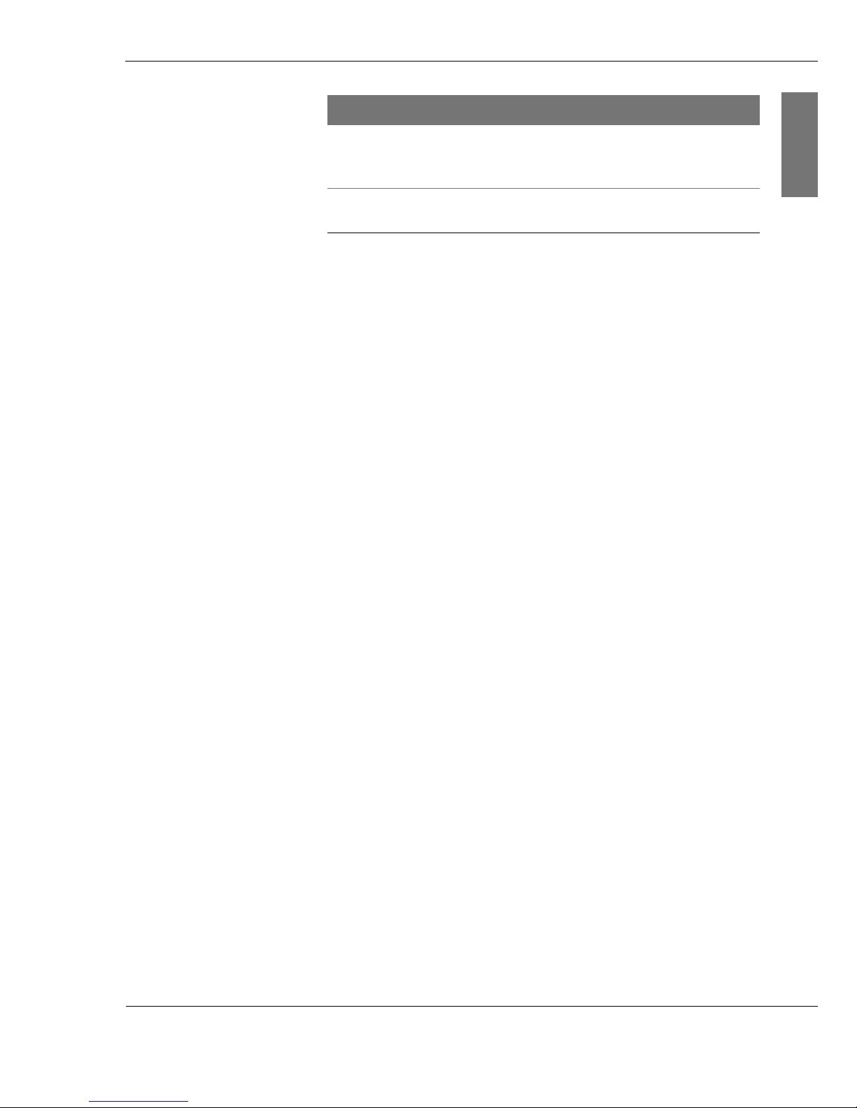
7.2 Fault warnings on the display
If you have chosen a Conergy IPG string vision inverter series
inverter, your inverter will have a high-resolution display.
The inverter differentiates between faults and diagnostic
information. Diagnostic information relates to temporary
faults. If a fault arises, please contact Conergy Service. If a
fault arises, a notice will immediately appear on the St at us
and Yi el d screen. Under Di agnost i cs you will find all
previous faults and diagnostics information.
The following faults may arise and can be rectified as
described. If you have any queries, please contact Conergy
Service.
LED is off
The status of this LED indicator has no
significance for the current information
displayed.
Display Possible cause Remedy
Ov er heat i
ng
Ambient t emperature
is too high, T > 60°C
The inverter needs
cool ambient air.
Check the installation
conditions.
Temperature of the
output stage is too
high
Check the installation
conditions.
DC
ov er vol t a
ge
DC overvoltage Check the idling
voltage of the solar
system.
Ins ul at i o
n f aul t
Earth leakage of the
solar system
Check the solar
system for earth
leakage.
Gr i d f aul t Grid frequency is out
of tolerance
Check the mains
voltage.
AC overvoltage Check the mains
voltage.
Page 54
C o n e r g y IP G s t r in g in v e r t e r s e r ie s Instruction m anual 5 3
7 Tr o u b le s h o o t in g
ENGLISH
Gr i d
i mpedanc e
Grid impedance is
too high
Check the mains
voltage and the grid
connection.
Int er nal
f aul t
e.g. fault with the
electronics
Please contact
Conergy Service.
Display Possible cause Remedy
Page 55

5 4 Inst ruction m an u al C o n e r g y IP G s t r in g in v e r t e r s e r ie s
7 Tr o u b le s h o o t in g
ENGLISH
Page 56
C o n e r g y IP G s t r in g in v e r t e r s e r ie s Instruction m anual 5 5
8 Re m o v a l
ENGLISH
8 Re m o v a l
If you discover a fault to a string inverter of the Conergy IPG
Series, please contact Conergy Service. If they tell you that
Conergy will replace the unit, please remove it. First, switch
off the public power supply and the solar system. Next,
disconnect the various cables from the inverter.
3. Secure the disconnector devices against being switching
back on.
Switching off the inverter
1. Switch off the public power supply by means of an external
disconnect device.
2. Switch off the solar system via an external
DC disconnector.
WARNING!
Unintentional removal of the plug!
If the plug is removed while under load, it may be damaged
and also cause personal injury.
Disconnecting the cables
1. Unscrew the connector pieces of the CAN cable.
2. Remove the connector cables.
Page 57
5 6 Inst ruction m an u al C o n e r g y IP G s t r in g in v e r t e r s e r ie s
8 Re m o v a l
ENGLISH
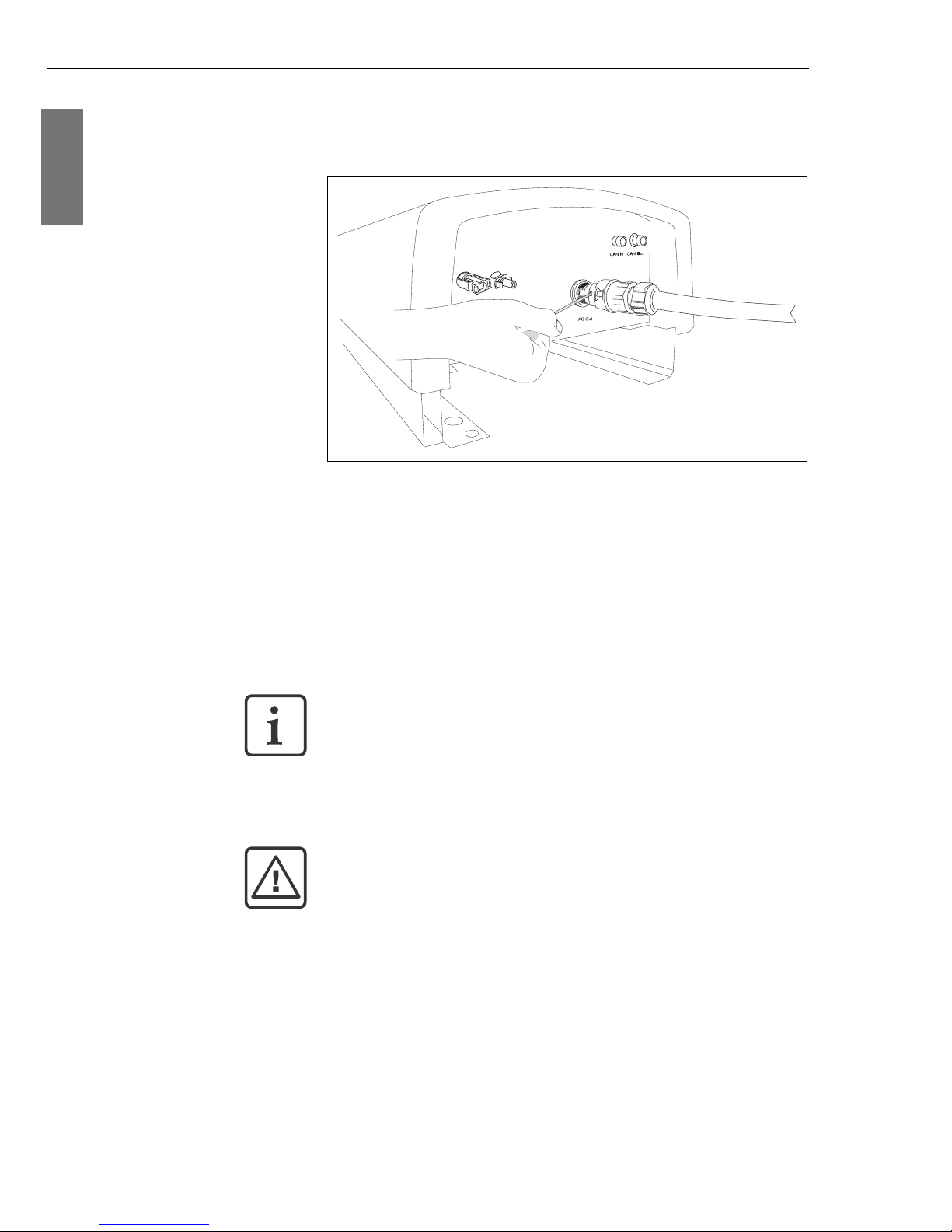
3. Release the mains connector cable by inserting a
screwdriver into the connector socket.
Fig. 8-1: Releasing the mains cable
4. Turn the screwdriver slightly.
5. Pull the connector from the socket.
6. Release the solar cables by pressing the locking clip of the
connector plug manually or by using the Multi-Contact key.
7. Remove the solar cables.
8. Seal all connections with sealing plugs.
9. Release the two fixing screws on the bottom of the string
inverter.
10.Remove the string inverter from the wall.
Take care to ensure that the sealing plugs are correctly in
place. Otherwise, the connections will not be protected
against humidity.
CAUTION!
Risk of burn!
The cooling unit can heat up to 90°C.
| Allow a few minutes before removing the inverter from the
wall.
Page 58
C o n e r g y IP G s t r in g in v e r t e r s e r ie s Instruc tion m anual 5 7
9 A p p e n d ix
GERMAN
9 A p p e n d ix
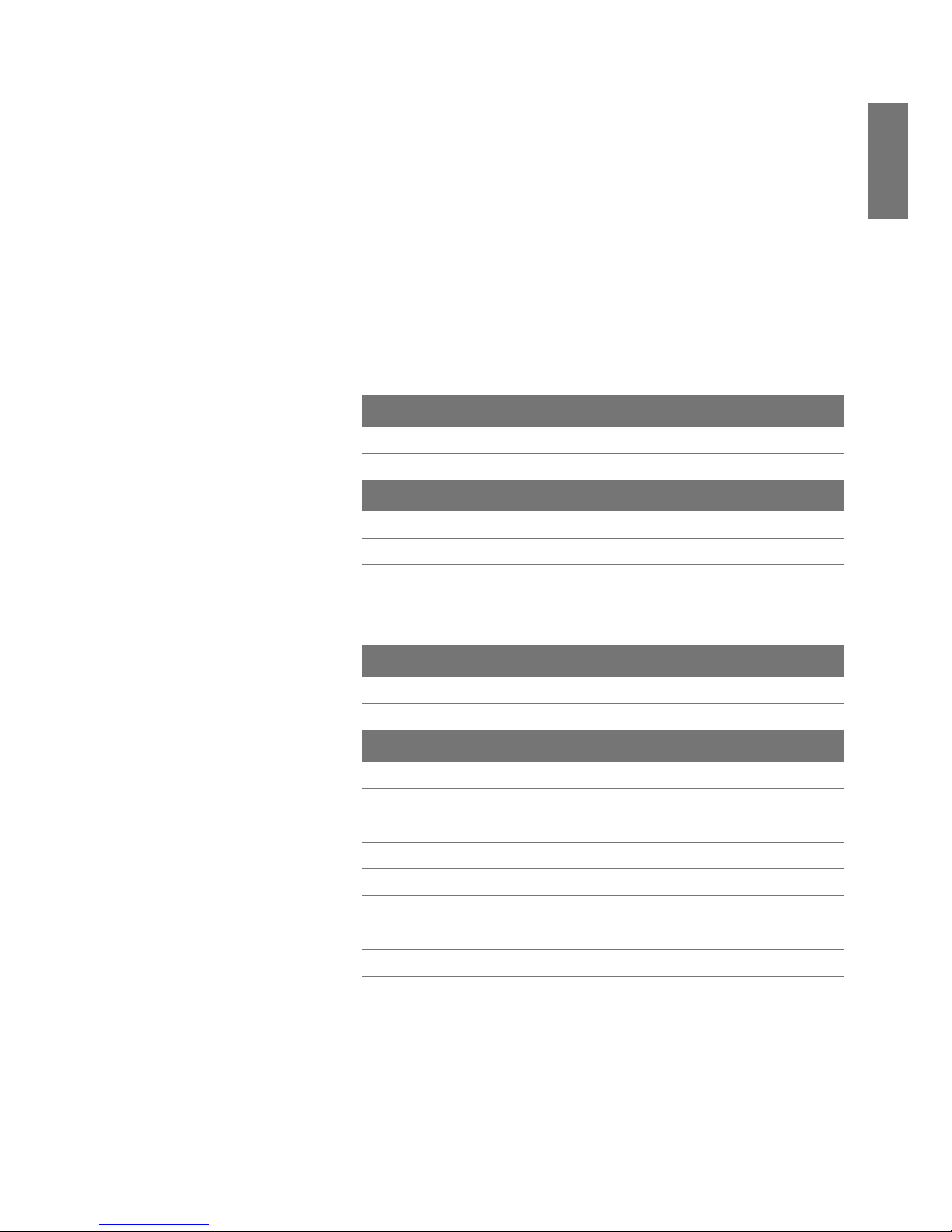
9.1 Specifications
Conergy IPG
4000 and IPG
4000 vision
Conergy IPG
5000 and IPG
5000 vision
Solar system
Nominal solar system power 4,000 W 5,000 W
Max. solar system power 5,000 Wp 6,000 Wp
DC connection data
MPP voltage range 220–750 V 220–750 V
Output in night mode 0 W 0 W
Idling voltage 800 V 800 V
Switch-on voltage 250 V 250 V
Max. input current 15.2 A 16.2 A
Conversion
Max. efficiency level 96.5 96.7
European efficiency level 95.0 96.0
AC network output data
Nominal output 3,400 W 4,600 W
Maximum output 3,800 W 5,000 W
Rated current 14.8 A 20.0 A
Max. current 16.5 A 21.7 A
Frequency 49.8–50.2 Hz 49.8–50.2 Hz
Mains voltage 230 V 230 V
Mains voltage tolerance range ± 15% ± 15%
Distortion factor < 3% < 3%
Reactive factor cos ϕ 11
Page 59
5 8 Instruction m anual C o n e r g y IP G s t r in g in v e r t e r s e r ie s
9 A p p e n d ix
GERMAN
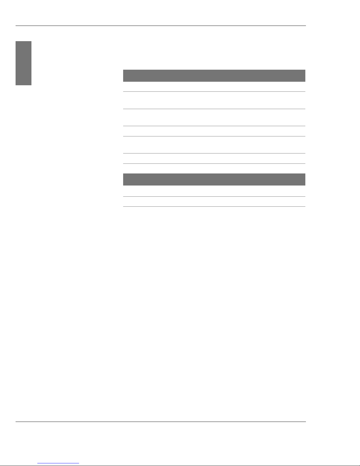
Every transformerless string inverter of the Conergy IPG
string inverter series has:
Please check that the Conergy IPG Series string inverter
complies with the requirements of your utility. Requirements
may vary between utilities, e.g. voltage limit values may vary.
If you become aware of any differences, please contact
Conergy Service.
Conergy IPG
4000 and IPG
4000 vision
Conergy IPG
5000 and IPG
5000 vision
Installation and location data
Weight 27 kg 28 kg
Protection type against environmental factors
IP 65
Ambient temperature –10 to 60 °C
40 to 60 °C with derating
Cooling Convection
Relative atmospheric humidity,
max.
95% (non-condensing)
Mounting type Wall mounted with wall bracket
External dimensions (W x H x D) 377 x 620 x 226 mm
Only Conergy IPG string inverter vision series
Display type
Touch screen
Display size (W x H) 118 x 88 mm
|2 DC inputs
| CAN interfaces
| 1 input phase
(230 V, single-phase)
| Grid connection
| Grid monitoring in accord-
ance with DIN VDE 01261-1
| Sinusoidal current form
| MPP tracking with 99%
accuracy
|Patented Conergy Bal-
anced Mode Technology
circuitry concept
| Reverse battery protec-
tion by short circuit diodes
on the DC side
| Varistors and spark gaps
as AC and DC surge voltage protection (Class D)
Page 60

C o n e r g y IP G s t r in g in v e r t e r s e r ie s Instruc tion m anual 5 9
9 . A p p e n d ix
ENGLISH
9.2 Index
A
Air circulation 27
Amb ient temperature 26
B
Balanced Mode Technology 16, 17
Block diagram 15
C
Conergy IPG easyconnect 4, 40, 45
Conergy IPG sizer 4, 14
Conergy IPG string vision inverter 19, 52
Conergy Service 50
Crimping 36
D
DC 14
Directives 6
Display 17, 19, 52
E
Electrical installation 33
External dimensions 29, 60
F
Fault current monitoring 49
Fault message 49
H
Hotline 50
I
Included in delivery 25
Installation 30
J
Junction b ox 4, 40, 45
L
LED 47, 50
Lightning 14
M
Maximum Power Point 17
Monitoring grid 18
MPP tracking 16
O
Overheating 49
Overvoltage 49
P
Phase Shifting 16, 18
Page 61

6 0 Instruction m anual C o n e r g y IP G s t r in g in v e r t e r s e r ie s
9 . A p p e n d ix
ENGLISH
R
Removal 55
S
Specifications 59
Standards 6
Surge protection 17
System planning program 4
W
Wall mounting 30
Weight 26
Page 62
IPGSTRING-IM-ENG-0611
www.conergy.com
Subject to technical modifications without notice.
2006 © Conergy AG
 Loading...