

Conergy IPG Series, IPG 4000 vision, IPG 5000, IPG 4000, IPG 5000 vision Operating Manual
Conergy IPG string inverter series
Operating manual

C o n e r g y IPG s t r in g in v e r t e r s e r ie s Instruc tion m anual 1
Ta b le o f c o n t e n t s
ENGHLISH
Ta b le o f c o n t e n t s
1Introduction 3
1.1 Short description 3
1.2 Additional products 4
1.3 User group 4
1.4 Signposts 5
1.5 Environmental information 5
1.6 Manufacturer information 6
1.7 Standards and technical directives 6
2 Safety 9
2.1 Intended use 9
2.2 Responsibilities of the owner/operator 9
2.3 Basic safety instructions 10
2.4 Warnings 11
3 Pr o d u c t d e s c r ip t io n 13
3.1 General information on photovoltaic systems 13
3.2 Block diagram 15
3.3 Functions 17
4 C o n e r g y IP G s t r in g v is io n inv e r t e r s e r ie s 19
5 Tr a n s p o r t a n d in s t a lla t io n 2 5
5.1 Included in delivery 25
5.2 Transportation 25
5.3 Installation 26
5.3.1 Prerequisites for the installation location 26
5.3.2 Wall mounting 30

2 C o n e r g y IP G s t r in g in v e r t e r s e r ie s Instruc tion m an u al
Ta b le o f c o n t e n t s
ENGLISH
6 In s t a lla t io n a n d c o m m is s io n ing 3 3
6.1 Basic safety instructions 33
6.2 Preparation for installation 34
6.3 Connections 35
6.4 Connecting the mains cable 36
6.5 Connecting the solar system 40
6.6 Connecting the Conergy SunReader: 44
6.7 Connecting the 230- V power supply 45
6.8 Connecting Easyconnect 45
6.9 Connecting further string inverters 46
6.10 Connecting the terminator 46
6.11 Commissioning 47
7 Tr o u b le s h o o t in g 4 9
7.1 LED indicator fault messages 50
7.2 Fault warnings on the display 52
8 Re m o v a l 5 5
9 A p p e n d ix 5 7
9.1 Specifications 57
9.2 Index 59

C o n e r g y IP G s t r in g in v e r t e r s e r ie s Instruction m anual 3
1 In t r o d u c t io n
ENGLISH
1Introduction
1.1 Short description
The string inverters of the Conergy IPG string inverter series
convert the direct current from the solar power system to
grid-compatible alternating current and supply this to the
public power grid. The string inverters of the Conergy IPG
series are transformerless units for single-phase power feed
to the grid.
This instruction manual relates to the string inverters of the
Conergy IPG series:
| Conergy IPG 4000 vision string inverter,
| Conergy IPG 4000 string inverter,
| Conergy IPG 5000 vision string inverter,
| Conergy IPG 5000 string inverter,
The designation "vision" represents the product version with
a display. The number represents the performance level,
corresponding to the nominal DC input power of 4,000 or
5,000 Wp.
The string inverters belong to the Conergy IPG string inverter
series product group, which in turn is part of the Conergy IPG
series (IPG = Inverter Power on Grid).

4 Instruction m anual C o n e r g y IPG s t r in g in v e r t e r s e r ie s
1 In t r o d u c t io n
ENGLISH
1.2 Additional products
String inverters of the Conergy IPG series can optimally be
used with the Conergy IPG easyconnect generator junction
box. These devices are designed to work together and allow
for simple, time-saving installation. Conergy IPG series string
inverters and the Conergy IPG easyconnect are connected to
one another by means of prepared connections. The Conergy
IPG easyconnect generator junction boxes also offer, for
example, integrated lightning protection and automatic
DC disconnection.
String inverters of the Conergy IPG series can also optimally
be used with the internet-based Conergy SunReader
monitoring system. If you have already opted for the
Conergy IPG easyconnect generator junction box, Conergy
has already integrated the Conergy SunReader into the
individual monitoring system components.
With the help of the Conergy IPG sizer system
dimensioning program you can determine the optimum
combination of the solar power system with the Conergy
inverters.
You can find further information at:
| www.conergy.com
| www.sunreader.de
1.3 User group
This instruction manual is intended for an electrical specialist
appointed by the owner/operator. Basic knowledge of
electrics and electronics is necessary for the monitoring of
the inverter by means of the LED indicators or display.
C o n e r g y IP G s t r in g in v e r t e r s e r ie s Instruction m anual 5
1 In t r o d u c t io n
ENGLISH
1.4 Signposts
The following aids will help orientation when using this
instruction manual:
Headers The headers display the heading of the current chapter.
Footers The footers display the name of the product, the name of the
document, and the page number.
Te x t m a r k u p s The wording of the LED indicators and the connections are
shown in bold. Item numbers are shown in the form (1) and
(2). Display messages are shown in a di f f er ent f ont . The
names of companies other than Conergy are shown in italics.
Symbols
1.5 Environmental information
The Conergy IPG series string inverters are made from
materials, almost all of which can be used again through raw
materials recycling. The device, its accessories, and its
packaging should therefore be recycled in an environmentally
responsible manner.
Denotes the start of an operation with a description of its
objective.
Individually numbered steps follow, which may be
interspersed with background information, illustrations, or
warnings.
Denotes background and additional information for
operational procedures.

6 Instruction m anual C o n e r g y IPG s t r in g in v e r t e r s e r ie s
1 In t r o d u c t io n
ENGLISH
1.6 Manufacturer information
Manufacturer Conergy AG
www.conergy.com
Copyright information All rights to this document are reserved by the product
manufacturer (publisher). The document may not be
reproduced or passed on as a whole or in part without the
express written consent of the publisher. All illustrations,
drawings and other integrated media are subject to
copyright. The manufacturer reserves the right to make
technical modifications to the product.
Conergy AG, 2006
1.7 Standards and technical directives
The string inverters of the Conergy IPG string inverter series
comply with the following standards and directives:
| 89/336/EEC: Council Directive on the approximation of the
laws of Member States relating to electromagnetic
compatibility (amended by 93/97/EEC)
| 73/23/EEC: Council Directive on the approximation of the
laws of Member States relating to electrical equipment for
use within certain voltage limits (amended by 93/68/EEC)
| Electromagnetic Compatibility (EMC) Generic standards –
Immunity for industrial environments (IEC 61000-6-2: 1999,
mod.); German version EN 61000-6-2: 2001
| Electromagnetic Compatibility (EMC) Generic standards –
Emission standard for residential, commercial and light
industrial environments (IEC 61000-6-3: 1996, mod.);
German version EN 61000-6-3:2001 + A11: 2004
| Electromagnetic Compatibility (EMC); Limits for harmonic
current emissions (equipment input current ≤ 16 A per
phase) (IEC 61000-3-2: 2000, mod.); German version EN
61000-3-2: 2000
| Electromagnetic Compatibility (EMC); Limits - Limitation of
voltage changes, voltage fluctuations and flicker in public
low-voltage supply systems, for equipment with rated
current 16 A per phase and not subject to conditional
connection (IEC 61000-3-3: 1994 + A1: 2001 + A2: 2005);
German version EN 61000-3-3:1995 + A1: 2001 + A2: 2005
C o n e r g y IP G s t r in g in v e r t e r s e r ie s Instruction m anual 7
1 In t r o d u c t io n
ENGLISH
| Electronic equipment for use in power installations
(IEC 62103: 2003); German version EN 50178: 1997
| Safety of power converters for use in photovoltaic power
systems – Part 1 – General requirements (IEC 62109-1:
2005)
| Safety of power converters for use in photovoltaic power
systems – Part 2 – Particular requirements for inverters (IEC
62109-2: 2005)
| Information technology equipment - Safety - Part 1:
General requirements (IEC 60950-1:2005-12)
| Automatic disconnection device between a generator and
the public low-voltage grid; DIN VDE 0126-1-1
| Guidelines of the VDEW (German Electricity Association)
governing the parallel operation of in-plant generating
systems with the low-voltage grid of the power supply
company
Please note that the above legal regulations may have been
modified since completion of this instruction manual.
Please also note that countries outside the Federal Republic
of Germany may have their own national directives, laws and
safety regulations.

8 Instruction m anual C o n e r g y IPG s t r in g in v e r t e r s e r ie s
1 In t r o d u c t io n
ENGLISH

C o n e r g y IP G s t r in g in v e r t e r s e r ie s Instruction m anual 9
2 Sa fe t y
ENGLISH
2 Safety
2.1 Intended use
String inverters of the Conergy IPG Series are designed
exclusively for the conversion of direct current from solar
modules to alternating current. Any other use is deemed not
to be as intended.
The inverter may only be installed within acceptable
environmental conditions.
Intended use also includes compliance with the
specifications of this instruction manual.
2.2 Responsibilities of the owner/operator
The owner/operator must ensure the safe operation of the
Conergy IPG string inverter series inverter in accordance with
legal regulations and the safety instructions specified in this
instruction manual and displayed on the device. The
specialist electrician employed by the owner/operator must
observe and follow all the safety instructions specified in this
instruction manual. Prior to assembling, installing,
commissioning and removing an Conergy IPG string inverter
series inverter, the electrician must have read and
understood this instruction manual in full.
Conversion work on Conergy AG equipment and devices may
only be performed by service technicians from Conergy AG.
The instruction manual is a part of the product. If the
contents and in particular the safety instructions and
operating instructions in this instruction manual are not
observed, the product warranty and liability for any damage
shall be invalidated. Conergy shall not be held liable for
damages arising from a failure to observe and follow the
instruction manual or the safety instructions posted on the
device itself, or from any improper use of the device.

10 Instruction m anu all C o n e r g y IP G s t r in g in v e r t e r s e r ie s
2 Sa fe t y
ENGLISH
2.3 Basic safety instructions
| Work on the device may only be carried out by qualified
electricians.
| Photovoltaic systems are electrical systems in which the
connected power source is always active! Depending on
the operating status, voltage from the solar power system
may be supplied to the inverter. This must be noted in
particular when disconnecting from the mains.
| There are high DC voltages present and these may cause
arcing if a malfunction occurs or if plugs or safety devices
are improperly used.
| Cover nearby live parts.
| A second person must be present during all work on live
system parts and leads. In the event of an unforeseen
electrical accident, that person must be able to switch off
the power supply and provide aid.
| Damage due to improper transportation. When slewing and
depositing the load, electronic equipment can be damaged
by the force of impact. During transportation, electronic
equipment can be damaged by temperature fluctuations
and air humidity.
| Do not remove any safety devices and do not disable any
safety devices.
| Observe the warnings posted on the device itself.
| You must immediately renew any warning signs fitted on the
system which have become illegible. Where appropriate,
inform Conergy Service.
| If the inverter is opened, the warranty of the system is
invalidated.
| Keep a copy of this instruction manual directly at the
device.
C o n e r g y IP G s t r in g in v e r t e r s e r ie s Instruction m anual 11
2 Sa fe t y
ENGLISH
2.4 Warnings
Warning signs provide information relating to safety. They
consist of the following:
| Warning symbol (pictograph),
| Indicator word to denote the level of risk,
| Details of the nature and source of the risk
| Information on the possible consequences of disregarding
the risk
Instructions on what to do to avert the risk and prevent
injuries or damage to property
The indicator word on the warning signs denotes one of the
following risk levels:
DANGER!
Denotes a major extraordinary risk from electrical current,
failure to observe which could lead to serious injury or death
WARNING!
Denotes a potentially dangerous situation which may lead to
serious or moderate physical injury and material damage.
CAUTION!
Denotes a potential risk which may lead to slight physical
injury and material damage.

12 Instruction m anu all C o n e r g y IP G s t r in g in v e r t e r s e r ie s
2 Sa fe t y
ENGLISH
C o n e r g y IP G s t r in g in v e r t e r s e r ie s Instruction m anual 13
3 P r o d u c t d e s c r ip t io n
ENGLISH
3 Pr o d u c t d e s c r ip t io n
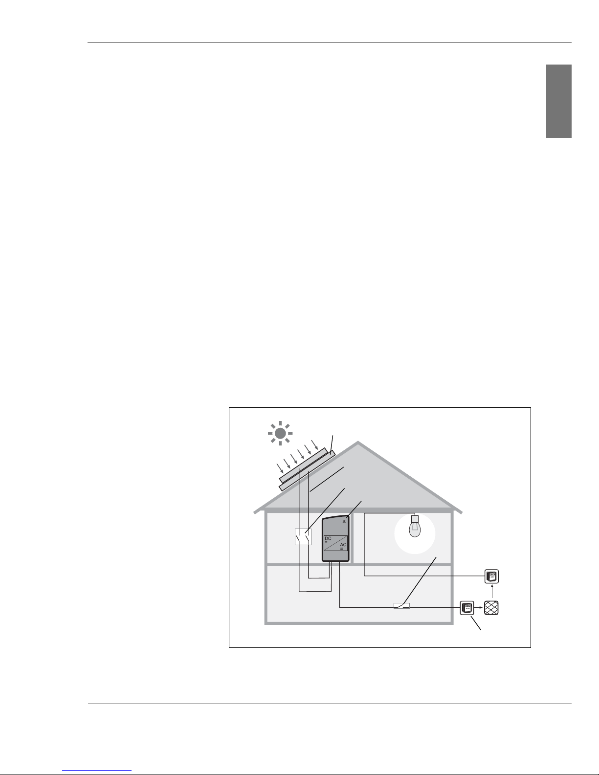
3.1 General information on photovoltaic systems
A grid-connected photovoltaic system essentially consists of
the following components:
| Solar power system (1)
The solar power system consists of several photovoltaic
modules connected in sequence or in parallel.
| Safety system
|DC wiring (2)
|DC disconnect (3)
|Inverter (4)
|AC wiring
| AC disconnect (5)
| Meter cabinet with circuit allocation, consumption and
feed-in meter and house connection (6)
Fig. 3-1: House with photovoltaic system
(1)
(2)
(3)
(4)
(5)
(6)

14 Inst ruction m an u al C o n e r g y IP G s t r in g in v e r t e r s e r ie s
3 P r o d u c t d e s c r ip t io n
ENGLISH
Solar power system (1) You can connect up to two photovoltaic module strings
(photovoltaic modules connected in series) to each string
inverter of the Conergy IPG series. If you wish to connect
more strings, use the Multi-Contact branch connector plugs
and sockets. Note the specifications on the string inverter
(see chapter 9.1, page 57).
Check whether the desired string configuration complies with
the voltage and current ranges of your inverter.
Safety system In general, a photovoltaic system does not affect the risk of a
lightning strike on the building; apart from the solar power
system with a roof structure which stands out and is a more
likely strike point. In such cases a lightning conductor system
must be installed. Discuss this with a specialist, who will be
pleased to help you with the selection and installation of a
lightning conductor system.
Regardless of whether or not the photovoltaic system has a
lightning conductor system, the solar power system must be
earthed. Among other things, the earthing provides
protection of persons.
DC wiring(2) Connect the solar power system modules with one another
using solar wiring. Solar wiring generally consists of singlepole cables with double insulation. They are UV and weatherresistant. Conergy recommends the use of sheathed cables.
This type of cable can also be used to connect the module to
the string inverter of the Conergy IPG series.
When choosing the cables, check what cable section can be
connected to the connection boxes of your module. The
section varies from 2.5 to 6.0 mm
2
. Connect the solar cables
to the string inverter using Multi-Contact MC4 connector
plugs and sockets.
DC disconnect (3) Before working on the inverter, and also in the case of fire,
the device must always be disconnected from the solar
power system. To disconnect, actuate the DC disconnect (DC
power circuit breaker). The circuit breaker must be capable of
switching the DC rated current of the solar power system
under full load.
Inverter (4) The question of what inverter types you should install
depends both on the system size and the local
circumstances. With the help of the Conergy IPG sizer
system planning program (see www.conergy.com) you can
determine the optimum combination of solar power system
and Conergy inverters.
C o n e r g y IP G s t r in g in v e r t e r s e r ie s Instruction m anual 15
3 P r o d u c t d e s c r ip t io n
ENGLISH
AC disconnect (5) It must be possible to disconnect the AC supply from the grid
(on the AC side) by means of a disconnector. This is a
prerequisite for ensuring the absence of current to the unit,
e.g. during maintenance work. The disconnection device
must be secured against being switched back on.
Integration with the grid
(6)
For power feed to the grid, connect the inverter to the lowvoltage mains.
For systems with AC output up to 4.6 kW, a single inverter is
generally used. For the operation of systems with higher
outputs, several string inverters are used and connected in
several phases.
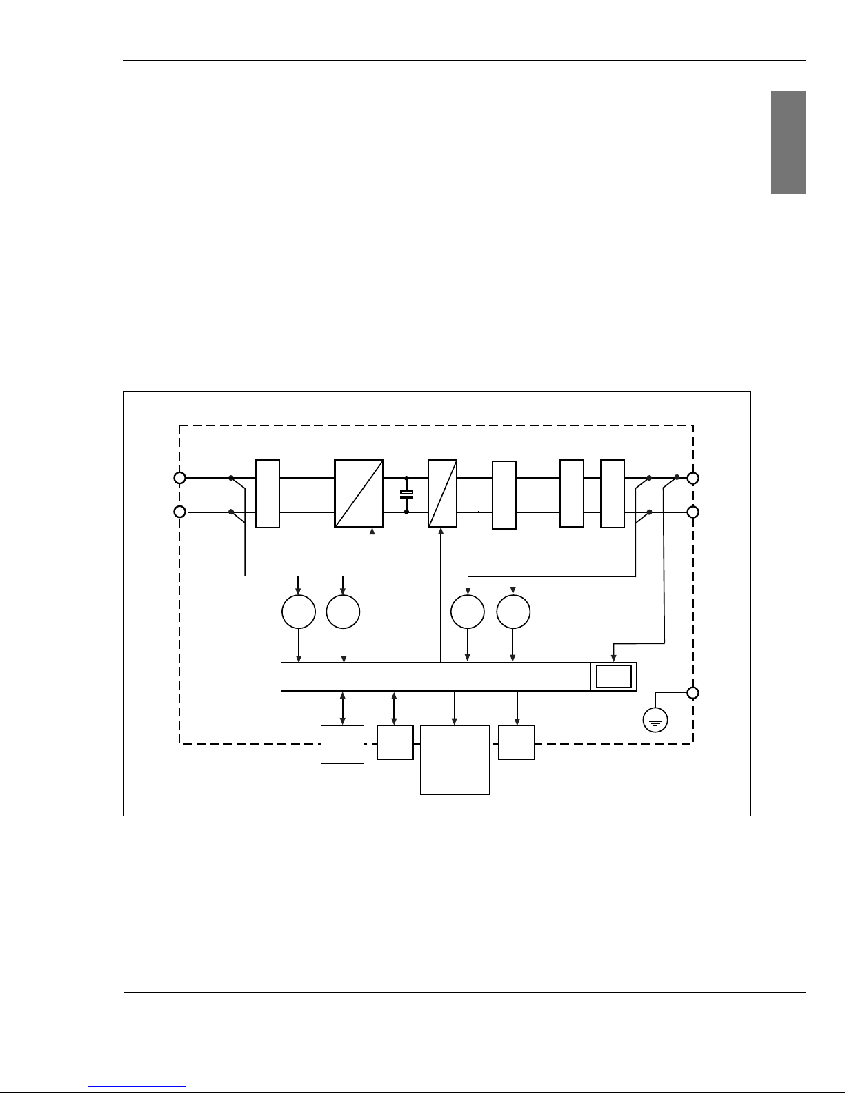
3.2 Block diagram
Fig. 3-2: Schematic block diagram
The electrical energy of the solar power system is conducted
via a sheathed filter. The filter prevents the penetration of
high-frequency line-bound interference. Varistors act as
surge voltage protection. The downstream switching of the
+
-
L1
N
PE
U
DC
I
AC
U
AC
Digital Monit oring
Display
I
DC
Phase
Shifting
EMC filter
LC filter
WR
BMT
Filter surge voltage
protect ion
CAN
In/Out
LED
CTRL
=
=
=
~
Grid protect or

16 Inst ruction m an u al C o n e r g y IP G s t r in g in v e r t e r s e r ie s
3 P r o d u c t d e s c r ip t io n
ENGLISH
Conergy Balanced Mode Technology (BMT) of the string
inverter provides for a wide input voltage range. After the
voltage equalisation by the capacitor, the string inverter
converts the direct current from the solar power system into
single-phase alternating current (230 V nominal voltage). The
downstream LC filter has the purpose of equalising the
current for feeding to the grid. Finally, the current flows
through the EMC filter and a grid protector.
The whole process is monitored by a digital control system.
This integrates both MPP tracking and fault current
monitoring.
For safety reasons every photovoltaic system must be
disconnected from the public power grid in various
circumstances such as mains interruption. For this reason,
the string inverters of the Conergy IPG series monitor the
public power grid by means of the phase-shifting process.
Every string inverter has the following data interfaces:
| CTRL
to the Conergy IPG easyconnect (exchange of signals
including DC disconnect, surge voltage protection)
| CAN In
to the Conergy SunReader or
to the previous string inverter
| CAN Out
to the next string inverter
The digital control system controls
| the display (only for inverters of the Conergy IPG string
vision inverter series),
| the LED indicators.
The digital control of the inverter evaluates the following
internal measurements:
| Oon the solar power system side (DC): U and I
| On the grid side (AC): U, I, P and energy

C o n e r g y IP G s t r in g in v e r t e r s e r ie s Instruction m anual 17
3 P r o d u c t d e s c r ip t io n
ENGLISH
3.3 Functions
The core of each string inverter of the Conergy IPG series is
formed by the patented Conergy Balanced Mode Technology
(BMT) circuit concept. The circuit consists of a combination
of Insulated Gate Bipolar Transistors (IGBT), diodes and
chokes. The Conergy Balanced Mode Technology ensures a
wide voltage range (U
DC
= 220–800 V) and reduces leakage
current to below the limit values provided for in the building
services.
Wide input voltage
range
Based on the wide input voltage range U
DC
= 220–800 V
there is a wide range of ways to connect to photovoltaic
modules. You can use the space you have available to
optimum effect and at the same time reduce installation
costs.
Module protection On the basis of the Conergy Balanced Mode Technology
(BMT), the photovoltaic modules are also protected from
other electrical components of the photovoltaic system. This
technology effects, among other things, that you can install
the string inverters of the Conergy IPG series as
transformerless inverters in photovoltaic systems with
special photovoltaic modules such as thin-film modules.
Maximum Power Point You increase the yield of your photovoltaic system by
optimum tuning of the string inverter to the photovoltaic
modules. Your system will reach its optimum level of
efficiency when it is working at the Maximum Power Point
(MPP). All string inverters of the Conergy IPG series work
according to the principle of MPP tracking. This ensures that
the system yield is optimised according to the relevant
irradiation conditions. At regular intervals, this process
searches for and inserts the optimum operating point in the
curve of the solar power system.
Display Each string inverter of the Conergy IPG string vision inverter
series has a high resolution display. The display is operated
by touch, and shows all the important information for the
string inverter and the solar power system in a clear
overview. In the case of faults in the string inverter,
diagnostic information and fault warnings are shown on the
display.
Surge voltage
protection
The inputs of the solar power system and the outputs to the
public grid are fitted with Category D surge voltage
protection.

18 Inst ruction m an u al C o n e r g y IP G s t r in g in v e r t e r s e r ie s
3 P r o d u c t d e s c r ip t io n
ENGLISH
Monitoring of the public
grid
For safety reasons, each photovoltaic system must be
disconnected from the public power grid in various
circumstances:
| In the case of disconnection or failure of the electricity grid
| In the case of electricity grid faults such as voltage
fluctuations, fault currents or frequency changes
The grid monitoring must be carried out via an independent,
automatic disconnect point or a switch point with disconnect
function, accessible at all times for the utilities. The permitted
type of automatic disconnection depends on the regulations
of the individual countries.
Inverters of the Conergy IPG string inverter series monitor the
grid using the phase-shifting process.
Phase Shifting If there is a fault of the public power grid, each string inverter
of the Conergy IPG series detects this fault on the basis of
the change in frequency of the current.
The frequency of the public grid is at 50 Hz (nominal
frequency). The digital control system of the string inverters
of the Conergy IPG series ensures that the inverter
continuously seeks to increase the input frequency. As long
as the public grid (with nominal frequency 50 Hz) is present,
the inverter cannot increase the input frequency. In the case
of a power outage, the frequency changes, as in this case the
inverter is in a position to increase the input frequency. The
frequency change is monitored by the inverter. It reads a
deviation from 50 Hz as an indication that the public grid is
not available, and automatically disconnects.
 Loading...