

Page 1
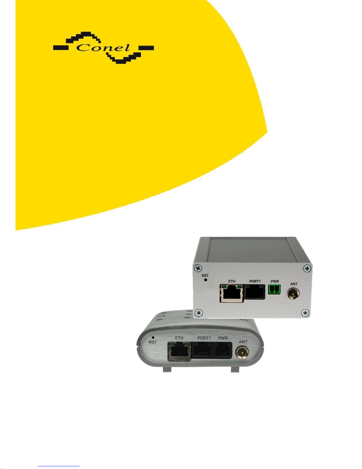
UMTS router
UR5
and
UR5 SL
USER’S GUIDE
Page 2

OBSAH
2
Contents
1. Safety instruction 5
2. Description of the router 6
2.1. Introduction 6
2.2. UMTS technology 6
2.3. HSDPA technology (High Speed Download Packet Access) 7
2.4. Delivery Identification 7
2.5. Antenna Connection 9
2.6. SIM Card Reader 10
2.7. Power Supply 10
2.8. Technical parameters 10
2.9. Description of the individual components of the router 11
2.9.1.
UMTS module 11
2.9.2.
Control microcomputer 11
2.10. User interfaces (Connectors) 12
2.10.1.
Connection of the PWR Supply Connector 14
2.10.2.
Connection of the Port1 Connector – RS232 15
2.10.3.
Connection of the Port1 Connector – RS485 16
2.10.4.
Connection of the Port1 Connector – RS422 17
2.10.5.
Connection of the Port1 Connector – M-BUSD 18
2.10.6.
Connection of the Port1 Connector – CNT 19
2.10.7.
Connection of the ETH Connector 20
2.10.8.
Connection of the Connector USB 20
2.11. Technical specification of optional PORT1 21
2.12. Modem status indication 24
2.13. Putting into operation 24
2.14. Mechanical external dimensions and mounting recommendations 25
3. Expansion port mounting 29
3.1. Expansion port mounting for UR5 29
3.2. Expansion port mounting for UR5 SL 31
4. Changing the SIM cards 33
4.1. Changing the Second SIM card in the UR5 router 33
4.2. Changing the second SIM card in the UR5 SL router 35
5. Configuration setting over web browser 37
5.1. Network Status 37
5.2. DHCP Status 39
5.3. IPsec status 39
5.4. UMTS/GPRS Status 39
5.5. DynDNS status 40
5.6. System Log 40
5.7. LAN Configuration 41
5.8. VRRP Configuration 45
5.9. UMTS/GPRS Configuration 47
5.10. Firewall Configuration 51
5.11. NAT Configuration 53
5.12. OpenVPN Tunnel Configuration 56
5.13. IPSec Tunnel Configuration 59
5.14. GRE Tunnels Configuration 61
5.15. L2TP Configuration 63
Page 3

CONTENTS
3 - 3 - 16.5.2011
5.16. DynDNS Client Configuration 65
5.17. NTP Client Configuration 66
5.18. SNMP Configuration 66
5.19. SMTP Configuration 68
5.20. SMS Configuration 69
5.21. Expansion Port Configuration 76
5.22. USB Port Configuration 77
5.23. Startup Script 79
5.23.1.
IO program 79
5.24. Up/Down Script 81
5.25. Automatic update configuration 81
5.26. Change profile 82
5.27. Change password 82
5.28. Set real time clock 83
5.29. Set SMS service center address 83
5.30. Unlock SIM card 83
5.31. Send SMS 84
5.32. Backup Configuration 84
5.33. Restore Configuration 84
5.34. Update firmware 85
5.35. Reboot 85
5.36. Default settings 86
5.36.1.
LAN Configuration 86
5.36.2.
VRRP Configuration 87
5.36.3.
Firewall Configuration 87
5.36.4.
UMTS/GPRS Configuration 88
5.36.5.
NAT Configuration 89
5.36.6.
OpenVPN Tunnel Configuration 89
5.36.7.
IPsec Tunnel Configuration 91
5.36.8.
GRE Tunnels Configuration 92
5.36.9.
L2TP Tunnel Configuration 92
5.36.10.
DynDNS Configuration 93
5.36.11.
NTP Configuration 93
5.36.12.
SNMP Configuration 93
5.36.13.
SMTP Configuration 94
5.36.14.
SMS Configuration 94
5.36.15.
Expansion Port Configuration 95
5.36.16.
USB Port Configuration 95
5.36.17.
Startup script 96
5.36.18.
Up/Down script 97
5.36.19.
Automatic update 97
6. Configuration setting over Telnet 98
7. Possible problems 99
8. Reference 99
9. FAQ 99
10. Customers support 100
11. Product disposal instructions 101
12. Guarantee Claim Guidelines 102
13. Guarantee certificate 105
Page 4

CONTENTS
4 - 4 - 16.5.2011
Symbols used
Danger – important notice, which may have an influence on the user’s safety or the function
of the device.
Attention – notice on possible problems, which can arise in specific cases.
Information, notice – information, which contains useful advice or special interest.
GPL licence
Source codes under GPL licence are available free of charge by sending an email
to [email protected].
Conel s.r.o., Sokolska 71, 562 04 Usti nad Orlici, Czech Republic
Issue in CZ, 5/16/2011
Declared quality system
ISO 9001:2009
Page 5

SAFETY INSTRUCTION
5
1. Safety instruction
Please, observe the following instructions:
• The communication module must be used in compliance with all applicable international
and national laws and in compliance with any special restrictions regulating the utilization
of the communication module in prescribed applications and environments.
• To prevent possible injury to health and damage to appliances and to ensure that all
the relevant provisions have been complied with, use only the original accessories.
Unauthorised modifications or utilization of accessories that have not been approved may
result in damage to the communication module and in a breach of applicable regulations.
Unauthorized modifications or utilization of accessories that have not been approved may
result in the termination of the validity of the guarantee.
• The communication module must not be opened. Only the replacement of the SIM card is
permitted.
• Caution! The SIM card could be swallowed by small children.
• Voltage at the feed connector of the communication module must not be exceeded.
• Do not expose the communication module to extreme ambient conditions. Protect
the communication module against dust, moisture and high temperature.
• It is recommended that the communication module should not be used at petrol stations.
We remind the users of the duty to observe the restrictions concerning the utilization
of radio devices at petrol stations, in chemical plants, or in the course of blasting works
in which explosives are used.
• Switch off the communication module when travelling by plane. Utilization
of the communication module in a plane may endanger the operation of the plane
or interfere with the mobile telephone network, and may be unlawful. Failure to observe
these instructions may result in the suspension or cancellation of telephone services for
the respective client, or, it may result in legal sanctions; it may also result in both
eventualities.
• When using the communication module in the close proximity of personal medical devices,
such as cardiac pacemakers or hearing aids, you must proceed with heightened caution.
• If it is in the proximity of TV sets, radio receivers and personal computers, the telephone
may cause interference.
• It is recommended that you should create an appropriate copy or backup
of all the important settings that are stored in the memory of the device.
Page 6

EXPANSION PORT MOUNTING
6
2. Description of the router
2.1. Introduction
The UMTS router is a compact electronic device based on the UMTS module which
enables data transfers using HSDPA/UMTS/EDGE/GPRS/GSM technologies.
Primarily, the router expands the capabilities of the UMTS module by the option
of connecting more PC’s by means of the built-in Ethernet interface. In addition, the firmware
of the router provides automatic establishment and maintenance
of HSDPA/UMTS/EDGE/GPRS PPP connection. By means of the integration of a DHCP
server it provides the user with simple installation and Internet access.
In addition, the router is equipped with a USB 1.1 Host interface which is designed only
for connection to a USB device.
By customer request it is possible to equip the router with the PORT1 module and extend
the function of the UMTS router about RS232, RS485/RS422, M-BUSD or CNT (I/O module).
The UMTS router has two versions. The first version is basic UR5 and the second
version is UR5 SL in the aluminum box.
Examples of Possible Applications
• mobile office
• fleet management
• security system
• telematic
• telemetric
• remote monitoring
• vending and dispatcher machines
2.2. UMTS technology
For radio terrestrial part UMTS (Universal Mobile Telecommunication System), which is
marked as UTRA (UMTS Terrestrial Radio Access), is warranted 155 MHz band in frequency
band about the 2 GHz. It is bands 1900–1980 MHz, 2010–2025 MHz and 2110–2170 MHz.
The UMTS system is based on code division of carried channels – use the access
method WCDMA (Wideband Code Division Multiple Access). WCDMA exploits direct spread
spectrum DS (Direct Spread). For transmission the UMTS network exploits two duplex
techniques – transmission modes FDD (Frequency Division Duplex), which is based
on separate frequency channels (i.e. uplink and downlink uses different channels) and TDD
(Time Division Duplex), which is based on separate time (i.e. uplink and downlink uses one
channel, in which both directions are changes in time).
UMTS network consists of three basic entities:
• Basic network CN (Core Network) – own core of network UMTS,
• network UTRAN (UMTS Terrestrial Radio Access Network) – the radio access
network,
Page 7
EXPANSION PORT MOUNTING
7
• users part UE (User Equipment) – entity, which allows the user to access
the UMTS network.
2.3. HSDPA technology (High Speed Download Packet Access)
HSDPA is an improved and extended version of the UMTS-TDD. HSDPA is available
for both UMTS FDD and for UMTS TDD. HSDPA raises significantly bit rate for downlink. It is
attained on the programmer level. It doubles capacity on BTS (Base Transceiver Station),
which allows process of data and signals from more users at one time. HSDPA is based
on a few innovations of network architecture; thanks to this, it has lower latency, faster
reaction on channel change quality and processing of H-ARQ (Hybrid automatic repeat
request) on transmission repeat. Transport channel for HSDPA effectively uses available
frequencies, on which transmits data packets together. Afterwards these packets are divided
between individual users according to specific algorithms.
2.4. Delivery Identification
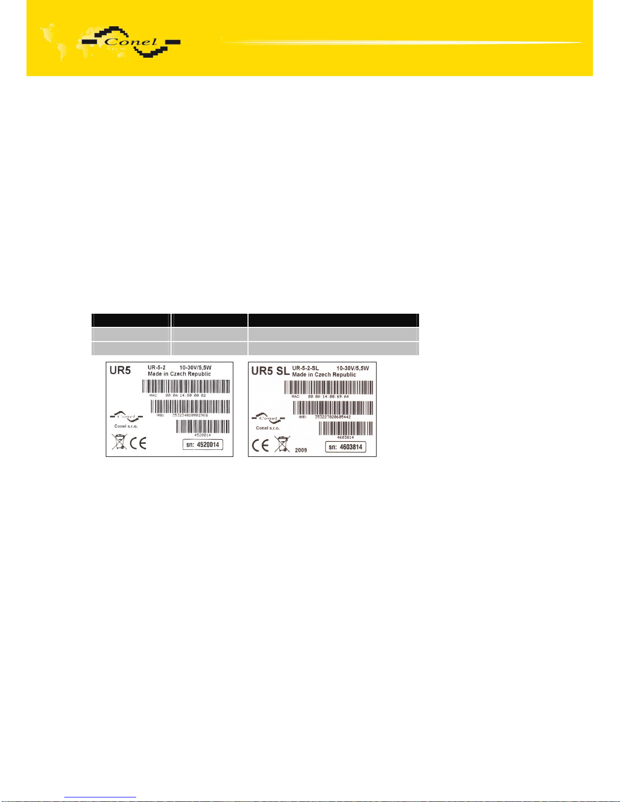
Specimen Label:
Trade name Type name Other
UR5 UR-5-2 Basic version
UR5 SL UR-5-2-SL Version in the aluminum box
Page 8
EXPANSION PORT MOUNTING
8
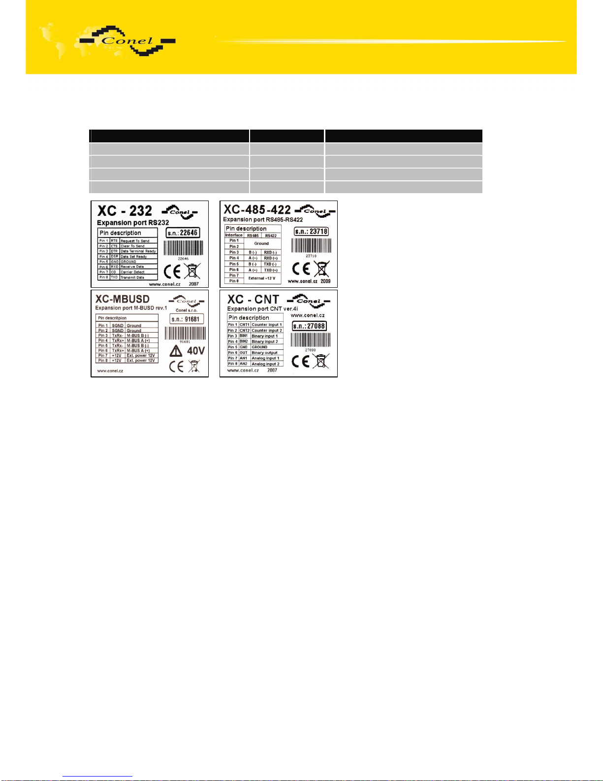
Example of expansion port PORT1:
Trade name Type name Power supply
Expansion port RS232 XC-232 Internal power supply
Expansion port RS485-RS422 XC-485422 Internal/external power supply
Expansion port M-BUSD XC-MBUSD External power supply
Expansion port CNT XC-CNT Internal power supply
Page 9

EXPANSION PORT MOUNTING
9
Basic delivered set of router includes:
• UMTS router,
• power supply,
• crossover UTP cable,
• external antenna,
• plastic clips for the DIN rail with fixing screws,
• installation CD containing instructions.
In addition to the basics it is possible to deliver:
• expansion port RS232, RS485/RS422, M-BUSD or CNT (separation columns are
in distribution),
• adapter for use of a second SIM card.
The router standard designed for:
• mounting to a panel using through holes (only UR5 version),
• possibility to be put on a work surface,
• for mounting onto a DIN rail, the plastic clips are included.
2.5. Antenna Connection
The antenna is connected to the router using the FME connector on the back panel.
External antennas:
Page 10

EXPANSION PORT MOUNTING
10
2.6. SIM Card Reader
The SIM card reader for 3 V and 1.8 V SIM cards is located on the front panel
of the router, there is possibility inside the router in case of adapter for the second SIM card.
To initiate the router into operation it is necessary to insert an activated SIM card with
unblocked PIN in the reader. The SIM cards might be of different adjusted APN (Access Point
Name).
2.7. Power Supply
The router requires +10 V DC to +30 V DC supply. Protection against reversed polarity
without signaling is built into the router.
The power consumption during receiving is 1W. The peak power consumption during
data sending is 3.5W. For correct operation it is necessary that the power source is able to
supply a peak current of 500mA.
2.8. Technical parameters
HSDPA/UMTS/EDGE/GPRS module
Complies with standards EN 301 511, v9.0.2,
EN 301 908-1&2, v3.2.1,
ETSI EN 301 489-1 V1.8.1,
EN 60950-1:06 ed.2 +A11:09
HSDPA parameters 3GPP rel. 5 standard
bitrate 3.6 Mbps/384 kbps
UE CAT. 1 to 6, 11, 12
Data compress 3GPP TS25.212
UMTS parameters W-CDMA FDD standard
PS bitrate – 384/384 kbps
CS bitrate – 64/64 kbps
GPRS parameters GPRS multislot class 10, CS 1 to 4
EGPRS multislot class 10, CS 1 to 4,
MCS 1 to 9
Transmit power Class 3 (+23dBm) for UMTS 900/2100MHz
Temperature range Function
Storage
-30 oC to +60 oC
-40 oC to +85 oC
Protection Freely
In switch board
IP20
IP56
Supply voltage 10 to 30 V DC
Consumption Reception
GPRS
UMTS/HSDPA
300 mW
to 3,5 W (GPRS transmission)
to 5,5 W (UMTS/HSDPA transmission)
Dimensions 30x90x102 mm (DIN 35mm)
Weight 150 g
Antenna connector FME – 50 Ohm
User interface ETH
USB
PORT1
Ethernet (10/100 Mbit/s)
USB 1.1 type A host
Optional RS232/RS485/M-BUSD
or inputs/outputs (I/O)
Page 11

EXPANSION PORT MOUNTING
11
2.9. Description of the individual components of the router
2.9.1. UMTS module
The UMTS module is used for HSDPA/UMTS/EDGE/GPRS UMTS network wireless
communication. It is integrated in the printed circuit board. The slide-out SIM card reader is
accessible from the front panel. The FME antenna connector is accessible from the back
panel.
UMTS Module
• Communicates in UMTS band 900/2100 MHz
• CS bitrate – 64/64 kbps
• PS bitrate – 384/384 kbps
• Supports W-CDMA FDD (Wideband - Code Division Multiple Access Frequency Division
Duplex) standard
2.9.2. Control microcomputer
The core of the router is a 32-bit microprocessor with 16 MB RAM, 4 MB FLASH
EEPROM, serial interface RS-232 and an Ethernet interface 10/100 Mbit/s.
The microcomputer is connected to the UMTS OEM module through the USB interface and
controls the communication via HSDPA/UMTS/EDGE/GPRS. Towards to the user it is
connected on the Ethernet interface.
The software is built on the uClinux operating system.
The router support services as like DHCP, NAT, GRE, IPsec tunnels, etc.
The modem settings are saved in the FLASH EEPROM memory. All modem
configurations can be done through a web interface (HTTP), which is protected by security
password.
Actual firmware version: 2.1.0 (22.4.2011)
Page 12
EXPANSION PORT MOUNTING
12
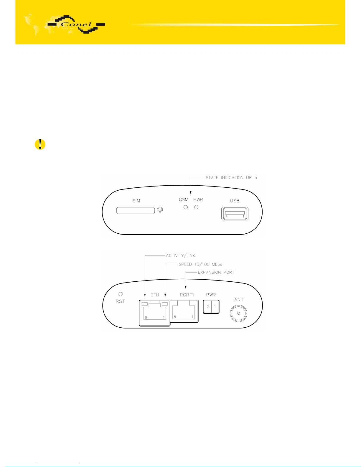
2.10. User interfaces (Connectors)
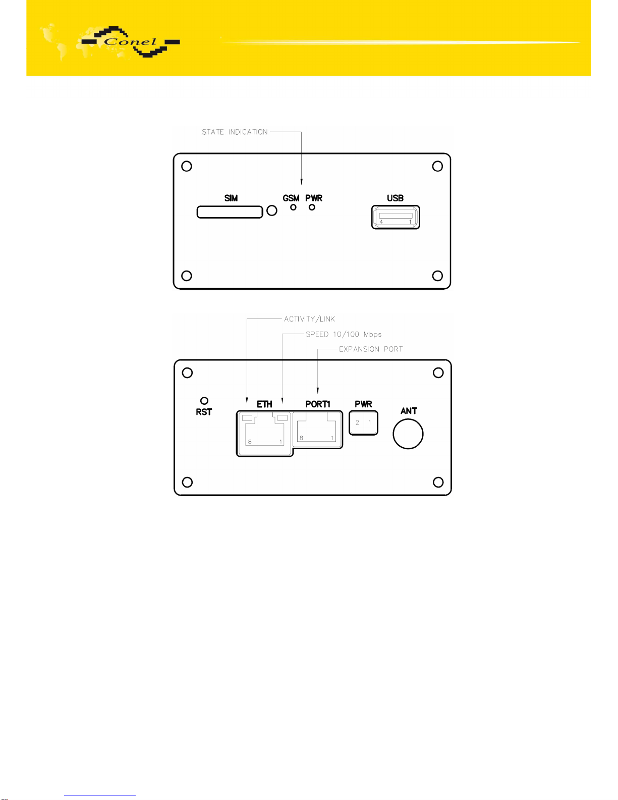
On the front and back panel of router the following connectors are located:
• one RJ12 or MRT9 connector (PWR) – for connection of the power supply adapter,
• one RJ45 connector (ETH) – for connection into the local equipment,
• one RJ45 connector (optional PORT1) – for connection of the local any arrangement over
RS232, RS485/422, M-BUSD or CNT,
• one FME or SMA connector (ANT) – for connection of the antenna,
• one USB-A Host connector (USB) – for connection of the devices to the router, USB
supports equipments with PL-2303 and FTDI USB/RS232 converter.
Front panel UR5
Rear panel UR5
Page 13
EXPANSION PORT MOUNTING
13
Front panel UR5 SL
Rear panel UR 5SL
Page 14
EXPANSION PORT MOUNTING
14
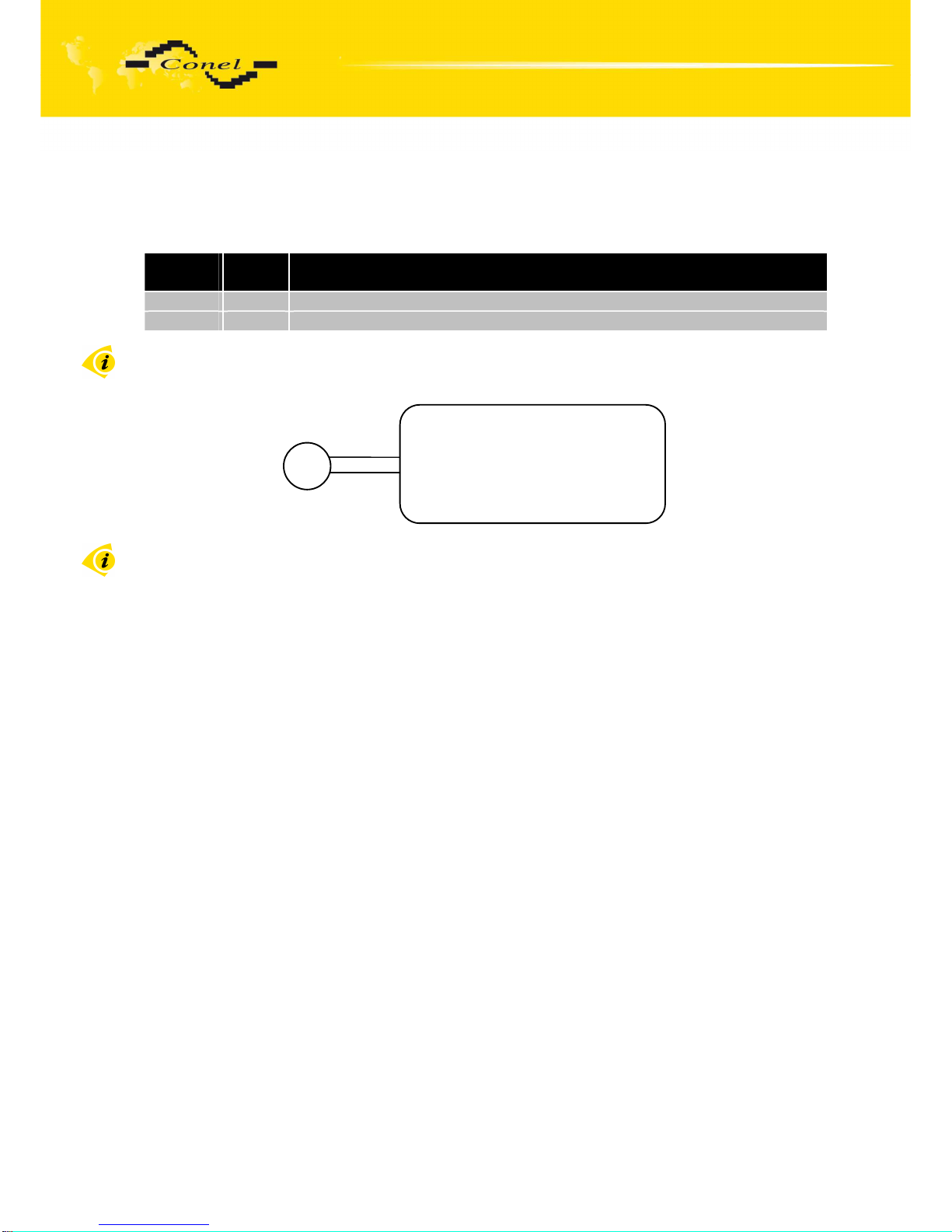
2.10.1. Connection of the PWR Supply Connector
Panel socket MRT9.
Pin
number
Signal
mark
Description
1 +UN Positive pole of DC supply voltage (+10 to +30 VDC)
2 GND Negative pole of DC supply voltage
Circuit example:
The positive pole +UN is marked by a red socket on the power supply.
Pin 1 – +UN
Pin 2 – GND
Router
DC
+
Page 15
EXPANSION PORT MOUNTING
15
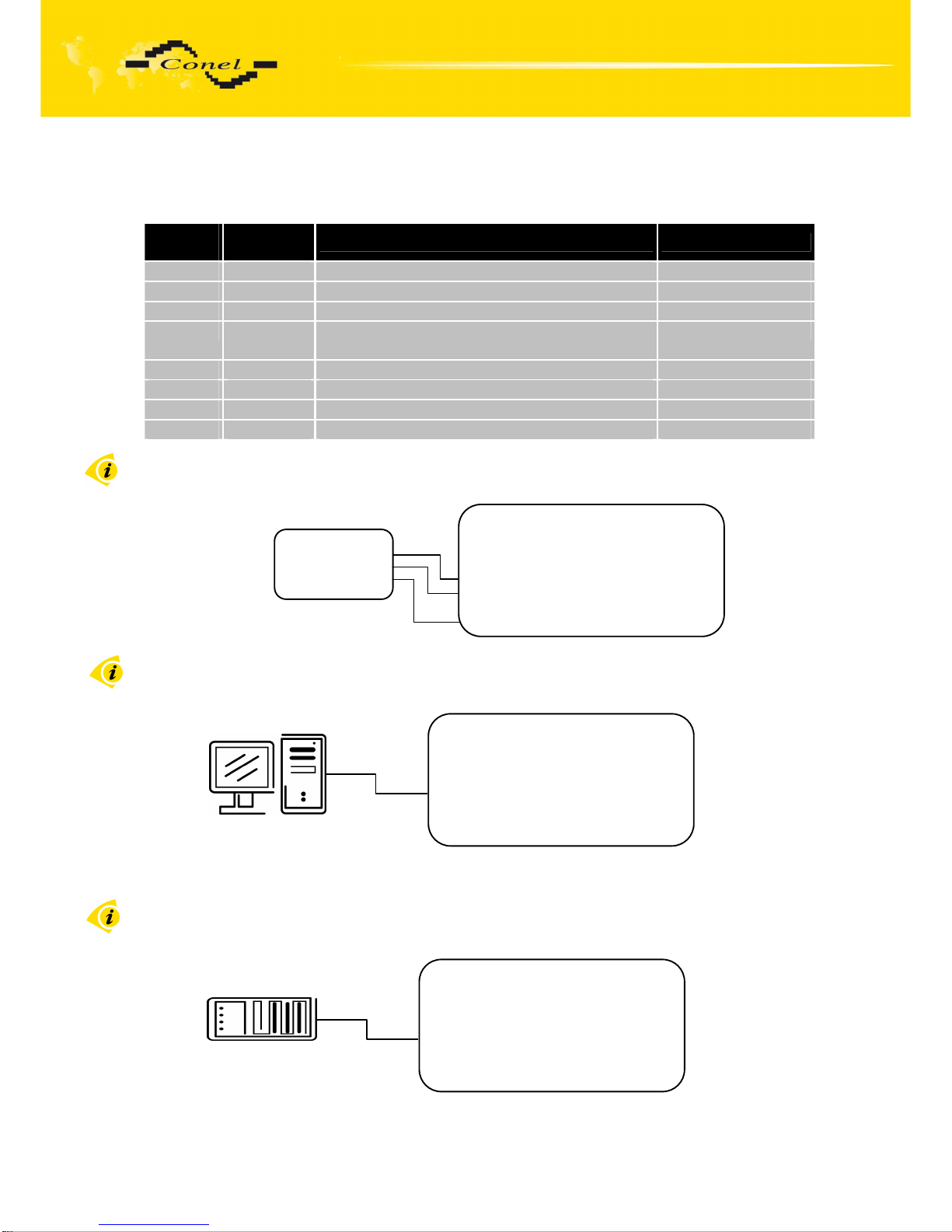
2.10.2. Connection of the Port1 Connector – RS232
Panel socket RJ45 (RS232 – DCE – Data Communication Equipment).
Pin
number
Signal
mark
Description Data flow direction
1 RTS Request To Send Input
2 CTS Clear To Send Output
3 DTR Data Terminal Ready Input
4 DSR Data Set Ready – connected to +4 V through
330 Ohm
Output
5 GND GROUND – signal ground
6 RXD Receive Data Output
7 CD Carrier Detect Output
8 TXD Transmit Data Input
Circuit example:
The router connection to the PC:
•
cable KD2 is connected to serial port PC (example COM1)
The router connection to equipment with full-value RS232 interface:
Router
ETH
PORT1
PWR
Cable KD-2
Router
ETH
PORT1
PWR
Cable KD-2
Pin 1 – RTS
Pin 2 – CTS
Pin 3 – DTR
Pin 4 – DSR
Pin 5 – GND
Pin 6 – RXD
Pin 7 – CD
Pin 8 – TXD
Router
Meter
GND
RXD
TXD
Page 16
EXPANSION PORT MOUNTING
16
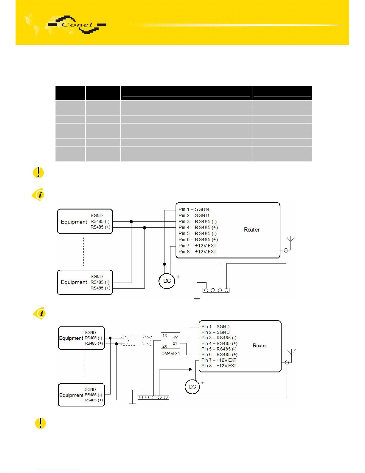
2.10.3. Connection of the Port1 Connector – RS485
Panel socket RJ45.
Pin
number
Signal
mark
Description Data flow direction
1 GND Signal and supply ground
2 GND Signal and supply ground
3 TxRx- RS485 B (-) Input/Output
4 TxRx+ RS485 A (+) Input/Output
5 TxRx- RS485 B (-) Input/Output
6 TxRx+ RS485 A (+) Input/Output
7 +12 V EXT External power supply
8 +12 V EXT External power supply
ATTENTION! Power supply is selected on the expansion port RS485 by help
of a jumper, 2.11. If galvanic separation is required the converter must have an external
power supply.
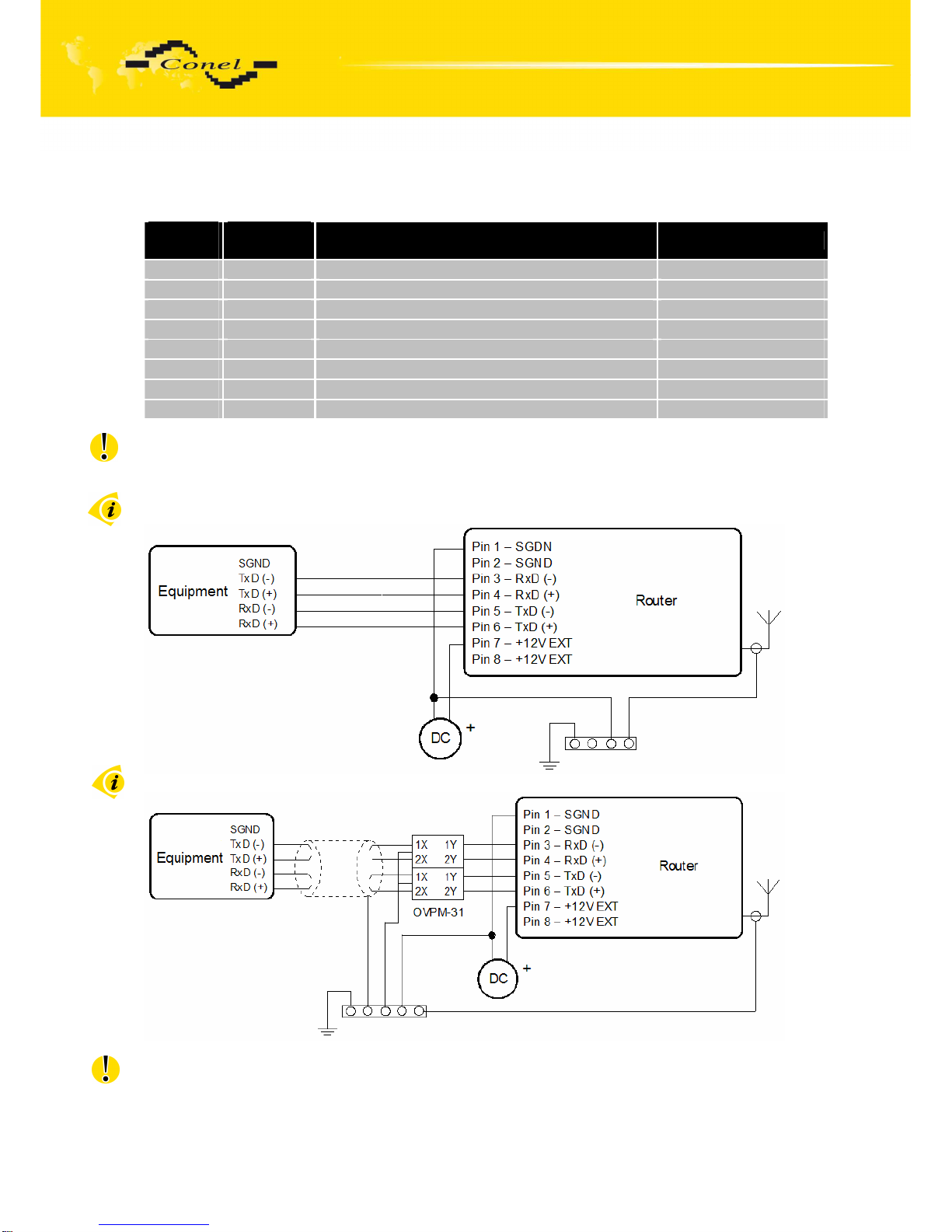
Circuit example of the equipment with a router with data cable length less than 10 m:
Circuit example of the equipment with a router with data cable length more than 10 m:
With a RS485 data cable more than 10m it is necessary to use overvoltage protection
on the router side!
Page 17
EXPANSION PORT MOUNTING
17
2.10.4. Connection of the Port1 Connector – RS422
Pin
number
Signal
mark
Description Data flow direction
1 SGND Signal and power supply ground
2 SGND Signal and power supply ground
3 RxD- Receive Data (-) Output
4 RxD+ Receive Data (+) Output
5 TxD- Transmit Data (-) Input
6 TxD+ Transmit Data (+) Input
7 +12V EXT External power supply
8 +12V EXT External power supply
ATTENTION! Power supply is selected on the expansion port RS422 by help
of a jumper, 2.9. If galvanic separation is required the converter must have an external
power supply.
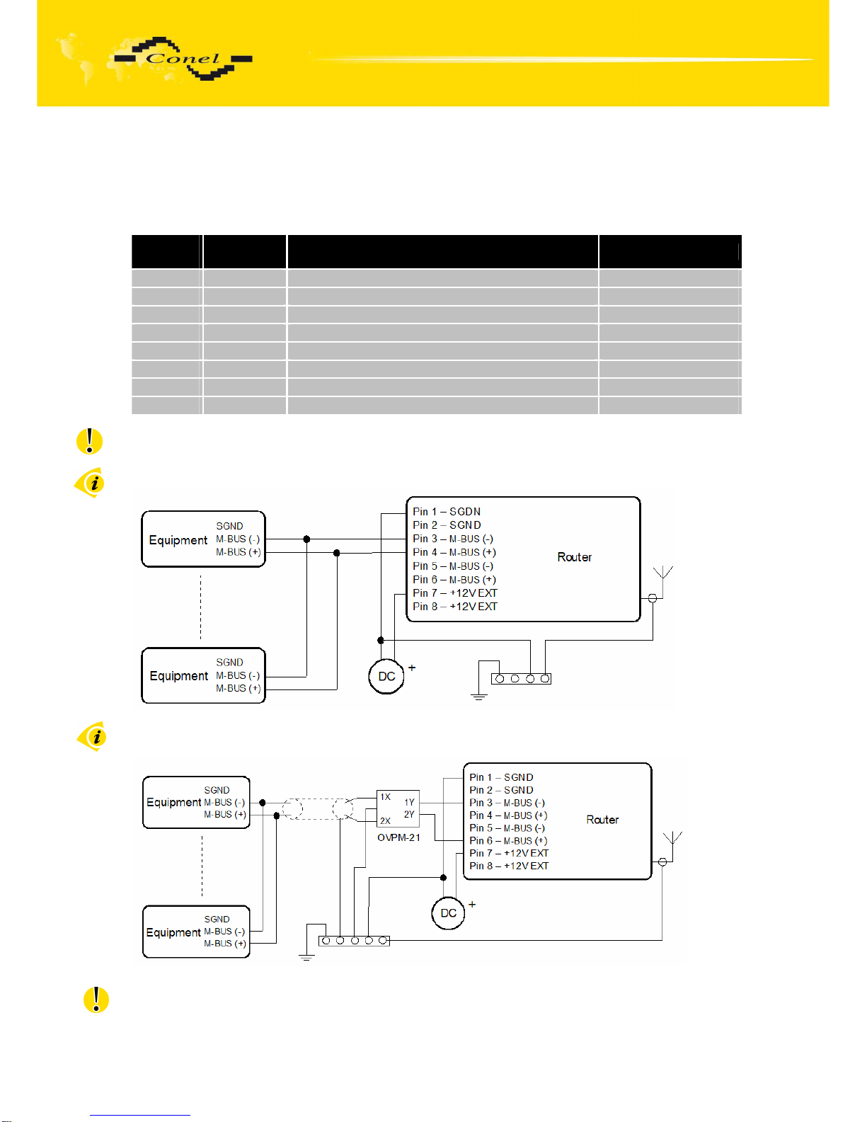
Circuit example of the equipment with router with data cable length less than 10 m:
Circuit example of the equipment with a router with data cable length more than 10 m:
With a RS422 data cable more than 10m it is necessary to use overvoltage protection
on the router side!
Page 18
EXPANSION PORT MOUNTING
18
2.10.5. Connection of the Port1 Connector – M-BUSD
Panel socket RJ45.
Pin
number
Signal
mark
Description Data flow direction
1 GND Signal and supply ground
2 GND Signal and supply ground
3 TxRx- M-BUS B (-) Input/Output
4 TxRx+ M-BUS A (+) Input/Output
5 TxRx- M-BUS B (-) Input/Output
6 TxRx+ M-BUS A (+) Input/Output
7 +12 V EXT External power supply
8 +12 V EXT External power supply
ATTENTION! External supply is for converter M-BUSD!
If galvanic separation is required the converter must have external power supply.
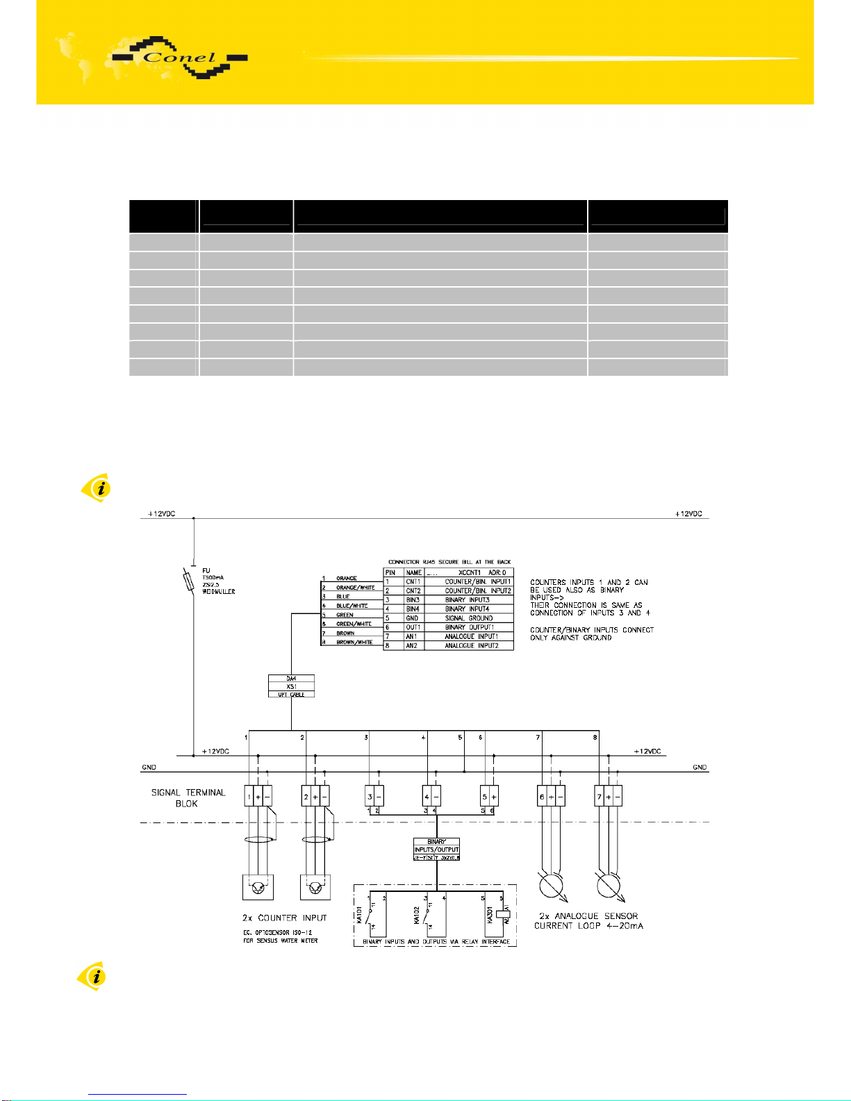
Circuit example of the equipment with a router with data cable length less than 10 m:
Circuit example of the equipment with a router with data cable length more than 10 m:
With a M-BUS data cable more than 10m it is necessary to use overvoltage protection
on the router side!
Page 19
EXPANSION PORT MOUNTING
19
2.10.6. Connection of the Port1 Connector – CNT
Panel socket RJ45.
Pin
number
Signal mark
Description Data flow direction
1 BIN1/CNT1 Binary input/counter input Input
2 BIN2/CNT2 Binary input/counter input Input
3 BIN3 Binary input Input
4 BIN4 Binary input Input
5 GND Signal ground
6 OUT1 Binary output (open collector) Output
7 AN1 Analogue input Input
8 AN2 Analogue input Input
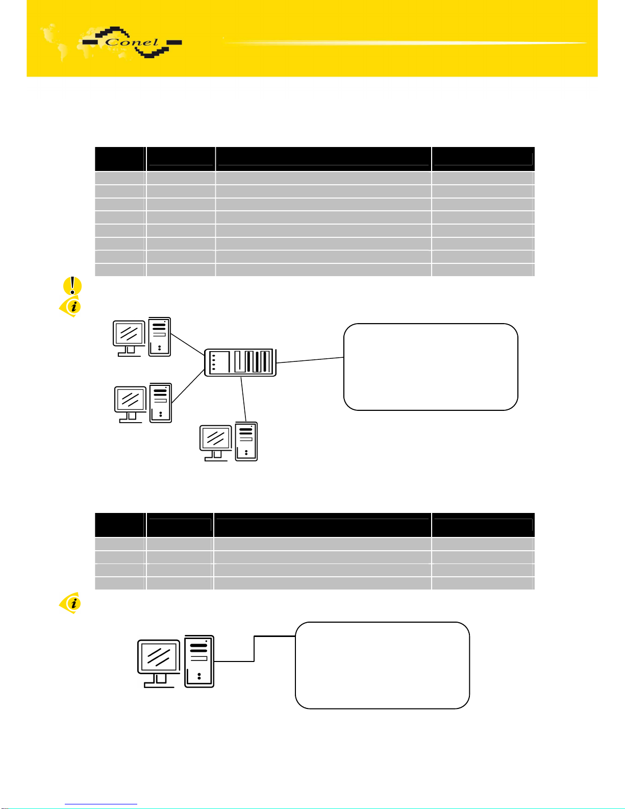
The user interface CNT is for monitoring and processing of analogue and binary signals and
to control (settings) of binary signals. Available are 2 counter and 2 binary inputs or 4 binary
inputs, 2 analogue inputs and 1 binary output. The settings of binaries and counter inputs by
the help of firmware in which the single input and output is defined. Binary output is not
switched to ground by default.
Typical connection of the router measuring circuits:
The router does not support to modify any signals of the CNT port, for example logical
functions.
Page 20
EXPANSION PORT MOUNTING
20
2.10.7. Connection of the ETH Connector
Panel socket RJ45.
Pin
number
Signal mark
Description Data flow direction
1 TXD+ Transmit Data – positive pole Input/Output
2 TXD- Transmit Data – negative pole Input/Output
3 RXD+ Receive Data – positive pole Input/Output
4 --- ---
5 --- ---
6 RXD- Receive Data – negative pole Input/Output
7 --- ---
8 --- ---
ATTENTION! Port ETH is not POE (Power Over Ethernet) compatible!
The ETH router connection:
2.10.8. Connection of the Connector USB
Panel socket USB-A.
Pin
number
Signal mark
Description Data flow direction
1 VCC Positive pole of 5V DC supply voltage
2 USB data - USB data signal – negative pole Input/Output
3 USB data + USB data signal – positive pole Input/Output
4 GND Negative pole of DC supply voltage
The USB router connection:
Router
USB
ETH
PORT1
PWR
USB cable A-B
Router
USB
ETH
PORT1
PWR
UTP cable
Switch
Page 21
EXPANSION PORT MOUNTING
21
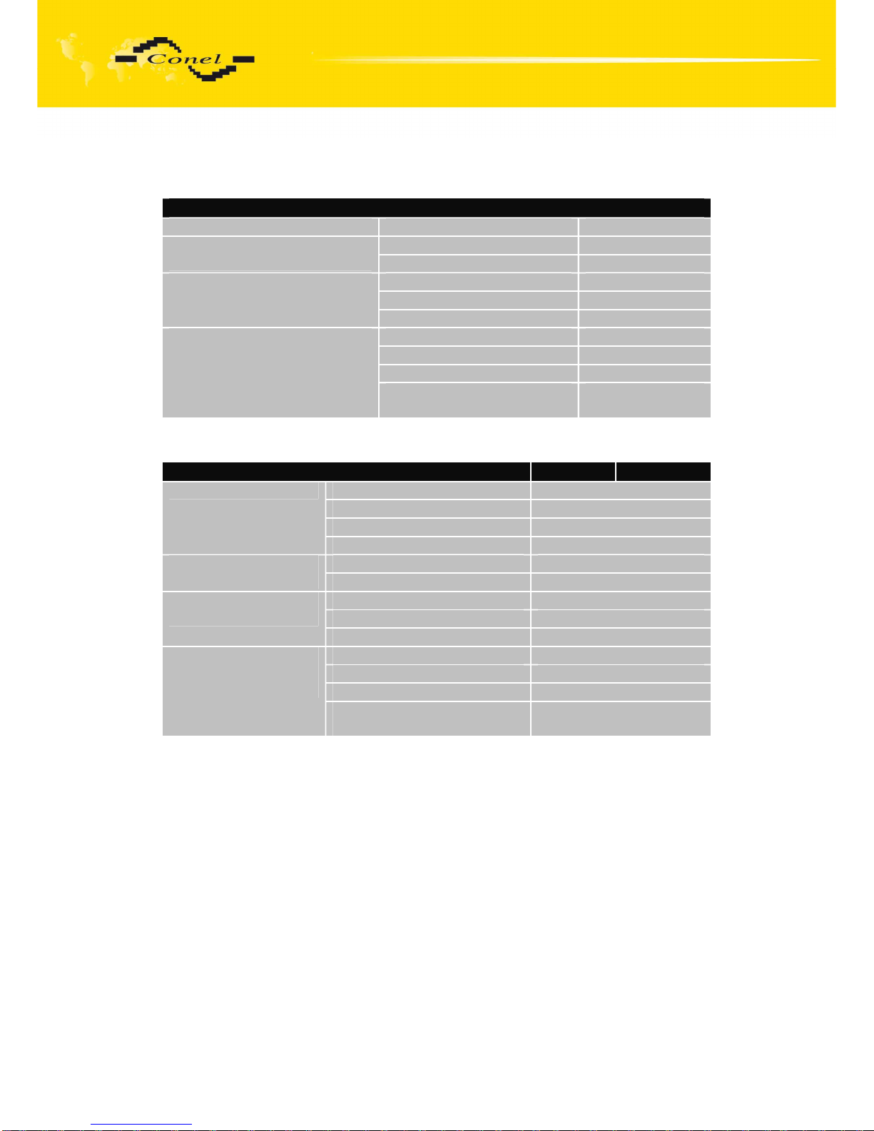
2.11. Technical specification of optional PORT1
• Expansion port RS232
Expansion port RS232
Power supply Internal ....
Operating temperature -20 .. +55 °C Environment
Storage temperature -20 .. +85 °C
Emission EN 55022/B
Immunity ETS 300 342
Standards
Safety EN 60950
Max. operating bus current 15 mA
Max. bit rate 230400 bps
Max. overvoltage ±30 V
RS232 specifications
(EN 1434)
Max. total cable length
(300Bd, 200nF/km)
20 m
• Expansion port RS485-RS422
Expansion port RS485-RS422 RS485 RS422
External +10 .. +30 V
Internal ....
Supply power Max. 1 W
Power supply
Supply current Max. 4 mA
Operating temperature -20 .. +55 °C Environment
Storage temperature -20 .. +85 °C
Emission EN 55022/B
Immunity ETS 300 342
Standards
Safety EN 60950
Max. devices (each 1,5 mA) 256
Max. bit rate 38400 bps
Short circuit strength Permanent
RS485 specifications
(EN 1434)
Max. total cable length
(300Bd, 200nF/km)
1200 m
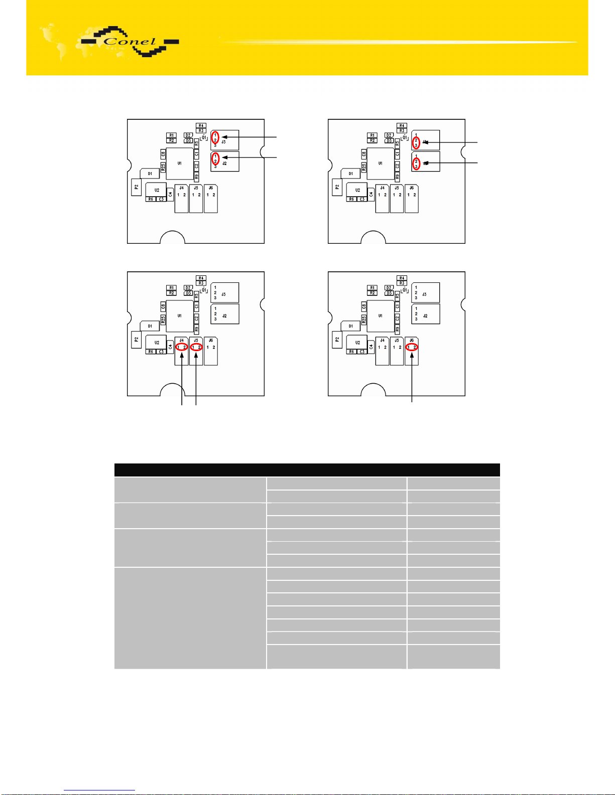
External or internal power supply of module Expansion port RS485/RS422 can be
made by wiring jumpers J2 and J3 on this module. If external power supply of the module is
required, jumpers J2 and J3 must be connected to pins 2 - 3. Internal power supply is made
by connecting pins 1 - 2 with jumpers J2 and J3.
Interface behaviour of module Expansion port RS485/RS422 can be made by wiring
jumpers J4, J5 and J6 on this module. If RS485 is required, jumpers J4 and J5 must be
connected and jumper J6 disconnected. If RS422 is required, jumpers J4 and J5 must be
disconnected and jumper J6 connected.
Jumper placement can be seen in the picture below (module Expansion port
RS485/RS422 from TOP layer). We recommend that internal power supply is only chosen in
the event that it is not possible to ensure external power supply. If internal power supply is
chosen, converter RS485/RS422 is not galvanic separated.
Page 22
EXPANSION PORT MOUNTING
22
The jumper circuitry for internal supply The jumper circuitry for external supply
The jumper circuitry for RS485 The jumper circuitry for RS422
• Expansion port M-BUSD
Expansion port M-BUSD
Voltage +10 .. +30 V Power supply
Supply power Max. 4 W
Operating temperature -20 .. +55 °C Environment
Storage temperature -20 .. +85 °C
Emission EN 55022/B
Immunity ETS 300 342
Standards
Safety EN 60950
Max. devices (each 1,5 mA) 30
Max. operating bus current 60 mA
Overload detection 100 mA
Short circuit strength Permanent
Bus voltage mark 36 .. 43 V
Bus voltage space 24 .. 31 V
M-BUS specifications
(EN 1434)
Max. total cable length
(300Bd, 200nF/km)
1000 m
Jumper J2
Jumper J3
Jumper J2
Jumper J3
Jumpery J4 a J5
Jumper J6
Page 23
EXPANSION PORT MOUNTING
23
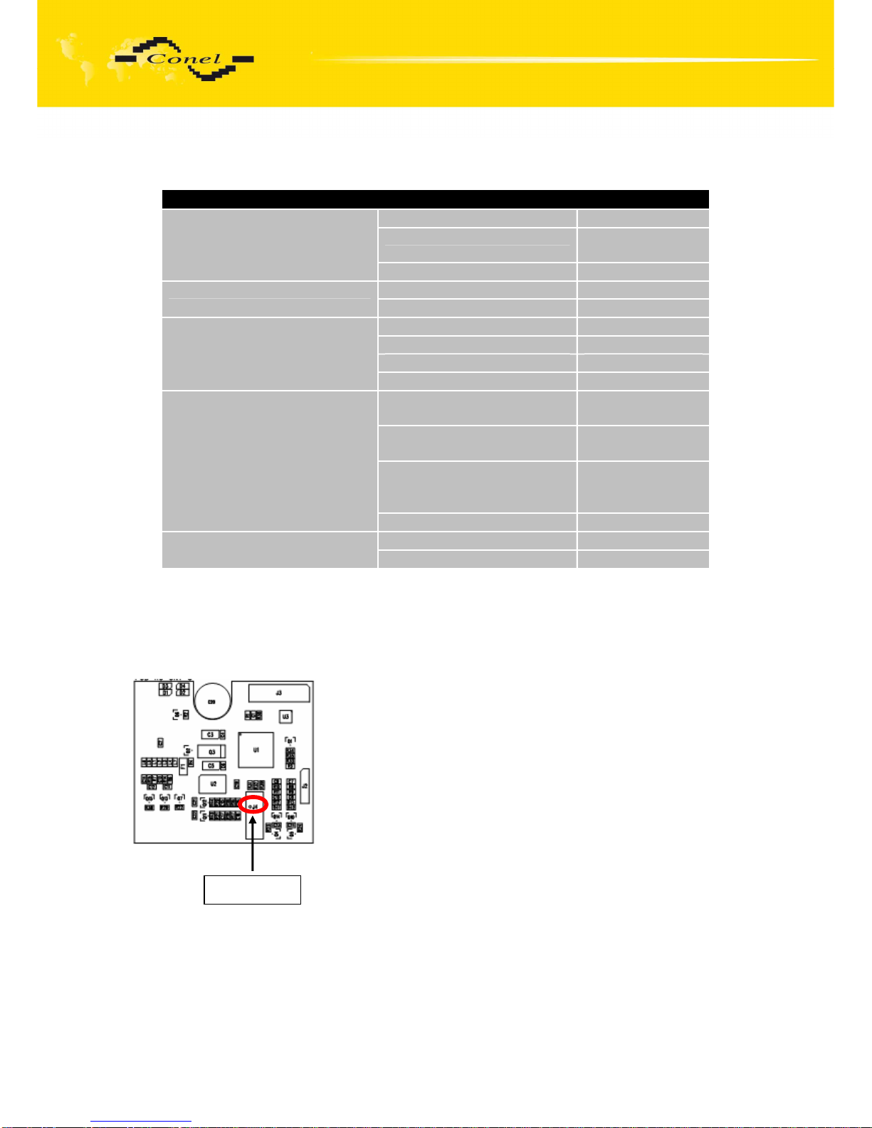
• Expansion port CNT
Expansion port CNT
Internal ….
Sleep 100 µA (counter
is functional)
Power supply
Operation 2 mA
Operating temperature -20 .. +55 °C Environment
Storage temperature -20 .. +85 °C
Emission EN 55022/B
Immunity ETS 300 342
Safety EN 60950
Standards
Isolation EN 60747
2x counter Max. 100 Hz,
ratio max. 1:10
2x analogue inputs 0 .. 20 mA,
Rin 100 Ohms
2x binary inputs reed contact
is J4 – 20mA
is not J4 - 8µA
Inputs/Outputs
1x output (open collector) 100 mA
Voltage resistance Permanent Others
Sleeping mode Controlled
If active level is set as log. 1, electric current can be selected with jumper. When
jumper J4(viz. picture) is mounted on pins, electric current value is 20 mA. When jumper J4
is not mounted, electric value is 8µA. If current value is 20mA, CNT has higher consumption,
also it has higher resistance to industrial noise.
Jumper J4
Page 24

EXPANSION PORT MOUNTING
24
2.12. Modem status indication
On the front and back panel of the modem there are altogether four LED indicators,
which inform on the modem status.
Panel Color Description
Description
Front Green PWR
Blinking 1:9 ................... join connection
Blinking 9:1 ................... establishing of connection
Permanently on ……….. starting of the router
Front Red GSM Blinking ……….. communication in progress
Back Green –
On ...................... selected 100 Mbit/s
Off ...................... selected 10 Mbit/s
Back Green –
On........................ the network cable is connected
Blinking ……….... data transmission
Off ....................... the network cable is not connected
2.13. Putting into operation
Before putting the UR5 or UR5 SL router into operation it is necessary to connect all
components needed for the operation of your applications and the SIM card must be inserted
(the modem is off).
The modem is put into operation by connection of the power supply to the modem.
In the default setting the modem starts to login automatically to the preset APN. The behavior
of the modem can be modified by means of the web interface which is described
in the following chapter.
Page 25
EXPANSION PORT MOUNTING
25
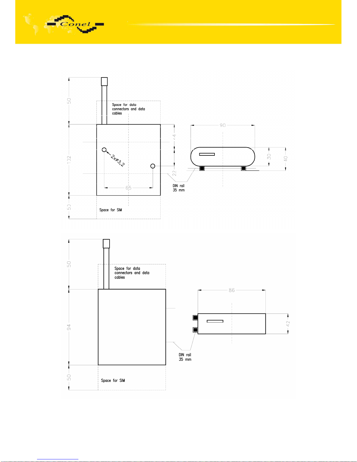
2.14. Mechanical external dimensions and mounting recommendations
For the majority of applications with a built-in modem in a switch board it is possible to
recognize two sorts of environments:
Page 26
EXPANSION PORT MOUNTING
26
•
no public and industry environment of low voltage with high interference,
•
public environment of low voltage without high interference.
For both of these environments it is possible to mount modems to a switch board,
the following there is no need to have examination immunity or issues in connection with
EMC according to EN 60439-1 ed.2:00 + A1:04.
For compliance of EN 60439-1 ed.2:00 + A1:04 specification it is necessary to
observe next assembly of the modem to the switch - board:
•
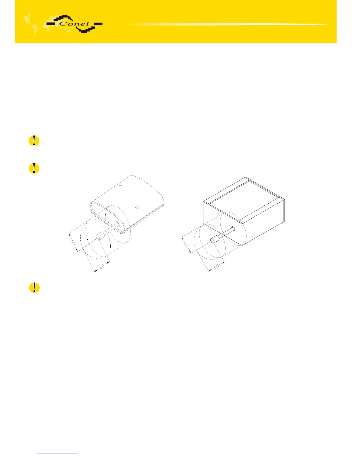
for round antennas we recommend to observe a distance of 6 cm from cables and
metal surfaces on every side according to the next picture due to the elimination of
interference, while using an external antenna except for the switch-board it is
necessary to fit a lightening conductor,
•
before mounting a modem on sheet-steel we recommend using an external antenna,
•
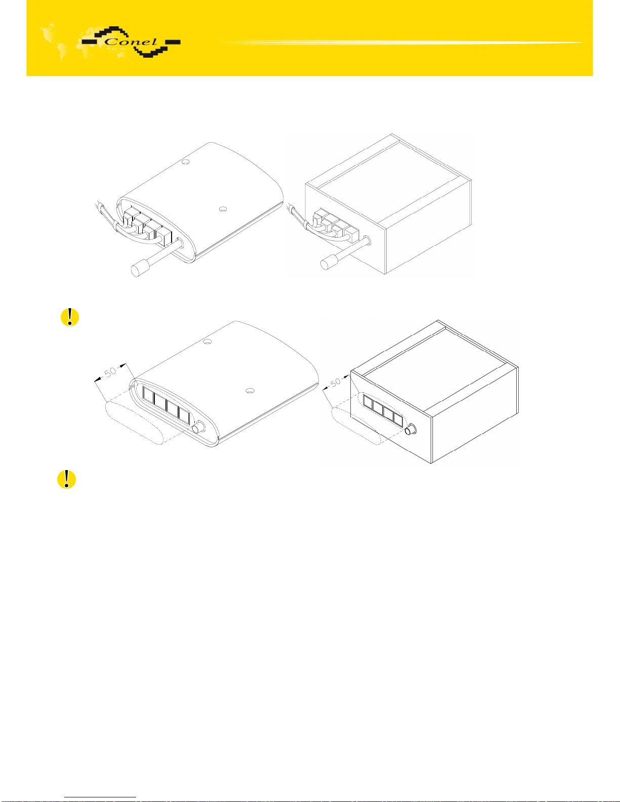
for single cables we recommend to bind the bunch according to the following picture,
for this use we recommend:
length of the bunch (combination of power supply and data cables) can
be maximum 1,5 m, if the length of data cables exceeds 1,5 m or in the
event of, the cable leads towards the switch - board, we recommend
installing over - voltage protectors (surge suppressors),
with data cables they mustn't carry cables with reticular tension
~ 230 V/50 Hz,
Page 27
EXPANSION PORT MOUNTING
27
all signals to sensors must be twisted pairs.
•
sufficient space must be left before individual connectors for handling of cables,
•
for correct function of the modem we recommend to use in the switch-board earth-
bonding distribution frame for grounding of power supply of modem, data cables and
antenna,
Page 28
EXPANSION PORT MOUNTING
28
•
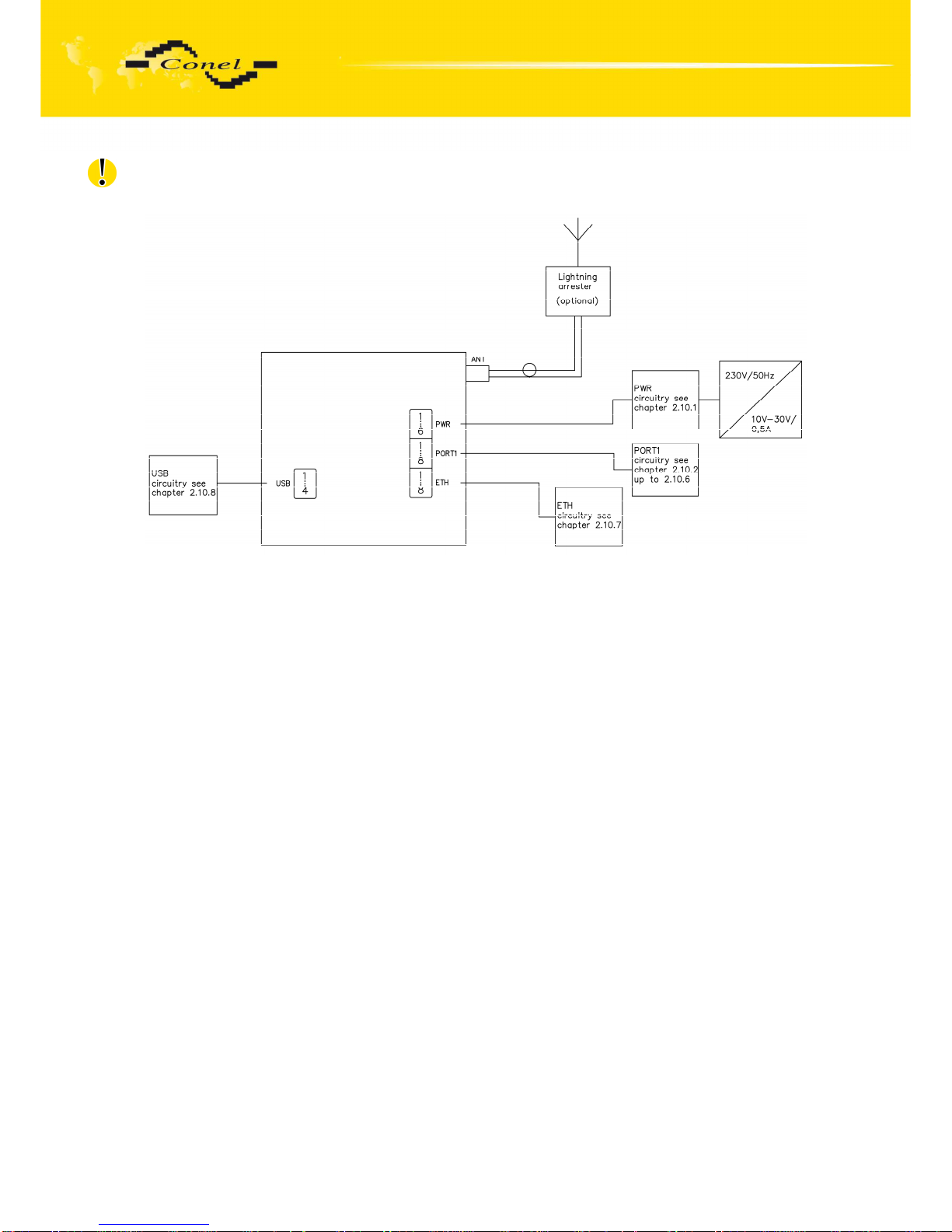
the circuit diagram of the modem is on the following pictures.
Page 29
EXPANSION PORT MOUNTING
29
3. Expansion port mounting
3.1. Expansion port mounting for UR5
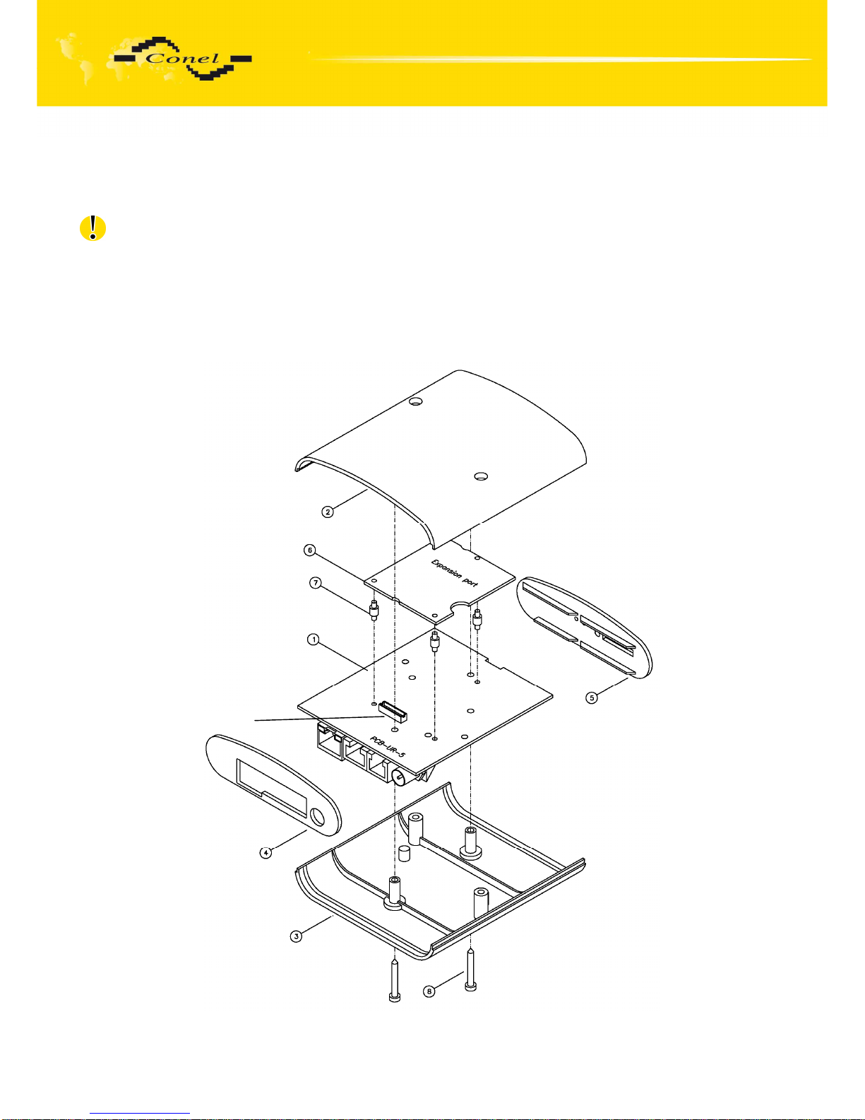
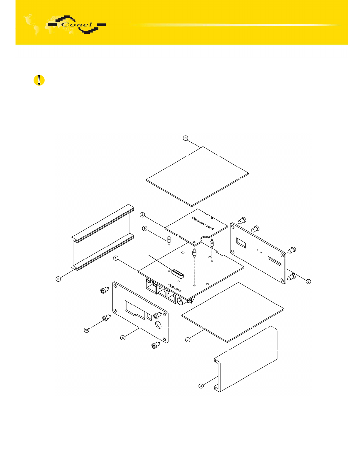
Attention! Expansion port PORT1 includes when the router UR5 is switched off.
After unscrewing two screws (position 8) on the box bottom part (position 3) and
removing box top part (position 2) the expansion port PORT1 (position 6) connects to
connector J3 (see below) of the router B-UR-5-2 motherboard (position 1) from the TOP side.
The expansion port is mounted to the motherboard by the help of three spacers (position 7).
After mounting the expansion port, the box is screwed together by the help of three screws
(position 8).
Connector J3
Page 30

EXPANSION PORT MOUNTING
30
Parts list and description
Part
Description Number
1 UMTS router UR 5-2 motherboard 1
2 UR 5 box top part 1
3 UR 5 box bottom part 1
4 UR 5 rear head 1
5 UR 5 front head 1
6 Expansion port 1
7 Spacers for expansion port PORT1 mounting to motherboard 3
8 Screw for box completion 2
Page 31
EXPANSION PORT MOUNTING
31
3.2. Expansion port mounting for UR5 SL
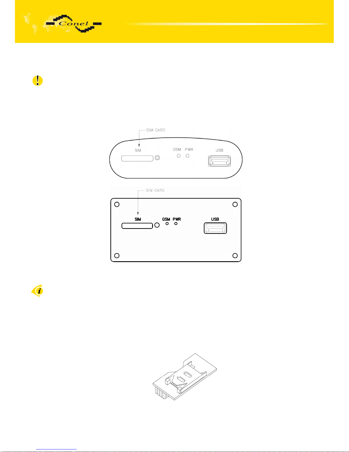
Attention! Expansion port PORT1 include when the router UR5 SL is switched off.
After unscrewing four screws (position 10) on the rear panel (position 5)
and removing it is possible to take out the B-UR-5-2 motherboard (position 1). The expansion
port PORT1 (position 2) is connected to connector J3 (see below) of the router B-UR-5
motherboard (position 1) from TOP side. The expansion port is mounted to the motherboard
by the help of three spacers (position 9). After mounting the expansion port the box is
screwed together by the help of four screws.
Connec
tor J3
Page 32

EXPANSION PORT MOUNTING
32
Parts list and description
Part
Description Number
1 UMTS router motherboard 1
2 Expansion port PORT1 1
3 Left box part 1
4 Right box part 1
5 Rear head 1
6 Front head 1
7 Bottom box part 1
8 Top box part 1
9 Spacers for expansion port PORT1 mounting to motherboard 3
10 Screw for box completion 8
Page 33
CHANGE OF THE SIM CARDS
33
4. Changing the SIM cards
Attention! Insert the SIM card when the router is switched off.
Changing the first SIM card:
Ensure that the modem is disconnected from the power supply. Press the small
yellow button next to the reader to eject the reader holder. Insert the SIM card into the reader
holder and slide it in the reader.
4.1. Changing the Second SIM card in the UR5 router
The second SIM card holder is can not be bought itself. If need to add the second
SIM card holder the router have to be send to Conel s.r.o. company.
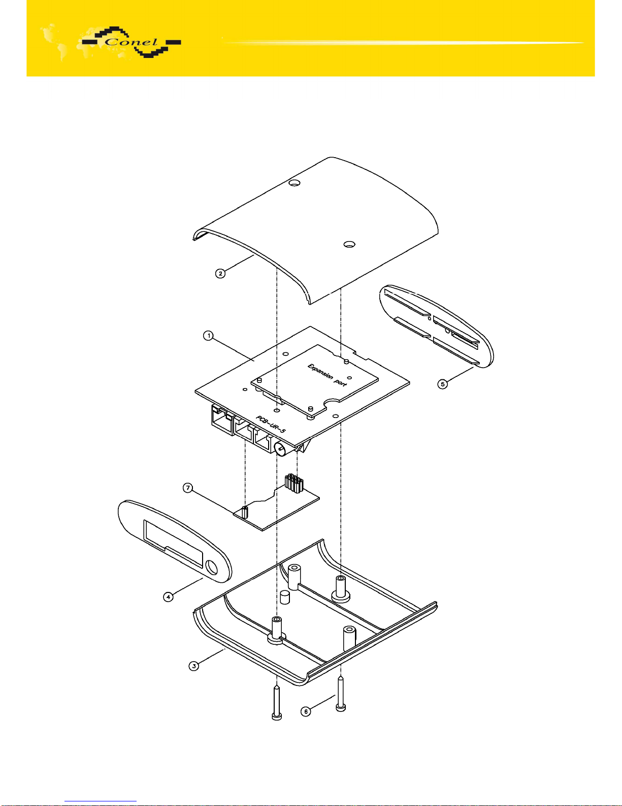
After unscrewing the two screws (position 6) on the box bottom part (position 3) and
removing the box top part (position 2) the second SIM card (position 7) is on the router B-UR5 motherboard (position 1) from the TOP side (see below). After mounting the second SIM
card the box is secured using the two screws (position 6).
Adapter for the second SIM card:
Page 34
CHANGE OF THE SIM CARDS
34
Mounting the second SIM socket
:
Page 35

CHANGE OF THE SIM CARDS
35
Parts list and description
Part
Description Number
1 UMTS router UR 5 motherboard 1
2 UR 5 box top part 1
3 UR 5 box bottom part 1
4 UR 5 rear head 1
5 UR 5 front head 1
6 Screw for box completion 2
7 Adapter for the second SIM card 1
4.2. Changing the second SIM card in the UR5 SL router
The second SIM card holder is can not be bought itself. If need to add the second
SIM card holder the router have to be send to Conel s.r.o. company.
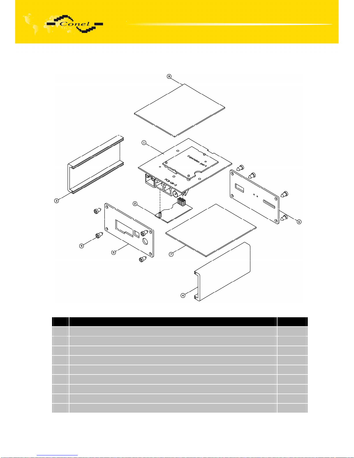
After unscrewing the four screws (position 9) on the rear head (position 5), and
removing it, it is possible to change the second SIM card (position 7) on the router B-UR-5
motherboard (position 1) from the TOP side (see below). After mounting the second SIM
card the box is secured using the four screws (position 9).
Adapter for the second SIM card:
Page 36
CHANGE OF THE SIM CARDS
36
Mounting the second SIM socket
:
Parts list and description
Part
Description Number
1 UMTS router UR5 motherboard 1
2 Adapter for the second SIM card 1
3 Left box part 1
4 Right box part 1
5 Rear head 1
6 Front head 1
7 Bottom box part 1
8 Top box part 1
9 Screw for box completion 8
Page 37
CONFIGURATION
37
5. Configuration setting over web browser
Attention! If the SIM card is not inserted in the router, then it is impossible to operate.
The inserted SIM card must have activated GPRS. Insert the SIM card when the router is
switched-off.
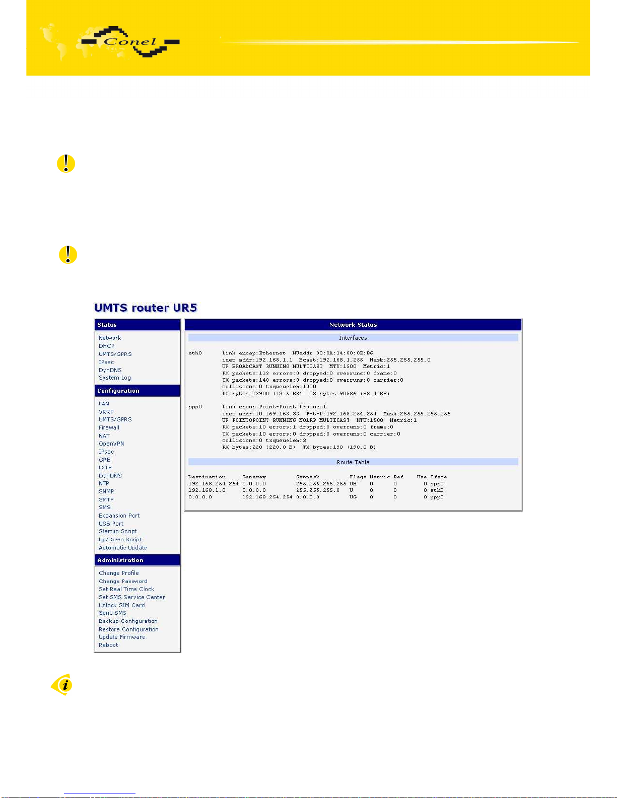
Monitoring of the status, configuration and administration of the router can
be performed by means of the web interface, which is available after insertion of IP address
of the modem into the web browser. The default IP address of the modem is 192.168.1.1.
Configuration may be performed only by the user "root" with initial password "root".
For providing higher security of your network we recommend changing this password!
More about changing password can be found in chapter 5.27.
The left part of the web interface contains the menu with pages for monitoring
of the Status, Configuration and Administration of the router.
After green LED starts to blink it is possible to restore initial settings of the router
by pressing button RST on front panel. After press button RST it is restoration of the
configuration and reset (green LED will be on).
5.1. Network Status
Page 38
CONFIGURATION
38
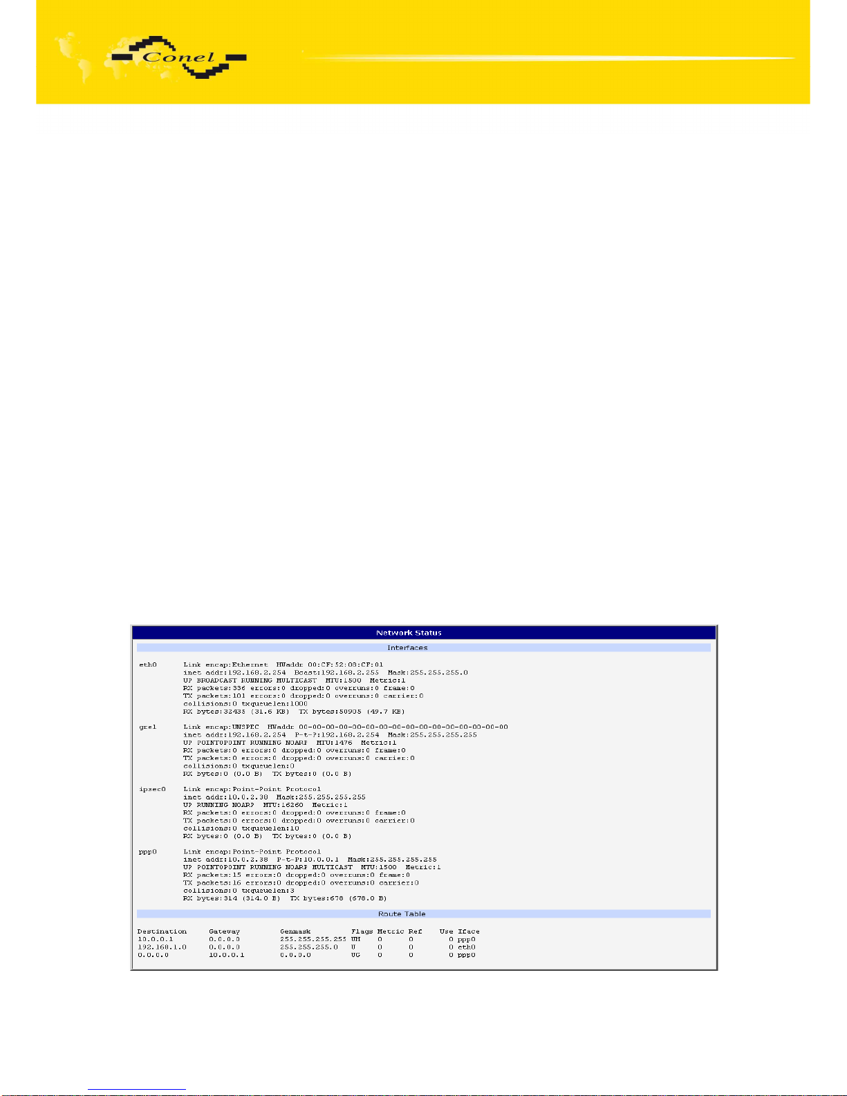
To view the system information about the modem operation, select
the System Information menu item. The bottom part of the window contains information about
the system memory usage. The upper part of the window displays detailed information about
active interfaces:
• eth0 – parameters of networks interface
• ppp0 – PPP interface (active connection to GPRS/EDGE)
• tun0 – OpenVPN tunnel interface
• gre1 – GRE tunnel interface
• ipsec0 – IPSec tunnel interface
By each of the interfaces is then shown the following information:
• HWaddr – hardware (unique) address of networks interface
• inet – own IP address
• P-t-P – IP address second ends connection
• Bcast – broadcast address
• Mask – mask of network
• MTU – maximum size of packet, which is equipment able transmit
• Metric – number of routers, over which packet must pass
• RX packets – received packets, errors – number of errors, dropped – dropped
packets
• TX packets – transmit packets, errors – number of errors, dropped – dropped packets
• collisions – number of collisions
• RX bytes – total number of received bytes
• TX bytes – total number of transmitted bytes
It is possible to elicit PPP connection state from the network information. If the PPP
connection is active, then it is in the system information shown as ppp0 connection.
Page 39
CONFIGURATION
39
5.2. DHCP Status
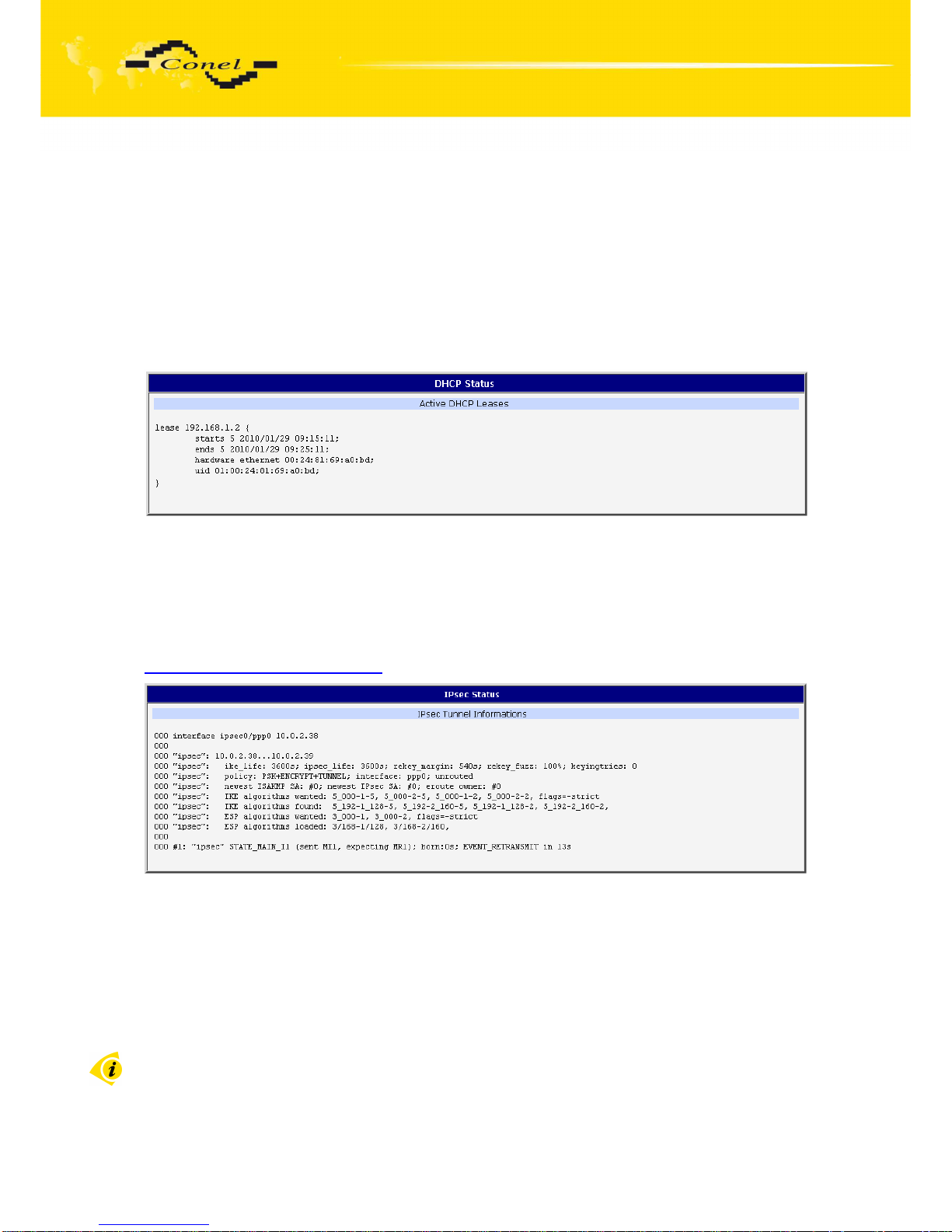
Information about IP addresses, which was leased to the router by the DHCP server,
is possible to find in menu in sum DHCP:
• lease 192.168.1.2 (generally IP address) – assigned IP address
• starts – information about time of assignation of IP address
• ends – information about time of termination IP address validity
• hardware ethernet – hardware MAC (unique) address
• uid – unique ID
In the extreme the DHCP status can display two records for one IP address. That
could have been caused by resetting of network cards.
5.3. IPsec status
Information on actual IPsec tunnel state can be called up in option IPsec in the menu.
Detailed information on the description shown below can be found on the following link
http://www.freeswan.org/doc.html.
5.4. UMTS/GPRS Status
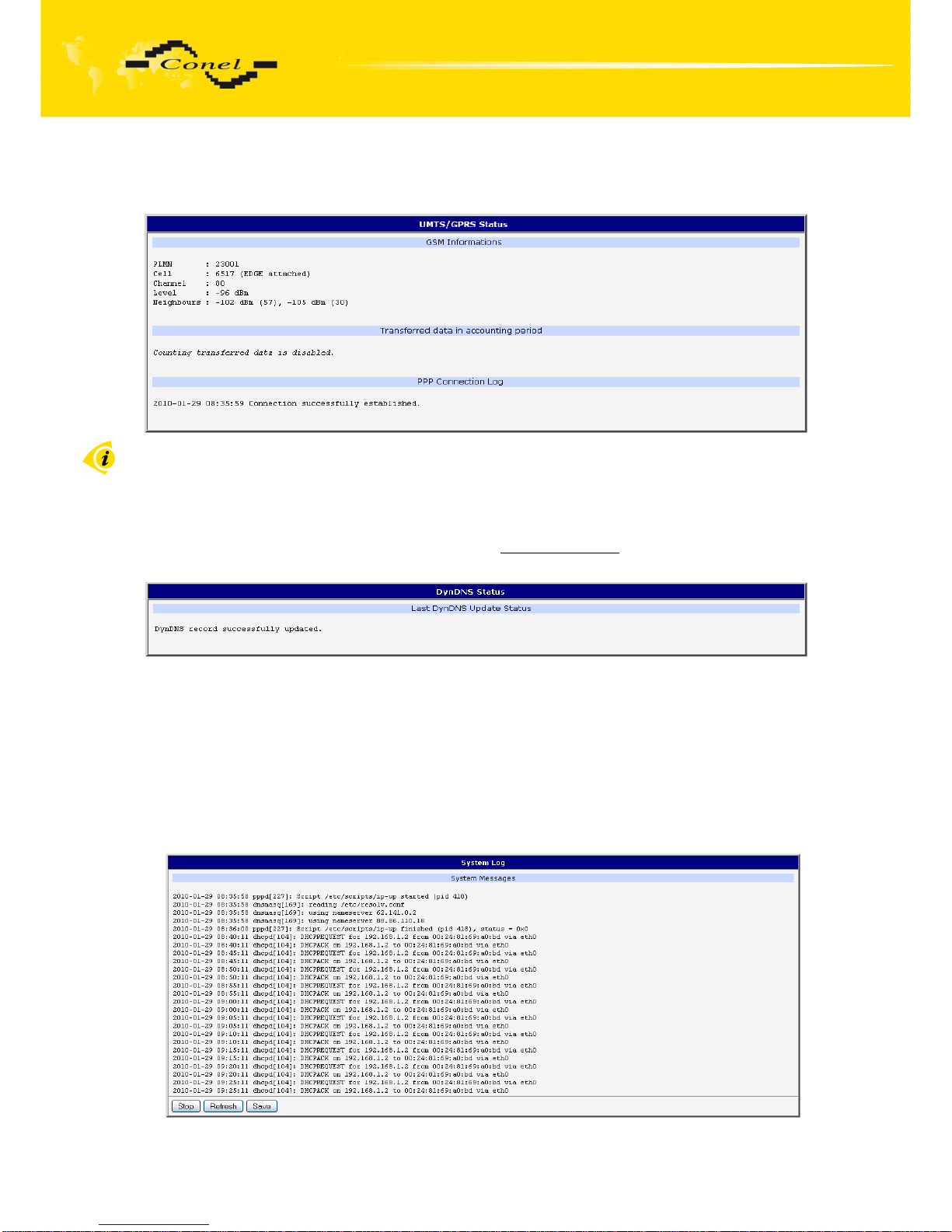
The item UMTS/GPRS in the menu contains up-to-date information about PLMN
(code of operator), cell, channel and signal quality of the selected cell, as well as neighboring
hearing cells. In the middle part of window is shows information about transferred data in
accounting period. The PPP Connection Log is in the bottom of this window where
information about the make-up of the PPP connection is and pertinent problems on this
formation.
Information about transferred data is show when the parameter Data Limit is set
(UMTS/GPRS configuration) and it set parameter (Switch to backup SIM card hen data limit
to exceeded); or when the parameter Data Limit is set (UMTS/GPRS configuration) and it set
Page 40
CONFIGURATION
40
parameter Send SMS when data limit is exceeded (SMS configuration). Information about
transferred data is show for primary SIM card only.
For the router with HC15 Cinterion module item UMTS/GPRS in the menu contains
up-to-date information about signal quality of the selected cell only.
5.5. DynDNS status
DynDNS up - dating entry result on server www.dyndns.org can be called up in option
DynDNS item in the menu.
5.6. System Log
In case of any problems with connection to GPRS it is possible to view the system log
by pressing the System Log menu item. The System log observes only connection to GPRS
and formation of IPsec tunnel. The upper part of the window displays possible errors at GPRS
connection establishment. After switching on the log daemon by pressing the Start button,
the bottom part of the window displays detailed reports from individual applications running
in the modem. To update the contents of the window press the Refresh button. By the help of
button Save it is possible to save the system log to the computer.
Page 41
CONFIGURATION
41
Program syslogd can be started with two options that modifies its behaviour. Option
"-S" followed by decimal number set maximal number of lines in one log file. Option "-R"
followed by hostname or IP address enable logging to remote syslog daemon. For starting
syslogd with these options you could modify script "/etc/init.d/syslog" or add lines "killall
syslogd" and "syslogd <options> &" into Startup Script.
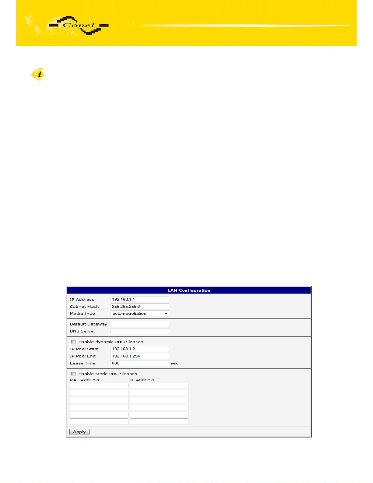
5.7. LAN Configuration
To enter the network configuration, select the LAN menu item. In the first part of
the window it is possible to define the network interface IP address (IP address), the network
mask (Subnet Mask) and media type (Media Type), in the majority of cases set Auto-
Negotiation.
In the second part of the window is possible to define Default Gateway and DNS
server.
In the third part of the window, it is possible to define the DHCP server by checking the
Enable dynamic DHCP server option. In the window it is possible to define the beginning
(IP Pool Start) and end (IP Pool End) of the pool of IP addresses which will lease to DHCP
clients. By parameter Lease time is possible to define time after which the client can use IP
address.
In the fourth part of the Windows it is possible, by checking the Enable static
DHCP server option, to define leases up to six static IP Addresses, which conform to MAC
Address of the connected equipment etc.
The changes in settings will apply after pressing the Apply button.
The DHCP server assign IP addresses to the connected clients from defined address
pool, IP address of the gate and IP address of the primary DNS server. It is important not to
overlap ranges of static engaged IP address with address allotted by the help of DHCP, or
collision of addresses may occur, thereby malfunctioning the network.
Page 42
CONFIGURATION
42
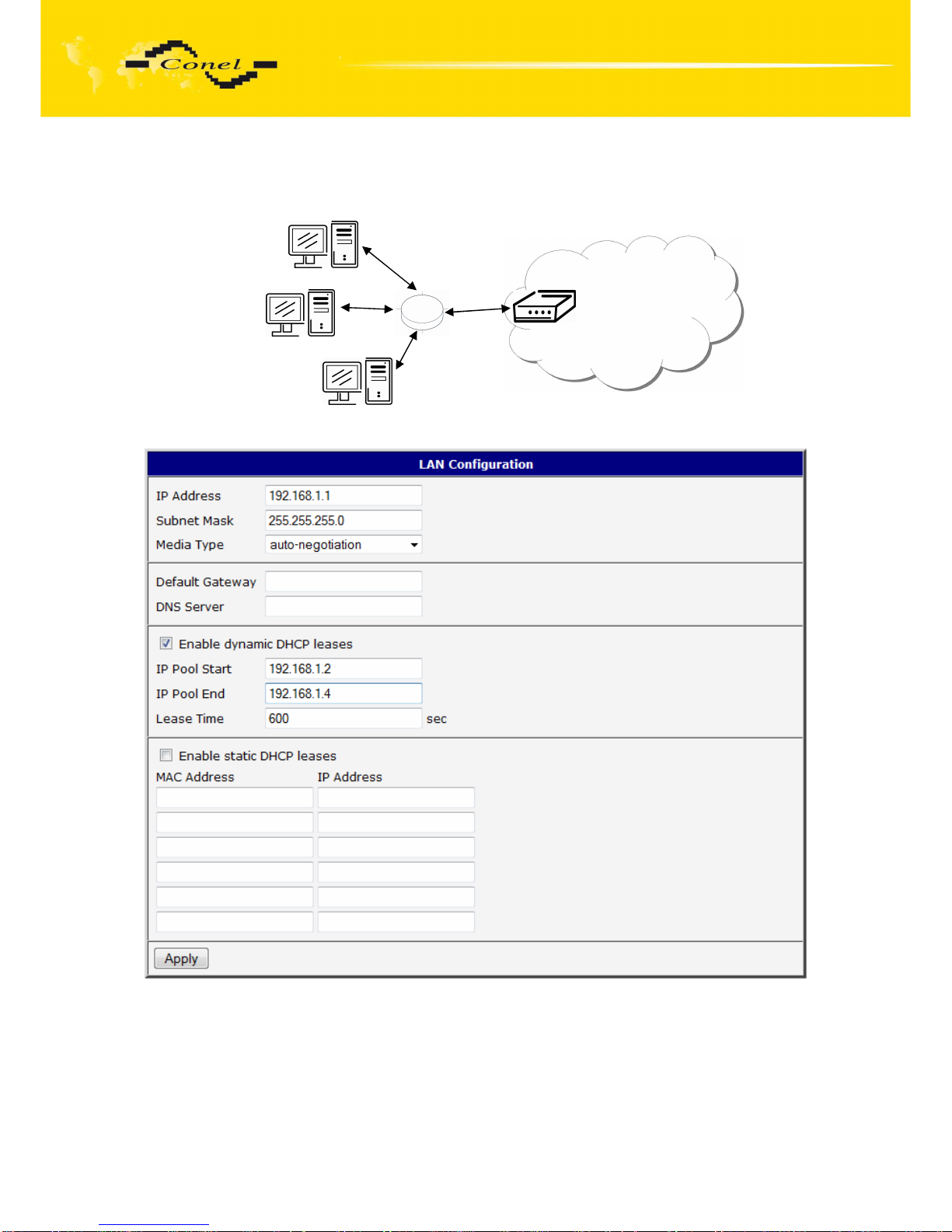
Example of the network interface with dynamic DHCP server:
192.168.1.3
192.168.1.4
ETH
192.168.1.2
GSM/GPRS
192.168.1.1
Page 43
CONFIGURATION
43
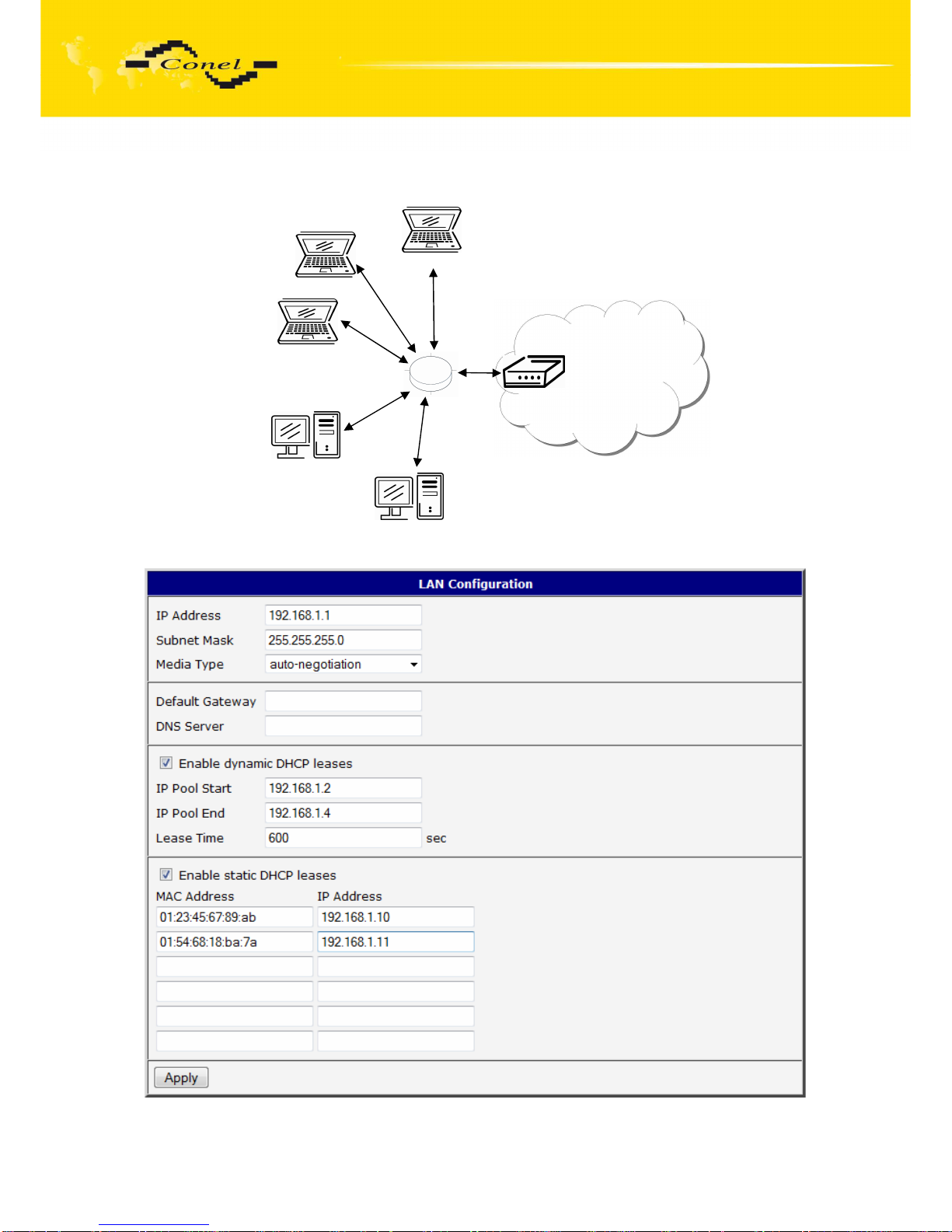
Example of the network interface with dynamic and static DHCP server:
192.168.1.3
192.168.1.4
ETH
192.168.1.2
GSM/GPRS
192.168.1.10
01-23-45-67-89-ab
192.168.1.11
01-54-68-18-ba-7e
192.168.1.1
Page 44
CONFIGURATION
44
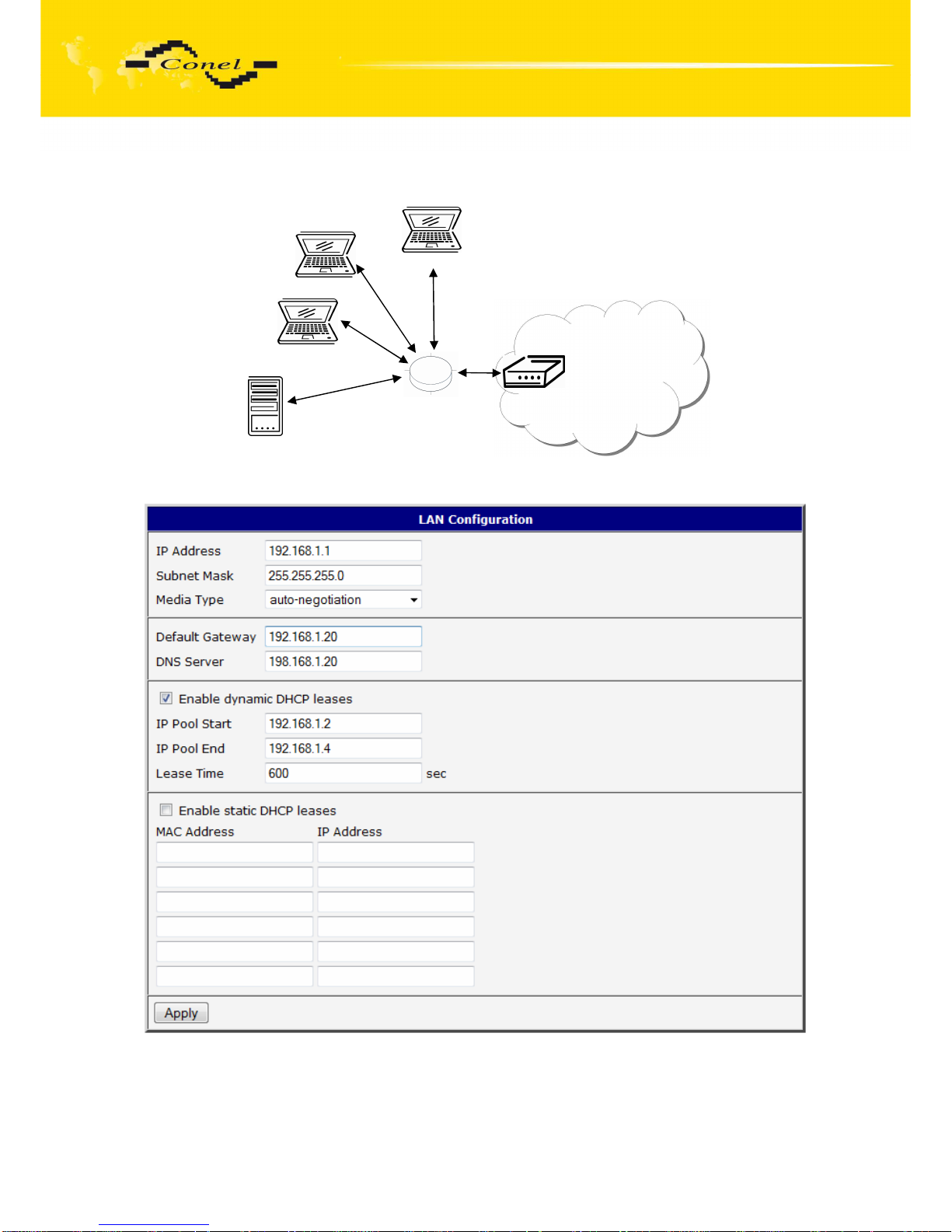
Example of the network interface with default gateway and DNS server:
192.168.1.3
192.168.1.4
192.168.1.1
ETH
192.168.1.2
GSM/GPRS
192.168.1.20
Page 45
CONFIGURATION
45
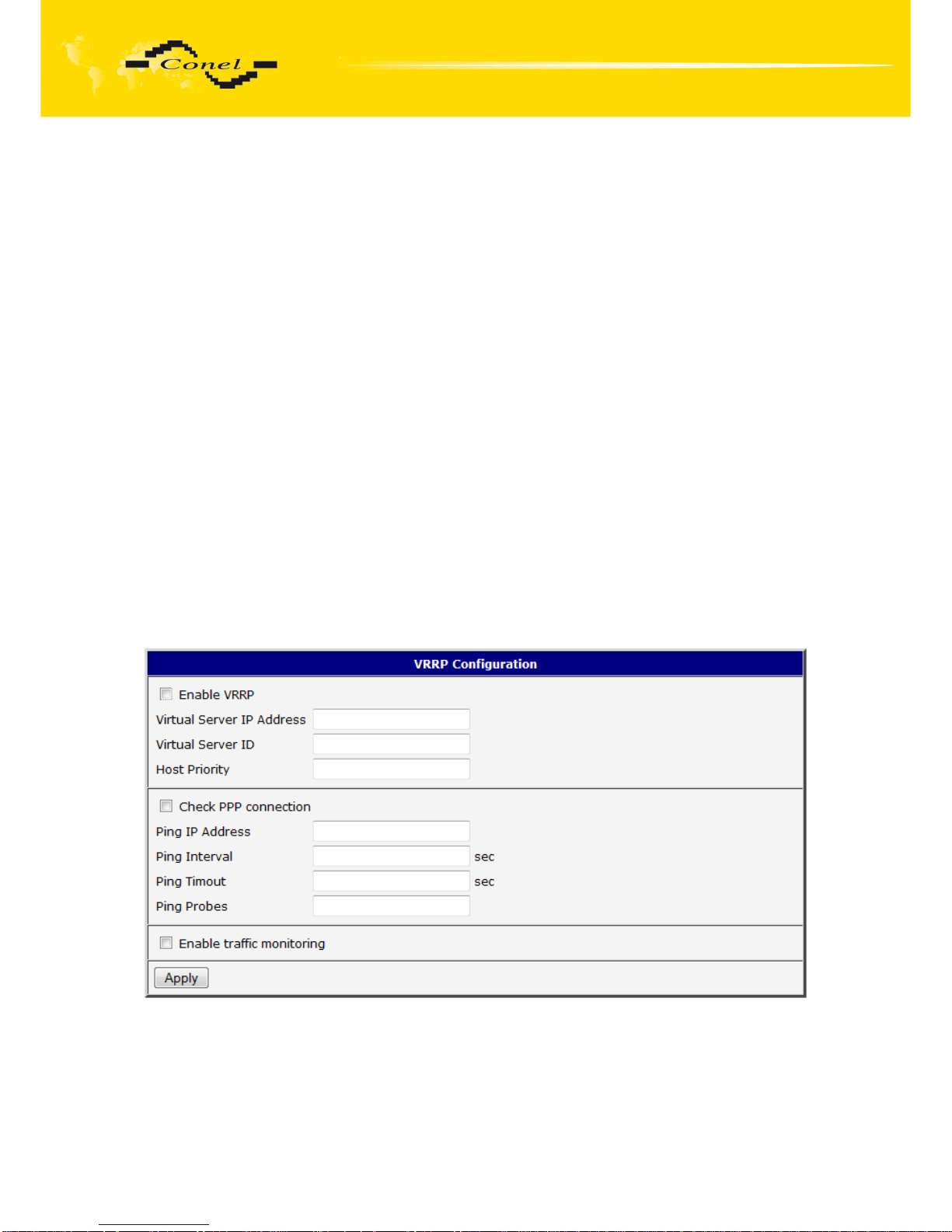
5.8. VRRP Configuration
To enter the VRRP configuration select the VRRP menu item. VRRP protocol (Virtual
Router Redundancy Protocol) is a technique, by which it is possible to forward routing from
main router to backup router in the case of the main router failure. If the Enable VRRP is
checked, then it is possible to set the following parameters. Parameter Virtual Server IP
Address sets virtual server IP address. This address should be the same for both routers. a
connected device sends its data via this virtual address. Parameter Virtual Server ID
distinguishes one virtual router on the network from others. This implies that the main and
backup routers must use the same value for this parameter. The router, with higher priority
set by the parameter Host Priority, is the main router. According to RFC 2338 the main router
has the highest possible priority - 255. The backup router has priority in range 1 – 254 (init
value is 100). The priority value equals 0 is not allowed.
It is possible to set Check PPP connection flag in the second part of the window.
The currently active router (either main or backup) will send testing messages to defined
Ping IP Address at periodic time intervals (Ping Interval) with setting time of waiting for
answer (Ping Timeout). The function check PPP connection is used as a supplement of
VRRP standard with the same final result. If there are no answers from remote devices (Ping
IP Address) for a defined number of probes (Ping Probes), then connection is switched to the
other line. It is possible to use for example a DNS server of mobile operator as a test
message (ping) IP address. There's an additional way for evaluating the state of the active
line. It is activated by selecting Enable traffic monitoring parameter. If this parameter is set
and any packet different from ping is sent to the monitored line, then any answer to this
packet is expected for Ping Timeout. If Ping Timeout expires with no answer received then
process of testing the active line continues the same way like in the case of standard testing
process after first test message answer drops out.
Page 46
CONFIGURATION
46
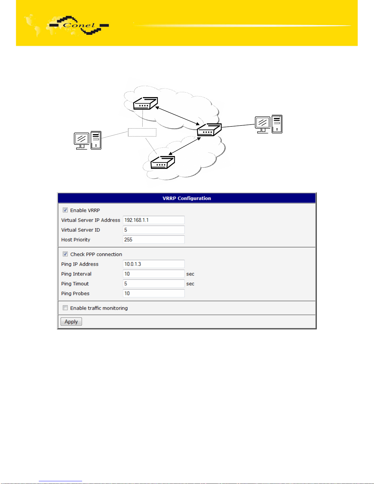
Example of the VRRP protocol:
Main router
Virtual server ID 5
Host priority 255
192.168.1.1
192.168.1.2
192.168.1.3
Backup router
Virtual server ID 5
Host priority 100
ETH
10.0.1.3
APN 1
APN 2
Page 47

CONFIGURATION
47
5.9. UMTS/GPRS Configuration
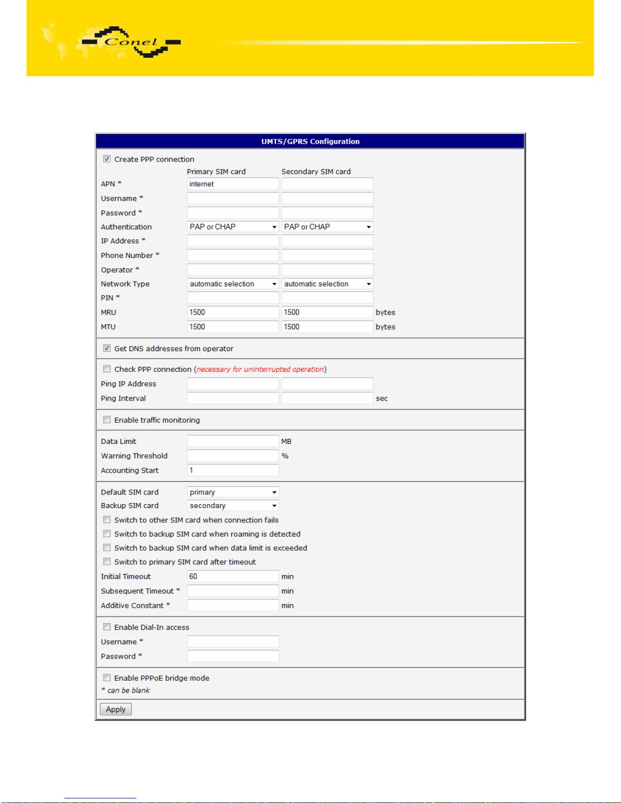
To enter the GPRS connection configuration select the GPRS menu item.
If the Create GPRS connection option is selected, the modem automatically tries to establish
GPRS connection after switching-on. In this window it is possible to define Username,
Password, authentificate protocol in the GSM network (Authentication), IP address
(IP Address) and phone number (Phone Number) for two different APN. If the IP address field
is not filled in, the operator automatically assigns the IP address when it is establishing the
connection. The router uses phone number *99***1# as default number. When it is set other
phone number, it will be use for establish GPRS or CSD connection.
If the APN field is not filled in, then the router automatically selects the APN by the
IMSI code of the SIM card. If the PLMN (operator number format) is not in the list of APN, then
default APN is “internet“. The mobile operator defines APN. The PLMN parameter is possible
to define in Operator item. If the PPPoE bridge mode is activated, then login is taken from the
connected client. Network Type item defines the way of data transmition, respectively
Automatic selection according to network availability or UMTS/HSDPA or GPRS/EDGE
technology. By parameter PIN it is possible to put PIN to the SIM card always during the
starting of the router.
Attention! If one SIM card is inserted into the router, which has two different APN’s,
the router cannot have the second SIM socket mounted. Otherwise it will switch to
secondary APN false. Also, correct PIN must be filled. For SIM cards with two APN’s
there will be the same PIN for both APN`s. Otherwise the SIM card can be blocked by
false SIM PIN.
The choice Get DNS address from operator is given for easier configuration on client
side. If this field is filled in, then the router tries to get an IP address of primary
and secondary DNS server from the operator automatically.
If the Check PPP connection option is selected, it has active control of connection
over PPP. The modem will automatically send the ping question to the selected domain
name or IP address (Ping IP Address) in periodic time intervals (Ping Interval). If the PING
failed, new ping be sent immediately. After three unsuccessfully pings on appropriate IP
address the router terminates connection and tries to establish a new connection. It is
possible to use, for example, the DNS server of a mobile operator as the ping IP address.
If the Enable Traffic Monitoring option is selected, then the router stops sending ping
questions to the Ping IP Address and it will watch traffic in PPP connection. If PPP
connection is without traffic longer than the Ping Interval, then the router sends ping
questions to the Ping IP Address.
Parameter Data limit set limit for data sending via GPRS. Parameter Warning
Threshold determine per cent of Data Limit in the range of 50% to 99%, which if is exceeded,
then the router sends an SMS in the form Router has exceeded (value of Warning
Threshold) of data limit. By the parameter Accounting Start it is possible to specify day
in month when it will start accounting defined in Data limit. If the parameter Switch to backup
SIM card when data limit is exceeded (see next) or Send SMS when datalimit is exceeded
(see SMS configuration) are not selected the data limit will not count.
At the bottom of configuration it is possible to set rules for switching between two
APN’s on the SIM card, in the event that one SIM card is inserted or between two SIM cards,
in the event that two SIM cards are inserted. Parameter Default SIM card sets default APN
or SIM card, from which it will try to establish the PPP connection. If this parameter is set
Page 48

CONFIGURATION
48
to none, the router launches in off-line mode and it is necessary to establish PPP connection
via SMS message.
If parameter Backup SIM card is set to none, then parameters Switch to other SIM
card when connection fails, Switch to backup SIM card when roaming is detected and Switch
to backup SIM card when data limit is exceeded switch the router to off-line mode.
If PPP connection fails, then the parameter Switch to other SIM card when connection
fails ensures switch to secondary SIM card or secondary APN of the SIM card. Failure of the
PPP connection can occur in two ways. When I start the router, when three fails to establish
a PPP connection. Or if it is checked Check the PPP connection, and is indicated by the loss
of a PPP connection.
In case that the roaming is detected the parameter Switch to backup SIM card
when roaming is detected enables switching to secondary SIM card or secondary APN
of the SIM card.
Parameter Switch to backup SIM card when data limit is exceeded enables switching
to secondary SIM card or secondary APN of the SIM card, when the data limit of default APN
is exceeded.
Parameter Switch to primary SIM card after timeout defines conditions, how to switch
back to the default SIM card or default APN.
Parameter Switch to backup SIM card when binary input is active enables switching
to secondary SIM card or secondary APN of the SIM card, when binary input ‘bin0’ is active.
Parameter Switch to primary SIM card after timeout enable defines the method, how
the router will try to switch back to default SIM card or default APN.
The following parameters define the time after which the router attempts to go back
to the default SIM card or APN. The first attempt to switch back to the primary SIM card or
APN shall be made for the time defined in the parameter Initial Timeout, range of this
parameter is from 1 to 10000 minutes. In an unsuccessful attempt to switch to default SIM
card, the router on the second attempt to try for the time defined in the parameter
Subsequent Timeout, range is from 1 to 10000 minutes. Any further attempt to switch back to
the primary SIM card or APN shall be made in time computed as the sum of the previous
time trial and time defined in the parameter Additive constants range is 1-10000 minutes.
Example: If parameter Switch to primary SIM card after timeout is checked and
parameters are set as follows Initial Timeout – 60min. Subsequent Timeout 30min
a Subsequent Timeout - 20min.The first attempt to switch the primary SIM card or APN shall
be carried out after 60 minutes. Switched to a failed second attempt made after 30 minutes.
Third after 50 minutes (30 +20). Fourth after 70 minutes (30 +20 +20).
Parameter Initial Timeout sets the time after which the Router tries to make connection
with default APN, range of this parameter is from 1 to 10000 minutes. Parameter Subsequent
Timeout sets the time period for every other next attempt to make connection with default
APN, range is from 1 to 10000 minutes. Parameter Additive Constant sets the amount of time
which is added to every attempt at main connection establishment after unsuccessful defined
attempt (for example: Additive Constant is 15 minutes. After a second unsuccessful attempt at
main connection establishment time of next attempt is extended by about 30 minutes etc.).
Range is from 1 to 1000 minutes.
In the bottom part of the window it is possible to define access over CSD connection
by Enable Dial-In Access function. Access can be secured by used the Username
and Password. When the router is in offline mode, the router is permanently available via
CSD connection.
Page 49

CONFIGURATION
49
In the last part of the window, is possible to switch on the PPPoE server by checking off
Enable PPPoE bridge mode. Then server waits for client from ethernet. After connection,
router sets the PPP connection over GPRS. Router then act as a transparent bridge between
PPPoE and PPP.
Attention! We recommend checking the GPRS connection in case of
uninterrupted running.
Annotation:
• MTU (Maximum Transmission Unit) – it is the identifier of the maximum size
of packet, which is possible to transfer in a given environment.
• MRU (Maximum Receiving Unit) – it is the identifier of the maximum size
of packet, which is possible to receive in a given environment.
Default value is 1500 bytes. Other settings may cause incorrect transmission of data.
Page 50
CONFIGURATION
50
The changes in settings will apply after pressing the Apply button.
Page 51
CONFIGURATION
51
5.10. Firewall Configuration
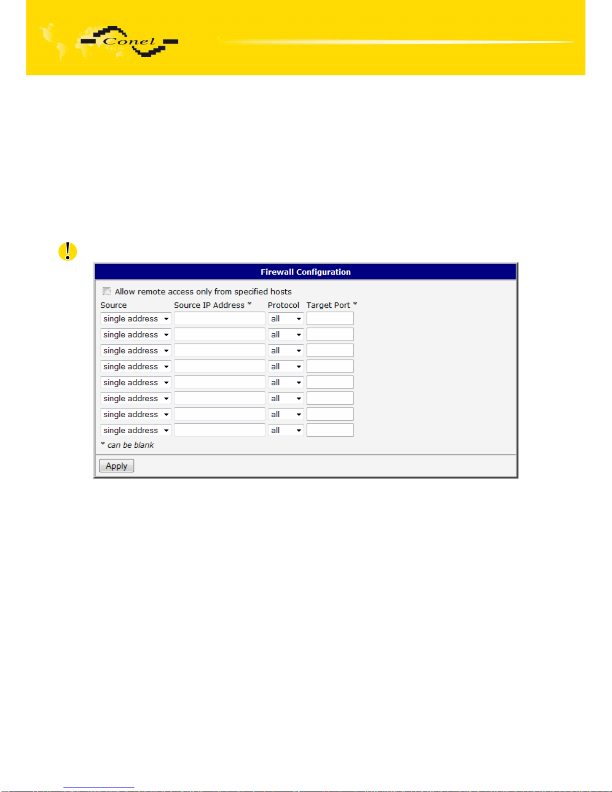
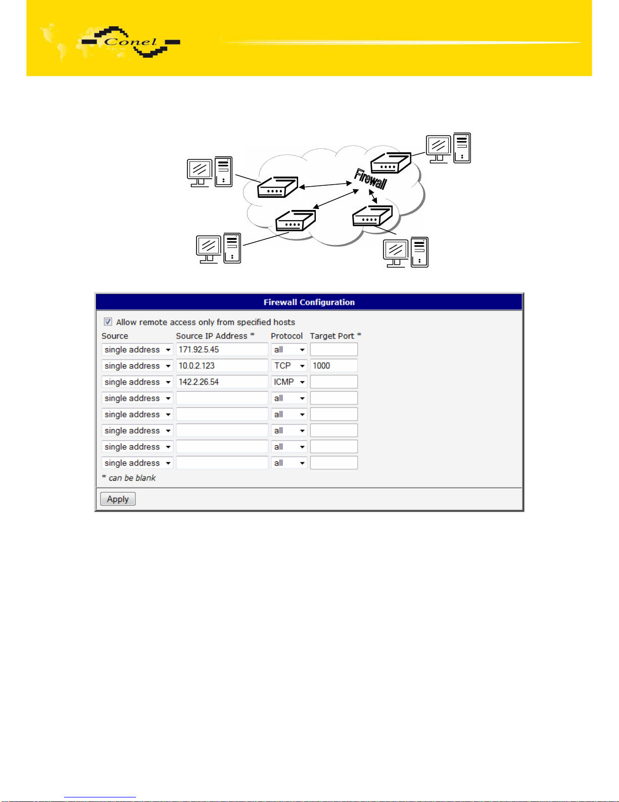
By the help of a firewall it is possible to set IP addresses from which are possible to
remotely access the router. The choice Allow remote access only from specified hosts is
given for easier configuration of hosts. In this firewall configuration it is possible to set up to
four remote accesses by the help of Source, Source IP Address, Protocol and Target Port.
Parameter Source defines if access is allowed to one IP address which is defined by
Source IP Address, or every IP addresses. In menu Protocol it is possible to specify protocol
for remote access, it is possible to allow all protocols (all), or only one protocol UDP, TCP
or ICMP. By parameter Target Port it is possible to specify a port number.
The changes in settings will apply after pressing the Apply button.
Caution! Firewall doesn’t filter via Ethernet.
Page 52
CONFIGURATION
52
Example of the firewall configuration:
10.0.2.123
171.92.5.45
142.2.26.54
TCP/1000
ICMP
ALL
Page 53
CONFIGURATION
53
5.11. NAT Configuration
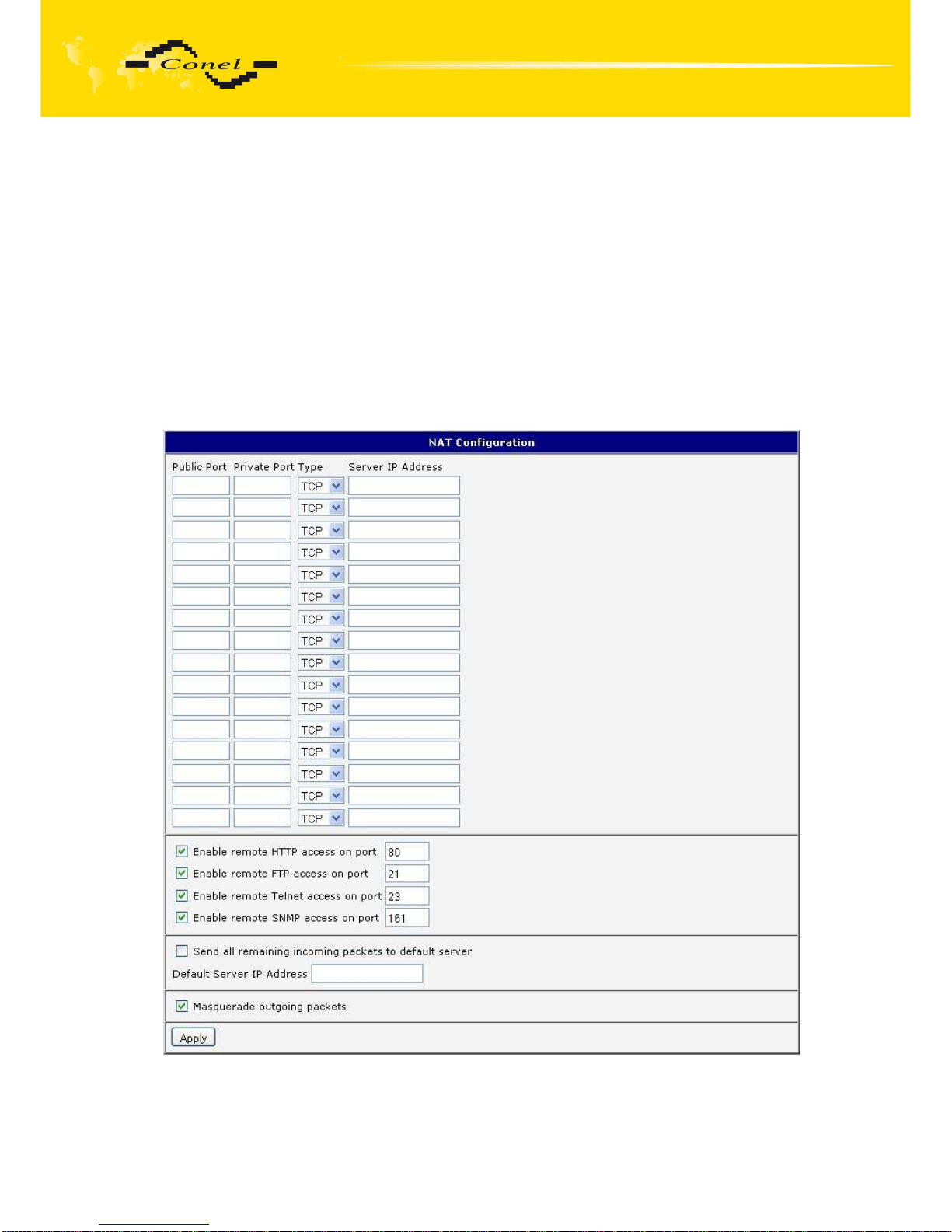
To enter the Network Address Translation configuration, select the NAT menu item.
By checking off the Send all incoming packets to default server item and setting
the Default Server item it is possible to put the router into the mode in which all incoming data
from GPRS will be routed to the computer with the defined IP address.
If the Enable remote HTTP access field and port number is filled in, then configuration
of the router over web interface is possible. Choice Enable remote FTP access on port and
port number makes it possible to access over FTP. Choice Enable remote Telnet access and
port number makes it possible to access over Telnet. Choice Enable remote SNMP access
and port number makes it possible to access to SNMP agent. Choice Masquerade outgoing
packets option turns the system address translation NAT.
The changes in settings will apply after pressing the Apply button.
Page 54
CONFIGURATION
54
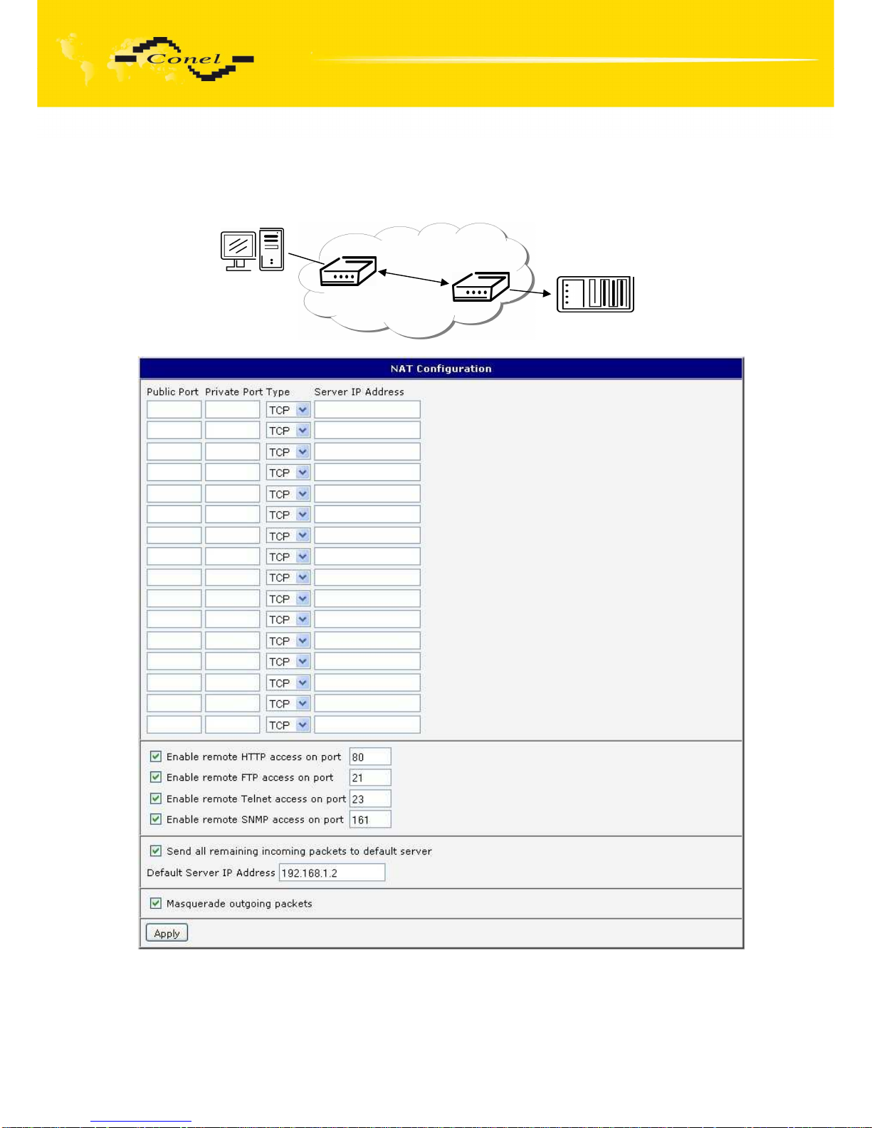
Example of the configuration with one connection equipment on the router:
In these configurations it is important to have marked choice of Send all remaining
incoming packets it default server, IP address in this case is the address of the device behind
the router. Connected equipment behind the router must have set Default Gateway on the
router. Connected device replies, while PING on IP address of SIM card.
162.209.13.222
192.168.1.2
ppp0 10.0.0.1
Page 55
CONFIGURATION
55
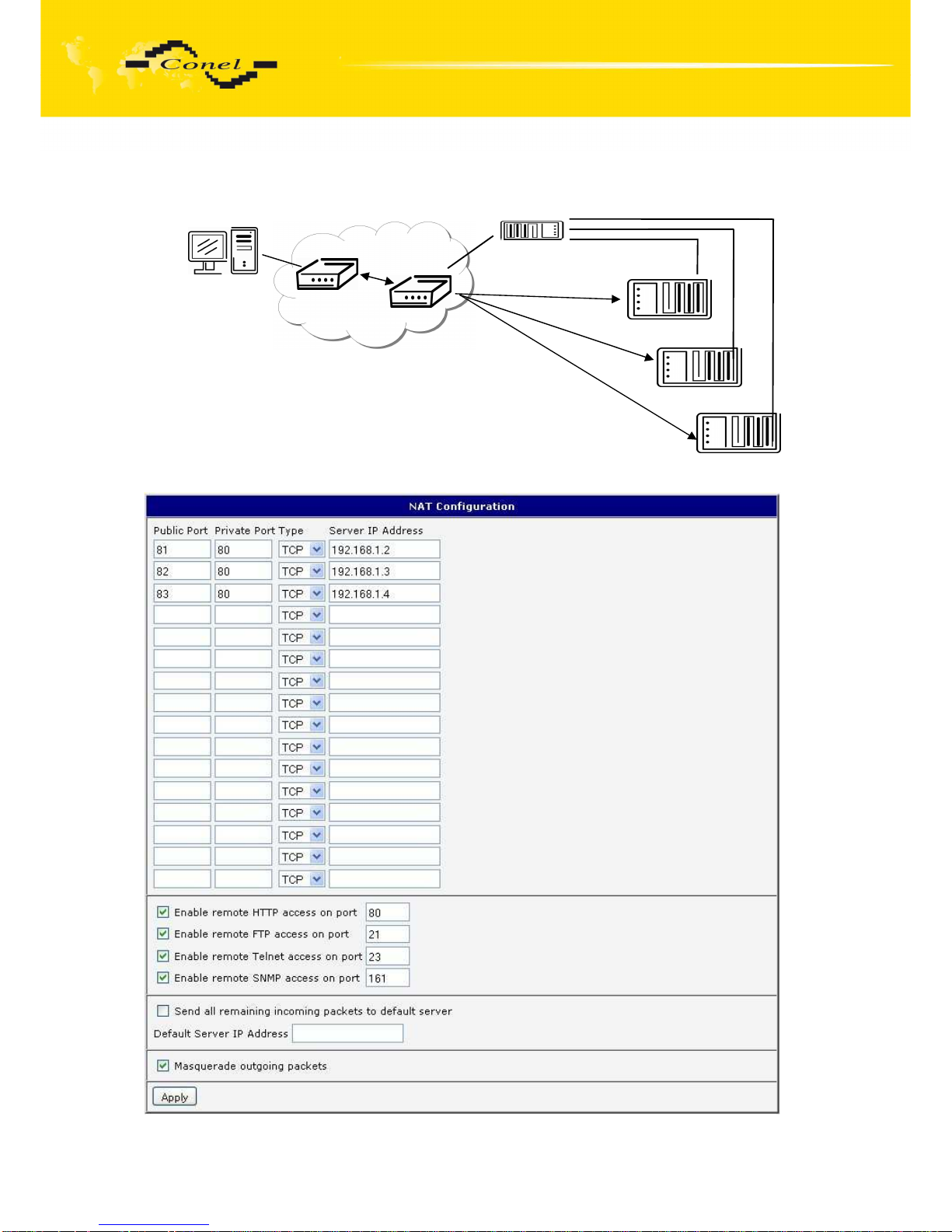
Example of the configuration with more connected equipment:
162.209.13.222
192.168.1.2:80
192.168.1.3:80
192.168.1.4:80
ppp0 10.0.0.1
SWITCH
10.0.0.1:81
10.0.0.1:82
10.0.0.1:83
Page 56
CONFIGURATION
56
In this configuration equipment wired behind the router defines the address Server IP
Address. The router replies, while PING on address of SIM card. Access on web interface of
the equipment behind the router is possible by the help of Port Forwarding, when behind IP
address of SIM is indicating public port of equipment on which we want to come up. At
demand on port 80 it is surveyed singles outer ports (Public port), there this port isn't defined,
therefore at check selection Enable remote http access it automatically opens the web
interface router. If this choice isn't selected and is selected volition Send all remaining
incoming packets to the default server fulfill oneself connection on induction IP address. If it
is not selected election Send all remaining incoming packets to default server and Default
server IP address then connection requests a failure. If it is necessary to set more than 8
rules for NAT, then it is possible to insert into start up script following script.
If necessary set more than twelve rules for NAT, then is possible insert into start up
script following script:
iptables -t nat -A napt -p tcp --dport [PORT_PUBLIC] -j DNAT --to-destination
[IPADDR]:[PORT1_PRIVATE]
Concrete IP address [IPADDR] and ports numbers [PORT_PUBLIC]
and [PORT1_PRIVATE] are filled up into square bracket.
5.12. OpenVPN Tunnel Configuration
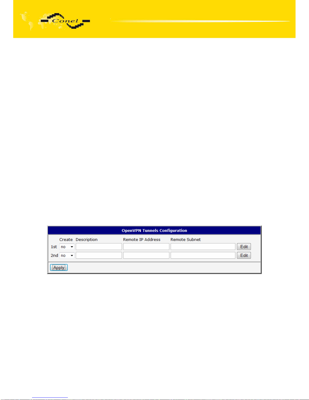
OpenVPN tunnel configuration can be called up by option OpenVPN item in the
menu. OpenVPN tunnel allows protected connection of two networks LAN to the one which
looks like one homogenous. In the OpenVPN Tunnels Configuration window are two rows,
each row for one configured OpenVPN tunnel. The column Create switches on tunnels, other
columns contain values view set in the OpenVPN Tunnel Configuration windows;
configuration is possible by the Edit button.
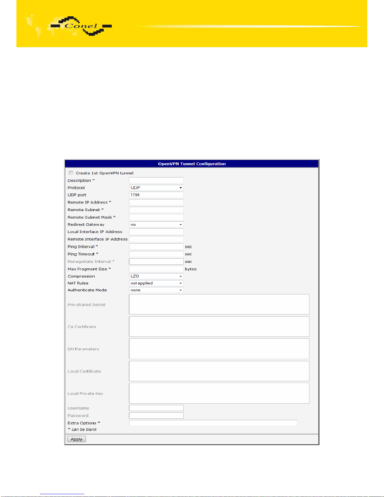
In the window can be defined tunnel name (Description) and Protocol, by which the
tunnel will communicate. At choice is UDP, TCP server or TCP client protocol which has to
have defined port protocol (UDP port nebo TCP port). On off - side tunnel IP address
(Remote External IP Address), address nets behind off - side tunnel (Remote Subnet), mask
nets behind off - side tunnel (Remote Subnet Mask). By parameter Redirect Gateway is
possible to redirect all traffic on Ethernet. Parameter Local Interface IP Address defines local
interface IP address, parameter Remote Interface IP Address defines the interface IP
address of the off-side tunnel. Parameter Ping Interval defines the time period after which it
sends a message to off-side and by parameter Ping Timeout waits on message from off-side
tunnel. For OpenVPN tunnel right verify parameter Ping Timeout has to be bigger than Ping
Interval. Parameter Renegotiate Interval sets renegotiate period (reauthorization) of the
OpenVPN tunnel. This parameter is possible to set only at username/password
authentication or at X.509 certificate using. By parameter Max Fragment Size it is possible to
define maximum sending packet size. Sending data is possible compress by lossless LZO
Page 57
CONFIGURATION
57
compressions by parameter Compression, compression has to be on both tunnel ends.
By parameter NAT Rules it is possible to apply set NAT rules to OpenVPN tunnel. By
Authenticate Mode it is possible to choose authentication. On choice are none
authentication, or by Pre-shared secret which set shared key for both off-side tunnel; or by
Username/Password which enable authentication by CA Certificate, Username and
Password; next can be X.509 Certificate (client), this enables authentication by CA
Certificate, Local Certificate and Local Private Key; last possibility is X.509 Certificate
(server) which enables authentication by CA Certificate, DH Parameters, Local Certificate
and Local Private Key. By the help of parameter Extra Options it is possible to define
additional parameters of the OpenVPN tunnel, for example DHCP options etc.
The changes in settings will apply after pressing the Apply button.
Page 58
CONFIGURATION
58
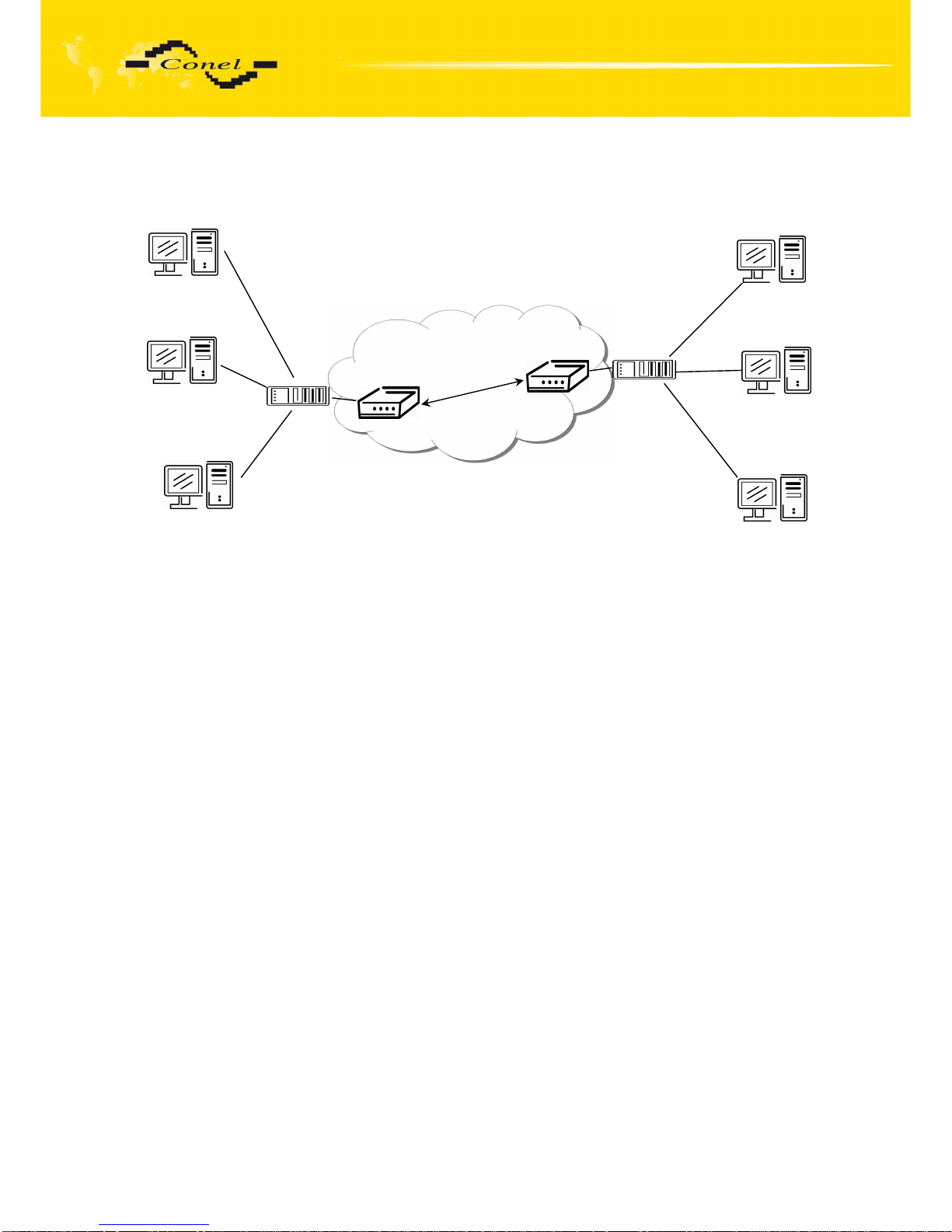
Example of the OpenVPN tunnel configuration:
OpenVPN tunnel configuration:
A B
Protocol UDP UDP
UDP Port 1194 1194
Remote IP Address: 10.0.0.2 10.0.0.1
Remote Subnet: 192.168.2.0 192.168.1.0
Remote Subnet Mask: 255.255.255.0 255.255.255.0
Local Interface IP Address: 19.16.1.0 19.16.2.0
Remote Interface IP Address: 19.16.2.0 19.18.1.0
Compression LZO LZO
Authenticate mode: none none
192.168.1.4
192.168.1.3
192.168.1.2
192.168.2.2
192.168.2.3
192.168.2.4
ppp0 10.0.0.1
192.168.1.0
tun0 19.16.1.0
ppp0 10.0.0.2
192.168.2.0
tun 0 19.16.2.0
OpenVPN tunnel
Default Gateway 192.168.1.1
Default Gateway 192.168.2.1
A
B
Page 59
CONFIGURATION
59
5.13. IPSec Tunnel Configuration
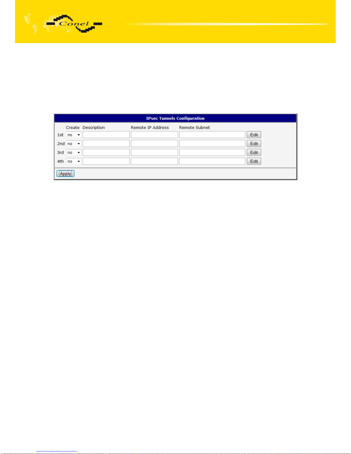
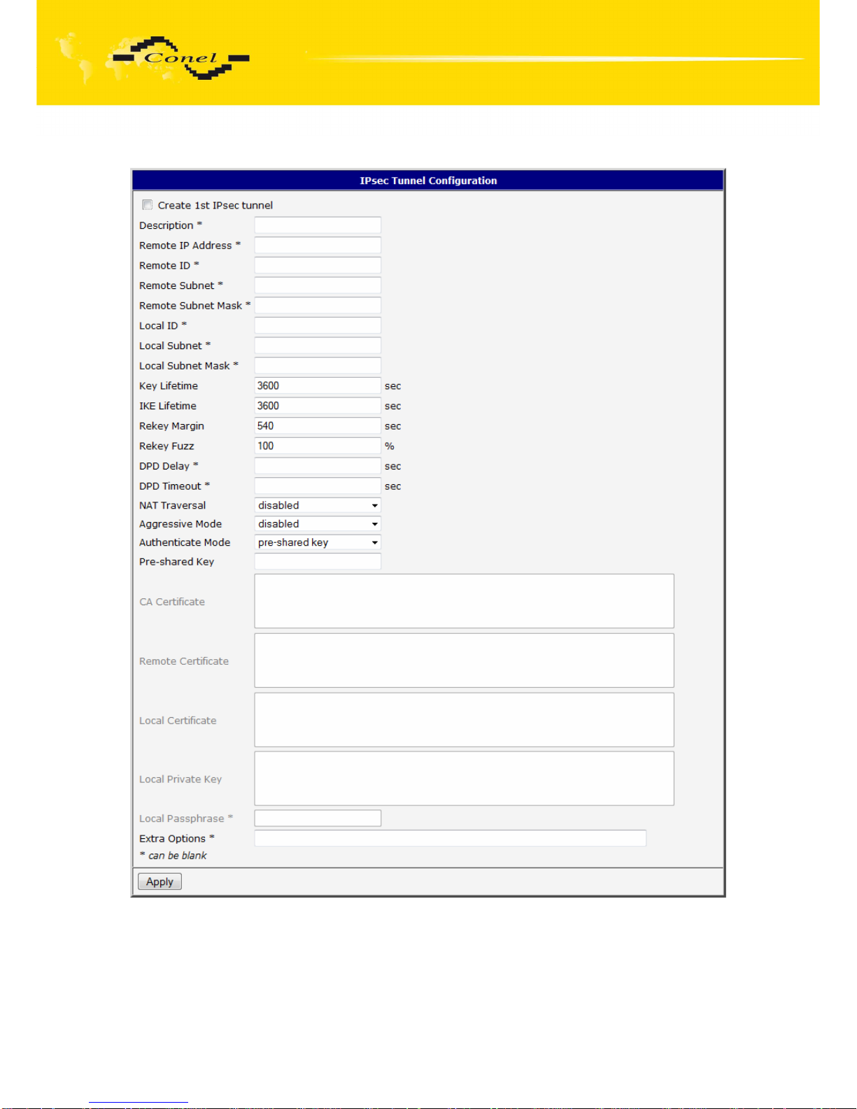
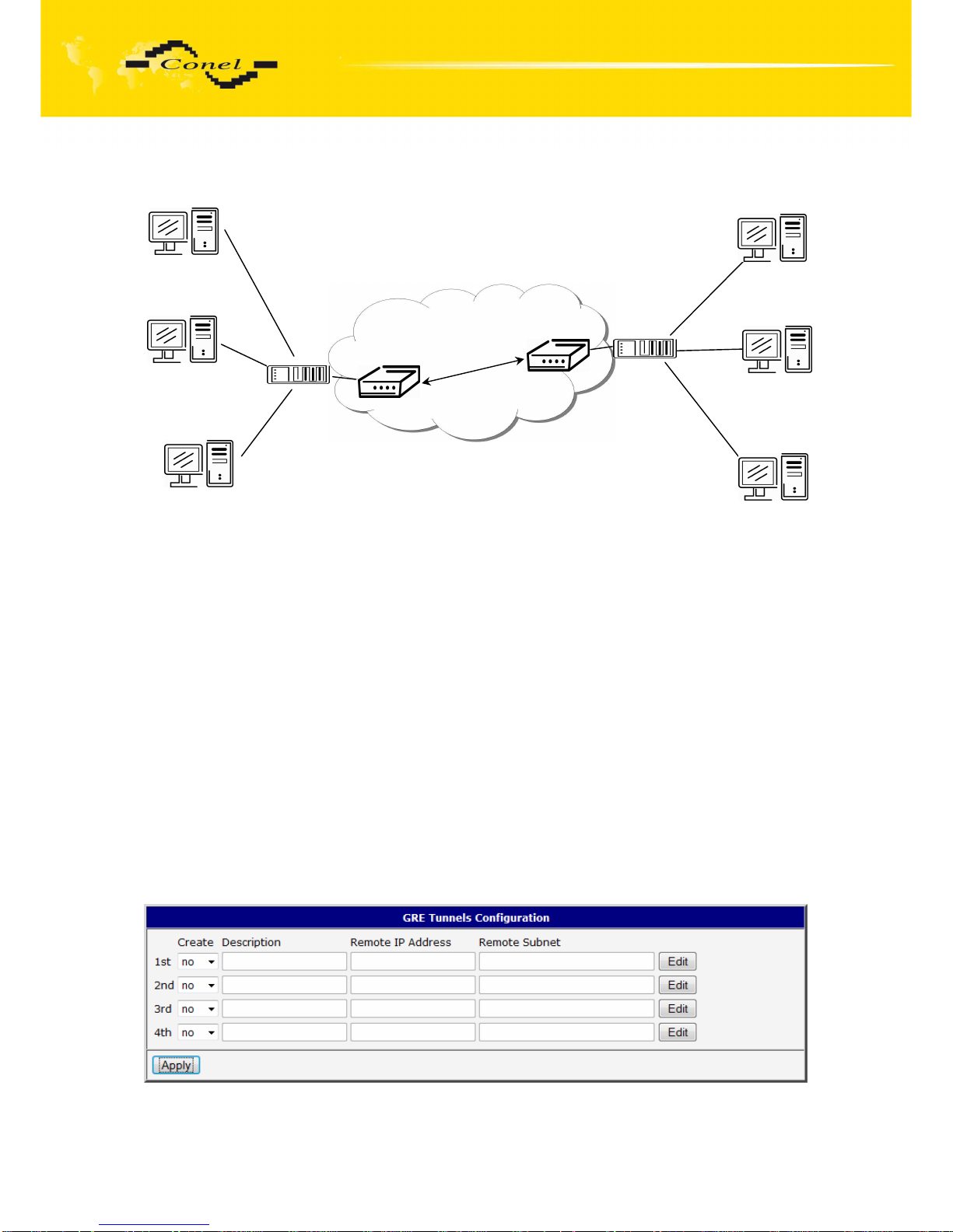
IPsec tunnel configuration can be called up by option IPsec item in the menu. IPsec
tunnel allows protected connection of two networks LAN to the one which looks like one
homogenous. In the IPsec Tunnels Configuration window are four rows, each row for one
configured IPSec tunnel. The column Create switches on tunnels, other columns contain
values view set in the IPsec Tunnel Configuration windows; configuration is possible by
the Edit button.
In the IPsec Tunnel Configuration windows it is possible to define the tunnel name
(Description), off - side tunnel IP address or domain name (Remote IP Address),
identification of off-side tunnel (Remote ID), address nets behind off - side tunnel (Remote
Subnet), mask nets behind off - side tunnel (Remote Subnet Mask), identification of local
side (Local ID), local subnet address (Local Subnet), local network mask (Local Subnet
Mask), sharable key for both parties tunnel (Pre shared Key), service life keys (Key Lifetime)
and service life IKA SA (IKE Lifetime). Rekey Margin specifies how long before connection
expiry should attempt to negotiate a replacement begin. Rekey Fuzz specifies the maximum
percentage by which Rekey Margin should be randomly increased to randomize re-keying
intervals. Parameter DPD Delay defines time after which is made IPsec tunnel verification.
By parameter DPD Timeout is set timeout of the answer. If address translation between two
end points of the IPsec tunnel is used, it needs to allow NAT Traversal (Enabled). If
parameter Aggressive mode is enabled, then establishing of IPsec tunnel will be faster, but
encryption will set permanently on 3DES-MD5. Authentication is possible to set by parameter
Authenticate mode, at choice are following possibilities: Pre-shared key or X.509 Certificate.
Parameter Pre-shared Key set shared key for both off-side tunnel. At authentication by X.509
certificate it is necessary put in certificates CA Certificate, Remote Certificate and Local
Certificate and private key Local Private Key and Local Passphrase. The certificates and
private keys have to be in PEM format. As certificate it is possible to use only certificate
which has start and stop tag certificate. Parameters ID contain two parts: hostname and
domain-name. Items which can be blank, are used for to exact IPsec tunnel identification. By
the help of parameter Extra Options it is possible to define additional parameters of the IPsec
tunnel, for example secure parameters etc.
The changes in settings will apply after pressing the Apply button.
Page 60
CONFIGURATION
60
Page 61
CONFIGURATION
61
Example of the IPSec Tunnel configuration:
IPsec tunnel configuration:
A B
Remote IP Address: 10.0.0.2 10.0.0.1
Remote Subnet: 192.168.2.0 192.168.1.0
Remote Subnet Mask: 255.255.255.0 255.255.255.0
Local Subnet: 192.168.1.0 192.168.2.0
Local Subnet Mask: 255.255.255.0 255.255.255.0
Authenticate mode: pre-shared key pre-shared key
Pre-shared key test test
5.14. GRE Tunnels Configuration
To enter the GRE tunnels configuration, select the GRE menu item. It is possible to
configure up to four GRE tunnels. In the GRE Tunnels Configuration window are four rows,
each row for one configured GRE tunnel. The column Create switches on tunnels, other
columns contain values view set in the GRE Tunnel Configuration windows; configuration is
possible by Edit button.
192.168.1.4
192.168.1.3
192.168.1.2
192.168.2.2
192.168.2.3
192.168.2.4
ppp0 10.0.0.1
192.168.1.0
ppp0 10.0.0.2
192.168.2.0
IPSec tunel
Default Gateway 192.168.1.1
Default Gateway 192.168.2.1
A
B
Page 62
CONFIGURATION
62
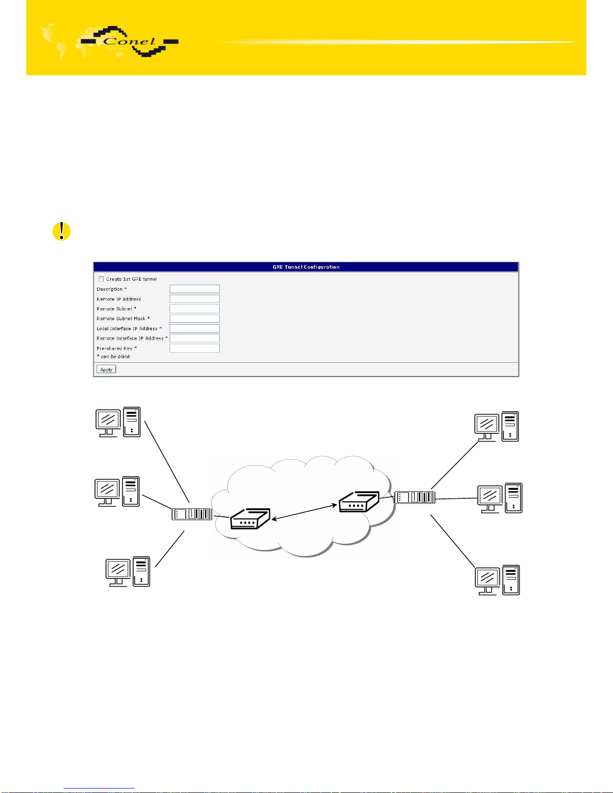
The tunnels are active after selecting Create x GRE tunnel. In the singles window it
is possible to define the IP address of the remote side of the tunnel (Remote External IP
Address), internal IP address of the local side of the tunnel (Local Internal IP Address),
internal IP address of the remote side of the tunnel (Remote Internal IP Address), address
of the network behind the remote side of the tunnel (Remote Subnet) and the mask of the
network behind the remote side of the tunnel (Remote Subnet Mask). The GRE tunnel is
used for connection of two networks to one that appears as one homogenous. Last item
(“Pre-shared Key”) defines 32b number that identifies shared key of tunnel. This code must
be on both sides of same.
Attention, GRE tunnel doesn’t connect itself via NAT.
The changes in settings will apply after pressing the Apply button.
Example of the GRE Tunnel configuration:
GRE tunnel Configuration:
A B
Remote External IP Address: 10.0.0.2 10.0.0.1
Remote Subnet: 192.168.2.0 192.168.1.0
Remote Subnet Mask: 255.255.255.0 255.255.255.0
192.168.1.4
192.168.1.3
192.168.1.2
192.168.2.2
192.168.2.3
192.168.2.4
ppp0 10.0.0.1
ppp0 10.0.0.2
GRE tunel
Default Gateway 192.168.1.1
Default Gateway 192.168.2.1
A
B
192.168.1.1
192.168.2.1
Page 63
CONFIGURATION
63
5.15. L2TP Configuration
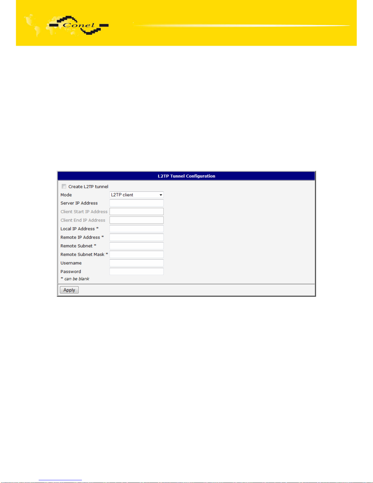
To enter the L2TP tunnels configuration, select the L2TP menu item. L2TP tunnel
allows protected connection by password of two networks LAN to the one which it looks like
one homogenous. The tunnels are active after selecting Create L2TP tunnel.
In the window it is possible to define L2TP tunnel mode (Mode) on the router side,
in case of client IP address of server (Server IP Address), start IP address in range, which is
offered by server to clients (Client Start IP Address), end IP address in range, which is
offered by server to clients (Client End IP Address), IP address of the local side of the tunnel
(Local IP Address), IP address of the remote side of the tunnel (Remote IP Address),
address of the network behind the remote side of the tunnel (Remote Subnet), the mask
of the network behind the remote side of the tunnel (Remote Subnet Mask), username for
login to L2TP tunnel (Username) and password (Password).
The changes in settings will apply after pressing the Apply button.
Page 64
CONFIGURATION
64
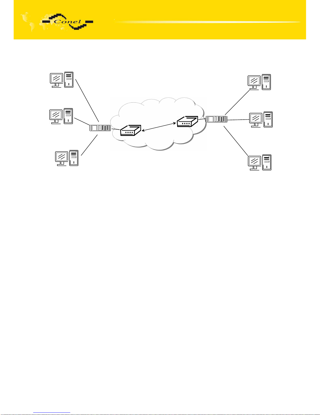
Example of the L2TP Tunnel configuration:
Configuration of the L2TP tunnel:
A B
Mode L2TP Server L2TP Client
Server IP Address --- 10.0.0.1
Client Start IP Address: 192.168.3.2 ---
Client End IP Address: 192.168.3.254 ---
Local IP Address: 192.168.3.1 ---
Remote IP Address --- ---
Remote Subnet 192.168.2.0 192.168.1.0
Remote Subnet Mask 255.255.255.0 255.255.255.0
Username username username
Password password password
192.168.1.4
192.168.1.3
192.168.1.2
192.168.2.2
192.168.2.3
192.168.2.4
ppp0 10.0.0.1
192.168.1.1
ppp0 10.0.0.2
192.168.2.1
L2TP tunel
Default Gateway 192.168.1.1
Default Gateway 192.168.2.1
A
B
Page 65
CONFIGURATION
65
5.16. DynDNS Client Configuration
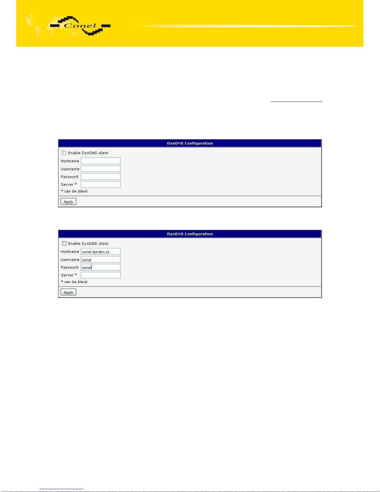
DynDNS client Configuration can be called up by option DynDNS item in the menu. In
the window can be defined a third order domain registered on server
www.dyndns.org
(Hostname), user name (Username) and password (Password). If you want to use a different
server than www.dyndns.org, fill in his address to the item server (Server). If this item is left
blank, the default server is used.
The changes in settings will apply after pressing the Apply button.
Example of the DynDNS client configuration with domain conel.dyndns.org, username
conel, password conel and default server http://members.dyndns.org:
If DNS servers are not assigned by the operator, then it is possible to configure it by
inserting of script into start up window:
echo “nameserver xxx.xxx.xxx.xxx“ > /etc/resolf.conf, where xxx.xxx.xxx.xxx is
IP address of the first DNS server,
echo “nameserver yvy.yyy.yyy.yyy“ >> /etc/resolf.conf, where yvy.yyy.yyy.yyy is
IP address of the second DNS server.
Page 66
CONFIGURATION
66
5.17. NTP Client Configuration
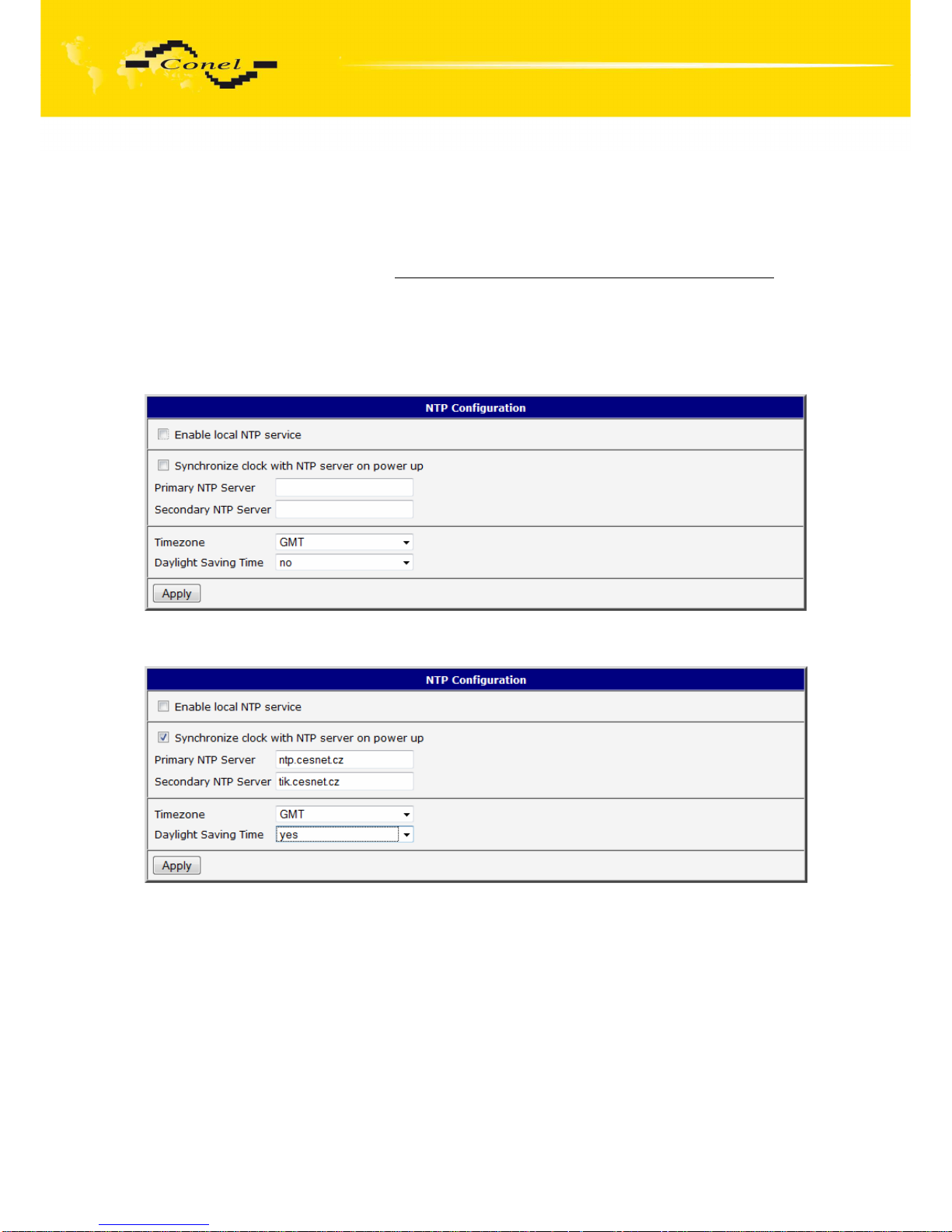
NTP client Configuration can be called up by option NTP item in the menu. In the
window can be defined the address prime (Primary NTP server Address) and secondary
NTP server (Secondary NTP server Address), by the help of which the router, after first
interface to the GPRS from make power supply, will adjust the inner clock. Example of NTP
server address can be seenon ntp.isc.org/bin/view/Servers/StratumOneTimeServers. By
parameter Timezone it is possible to set the time zone of the router. By parameter Daylight
Saving Time is possible to define time shift.
By parameter Enable local NTP service it is possible to set the router in mode, that it
can serve as NTP server for other devices.
The changes in settings will apply after pressing the Apply button.
Example of the NTP configuration with set primary and secondary NTP server
and with daylight saving time:
5.18. SNMP Configuration
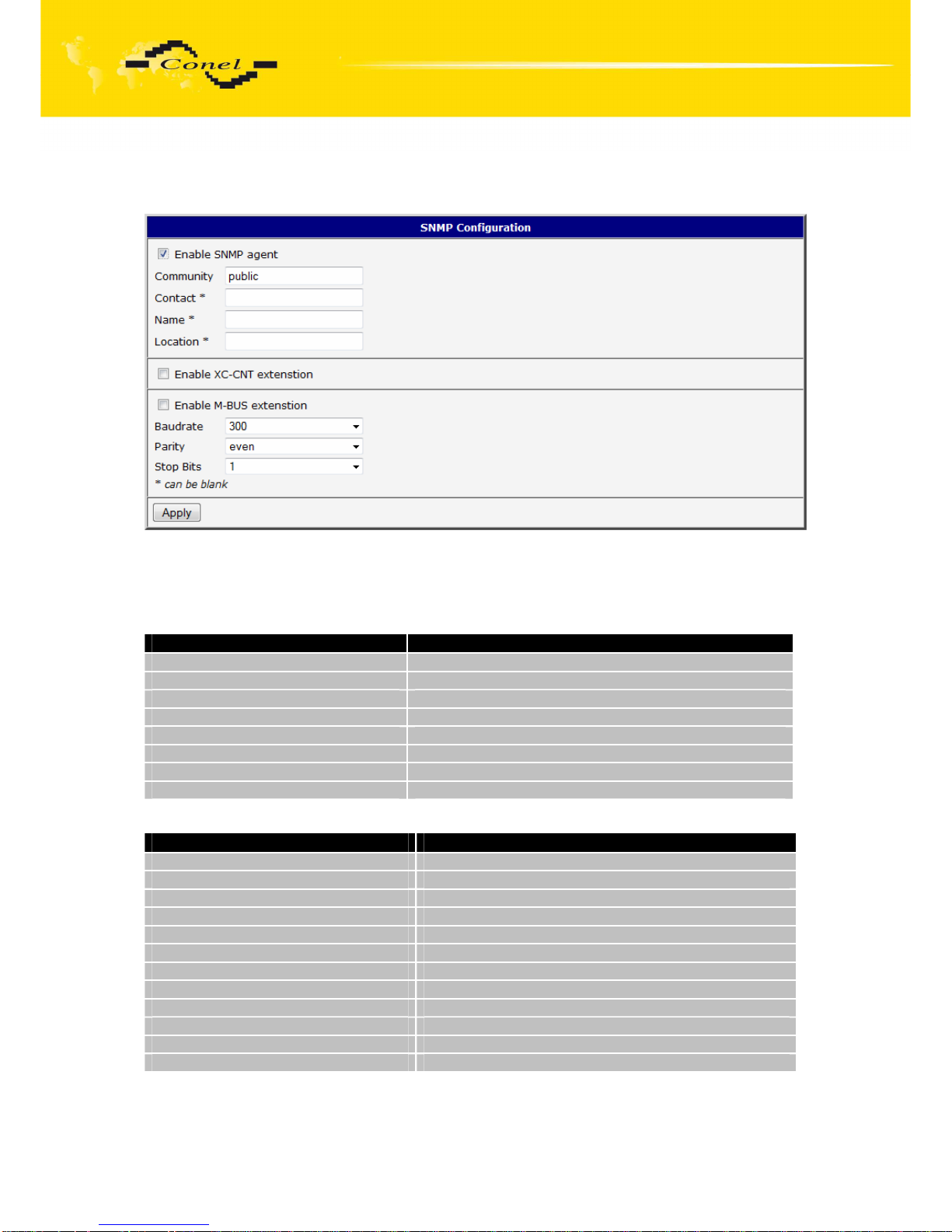
To enter the SNMP Configuration it is possible with SNMP agent ver.1 configuration
which sends information about the router, eventually about the status of the expansion port
CNT or M-BUSD.
The Community item defines the password for access to the SNMP agent. Item
Contact identifies a person who manages the router together with information how to contact
this person, item Name is the designation of the router and item Location describes the
physical placing of the router.
By choosing Enable XC-CNT extension it is possible to monitor the expansion port
CNT inputs status or by choosing Enable M-BUS extension and enter the Baudrate, Parity
Page 67
CONFIGURATION
67
and Stop Bits it is possible to monitor the meter status connected to the expansion port
M-BUSD status.
Every monitor value is uniquely identified by the help of number identifier OID - Object
Identifier. OID is finished by „.9“.
For the expansion port CNT the following range of OID is used:
OID Description
.1.3.6.1.4.1.30140.2.1.1.0 Analogy input AN1 (range 0-4095)
.1.3.6.1.4.1.30140.2.1.2.0 Analogy input AN2 (range 0-4095)
.1.3.6.1.4.1.30140.2.1.3.0 Counter input CNT1 (range 0-4294967295)
.1.3.6.1.4.1.30140.2.1.4.0 Counter input CNT2 (range 0-4294967295)
.1.3.6.1.4.1.30140.2.1.5.0 Binary input BIN1 (values 0,1)
.1.3.6.1.4.1.30140.2.1.6.0 Binary input BIN2 (values 0,1)
.1.3.6.1.4.1.30140.2.1.7.0 Binary input BIN3 (values 0,1)
.1.3.6.1.4.1.30140.2.1.8.0 Binary input BIN4 (values 0,1)
For the expansion port M-BUSD the following range of OID is used:
OID Description
.1.3.6.1.4.1.30140.2.2.<address>.1.0 IdNumber – meter number
.1.3.6.1.4.1.30140.2.2.<address>.2.0 Manufacturer
.1.3.6.1.4.1.30140.2.2.<address>.3.0 Version – specified meter version
.1.3.6.1.4.1.30140.2.2.<address>.4.0 Medium – type of metered medium
.1.3.6.1.4.1.30140.2.2.<address>.5.0 Status – errors report
.1.3.6.1.4.1.30140.2.2.<address>.6.0 0. VIF – value information field
.1.3.6.1.4.1.30140.2.2.<address>.7.0 0. measured value
.1.3.6.1.4.1.30140.2.2.<address>.8.0 1. VIF – value information field
.1.3.6.1.4.1.30140.2.2.<address>.9.0 1. measured value
…
.1.3.6.1.4.1.30140.2.2.<address>.100.0 47. VIF – value information field
.1.3.6.1.4.1.30140.2.2.<address>.101.0 47. measured value
The meter address can be from range 0..254 when 254 is broadcast.
Page 68
CONFIGURATION
68
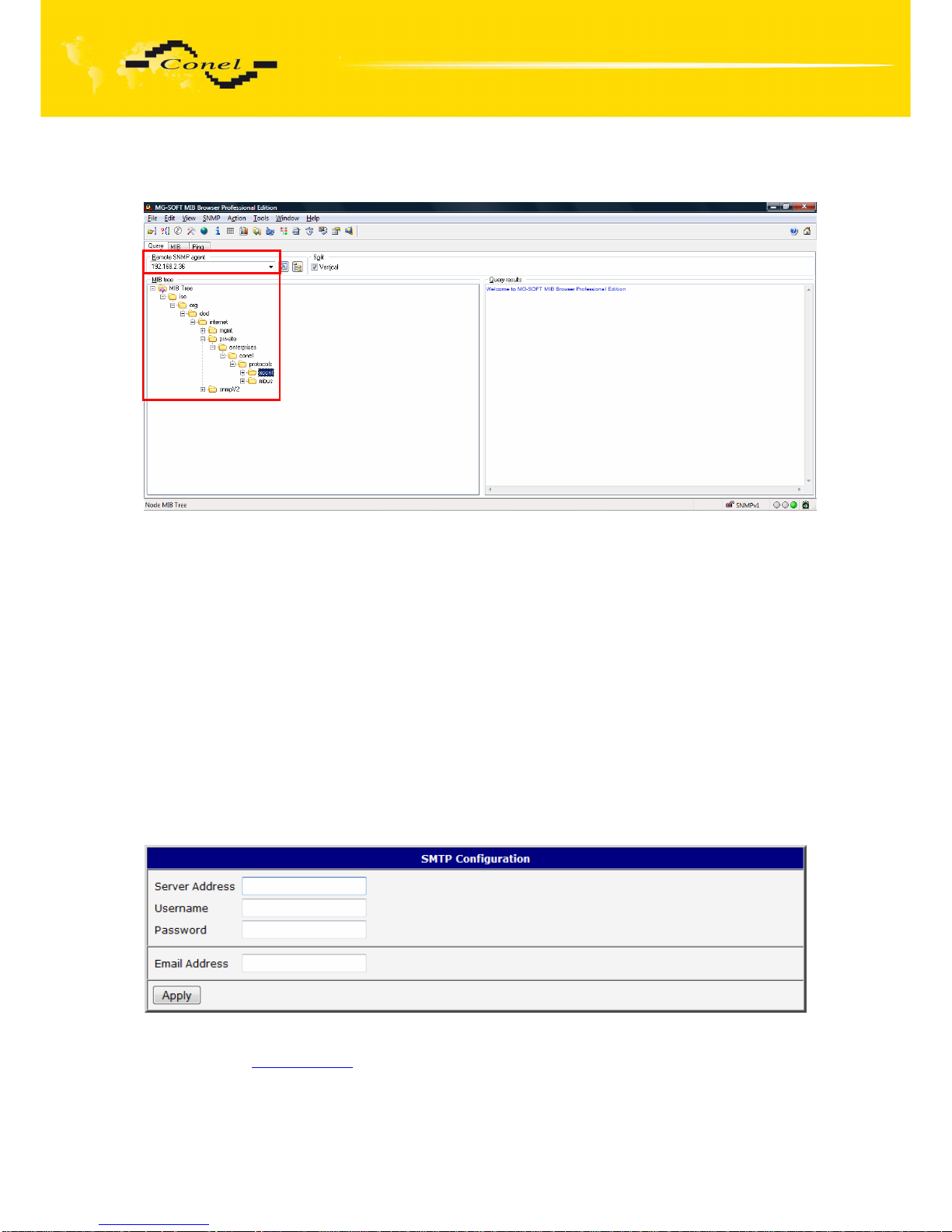
Example of the MIB browser:
It is important to set the IP address of the SNMP agent (router) in field Remote SNMP
agent. After enter the IP address is in a MIB tree part is possible show object identifier.
The path to objects is:
iso->org->dod->internet->private->enterprises->conel->protocols.
5.19. SMTP Configuration
Configuration of SMTP can be entered by clicking on SMTP menu item. In the window,
there is possible to enter login values to e-mail server, from which e-mails will be sent. The
required values are: address of SMTP server (Server Address), login name (Username),
password and e-mail address (Email Address). It is possible to send only one file in
attachment.
After that is possible to send e-mail messages by using this command:
email –T [recipient address] –S[subject] –M[message body] –A[path to attachment]
Example of sending e-mail:
email –T [email protected] –S Test message –M The whole text of message
Page 69

CONFIGURATION
69
5.20. SMS Configuration
In the SMS Configuration menu it is possible to select automatic sending of SMS
messages following power up (Send SMS on power up) and at the start (Send SMS on PPP
connect) or the loss (Send SMS on PPP disconnect) of the PPP connection and at data limit
exceeded (Send SMS when datalimit exceeded). With switch-on parameter Send SMS when
binary input is active it is possible to define SMS for each of four binary inputs in windows
BIN1-SMS, BIN2-SMS, BIN3-SMS and BIN4-SMS, which will be sent if those binary inputs
are active. It is possible to send information to three telephone numbers. Unit ID is the name
of the router that it will send an SMS message to. Unit ID may have a random form.
In the second part of the window it is possible to set function Enable remote control
via SMS. After this it is possible to establish and close PPP connection by SMS message.
This control can be configured for up to three numbers. If is set Enable remote control via
SMS, all incoming SMS are processed and deleted. In the default settings this parameter is
turned on.
If no phone number is filled in, then it is possible to restart the router with the help
of SMS in the form of Reboot from any phone number. While filling of one, two or three
numbers it is possible to control the router with the help of an SMS sent only from these
numbers. While filling of sign “*” it is possible ro control the router with the help of an SMS
sent from every numbers.
Control SMS message doesn’t change the router configuration. If the router is
switched to offline mode by the SMS message the router will be in this mode up to next
restart. This behaviour is the same for all control SMS messages.
It is possible to send controls SMS in the form:
SMS Description
go online sim 1 Switch to SIM1 card
go online sim 2 Switch to SIM2 card
go online Switch router in online mode
go offline PPP connection termination
set out1=0 Set output on 0 on the Expansion port CNT
set out1=1 Set output on 1 on the Expansion port CNT
reboot Router restart
get ip Router send answer with IP address SIM card
Page 70
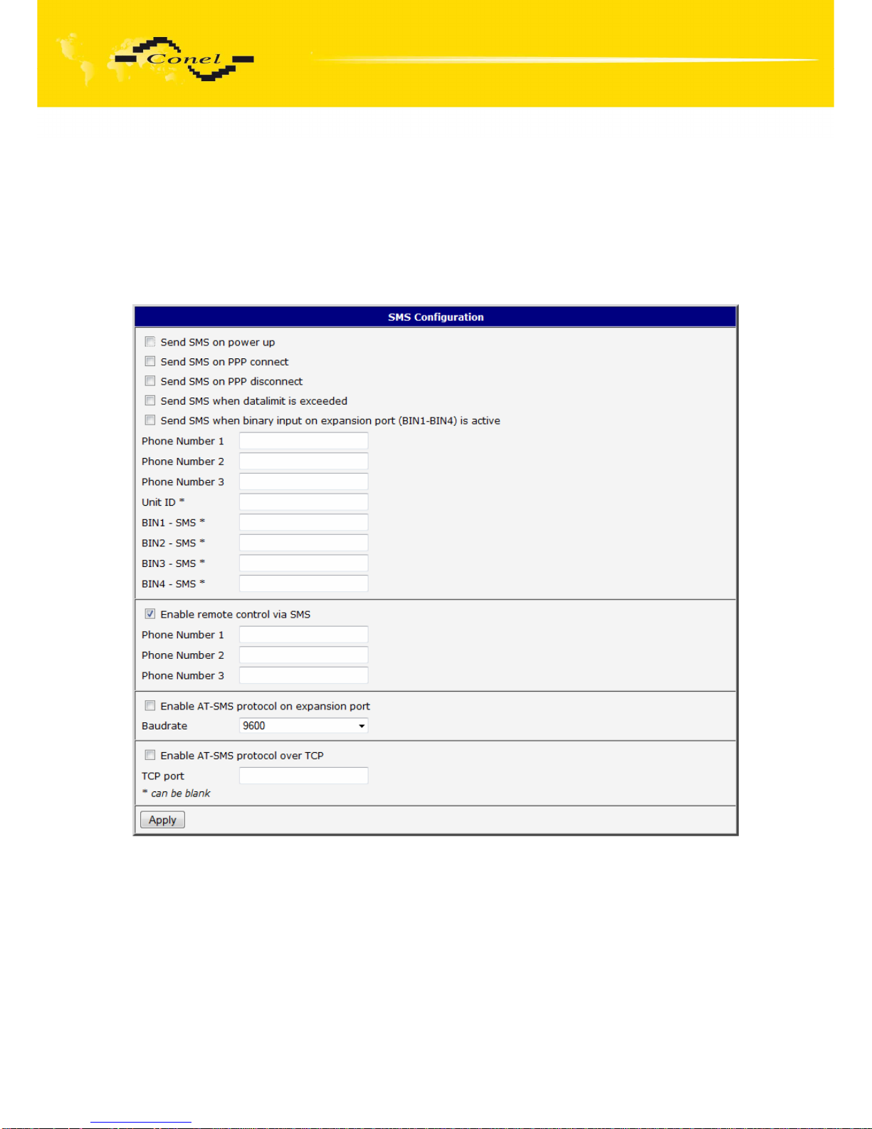
CONFIGURATION
70
By choosing Enable AT-SMS protocol on external port and Baudrate it is possible to
send/receive an SMS on the serial port.
By choosing Enable AT-SMS protocol on TCP port and enter the TCP port it is
possible to send/receive an SMS on the TCP port. SMS messages are sent by the help of a
standard AT commands. More about the AT commands in reference [1].
Choices Enable AT-SMS protocol on external port and Enable AT-SMS protocol
on TCP port mustn’t be chosen at the same time.
Page 71
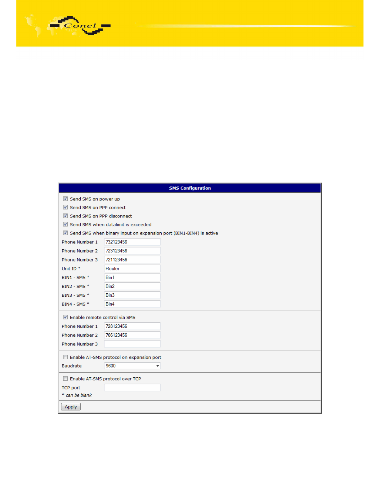
CONFIGURATION
71
After powering up the router, at introduction of the telephone number comes SMS in the
form of:
UR 5 (Unit ID) has been powered up. PLMN:xxxxx,Cell:xxxx,Channel:xx,Level:-xxdBm.
Where PLMN is – number of mobile operator, Cell – number of cell, Channel – used
channel, Level – level signal
After PPP connect, at introduction of the telephone number comes SMS in the form:
UR 5 (Unit ID) has established PPP connection. IP address xxx.xxx.xxx.xxx
After PPP disconnect, at introduction of the telephone number comes SMS in the form:
UR 5 (Unit ID) has lost PPP connection. IP address xxx.xxx.xxx.xxx
Configuration of sending this SMS is following:
Page 72
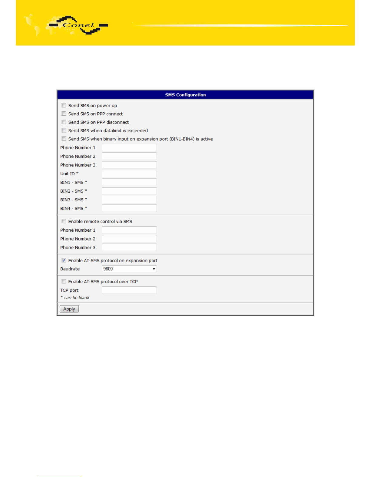
CONFIGURATION
72
Example of the router configuration for SMS sending via serial interface:
Page 73
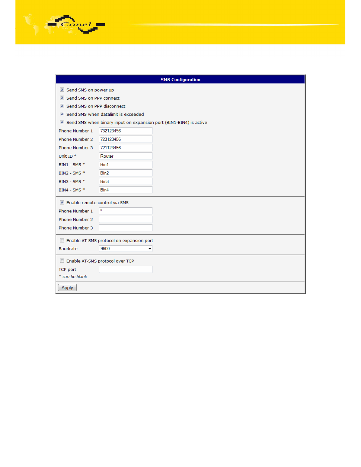
CONFIGURATION
73
Example of the router configuration for controlling via SMS from every phone numbers:
Page 74
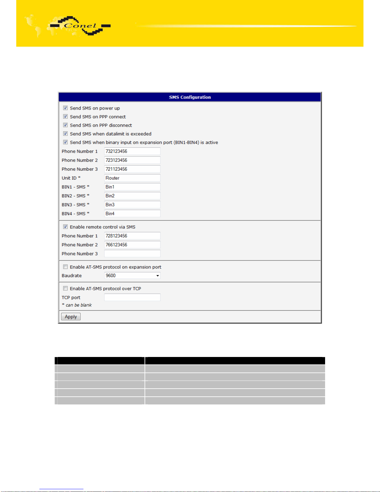
CONFIGURATION
74
Example of the router configuration for controlling via SMS from two phone numbers:
The SMS is possible to do for example in HyperTerminal program. After establishing
connection with the router via serial interface or Ethernet, it is possible to do with SMS by
the help of the next AT commands (more about AT commands see reference [1]):
AT commands Description
AT+CMGF=1 Set the text mode for SMS writing
AT+CMGS=”tel. number” Commands enables to send SMS on entered tel. number
AT+CMGL=ALL List of all SMS messages
AT+CMGR=<index> Read of the definite SMS (all SMS has our index)
AT+CMGD=<index> SMS delete according to index
For the text mode for SMS writing is used command AT+CMGF=1.
AT+CMGF=1 Enter
OK
Page 75

CONFIGURATION
75
The SMS message is created by the help of command AT+CMGS=<tel. number>.
After Enter button is pressed is displayed mark >, behind this mark it is possible to write your
own SMS message. The SMS message is sent by the help of CTRL+Z (SMS sending takes
a few minutes). SMS writing is possible to cancel by pressing Esc.
AT+CMGS=”712123456” Enter
>Hello World! CTRL+Z (keys combination)
OK
It is possible to find the new SMS by the help of command AT+CMGL=ALL. This
command reproaches all SMS messages.
AT+CMGL=ALL Enter
+CMGL: <index>, <status>,<sender number>, ,<date>,<time>
SMS text.
+CMGL: 1,“REC UNREAD“,“+420721123456“, ,“08/02/02, 10:33:26+04“
Hello World!
where <index> is ordinal number of the SMS,
<status> is SMS status:
REC UNREAD – SMS unread
REC READ – SMS read
STO UNSENT – stored unsent SMS
STO SENT – stored sent SMS
ALL – all SMS messages
<sender number> is tel. number from which the SMS was receive,
<date> is date of SMS received,
<time> is time of SMS received.
It is possible to read the new SMS message by command AT+CMGR=<index>.
AT+CMGR=1 Enter
+CMGL: <index>, <status>,<sender number>, ,<date>,<time>
SMS text.
+CMGL: 1,“REC READ“,“+420721123456“, ,“08/01/12, 9:48:04+04“
Hello World!
Received SMS is possible to delete by command AT+CMGD=<index>.
AT+CMGD=1 Enter
OK
Page 76
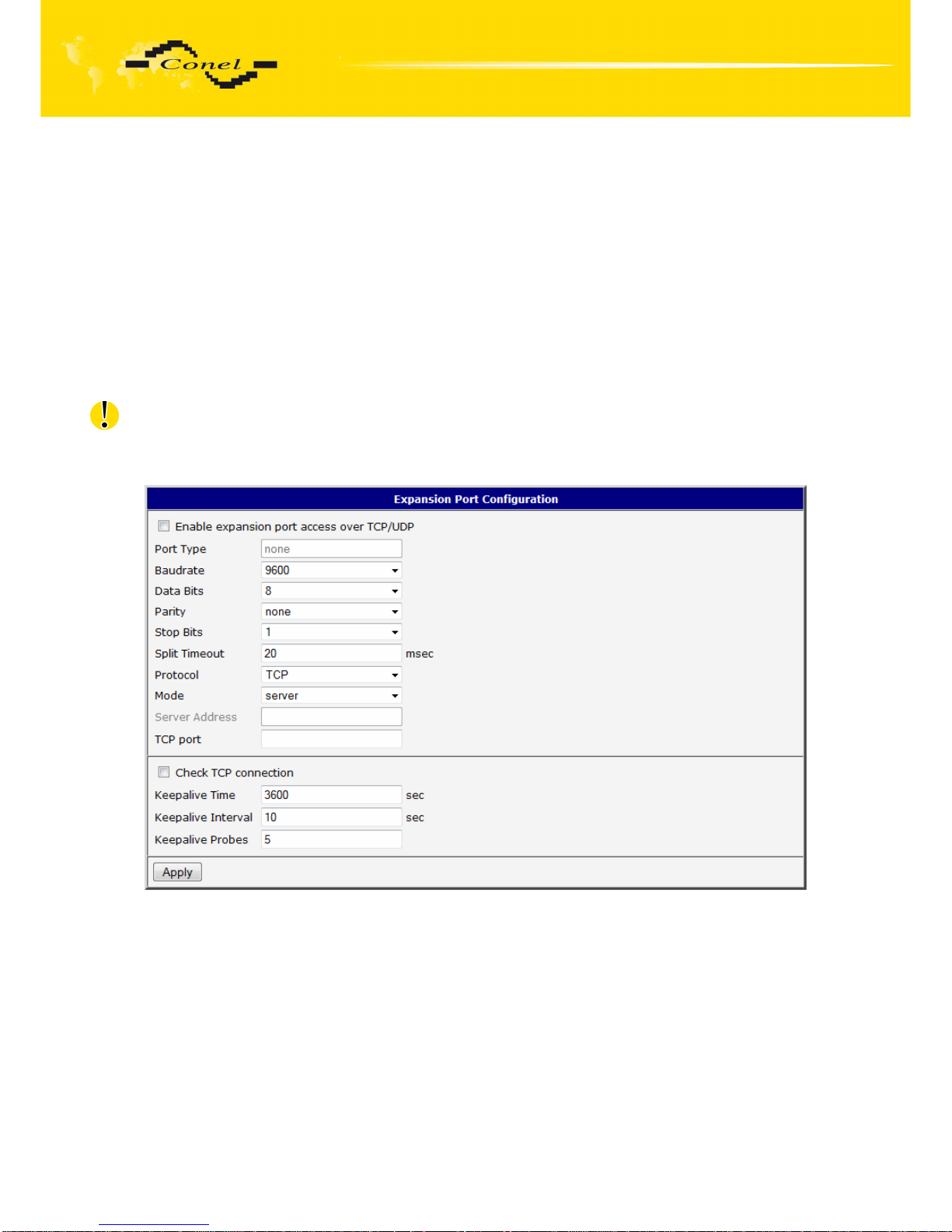
CONFIGURATION
76
5.21. Expansion Port Configuration
The expansion port configuration can be called up by airbrush option External Port
in menu. Inside the window can be defined Baudrate, number of Data bits, Parity, number
of Stop bits, Protocol and Mode. Split timeout is for messages.
In mode TCP server it is necessary to enter the TCP port, on which the router will
listen to incoming requests about TCP connection. In mode TCP client it is necessary to
enter the Server address and final TCP port.
At Check TCP connection it activates verification of coupled TCP connection. Inside
the window can be defined time, after which it will carry out verification of the connection
(Keepalive Time), waiting time on answer (Keepalive Interval) and number of tests
(Keepalive Probes).
In case of M-BUS expansion board installed and when chosen protocol is not M-BUS
or M-BUS TCP then sent data will be returned back to the device! If e.g. LINE protocol is setup on this port, then data will return back to the source.
The changes in settings will apply after pressing the Apply button.
Page 77
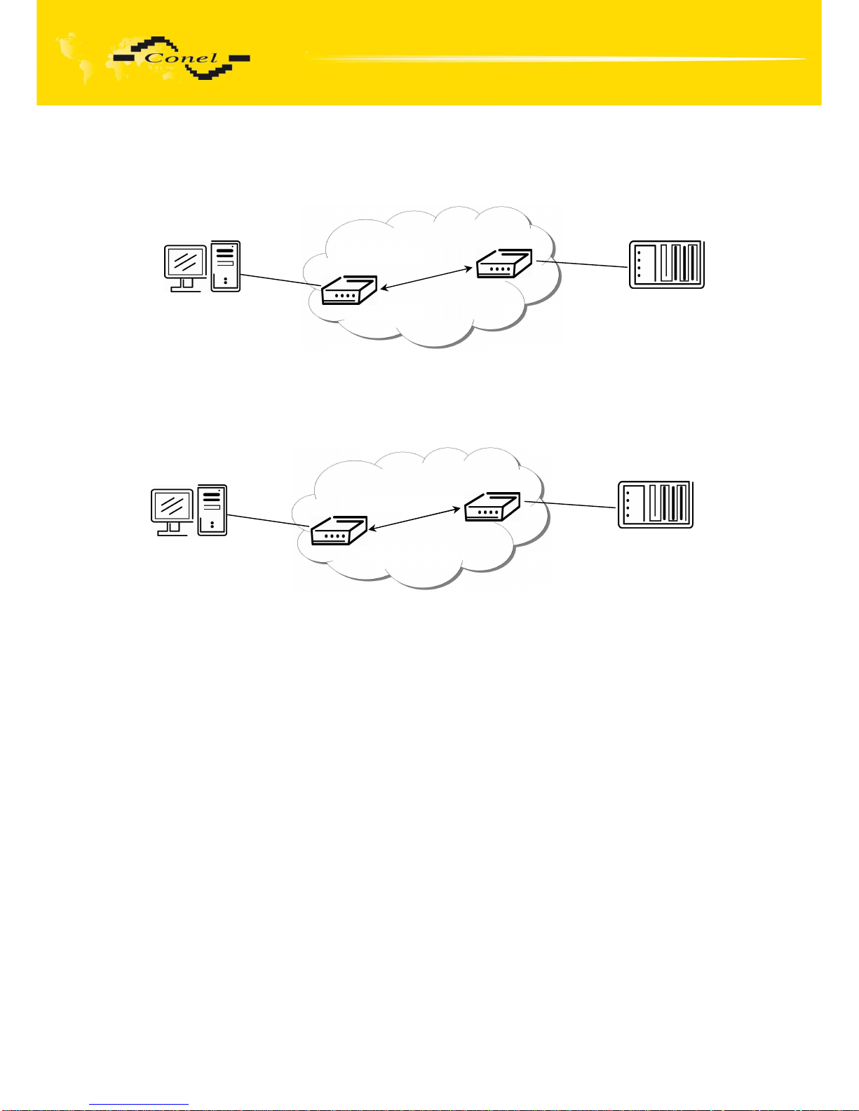
CONFIGURATION
77
Example of external port configuration:
5.22. USB Port Configuration
The USB port configuration can be called up by airbrush option USB Port in menu.
Inside the window can be defined Baudrate, number of Data bits, Parity, number of Stop bits,
Protocol and Mode. Split timeout is for messages.
In mode TCP server it is necessary to enter the TCP port, on which the router will
listen to incoming requests about TCP connection. In mode TCP client it is necessary to
enter the Server address and final TCP port.
At Check TCP connection it activates verification of coupled TCP connection. Inside
the window can be defined time, after which it will carry out verification of the connection
(Keepalive Time), waiting time on answer (Keepalive Interval) and number of tests
(Keepalive Probes).
The changes in settings will apply after pressing the Apply button
ppp0 10.0.0.1
ppp0 10.0.0.2
Settings in the router
Mode: TCP server
Server Address: TCP Port: 2000
RS232
RS232
PC
PLC
Settings in the router
Mode: TCP client
Server Address: 10.0.0.2
TCP Port: 2000
192.168.1.100
ppp0 10.0.0.1
192.168.1.1
ppp0 10.0.0.2
Settings in application on PC:
TCP connection on 10.0.0.2:2000
Settings in the router
Mode: TCP server
Server Address: TCP Port: 2000
ETH
RS232
PC
PLC
Default Gateway 192.168.1.1
Page 78
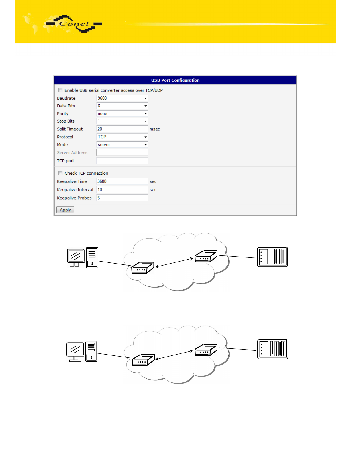
CONFIGURATION
78
Example of USB port configuration:
ppp0 10.0.0.1
ppp0 10.0.0.2
Settings in the router
Mode: TCP server
Server Address: TCP Port: 2000
ETH
USB
PC
Equipment
Settings in the router
Mode: TCP client
Server Address: 10.0.0.2
TCP Port: 2000
192.168.1.100
ppp0 10.0.0.1
192.168.1.1
ppp0 10.0.0.2
Settings in application on PC:
TCP connection on 10.0.0.2:2000
Settings in the router
Mode: TCP server
Server Address: TCP Port: 2000
ETH
USB
PC
Equipment
Default Gateway 192.168.1.1
Page 79
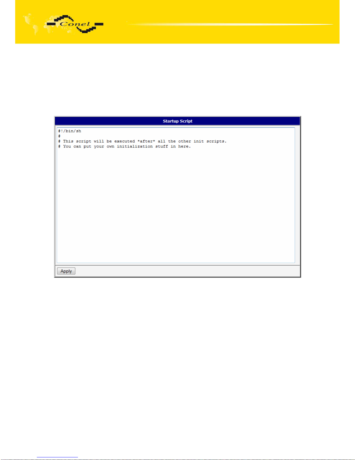
CONFIGURATION
79
5.23. Startup Script
In the window Startup Script it is possible to create own scripts which will be executed
after all initial scripts. This script is not stored or restored when using web interface backup
or restores option.
The changes in settings will apply after pressing the Apply button.
5.23.1.
IO program
Program "io" can be used to set binary outputs (syntax: io set out0|out1 0|1) and get
state of binary inputs (syntax: io get bin0|bin1|bin2|bin3|bin4).
This is an example how to read inputs by using this program:
while true
do
io get bin4
BIN4=$?
if [ "$BIN4" != "$OLD4" ]; then
if [ "$BIN4" = "1" ]; then
gsmsms 739546801 "test SMS bin4-1"
fi
if [ "$BIN4" = "0" ]; then
gsmsms 739546801 "test SMS bin4-0"
fi
OLD4=$BIN4
Page 80

CONFIGURATION
80
fi
sleep 2
io get bin3
BIN3=$?
if [ "$BIN3" != "$OLD3" ]; then
if [ "$BIN3" = "1" ]; then
gsmsms 739546801 "test SMS bin3-1"
fi
if [ "$BIN3" = "0" ]; then
gsmsms 739546801 "test SMS bin3-0"
fi
OLD3=$BIN3
fi
sleep 2
done
Change take effect after restarting router by the help of button Reboot in web
administration or by SMS message.
Page 81
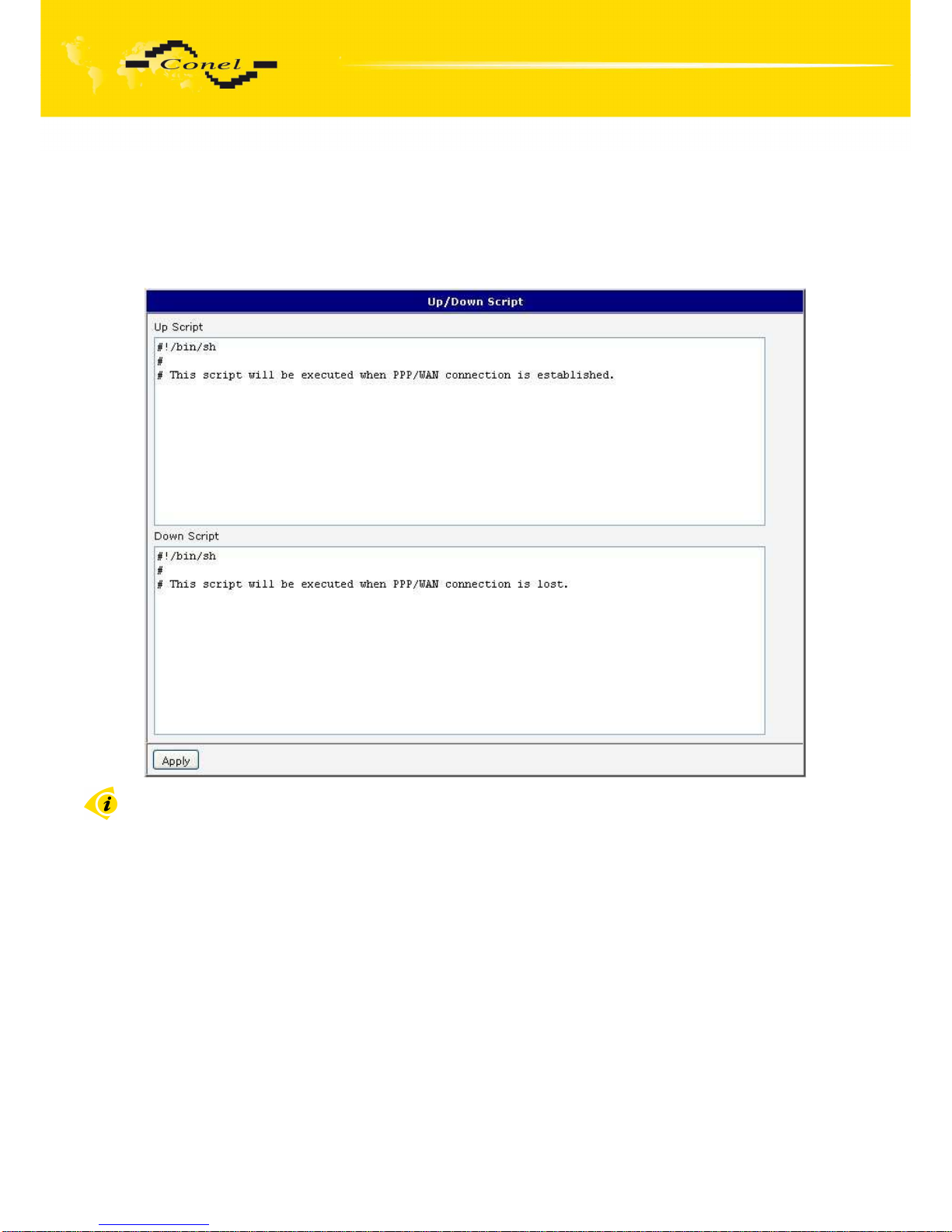
CONFIGURATION
81
5.24. Up/Down Script
In the window Up/Down Script it is possible to create own scripts. In the item Up script
is defined scripts, which begins after establishing a PPP connection. In the item Down Script
is defines script, which begins after lost a PPP connection. This script is not stored or
restored when using web interface backup or restores option.
The changes in settings will apply after pressing the Apply button.
Change take effect after restarting router by the help of button Reboot in web
administration or by SMS message.
5.25. Automatic update configuration
In the window Automatic update it is possible to set automatic configuration update.
This choice enables that the router automatically downloads the configuration
and the newest firmware from the server itself. The configuration and firmware are stores
on the server.
By Enable automatic update of configuration it is possible to enable automatic
configuration update. By parameter Base URL it is possible to enter base part of the domain
or IP address, from which the configuration file will be downloaded. In the case that Unit ID is
empty, the contents of parameter Unite ID or MAC address is added to Base URL.
The configuration file name is from parameter Base URL, hardware MAC address of ETH0
interface and cfg extension. Hardware MAC address and cfg extension is connected
automatically and it isn’t needed to enter this. By parameter Unit ID enabled it defines the
concrete configuration name which will be download to the router. When using parameter
Unit ID, hardware MAC address in configuration name will not be used.
Page 82
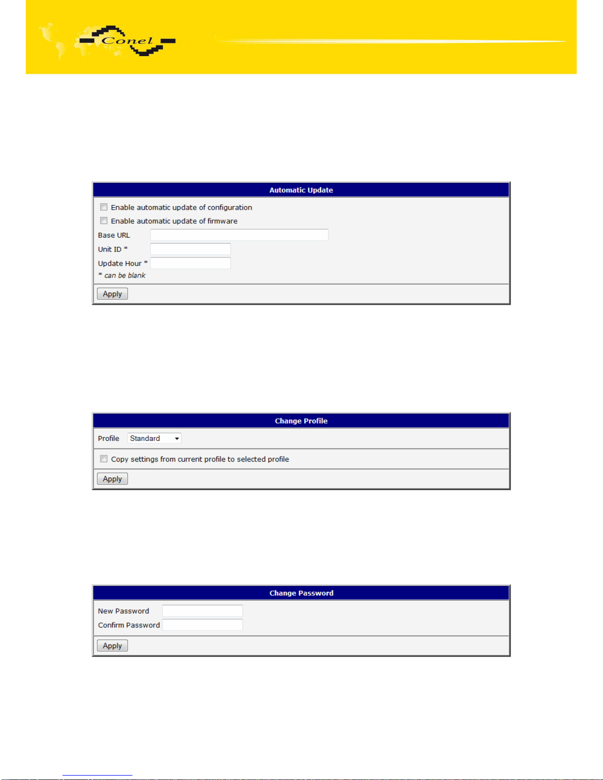
CONFIGURATION
82
Automatic configuration update starts 5 minutes after turning on the router and then
every 24 hours or it is possible to set the time of automatic configuration in parameter Update
Hour. If the entered URL is different configuration than in the router then the router
downloads this configuration and restarts itself.
The changes in settings will apply after pressing the Apply button.
5.26. Change profile
To open the dialog box for changing profile select the Change Profile menu item.
Profile switch is making by press the button Apply. Change take effect after restarting router
by the help of button Reboot in web administration or by SMS message. It is possible select
the standard profile or up to three alternative profiles. It is possible to copy actual
configuration to selected configuration by selecting Copy settings from current profile to
selected profile.
5.27. Change password
To open the dialog box for changing the access password select the Change Password
menu item. The new password will be saved after pressing the Apply button.
In basic settings of the router the password is set on default form root. For higher
security of your network we recommend changing this password.
Page 83
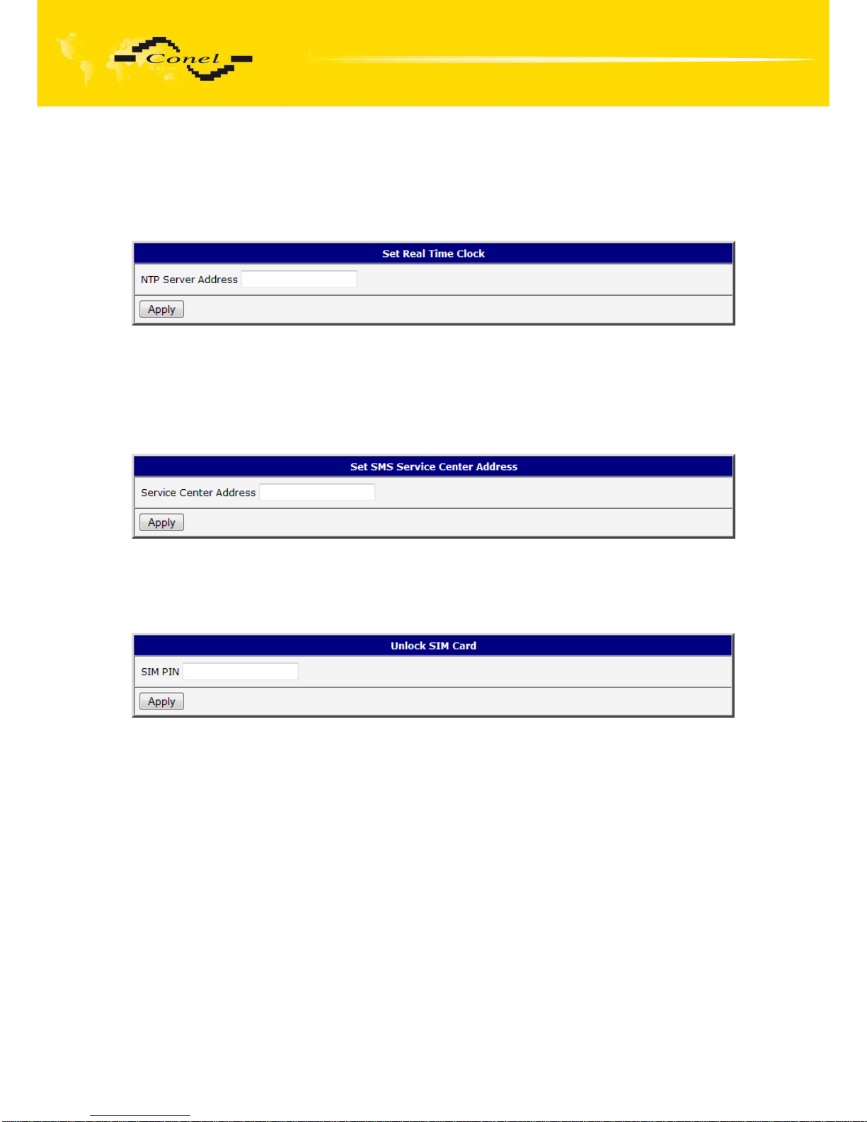
CONFIGURATION
83
5.28. Set real time clock
One - shot inner clock of the router setting can be called up in option Set Real Time
Clock item in the menu. Clocks are set according to the engaged NTP server after push-
button operation Apply.
5.29. Set SMS service center address
In some cases it is needed to set the phone number of the SMS service centre
because of SMS sending. This parameter cannot be set when the SIM card has set phone
number of the SMS service centre. The phone number can be formed without international
prefix xxx xxx xxx or with international prefix for example +420 xxx xxx xxx.
5.30. Unlock SIM card
Possibility to unlock SIM PIN is under Unlock SIM Card item. If the inserted SIM card
is secured by a PIN number, enter the PIN to field SIM PIN and push-button Apply.
Page 84
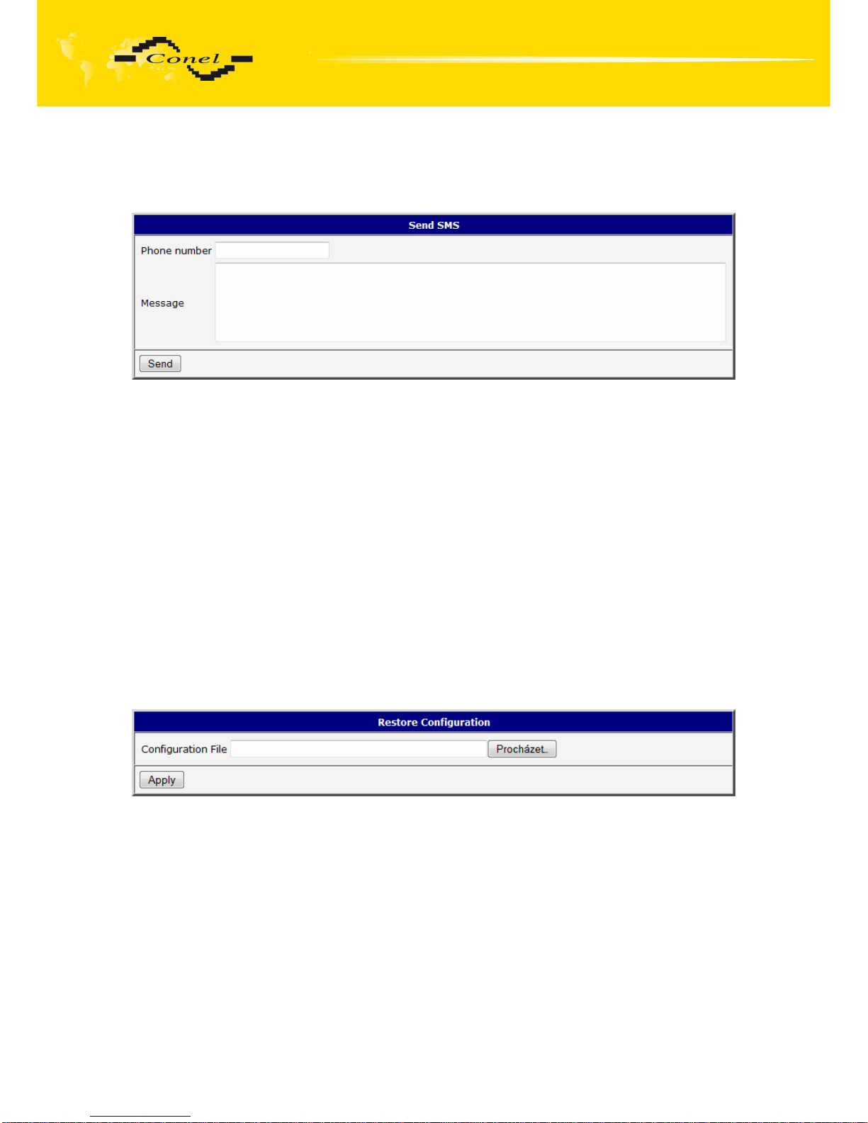
CONFIGURATION
84
5.31. Send SMS
Sending SMS messages is possible in menu Send SMS. The SMS message will be
sent after entering the Phone number and text SMS (Message) and by pushing button Send.
SMS message sending via HTTP request is in the form:
GET /send_exec.cgi?phone=%2B420712345678&message=Test HTTP/1.1
Authorization: Basic cm9vdDpyb290
HTTP request will be sent to TCP connection on router port 80 which sends an SMS
message Test to phone number 420712345678. Authorization is in the format
"user:password" coded by BASE64, example is for root:root.
5.32. Backup Configuration
The router configuration is possible to save by help of the Backup Configuration menu
item. After clicking on this menu it is possible to check a destination directory, where it will
save the router configuration.
5.33. Restore Configuration
In case it is needed to restore the router configuration, it is possible in Restore
Configuration menu item to check configuration by help Browse button.
Page 85
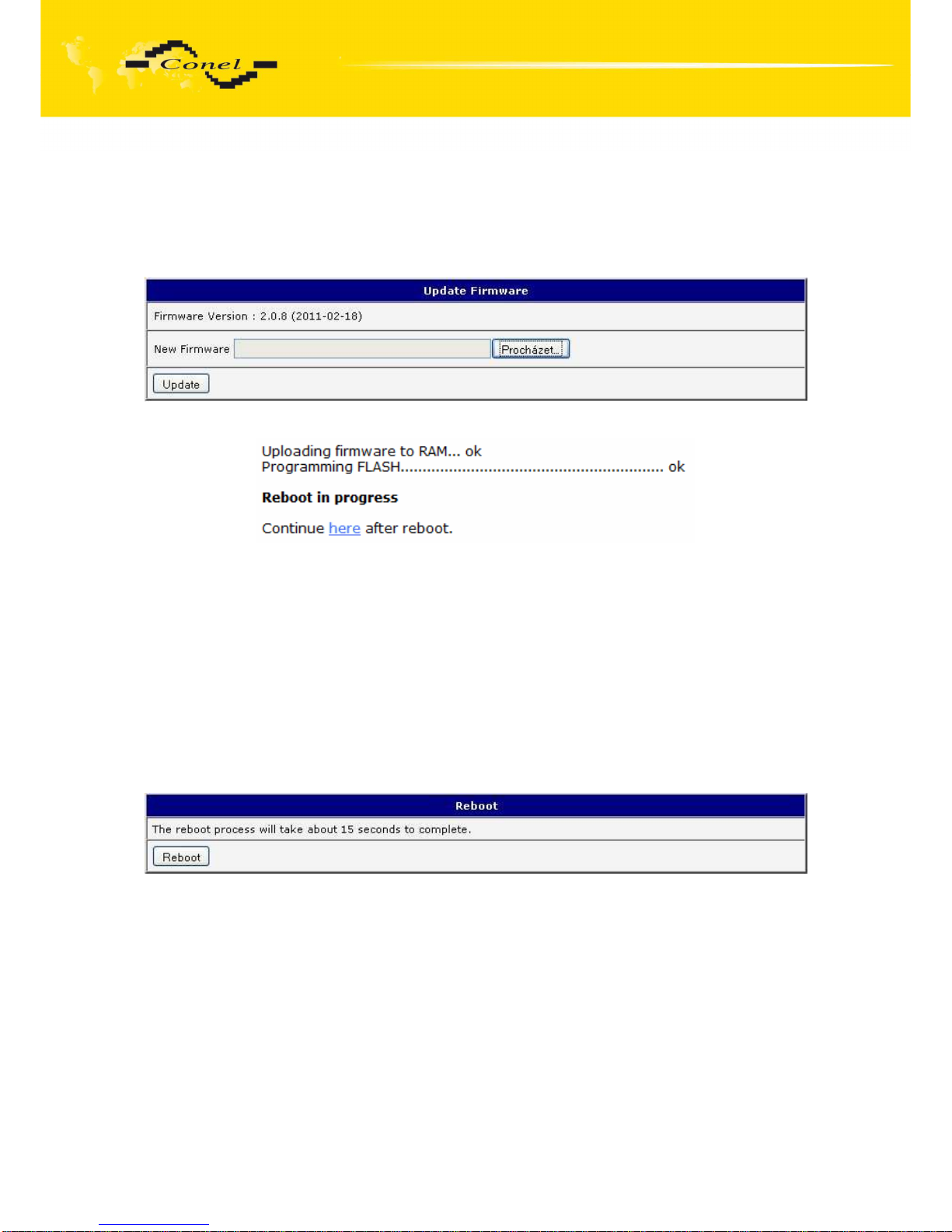
CONFIGURATION
85
5.34. Update firmware
To view the information about the firmware version and instructions for its update select
the Update Firmware menu item. The new firmware will be checked after pressing Browse
button and update the following pressing the Update button.
After successful firmware updating the following statement is listed:
There is information about updating of the FLASH memory.
By firmware actualization from 1.0.5 version the router configuration is remains include
IP address. By actualization older firmware than 1.0.5 the IP address will be set on
192.168.1.1 and all values are in defaults state. From firmware version 2.0.3 is provided simply
file name check of new firmware file. Upload firmware of different device can cause damage of
the router! Total update time lasts for 3 - 4 minutes. During updating of the firmware permanent
power supply has to be maintained. We strongly recommend not using distant update because
of blackout GPRS connection.
5.35. Reboot
To reboot the router select the Reboot menu item and then press the Reboot button.
Page 86
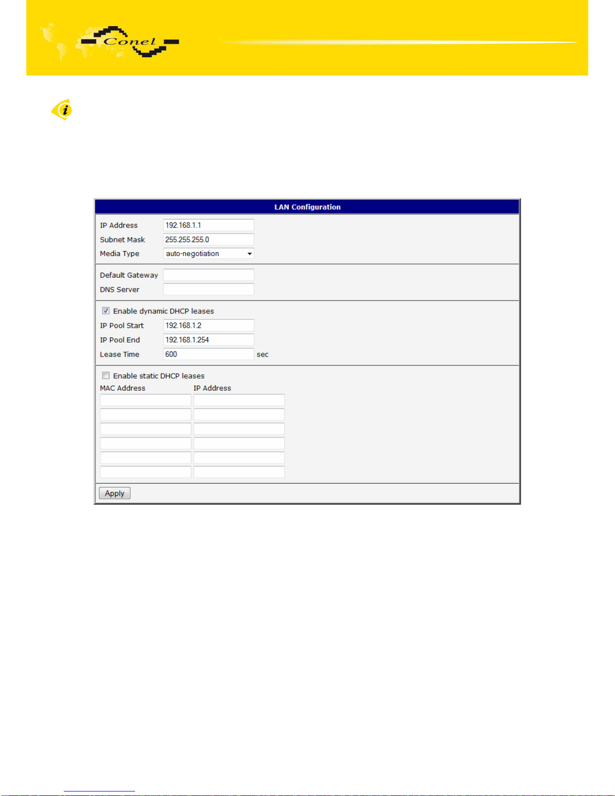
CONFIGURATION
86
5.36. Default settings
After green LED starts to blink it is possible to restore initial settings of the router
by pressing button RST on front panel. After press button RST it is restoration of the
configuration and reset (green LED will be on).
5.36.1.
LAN Configuration
Page 87
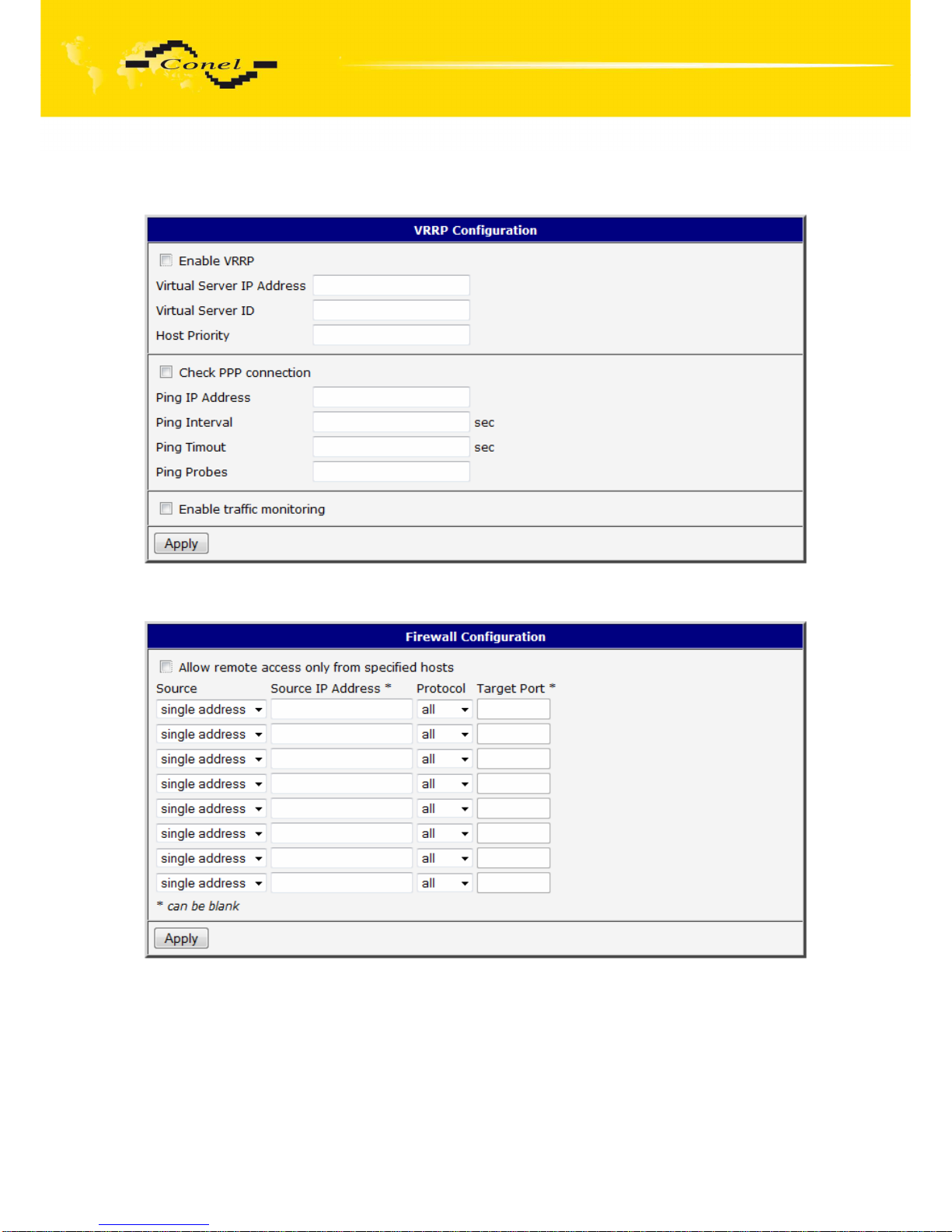
CONFIGURATION
87
5.36.2.
VRRP Configuration
5.36.3.
Firewall Configuration
Page 88
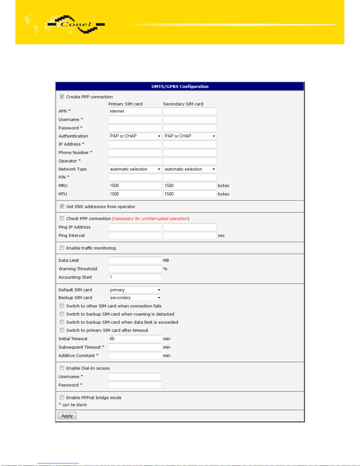
CONFIGURATION
88
5.36.4.
UMTS/GPRS Configuration
Page 89
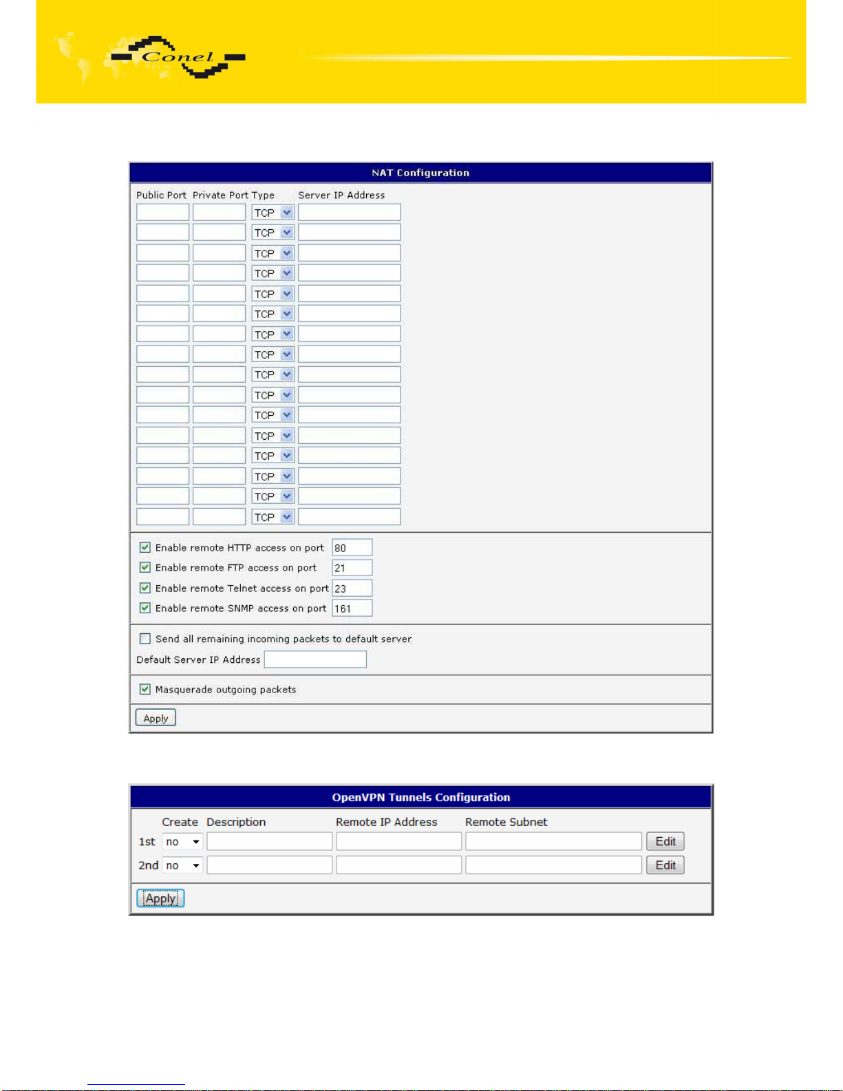
CONFIGURATION
89
5.36.5.
NAT Configuration
5.36.6.
OpenVPN Tunnel Configuration
Page 90
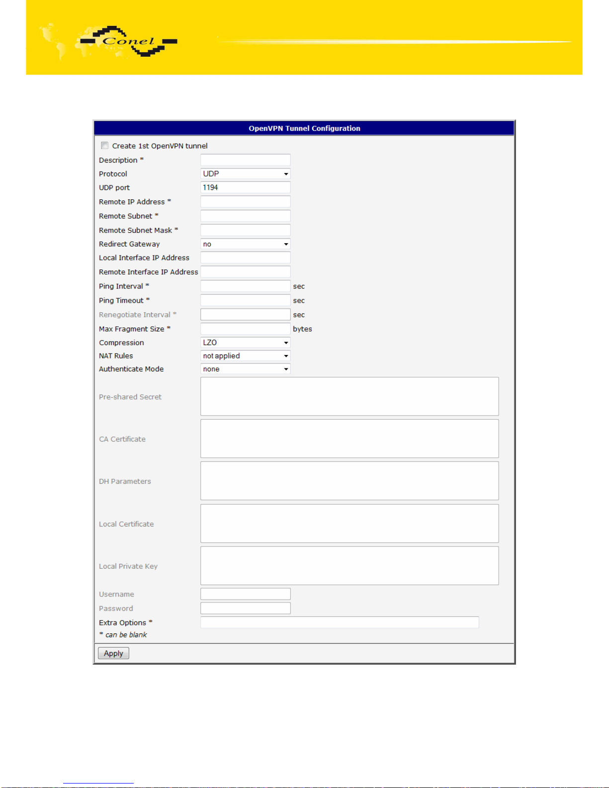
CONFIGURATION
90
Page 91
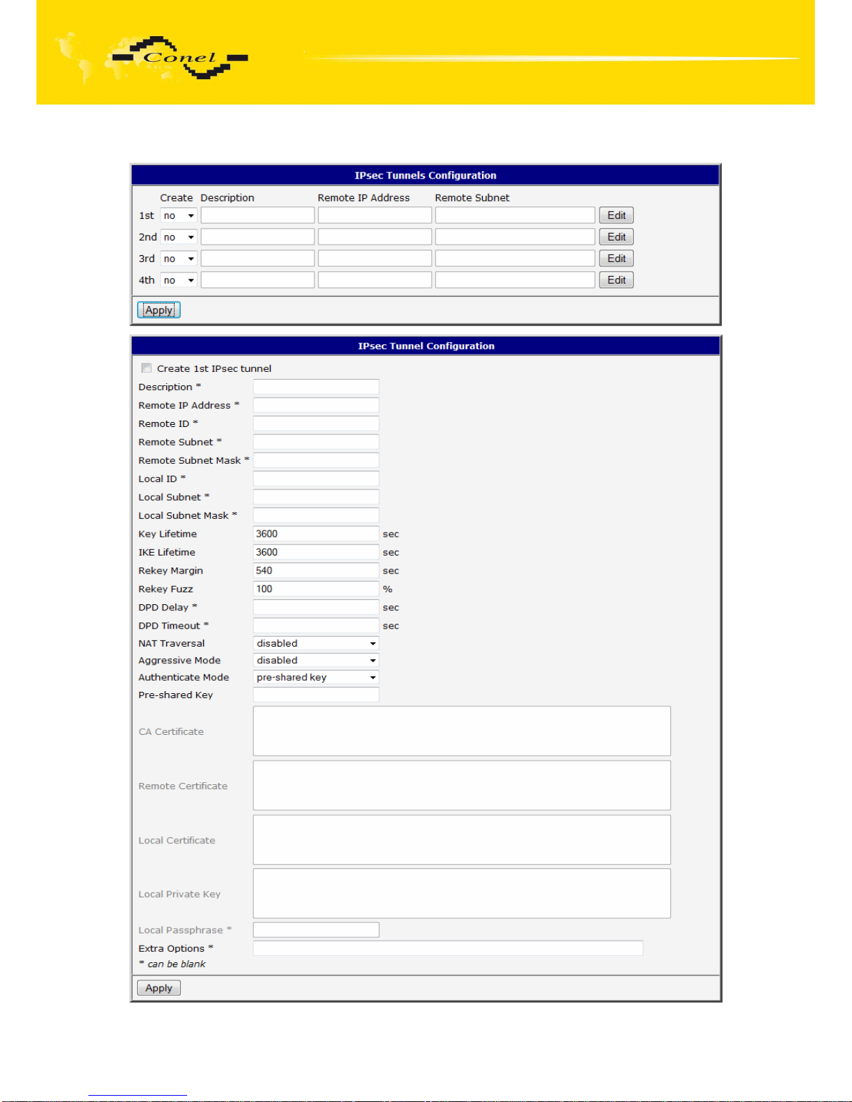
CONFIGURATION
91
5.36.7.
IPsec Tunnel Configuration
Page 92
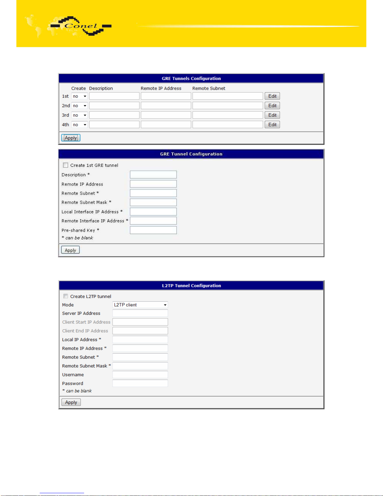
CONFIGURATION
92
5.36.8.
GRE Tunnels Configuration
5.36.9.
L2TP Tunnel Configuration
Page 93
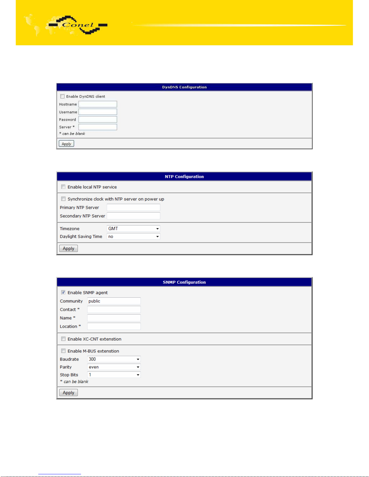
CONFIGURATION
93
5.36.10.
DynDNS Configuration
5.36.11.
NTP Configuration
5.36.12.
SNMP Configuration
Page 94
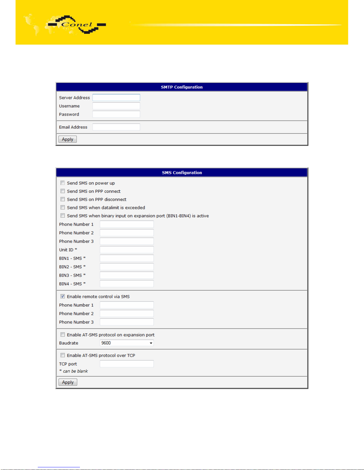
CONFIGURATION
94
5.36.13.
SMTP Configuration
5.36.14.
SMS Configuration
Page 95
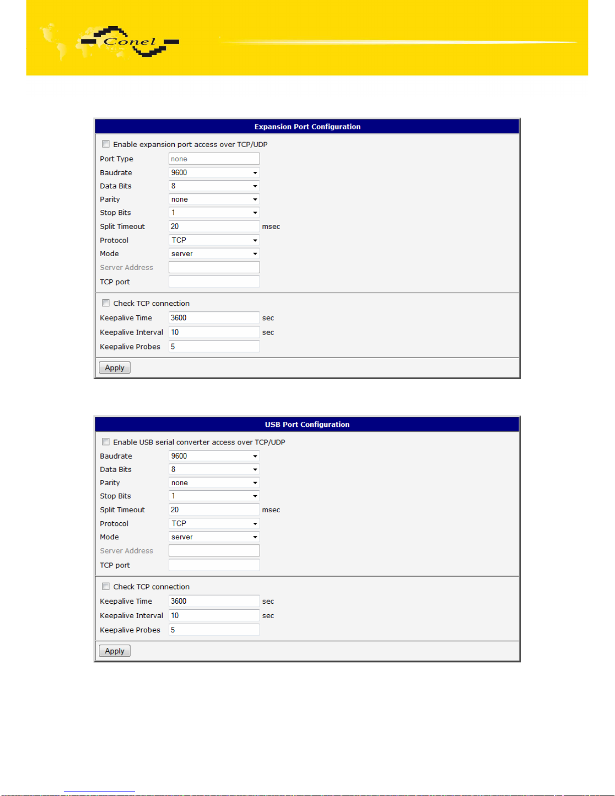
CONFIGURATION
95
5.36.15.
Expansion Port Configuration
5.36.16.
USB Port Configuration
Page 96
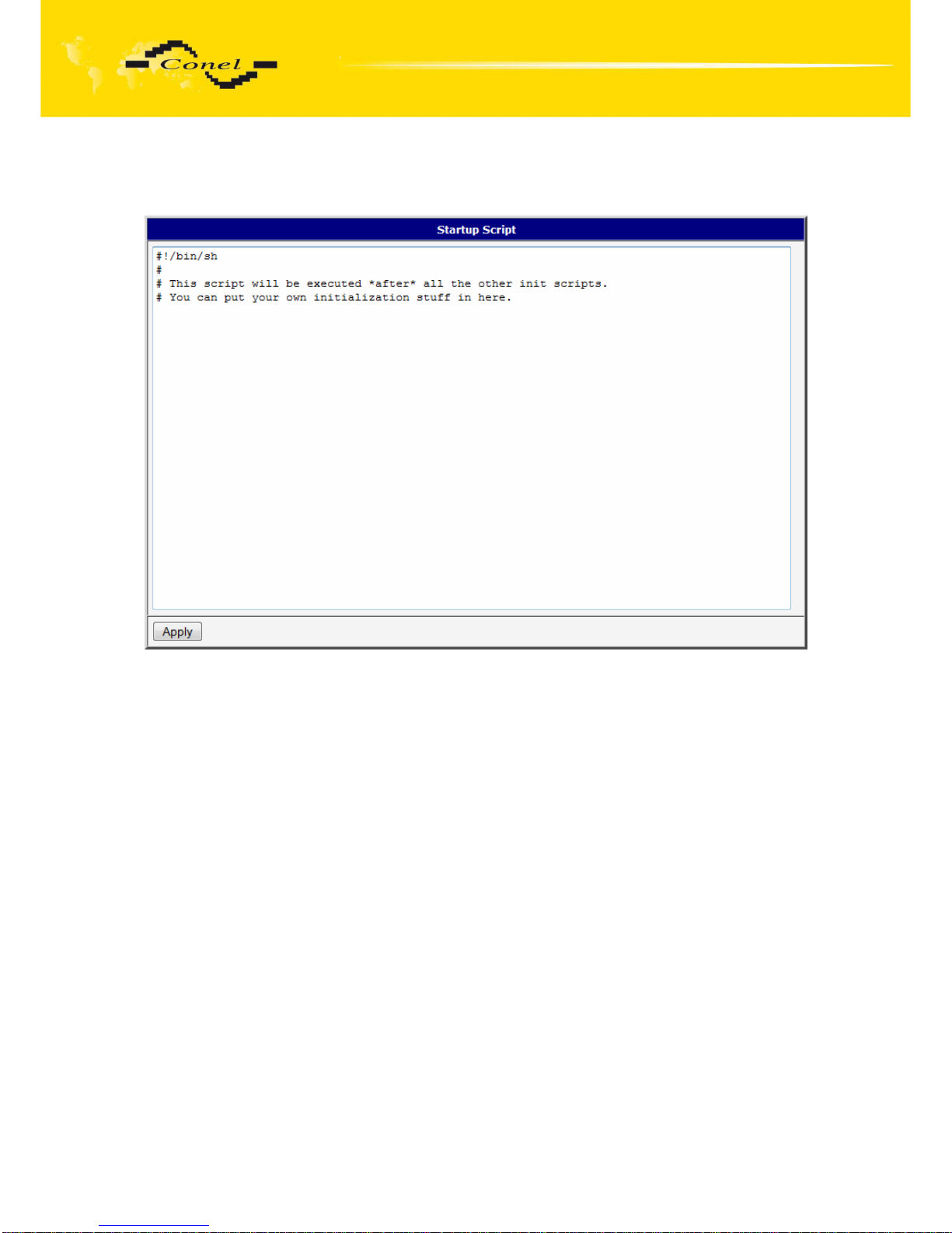
CONFIGURATION
96
5.36.17.
Startup script
Page 97
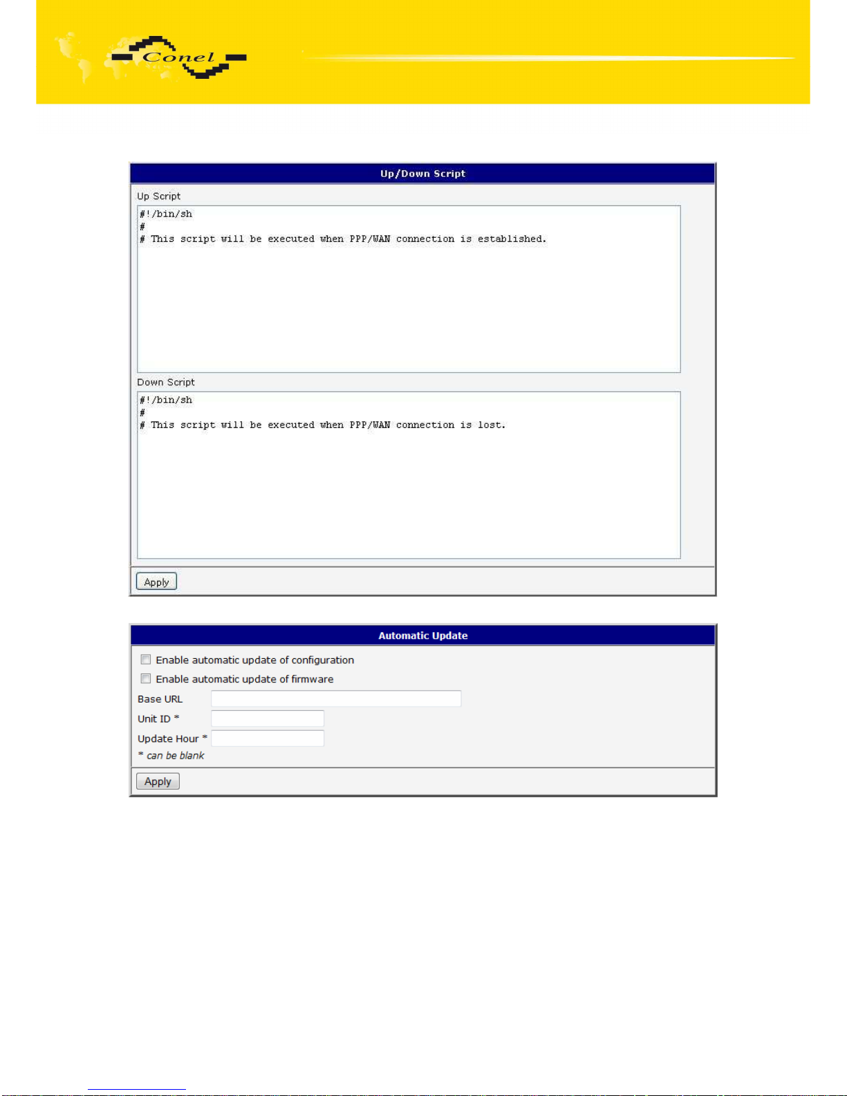
CONFIGURATION
97
5.36.18.
Up/Down script
5.36.19.
Automatic update
Page 98

CONFIGURATION
98
6. Configuration setting over Telnet
Attention! If the SIM card isn’t inserted in the router, it is impossible for the router to
operate. The Included SIM card must be activated for GPRS transmissions. Insert the SIM
card when the router is switched off.
Monitoring of status, configuration and administration of the router can be performed by
means of the Telnet interface. After IP address entry to the Telnet interface it is possible to
configure the router by the help of commands. The default IP address of the modem is
192.168.1.1. Configuration may be performed only by the user "root" with initial password
"root".
For Telnet exists the following commands:
Command Description
cat file contain write
cp copy of file
date show/change of system time
df displaying of informations about file system
dmesg displaying of kernel diagnostics messages
echo string write
free displaying of informations about memory
gsmat AT commend send
gsminfo displaying of informations about signal quality
gsmsms SMS send
hwclock displaying/change of time in RTC
ifconfig displaying/change of interface configuration
io reading/writing input/output pins
ip displaying/change of route table
iptables displaying/modification of NetFilter rules
kill process kill
killall processes kill
ln link create
ls dump of directory contain
mkdir file create
mv file move
ntpdate synchronization of system time with NTP server
passwd password change
ping ICMP ping
ps displaying of processes information
pwd dump of actual directory
reboot restart
rm file delete
rmdir directory delete
route displaying/change of route table
service start/stop of service
sleep pause on set seconds number
slog displaying of system log
tail displaying of file end
tcpdump monitoring of network
touch file create/actualization of file time stamp
vi text editor
Page 99

PROBLEMS, FAG AND
KEEPING
99
7. Possible problems
Some network cards are able to be set in situation, when it is not possible to connect
the router. It is possible to solve this problem in the following steps:
hand by selection communication rates 10 MB/s in property network cards,
connect router over switch,
start computer only after finalizing the start of the router.
8. Reference
[1] Cinterion: EU3-E_ATC_V00.295 – AT command Set, 2010
9. FAQ
I can’t get from internet on equipment, which is connected to router and I have NAT
enabled.
The device's gateway has to be configured as the router.
Router resets itself, connection on Ethernet fails.
It is necessary to use an antenna, which will be situated far from power supply.
I don’t get on web server at NAT.
The remote http access of the router has to be disabled, default server address
has to be your web server and the gateway of the web server has to be the IP
of router.
PPP connection fails.
Check signal power. If signal power is weak, you will have to use a better
antenna. If the environmental cells have a similar signal it will be necessary to
use a directive antenna. Signal levels have to be in the range -50dBm and 90dBm.
It is necessary to set ping, which will check the connection and, in the case of fail
ping, restart connection.
PPP connection won't be established.
Recheck GPRS settings - APN, name, password and IP address.
Try to enter PIN – verification if the SIM card hasn’t set PIN code.
In private APN it is appropriate to switch the DNS server send off.
Switch log system on and observe where the error turns up.
Connection fails on Ethernet or connection isn’t establishing.
On ethernet interface of the router it is possible to switch auto negotiation off and
set a rate and duplex by hand.
DynDNS not function.
In private APN not functional.
If the same IP address is recorded in your canonic name as dynamically assign
address, it means that the operator is using NAT or firewall.
NAT is possible to verify by the help of the ping on address of your server with
static IP address and by the help of the router address verify and address in ping.
Firewall is possible to verify, for example by remote access on web interface.
Page 100

PROBLEMS, FAG AND
KEEPING
100
The operator doesn’t give out address DNS servers and without DNS server’s it
is impossible to connect to server dyndns.org. In log system will be this message:
DynDNS daemon started,
Error resolving hostname: no such file or directory,
Connect to DynDNS server failed.
IPSec tunnel is establishing but communication doesn’t function.
Probably it is badly set up route conditionals of connected equipment or it is bad
set up GW.
FTP doesn’t function.
Router doesn’t support the active FTP mode, supports the passive mode only.
RS232 doesn’t function.
It is necessary to verify present the expansion port RS232.
Verify present the expansion port RS232 in router configuration in menu „external
port“, or verify connection locally by the help Telnet-Hyper terminal.
L2TP or IPSec isn’t establishing.
Verify the reason in the log system.
I switched the router to offline mode by the SMS message, but the router is in online
mode after restart.
Control SMS message doesn’t change the router configuration. If the router is
switched to offline mode by the SMS message the router will be in this mode up
to next restart. This behaviour is the same for next all control SMS messages.
10. Customers support
Up to date information about the product is on website:
http://www.conel.cz/
Upkeep-advices:
The SIM-card must be handled carefully as with a credit card. Do not bend, do not scratch on
this and do not expose to static electricity.
During cleaning of the modem do not use aggressive chemicals, solvents and abrasive
cleaners!
Conel Company hereby declares that the modem narrated in this user’s guide fits all basic
demands of directive 1999/5/EC (R&TTE).
Modem fits values of coefficient SAR defined by association ICNIRP and values of “About
protection of health before non-ionized radiation“.
Declaration about consistency was issued and is possible get it at
producer.
 Loading...