

Page 1
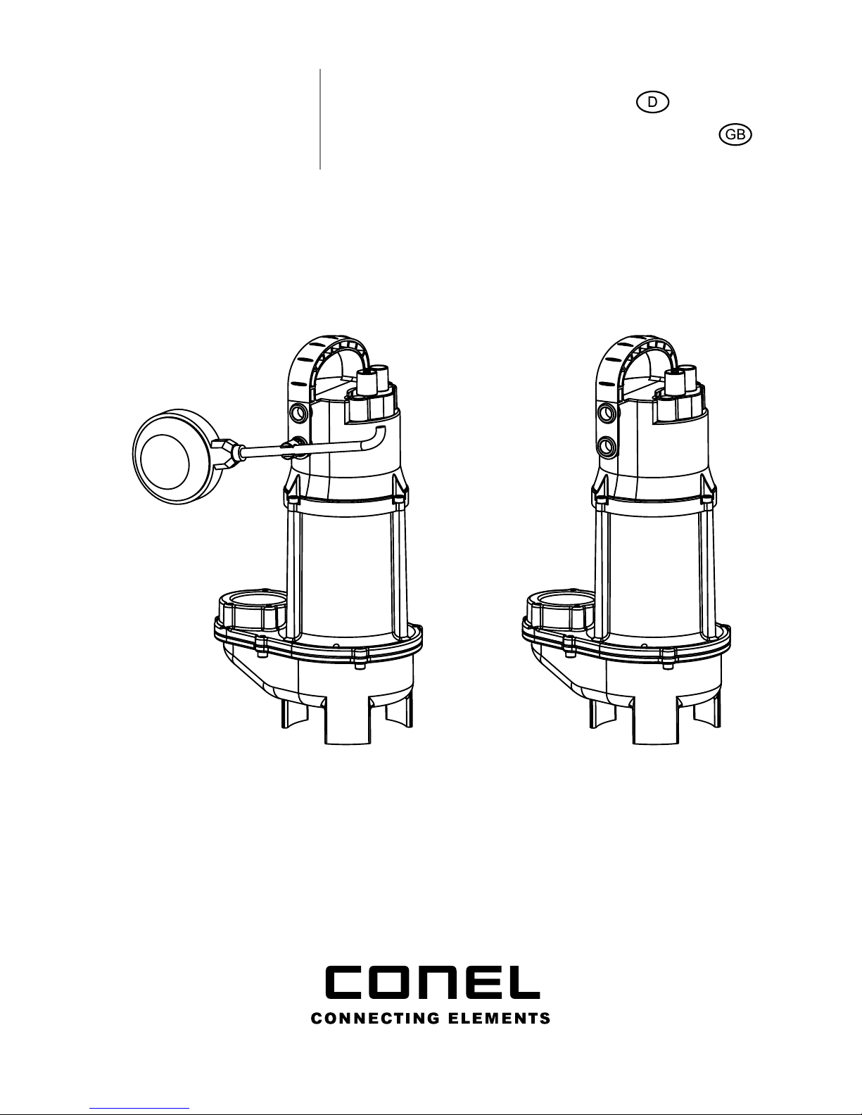
FLOW
Tauchpumpe 30 | Betriebsanleitung
Submersible pump 30 | Operating instructions
KBN: FLOWTP30 KBN: FLOWTP30 OS
Page 2

EG Konformitätserklärung | EC Certicate of Conformity
CONEL GmbH
Margot-Kalinke-Straße 9 · 80939 München
erklärt in alleiniger Verantwortung, dass
das Produkt
declare in sole responsibility, that
the product
FLOW Tauchpumpe 30
KBN: FLOWTP30
auf das sich diese Erklärung bezieht,
den einschlägigen grundlegenden
Sicherheits- und Gesundheitsanforde-
rungen der EG-Richtlinien entsprechen
2006/95/EC · 2004/108/EC.
to which this certicate applies, conforms to the basic health and safety requirements of EEC Directives 2006/95/
EC · 2004/108/EC.
Angewendete harmonisierte Normen,
insbesondere
Applied harmonized standards in
particular
DIN EN 12050-2 · EN 60335
11.01.2012
Unterschrift Geschäftsführer
11 / 01 / 2012
Signature Managing Director
Detlef Greunke
2
Page 3

Inhalt
EG Konformitätserklärung | EC Certicate of Conformity Seite 2
DE FLOW Tauchpumpe 30 Seite 3
1. Sicherheit Seite 4
1.1 Kennzeichnung von Hinweisen in der Betriebsanleitung Seite 5
1.2 Sicherheitsbewusstes Arbeiten Seite 5 - 6
1.3 Eigenmächtiger Umbau und Ersatzteilherstellung Seite 6
1.4 Unzulässige Betriebsweisen Seite 6
2. Lieferumfang Seite 7
3. Einsatz Seite 7
4. Werkstoffe Seite 7
5. Technische Daten Seite 8
6. Transport Seite 9
7. Elektroanschluss Seite 9
8. Aufstellung/Einbau Seite 10
9. Inbetriebnahme Seite 11
10. Wartung Seite 12
11. Anhang Seite 12 - 13
12. Ersatzteile Seite 14
EN FLOW Submersible pump 30 Seite 15+
3
Page 4

4
1. Sicherheit
In Anlehnung an das VDMA-Einheitsblatt 24292 (VDMA = Verband Deutscher Maschinen- und Anlagenbau e.V.).
Dieses Gerät kann von Kindern ab 8
Jahren und darüber sowie von Personen
mit verringerten physischen, sensorischen
oder mentalen Fähigkeiten oder Mangel
an Erfahrung und Wissen benutzt werden,
wenn sie beaufsichtigt oder bezüglich
des sicheren Gebrauchs des Gerätes
unterwiesen wurden und die daraus
resultierenden Gefahren verstehen.
Kinder dürfen nicht mit dem Gerät spielen.
Reinigung und Benutzer-Wartung dürfen
nicht von Kindern ohne Beaufsichtigung
durchgeführt werden.
Diese Betriebsanleitung enthält grundlegende Hinweise, die bei Aufstellung, Betrieb
und Wartung zu beachten sind. Daher ist diese Betriebsanleitung unbedingt vor Montage und Inbetriebnahme zu lesen und muss ständig am Einsatzort des Aggregats/der
Anlage verfügbar sein.
Es sind nicht nur die unter diesem Hauptpunkt Sicherheit aufgeführten, allgemeinen
Sicherheitshinweise zu beachten, sondern auch die unter den anderen Hauptpunkten
eingefügten, speziellen Sicherheitshinweise.
Sicherheit
Page 5

5
1.1 Kennzeichnung von Hinweisen in der Betriebsanleitung
Die in dieser Betriebsanleitung enthaltenen Sicherheitshinweise, die bei Nichtbe-
achtung Gefährdungen für Personen hervorrufen können, sind mit einem allgemei-
nen Gefahrensymbol, Sicherheitszeichen nach DIN 4844-W 9, gekennzeichnet.
Bei Warnung vor elektrischer Spannung erfolgt die Kennzeichnung mit Sicherheits-
zeichen nach DIN 4844-W 8.
Direkt am Aggregat angebrachte Hinweise wie z. B.
> Drehrichtungspfeil
> Typenschild
müssen unbedingt beachtet und in vollständig lesbarem Zustand gehalten werden.
Gefahren bei Nichtbeachtung der Sicherheitshinweise
Die Nichtbeachtung der Sicherheitshinweise kann sowohl eine Gefährdung für Personen als auch für Umwelt und Aggregat zur Folge haben. Die Nichtbeachtung der
Sicherheitshinweise kann zum Verlust jeglicher Schadenersatzansprüche führen.
Im Einzelnen kann Nichtbeachtung beispielsweise folgende Gefährdung nach sich
ziehen:
> Versagen wichtiger Funktionen des Aggregats/der Anlage.
> Gefährdung von Personen durch elektrische, mechanische und
chemische Einwirkungen.
> Gefährdung der Umwelt durch Leckage von gefährlichen Stoffen.
1.2 Sicherheitsbewusstes Arbeiten
Die in dieser Betriebsanleitung aufgeführten Sicherheitshinweise, die bestehenden
nationalen Vorschriften zur Unfallverhütung sowie eventuelle interne Arbeits-, Betriebsund Sicherheitsvorschriften des Betreibers sind zu beachten.
Kennzeichnung von Hinweisen in der Betriebsanleitung / Sicherheitsbewusstes Arbeiten
Page 6

6
Sicherheitshinweise für den Betreiber/Bediener
Gefährdungen durch elektrische Energie sind auszuschließen (Einzelheiten hierzu
siehe z. B. in den Vorschriften des VDE und der örtlichen Energieversorgungsunternehmen).
Sicherheitshinweise für Wartungs-, Inspektions- und Montagearbeiten
Der Betreiber hat dafür zu sorgen, dass alle Wartungs-, Inspektions- und Montage-
arbeiten von autorisiertem und qualiziertem Fachpersonal ausgeführt werden, das
sich durch eingehendes Studium der Betriebsanleitung ausreichend informiert hat.
Grundsätzlich sind Arbeiten an dem Aggregat nur im Stillstand durchzuführen. Pumpen
oder Aggregate, die gesundheitsgefährdende Medien fördern, müssen dekontaminiert
werden.
Unmittelbar nach Abschluss der Arbeiten müssen alle Sicherheits- und Schutzeinrichtungen wieder angebracht bzw. in Funktion gesetzt werden. Vor der Wiederinbetriebnahme sind die in dieser Betriebsanleitung aufgeführten Punkte zu beachten.
1.3 Eigenmächtiger Umbau und Ersatzteilherstellung
Umbau oder Veränderungen des Aggregats/der Anlage sind nur nach Absprache mit
dem Hersteller zulässig. Originalersatzteile und vom Hersteller autorisiertes Zubehör
dienen der Sicherheit. Die Verwendung anderer Teile kann die Haftung für die daraus
entstehenden Folgen aufheben.
1.4 Unzulässige Betriebsweisen
Die Betriebssicherheit des gelieferten Aggregats ist nur bei bestimmungsgemäßer
Verwendung entsprechend dieser Betriebsanleitung gewährleistet. Die angegebenen
Grenzwerte dürfen auf keinen Fall überschritten werden. Mit dieser Einbau- und Betriebsanleitung werden hier nicht genannte allgemeine Vorschriften und Normen nicht
außer Kraft gesetzt.
Sicherheitsbewusstes Arbeiten / Eigenmächtiger Umbau / Unzulässige Betriebsweisen
Page 7

7
2. Lieferumfang
KBN: FLOWTP30
Anschlussfertige Tauchpumpe mit 10 m Kabel mit Schutzkontaktstecker, angebautem
Schwimmerschalter, Druckabgang mit Innengewinde 1½" sowie 1¼" mit Außengewinde.
KBN: FLOWTP30 OS
-Anschlussfertige Tauchpumpe mit 10 m Kabel mit Schutzkontaktstecker,
Druckabgang mit Innengewinde 1½" sowie 1¼" mit Außengewinde, für Schaltanlagen-
betrieb.
3. Einsatz
> Tauchpumpen der Baureihe FLOW Tauchpumpe 30 sind zur Förderung von Klar-
wasser, Regenwasser sowie fäkalienfreiem, häuslichem Abwasser mit Feststoffen
(freier Kugeldurchgang max. 30 mm Durchmesser) bzw. einem Feststoffanteil bis
max. 0,5 % geeignet.
> Die Pumpen dürfen nicht zur Förderung von korrosiven, brennbaren, gasenden
und explosionsgefährlichen Medien sowie fäkalienhaltigem Abwasser eingesetzt
werden.
> Sandhaltige oder andere, schleißende Medien verkürzen die Lebensdauer der
Pumpen.
> Nicht bestimmt für Kondensate aus Brennwertgeräten sowie Sole aus
Enthärtungsanlagen.
> Der Geräuschemissionswert ist kleiner als 70 dB (A).
> Wenn durch Ausfall der Hebeanlage Schaden entstehen kann, z. B. bei Strom-
ausfall oder technischem Defekt, ist die Anwendung entsprechend abzusichern
(Notstromversorgung, Doppelpumpstation, netzunabhänger Alarm usw.).
4. Werkstoffe
Werkstoffe
Pumpengehäuse EN-GJL-250
Laufrad Polyamid
Dichtungen NBR
Motorwelle Edelstahl 1.4057 (AISI 431)
Oberer Deckel Polypropylen (PP)
Schrauben Edelstahl 1.4401 (AISI 316)
Lieferumfang / Einsatz / Werkstoffe
Page 8

8
5. Technische Daten
Technische Daten
Artikelnummer FLOWTP30 & FLOWTP30 OS
Druckabgang
> G 1½" IG
> Adapter G 1¼" AG
Freier Durchgang 30 mm
Max. Förderstrom (bei 1 m) 18 m
3
/h
Max. Förderhöhe (bei 0 m
3
/h) 8,5 m
Anschlusskabel (steckbar / EasyFit) H07RN-F 3G1.0
Gleitringdichtung Siliziumkarbid / Kohle
Kabellänge 10 m
Gewicht Ca. 8,5 kg
Spannung/Frequenz 1 x 230 V/50 Hz
Stromart Wechselstrom
Nennstrom 3,6 A
Motorleistung P1 0.8 kW
Drehzahl 2900 min
-1
Motorschutz Temperaturwächter in Wicklung eingebaut
Stecker Schutzkontaktstecker
Schutzart IP 68
Isolationsklasse Motor B
Auslöstemperatur Motorschutz 120 °C
Maximale Eintauchtiefe 10 m
Fördermediumtemperatur Max. 40 °C (60 °C für 5 Minuten)
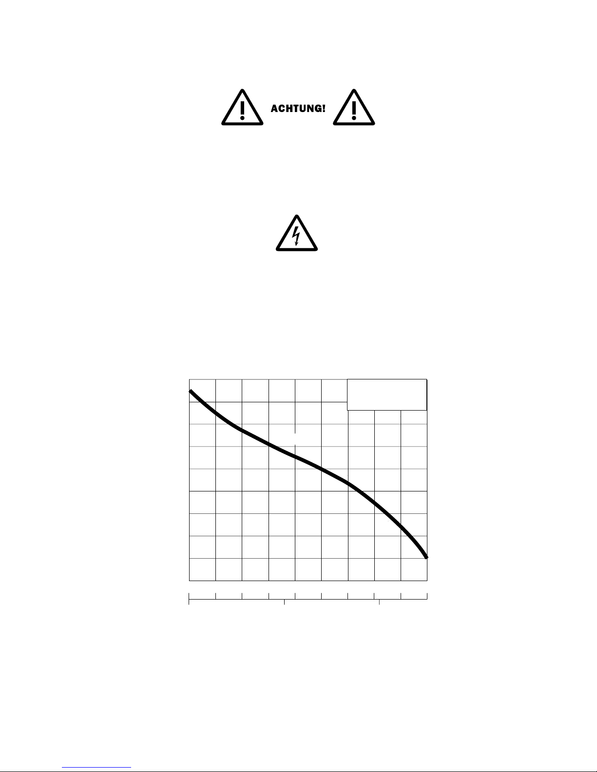
Kennlinie – Siehe Seite 12 Abbildung 2, Abmessungen – Siehe Seite 13 Abbildung 4
Technische Daten / Transport
Page 9

9
6. Transport
Pumpe nur am Tragegriff und nicht am elektrischen Anschlusskabel oder am Schwimmerschalter halten, nicht anstoßen oder fallen lassen. Zum Absenken der Pumpe in
tiefere Schächte oder Gruben, Seil oder Kette verwenden.
7. Elektroanschluss
> Betriebsspannung beachten (siehe „Technische Daten“).
> Netzstecker niemals ins Wasser legen.
> Pumpe nur an vorschriftsmäßig installierte Steckdosen (nach VDE- bzw. EVU-
Vorschriften) anschließen, die mit mindestens 10 A (träge) abgesichert sind. Bei
Tauchpumpen der Schutzklasse I sind alle berührbaren, leitenden Teile mit dem
Schutzleiter verbunden. Vor Inbetriebnahme ist der ordnungsgemäße Anschluss
des Schutzleiters durch eine Elektrofachkraft zu prüfen.
> Für den Betrieb von Pumpen der Schutzklasse I gilt nach IEC 335-2-41:1984, Ände-
rung 1:1990: Pumpen der Schutzklasse I, die zur Verwendung in Schwimmbecken,
Gartenteichen bestimmt sind, müssen mit einer Fehlerstrom-Schutzeinrichtung
(max. 30mA) in der Zuleitung versehen sein.
> Die Pumpe darf nicht betrieben werden, wenn sich Personen im Becken
aufhalten.
> Unzulässige Temperaturen führen zum Abschalten der Pumpe durch den Tempe-
raturwächter. Nach Auslösen des Temperaturwächters vor dem Beseitigen der
Störungsursache Pumpe vom elektrischen Netz trennen, da sie sonst nach dem
Abkühlen selbständig wieder einschaltet.
Elektroanschluss / Aufstellung/Einbau
Page 10

10
8. Aufstellung/Einbau
Bei transportabler Aufstellung:
Pumpe auf festen Untergrund aufstellen. Bei Bedarf, Pumpe mit einem am Tragegriff
befestigten Seil bzw. Kette sichern. Pumpe nicht am Kabel aufhängen.
Bei festem Einbau:
Pumpe entsprechend den Vorschriften der DIN EN 12056-4 einbauen (z. B. Druckleitung mit einer Schleife über die örtlich festgelegte Rückstauebene führen).
FLOWTP30 mit Schwimmerschalter:
Für automatische Ein-/Ausschaltung:
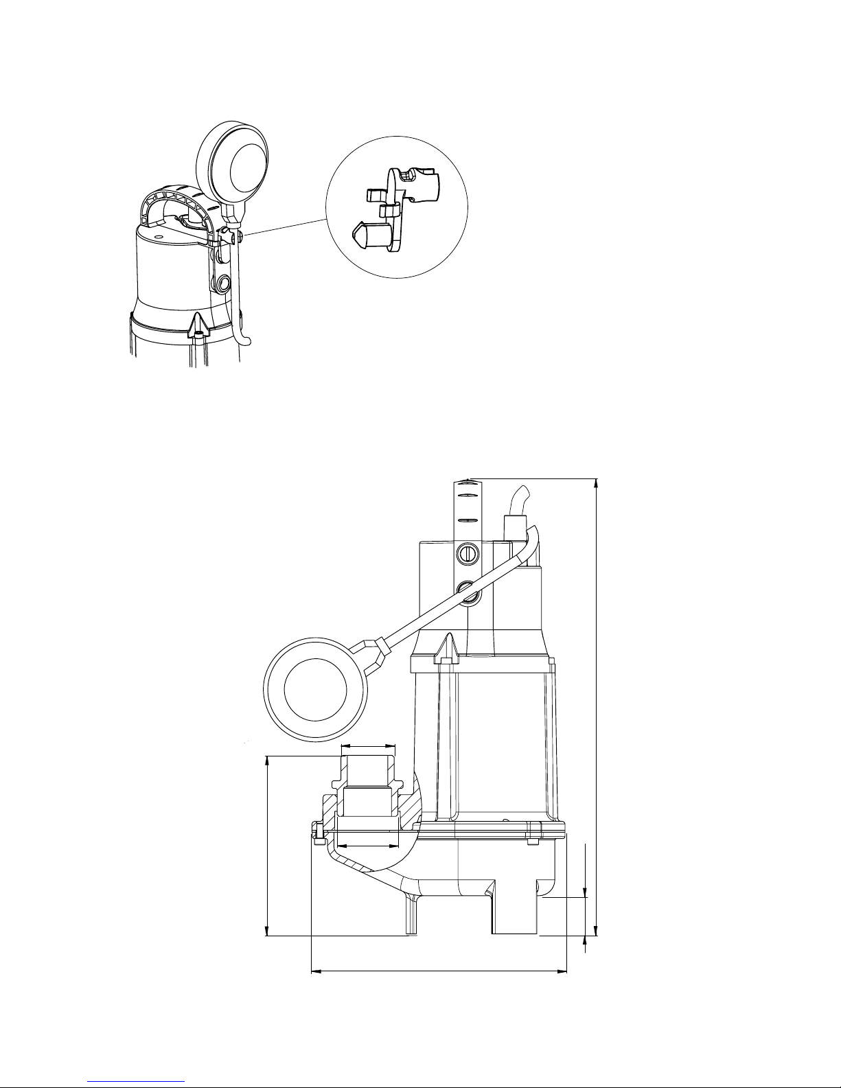
> Kabel ist werkseitig in Klemme unterhalb des Tragegriffes befestigt. (siehe Seite
13, Abbildung 3)
> Ein- und Ausschaltniveau durch Veränderung des Abstandes (= der Kabel länge)
zwischen Klemme und Schwimmerschalter einstellen. Ausschaltniveau so bestimmen, dass die Pumpe nicht trocken laufen kann.
> Schwimmerschalter muss sich ungehindert bewegen können und darf den Boden
nicht berühren.
Für den Schaltanlagenbetrieb (Dauer an)
> Den im Lieferumfang enthaltenen Halter in die Öffnung oberhalb des Drehge-
lenks einklippsen. Dann Schwimmschalter in den Halter einklemmen, sodass der
Schwimmschalter nach oben zeigt. (siehe Seite 13, Abbildung 3). Pumpe schaltet
sich nicht selbständig aus und ist deshalb vor Trockenlauf zu schützen.
FLOWTP30 OS ohne Schwimmerschalter:
Für den Doppel-Schaltanlagenbetrieb (Dauer an).
Aufstellung/Einbau / Inbetriebnahme / Wartung
Page 11
11
9. Inbetriebnahme
Die automatische Niveausteuerung der Pumpe, FLOWTP30, schaltet sich ein, wenn das
eingestellte Einschaltniveau erreicht ist, und schaltet sich aus, wenn das eingestellte
Ausschaltniveau erreicht ist. Bei arretiertem Schwimmerschalter sowie bei der Pumpe
ohne Schwimmer,
FLOWTP30 OS, Schaltanlagenbetrieb (Dauer an) schaltet sich die Pumpe ein, sobald
die elektrische Versorgung hergestellt ist.
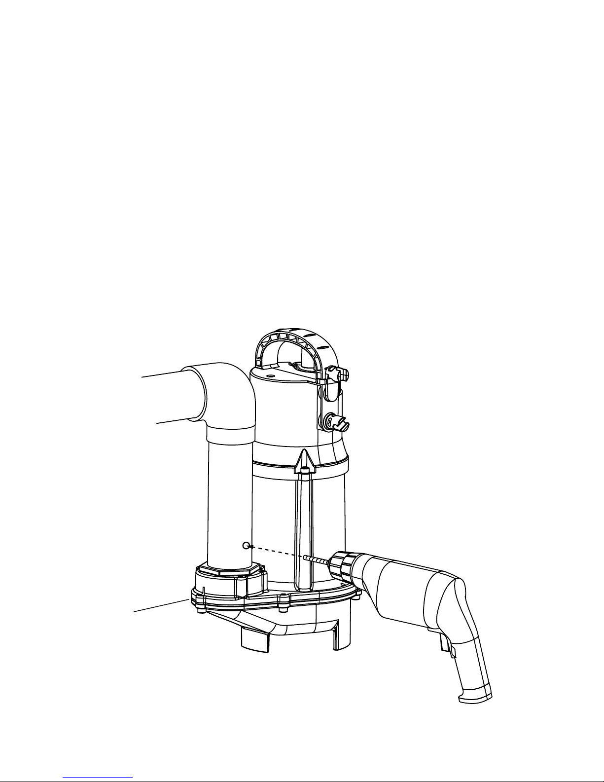
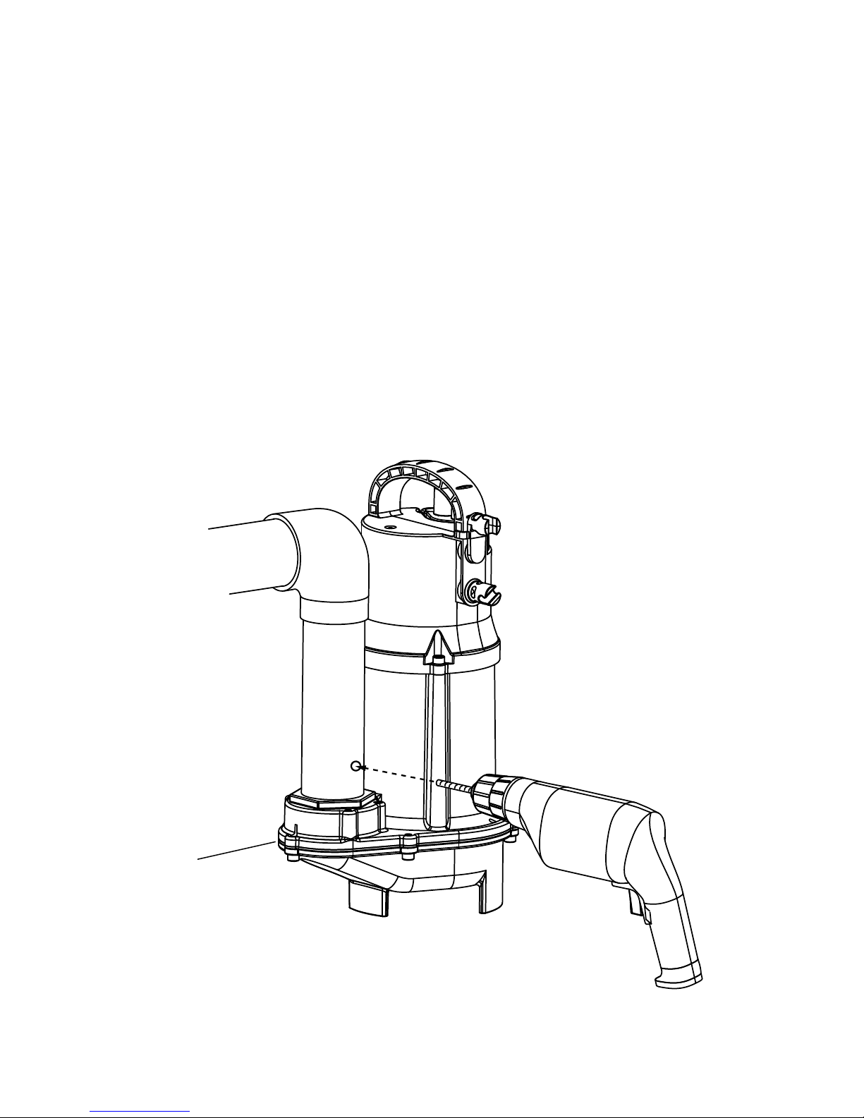
Das Entlüften der Pumpe kann auch durch eine Bohrung im Durchmesser von 3 mm
im Druckrohr wie in Abbildung 1 angegeben erreicht werden.
Hinweis:
Diese Bohrung ist beim Einbau der Pumpe in einem nicht abgedichteten Schacht (z.B.
Sicker-, Drainageschacht), d.h. überall dort wo die Kreiselkammer der Pumpe (a) nicht
ständig im Medium getaucht sein kann erforderlich.
Abbildung 1
(a)
Anhang
Page 12
12
10. Wartung
Vor jeder Arbeit: Pumpe vom elektrischen Netz trennen und gegen unbeabsichtigtes
Einschalten sichern. Druckleitung auf Beschädigungen prüfen.
Bei Problemen setzen Sie sich bitte mit Ihrem GC oder G.U.T. Partnerhaus in
Verbindung.
Wenn die Netzanschlussleitung dieses Gerätes beschädigt wird, muss sie durch den
Hersteller oder seinen Kundendienst oder eine ähnlich qualizierte Person ersetzt
werden, um Gefährdungen zu vermeiden.
11. Anhang
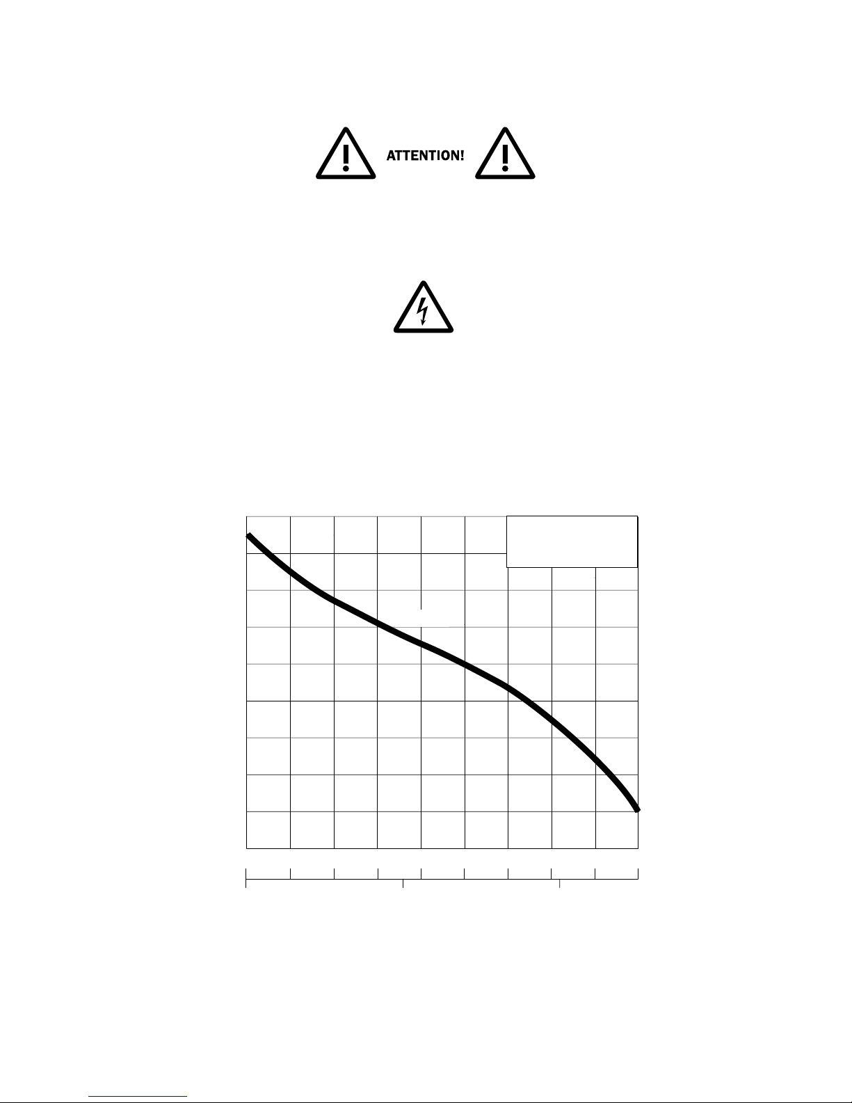
Abbildung 2
Kennlinie 50 Hz
2
0
0
1
2
3
4
5
6
7
8
9
2
4 6 8 10
4
41 6121
H
(m)
Q
(m3/h)
(l/s)
TP 30
H = Gesamtförderhöhe
Q = Förderstrom
Kennlinie nach ISO 9906
18
Page 13
13
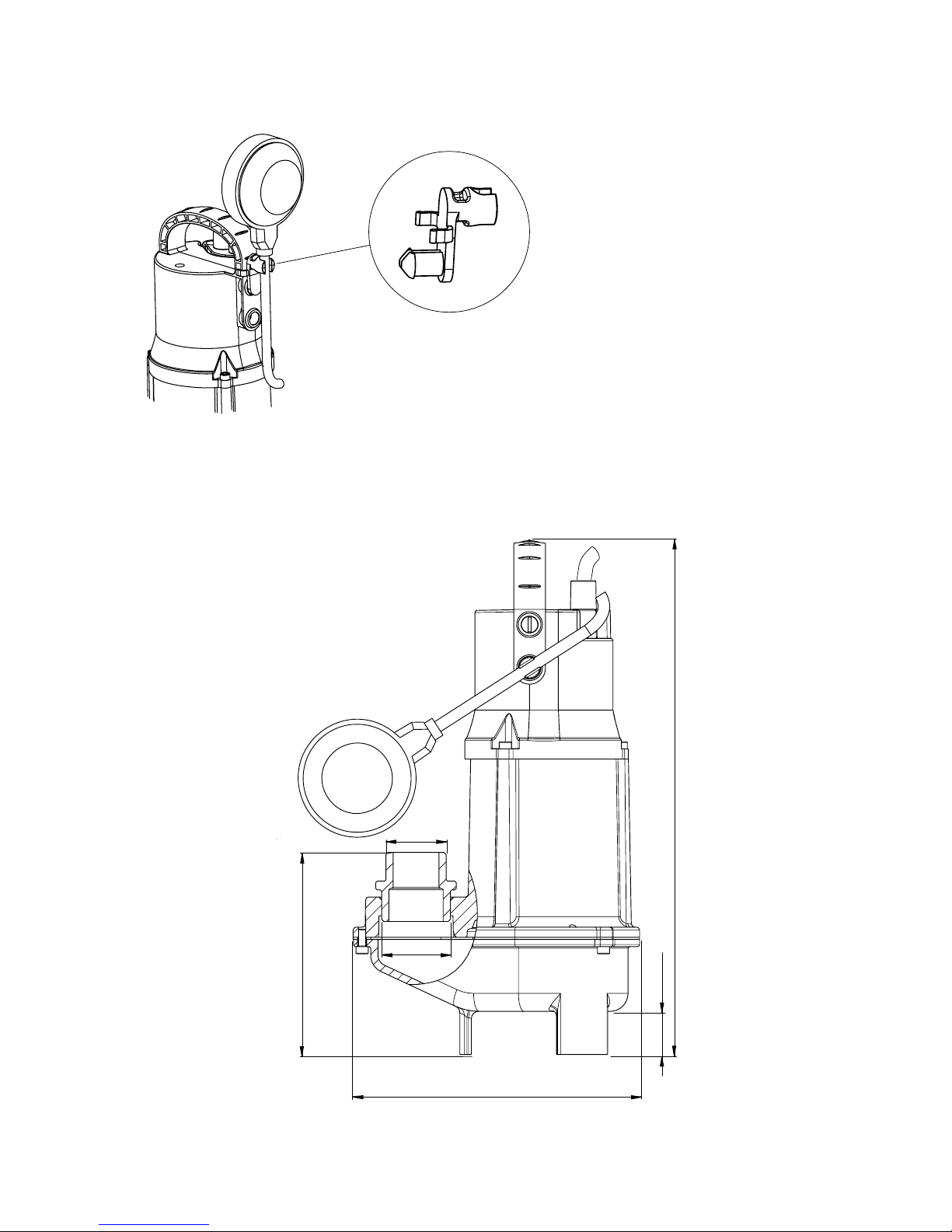
FLOWTP30 mit arretiertem Schwimmerschalter (für Schaltanlagenbetrieb)
Abbildung 3
Darstellung mit Adapter G 1¼" AG
Abbildung 4
Schaltanlagenbetrieb:
> Kann auf Wunsch bei Schalt-
anlagenbetrieb montiert
werden.
> Schwimmer - Befestigung für
Dauer an.
> Separates Teil, liegt lose bei.
199 mm
141 mm
30 mm
G1¼"
G1½"
357 mm
Page 14
14
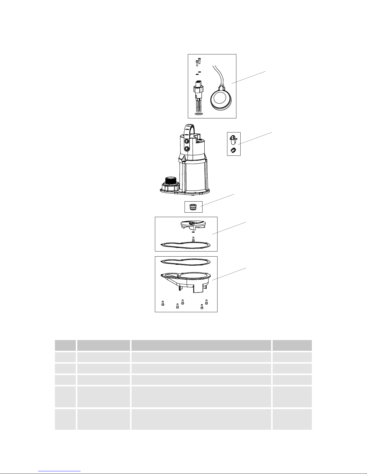
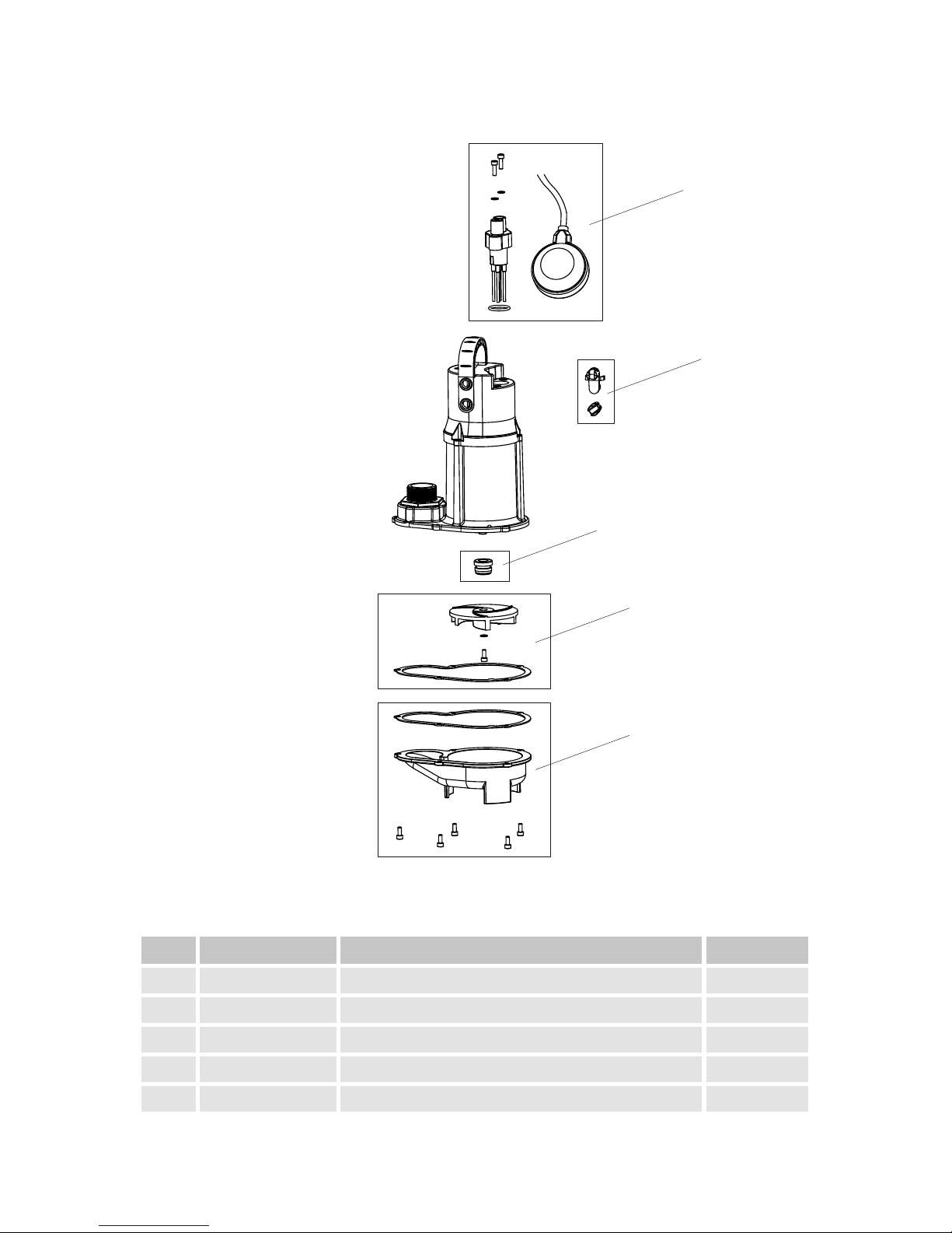
12. Ersatzteile
Abbildung 5
Pos. Artikelnr. Beschreibung Werksnr.
1 YAE62665459 FLOW EasyFit steckerfertige Kabelverbindung 62665459
2 YAE62665460 FLOW KS Befestigungsclip 62665460
3 YAE11110169 FLOW Gleitringdichtung 11110169
4 YAE62665461
FLOW Laufrad mit Kreiselkammer-Dichtung
und Befestigung
62665461
5 YAE62665462
FLOW Kreiselkammer mit Dichtung und
Befestigung
62665462
1
2
3
4
5
Page 15

15
Table of contents
EG Konformitätserklärung | EC Certicate of Conformity Page 2
DE FLOW Tauchpumpe 30 Page 3+
EN FLOW Submersible pump 30 Page 15
1. Safety Page 16
1.1 Identication of hints in the operating instructions Page 17
1.2 Carry out work in a safety conscious manner Page 18
1.3 Unilateral modication and spare parts manufacturing Page 18
1.4 Unproven usage Page 18
2. Scope of delivery Page 19
3. Application Page 19
4. Materials Page 19
5. Technical data Page 20
6. Transport Page 21
7. Electrical connection Page 21
8. Set-up/installation Page 22
9. Commissioning Page 23
10. Maintenance Page 24
11. Appendix Page 24 - 25
12. Spare parts Page 26
Safety / Identication of hints in the operating instructions
Page 16

16
1. Safety
Extracted from VDMA-Standard sheet 24292 (VDMA = Verband Deutscher Maschinenund Anlagenbau e.V.).
This unit can be used by children aged 8
years and above, and persons with reduced
physical, sensory, or mental capabilities,
or lack of experience and knowledge,
when they have been given supervision
or instruction concerning the safe use of
the device and understand the hazards
involved. Children must not play with the
appliance. Cleaning and user maintenance
should not be performed by children
without supervision.
These operating instructions contain basic information on installation, operating, and
maintenance, and should be followed carefully. For this reason it is essential that these
instructions are carefully read before installation or commissioning. The operating
instructions should always be readily available at the location of the unit.
In addition to following the safety regulations, it is also essential that the special safety
instructions given under other headings be observed.
Hints in the operating instructions / Carry out work in a safety conscious manner
Page 17

17
1.1 Identication of hints in the operating instructions
Safety instructions given in this operating manual, the non-observance of which
could cause danger to life have been specically highlighted with the general
danger symbol. (See DIN 4844-W 9).
The presence of a dangerous voltage is identied with the safety symbol. (See DIN
4844-W 8).
Symbols directly on the unit itself, e.g.
> Direction of rotation arrow
> Name plate
must be carefully observed and must be maintained in a legible condition.
Dangers which could arise due to non-observance of safety instructions
The non-observance of the safety instructions can lead to danger to personnel and also
to possible harm to the environment or the unit itself. Non-observance of
the safety instructions can invalidate the rights of the user to any compensation or
redress.
In detail, non-observance can for example result in the following dangers:
> Failure of important functions of the unit/installation.
> Danger to personnel by electrical, mechanical or chemical inuences.
> Danger to the environment by leakage of dangerous substances.
Work in a safety conscious manner / Modication and spare parts / Unproven usage
Page 18

18
1.2 Carry out work in a safety conscious manner
The safety instruction listed in this operating manual, the existing National Regulations
for safety, as well as any internal operating or safety regulations which apply in the
user‘s own premises must be observed.
Safety Regulations for the Owner/Operator
All dangers due to electricity must be avoided (for details consult the regulations of your
local Electricity Supply Company).
Safety Regulations for maintenance, inspection and installation work
The user of the unit should ensure that all maintenance, inspection or installation work
is carried out by authorised and qualied skilled personnel. The user must also make
certain that they have carefully studied the operating instructions. In principle all work
on the unit should only be carried out while it is stationary. Pumps or units used for
pumping of uids which could be injurious to health must be decontaminated.
After completion of the work, all safety and protective devices must be retted and
a check should be made that they are fully functional. Before starting up again, the
points listed in this operating instructions should be complied with.
1.3 Unilateral modication and spare parts manufacturing
Modications or changes to the unit/installation should only be carried out after
consultations with the manufacturer. Original spare parts and accessories authorised
by the manufacturer are essential for compliance with safety requirements. The use of
other parts can invalidate any claims for warranty or compensation.
1.4 Unproven usage
The operating safety of the unit is only guaranteed provided that the unit is used in
accordance with these operating instructions. The limit values given hereafter
should under no circumstance be exceeded. These operation instructions do not
supersede or exclude the following of generally valid regulations and standards.
Scope of delivery / Application / Materials
Page 19

19
2. Scope of delivery
KBN: FLOWTP30
Submersible pump, ready for plugging in, with 10 m cable and Schuko plug, built-in
adjustable oat switch, 1½" pressure outlet with female thread and 1¼" pressure
outlet with male thread.
KBN: FLOWTP30 OS
Submersible pump, ready for plugging in, for switchgear operation, with 10 m cable
and Schuko plug, 1½" pressure outlet with female thread and 1¼" pressure outlet with
male thread.
3. Application
> FLOW submersible pump 30 series is suitable for pumping clear water, rainwater,
domestic wastewater without faecal matter, and a solids content up to
0.5 % max. (maximum solids passage of diameter 30 mm).
> The pumps may not be used to pump corrosive, ammable, gaseous or potentially
explosive uids or sewage containing faecal matter. Fluids containing sand or other
abrasive substances reduce the service life of the pumps.
> The noise emission value is less than 70 dB (A).
> If damage can occur due to a failure of the pumping station, for example due to a
power failure or technical defect, an alternative system must be available as back-
up e. g. emergency power supply, double pumping station, network-independent
alarm, etc.
4. Materials
Materials
Pump housing EN-GJL-250
Impeller Polyamide
Seals NBR
Motor shaft Stainless steel 1.4057 (AISI 431)
Upper lid Polypropylene (PP)
Fasteners Stainless steel 1.4401 (AISI 316)
Technical data
Page 20

20
5. Technical data
Technical data
Article number FLOWTP30 & FLOWTP30 OS
Pressure outlet
> G 1½" female thread
> Adapter G 1¼" male thread
Max. ow (at 1 m) 18 m
3
/h
Max. head (at 0 m
3
/h) 8.5 m
Free passage 30 mm
Power cable (plug-in / EasyFit) H07RN-F 3G1.0
Mechanical seal Silicon carbide / carbon
Cable length 10 m
Weight Approx. 8.5 kg
Voltage/frequency 1 x 230 V/50 Hz
Current type Alternating current
Nominal current 3.6 A
Motor power P1 0.8 kW
Speed 2900 rpm
Motor protection Temperature monitor built into winding
Plug Schuko plug
Protection class IP 68
Motor insulation class B
Motor protection activation
temperature
120 °C
Maximum immersion depth 10 m
Fluid temperature Max. 40 °C (60 °C for 5 minutes)
Pump curve – see page 24, gure 2, Dimensions – see page 25, gure 4
Transport / Electrical connection/ Set-up/installation
Page 21

21
6. Transport
Carry the pump by the carrying handle only, not by the electrical connecting cable or
oat switch. Do not bump or drop it. When lowering the pump into deep sumps or pits
use a rope or chain.
7. Electrical connection
> Observe the correct operating voltage (see “Technical data“).
> Never place the power plug in the water.
> Connect the pump to properly installed sockets (in compliance with VDE and
power-supply company regulations) protected by at least 10 A (slow-blowing) fuses.
For submersible pumps of protection class I, all exposed conductive parts are
connected to the protective earth conductor. Before the pump is put into operation,
an electrically skilled person must check that the protective earth cable is properly
connected.
> When operating pumps of protection class I, the following applies according to IEC
335-2-41:1984, Amendment 1:1990: Pumps of protection class I intended for use
in swimming pools or garden ponds must be equipped with a residual-current device (max. 30 mA) in the supply line. The pump may not be operated if any persons
are in the pool.
> Temperatures higher than those permitted cause the pump to be shut off by the
temperature monitor. After the temperature monitor is triggered, disconnect the
pump from the electrical system before correcting the cause of the fault, as otherwise it will switch on automatically once cooled down.
Commissioning
Page 22

22
8. Set-up/installation
For portable set-up:
Set up the pump on solid ground. When setting up in muddy or sandy ground the pump
should be operated while suspended in the medium, by a rope or chain, or placed on a
large baseplate. Do not suspend the pump by the cable.
For xed installation:
Install the pump in compliance with DIN EN 12056-4 regulations (e.g. route the
discharge line with a loop above the locally dened backow level).
FLOWTP30 with oat switch:
For automatic cut-in/cut-out:
> The cable is attached to the swivel clip at the end of the carrying handle.
> Adjust the cut-in and cut-out level by varying the distance (the cable length) bet-
ween the swivel clip and the oat switch. Dene the cut-out level so that the pump
cannot run dry.
> The oat switch must be able to move without any hinderances and must not touch
the ground.
For control panel operation (Always-on):
> Fit the “Always-on” clip (supplied as standard) by pressing it into the hole at the end
of the carrying handle above the swivel clip. Lock the oat switch in the clip so that
it always points upwards (see page 25, gure 3).
> The pump does not cut out and must be automatically protected from running dry.
FLOWTP30 OS without oat switch:
For double switching operation (Always-on).
Maintenance / Appendix
Page 23
23
9. Commissioning
The automatic level control of the FLOWTP30 pump switches on when the set cut-in
level has been reached and switches off at the set cut-out level. When the oat switch
is locked (control panel “Always-on“), the pump switches on as soon as the electrical
supply has been connected.
FLOWTP30 OS switches on automatically as the electrical supply is connected.
If an airlock occurs in the pump it can be vented by drilling a Ø 3 mm hole in the
pressure pipe before the non return valve where indicated in gure 1.
Note:
This is necessary in installations such as drainage wells where the minimum required
continuous immersion of the pump in the medium can not be constantly guaranteed
i.e. the level of the medium may fall naturally below the top of the volute (a).
Figure 1
(a)
Appendix
Page 24
24
10. Maintenance
Before carrying out any work, disconnect the pump from the electrical system and
secure it from being accidentally switched on again. Check the discharge pipeline for
damage. If there are problems, please contact your GC and G.U.T. partner.
To avoid danger if the power cable is damaged, it must be replaced by the
manufacturer or its service agent or a similarly qualied person.
11. Appendix
Figure 2
Pump Curve 50 Hz
2
0
0
1
2
3
4
5
6
7
8
9
2
4 6 8 10
4
41 6121
H
(m)
Q
(m3/h)
(l/s)
TP 30
18
H = total head
Q = discharge volume
Curve to ISO 9906
Page 25
25
FLOWTP30 with locked oat switch (control panel always-on operation)
Figure 3
Illustration with G 1¼" male thread adapter
Figure 4
Control panel always-on:
> Float switch mounting for
always-on operation.
> Can be easily tted when
required.
> “Always-on” clip supplied as
standard.
199 mm
141 mm
30 mm
G1¼"
G1½"
357 mm
Page 26
26
12. Spare parts
Figure 5
Pos. Item no. Description Factory no.
1 YAE62665459 FLOW EasyFit plug-in cable connection 62665459
2 YAE62665460 FLOW KS bracket 62665460
3 YAE11110169 FLOW Mechanical seal 11110169
4 YAE62665461 FLOW Impeller with volute seal and fasteners 62665461
5 YAE62665462 FLOW Volute with seal and fasteners 62665462
1
2
3
4
5
Page 27

27
Impressum
Montage- und Betriebsanleitung FLOW
© CONEL GmbH, Margot-Kalinke-Str. 9, 80939 München, Tel. +49 89 31 86 87 80
FLOWTP30/1.3/02-18
Sämtliche Bild-, Maß- und Ausführungsangaben entsprechen dem Tag der Drucklegung.
Änderungen, die dem technischen Fortschritt und der Weiterentwicklung dienen,
behalten wir uns vor.
Modell- und Produktansprüche können nicht geltend gemacht werden.
Gültig für: EU-Länder und Schweiz, nicht für UK.
Imprint
FLOW Installation and Operating Instructions
© CONEL GmbH, Margot Kalinke-Str. 9, 80939 München, Phone: +49 89 31 86 87 80
FLOWTP30/1.3/02-18
All illustrations, dimensions, technical data and product information are
correct at time of printing.
We reserve the right to make changes in the interest of technical
progress and development.
Claims arising from product redesign or modification will not be upheld.
Valid for: EU countries excluding UK, and for Switzerland.
Page 28

„Mit innovativen Systemen schaffen wir
effiziente Lösungen für das professionelle Handwerk.“
Alles aus einer Hand:
VIS Vorwand-Installations-System
Vormontier te Elemente | Schienen-Befestigungssystem | Barrierefrei
CONNECT Rohrinstallation, Fittingsysteme
Presssystem | Stecksystem | Mehrschicht-Verbundrohre
FLEX Isolierungen
Kälte | Wärme | Solar
FLAM Brandschutz
Abschottung | Manschetten | Tape | Kitt | Mörtel
CLIC Befestigungs- und Montagesysteme
Rohrschellen | Montageschienen
CLEAR Wasseraufbereitung
Filtration | Enthärtung
FLOW Mobile Pumpen
Tauchpumpe | Hebeanlagen
CARE Chemiewirkstoffe
Reinigen – Pflegen – Warten | Mitnahme-Sortiment
Regal | Etikett | Barcode | Karton
EASYSTORE Lagermanagement-System
TOOLS Werkzeuge, Arbeitsmittel
Trennscheiben | Werkzeugkoffer
 Loading...