

Page 1
FLOW
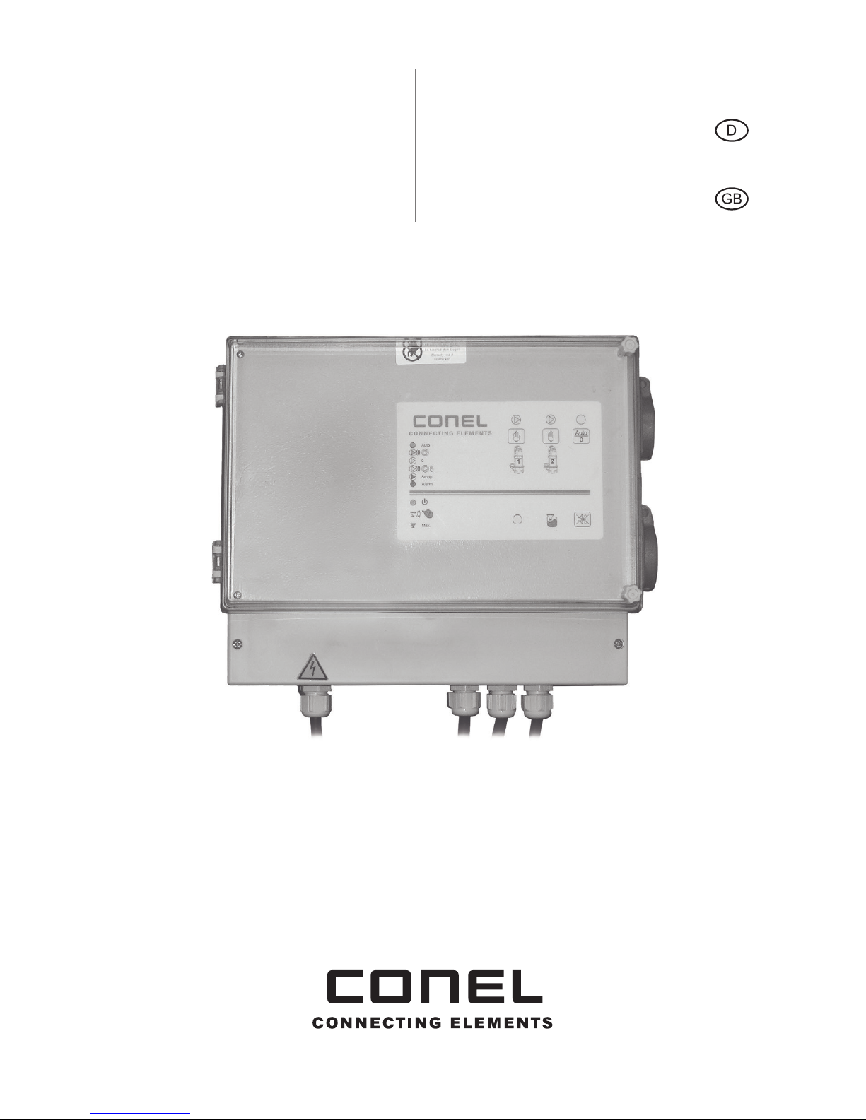
Schaltkasten FLOWSA mit Schwimmerschalter für Doppelpumpstationen
Betriebsanleitung
Control box FLOWSA with oat switches
for double pumping station
Operating instructions
Page 2

Inhalt
1. EU Konformitätserklärung Seite 3
2. Allgemeine Hinweise S. 4
3. Zutreffende EG-Richtlinien S. 4
4. Garantiesiegel und Typenschild S. 5
5. Steuerung für 2 Tauchpumpen FLOWTP30 (Wechselstrom) S. 5
6. Gehäuse S. 6
7. Grundausstattung S. 7
8. Anschluss kundenseite S. 8
9. Montage S. 9
10. Inbetriebnahme S. 10 - 11
11. Funktionsbeschreibung Niveausteuerung S. 11
12. Inbetriebnahme S. 12
13. Meldeleuchten S. 13
14. Bedienvorgänge (Service) S. 14
15. Installationsbeispiel S. 15
Impressum S. 31
English version page 16 +
2
Page 3

Wir, die
erklären in alleiniger Verantwortung,
dass das Produkt
auf das sich diese Erklärung bezieht,
den einschlägigen grundlegenden
Sicherheits- und Gesundheitsanforde-
rungen der EU-Richtlinien entspricht:
Angewendete harmonisierte
Normen, insbesondere:
München, 01. Oktober 2015
·
Unterschrift Geschäftsführer
We the
declare under our sole responsibility
that the product:
to which this certificate applies,
conforms to the basic health
and safety requirements
of EEC Directives:
Applied harmonized standards
in particular:
Munich, 01
October, 2015
Signature managing director
CONEL GmbH
Margot-Kalinke-Straße 9 · 80939 München
FLOWSA · KBN: FLOWSA
2014/35/EC · 2004/108/EC
EN 60730-1: 2012-10 · EN 61000-6-1: 2007 ·
EN 61000-6-2: 2005 / AC: 2005 · EN 61000-6-3: 2007 + A1: 2011
EU Konformitätserklärung | Certificate of Conformity
3
Page 4

2. Allgemeine Hinweise
Umbau oder Veränderungen an den Klemmengehäusen sind nicht gestattet.
Ausgenommen sind das Anbringen von zusätzlichen Kabel -und Leitungseinführungen
und das Montieren von Anschlussklemmen im Rahmen der Zulassung des
Betriebsmittels.
Die Steuerung ist bestimmungsgemäß in unbeschädigtem und einwandfreiem Zustand
zu betreiben.
Als Ersatzteile und zur Reparatur dürfen nur Originalteile verwendet werden.
Montage und Wartungsarbeiten dürfen nur von einer qualizierten Fachkraft in Übereinstimmung mit national geltenden Regeln durchgeführt werden.
Im Rahmen der Elektrostatik Verordnung sind geeignete Schutzmaßnahmen zu ergreifen (Erdung / Schutzleiteranschluss).
Hinweis!
Fehlerhafter oder unzulässiger Einsatz sowie das Nichtbeachten der Angaben dieser
Betriebsanleitung schließen eine Gewährleistung aus.
3. Zutreffende EG-Richtlinien
EG – Niederspannungsrichtlinie 2014/35/EU
Elektromagnetische Verträglichkeit 2004/108/EG
Angewandte harmonisierte Normen:
> EN 61000-6-1:2007
> EN 61000-6-3:2007 +A1:2011
> EN 61010-1:2001 (VDE 0411-1:2002, IEC 61010-1:2002)
4
Allgemeine Hinweise | Zutreffende EG-Richtlinien
Page 5
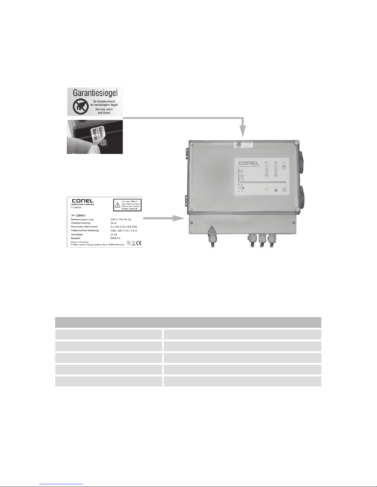
4. Garantiesiegel und Typenschild
Garantiesiegel
Sicherheitssiegel (Garantie)
Typenschild
5. Steuerung für 2 Tauchpumpen FLOWTP30 (Wechselstrom)
Mit 3 Schwimmschalter anschlussfertig
Technische Daten
Spannung 230 V Wechselstrom
Max. Vorsicherung 16 A
Nennstrom der Pumpen Voreingestellt auf 3,6 A (TP30 OS)
Pumpe 230 V Wechselstrom, 1-phasig
Störmeldeausgang Potentialfrei, max. 250 V~, max. 6,5 A
Zulässiger Anschluss von Conel Pumpen-Typen
2 Conel FLOW TP30 OS (230 V~ / 3,6 A / 0,8 kW)
Direktanschluss der Pumpen erfolgt über zwei seitliche Schuko-Steckdosen.
Bei Zuwiderhandlung oder Verwendung anderer Pumpen entfällt die Gewährleistung.
5
Garantiesiegel und Typenschild | Steuerung für 2 Tauchpumpen FLOWTP30
Page 6
6. Gehäuse
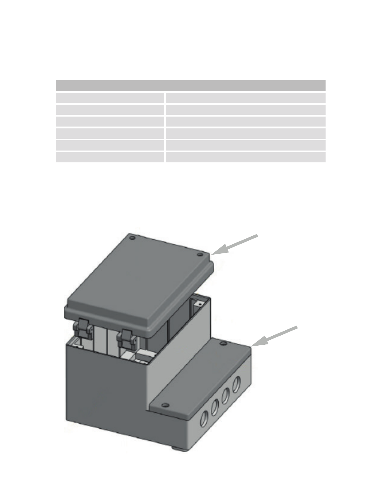
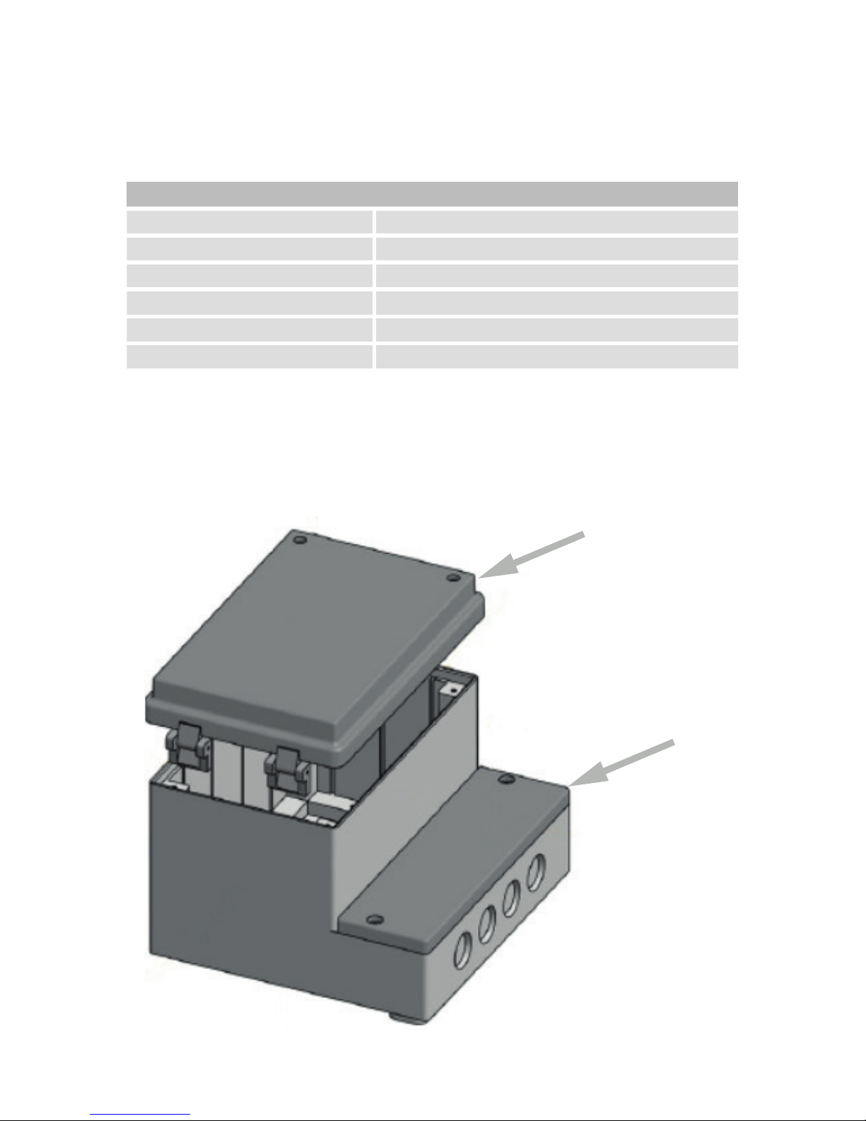
ISO-Gehäuse mit separatem Klemmenanschlussbereich mit eigener Abdeckung
Technische Daten
Material Kunststoff: ABS
Maße ( L x B x H ) 310 x 260 x 117 mm
Deckel Klarsichtdeckel mit Scharnier und Verschluss
Farbe Grundgehäuse RAL 7035
Farbe Deckel Rauchglas ähnlich
Schutzart IP 54
Das Gehäuse folgendermaßen Zweistug aufgebaut:
1. Bedien- und Meldeeinrichtungen hinter einem Glasdeckel von außen sichtbar.
2. Kundenseitiger elektrischer Anschlussraum.
1
2
6
Gehäuse
Page 7

7. Grundausstattung
Netzanschluss über Anschlusskabel mit Schuko-Netzstecker (1 m) Anschlussfertig
montiert.
> 3 Schwimmerschaltereingänge
> Interner Summer /Alarm (abschaltbar)
> Hand / Auto / 0
> Störmeldeausgang (Ruhestromprinzip, Potentialfrei) max. 250 V~ , max. 6,5 A
> Zwangsentleerung / Start nach 24 h Stillstands Zeit
> Wechselbetrieb nach jedem Pumpvorgang
> Netzausfallalarm akustisch und optisch (Akku erforderlich, Zubehör)
Das Gehäuse folgendermaßen Zweistug aufgebaut:
1. Netzspannung
2. Hand-Betrieb / Auto-Betrieb / 0 - pro Pumpe
3. Störung / Alarm
4. Hochwasser
5. Störung Schwimmschalter
7
Grundausstattung
Page 8
8. Anschluss Kundenseite
> Gummischlauchleitung 1 m; 1,5 mm² 3-adrig mit Schuko-Stecker zur
Stromversorgung
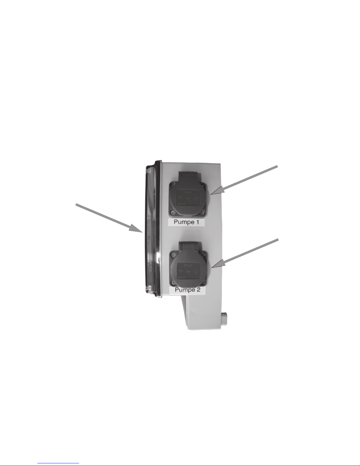
> Anschluss der Pumpen über 2 seitlich eingebaute Schuko- Steckdosen
> 2. Stufe Kundenseitigen Elektrischer Anschlussraum, nach der Demontage der
Abdeckung wird der Klemmenbereich sichtbar. In diesem Bereich sind zum
Anschluss der Schwimmschalter die gekennzeichneten Klemmen vorgesehen.
> Ein Anschlussschema bendet sich gut sichtbar auf der Innenseite der Abdeckung
> Kabeleinführungen sind beigefügte Würgenippel zu verwenden
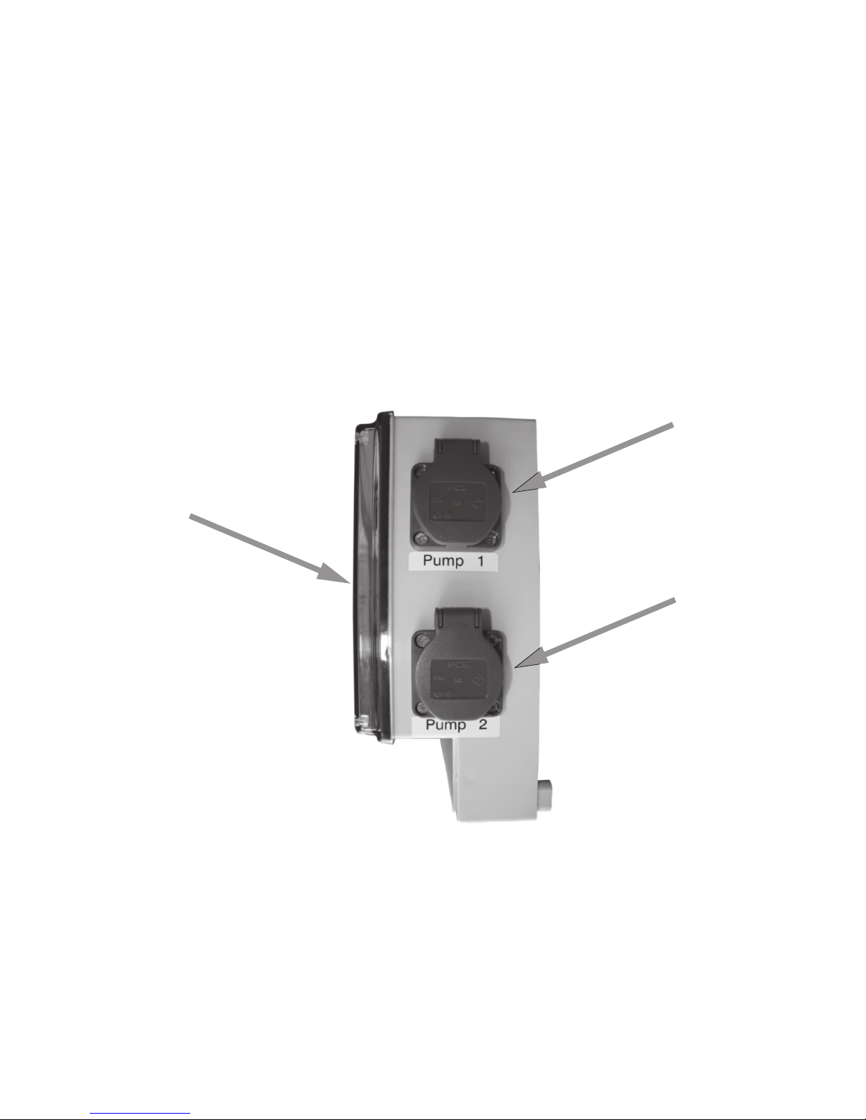
Seitenansicht
1. Schuko- Steckdosen für Pumpe 1
2. Schuko- Steckdosen für Pumpe 2
3. Transparente Abdeckung
Optionale Erweiterungen:
> Akku 9V Block für Netzausfallalarm KBN: ABSBATT9
1
2
3
8
Anschluss Kundenseite
Page 9
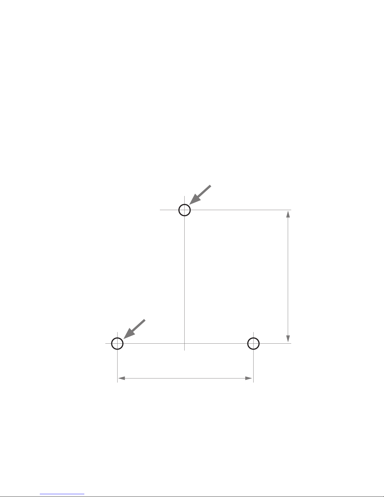
9. Montage
Beachten Sie die nationalen Sicherheits- und Unfallverhütungsvorschriften und die
nachfolgenden Sicherheitshinweise in der Betriebsanleitung.
Montageörtlichkeit ist ausschließlich im Innenbereich.
> Der Montageort muss stets gut zugänglich sein
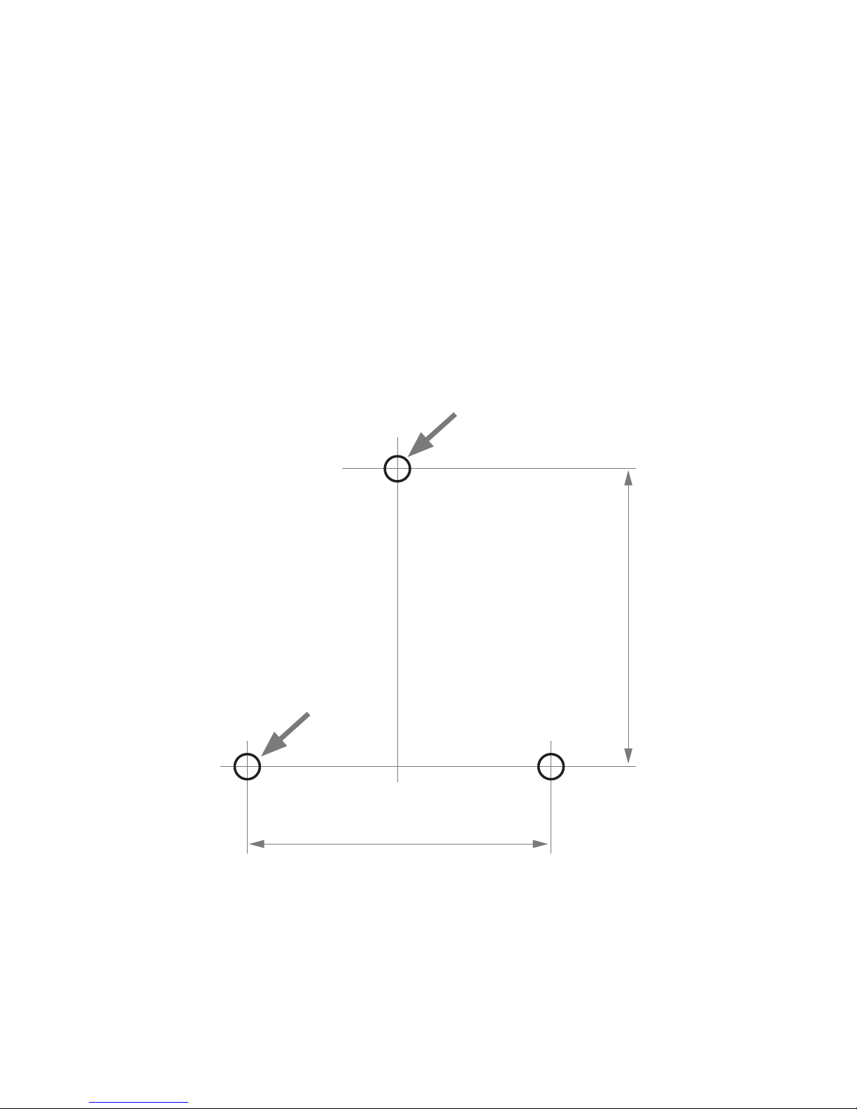
> Befestigung des Gehäuses am Bauträger mittels 3 Schrauben ausführen
> Der Untergrund muss fest, eben und frei von Schmutz sein Abstände zu Ecken,
Geräten oder anderen Einheiten usw. muss mindestens 5 cm sein (an der rechten
Seite bitte ca. 15 cm Abstand einhalten, um die Steckdosen zugänglich zu halten)
> Montagehöhe, gut bedienbar in circa 1,6 Meter Höhe
ø 7 mm
ø 6 mm
195 mm
280 mm
9
Montage
Page 10
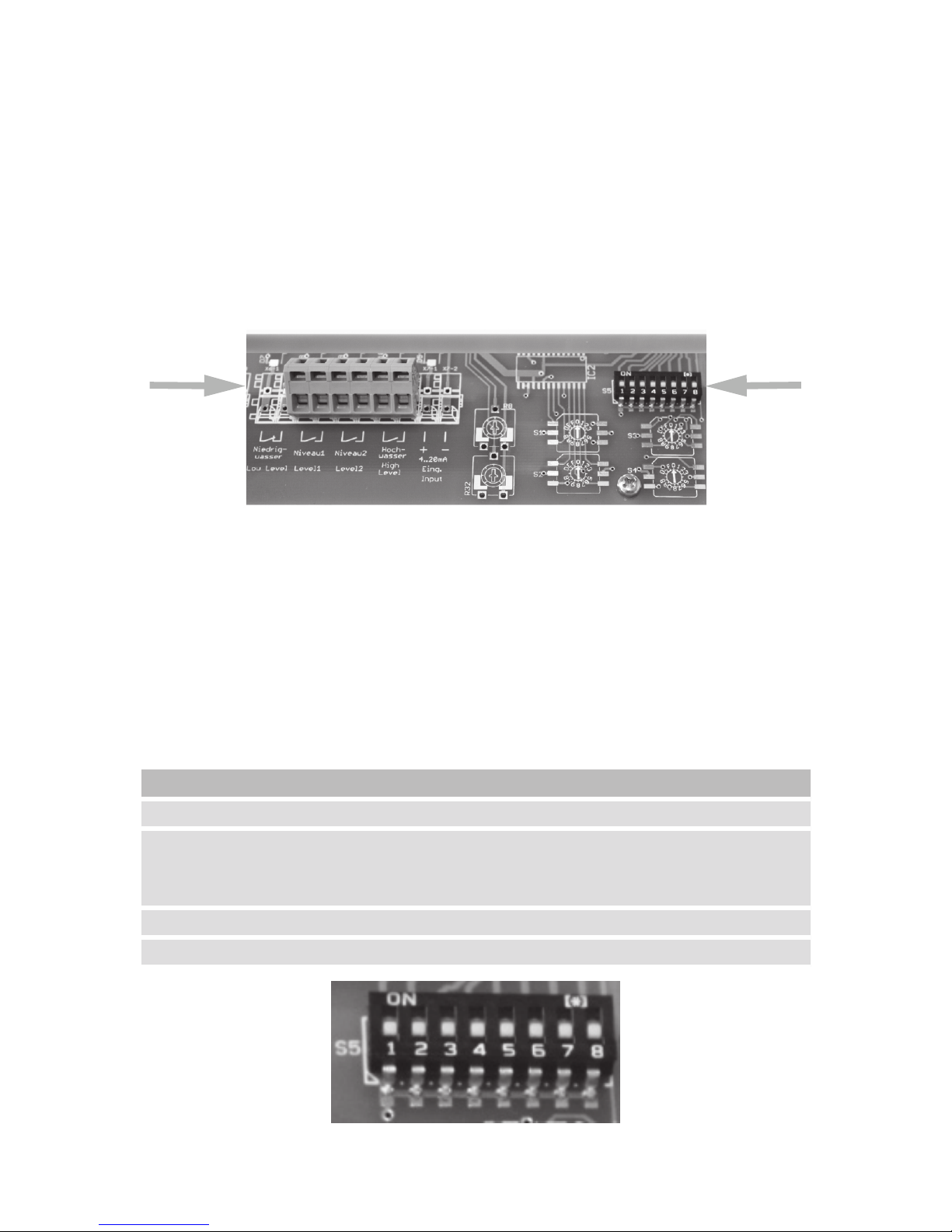
10. Inbetriebnahme
Nach der Montage der Pumpen im Pumpenschacht die Schuko-Stecker der Pumpen in
die dafür vorgesehenen Steckdosen einstecken.
ACHTUNG!
Vor dem Öffnen der unteren - Abdeckung vom elektrischer Anschlussraum Netzstecker
ziehen.
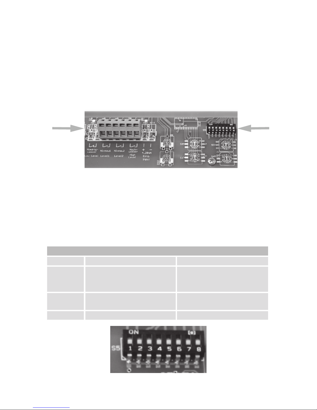
Schwimm
DIP-Schalter
-schalter
Die Anschlüsse der Schwimmschalter erfolgen im Klemmenkaste nach folgendem
Schema:
Niveau 1 = KS „C“ (Unten / AUS).
Niveau 2 = KS „B“ (Mitte / Ein).
Hochwasser = KS „A“ (Oben / Alarm)
Grundeinstellung DIP-Schalter: DIP–Schalter 1, 2, 3 in „Off“ Position
DIP-Schalter „Off“ „On“
1 Zwei Pumpen angeschlossen Eine Pumpe angeschlossen
2 Zwei Pumpen angeschlossen /
Parallelbetrieb beider Pumpen
möglich
Zwei Pumpen angeschlossen /
Einzelbetrieb kein Parallelbetrieb
möglich
3 Relais = Alarm, quittierbar Relais = Alarm , nicht quittierbar
4 - 8 Nicht belegt Nicht belegt
10
Inbetriebnahme
Page 11
HINWEIS!
Schalter ohne Funktion. Bitte in Stellung „Off“ lassen.
Anschluss des Störmeldeausgangs:
Ist der DIP-Schalter 3 auf „On“, zieht das Alarmrelais bei Hochwasser an. Eine externe
Alarmeinrichtung kann dann über die Klemmen X5-2 und X5-3 geschaltet werden.
ACHTUNG!
Schließen Sie die Abdeckung vom elektrischer Anschlussraum, bevor Sie den Netzstecker der Schaltanlage einstecken.
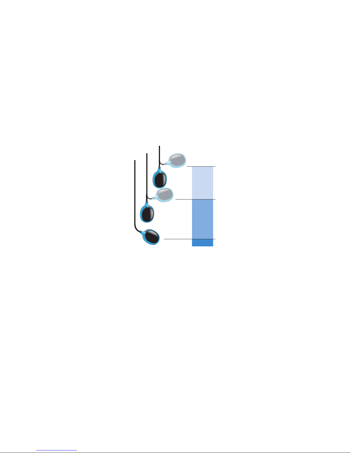
11 Funktionsbeschreibung Niveausteuerung
KS „C“ (unten)
steigt hoch
keine Funktion - Pumpenbereitschaft /
Trockenlaufschutz
Wichtiger Hinweis:
KS „C“ muss hoch steigen damit für
KS „B“ der Pumpenstart automatisch
freigeschaltet werden kann.
KS „B“ (Mitte)
steigt hoch
Pumpe 1 schaltet ein
HINWEIS:
Bei Bedarf kann eine Einschaltverzögerung von 15 Sekunden für Pumpe 2
(DIP-Schalter 2 „off“) aktiviert werden.
Pumpe 2 schaltet ein
KS „A“ (oben)
steigt hoch
Alarm wird ausgelöst
KS „A“ (oben)
geht runter
Alarm wird ausgeschaltet
KS „B“ (Mitte)
geht runter
keine Funktion
KS „C“ (unten)
geht runter
schaltet Pumpe(n) aus
A
B
C
11
Inbetriebnahme |Funktionsbeschreibung Niveausteuerung
Page 12
12. Inbetriebnahme
Handbetrieb Manueller Start von Pumpe 1 oder Pumpe 2
Durch kurzes betätigen der Taste Manuell wird
automatisch bis zum Ausschaltpunkt abgepumpt
Erneutes betätigen stoppt den Pumpvorgang.
ACHTUNG!
Voraussetzung für den manuellen Betrieb ist,
dass der unterste Schwimmschalter KS „C“
hoch gestiegen ist, siehe Funktionsbeschreibung
Niveausteuerung auf Seite 11.
Auto
0
Automatik /
Manuell
Pumpen zwischen Automatik und Manuellen
Betrieb umschalten.
HINWEIS:
Bei „manuell“ leuchten beide Anzeigeleuchten
für Pumpe 1 und Pumpe 2 gelb.
Nach 1 Minute ohne weitere Eingaben ertönt der
Alarmsummer um darauf aufmerksam zu
machen das keine der Pumpen betriebsbereit
ist.
Summer aus Summer ausschalten, Störmeldung quittieren.
12
Inbetriebnahme
Page 13
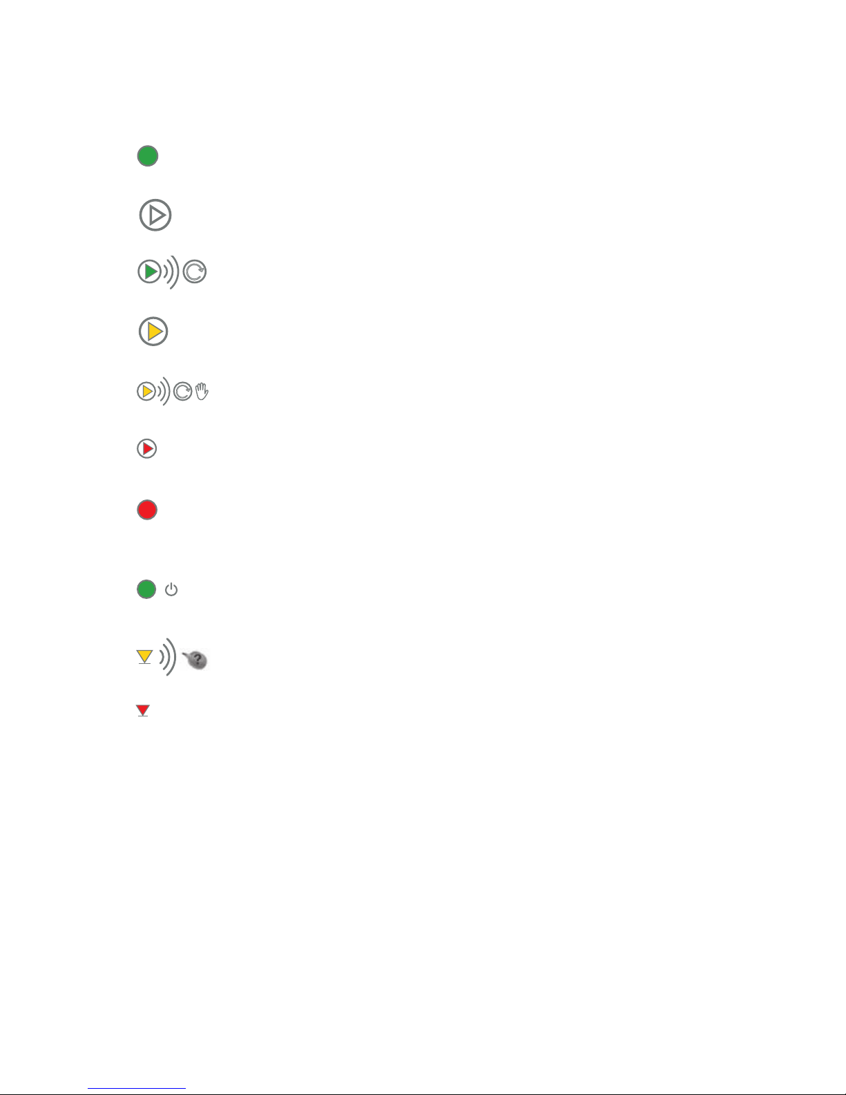
13. Meldeleuchten
Auto
Leuchtet grün Anlage ist im Automatik-Modus
Aus Pumpe steht, im Automatikbetrieb
Blinkt grün Pumpe läuft im Automatikbetrieb
0
Leuchtet gelb Pumpe aus, nur manueller Betrieb möglich
Blinkt gelb Pumpe läuft, im manuellen Betrieb
Stopp
Leuchtet rot Pumpe / Störung
Alarm
Leuchtet rot Es liegen eine oder mehrere Störungen vor,
diese wurde(n) bereits quittiert
Leuchtet grün Netzspannung vorhanden
Blinkt gelb Aktuelle Störung Schwimmer
(Falsche Schaltreihenfolge, siehe Seite 11)
Max.
Leuchtet rot Hochwasser
13
Meldeleuchten
Page 14
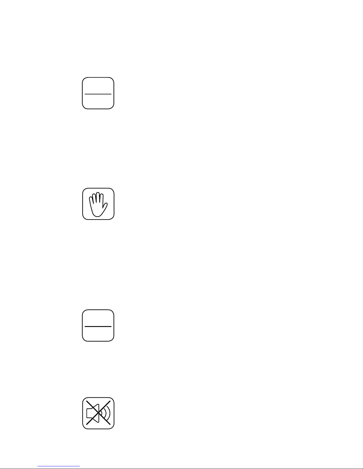
14. Bedienvorgänge (Service)
Beide Pumpen auf manuellen Betrieb umschalten:
Taste
Auto
0
betätigen
Beide Anzeigeleuchten für Pumpe 1 und Pumpe 2 leuchten gelb.
HINWEIS:
Nach 1 Minute ohne weitere Eingaben ertönt der Alarmsummer um darauf
aufmerksam zu machen das keine der Pumpen betriebsbereit ist.
Pumpen im Handbetrieb einschalten:
Taste
für Pumpe 1, Pumpe 2 oder beide Pumpen drücken.
Die Pumpen laufen nur bis zum Mindestwasserstand (Trockenlaufschutz).
ACHTUNG!
Voraussetzung für den manuellen Betrieb ist, dass der unterste Schwimmschalter KS
„C“ hoch gestiegen ist, siehe Funktionsbeschreibung Niveausteuerung auf Seite 11.
Beide Pumpen auf Automatik schalten:
Taste
Auto
0
betätigen
Beide Anzeigeleuchten für Pumpe 1 und Pumpe 2 gehen aus.
Störung quittieren:
Taste
drücken
14
Bedienvorgänge (Service)
Page 15
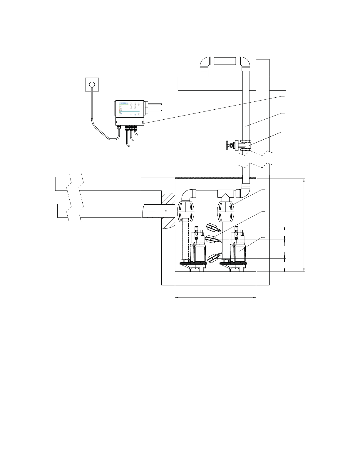
15 Installationsbeispiel
Legende
1 Absperrschieber 4 FLOWTP30 OS
2 Rückußverhinderer 5 Schwimmerschalter
3 Druckleitung 6 Schaltanlage FLOWSA
HINWEIS!
Vorschriften zum Anschluss der Abwasserleitung variieren von Land zu Land.
Informieren Sie sich über die Bestimmungen vor Ort.
Schachtgröße 600 x 600
Min. 110
Min. 150
Min. 110
Min 800
ALARM
EIN
AUS
2
4
5
1
3
6
Schwimmschalter Alarm:
Hochwasser
Pumpe
Pumpe
Schwimmschalter Aus:
Niveau 1
Schwimmschalter Ein:
Niveau 2
1
2
3
4
5
6
Schwimmschalter Alarm:
Hochwasser
1 Absperrschieber
2 Rückflußverhinderer
3 Druckleitung
4 FLOWTP30 OS
5 Schwimmerschalter
6 Schaltanlage FLOWSA
Pumpe
Pumpe
Schwimmschalter Aus:
Niveau 1
Schwimmschalter Ein:
Niveau 2
15
Installationsbeispiel
Page 16

Contents
1. EC Certicate of Conformity page 3
2. General information p. 17
3. Regulatory information - EC Directives p. 17
4. Warranty label and nameplate p. 18
5. Control for two submersible pumps FLOWTP30 (AC) S. 18
6. Casing S. 19
7. Basic equipment S. 20
8. Customer connection S. 21
9. Mounting S. 22
10. Commissioning S. 23 - 24
11. Level control switch settings S. 24
12. Service S. 25
13. Function indicator lights S. 26
14. Operations (Service) S. 27
15. Installation example S. 28
Impressum S. 31
16
Page 17

2. General information
Modications or alterations to the terminal housings are not permitted except for the
installation of additional cable and cable entries, and mounting of connection terminals
as part of the approval of the equipment.
The control unit must be operated as intended in an undamaged and faultless
condition.
Only original parts may be used as spare parts and for repair.
Installation and maintenance work may only be carried out by a qualied specialist in
accordance with national rules.
Appropriate protective measures must be taken within the framework of the
electrostatic regulation (earthing /protective conductor connection).
NOTE!
Incorrect or unauthorized use, as well as failure to observe the instructions in this
manual, shall result in the loss of warranty.
3. Regulatory information - EC Directives
Low Voltage Directive 2014/35 / EU
Electromagnetic compatibility 2004/108 / EC
Applied harmonized standards:
> EN 61000-6-1:2007
> EN 61000-6-3:2007 +A1:2011
> EN 61010-1:2001 (VDE 0411-1:2002, IEC 61010-1:2002)
17
General information | Regulatory information
Page 18
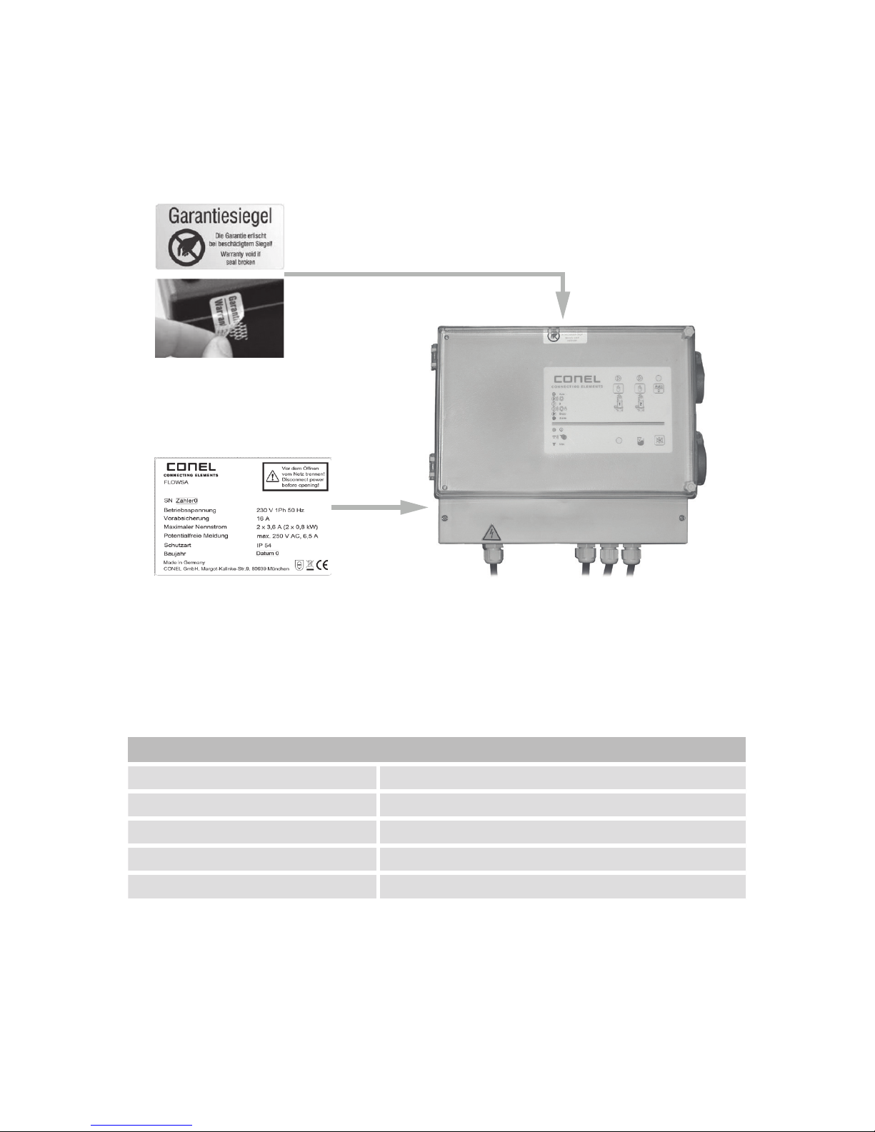
4. Warranty label and nameplate
Warranty label
Security label (guarantee)
Nameplate
5. Control for two submersible pumps FLOWTP30 (AC)
Wired ready for connection of three oat switches
Technical data
Voltage 230 V AC (alternating current)
Max. fuse 16 A
Rated current (for pumps) Pre-set to 3.6 A (TP30 OS)
Pump 230 V AC (single phase)
Fault message output Potential-free, max. 250 V~, max. 6.5 A
Permitted connection of CONEL pump types
Two Conel FLOW TP30 OS (230 V~ / 3.6 A / 0.8 kW)
Direct connection of the pumps is via two side plug sockets.
In the event of an infringement or the use of other pumps, the warranty will be void.
18
Warranty label and nameplate | Control for two submersible pumps
Page 19
6. Casing
ISO housing, featuring separate terminal with its own cover
Technical data
Material Plastic: ABS
Dimensions ( L x B x H ) 310 x 260 x 117 mm
Cover Transparent lid with hinge and lock
Color of basic housing RAL 7035
Colour of cover Similar to smoked glass
Protection class IP 54
The housing has a two-stage construction as follows:
1. Operating and signaling devices visible from the outside behind a glass lid.
2. Customized electrical connection compartment.
1
2
19
Casing
Page 20

7. Basic equipment
Ready for mains connection via connecting cable (1 m) with Schuko mains plug.
> Three oat switch inputs
> Internal buzzer / alarm (can be disabled)
> Hand / Auto / 0
> Fault signal output (retentive current principle, potential-free) max. 250 V~ , max.
6.5 A
> Forced emptying / start after 24 hour standstill time
> Change mode after each pumping process
> Power failure alarm, acoustic and visual (battery required as accessory)
Indicator lights for:
1. Power supply
2. Manual operation / auto-operation / 0ff (for each pump)
3. Fault / Alarm
4. High water
5. Float switch malfunction
20
Basic equipment
Page 21
8. Customer connection
> Metre long rubber cable; 1.5 mm², 3-wire with plug for connection to the power
supply.
> Two built-in schuko sockets at the side for connection of pumps.
> Level 2 electrical connection compartment. After removing the cover the terminal
area is visible. In this area the marked terminals are provided for the connection of
the three oat switches.
> A connection diagram is clearly visible on the inside of the cover.
> Self-sealing grommets enclosed for use as cable glands.
Side view
1. Schuko socket for Pump 1
2. Schuko socket for Pump 2
3. Transparent cover
Optional accessory:
> 9V battery block for power failure alarm. KBN: ABSBATT9
1
2
3
21
Customer connection
Page 22
9. Mounting
Note the national safety and accident prevention regulations and the following safety
instructions in the operating instruction manual.
Installation is strictly for indoor use only.
> The place of installation must always be accessible.
> Fasten the housing to the building beam using three screws.
> The surface must be xed, level, and free of dirt. Distance to corners, devices
or other units etc. must be at least 5 cm (on the right side please keep 15 cm
distance to keep the sockets accessible).
> Mount at a height of 1.6 meters for ease of operation.
ø 7 mm
ø 6 mm
195 mm
280 mm
22
Mounting
Page 23
10. Commissioning
After the installation of the pumps in the pump sump connect the Schuko plugs of the
pumps with the sockets provided for this purpose.
ATTENTION!
Before opening the cover of the electrical connection compartment, disconnect the
mains plug from the power supply.
DIP switch Float switch
Connect the oat switches to the terminal block as follows:
Level 1 = KS “C“ (Down / OFF).
Level 2 = KS “B“ (Middle / ON).
High water = KS “A“ (Top / ALARM)
Basic settings for the DIP switch: DIP switch 1, 2, 3 in “OFF“ position
DIP switch “OFF“ “ON“
1 Two pumps connected One pump connected
2 Two pumps connected / parallel
operation of both pumps
possible
Two pumps connected / single
operation - no parallel operation
possible
3 Relay = alarm acknowledgeable Relay = alarm cannot be
acknowledged
4 - 8 Not used Not used
23
Commissioning
Page 24
NOTE!
Please leave switch in “OFF“ position when not functioning.
Connection of the fault message output:
If the DIP switch 3 is set to “ON“, the alarm relay is activated during high water.
An external alarm device can then be switched via terminals X5-2 and X5-3.
ATTENTION!
Close the cover of the electrical connection compartment before connecting the mains
plug to the power supply.
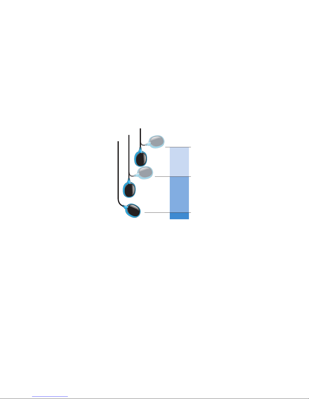
11 Level control switch settings
KS “C“ (bottom)
rises high
no function - pump readiness /
dry-running protection
Important note:
KS “C“ must be raised so that for
KS “B“ the pump start can be enabled
automatically.
KS “B“ (middle)
rises high
Pump 1 switches on
NOTE:
If necessary a switch-on delay of
15 seconds can be activated for
pump 2 (DIP switch 2 “OFF“).
Pump 2 switches on
KS “A“ (top)
rises high
alarm is triggered
KS “A“ (up)
goes down
alarm is switched off
KS “B“ (middle)
goes down
no function
KS “C“ (bottom)
goes down
turns off the pump (s
A
B
C
24
Commissioning | Level control switch settings
Page 25
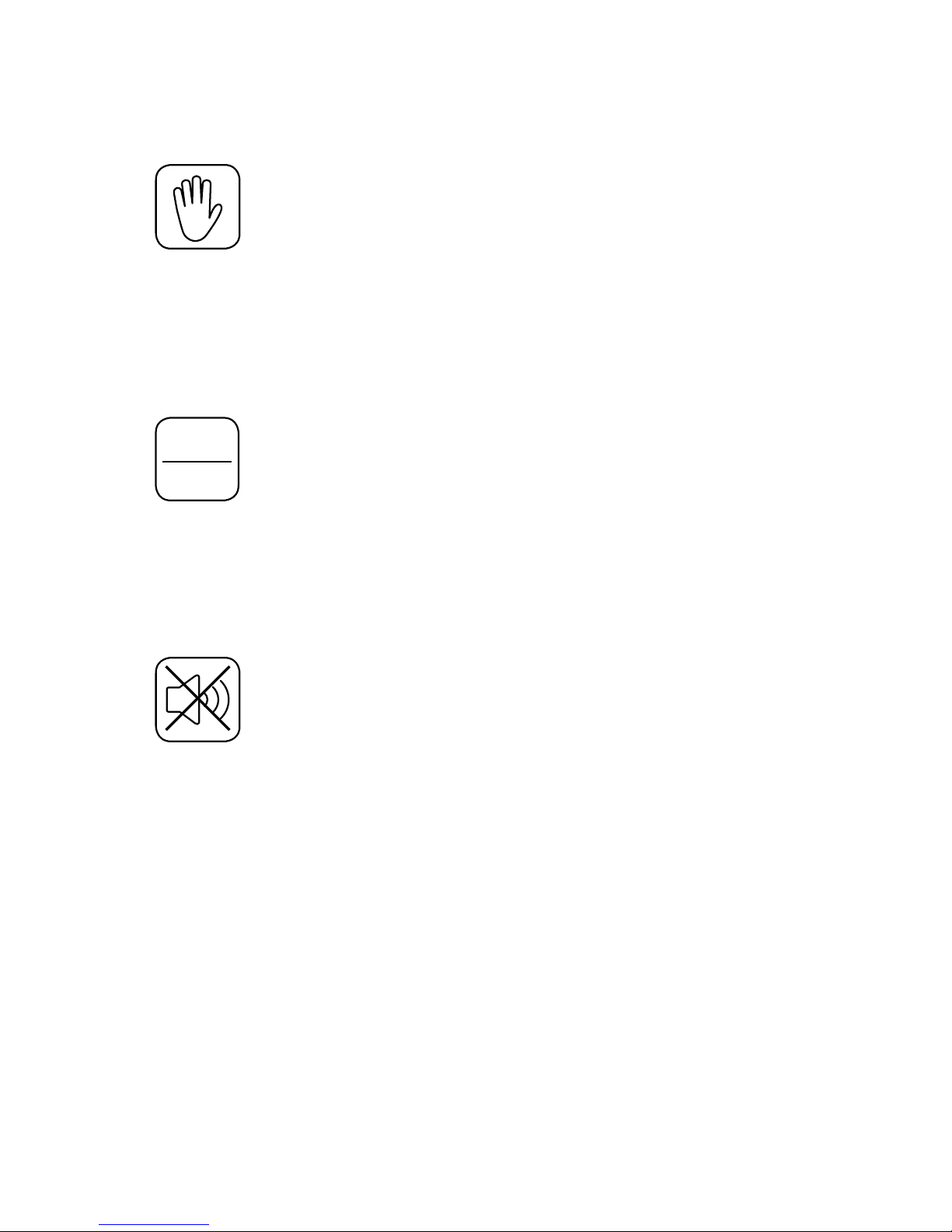
12. Service
Manual Manual start of pump 1 or pump 2.
Press the “Manual“ button briey - automatically
pumps down to the switch-off point.
Press again to stop pumping.
ATTENTION!
A prerequisite for manual operation is that the
lowest level switch KS “C“ has been raised, see
function description level control on page 24.
Auto
0
Automatic /
Manual
Switch the pumps between automatic and
manual mode.
NOTE!
If “Manual“ is selected, both indicator lights for
pump 1 and pump 2 light up yellow.
After one minute without further input the alarm
will sound to make sure that none of the pumps
are ready for operation.
Buzzer off Switch off the buzzer, acknowledge fault
message.
25
Service
Page 26
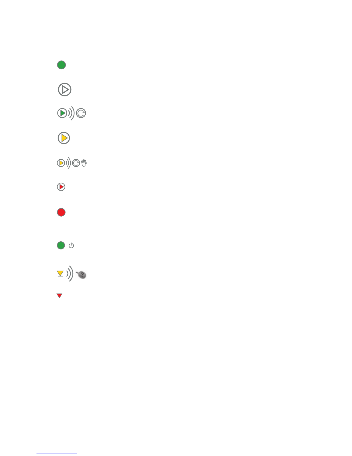
13. Function indicator lights
Auto
Lights green System is in automatic mode
Out Pump is in automatic mode
Lights green Pump runs in automatic mode
0
Lights yellow Pump off, only manual operation possible
Flashes yellow Pump running, in manual operation
Stopp
Lights red Pump / malfunction
Alarm
Lights red There are one or more disturbances,
these have already been acknowledged
Lights green Mains voltage available
Flashes yellow Current fault with oat switches
(incorrect sequence, see page 24)
Max.
Lights red High water
26
Function indicator lights
Page 27
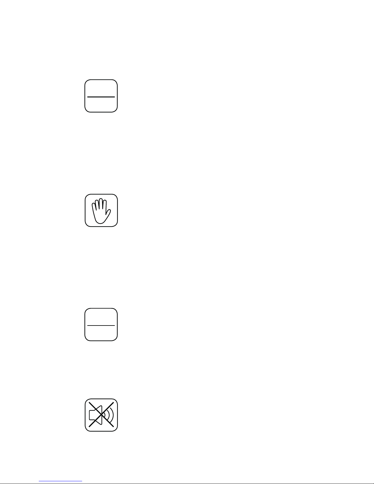
14. Operations (Service)
Switch both pumps to manual mode:
Press
Auto
0
button
Both indicator lights for pump 1 and pump 2 light up yellow.
NOTE!
After one minute without further input the alarm will sound to make sure that none of
the pumps are ready for operation.
Switch on pumps in manual mode:
Press
button for pump 1, pump 2 or both pumps
The pumps run only to the minimum water level (dry running protection).
ATTENTION!
A prerequisite for manual operation is that the lowest level switch KS “C“ has been
raised, see function description level control on page 24.
Switch both pumps on automatic (automatic operation):
Press
Auto
0
button
Both indicator lights for pump 1 and pump 2 are off.
Troubleshooting:
Press
button
27
Operations (Service)
Page 28
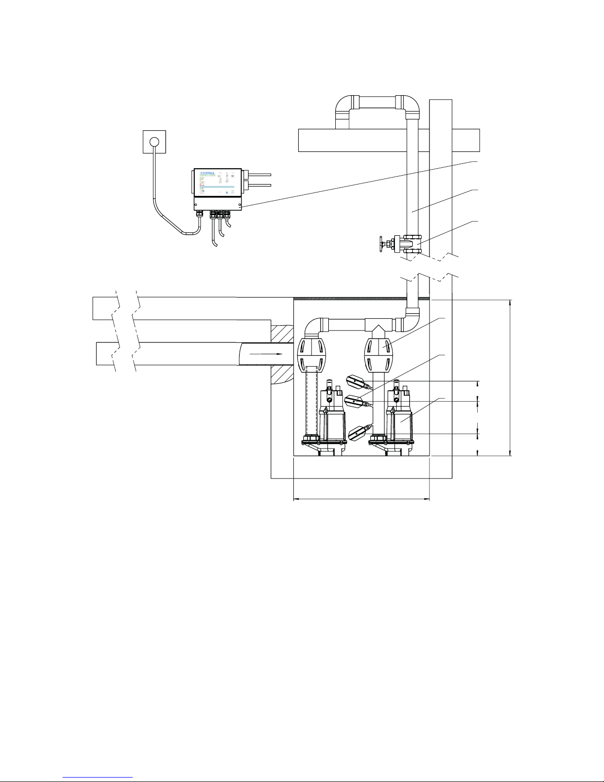
15 Installation example
Legend
1 Gate valve 4 FLOWTP30 OS
2 Check valve 5 Float switch
3 Pressure pipework 6 FLOWSA control box
NOTE!
Regulations for the connection of the wastewater pipeline vary from country to country.
Find out more about your local regulations.
Pump sump dimensions 600 x 600
Min. 110
Min. 150
Min. 110
Min 800
ALARM
ON
OFF
2
4
5
1
3
6
Float switch alarm:
High water
Pump
Pump
Float switch off:
Level 1
Float switch on:
Level 2
1
2
3
4
5
6
Schwimmschalter Alarm:
Hochwasser
1 Absperrschieber
2 Rückflußverhinderer
3 Druckleitung
4 FLOWTP30 OS
5 Schwimmerschalter
6 Schaltanlage FLOWSA
Pumpe
Pumpe
Schwimmschalter Aus:
Niveau 1
Schwimmschalter Ein:
Niveau 2
28
Installation example
Page 29

29
Page 30

30
Page 31

Impressum
Montage- und Betriebsanleitung FLOWSA
© CONEL GmbH, Margot-Kalinke-Str. 9, 80939 München, Tel. +49 89 31 86 87 80
FLOWSA/1.0/11-17
Sämtliche Bild-, Maß- und Ausführungsangaben entsprechen dem Tag der Drucklegung.
Änderungen, die dem technischen Fortschritt und der Weiterentwicklung dienen,
behalten wir uns vor.
Modell- und Produktansprüche können nicht geltend gemacht werden.
Gültig für: EU-Länder und Schweiz, nicht für UK.
Imprint
FLOWSA Installation and Operating Instructions
© CONEL GmbH, Margot Kalinke-Str. 9, 80939 München, Phone: +49 89 31 86 87 80
FLOWSA/1.0/11-17
All illustrations, dimensions, technical data and product information are
correct at time of printing.
We reserve the right to make changes in the interest of technical
progress and development.
Claims arising from product redesign or modification will not be upheld.
Valid for: EU countries excluding UK, and for Switzerland.
Impressum
31
Page 32

VIS Vorwand-Installationssystem
Vormontier te Elemente | Schienen-Befestigungssystem | Barrierefrei
CONNECT Rohrinstallation, Fittingsysteme
Presssystem | Stecksystem | Mehrschicht-Verbundrohre
FLEX Isolierungen
Kälte | Wärme | Solar
FLAM Brandschutz
Abschottung | Manschetten | Tape | Kitt | Mörtel
CLIC Befestigungs- und Montagesysteme
Rohrschellen | Montageschienen
EASYSTORE Lagermanagementsystem
Regal | Etikett | Barcode | Karton
TOOLS Werkzeuge, Arbeitsmittel
Trennscheiben | Werkzeugkoffer
CLEAR Wasseraufbereitung
Filtration | Enthärtung
FLOW Pumpen
mobile Tauchpumpen | Hebeanlagen
CARE Chemiewirkstoffe
Anwendungssysteme | Wartung | Reinigung | Instandhaltung | Baustof fe
CONEL – der beste Freund des Installateurs.
 Loading...