

Page 1
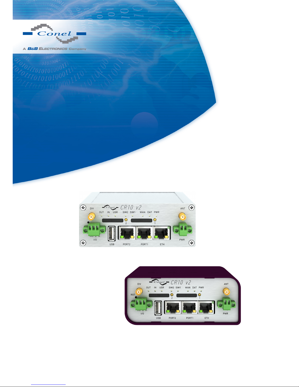
CDMA router CR10 v2
USER’S MANUAL
Page 2
USED SYMBOLS
Used symbols
Danger – important notice, which may have an influence on the user’s safety or the function
of the device.
Attention – notice on possible problems, which can arise in specific cases.
Information, notice – information, which contains useful advice or special interest.
GPL license
Source codes under GPL license are available free of charge by sending an email to:
Conel s.r.o., Sokolska 71, 562 04 Usti nad Orlici, Czech Republic
Manual issued in CZ, June 3, 2013
i
Page 3

CONTENTS
Contents
1 Safety instruction 1
2 Product disposal instructions 2
3 Router description 3
4 Contents of package 4
5 Router design 5
5.1 Router versions . . . . . . . . . . . . . . . . . . . . . . . . . . . . . . . . . . . . 5
5.2 Delivery identification . . . . . . . . . . . . . . . . . . . . . . . . . . . . . . . . 6
5.3 Version of firmware module . . . . . . . . . . . . . . . . . . . . . . . . . . . . . 7
5.4 Ordering codes . . . . . . . . . . . . . . . . . . . . . . . . . . . . . . . . . . . . 8
5.4.1 Basic version . . . . . . . . . . . . . . . . . . . . . . . . . . . . . . . . . 8
5.4.2 Full version . . . . . . . . . . . . . . . . . . . . . . . . . . . . . . . . . . 8
5.5 Basic dimensions of plastic box . . . . . . . . . . . . . . . . . . . . . . . . . . . 9
5.6 Basic dimensions of metal box . . . . . . . . . . . . . . . . . . . . . . . . . . . 9
5.7 Mechanical dimensions and mounting recommendations . . . . . . . . . . . . . 10
5.8 Removing from the DIN rail . . . . . . . . . . . . . . . . . . . . . . . . . . . . . 12
5.9 Description of the front panel . . . . . . . . . . . . . . . . . . . . . . . . . . . . 13
5.9.1 Status indication . . . . . . . . . . . . . . . . . . . . . . . . . . . . . . . 14
5.9.2 Power connector PWR . . . . . . . . . . . . . . . . . . . . . . . . . . . . 15
5.9.3 Antenna connector ANT, DIV (alternatively WIFI or WMBUS) . . . . . . 16
5.9.4 SIM card reader . . . . . . . . . . . . . . . . . . . . . . . . . . . . . . . 17
5.9.5 Ethernet port . . . . . . . . . . . . . . . . . . . . . . . . . . . . . . . . . 17
5.9.6 PORT1 . . . . . . . . . . . . . . . . . . . . . . . . . . . . . . . . . . . . 19
5.9.7 PORT2 . . . . . . . . . . . . . . . . . . . . . . . . . . . . . . . . . . . . 19
5.9.8 USB Port . . . . . . . . . . . . . . . . . . . . . . . . . . . . . . . . . . . 20
5.9.9 I/O Port . . . . . . . . . . . . . . . . . . . . . . . . . . . . . . . . . . . . 21
5.9.10 Reset . . . . . . . . . . . . . . . . . . . . . . . . . . . . . . . . . . . . . 23
6 First use 24
6.1 Connecting the router before first use . . . . . . . . . . . . . . . . . . . . . . . 24
6.2 Start . . . . . . . . . . . . . . . . . . . . . . . . . . . . . . . . . . . . . . . . . . 25
6.3 Configuration . . . . . . . . . . . . . . . . . . . . . . . . . . . . . . . . . . . . . 25
6.3.1 Configuration over web browser . . . . . . . . . . . . . . . . . . . . . . . 25
6.3.2 Configuration over Telnet . . . . . . . . . . . . . . . . . . . . . . . . . . 25
7 Technical parameters 26
ii
Page 4

CONTENTS
7.1 Technical parameters of router . . . . . . . . . . . . . . . . . . . . . . . . . . . 26
7.2 Technical parameters of module . . . . . . . . . . . . . . . . . . . . . . . . . . 26
7.3 Technical parameters of processor . . . . . . . . . . . . . . . . . . . . . . . . . 27
7.4 Technical parameters I/O port . . . . . . . . . . . . . . . . . . . . . . . . . . . . 27
7.5 Technical parameters of expansion port . . . . . . . . . . . . . . . . . . . . . . 27
8 Recommended literature 28
9 Possible problems 29
10 FAQ 30
11 Customers support 32
iii
Page 5

LIST OF FIGURES
List of Figures
1 Contents of package . . . . . . . . . . . . . . . . . . . . . . . . . . . . . . . . . 4
2 Front panel CR10 v2B . . . . . . . . . . . . . . . . . . . . . . . . . . . . . . . . 5
3 Front panel CR10 v2F . . . . . . . . . . . . . . . . . . . . . . . . . . . . . . . . 5
4 Front panel CR10 v2B SL . . . . . . . . . . . . . . . . . . . . . . . . . . . . . . 5
5 Front panel CR10 v2F SL . . . . . . . . . . . . . . . . . . . . . . . . . . . . . . 5
6 Label CR10 v2B . . . . . . . . . . . . . . . . . . . . . . . . . . . . . . . . . . . 6
7 Label CR10 v2B SL . . . . . . . . . . . . . . . . . . . . . . . . . . . . . . . . . 6
8 Label CR10 v2F . . . . . . . . . . . . . . . . . . . . . . . . . . . . . . . . . . . 6
9 Label CR10 v2F SL . . . . . . . . . . . . . . . . . . . . . . . . . . . . . . . . . 6
10 Basic dimensions of plastic box . . . . . . . . . . . . . . . . . . . . . . . . . . . 9
11 Basic dimensions of metal box . . . . . . . . . . . . . . . . . . . . . . . . . . . 9
12 Space around antennas . . . . . . . . . . . . . . . . . . . . . . . . . . . . . . . 10
13 Space around antennas for SL . . . . . . . . . . . . . . . . . . . . . . . . . . . 10
14 Cable routing . . . . . . . . . . . . . . . . . . . . . . . . . . . . . . . . . . . . . 11
15 Cable routing for SL version . . . . . . . . . . . . . . . . . . . . . . . . . . . . . 11
16 Space in front of connectors . . . . . . . . . . . . . . . . . . . . . . . . . . . . . 11
17 Space in front of connectors – SL . . . . . . . . . . . . . . . . . . . . . . . . . . 11
18 Default position of DIN holder . . . . . . . . . . . . . . . . . . . . . . . . . . . . 12
19 Removing from the DIN rail . . . . . . . . . . . . . . . . . . . . . . . . . . . . . 12
20 Front panel CR10 v2F SL . . . . . . . . . . . . . . . . . . . . . . . . . . . . . . 13
21 Power connector . . . . . . . . . . . . . . . . . . . . . . . . . . . . . . . . . . . 15
22 Connection of power supply connector . . . . . . . . . . . . . . . . . . . . . . . 15
23 Connection of power supply . . . . . . . . . . . . . . . . . . . . . . . . . . . . . 15
24 External antenna . . . . . . . . . . . . . . . . . . . . . . . . . . . . . . . . . . . 16
25 Connecting of the antenna . . . . . . . . . . . . . . . . . . . . . . . . . . . . . . 16
26 Ejected SIM holder . . . . . . . . . . . . . . . . . . . . . . . . . . . . . . . . . . 17
27 Ethernet connector . . . . . . . . . . . . . . . . . . . . . . . . . . . . . . . . . . 18
28 Connection of ethernet cable . . . . . . . . . . . . . . . . . . . . . . . . . . . . 18
29 Example of router connection . . . . . . . . . . . . . . . . . . . . . . . . . . . . 18
30 PORT1 cable connection . . . . . . . . . . . . . . . . . . . . . . . . . . . . . . 19
31 PORT2 cable connection . . . . . . . . . . . . . . . . . . . . . . . . . . . . . . 20
32 USB connector . . . . . . . . . . . . . . . . . . . . . . . . . . . . . . . . . . . . 20
33 Connection PLC to the router . . . . . . . . . . . . . . . . . . . . . . . . . . . . 21
34 Connection flash memory to the router . . . . . . . . . . . . . . . . . . . . . . . 21
35 I/O connector . . . . . . . . . . . . . . . . . . . . . . . . . . . . . . . . . . . . . 21
36 Connection of I/O cable . . . . . . . . . . . . . . . . . . . . . . . . . . . . . . . 22
37 Connection of input and output to the router . . . . . . . . . . . . . . . . . . . . 22
38 Router reset . . . . . . . . . . . . . . . . . . . . . . . . . . . . . . . . . . . . . . 23
40 Router connection . . . . . . . . . . . . . . . . . . . . . . . . . . . . . . . . . . 24
iv
Page 6

LIST OF TABLES
List of Tables
1 Router versions . . . . . . . . . . . . . . . . . . . . . . . . . . . . . . . . . . . . 5
2 Delivery identification . . . . . . . . . . . . . . . . . . . . . . . . . . . . . . . . 6
3 Version of firmware module . . . . . . . . . . . . . . . . . . . . . . . . . . . . . 7
4 Ordering codes of basic version . . . . . . . . . . . . . . . . . . . . . . . . . . . 8
5 Ordering codes of full version . . . . . . . . . . . . . . . . . . . . . . . . . . . . 8
6 Front panel description . . . . . . . . . . . . . . . . . . . . . . . . . . . . . . . . 13
7 Router status indication . . . . . . . . . . . . . . . . . . . . . . . . . . . . . . . 14
8 Connection of power connector . . . . . . . . . . . . . . . . . . . . . . . . . . . 15
9 Connection of Ethernet connector . . . . . . . . . . . . . . . . . . . . . . . . . . 17
10 Connection of USB connector . . . . . . . . . . . . . . . . . . . . . . . . . . . . 20
11 Connection of I/O port . . . . . . . . . . . . . . . . . . . . . . . . . . . . . . . . 21
12 Description of reset and restart router . . . . . . . . . . . . . . . . . . . . . . . 23
12 Technical parameters of router . . . . . . . . . . . . . . . . . . . . . . . . . . . 26
13 Technical parameters of module . . . . . . . . . . . . . . . . . . . . . . . . . . 26
14 Technical parameters of processor . . . . . . . . . . . . . . . . . . . . . . . . . 27
15 Technical parameters I/O port . . . . . . . . . . . . . . . . . . . . . . . . . . . . 27
v
Page 7
1. SAFETY INSTRUCTION
1. Safety instruction
Please, observe the following instructions:
• The router must be used in compliance with all applicable international and national laws
and in compliance with any special restrictions regulating the utilization of the router in
prescribed applications and environments.
• To prevent possible injury to health and damage to appliances and to ensure that all
the relevant provisions have been complied with, use only the original accessories.
Unauthorised modifications or utilization of accessories that have not been approved
may result in damage to the router and in a breach of applicable regulations. Unauthorized modifications or utilization of accessories that have not been approved may result
in the termination of the validity of the guarantee.
• The router can not be opened.
• Before handling of the SIM card turn off the router and disconnect it from power supply.
• Caution! The SIM card could be swallowed by small children.
• It must not be exceeded by the maximum voltage 30 V DC power connector on the router.
• Do not expose the router to extreme ambient conditions. Protect the router against dust,
moisture and high temperature.
• The router should not be used at petrol stations of flammable and explosive materials.
We remind the users of the duty to observe the restrictions concerning the utilization
of radio devices at petrol stations, in chemical plants, or in the course of blasting works
in which explosives are used.
• Switch off the router when travelling by plane. Utilization of the router in a plane may
endanger the operation of the plane or interfere with the mobile telephone network, and
may be unlawful. Failure to observe these instructions may result in the suspension
or cancellation of telephone services for the respective client, or, it may result in legal
sanctions; it may also result in both eventualities.
• When using the router in the close proximity of personal medical devices, such as cardiac
pacemakers or hearing aids, you must proceed with heightened caution.
• If it is in the proximity of TV sets, radio receivers and personal computers, the telephone
may cause interference.
• It is recommended that you should create an appropriate copy or backup of all the important settings that are stored in the memory of the device.
1
Page 8

2. PRODUCT DISPOSAL INSTRUCTIONS
2. Product disposal instructions
The WEEE (Waste Electrical and Electronic Equipment: 2002/96/EC) directive has been
introduced to ensure that electrical/electronic products are recycled using the best available
recovery techniques to minimize the impact on the environment. This product contains high
quality materials and components which can be recycled. At the end of it’s life this product
MUST NOT be mixed with other commercial waste for disposal. Check the terms and conditions of your supplier for disposal information.
2
Page 9

3. ROUTER DESCRIPTION
3. Router description
CDMA wireless router CR10 v2 is used to wirelessly connect various equipments and devices via Ethernet interface 10/100 to the Internet or intranet. Thanks to high data transfer
speed of up to 14.7 Mbit/s (download) and upload speed up to 5.4 Mbit/s it is an ideal wireless solution for traffic and security camera systems, individual computers, LAN networks,
automatic teller machines (ATM) and other self-service terminals, etc.
As a standard, this exceptionally CR10 v2 wireless router is equipped with one Ethernet
10/100, one USB Host port, one binary Input/output (I/O) port and one SIM card. To save
and backup communication data a version with two SIM cards is available. The wide range of
interface options of the CDMA router further expands Port1 and Port2 expansion ports, which
are selected by the customer. For Port1 are available: Ethernet port 10/100, serial interface
ports RS232/RS485/RS422/MBUS or inputs/outputs (I/O – CNT). Port2 may be equipped with
serial inter faces RS232/RS485/RS422/MBUS, wireless interfaces WIFI/WMBUS, SDH expansion port or inputs/outputs (I/O – CNT). Both of ports can be fitted with internal switch SWITCH.
This 3G wireless router is supplied either in a plastic or metal casing, based on the requirements of the customer.
Configuration is done via web interface protected by password. The 3G CDMA router supports creation of VPN tunnels using technologies IPsec, OpenVPN and L2TP to ensure safe
communication. Web interface provides detail statistics about the 3G router activities, signal
strength, detailed log, etc. Cellular router supports functions: DHCP, NAT, NAT-T, DynDNS,
NTP, VRRP, control by SMS and many other functions.
Other diagnostic functions ensuring continuous communication include automatic inspection of PPP connection offering an automatic restart feature – in case of connection losses,
or hardware watchdog which monitors the status of the router. With the help of a special
window (start up script window) you may insert Linux scripts for various actions. For some applications the key option to create several different configurations for one 3G wireless router,
the so-called profiles (maximum of 4), and the option to switch between them (for example
via SMS, binary input status, etc.) is essential. Cellular wireless routers may automatically
upgrade configuration and firmware from server. This allows mass reconfiguration of many
routers in one time.
For easy use additional software may be used - communication VPN server Digicluster
and software for router monitoring R-SeeNet.
Examples of possible applications
• mobile office
• fleet management
• security system
• telematic
• telemetric
• remote monitoring
• vending and dispatcher machines
3
Page 10
4. CONTENTS OF PACKAGE
4. Contents of packag e
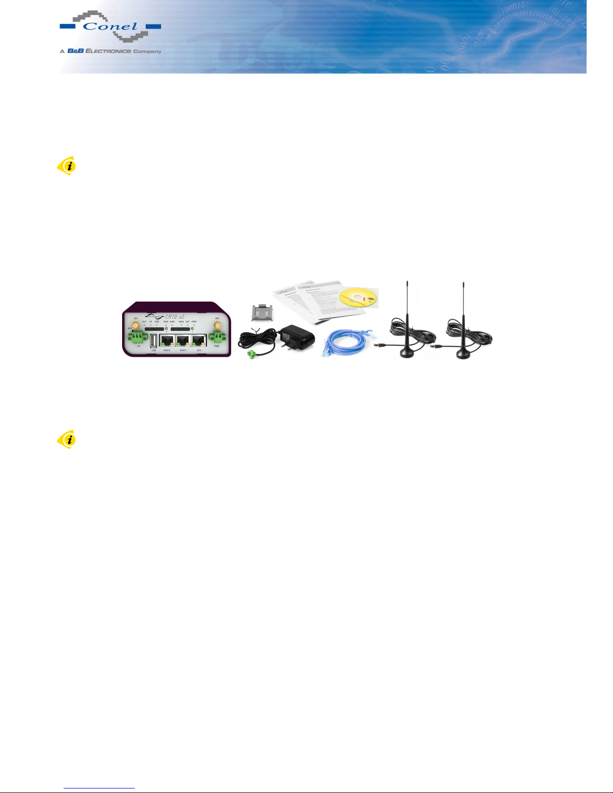
Basic delivered set of router includes:
• router,
• power supply,
• crossover UTP cable,
• two external antennas,
• clip for the DIN rail,
• installation CD containing instructions,
• paper start guide.
Figure 1: Contents of package
Note: The router box and DIN mount are supplied in a metal case in the SL version.
The router can also be supplied as expansion accessories:
• One (Basic version) or two (Full version) expansion ports: RS232, RS485/422, MBUS,
ETHERNET, CNT, SWITCH, WIFI, WMBUS or SDH. Separation columns for mounting
expansion boards are included.
4
Page 11
5. ROUTER DESIGN
5. Router design
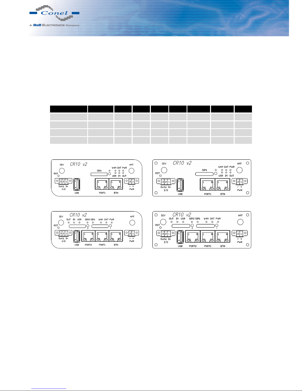
5.1 Router versions
CR10 v2 router is supplied in the following versions:
Box SIM1 SIM2 I/O USB PORT1 PORT2 ETH
CR10 v2B Plastic
CR10 v2B SL Metal
CR10 v2F Plastic
CR10 v2F SL Metal
Table 1: Router versions
Figure 2: Front panel CR10 v2B
Figure 3: Front panel CR10 v2F
Figure 4: Front panel CR10 v2B SL
Figure 5: Front panel CR10 v2F SL
5
Page 12
5. ROUTER DESIGN
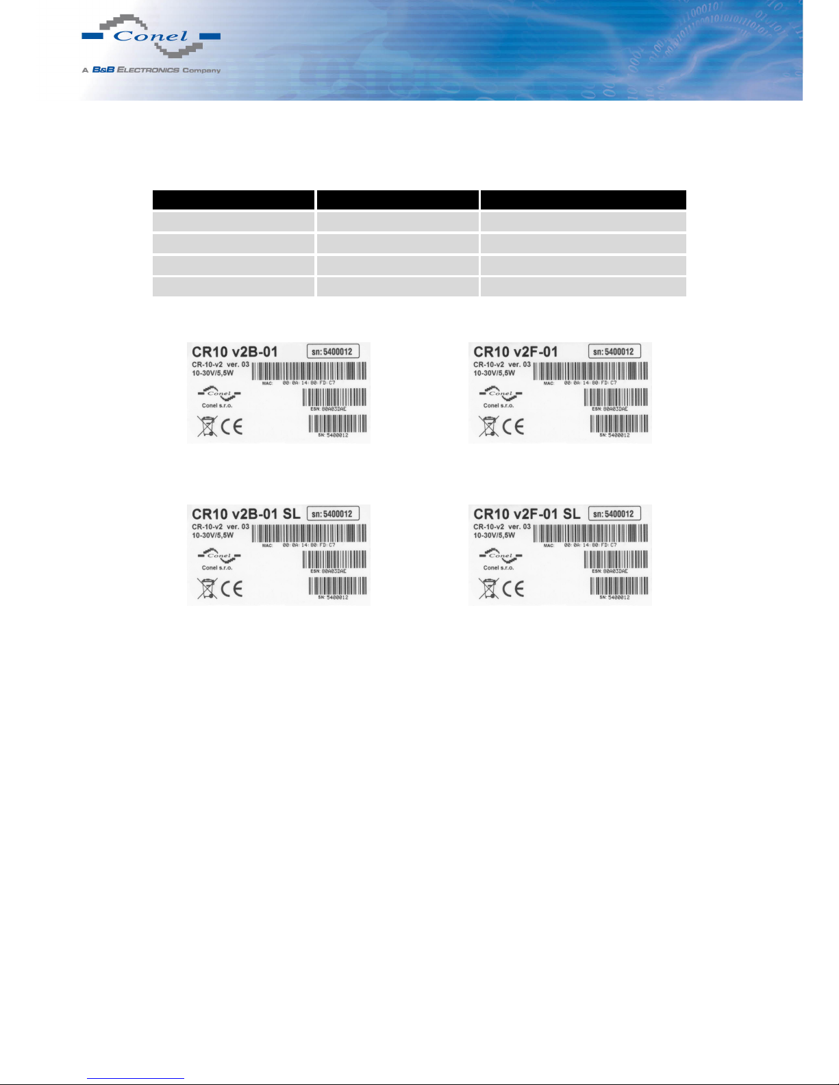
5.2 Delivery identification
Trade name Type name Other
CR10 v2B CR-10-v2 Basic version
CR10 v2B SL CR-10-v2 Basic version in the metal box
CR10 v2F CR-10-v2 Full version
CR10 v2F SL CR-10-v2 Full version in the metal box
Table 2: Delivery identification
Figure 6: Label CR10 v2B
Figure 7: Label CR10 v2B SL
Figure 8: Label CR10 v2F
Figure 9: Label CR10 v2F SL
6
Page 13
5. ROUTER DESIGN
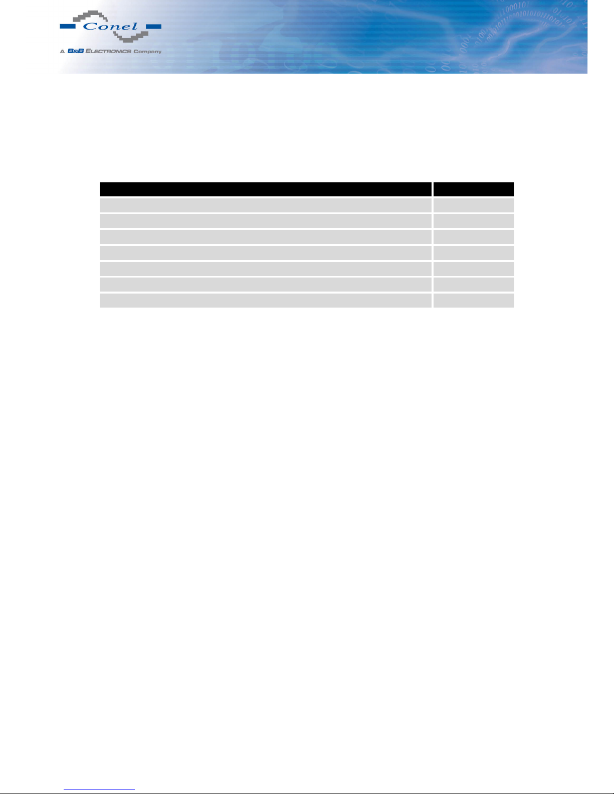
5.3 Version of firmware module
Each operator can have another CDMA network, so it is necessary to generate a special
firmware for each operator. Version of the firmware is indicated by two-digit code in the name
of the product.
Operator Code
Poland Orange 01
Poland Plus 02
Czech Republic O2 03
Germany Inet 04
Sweden Net.1 05
Norway Net.1 06
Russia Skylink 07
Table 3: Version of firmware module
Example of trade name: CR10 v2B-01
Example of type name: CR-10-v2B ver. 01
7
Page 14
5. ROUTER DESIGN
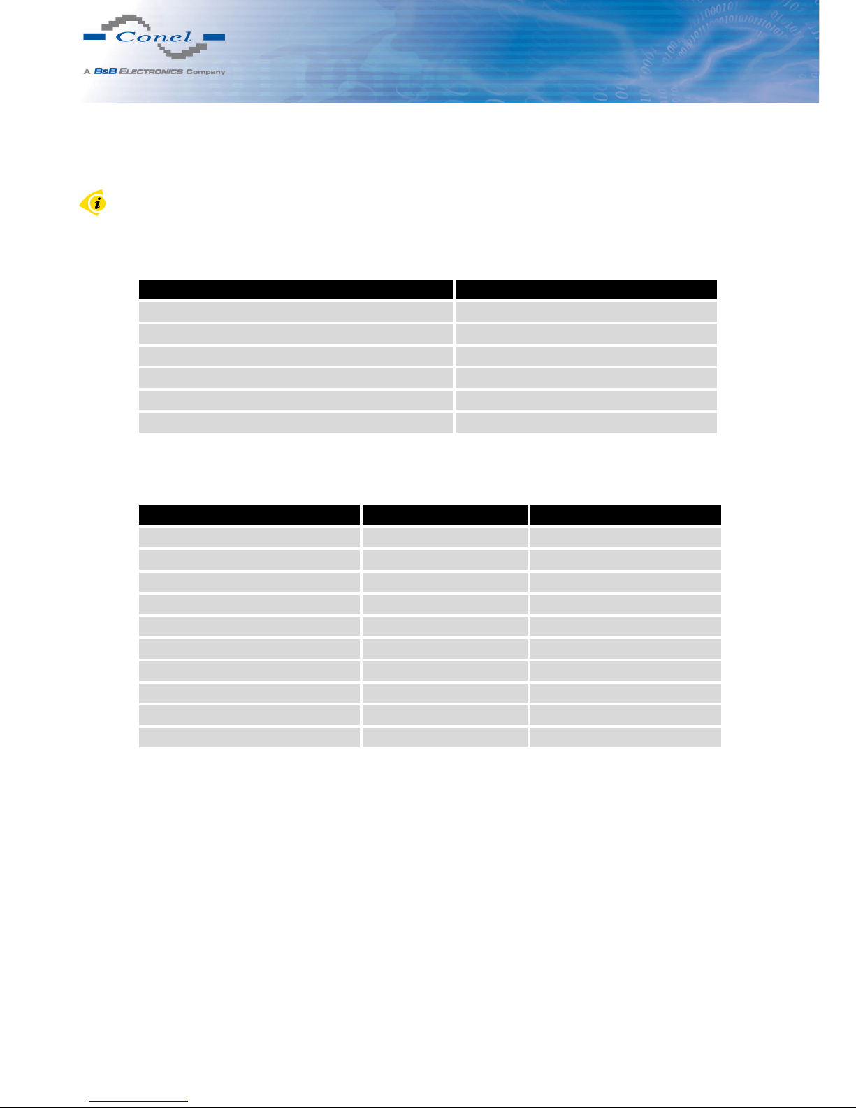
5.4 Ordering codes
Order codes are given for the Polish operator Orange. Another operator can be selected
by changing two digits according to Table 3 Version of firmware module on page 7.
5.4.1 Basic version
Expansion port Ordering code
Version without expansion por t CR10 v2B-01 set
Version with Ethernet expansion port CR10 v2B-01 ETH set
Version with RS232 expansion port CR10 v2B-01 RS232 set
Version with RS485 expansion port CR10 v2B-01 RS458 set
Version with MBUS expansion port CR10 v2B-01 MBUS set
Version with CNT expansion port CR10 v2B-01 CNT set
Table 4: Ordering codes of basic version
5.4.2 Full version
Expansion port Possible participation Ordering code
Version without expansion por t CR10 v2F-01 set
Version with Ethernet exp. port PORT1 CR10 v2F-01 ETH set
Version with RS232 exp. port PORT1 a PORT2 CR10 v2F-01 RS232 set
Version with RS485 exp.port PORT1 a PORT2 CR10 v2F-01 RS458 set
Version with MBUS exp. port PORT1 a PORT2 CR10 v2F-01 MBUS set
Version with CNT exp. port PORT1 CR10 v2F-01 CNT set
Version with SWITCH exp. port PORT1 + PORT2 CR10 v2F-01 SWITCH set
Version with WIFI exp. port PORT2 CR10 v2F-01 WIFI set
Version with WMBUS exp. port PORT2 CR10 v2F-01 WMBUS set
Version with SDH exp. port PORT2 CR10 v2F-01 SDH set
Table 5: Ordering codes of full version
Second expansion port is written after first expansion port in the ordering code.
Example:
• Full version with Ethernet and RS232 port: CR10 v2F-01 ETH RS232 set.
• Full version with Ethernet and RS232 port in metal cover:
CR10 v2F-01 ETH RS232 SL set.
8
Page 15
5. ROUTER DESIGN
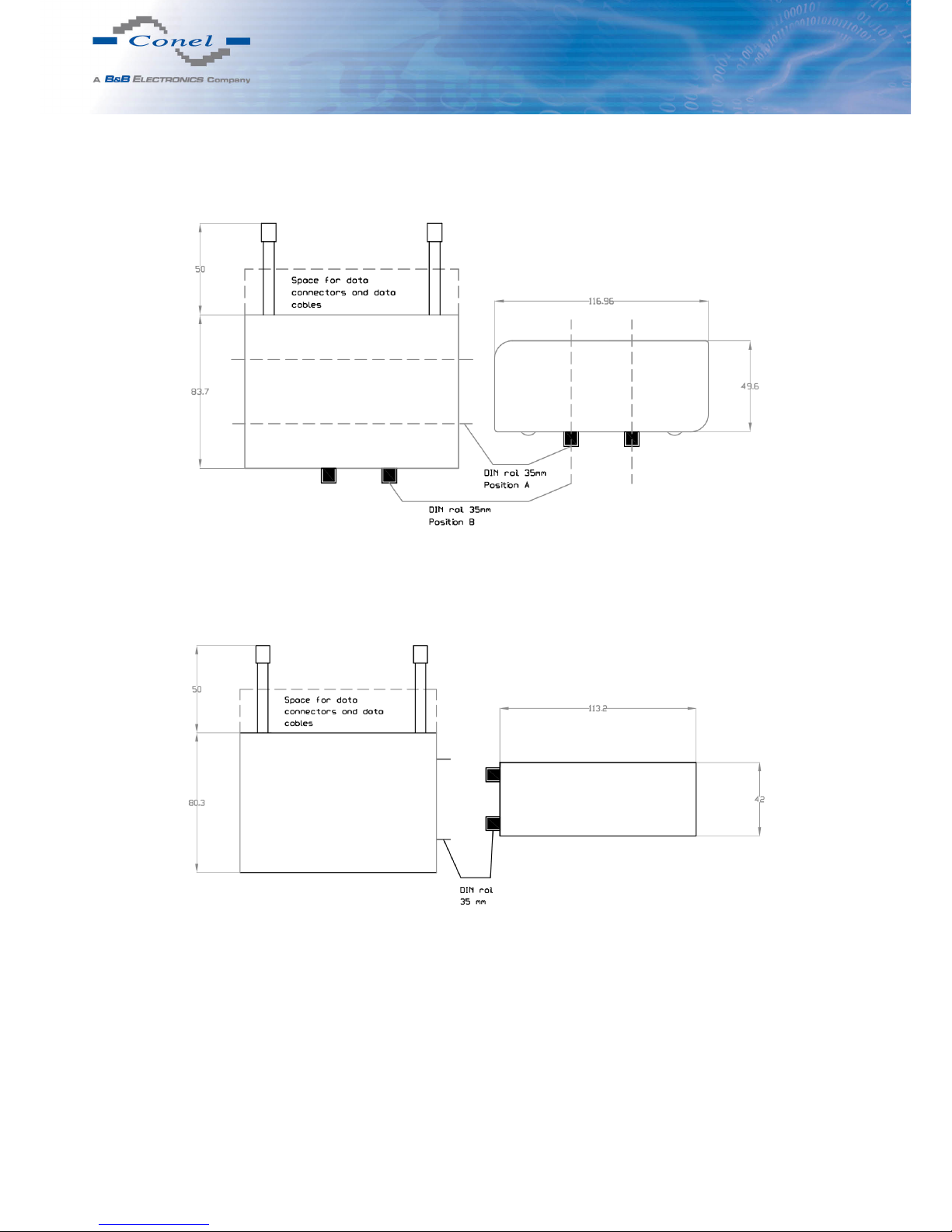
5.5 Basic dimensions of plastic box
Figure 10: Basic dimensions of plastic box
5.6 Basic dimensions of metal box
Figure 11: Basic dimensions of metal box
9
Page 16
5. ROUTER DESIGN
5.7 Mechanical dimensions and mounting recommendations
Mounting recommendations:
• possibility to be put on a work surface,
• DIN rail with clips CKD2 (ELPAC clip SL for metal version) are included.
For the most of applications with a built-in router in a switch board it is possible to recognize
two kinds of environments:
• no public and industry environment of low voltage with high interference,
• public environment of low voltage without high interference.
For both of these environments it is possible to mount router to a switch board, the following
there is no need to have examination immunity or issues in connection with EMC according to
EN 60439-1 ed.2:00 + A1:04.
For compliance of EN 60439-1 ed.2:00 + A1:04 specification it is necessary to observe next
assembly of the router to the switch – board:
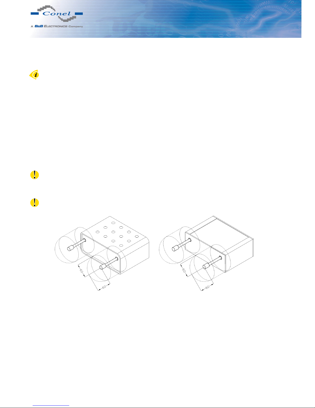
• for whip antennas we recommend to observe a distance of 6 cm from cables and metal
surfaces on every side according to the next picture due to the elimination of interference, while using an external antenna except for the switch-board it is necessary to fit a
lightening conductor,
• before mounting a router on sheet-steel we recommend using an external antenna,
Figure 12: Space around antennas Figure 13: Space around antennas for SL
10
Page 17
5. ROUTER DESIGN
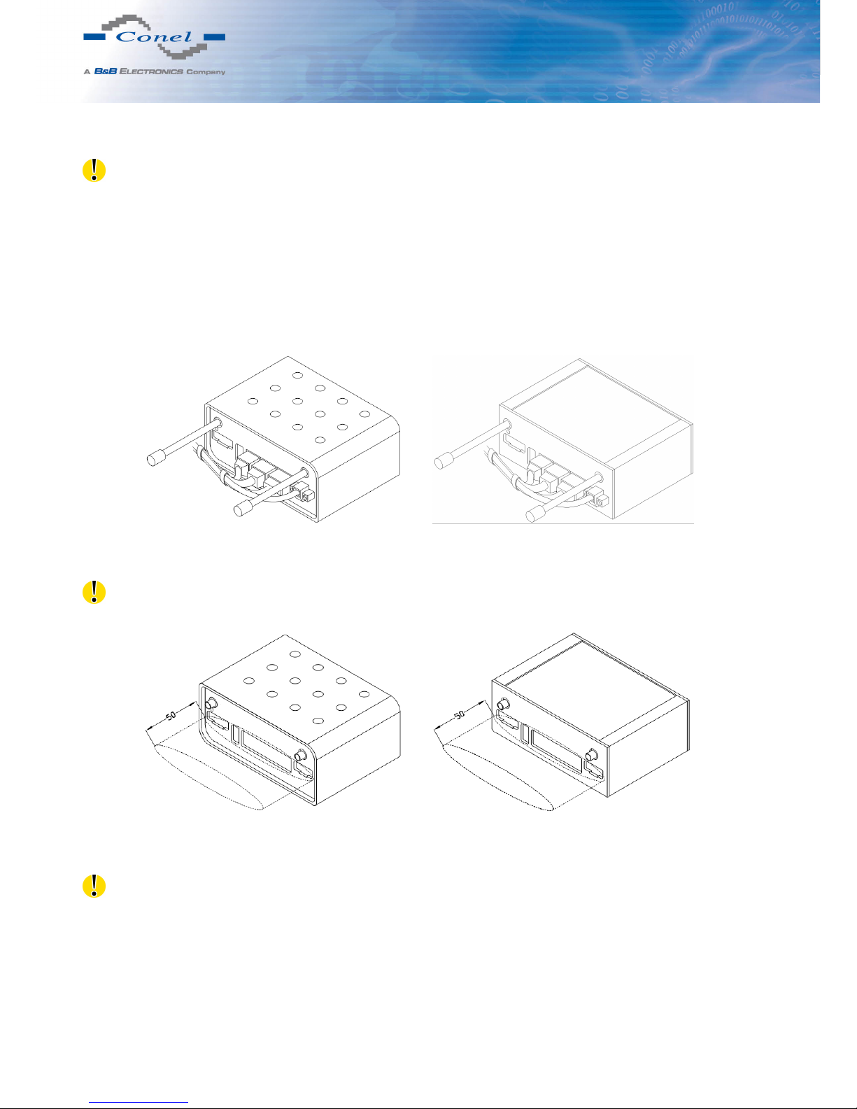
• For every cables we recommend to bind the bunch according to the following picture, we
recommend for this use:
– Length of the bunch (combination of power supply and data cables) can be max-
imum 1,5 m. If the length of data cables exceeds 1,5 m or in the event of, the
cable leads towards the switch – board. We recommend installing over – voltage
protectors (surge suppressors).
– With data cables they mustn’t carry cables with reticular tension ∼ 230 V/50 Hz.
– All signals to sensors must be twisted pairs.
Figure 14: Cable routing Figure 15: Cable routing for SL version
• Suf ficient space must be left before individual connectors for handling of cables,
Figure 16: Space in front of connectors Figure 17: Space in front of connectors – SL
• For correct function of the router we recommend to use in the switch-board earth-bonding
distribution frame for grounding of power supply of router, data cables and antenna.
11
Page 18
5. ROUTER DESIGN
5.8 Removing from the DIN rail
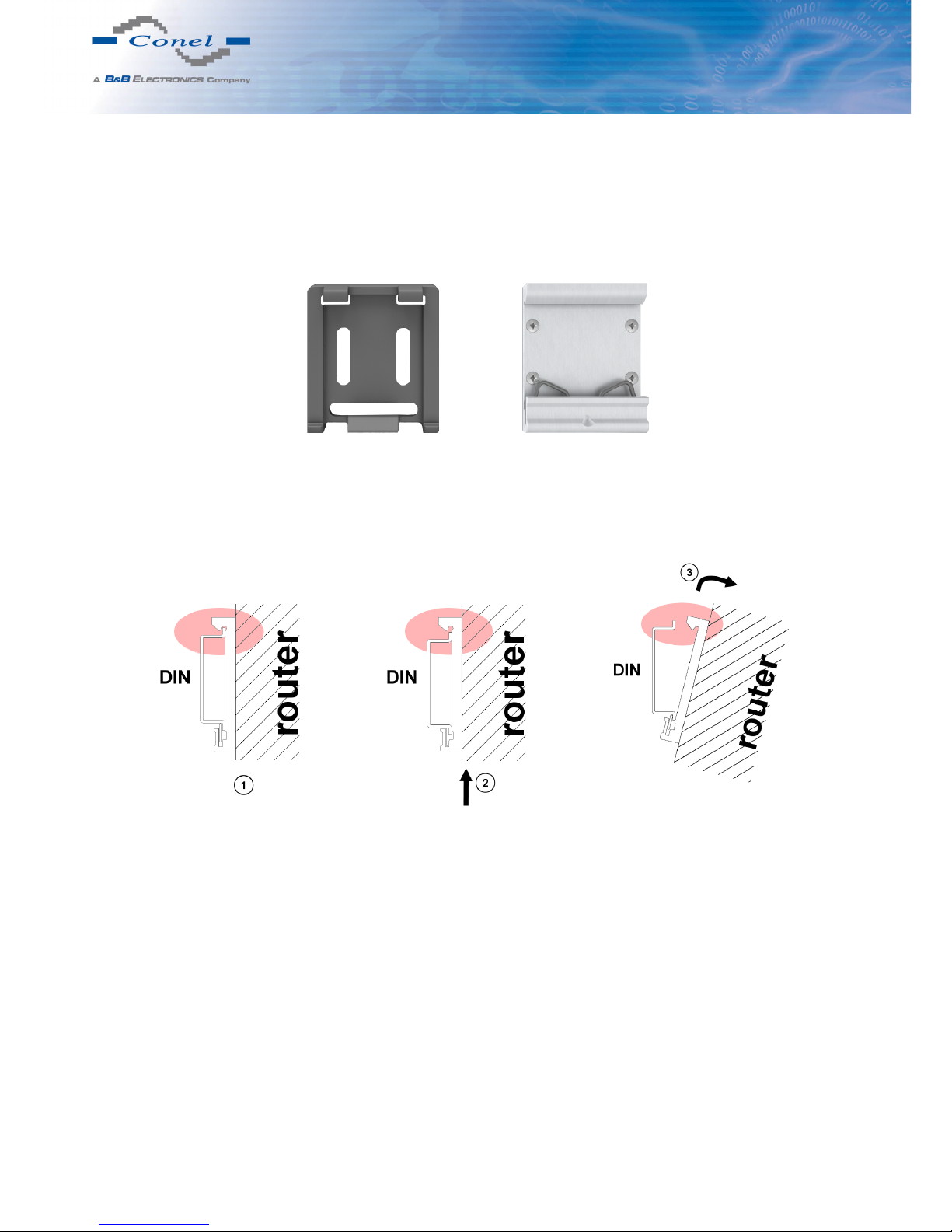
Default position of CPD2 holder (or CKD2 holder for SL version), which is used for
mounting the router on a DIN rail, is shown in the following figure:
Figure 18: Default position of DIN holder
For removing from the DIN rail it is necessary to lightly push upward the router so that
the top part of the CPD2 holder (or CKD2 for SL version) hitched to the DIN rail get out
of this rail and then fold out the top part of the router away from the DIN rail.
Figure 19: Removing from the DIN rail
12
Page 19
5. ROUTER DESIGN
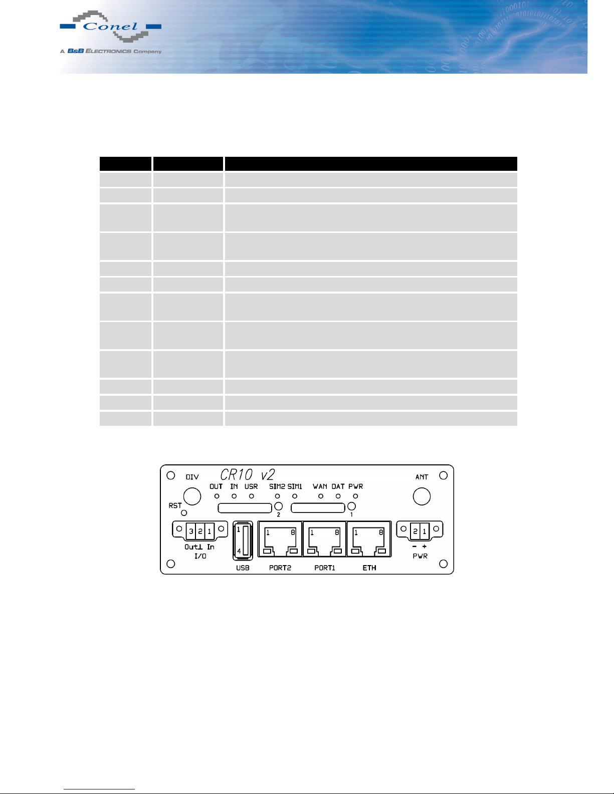
5.9 Description of the front panel
On the front panel is located:
Caption Connector Description
PWR 2-pin Connector for the power supply adapter.
ETH RJ45 Connector for connection into the local computer network.
PORT1 RJ45 Connector for expansion port RS232, RS458/422, MBUS,
ETHERNET, CNT or SWITCH.
PORT2 RJ45 Connector for expansion port RS232, RS485/422, MBUS,
SWITCH, WIFI, WMBUS or SDH (only FULL version).
ANT SMA Connector for main antenna.
DIV SMA Connector for diversity antenna.
WIFI R-SMA Connector for WIFI antenna. Only when router is equipped
with an expansion port WIFI.
WMBUS SMA Connector for WMBUS antenna. Only when it is equipped
with an expansion port WMBUS.
USB USB-A Host Connector for connection of USB devices to the router. Sup-
ports devices with PL-2303 and FTDI USB/RS232 converters.
I/O 3-pin Connector for connection of the binary input and output.
SIM1 — Holder for the first SIM card.
SIM2 — Holder for the second SIM card (only FULL version).
Table 6: Front panel description
Figure 20: Front panel CR10 v2F SL
13
Page 20
5. ROUTER DESIGN
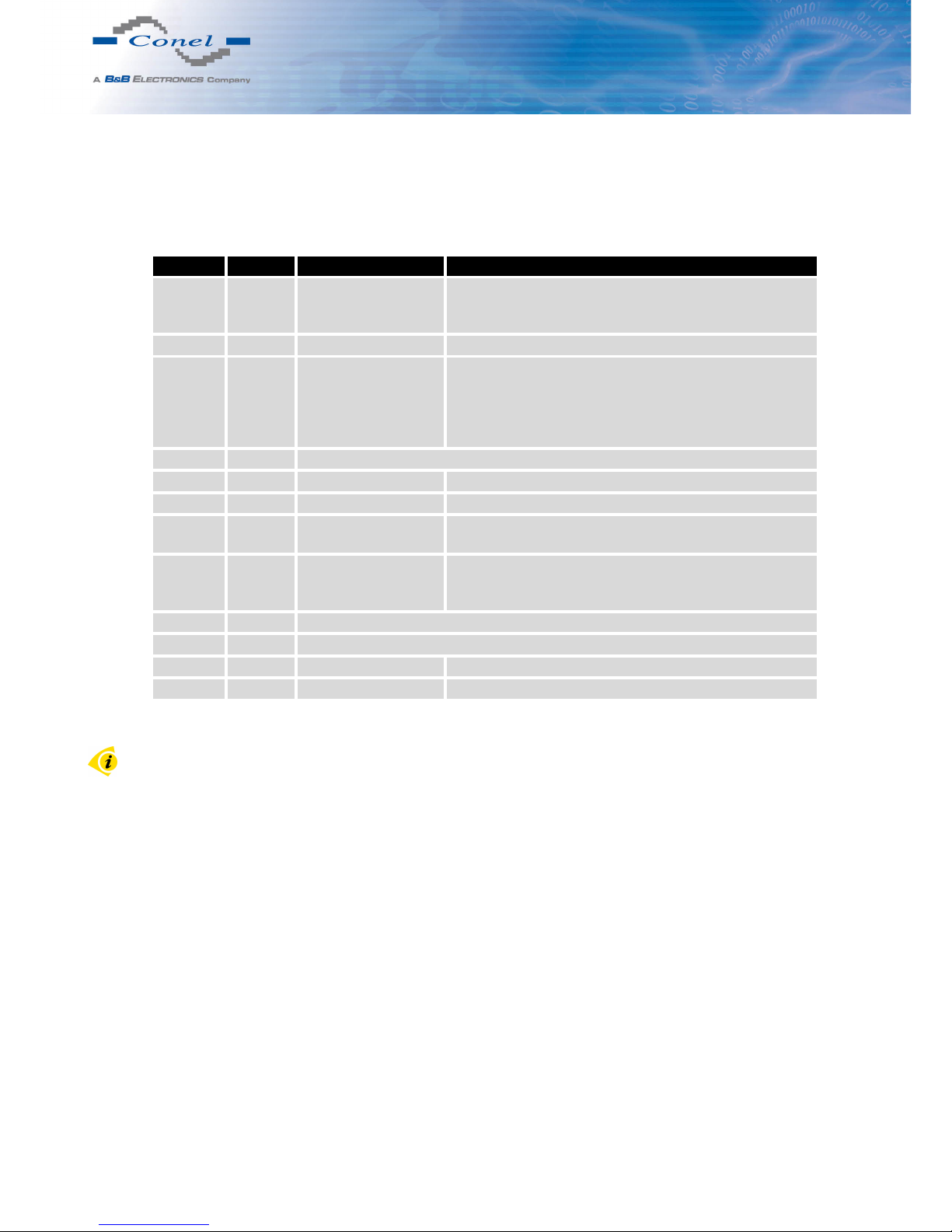
5.9.1 Status indication
About router status inform eight led indicators on the front panel and on every port are two
LED indicators, which inform about port status.
Caption Color State Description
PWR Green Blinking
On
Fast blinking
Router is ready
Starting of the router
Updating firmware
DAT Red Blinking Communication in progress on radio channel
WAN Yellow 1x flash per second
2x flash per second
3x flash per second
Signal strength is from –50 dBm to –69 dBm
Signal strength is from –70 dBm to –89 dBm or difference between neighbours cells is exactly 3 dBm
Signal strength is from –90 dBm to –113 dBm or difference between neighbours cells is smaller than 3 dBm
USR Yellow Function selected by user
OUT Green On Binary output active
IN Green On Binary input active
ETH Green On
Off
Selected 100 Mbit/s
Selected 10 Mbit/s
ETH Yellow On
Blinking
Off
The network cable is connected
Data transmission
The network cable is not connected
PORT Green Depends on the expansion port (see user’s guide of used port)
PORT Yellow Depends on the expansion port (see user’s guide of used port)
SIM1 Yellow On SIM card 1 is active
SIM2 Yellow On SIM card 2 is active
Table 7: Router status indication
State indication of WAN LED is updated every 10 seconds.
14
Page 21
5. ROUTER DESIGN
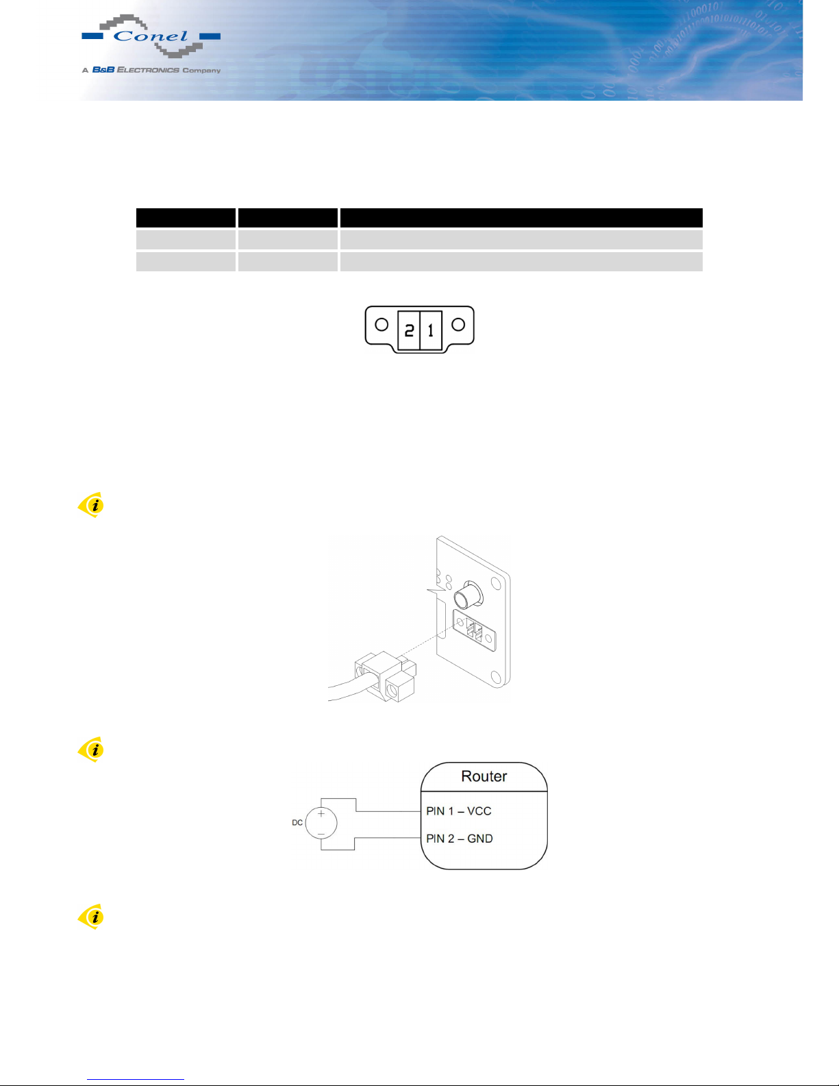
5.9.2 Power connector PWR
Panel socket 2-pin.
Pin number Signal mark Description
1 VCC(+) Positive pole of DC supply voltage (+10 to +30 V DC)
2 GND(-) Negative pole of DC supply voltage
Table 8: Connection of power connector
Figure 21: Power connector
Power supply for router is required between +10 V to +30 V DC supply. Protection against
reversed polarity without signaling is built into the router.
The power consumption during receiving is 2,3 W. The peak power consumption during
data sending is 5,5 W. However, values of consumption can be increased, if some expansion
port is eqquipped. For correct operation it is necessary that the power source is able to supply
a peak current of 1 A.
Connector on the power cable connects into the power connector on the router head and
tightens locking screws (see figure below).
Figure 22: Connection of power supply connector
Circuit example:
Figure 23: Connection of power supply
The positive pole VCC is marked by a red socket on the power.
15
Page 22
5. ROUTER DESIGN
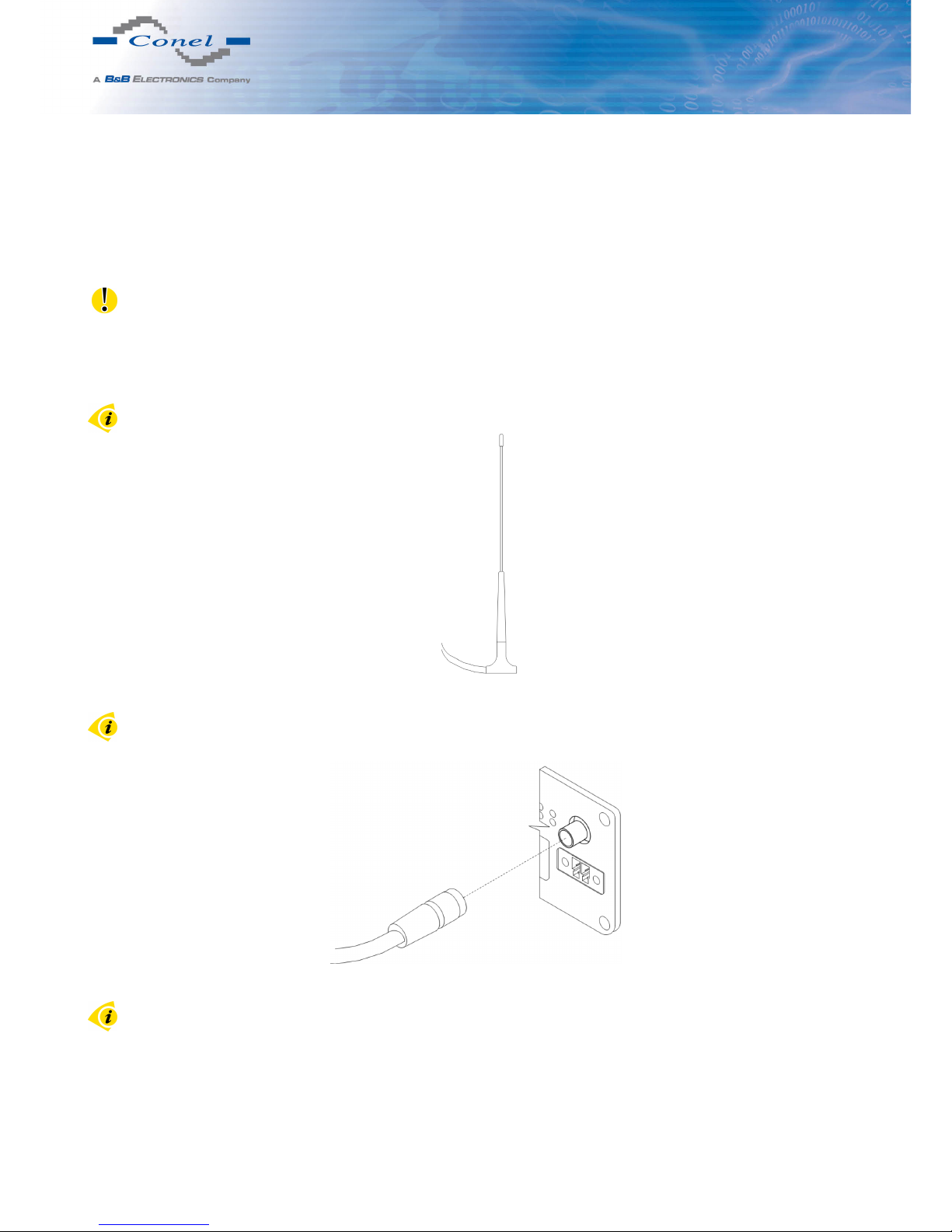
5.9.3 Antenna connector ANT, DIV (alternatively WIFI or WMBUS)
Main and diversity antennas are connected to the router using the SMA connector on the
front panel. If WIFI or WMBUS expansion port is eqquiped on customer’s request, on the front
panel is also available the third SMA antenna connector, through which the additional antenna
can be connected (it is reverse connector R-SMA in case of the WIFI expansion port).
The router can not operate without the main antenna connected labeled as ANT.
ANT connector is used to connect the main antenna router. To connect the diversity antenna is used the second antenna connector marked as DIV. If WIFI or WMBUS expansion
port is eqquiped on customer’s request, there is also available WIFI or WMBUS antenna connector for connecting corresponding antenna.
Example of antenna:
Figure 24: External antenna
For connection the antenna is used SMA connector. The antenna is connected by screwing
this antenna to the SMA connector on the front panel of the router (see figure below).
Figure 25: Connecting of the antenna
Diversity antenna improves radio features of the router at low signal strength.
16
Page 23
5. ROUTER DESIGN
5.9.4 SIM card reader
The SIM card reader for 3 V and 1,8 V SIM cards is located on the front panel of the router.
To initiate the router into operation it is necessary to insert an activated SIM card with unblocked PIN in the reader. The SIM cards might be of different adjusted APN (Access Point
Name).
Changing the SIM card:
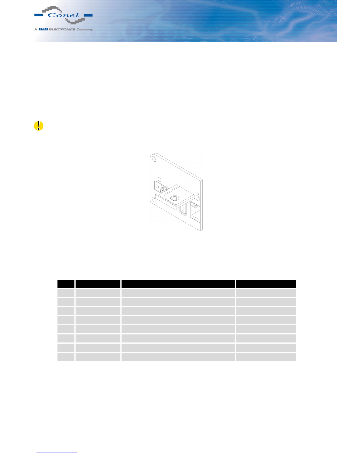
Before handling of the SIM card turn off the router and disconnect it from power supply.
Press the small yellow button to eject the reader holder. Insert the SIM card into the reader
holder and slide it in the reader (see figure below).
Figure 26: Ejected SIM holder
5.9.5 Ethernet port
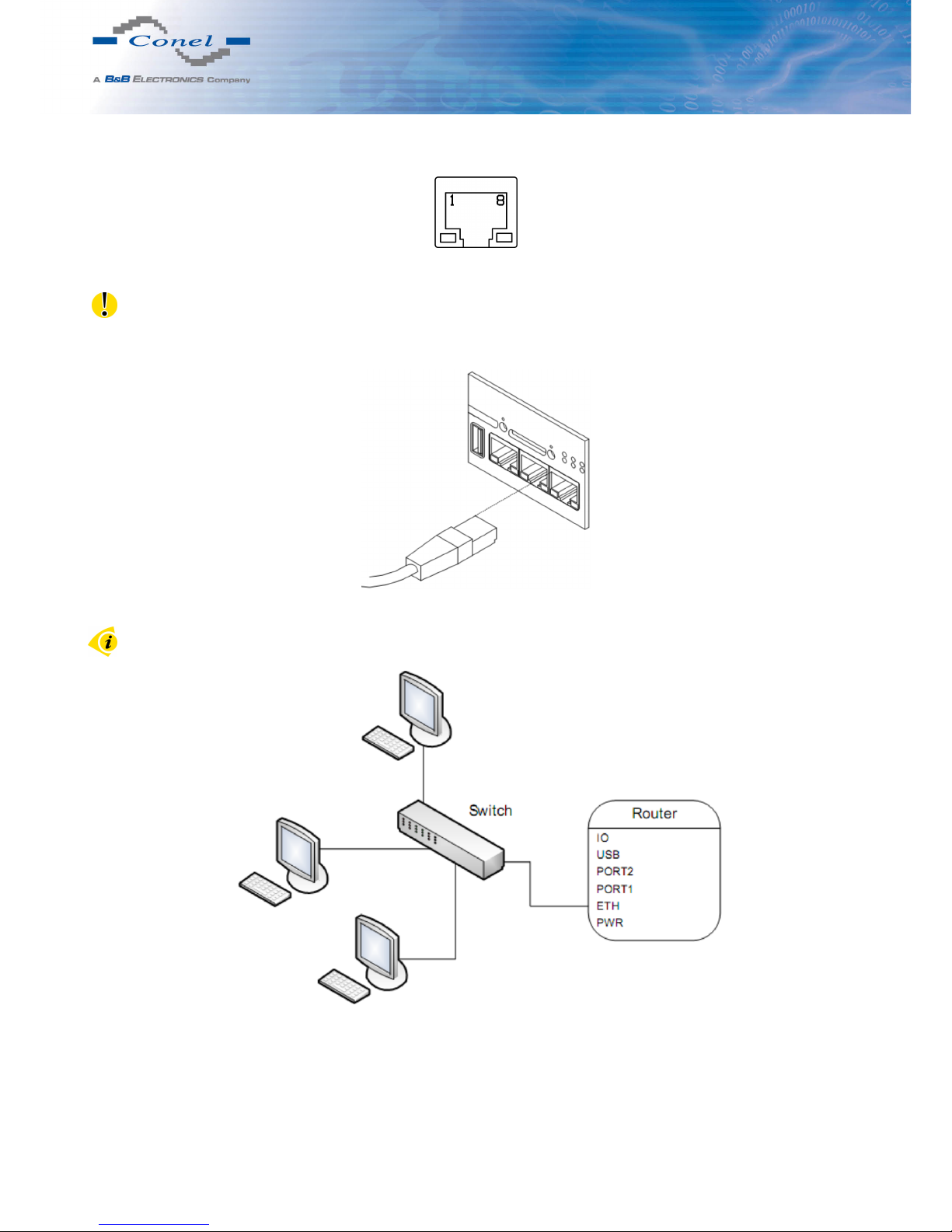
Panel socket RJ45.
Pin Signal mark Description Data flow direction
1 TXD+ Transmit Data – positive pole Input/Output
2 TXD- Transmit Data – negative pole Input/Output
3 RXD+ Receive Data – positive pole Input/Output
4 — —
5 — —
6 RXD- Receive Data – negative pole Input/Output
7 — —
8 — —
Table 9: Connection of Ethernet connector
17
Page 24
5. ROUTER DESIGN
Figure 27: Ethernet connector
ATTENTION! Port ETH is not POE (Power Over Ethernet) compatible!
Ethernet cable plug into the RJ45 connector labeled as ETH (see figure below).
Figure 28: Connection of ethernet cable
Example of the ETH router connection:
Figure 29: Example of router connection
18
Page 25
5. ROUTER DESIGN
5.9.6 PORT1
The PORT1 is equipped on customer’s request with one of the offered expansion ports:
• RS232
• RS485/422
• ETHERNET
• MBUS
• CNT
• SWITCH (together with PORT2)
Description and examples of expansion ports connection can be found in user’s guide for
corresponding expansion port.
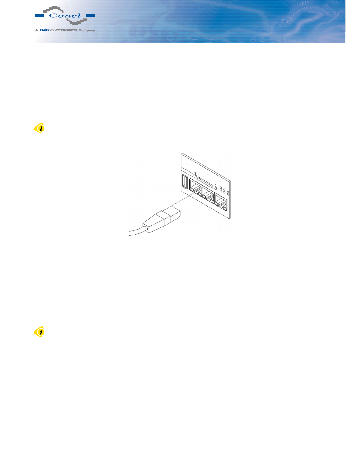
PORT1 cable plug into the RJ45 connector labeled as PORT1 (see figure below).
Figure 30: PORT1 cable connection
5.9.7 PORT2
The PORT2 is equipped on customer’s request with one of the offered expansion ports:
• RS232
• RS485/422
• MBUS
• SDH
• SWITCH (together with PORT1)
• WIFI
• WMBUS
PORT2 is available only in the Full version of the router! Description and examples of
expansion ports connection can be found in user’s guide for corresponding expansion port.
19
Page 26
5. ROUTER DESIGN
PORT2 cable plug into the RJ45 connector labeled as PORT1 (see figure below).
Figure 31: PORT2 cable connection
5.9.8 USB Port
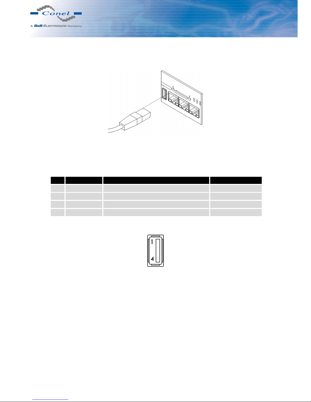
Panel socket USB-A.
Pin Signal mark Description Data flow direction
1 +5 V Positive pole of 5 V DC supply voltage
2 USB data - USB data signal – negative pole Input/Output
3 USB data + USB data signal – positive pole Input/Output
4 GND Negative pole of DC supply voltage
Table 10: Connection of USB connector
Figure 32: USB connector
20
Page 27
5. ROUTER DESIGN
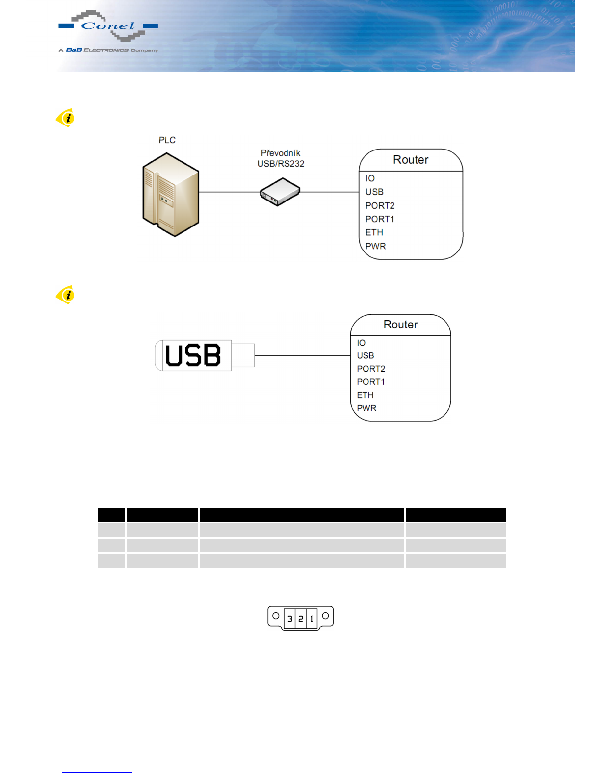
Example of connecting devices with serial interface to the USB:
Figure 33: Connection PLC to the router
Example of connecting of USB flash disk to the USB:
Figure 34: Connection flash memory to the router
5.9.9 I/O Port
Panel socket 3pin.
Pin Signal mark Description Data flow direction
1 BIN0 Binary input Input
2 GND Signálová zem
3 OUT0 Binary output Output
Table 11: Connection of I/O port
Figure 35: I/O connector
21
Page 28
5. ROUTER DESIGN
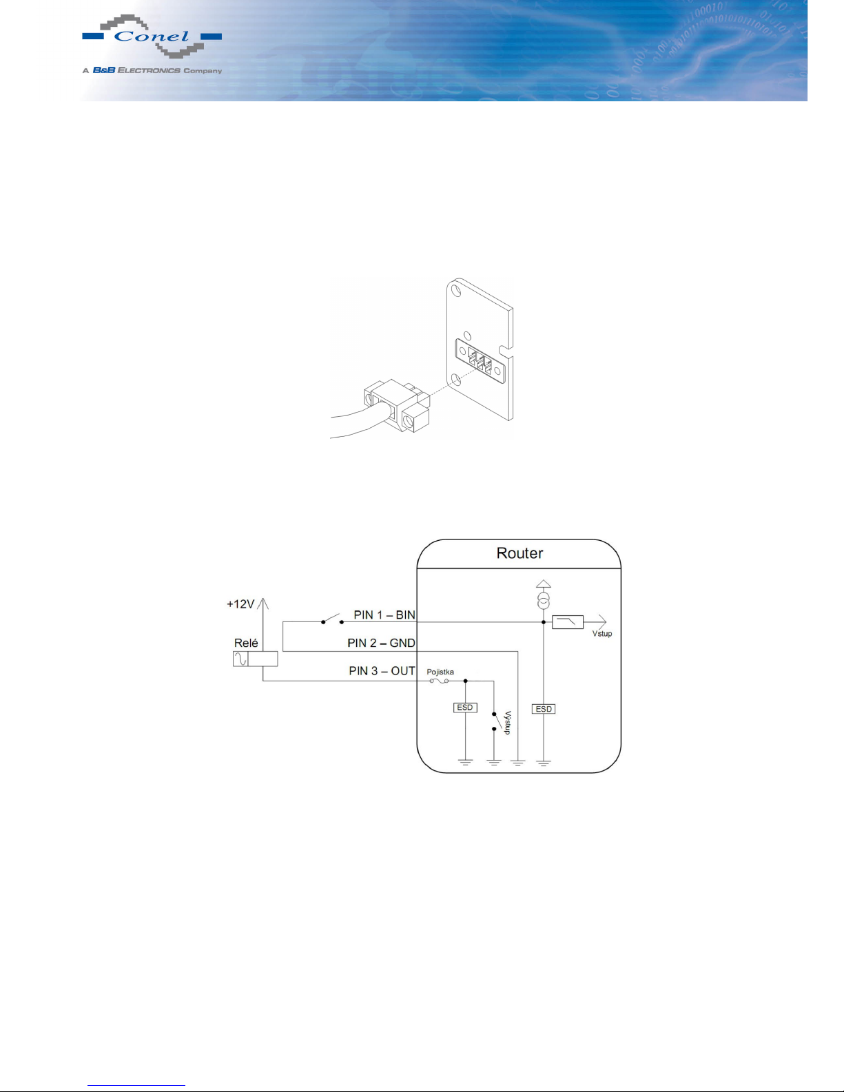
The user interface I/O is for processing of binary input signal and to control (settings) of
binary output signal. Binary output is not switched to ground in the default configuration.
Maximum load binary output is 30 V / 100 mA. The constant current supplied by the binary
input is 3 mA.
Connector I/O cable connect into the I/O connector on the router head and tighten locking
screws (see figure below).
Figure 36: Connection of I/O cable
Circuit example of a binary input or output equipment with router:
Figure 37: Connection of input and output to the router
22
Page 29
5. ROUTER DESIGN
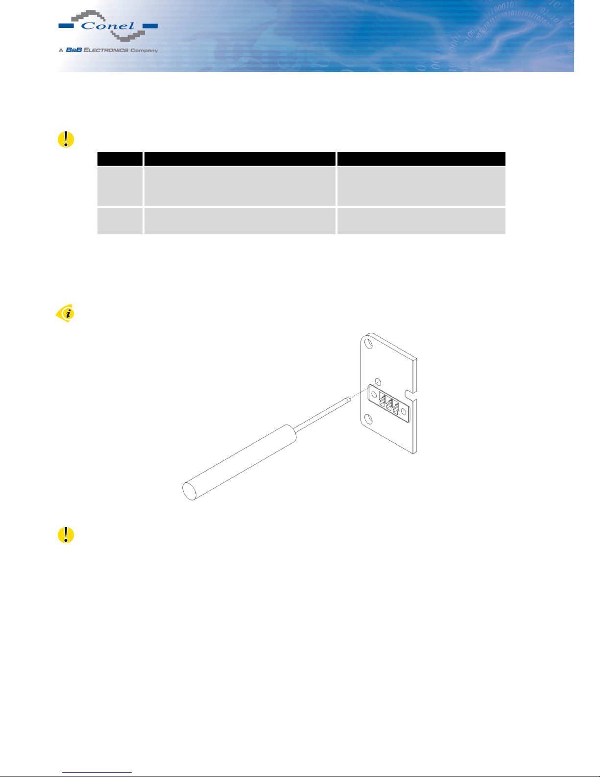
5.9.10 Reset
It is important to distinguish between reset and reboot the router.
Action Router behavior Invoking events
Reboot Turn off and then turn on router Disconnect and connect the power,
Press the Reboot button in the web
configuration
Reset Restore default configuration and reboot
the router
Press RST button
Table 12: Description of reset and restart router
After green LED starts to blink it is possible to restore initial settings of the router by pressing button RST on front panel. After press button RST it is restoration of default configuration
and reboot (green LED will be on).
For pressing the RST button could be used a narrow screwdriver.
Figure 38: Router reset
We recommend to backup your router configuration (see Configuration manual), because
after reset router set configuration to the initial state.
23
Page 30
6. FIRST USE
6. First use
6.1 Connecting the router before first use
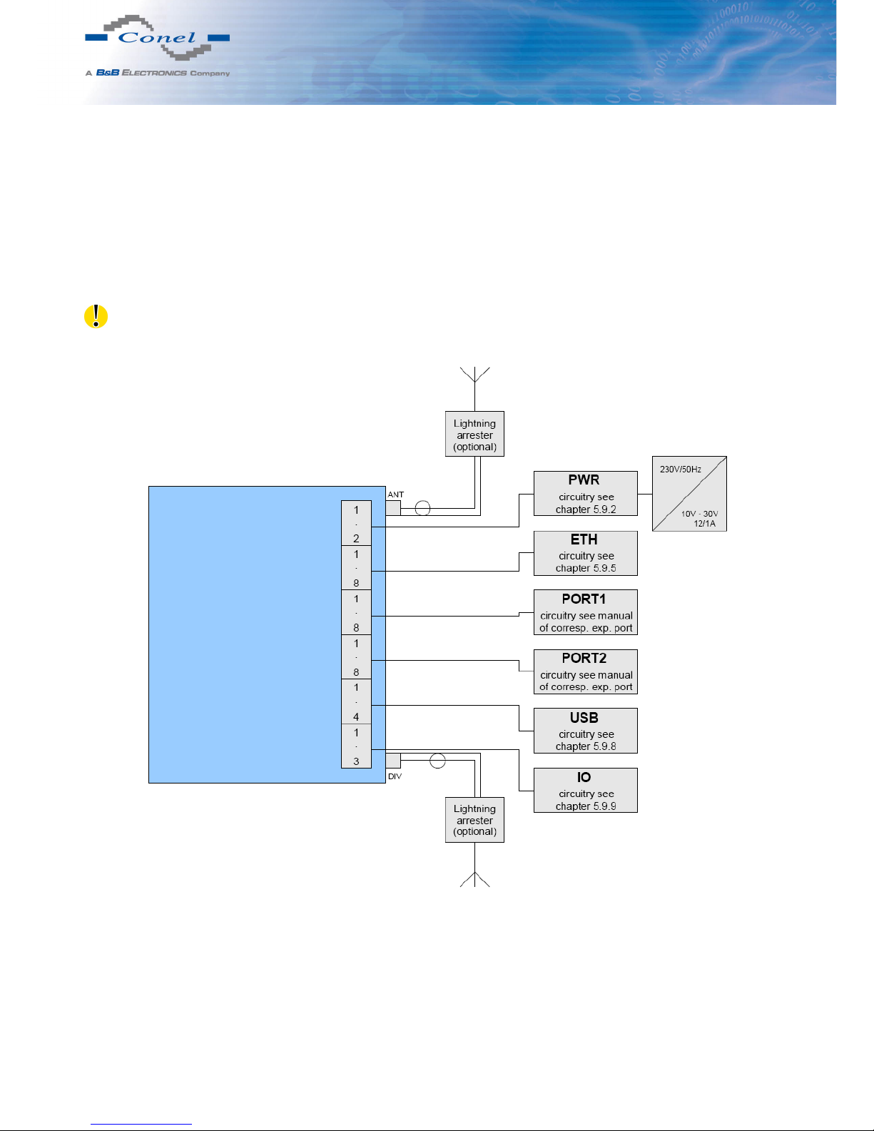
Before you give up the router, it is necessary to connect all components needed for the
operation of your applications and the SIM card must be inserted (see figure below).
The router can not operate w ithout connected antenna, SIM card and power supply. If the
antenna is not connected, router can be demaged.
Figure 40: Router connection
24
Page 31
6. FIRST USE
6.2 Start
The router is set up connecting the power supply to the router. In the default setting
the router starts to login automatically to the preset APN. Device on the Ethernet port DHCP
server will assign addresses. The behavior of the router can be modified by means of the web
or Telnet interface, which is described in the configuration manual.
The power consumption during receiving is 2,3 W. The peak power consumption during
data sending is 5,5 W. However, values of consumption can be increased, if some expansion
port is eqquipped. For correct operation it is necessary that the power source is able to supply
a peak current of 1 A.
6.3 Configuration
Attention! If the SIM card is not inserted in the router, then it is impossible to operate. The
inserted SIM card must have activated CDMA.
6.3.1 Configuration over web browser
Monitoring of the status, configuration and administration of the router can be performed
by means of the web interface, which is available after insertion of IP address of the router
into the web browser. The default IP address of the router is 192.168.1.1. Configuration may
be performed only by the user "root" with initial password "root".
A detailed description of the router settings via the Web interface can be found in the configuration manual.
6.3.2 Configuration over Telnet
Monitoring of status, configuration and administration of the router can be performed
by means of the Telnet interface. After IP address entry to the Telnet interface it is possible to configure the router by the help of commands. The default IP address of the router
is 192.168.1.1. Configuration may be performed only by the user "root" with initial password
"root".
A detailed description of the router settings via the Telnet interface can be found in the configuration manual.
25
Page 32
7. TECHNICAL PARAMETERS
7. Technical parameters
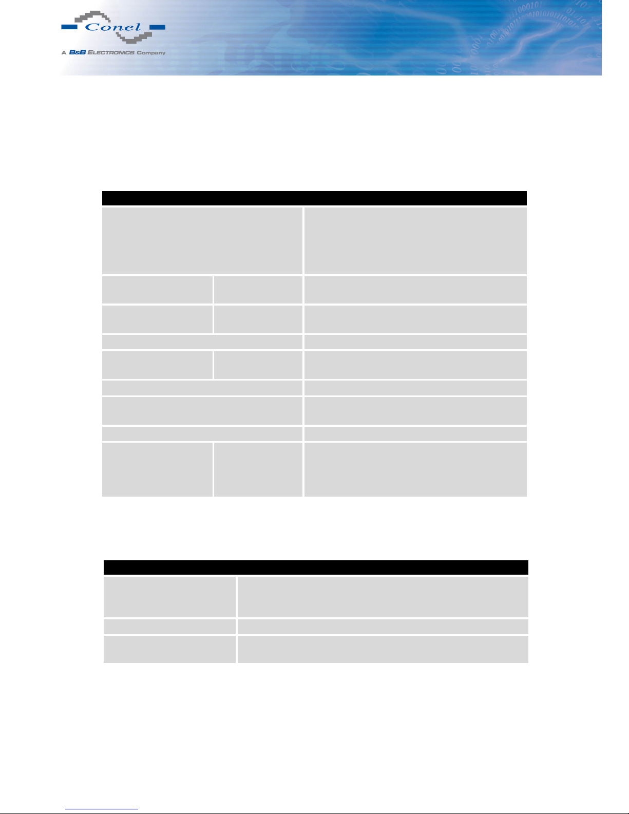
7.1 Technical parameters of router
CR10 v2
Complies with standards EN 301 526, v1.1.1,
EN 62311:2008
ETSI EN 301 489-25 v2.3.2,
EN 60950-1:06 ed.2 + A11:09 + A1:10 +
A12:11 + Opr. 1:12
Temperature range Function
Storage
-30◦C to +60◦C
-40◦C to +85◦C
Protection Freely
In switch board
IP20
IP56
Supply voltage 10 to 30 V DC
Consumption Reception
CDMA
2,3 W
to 4 W
Dimensions 42 x 76 x 113 mm (DIN lišta 35 mm)
Weight CR10 v2 – 150 g
CR10 v2 SL – 280 g
Antenna connector SMA – 50 Ohm
User interface ETH
USB
PORT1
PORT2
Ethernet (10/100 Mbit/s)
USB 2.0
On customer’s request
On customer’s request
Table 12: Technical parameters of router
7.2 Technical parameters of module
CDMA modul
CDMA parameters Rev. A: Bit rate 3,1 Mbps (DL) / 1,8 Mbps (UL)
Rev. B: Bit rate 14,7 Mbps (DL) / 5,4 Mbps (UL)
Backward compatible with Rev.0
Transmit power +23,0 dBm ∼ +30,0 dBm
Supported bands 450MHz (Sub band A,B,L)
800MHz & 1900MHz dual or single
Table 13: Technical parameters of module
26
Page 33
7. TECHNICAL PARAMETERS
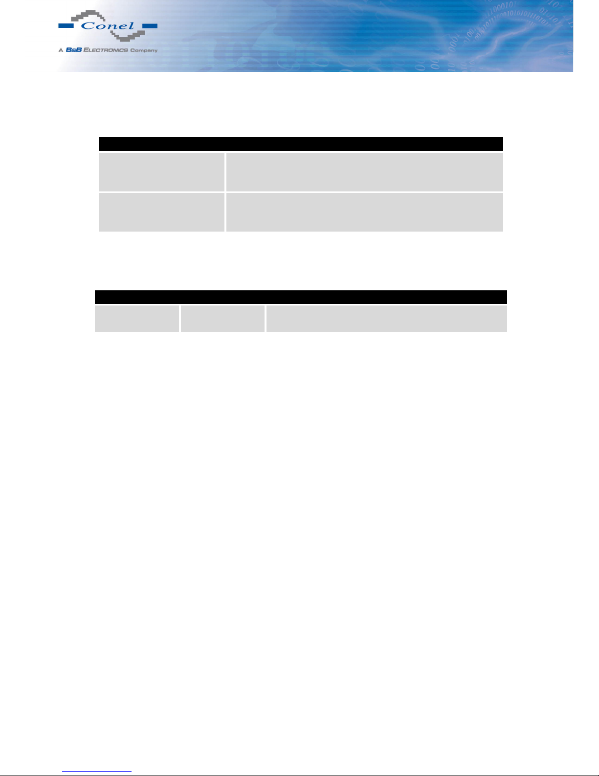
7.3 Technical parameters of processor
32b ARM mikroprocesor
Memory 512 Mb DDR SDRAM
128 Mb FLASH
1 Mb MRAM
Interface Serial interface RS232
Ethernet interface 10/100 Mbit/s
USB 2.0 interface
Table 14: Technical parameters of processor
7.4 Technical parameters I/O port
32b ARM mikroprocesor
Input/Output Binary input
Binary output
Reed contact with trigger level 1,3 up to 1,4 V
100 mA / max. 30 V
Table 15: Technical parameters I/O port
7.5 Technical parameters of expansion port
Technical parameters of the expansion ports are specified in separate manuals for expansion ports.
27
Page 34

8. RECOMMENDED LITERATURE
8. Recommended literature
[1] Conel: Start guide,
[2] Conel: Configuration manual,
[3] Conel: User’s manual – Expansion port RS232,
[4] Conel: User’s manual – Expansion port RS485/RS422,
[5] Conel: User’s manual – Expansion port MBUS,
[6] Conel: User’s manual – Expansion port CNT,
[7] Conel: User’s manual – Expansion port ETH,
[8] Conel: User’s manual – Expansion port SWITCH,
[9] Conel: User’s manual – Expansion port WIFI,
[10] Conel: User’s manual – Expansion port WMBUS,
[11] Conel: User’s manual – Expansion port SD,
[12] Conel: Application guide – Expansion port mounting,
[13] Conel: Application guide – Programmer guide.
28
Page 35

9. POSSIBLE PROBLEMS
9. Possible problems
Some network cards are able to be set in situation, when it is not possible to connect the
router. It is possible to solve this problem in the following steps:
• hand by selection communication rates 10 MB/s in property network cards,
• connect router over switch,
• start computer only after finalizing the start of the router.
29
Page 36

10. FAQ
10. FAQ
- I can’t get from internet on equipment, which is connected to router and I have NAT en-
abled.
• The device’s gateway has to be configured as the router.
- Router resets itself, connection on Ethernet fails.
• It is necessary to use an antenna, which will be situated far from power supply.
- I don’t get on web server at NAT.
• The remote http access of the router has to be disabled, default server address has
to be your web server and the gateway of the web server has to be the IP of router.
- PPP connection fails.
• Check signal power. If signal power is weak, you will have to use a better antenna.
If the environmental cells have a similar signal it will be necessary to use a directive
antenna. Signal levels have to be in the range -50 dBm and -90 dBm.
• It is necessary to set ping, which will check the connection and, in the case of fail
ping, restart connection.
- PPP connection won’t be established.
• Recheck GPRS settings - APN, name, password and IP address.
• Try to enter PIN – verification if the SIM card hasn’t set PIN code.
• In private APN it is appropriate to switch the DNS server send off.
• Switch log system on and observe where the error turns up.
- Connection fails on Ethernet or connection isn’t establishing.
• On ethernet interface of the router it is possible to switch auto negotiation off and
set a rate and duplex by hand.
- DynDNS not function.
• In private APN not functional.
• If the same IP address is recorded in your canonic name as dynamically assign
address, it means that the operator is using NAT or firewall.
• NAT is possible to verify by the help of the ping on address of your server with static
IP address and by the help of the router address verify and address in ping.
• Firewall is possible to verify, for example by remote access on web inter face.
30
Page 37

10. FAQ
• The operator doesn’t give out address DNS servers and without DNS server’s it
is impossible to connect to server dyndns.org. In log system will be this message:
– DynDNS daemon started
– Error resolving hostname: no such file or directory
– Connect to DynDNS server failed
- IPSec tunnel is establishing but communication doesn’t function.
• Probably it is badly set up route conditionals of connected equipment or it is bad set
up GW.
- FTP doesn’t function.
• Router doesn’t support the active FTP mode, supports the passive mode only.
- RS232 doesn’t function.
• It is necessary to verify present the expansion port RS232.
• Verify present the expansion port RS232 in router configuration in menu „external
port“, or verify connection locally by the help Telnet-Hyper terminal.
- L2TP or IPSec isn’t establishing.
• Verify the reason in the log system.
- I switched the router to offline mode by the SMS message, but the router is in online mode
after restart.
• Control SMS messages don’t change the router configuration. For example, if the
router is switched to offline mode by SMS message the router will be in this mode
up to next restart. This behaviour is the same for next all control SMS messages.
31
Page 38
11. CUSTOMERS SUPPORT
11. Customers support
You can find current information about this product on our website:
www.conel.cz
Upkeep-advices:
• The SIM-card must be handled carefully as with a credit card. Don’t bend, don’t scratch
on this and do not expose to static electricity.
• During cleaning of the router do not use aggressive chemicals, solvents and abrasive
cleaners!
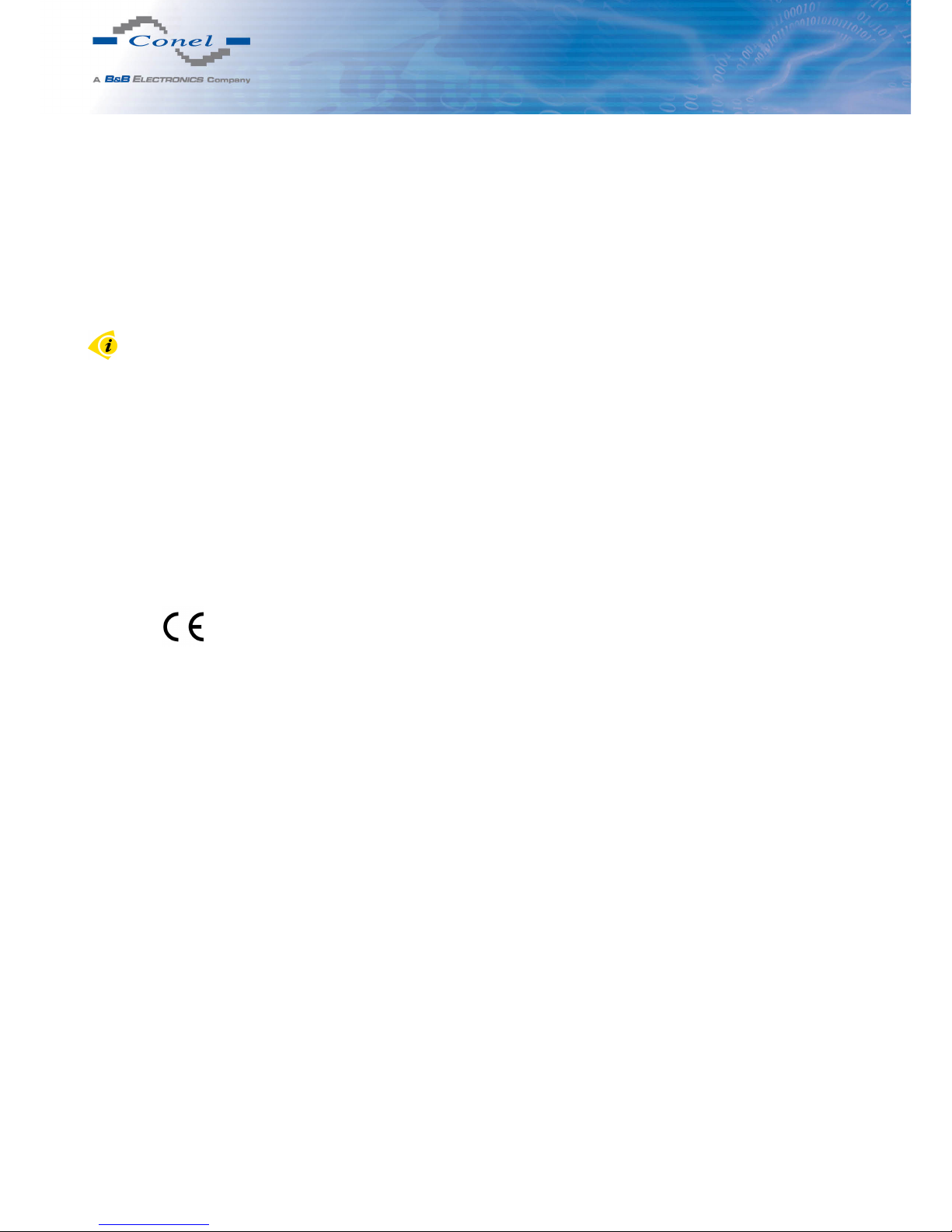
Conel Company hereby declares that the router narrated in this user’s guide fits all basic demands of directive 1999/5/EC (R&TTE).
Router fits values of coefficient SAR defined by association ICNIRP and values of "About protection of health before non-ionized radiation".
Declaration of conformity was issued and it is possible to find it on the enclosed
CD or at producer.
32
 Loading...