

Page 1
Page 2

CONTENTS
2
Contents
1. Safety instructions 4
2. Description of the CDA70 radio modem 5
2.1. General 5
2.2. Examples of possible applications 5
2.3. Description of individual components 5
2.3.1. Radio component 5
2.3.2. Modem component 6
2.3.3. Microcomputer 6
2.3.4. Inputs and outputs for telemetry 6
2.3.5. User interface protocols 7
2.3.6. Technical parameters 8
2.4. Radio modem status indication 9
2.5. User interfaces (connectors) 9
2.5.1. Connection of PORT1, PORT2 and PORT3 connectors (RS232) 10
2.5.2. Connection of PORT1 connectors (M-BUS) 11
2.5.3. Connection of PORT2 connectors (RS485G) 12
2.5.4. Connection of ETH connectors (ETHERNET) 14
2.5.5. Connection of I/O connector 14
2.5.6. Power supply connector (PWDD) 16
2.6. Antenna connection 18
2.7. Power supply 18
2.8. Ports technical specifications 19
2.9. Configuration of radio modem 22
2.10. Service cable 22
2.11. Accessories 23
2.12. Additional accessories 23
2.13. Mechanical drawing of CDA70 and recommendations for montage 24
2.14. Product marking 27
2.15. Assembly procedure 28
2.16. Product label 30
2.17. Basic parameters description 31
3. CIO - analogue inputs and binary outputs 35
3.1. Introduction 35
3.2. Description of multi-purpose signal evaluation and reception 35
3.2.1. Analogue input 35
3.2.2. Binary output 35
3.2.3. I/O signals inside CDA70 35
3.2.4. I/O signals parameters 36
3.3. Measuring other CDA70 signals 36
3.3.1. Measuring the supply voltage 36
3.3.2. Measuring internal CDA70 temperature 36
3.3.3. Measuring DSR output signal level 37
3.4. Output signal for disconnection of supply voltage 37
3.5. Technical parameters 37
3.6. Connecting CIO signals to user device 37
4. Reference 39
5. Links to related products of the manufacturer 39
Page 3
CONTENTS
3
5.1. Systems 39
5.2. Protocols 39
5.3. Software 39
5.4. Products 39
6. Product disposal informations 39
7. Complaints procedure 40
8. Warranty 42
Symbols used
Danger – important notice, which may have an influence on the user’s safety or the function
of the device.
Attention – notice on possible problems, which can arise to in specific cases.
Information, notice – information, which contains useful advices or special interest.
Conel s.r.o., Sokolska 71, 562 04 Usti nad Orlici, Czech Republic
Issue in CZ, 8/11/2010
Page 4
SAFETY INSTRUCTIONS
4
1. Safety instructions
Please observe the following safety instructions:
• The communication module has to be used in accordance with all applicable international
and national laws or any special regulations that may govern its use for particular
applications and devices.
• Use only the original Conel company accessories. Thus you will prevent possible health
risks and damage to the devices and ensure compliance with all relevant provisions.
Unauthorised adjustments or use of unapproved accessories may result in damage to the
module and breach of applicable laws. Use of unapproved adjustments or accessories
may lead to cancellation of guarantee, which has no effects on your legal rights.
• Voltage on the communication module supply connector shall not be exceeded.
• Do not expose the communication module to extreme conditions. Protect it from dust,
moisture and heat.
• It is recommended not to use the communication module at petrol stations. We remind
users to observe the limitations of radio devices use at pump stations, chemical plants or
where explosives are being used.
• You have to be extremely careful when using the communication module in proximity to
medical devices, such as pacemakers or hearing aids.
• It is recommended to create a proper copy or backup of all the important settings saved
in the device's memory, to database by help program Radwin, reference [1].
Page 5

CDA70 MODEM DESCRIPTION
5
2. Description of the CDA70 radio modem
2.1. General
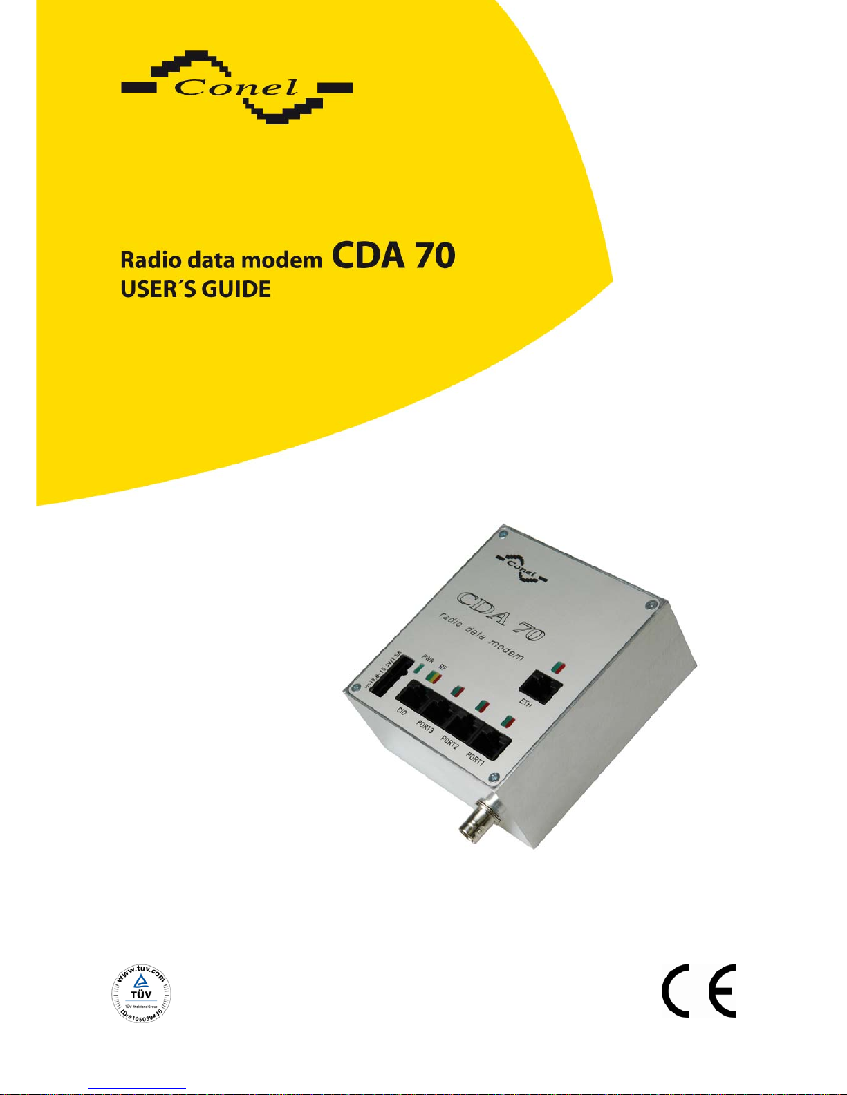
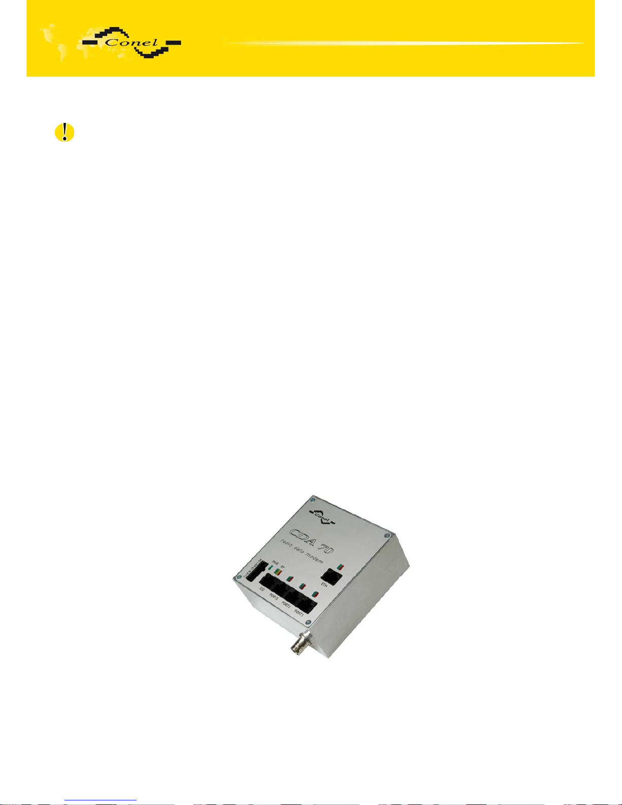
The CDA70 radio modem is a device for wireless data transmission. Communication
between two radio modems is a simplex one and is carried out on a single frequency. Modems
work in frequency band of 143 to 174 MHz (CDA70V) and 403 to 470 MHz (CDA70U).
Transmission rate is 21.7 kbit/sec when using the FFSK modulation and channel spacing 20
and 25 kHz or 10.8 kbit/sec when using channel spacing 12.5 kHz. Transmission rate is 10.8
kbit/sec when using the GMSK modulation and channel spacing 20 and 25 kHz or 5.4 kbit/sec
when using channel spacing 12.5 kHz. Transmission power output of the radio modem is
adjustable from 10 mW to 3 W for CDA70V and from 10 mW to 5 W for CDA70U.
The CDA70 radio data modem is controlled by a 32-bit communication processor
providing communication on the radio channel and individual interfaces. The CDA70 modem
has four serial data interfaces (communication ports) and one with direct attachment
of input/output peripherals for data collection and CIO technological process control. It is
possible to set transfer parameters and communication protocol separately for each port.
As a result, you may use the radio modem to communicate with various user interfaces using
different communication protocols on the serial interface.
The communication protocol used for communication between modems on the radio
channel provides for access of the modem to the radio channel, collision solving,
retranslations and other functions necessary for cooperation of modems within a radio data
network. It allows creating of a large network on a single radio channel and independent
operation of multiple radio networks on a single frequency. The radio data modem CDA-70 is
possible to use in combination with other modems of the system AGNES. Description
of the system AGNES is in reference [2].
2.2. Examples of possible applications
• Security systems
• Telematics
• Telemetry
• Vending and dispenser machines
2.3. Description of individual components
2.3.1. Radio component
Working frequency of the radio component is synthetizer-controlled separately for
reception and transmission. It is tuneable within a broad frequency band (see Technical
parameters table). Several levels of the radio module transmitter power output can be set
(from 10 mW to 5 W). The controlling microcomputer program controls setting of the working
frequency and transmitting power output. The radio module supplies the microcomputer
with information on the radio signal level being received (RSSI – Received Signal Strength
Indicator). This information is used for measuring of the signal strength between individual
nodes of the radio network.
Page 6

CDA70 MODEM DESCRIPTION
6
2.3.2. Modem component
The modem part converts digital bit flow from the microcomputer to the FFSK or GMSK
analogue modulation, which is brought to the transmitter of the radio data module. And vice
versa, it converts analogue signal from the receiver to digital bit flow to the microcomputer.
The modem part is designed on the basis of a CML integrated circuit.
2.3.3.
Microcomputer
The base of the radio data modem controlling microcomputer is represented by a 32-bit
processor with 1 MB of RAM, 512 kB of FLASH ROM and real time clock circuit with a back-up
power supply.
On one side, the microcomputer is connected to the radio data module via the modem
component; on the side of user interface, it is connected to circuits generating signals within
the RS232, RS485, M-BUS or Ethernet standard levels. The microcomputer provides for
connection of up to four user interfaces. All ports are terminated by RJ45 connectors marked
PORT1, PORT2, PORT3 and ETH. All RS232 ports are protected against overvoltage
incoming via data cable. If a device with RS485 interface is to be connected, a level converter
suitable for the appropriate application can be connected to the serial port. Different converters
will be used in case of connection on a short distance or in case galvanic separation is
necessary. The modem's microcomputer can be set for necessary control of the converter
(RS485). To each interface, a device with different communication protocol can be connected i.e. the microcomputer can also work as a converter of protocols between individual serial
ports. The wide range of radio modem functions can be set via any of RS232 communication
ports.
In addition, the microprocessor manages numerous functions of servicing
and installation purposes. Apart from other important information, the microcomputer memory
records data transmission statistics, strength of signals from individual radio modems,
statistics of communication on individual serial ports, power failures, voltage of backup power
source and temperature inside the radio data modem. See Service manual for description
of service functions.
Configuration of the CDA70 radio data modem is stored in the permanent FLASH ROM
memory. See the Configuration of radio modem chapter for description of its settings.
2.3.4.
Inputs and outputs for telemetry
As an option, customers may wish to install inputs and outputs for data collection
and controlling of technological processes in the radio modem. These signals are then led
to an RJ45 connector marked I/O. Five signals are led to this connector. Each of them can be
used either as input or output. Input is analogue 0 to 5V or digital with adjustable threshold.
The output is an open collector able to switch up to 500 mA. Reading and control of I/O signals
is possible both via the radio data network and from any serial RS232 interface. Two radio
data modems can make up a simple technology control, where changes on one modem input
signals can control remote output signals of the other modem and vice versa.
For multi-purpose usage, we supply an interface between the I/O connector
and the technology providing configurable voltage and current inputs, inputs for resistance
measurement (thermometers, barometers etc.), binary inputs with optical isolation and relay
Page 7

CDA70 MODEM DESCRIPTION
7
outputs. With the equipment you may establish simple telemetry at low cost, without the use
of industrial control automat.
2.3.5.
User interface protocols
For user interface, a range of standard protocols is implemented:
• AT modem
• PROFIBUS
• M-BUS
• MODBUS
• Asynchronous transparent line
• Transparent bus
• Sauter
• IWKA
• SBUS
• RADOM
• RDS
New protocols, currently not supported by the radio modem, can be implemented
according to the customer's needs.
Page 8
CDA70 MODEM DESCRIPTION
8
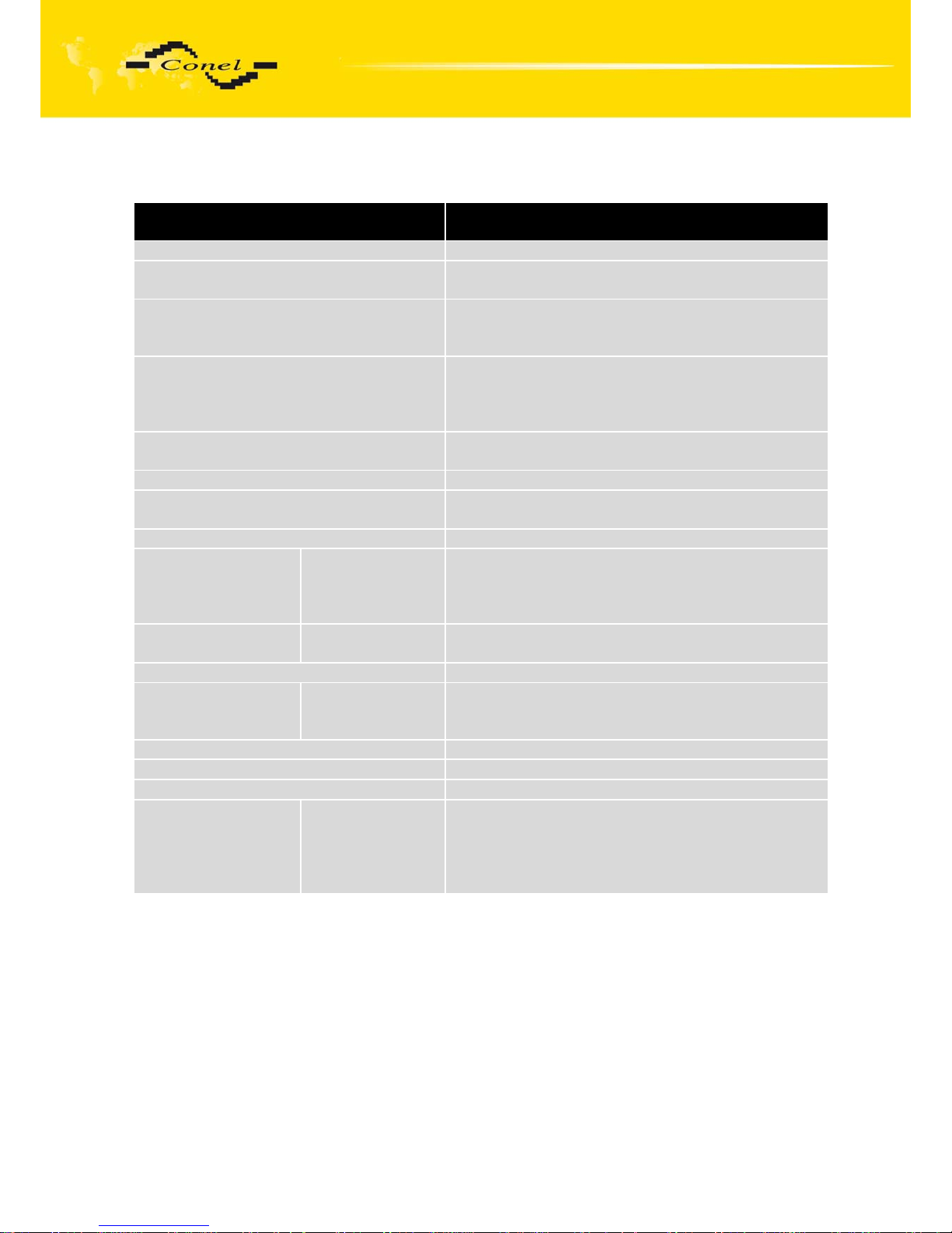
2.3.6. Technical parameters
Frequency band 143 – 174 MHz (CDA70V version)
403 – 470 MHz (CDA70U version)
Adjustment of working frequency program setting
Adjustment of working frequency of
receiver and transmitter
separate for each part
Adjustment of channel spacing program setting
12,5; 25 kHz (CDA70V version)
12,5; 20; 25 kHz (CDA70U version)
Output power program setting
0.5;1;2;3 W (CDA70V version)
0,01;0,05;0,1;0,25;0,5;1;2;3;4;5 W (CDA70U
version)
Receiver sensitivity for 10 dB SINAD <-111 dBm (12 dB SINAD) for channel 25/20 kHz
<-117 dBm (12 dB SINAD) for channel 12,5 kHz
Reception / transmission switching time < 4 msec
Maximum transmission rate 21.7 kbit/sec for channel spacing of 20 and 25 kHz
10.8 kbit/sec for channel spacing of 12.5 kHz
Type of modulation 4-FSK, GMSK
Radio modem
complies with
standards:
Radio parameters
EMC
Power safety
EN 300 113-1: V1.5.1
EN 300 113-2: V1.2.1
EN 301 489-5: V1.3.1
EN 60 950-1:2001
Temperature range Operation
Storage
-20 °C to +55 °C
-40 °C to +85 °C
Supply voltage (car dashboard) +10.8 to +15.6V DC
Current Reception
Transmission 1 W
Transmission 5 W
<200 mA
<900 mA
<1500 mA
Dimensions 43x104x98 mm (DIN35 attachment to board)
Weight 600g
Antenna connector BNC – 50 Ohm
User interface PORT1
PORT2
PORT3
ETHERNET
I/O
See. chapter 2.5.1
See. chapter 2.5.2
See. chapter 2.5.3
See. chapter 2.5.4
See. chapter 2.5.5
Page 9
CDA70 MODEM DESCRIPTION
9
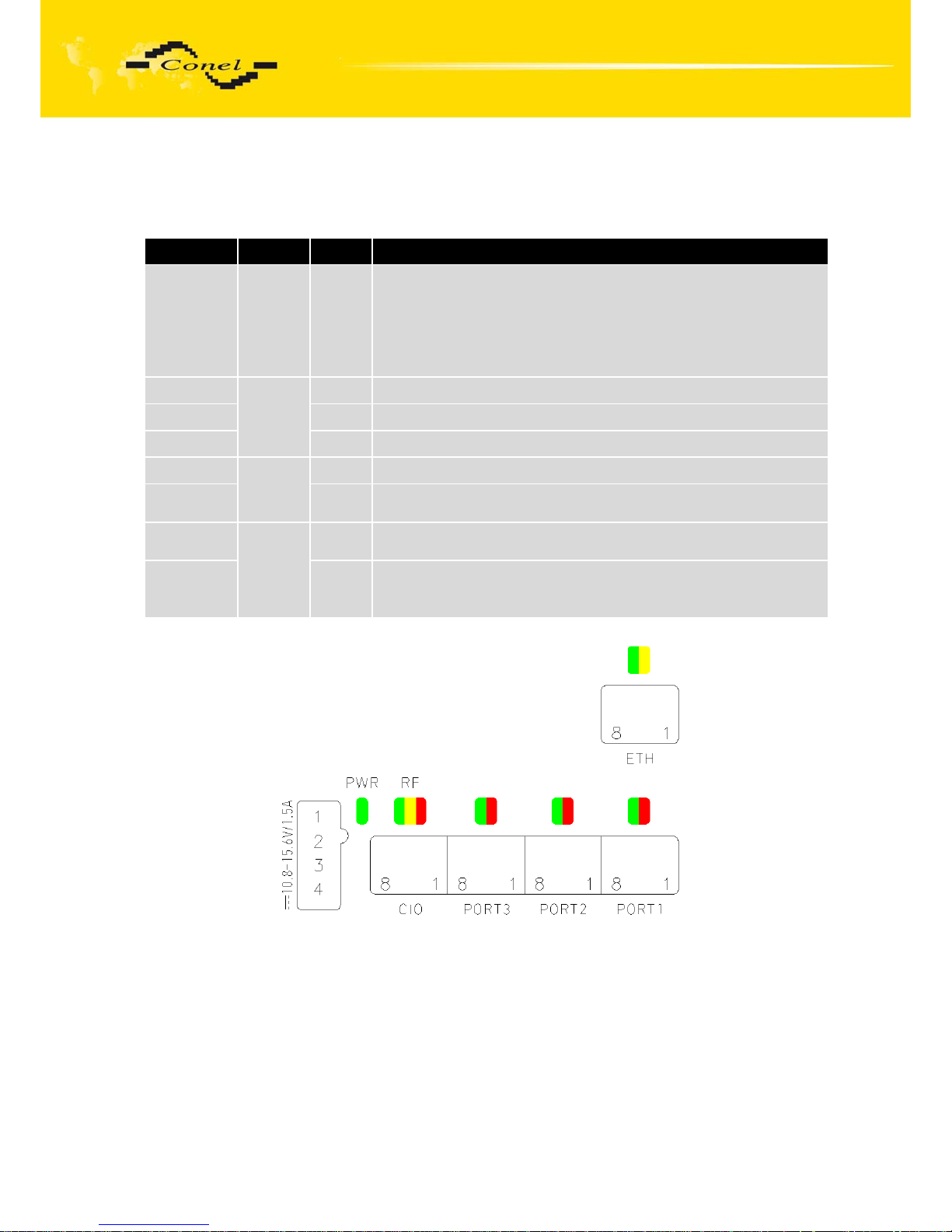
2.4. Radio modem status indication
Seven LED status indicators informing of the radio data modem status are located
on the front panel. They are arranged in three arrays:
Colour
Group
Meaning
GREEN PWR
Blinking 1:9…..……..proper function
Blinking 9:1…..……..RF monitoring
Permanently on ...... error
Permanently off ..... no power +12V
Double flashing …...data reception on VF channel,
level <-100dBm
RED
RF
TX
Modem is sending data to radio channel
YELLOW
RX
Receiving synchronisation or data from radio channel
GREEN
DATA
Data received from radio channel are intended for this modem
RED
PORT1-
PORT3
TX Transmission to one of ports (PORT1 ... PORT3)
GREEN DATA
Modem is receiving correct data from one of ports
(PORT1 .. PORT3)
YELLOW
ETH
LINK
Permanently on ........... selected 100 Mbit/s
Permanently off ........... selected 10 Mbit/s
GREEN ACT
Permanently on............ the network cable is connected
Blinking ……………......data transmission
Permanently off............ the network cable is not connected
2.5. User interfaces (connectors)
The rear panel of the radio modem contains up five RJ45 connectors. Four data
interfaces are labelled PORT1, PORT2, PORT3 and ETH. The fifth connector with I/O label is
intended for direct connection of inputs/outputs for data collection and technology control.
The technology control and data collection can be supplied as an optional accessory upon
request of the customer.
Page 10
CDA70 MODEM DESCRIPTION
10
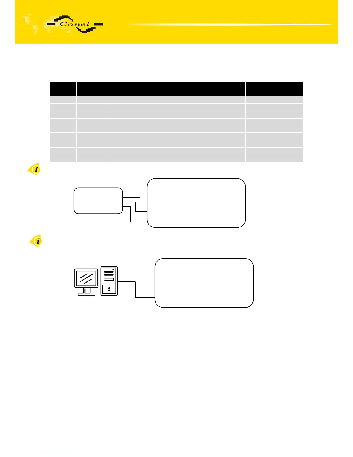
2.5.1. Connection of PORT1, PORT2 and PORT3 connectors (RS232)
(RS232 – DCE – Data Communication Equipment)
Pin
number
Signal
mark
Description Data flow direction
1 RTS Request To Send Input
2 CTS Clear To Send Output
3 DTR Data Terminal Ready Input
4 DSR Data Set Ready - connected to +12V through
1k8 Ohm resistor
Output
5 GND GROUND - signal ground
6 RXD Receive Data Output
7 CD Carrier Detect Output
8 TXD Transmit Data Input
Circuit example of the meter with modem CDA70:
Circuit example of the PC with
modem CDA70:
• the cable KD2 is connected to serial PC port (example COM1)
Modem CDA70
PWR
CIO
PORT3
PORT2
PORT1 ETH
Cable KD-2
Pin 1 – RTS
Pin 2 – CTS
Pin 3 – DTR
Pin 4 – DSR
Pin 5 – GND
Pin 6 – RXD
Pin 7 – CD
Pin 8 – TXD
Modem CDA70
Meter
GND
RXD
TXD
Page 11
CDA70 MODEM DESCRIPTION
11
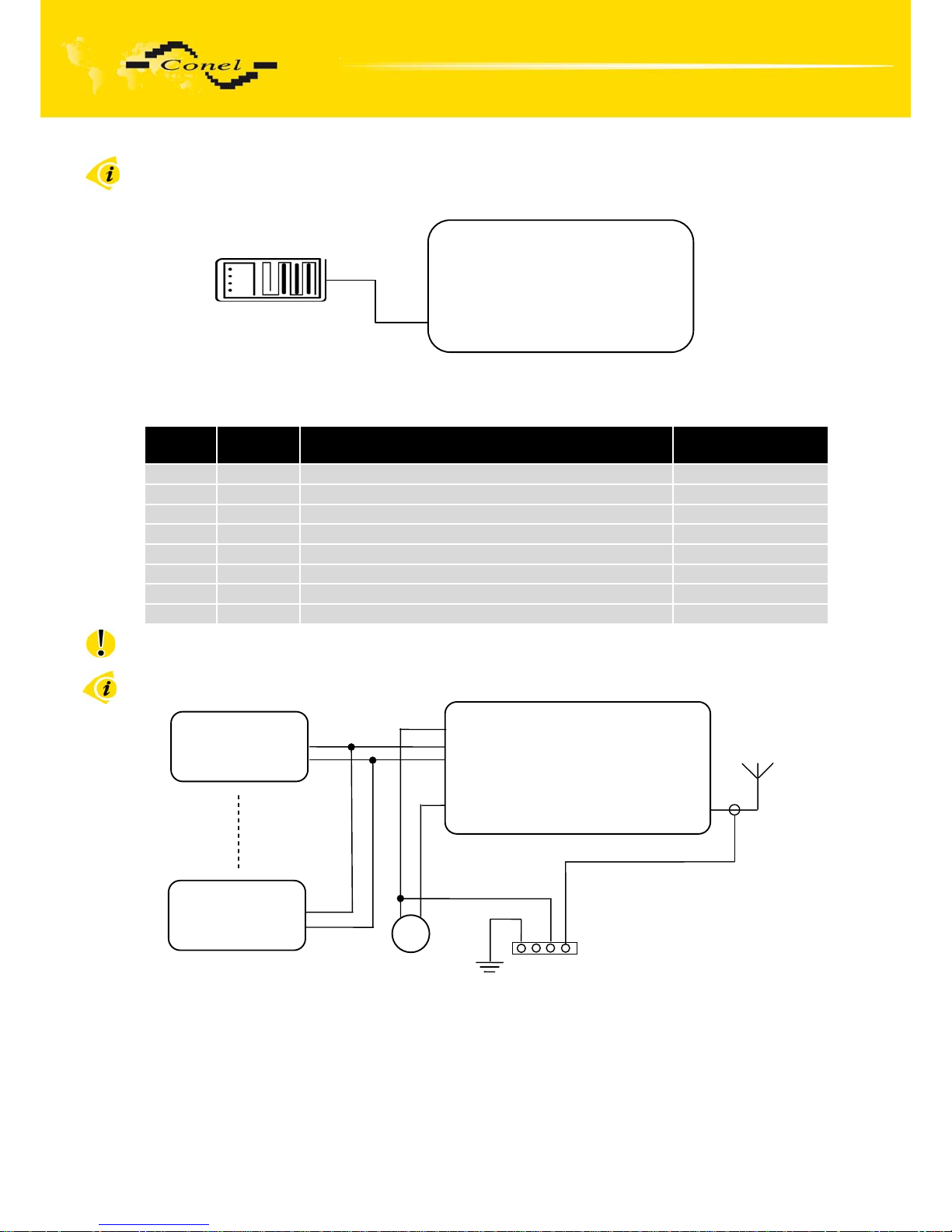
Circuit example of the RS232 equipment with modem CDA70:
2.5.2.
Connection of PORT1 connectors (M-BUS)
Panel socket RJ45
Pin
number
Signal
mark
Description Data flow direction
1 SGND Signal and supply ground
2 SGND Signal and supply ground
3 TxRx- M-BUS B (-) Input/Output
4 TxRx+ M-BUS A (+) Input/Output
5 TxRx- M-BUS B (-) Input/Output
6 TxRx+ M-BUS A (+) Input/Output
7 +12V EXT External power supply +10,8 ÷ +15,6V
8 +12V EXT External power supply +10,8 ÷ +15,6V
ATTENTION! External supply is for converter M-BUS!
The converter must have external power supply because of galvanic separated.
Circuit example of the meter with modem CDA70 with data cable length less than 10 m:
DC
Meter
SGND
MBUS (-)
MBUS (+)
Meter
SGND
MBUS (-)
MBUS (+)
Modem CDA70
Pin 1 – SGND
Pin 2 – SGND
Pin 3 – MBUS (-)
Pin 4 – MBUS (+)
Pin 5 – MBUS (-)
Pin 6 – MBUS (+)
Pin 7 – +12V EXT
Pin 8 – +12V EXT
+
Modem CDA70
Cable KD-2
PWR
CIO
PORT3
PORT2
PORT1 ETH
Page 12
CDA70 MODEM DESCRIPTION
12
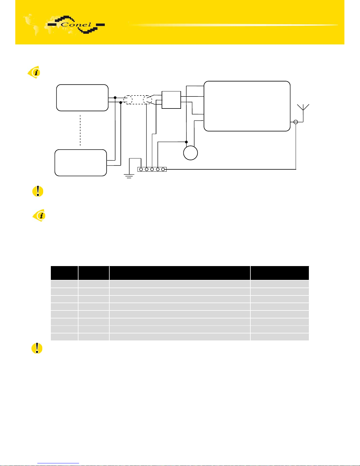
Circuit example of the meter with modem CDA70 with data cable length more than 10 m:
M-BUS data cable more than 10 m it is need to use over-voltage protection on CDA 70
modem side!
External or internal power supply of expansion port M-BUS it is can evoke by wiring
of the jumper. For details see chapter 2.8.
2.5.3. Connection of PORT2 connectors (RS485G)
Panel socket RJ45
Pin
number
Signal
mark
Description Data flow direction
1 GND Signal and supply ground
2 GND Signal and supply ground
3 TxRx- RS485 B (-) Input/Output
4 TxRx+ RS485 A (+) Input/Output
5 TxRx- RS485 B (-) Input/Output
6 TxRx+ RS485 A (+) Input/Output
7 +12V EXT External power supply +10,8 ÷ +15,6V
8 +12V EXT External power supply +10,8 ÷ +15,6V
ATTENTION! External supply is for converter RS485G!
The converter must have external power supply because of galvanic separated.
DC
Meter
SGND
MBUS (-)
MBUS (+)
Meter
SGND
MBUS (-)
MBUS (+)
Modem CDA70
Pin 1 – SGND
Pin 2 – SGND
Pin 3 – MBUS (-)
Pin 4 – MBUS (+)
Pin 5 – MBUS (-)
Pin 6 – MBUS (+)
Pin 7 – +12V EXT
Pin 8 – +12V EXT
+
1X
2X
1Y
2Y
OVPM-21
Page 13
CDA70 MODEM DESCRIPTION
13
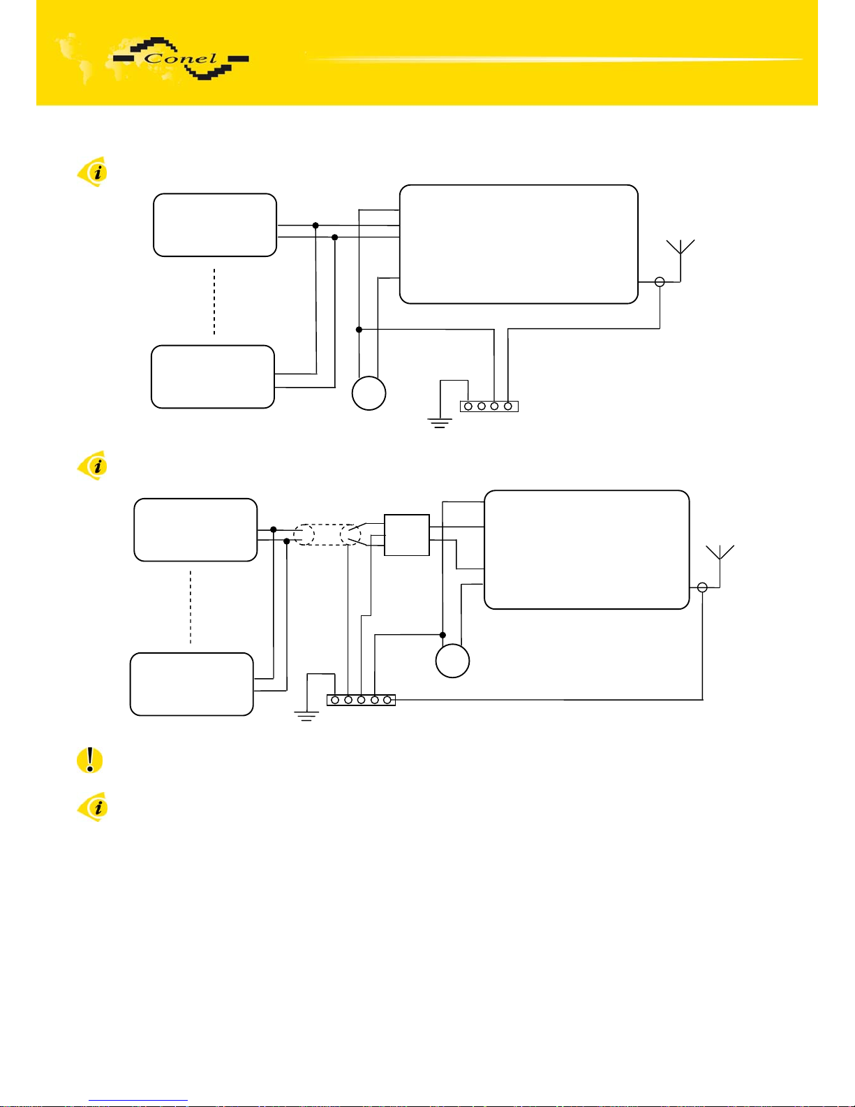
Circuit example of the meter with modem CDA70 with data length less than 10 m:
Circuit example of the meter with modem CDA70 with data length more than 10 m:
At RS485 data cable more than 10 m it is need to use over-voltage protection on
CDA 70 modem side!
External or internal power supply of expansion port RS485 it is can evoke by wiring
of the jumpers. For details see chapter 2.8.
DC
Meter
SGND
RS485 (-)
RS485 (+)
Meter
SGND
RS485 (-)
RS485 (+)
Modem CDA70
Pin 1 – SGND
Pin 2 – SGND
Pin 3 – RS485 (-)
Pin 4 – RS485 (+)
Pin 5 – RS485 (-)
Pin 6 – RS485 (+)
Pin 7 – +12V EXT
Pin 8 – +12V EXT
+
1X
2X
1Y
2Y
OVPM-21
DC
Meter
SGND
RS485 (-)
RS485(+)
Meter
SGND
RS485 (-)
RS485(+)
Modem CDA70
Pin 1 – SGND
Pin 2 – SGND
Pin 3 – RS485 (-)
Pin 4 – RS485 (+)
Pin 5 – RS485 (-)
Pin 6 – RS485 (+)
Pin 7 – +12V EXT
Pin 8 – +12V EXT
+
Page 14
CDA70 MODEM DESCRIPTION
14
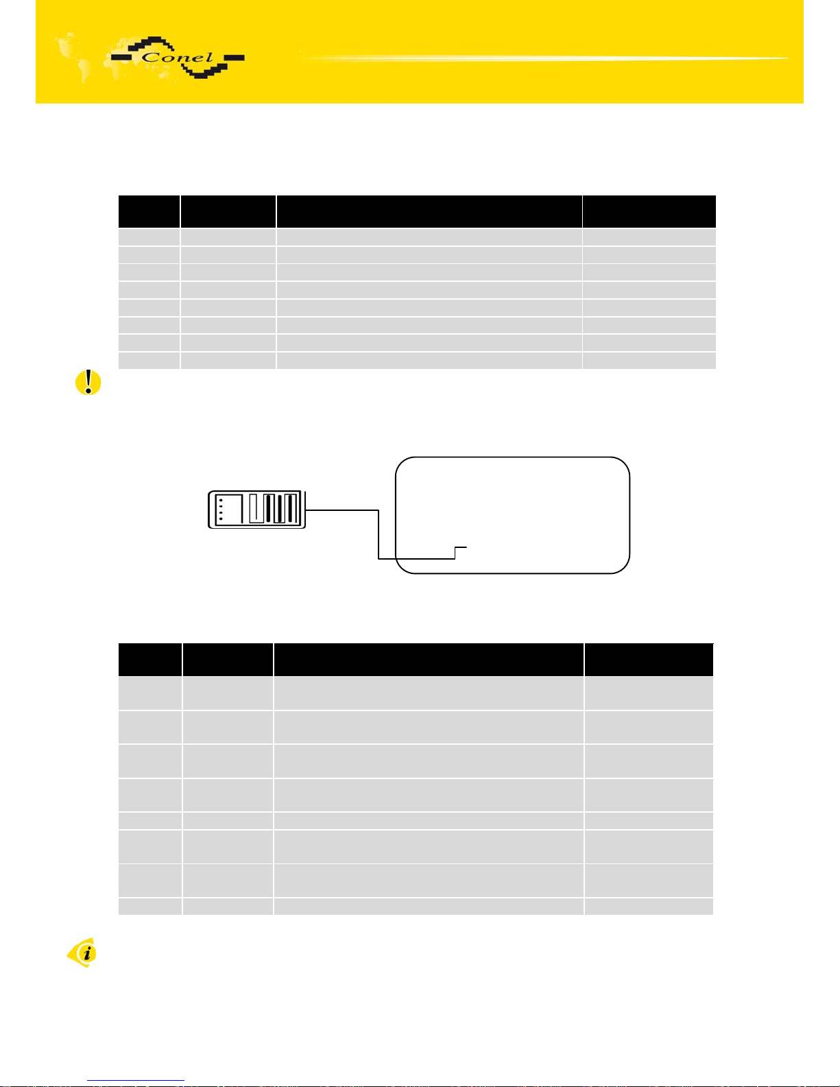
2.5.4. Connection of ETH connectors (ETHERNET)
Panel socket RJ45
Pin
number
Signal mark Description
Data flow
direction
1 TXD+ Transmit Data Input/Output
2 TXD- Transmit Data Input/Output
3 RXD+ Receive Data Input/Output
4 DNC ---
5 DNC ---
6 RXD- Receive Data Input/Output
7 DNC ---
8 DNC ---
ATTENTION! Port ETH is not with POE (Power Over Ethernet) compatible!
Circuit example of the CDA70 with
to equipment with Ethernet:
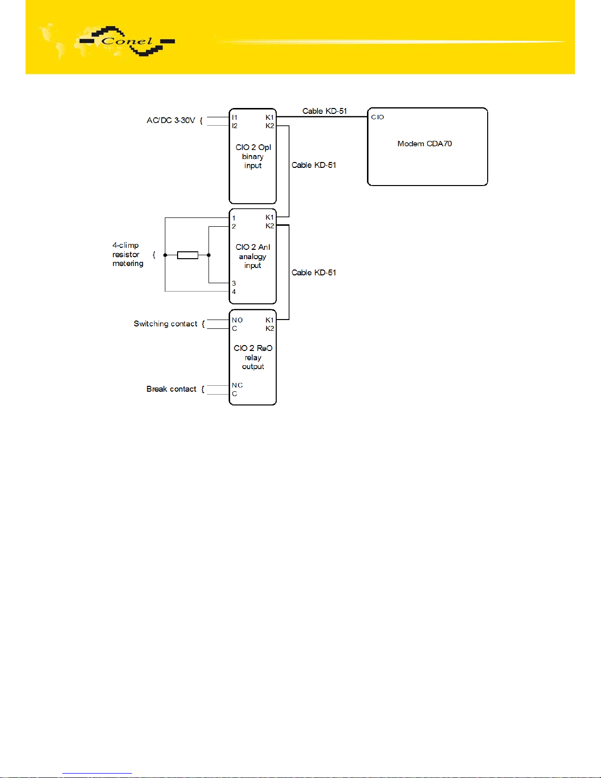
2.5.5. Connection of I/O connector
Panel socket RJ45
Pin
number
Signal mark Description Data flow
direction
1 I/O 5 Input/Output - analogue or binary input or binary
output (open collector)
Input/Output
2 I/O 4 Input/Output - analogue or binary input or binary
output (open collector)
Input/Output
3 I/O 3 Input/Output - analogue or binary input or binary
output (open collector)
Input/Output
4 +12V Output + 12V for supply of other circuits
(connected directly to modem supply)
Output
5 GND Signal and supply ground
6 I/O 2 Input/Output - analogue or binary input or binary
output (open collector)
Input/Output
7 I/O 1 Input/Output - analogue or binary input or binary
output (open collector)
Input/Output
8 Service For servicing purposes only Input/Output
Circuit example of the meter with modem CDA70:
Modem CDA70
UTP cable
PWR
CIO
PORT3
PORT2
PORT1 ETH
Page 15
CDA70 MODEM DESCRIPTION
15
Page 16
CDA70 MODEM DESCRIPTION
16
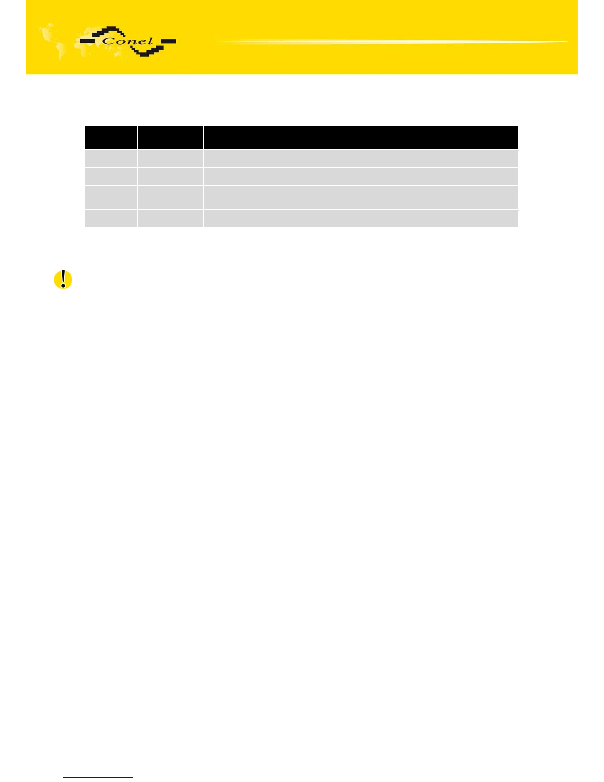
2.5.6. Power supply connector (PWDD)
Pin
number
Signal mark Description
1 +12V Positive pole of supply voltage
2 GND Negative pole of supply voltage
3 PWRSV Open collector output (Power Save) for controlling of supply voltage
of the whole radio modem, see chapter 3.4
4 IN1 Input -power failure supervision. (Analogue input 0-16V)
On the power supply connector it is possible to use the signal INAC (NAP230) for
present AC voltage monitoring for power supply (it can be functional only in case of supply
accumulator backup).
Beware, on INAC (NAP230) input it isn't possible connect link voltage 230 V direct!
Page 17
CDA70 MODEM DESCRIPTION
17
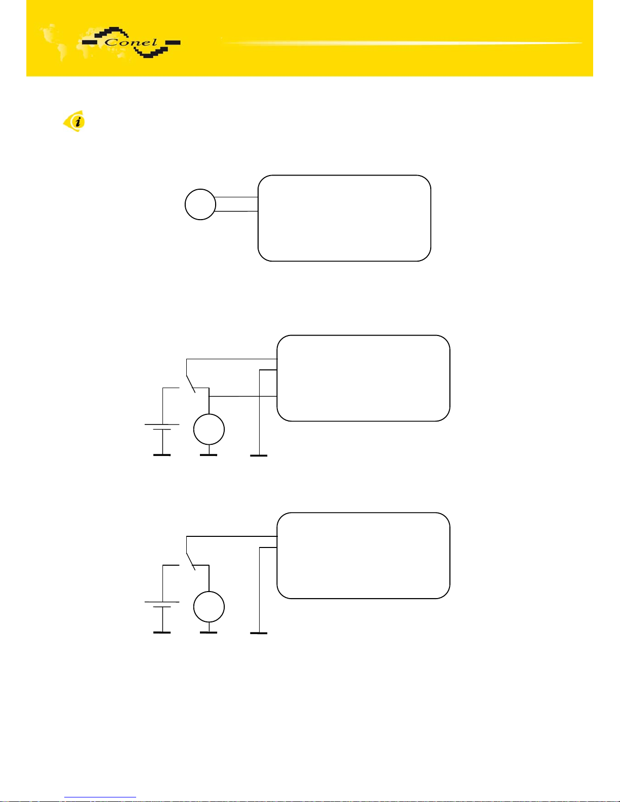
Circuit example:
DC supply
DC supply with backup battery with present supply monitoring
DC supply with backup battery without present supply monitoring
Modem CDA70
DC
+
Pin 1 – +12V
Pin 2 – GND
Pin 3 – PWRSV
Pin 4 – INAC
Modem CDA70
DC
+
Pin 1 – +12V
Pin 2 – GND
Pin 3 – PWRSV
Pin 4 – INAC
Pin 1 – +12V
Pin 2 – GND
Pin 3 – PWRSV
Pin 4 – INAC
Modem CDA70
DC
+
Page 18
CDA70 MODEM DESCRIPTION
18
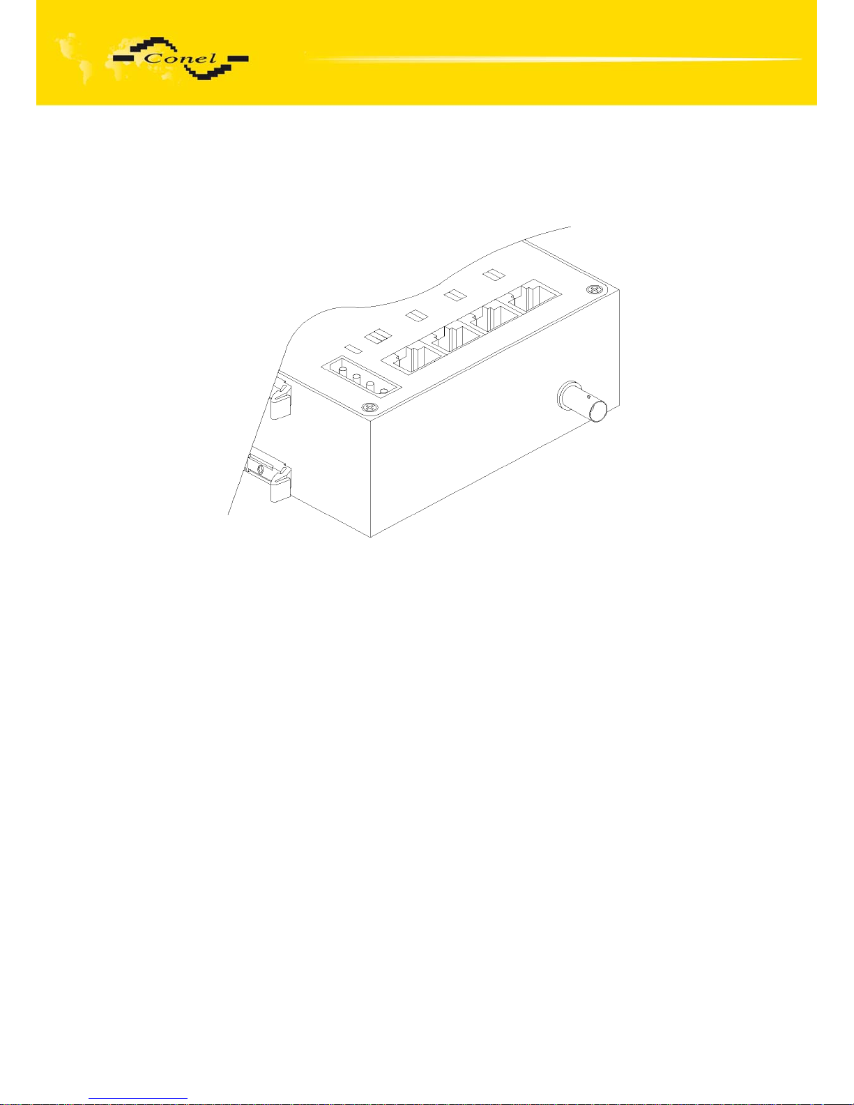
2.6. Antenna connection
Antenna is connected to the radio data modem via a BNC connector located
on the side panel.
2.7. Power supply
Supply voltage working range of the radio modem is +10.8 to +15.6V dc (12V
accumulator). Current consumption during reception is 190 mA. During transmission, current
consumption depends on the transmission output (1500 mA for 5 W). For proper function, it is
necessary that the power source can supply peak current of 2000mA.
Page 19
CDA70 MODEM DESCRIPTION
19
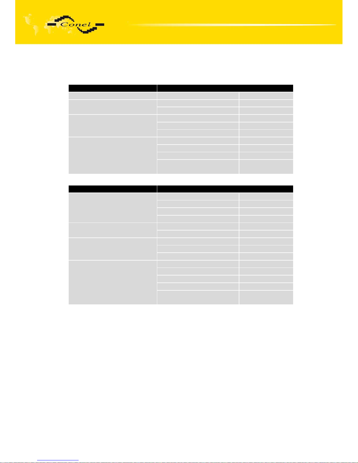
2.8. Ports technical specifications
• RS232
Name of product RS232
Power supply Internal ....
Environment
Operating temperature -20 .. +55 C
Storage temperature -20 .. +85 C
Standards
Emission EN 55022/B
Immunity ETS 300 342
Safety EN 60950
RS232 specifications
(EN 1434)
Max. operating bus current 15 mA
Max. bit rate 230400 bps
Max. overvoltage ±30 V
Max. total cable length
(300Bd, 200nF/km)
20 m
• RS485
Name of product RS485
Power supply External 10,8 .. 15,6 V
Internal ....
Supply power Max. 30 W
Supply current Max. 250 mA
Environment
Operating temperature -20 .. +55 C
Storage temperature -20 .. +85 C
Standards
Emission EN 55022/B
Immunity ETS 300 342
Safety EN 60950
RS485 specifications
(EN 1434)
Max. devices (each 1,5 mA) 256
Max. bit rate 38400 bps
Overload detection 250 mA
Short circuit strength Permanent
Max. total cable length
(300Bd, 200nF/km)
1200 m
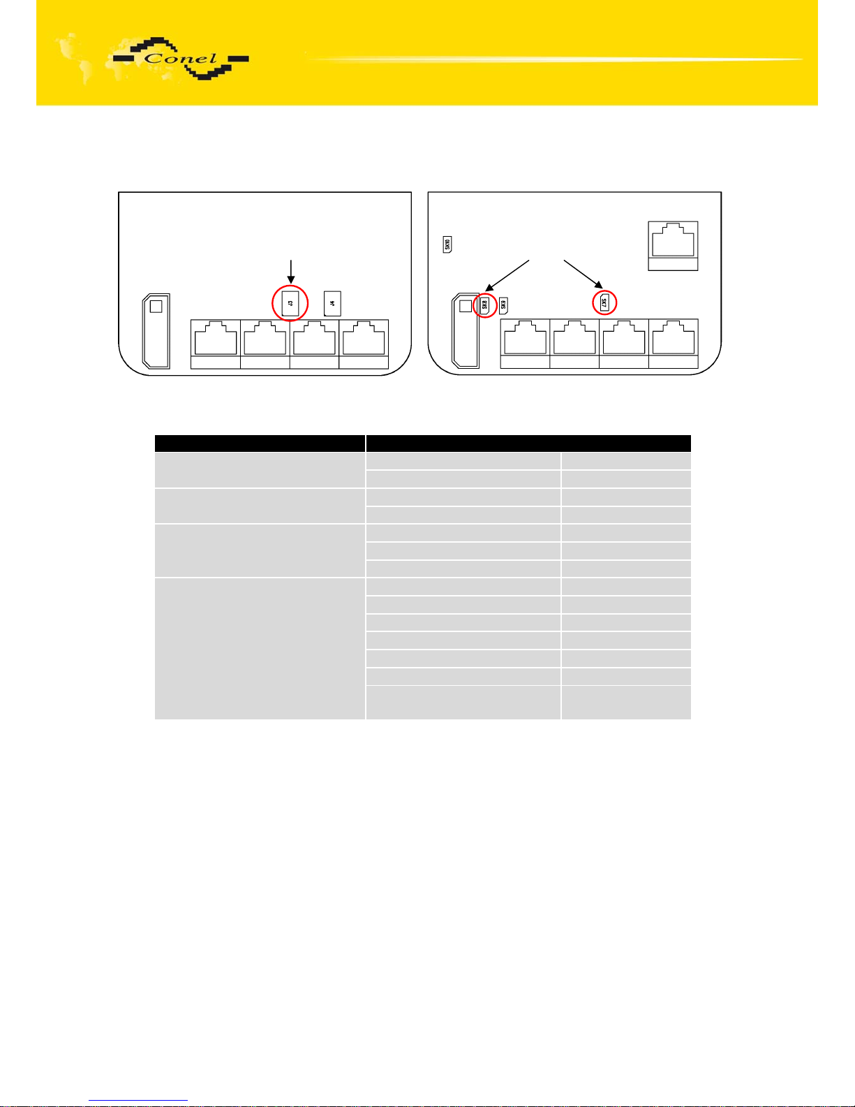
RS485 port power supply for CDA-70-U(V)-4M version
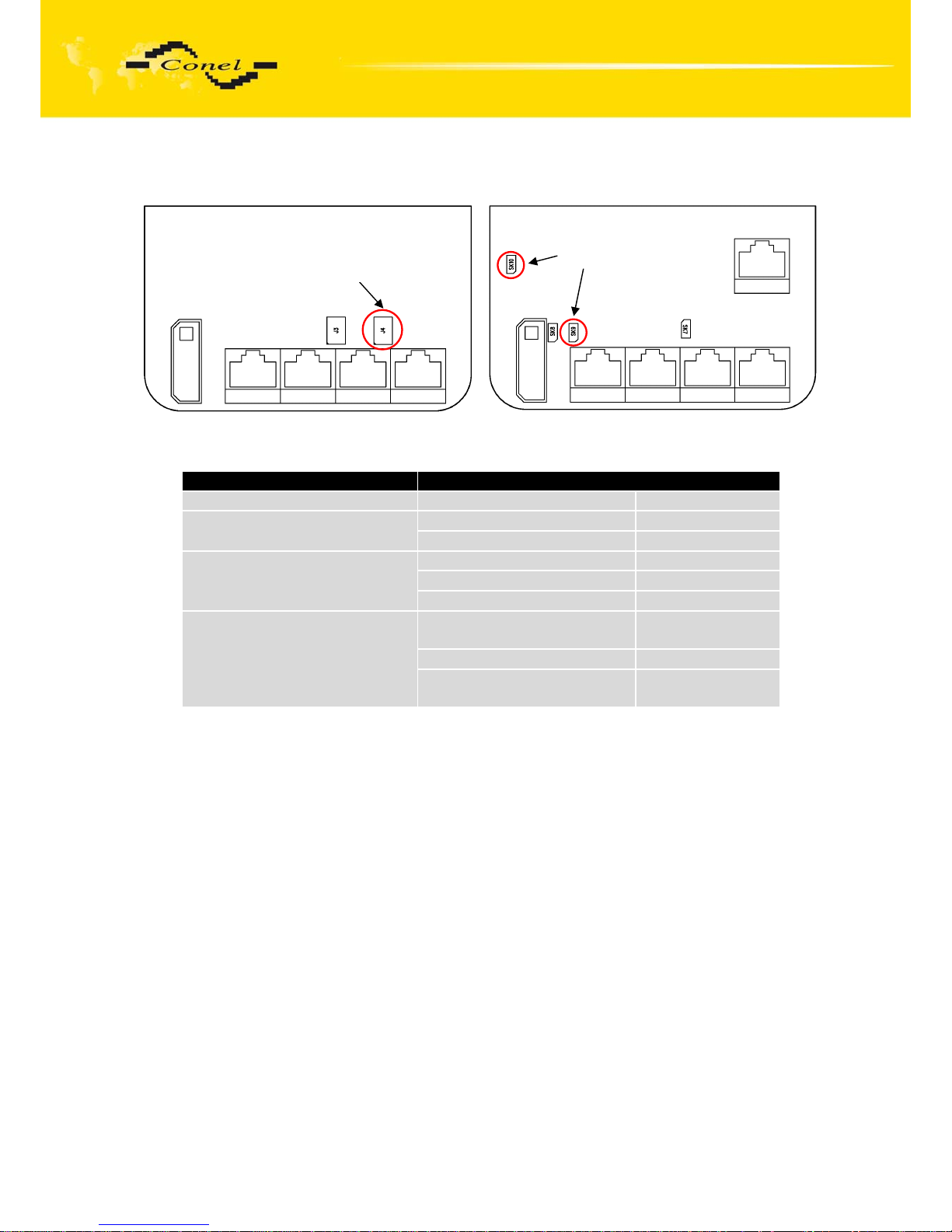
External or internal power supply of expansion port RS485 it is can evoke by wiring
of the jumper J3. If it is necessitated external power supply of module, it must be
disconnection jumper J3. Internal power supply is evoking of connection jumper J3. Jumpers
are placement them to a picture below. We recommended internal power supply only in the
event of, that it is not possible ensure external power supply. If it is choose internal power
supply, converter RS485 is not galvanic separated.
RS485 port power supply for CDA-70-U(V)-EM version
External or internal power supply of expansion port RS485 it is can evoke by wiring
of the jumpers SK7 and SK8. If it is necessitated external power supply of module, it must be
disconnection jumpers SK7 and SK8. Internal power supply is evoking of connection jumpers
SK7 and SK8. Jumpers are placement them to a picture below. We recommended internal
power supply only in the event of, that it is not possible ensure external power supply. If it is
choose internal power supply, converter RS485 is not galvanic separated
Page 20
CDA70 MODEM DESCRIPTION
20
Connection of the jumpers:
• M-BUS
Name of port M-BUS
Power supply Voltage 10,8 .. 15,6 V
Supply power Max. 30 W
Environment
Operating temperature -20 .. +55 C
Storage temperature -20 .. +85 C
Standards
Emission EN 55022/B
Immunity ETS 300 342
Safety EN 60950
M-Bus specifications
(EN 1434)
Max. devices (each 1,5 mA) 30
Max. operating bus current 60 mA
Overload detection 100 mA
Short circuit strength Permanent
Bus voltage mark 36 .. 43 V
Bus voltage space 24 .. 31 V
Max. total cable length
(300Bd, 200nF/km)
1000 m
M-BUS port power supply for CDA-70-U(V)-4M version
External or internal power supply of expansion port M-BUS it is can evoke by wiring
of the jumper J4. If it is necessitated external power supply of module, it must be
disconnection jumper J4. Internal power supply is evoking of connection jumper J4. Jumpers
are placement them to a picture below. We recommended internal power supply only in the
event of, that it is not possible ensure external power supply. If it is choose internal power
supply, converter M-BUS is not galvanic separated.
M-BUS port power supply for CDA-70-U(V)-EM version
External or internal power supply of expansion port M-BUS it is can evoke by wiring
of the jumpers SK9 and SK10. If it is necessitated external power supply of module, it must be
disconnection jumpers SK9 and SK10. Internal power supply is evoking of connection jumpers
SK9 and SK10. Jumpers are placement them to a picture below. We recommended internal
power supply only in the event of, that it is not possible ensure external power supply. If it is
choose internal power supply, converter M-BUS is not galvanic separated
CDA-70-U(V)-4M version
Jumper J3
CDA-70-U(V)-EM version
Jumpers SK7 and SK8
Page 21
CDA70 MODEM DESCRIPTION
21
Connection of the jumpers:
• Ethernet
Port ETH
Power supply Internal ...
Environment
Operating temperature -20 .. +55 C
Storage temperature -20 .. +85 C
Standards
Emission EN 55022/B
Immunity ETS 300 342
Safety EN 60950
Ethernet specification Max. virtual communicate
channels number
6
Max. bit rate 100 Mbps
Max. total cable length
(300Bd, 200nF/km)
100 m
CDA-70-U(V)-EM version
Jumpers SK9 a SK10
CDA-70-U(V)-4M version
Jumper J4
Page 22
CDA70 MODEM DESCRIPTION
22
2.9. Configuration of radio modem
The Radwin configuration program [1] has been designed to set up the CDA70 radio
data modem. The software is created for MS WINDOWS NT/98/ME/2000/XP/Vista platforms.
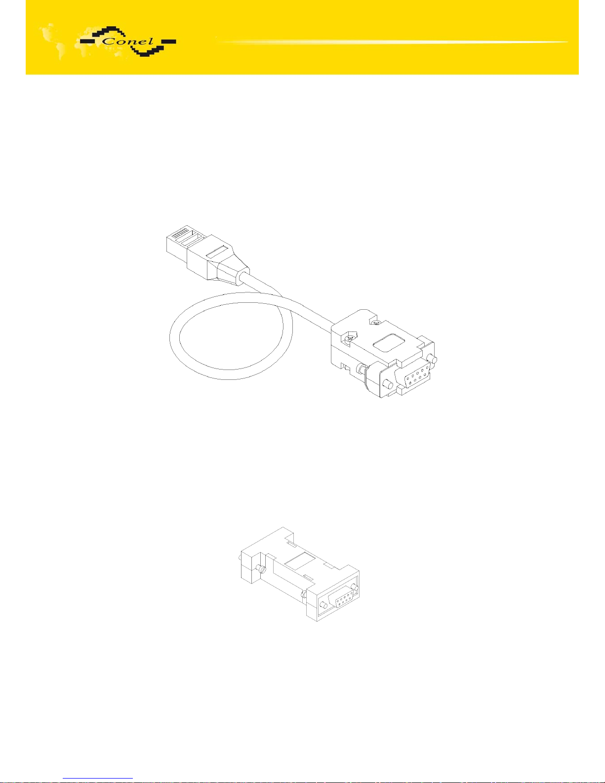
See User manual - Radwin software for description of the software. A service cable
is designated to connect the modem with a PC. After the service cable is connected to any
of the three RS232 serial ports and the service SW runs on the connected PC, it is possible to
execute not only all the needed radio modem settings but service interventions in the radio
data network as well.
Data cable KD-2
2.10. Service cable
CDA70 - PC connection cable with DCR and GND signals connected at 100 Ohm. It is
made from normal data cable by adding service interconnection. It is necessary to
interconnect all eight signals between CDA 70 and PC. See description of the RJ45 connector
in chapter 2.5.1.
Service interconnection to the data cable
Page 23

CDA70 MODEM DESCRIPTION
23
2.11. Accessories
1. Power supply connector for a power supply cable
2. Three RJ45 connectors to complete the data cable by snapping to the cable.
3. Compliance certificate
4. Complaint procedure
5. Warranty
2.12. Additional accessories
1. CIO-ReO-2 – expansion module with relay output
2. CIO-OpI-2 – expansion module with binary input
3. CIO-AnI-2 – expansion module with analogy input
4. KD-51 cable for CIO modules connection
Page 24
CDA70 MODEM DESCRIPTION
24
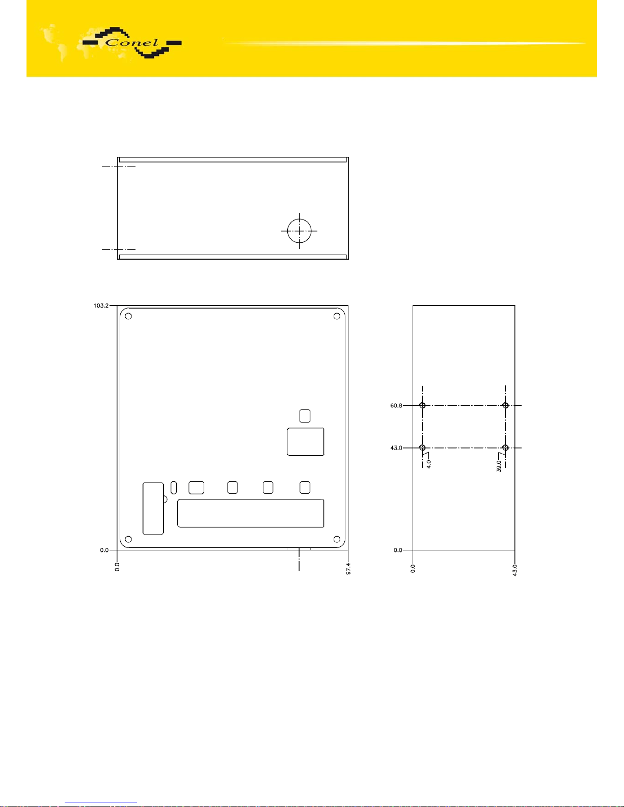
2.13. Mechanical drawing of CDA70 and recommendations for montage
For the majority of applications with a built-in modem in a switch board it is possible to
recognize two sorts of environments:
• nonpublic and industry environment of low voltage with high interference,
• public environment of low voltage without high interference.
For both of these environments it is possible to mount modems to the switch board,
which it doesn't need to have no examination immunity or issues in connection with EMC
according to EN 60439-1+A1.
Page 25
CDA70 MODEM DESCRIPTION
25
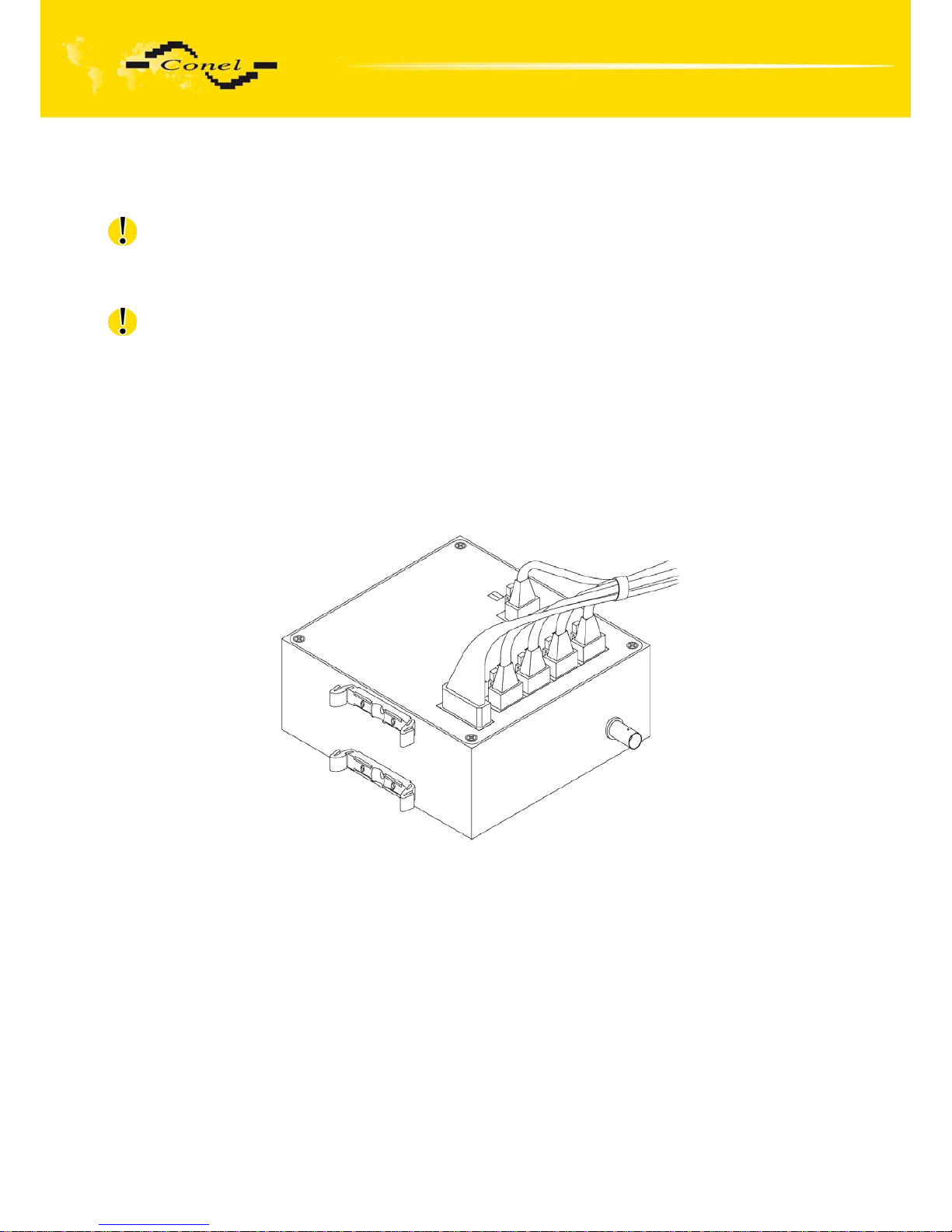
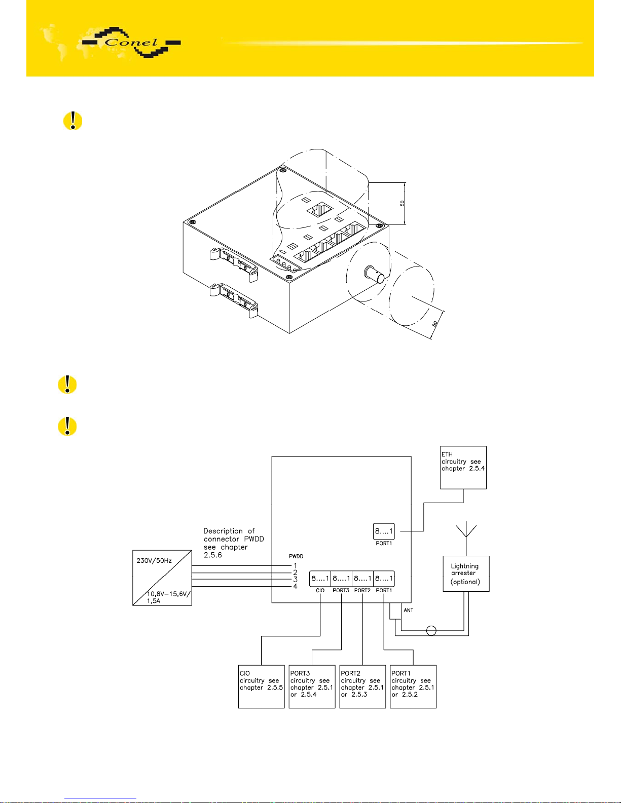
For compliance of EN 60439 - 1 + A1 specification it is necessary observe next
assembly of the modem to the switch - board:
• round antenna we recommend to observe a distance of 6 cm from cables and metal
surfaces on every side according to the next picture due to the elimination
of interference, while using an external antenna except for the switch-board it is
necessary to fit a lightening conductor,
• for single cables we recommend to bind the bunch according to the following picture,
for this use we recommend:
length of the bunch (combination of power supply and data cables) can
be maximum 1,5 m, if length of data cables exceeds 1,5 m or in the
event of, the cable leads towards the switch - board, we recommend to
use fit over – voltage protectors (surge suppressors),
with data cables they mustn't carry cable with reticular tension
~ 230 V/50 Hz,
all signals to sensors must be twisted pair.
Page 26
CDA70 MODEM DESCRIPTION
26
• sufficient space must be left before individual connectors for handling of cables,
• for correct function of the modem we recommend to use in switch - board earth-
bonding distribution frame for grounding of power supply of modem, data cables and
antenna,
• the circuit diagram of modem is on the following pictures.
Page 27
CDA70 MODEM DESCRIPTION
27
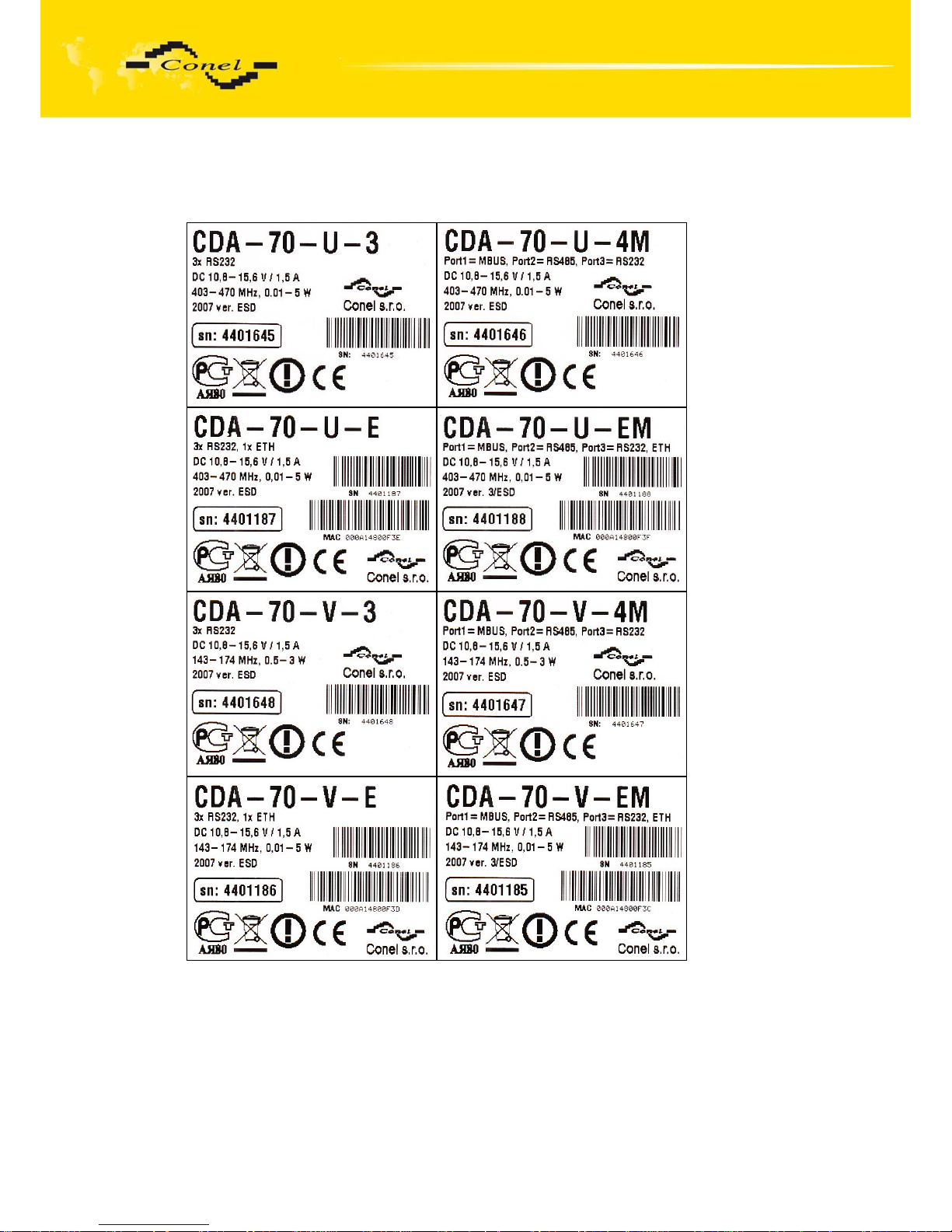
2.14. Product marking
Marking
Antenna
connector
Power supply Other
CDA-70-XX-YY BNC +10,8 to 15,6 V DC CIO
XX – frequency band U
V
403 to 470 MHz
143 to 174 MHz
YY – port
configuration
3
4M
E
EM
C
4
3x RS232
1x M-BUS + 1x RS485 + 1x RS232
1x Ethernet + 3 x RS232
1x Ethernet + 1x M-BUS + 1x RS485 + 1x RS232
1x CAN
1x RS232 + 2x RS485
Example: CDA-70-U-3 is radiomodem for band 403-470 MHz with 3x RS232.
Page 28
CDA70 MODEM DESCRIPTION
28
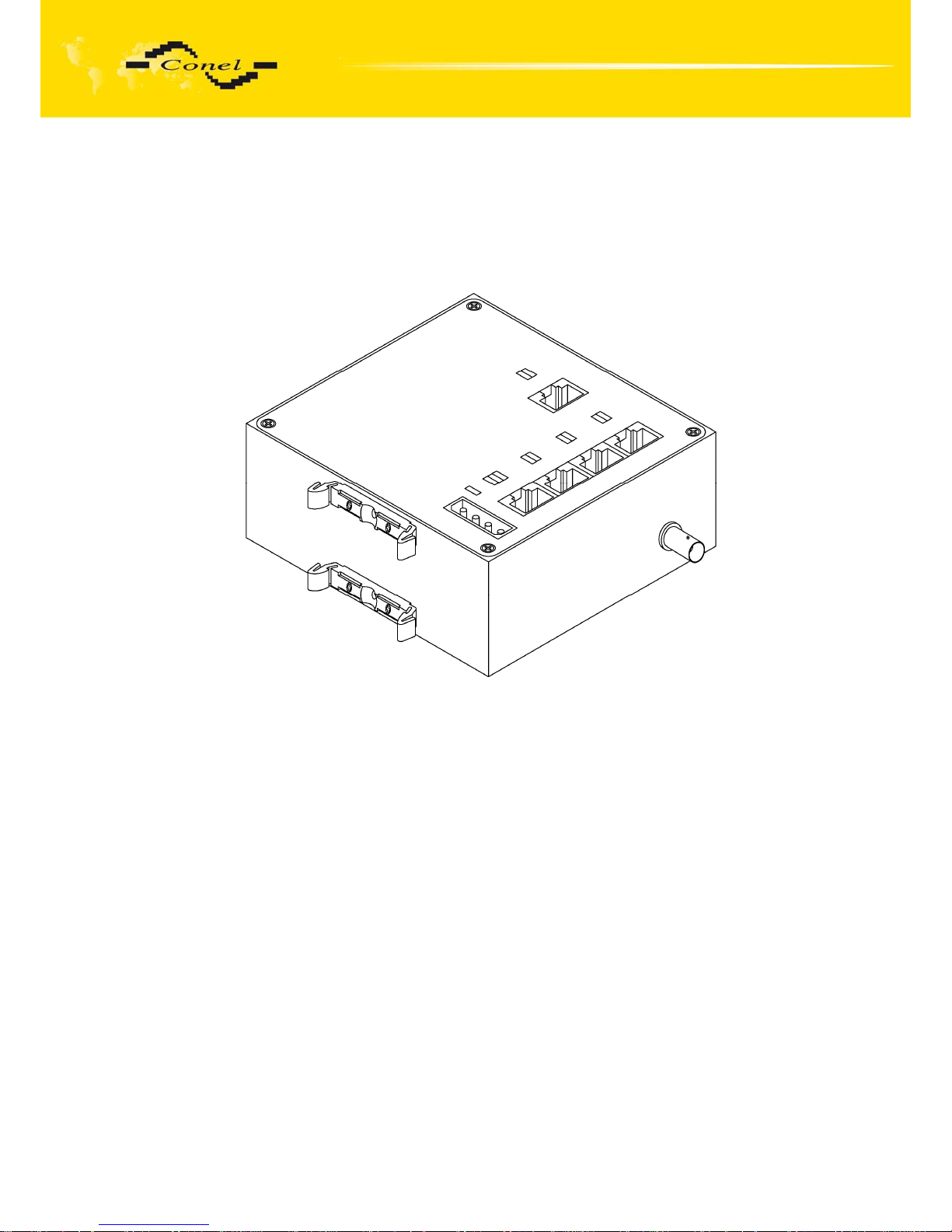
2.15. Assembly procedure
The radio data modem CDA70 is designed as a standard for:
1. DIN 35 mm rail assembly using plastic grips.
Page 29
CDA70 MODEM DESCRIPTION
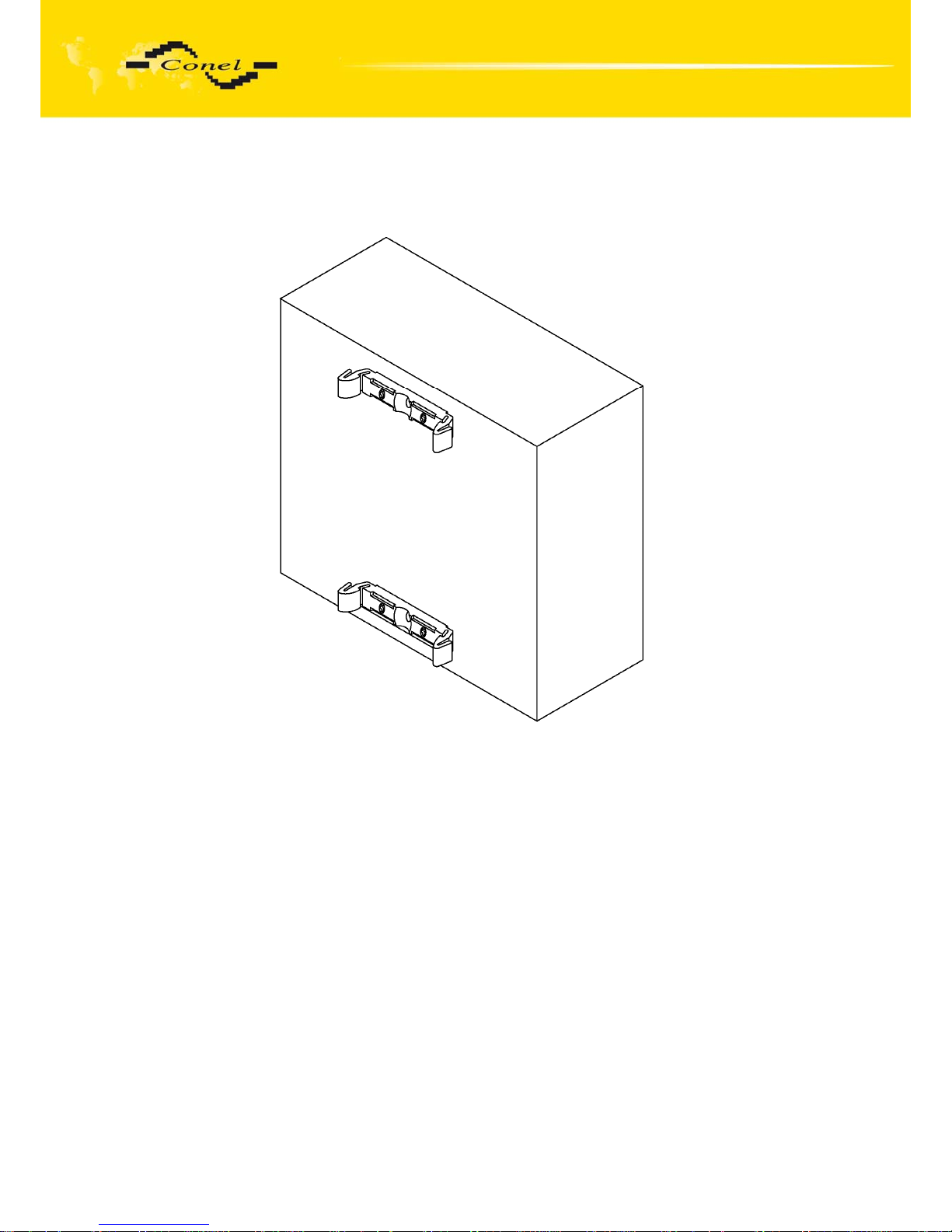
29
2. DIN 35 mm rail assembly using plastic grips from back side.
Page 30
CDA70 MODEM DESCRIPTION
30
2.16. Product label
Page 31
CDA70 MODEM DESCRIPTION
31
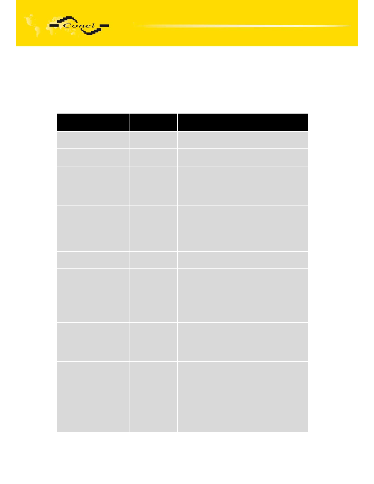
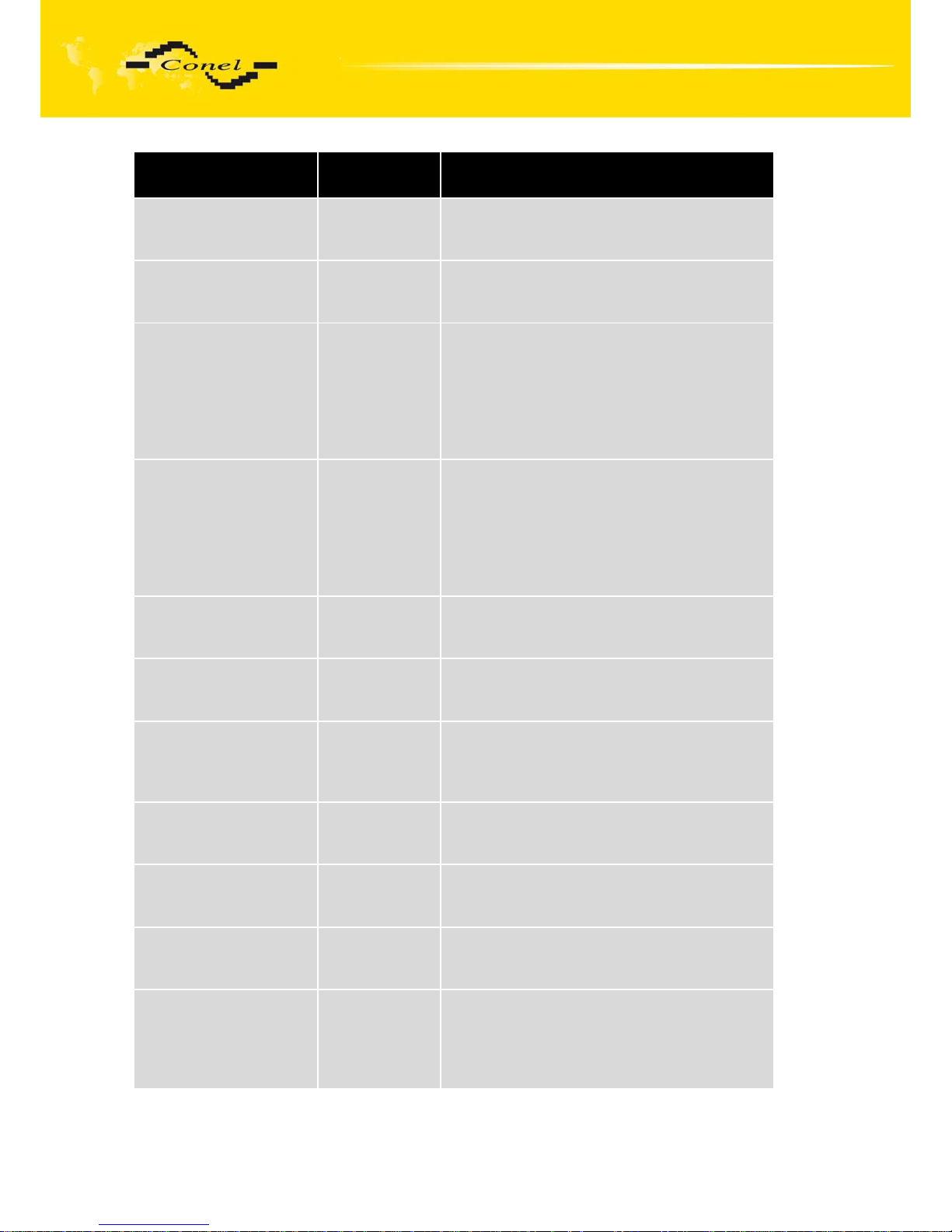
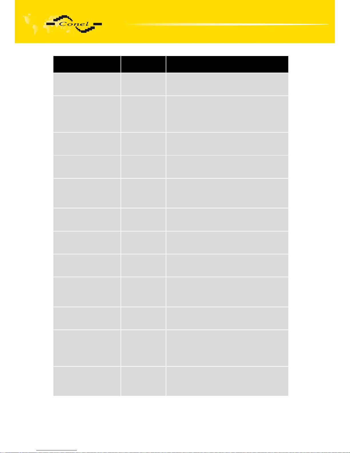
2.17. Basic parameters description
For monitoring of status, configuration and administration of the modem is RADWIN
program [1]. In right under main menu is function list where is possible choice Configuration
(Ctrl + F1). Next table describes parameters of the tap Basic. Ports description is depend on
used protocol. Protocols description is possible to get from Conel Company.
Parameter name
Set value
range
Parameter description
Serial number
--- Modem serial number information.
RF module type
--- Radio module type information.
Operating RF
frequency
403,000 up to
470,000 MHz
Defines which frequency the modems will
communicates. The same value must be set
on modems which are supposed to
communicate mutually.
Channel spacing
12,5/20/25 kHz It is frequency distance (frequency
difference) between nominal frequencies
of two neighbouring radio channels. The
same value must be set on modems which
are supposed to communicate mutually.
RF power
0,01 up to 5 W Output RF power.
AF filter
Wide band/
Narrow band
When the Channel spacing is set to 12,5 kHz
than it is possible to set this parameter to the
Narrow band. Better sensitivity is typically
achieved by these settings. For other channel
spacing this parameter is set to the Wide
band and may not be changed.
Modulation inversion
YES/NO When this parameter is set on YES than it is
possible to invert transmitting signal. For
CDA-70 modems isn't signal inverted. This
parameter may not be changed.
Firmware version
--- Parameter shows modem firmware number,
only for information.
Modulation type
2-GMSK/
Combined/
4-FSK without
FEC/4-KSK
with FEC
This parameter defines the way modulation
signal will change the characteristics of
carrier frequency. The same modulation type
must be set on modems which are supposed
to communicate mutually.
Page 32
CDA70 MODEM DESCRIPTION
32
Parameter name
Set value
range
Parameter description
RF channel protocol
--- Information about used radio channel
protocol.
Relay station
YES/NO Indicates relay property of this station. Only
for automatic tables.
Mobile station
YES/NO When this parameter is set on YES, than this
modem never works as relay station and
sends data directly to destination stations (no
relay) regardless of signal levels. Mobile
station is intended for maintenance purposes
in network.
RF channel access
type
Collision/
Coll. Free
When this parameter is set to COLLISION,
than the modem listens on RF channel and
sends data only to free channel otherwise
waits. When this parameter is set on COLL.
FREE, than the modem send data
immediately.
RF channel access
protocol
--- Information about used radio channel access
protocol.
Transmit attempts
1 up to 5 The maximal number of data (one particular
message) transmission repetition.
Packet maximum
length
128 up to 2048
bytes
Maximal possible length of transmitted data
message; the maximal adjustable message
length is 2048 bytes.
RF transmit
synchronization length
1 up to 100 Number of characters in transmitted
synchronization sequence.
Time for RF chan.
occup. recognition
4 up to 50 msec Minimal time for busy channel detection. This
time is set in mili-seconds.
Fixed time for ACK
waiting
100 up to 1200
msec
Fixed part of time out in mili-seconds for ACK
(on previously sent data) waiting.
Module time for
random ACK waiting
100 up to 1200
msec
Variable part of time out in mili-seconds for
A
CK (on previously sent data) waiting. Value
added to fixed part randomly varies from 0 to
value of this parameter.
Page 33
CDA70 MODEM DESCRIPTION
33
Parameter name
Set value
range
Parameter description
Low threshold RF
signal level
-90 up to -130
dBm
Threshold of RF signal level when the RF
channel is considered to be busy.
Maximum number of
linked packets
1 up to 10 Maximum number of packets which are
linked together and send at once. This value
must be optimized regarding channel loading
and accessibility.
Additive constant for
RSSI
--- Additive constant for RSSI size information.
Multi constant for
RSSI
--- Multiplicative constant for RSSI size
information.
Radio module check
YES/NO By setting this parameter to YES the radio
module setting is checked against modem
configuration at start-up and one hour later.
Clock synchronization
network address
0000 up to
9999 Hex
Network address which can be used for
modem time synchronization.
Clock synchronization
interface address
0 up to 255 Interface address which can be used for
modem time synchronization.
Log resets
YES/NO When this parameter is set to YES, than
reset information are stored to the journal.
Log RF channel
YES/NO When this parameter is set to YES, than
radio channel information are stored
to the journal.
Log COM ports
YES/NO When this parameter is set to YES, than
COM information are stored to the journal.
Log PPP protocol
YES/NO When this parameter is set to YES, than PPP
information are stored to the journal. For
CDA-70 modem this parameter is
unimportant.
Log DNS service
YES/NO If Agnep protocol is set on the Ethernet port
and this parameter is set to YES than DNS
information is stored to the journal.
Page 34
CDA70 MODEM DESCRIPTION
34
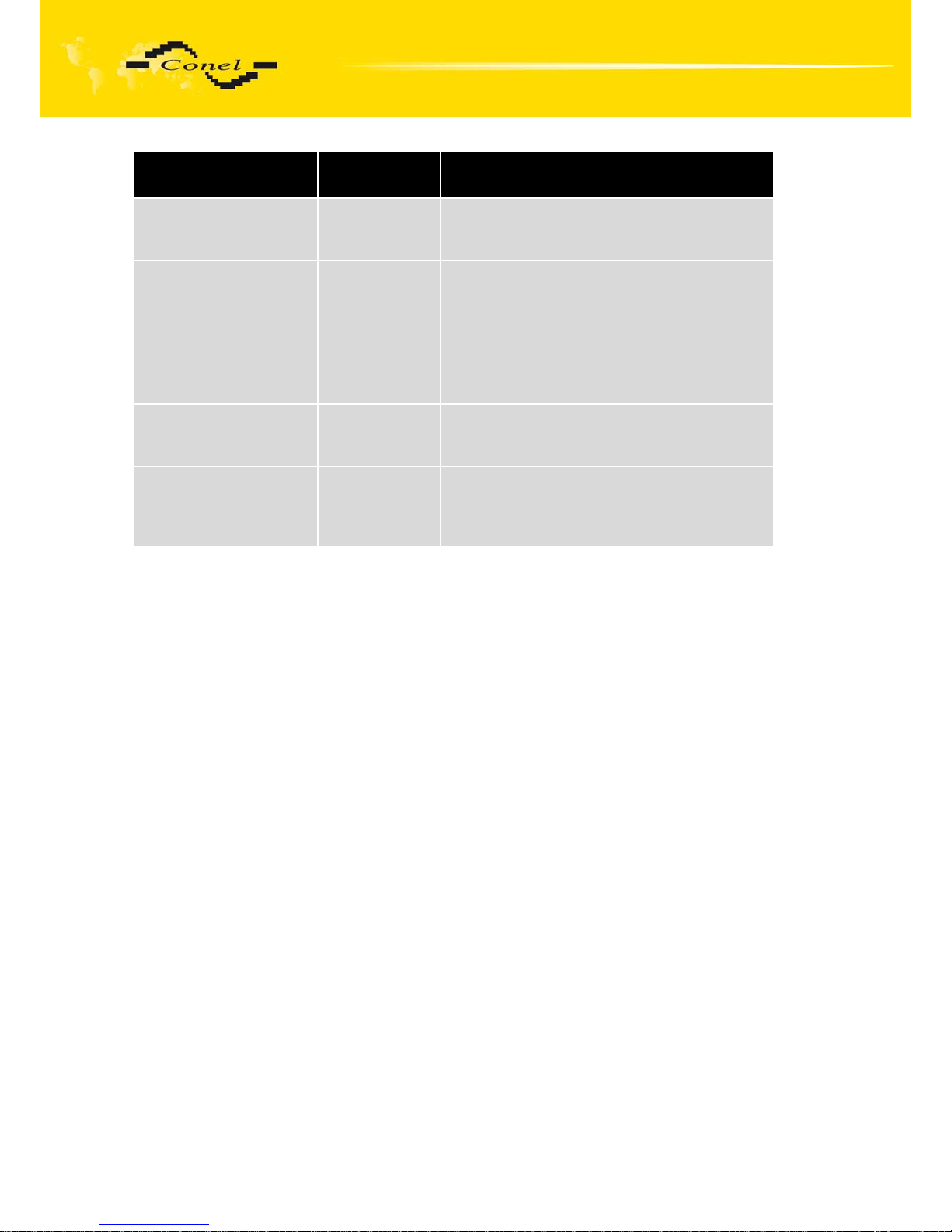
Parameter name
Set value
range
Parameter description
Log CIO
YES/NO When this parameter is set to YES, than CIO
information is stored to the journal.
Log service events
YES/NO When this parameter is set to YES, than
service events are stored to the journal.
Log ARET events
YES/NO When this parameter is set to YES, than
automated tables information are stored to
the journal.
Log ETH interface
YES/NO When this parameter is set to YES, than
Ethernet information is stored to the journal.
Port x type
RS-232/
RS-485/
M-BUS
Information about interface type on particular
port.
Page 35
CIO DESCRIPTION
35
3. CIO - analogue inputs and binary outputs
3.1. Introduction
CDA70 is equipped with a user interface (I/O) for scanning and processing of analogue
signals and for controlling (setting) of binary signals. The user can use five adjustable inputs
outputs, which are placed on the I/O connector at the back panel of the module. More about
CIO 2 modules see [3].
3.2. Description of multi-purpose signal evaluation and reception
On the input/output, there are five signals, which can be processed and controlled by
settings of the CIO module. It is possible to control these signals remotely or to send their
values in the data form to a remote location of a data network.
3.2.1.
Analogue input
Every 100 msec, the voltage value of the analogue input is read, converted to a digital
deca-bit value and adjusted by the calibration constant. The value is further average computed
according to user setting and saved in the computer memory. The basic range of the input
voltage is 0 to 5V.
3.2.2.
Binary output
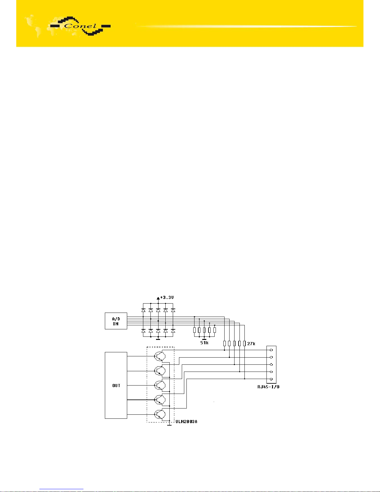
Binary output is implemented by a transistor with open collector connected to I/O
signal. When inactive (log 0), the transistor does not conduct and acts like an opened switch.
When active (log 1), the transistor acts like a switch connecting the I/O signal to the ground
(GND). In both cases, the I/O value is measured as an analogue input too. The status
of the switched circuit is being checked this way.
3.2.3.
I/O signals inside CDA70
I/O signals wiring diagram
Page 36
CIO DESCRIPTION
36
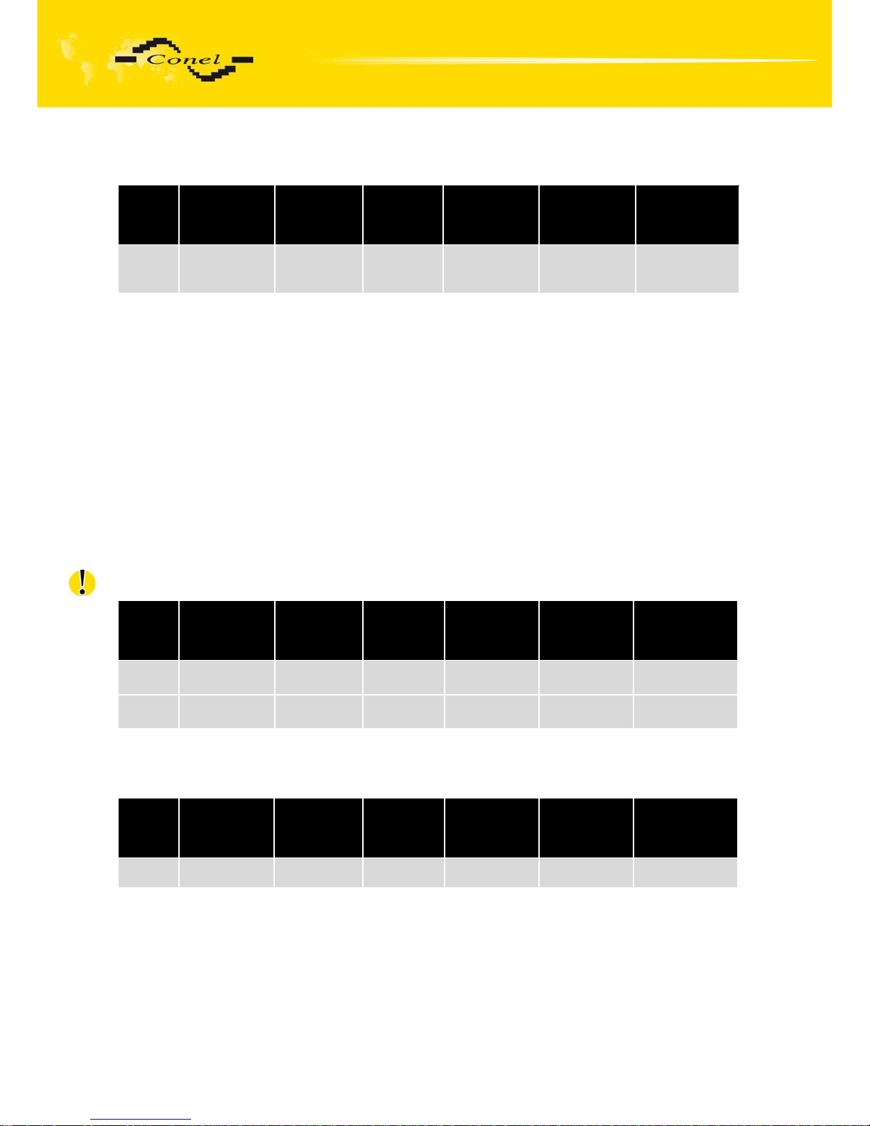
3.2.4. I/O signals parameters
Signal
name
Measuring
range [V]
Resolution
[bit]
Sampling
[msec]
Average
from
samples
Hysteresis Control level
I/O1-5 0 to 5 10 100 Optional
1 - 128
Optional
0 - 255
Optional
3.3. Measuring other CDA70 signals
3.3.1. Measuring the supply voltage
In CDA70, two more signals are evaluated. The first one is called UN+ (DC SUPLY);
it is an internal one and it measures the supply voltage at the supply terminals of CDA70.
The measuring range is 0 to 20V. The supply voltage value influences the function of CDA70.
If it drops under the set value, the VF module is disconnected because its correct function is
no longer secured and thereby, at the same time, the discharge current of a backup battery
(if used) is decreased.
The second one is INAC (AC SUPLY) linked to the supply connector (see the supply
connector description). The measuring range is 0 to 20V. The signal is protected against
overvoltage by a protective element, which blocks the voltage higher than 16V. INAC is
designed for measuring of network supply voltage presence. A change of the value is recorded
into CDA70 statistics as a dropout and start (rise) of the 230V supply voltage.
Beware - it is impossible to connect 230V supply voltage directly to the input!
Signal
name
Measuring
range [V]
Resolution
[bit]
Sampling
[msec]
Average
from
samples
Hysteresis Control level
UN+ 0 to 30 10 5000 4 2V Optional
INAC 0 to 30 10 5000 4 2V Optional
3.3.2. Measuring internal CDA70 temperature
The internal temperature is measured inside the CDA70 unit.
Signal
name
Measuring
range [°C]
Resolution
[bit]
Sampling
[msec]
Average
from
samples
Hysteresis Control level
TEP -40 to 100 10 5000 16 10 oC Optional
Page 37
CIO DESCRIPTION
37
3.3.3. Measuring DSR output signal level
On CDA70 side, DSR signals on individual user interfaces are output signals. They are
not internally controlled. Individual signals are connected via 1k8 ohms resistors to the 12V
supply voltage (the same voltage as at the supply connector of CDA70).
Due to the loading of DSR output by a 100 ohm resistor to the earth, the supply voltage
on the output drops to 2V. CDA70 recognises the connection of the service cable and initiates
the communication on this user interface using the ARNEP protocol with defined
communication parameters. It is forbidden for user applications to load the output so that
the voltage would drop below 3V. The signal can be used for user applications within
the range of 3V to 12V.
As well as the other signals, DSR values are accessible within CIO communication
reports (see the ARNEP protocol description).
3.4. Output signal for disconnection of supply voltage
The only exclusively "output" signal is PWRSV (Power Save). The signal is linked to
the supply connector (see the supply connector description). It is connected as universal I/O
signal outputs. This is an open collector that switches PWRSV signal to the ground (GND).
The output is controlled by a report, similarly to I/O outputs.
3.5. Technical parameters
Number of I/O signals on I/O port 5
Basic range of the analogue input supply voltage 0 to 5V
Maximum switched current of binary output 500 mA
Maximum switched voltage of binary output 30 V
3.6. Connecting CIO signals to user device
It is not appropriate and often even possible to connect I/O interface signals directly to
the user device. To measure current, resistance, broader ranges of voltage, it is necessary to
insert electronic circuits, which adjust the measured quantities to voltage ranging from 0 to 5V
and also protect inputs against disturbing influences and dangerous overvoltage. Moreover, it
is also necessary to insert electronic circuits for operating the power parts of the user interface
because a transistor with the open collector is able to switch current up to 500mA and voltage
up to 20V.
Two additional CIO modules, which form an interface between a user's device and I/O
signals, are created for the practical use of I/O signals
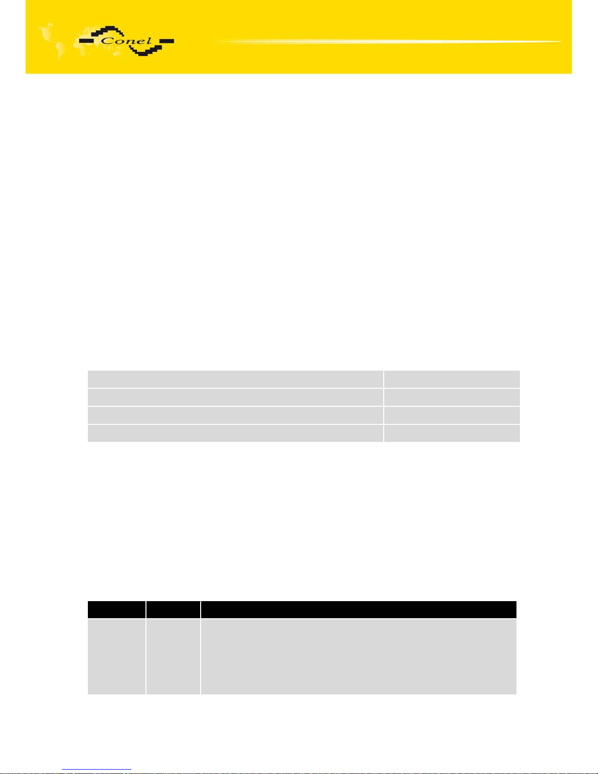
Name Type Description
CIO ANI 2 Analogue
input
Analogue differential input for small voltage, current and resistance
measuring. It includes differential amplifier with adjustable power 1 to
10000. Exact current source 0.1 to 3 mA can be used to measure
resistance. Configuration of the input signals, amplification and
current source is carried out through resistance net. Presence of the
input signal relevant to A/D converter working range is signalled by
Page 38
CIO DESCRIPTION
38
LED on the front panel. Input circuits are protected against short-time
over voltage by suppressors and against the long-time one by a
reverse fuse.
Ranges of the measured values:
U 1V, U 2V, U 5V, U 10V, U 20V
I 5mA, I 10mA, I 20mA
Pt100 100oC, Pt100 200oC, Pt100 500oC
Resistance 100 to 50000 Ohm (METRA transmitter)
CIO OPI 2 Binary
input
A single galvanic-separated digital input used for direct and alternate
signals up to 30V. It includes a bipolar opto-element that enables
processing of both input signal polarities. For AC signal, it includes
integration circuit that provides for direct processing of 50 Hz signal.
Output logical value of the measured signal is LED signalled on the
front panel. Input circuits are protected against short-time over
voltage by suppressors and against the long-time one by a reverse
fuse.
Input D.C. voltage of 3-30V
Input A.C. voltage of 3-30V rms
CIO REO 2 Binary
output
A single relay output. It includes a relay with a single changeover
contact. The changeover contact terminal is separate, common
contact is doubled (marked as C). The LED signals the presence of
the governing signal of the relay.
Maximum constant voltage 230V rms
Maximum constant current 5A rms
Page 39

REFERENCE AND LINKS
39
4. Reference
[1] Conel s.r.o.: RADWIN Program for control AGNES, 2008
[2] Conel s.r.o.: Application CGU Server, 2004
[3] Conel s.r.o.: CIO 2 User’s guide, 2008
5. Links to related products of the manufacturer
For related and referenced products and material, see the Conel website:
www.conel.cz
5.1. Systems
AGNES - a comprehensive communication system made by Conel.
5.2. Protocols
ARNEP – Advanced Radio Network Protocol – one of AGNES protocols.
5.3. Software
RADWIN - this software provides for creation, installation and administration of data
networks.
5.4. Products
CDM70 - radio data modem, the foregoer of CDA70.
CDM70L - radio data modem for shared band.
6. Product disposal informations
The WEEE (Waste Electrical and Electronic Equipment: 2002/96/EC) directive has
been introduced to ensure that electrical/electronic products are recycled using the best
available recovery techniques to minimise the impact on the environment. This product
contains high quality materials and components which can be recycled. At the end of it’s life
this product MUST NOT be mixed with other commercial waste for disposal. Check with
the terms and conditions of your supplier for disposal information.
Page 40

COMPLAINTS PROCEDURE
40
7. Complaints procedure
Dear customer,
The product you have purchased had passed manufacturer's tests and its functions
had been checked by our technician before sale. In case any defect shows up during
the guarantee period that prevents normal use we ask you to follow the Complaints procedure
when registering your claim.
To make a possible complaint procedure easier please make sure when taking over
the product that your vendor has duly filled in all the relevant parts of the warranty, including
date, seal and signature.
This Complaints procedure relates to the purchased products. This Complaints
procedure does not relate to the services provided.
Guarantee period of the products
Guarantee period of 24 months from the date of purchase is provided for the device,
source, antenna, data cable and possible accessories. The date of purchase is at the same
time date of takeover.
Registering a claim
It is necessary to register your claim at the vendor where the subject of the complaint
has been purchased. Customer shall present duly filled warranty and the complete subject
of the complaint. Subject of the complaint shall be presented in a condition adequate to that
at the moment of purchase.
Caution!
The vendor is not responsible for keeping individual settings or data saved
in the subject of the complaint.
The customer is obliged to clarify the defect or how it is displayed and what claim he
intends to register.
Processing the complaint
The vendor shall provide free remedy depending on particular conditions, or replace
the subject of the complaint for a new product, or settle the matter in another manner
in compliance with the Civil Code and the Act on consumer's protection.
As of the moment the claim is registered by the customer and the subject
of the complaint is taken over by the vendor the guarantee period stops running.
The guarantee period continues on the date of takeover of the repaired subject
of the complaint or replaced faultless product by the customer, or should it not be taken over
on the date the customer is obliged to take over the repaired or replaced product. In case
the vendor replaces the subject of the complaint for a new product, the original subject
of the complaint becomes property of the vendor and the new product becomes property
of the purchaser. New guarantee period starts from takeover of the new product. In cases
when the vendor settles the matter upon agreement with the customer by replacement
of the subject of the complaint for a faultless product, the new guarantee expires
1. After 12 months since the replaced product was taken over by the customer.
2. On the date when the original guarantee period (subject of the complaint) would
have expired should it not have been replaced, whichever comes first.
Page 41

COMPLAINTS PROCEDURE
41
3. The claim is deemed unsubstantiated when the defect is not found by the vendor
processing the complaint or the defect is not covered by the guarantee under Article
3 of the procedure.
4. In case the claimed defect is not found and functionality is proven to the customer,
the customer is obliged to pay demonstrable cost related to expert assessment
of the claimed defect.
5. In case defect is found when processing the complaint that is not covered
by the guarantee (extra-warranty repair), the vendor shall inform the customer
and the customer shall inform the vendor whether he/she wishes to have the defect
repaired for the price set. A protocol shall be made on exact conditions of the extrawarranty repair and signed by both the customer and the vendor. Should
the customer not require remedy through extra-warranty repair under the conditions,
the device shall be returned to him/her after he/she pays the demonstrable cost
of expert assessment.
The guarantee does not cover defects due to
1. Mechanical damage (fall and the like).
2. Use of inadequate or not recommended sources and other accessories.
3. Connection of the product with non-standard accessories.
4. Installation or use of the product conflicting with the Manual or use for other
purposes than usual for this type.
5. Improper manipulation, or an intervention of unauthorised person or other service
than authorised by the manufacturer.
6. Effects of natural forces (flood, fire etc.) or other local phenomena) storm, mains
over voltage and the like).
7. Storage under unauthorised temperatures.
8. Operation in a chemically aggressive environment.
Other conditions
The fact the subject of the complaint does not conform to parameters set for other
similar product types shall not be considered a fault. To assess whether it is a case of covered
fault the parameters stated in the technical documentation for the product are decisive.
The guarantee expires in any case of changes to the subject of the complaint
or damaged or otherwise unreadable serial number.
Page 42
WARRANTY
42
8. Warranty
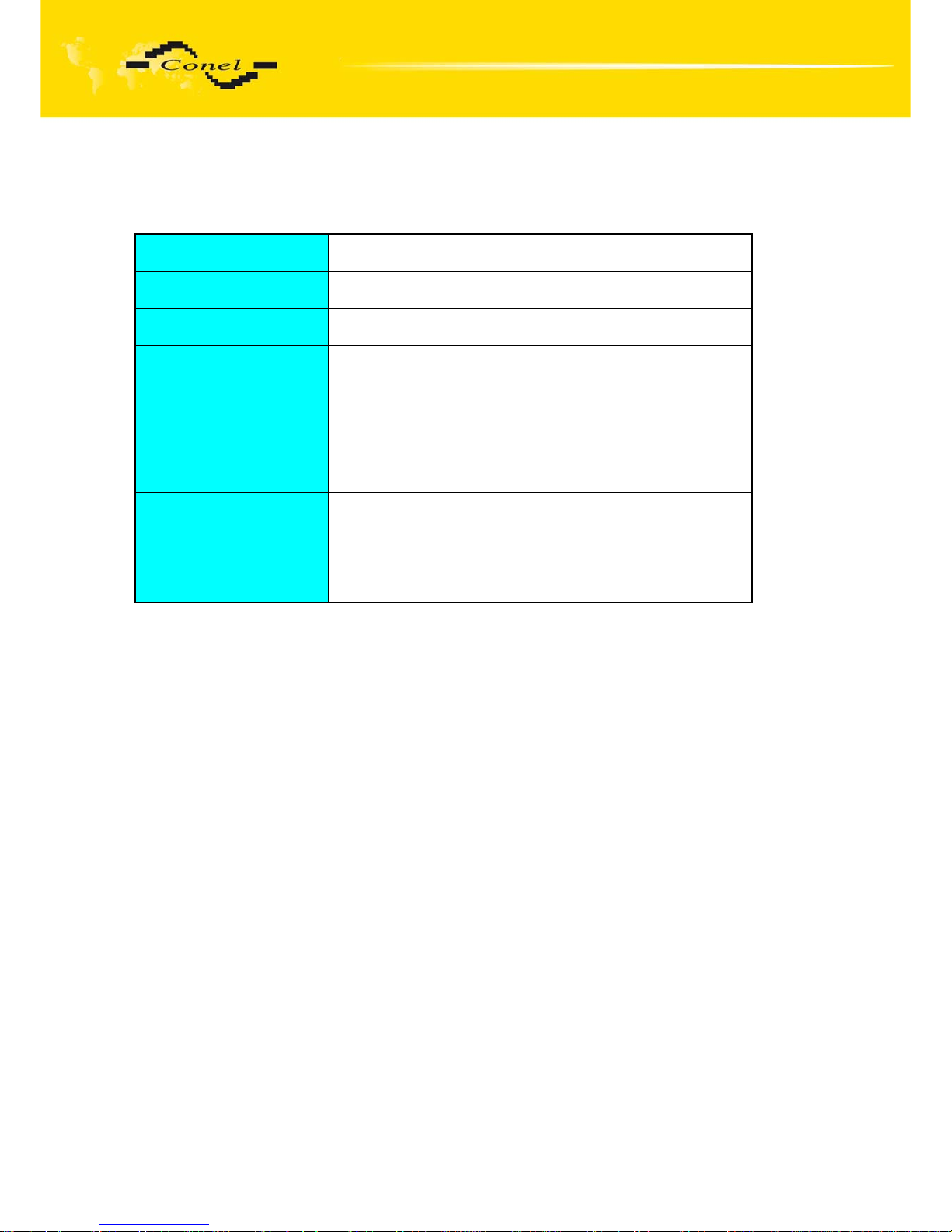
Device type
Serial number
Guarantee period (months)
Vendor
Date of purchase
Seal of the vendor
Page 43
WARRANTY
43
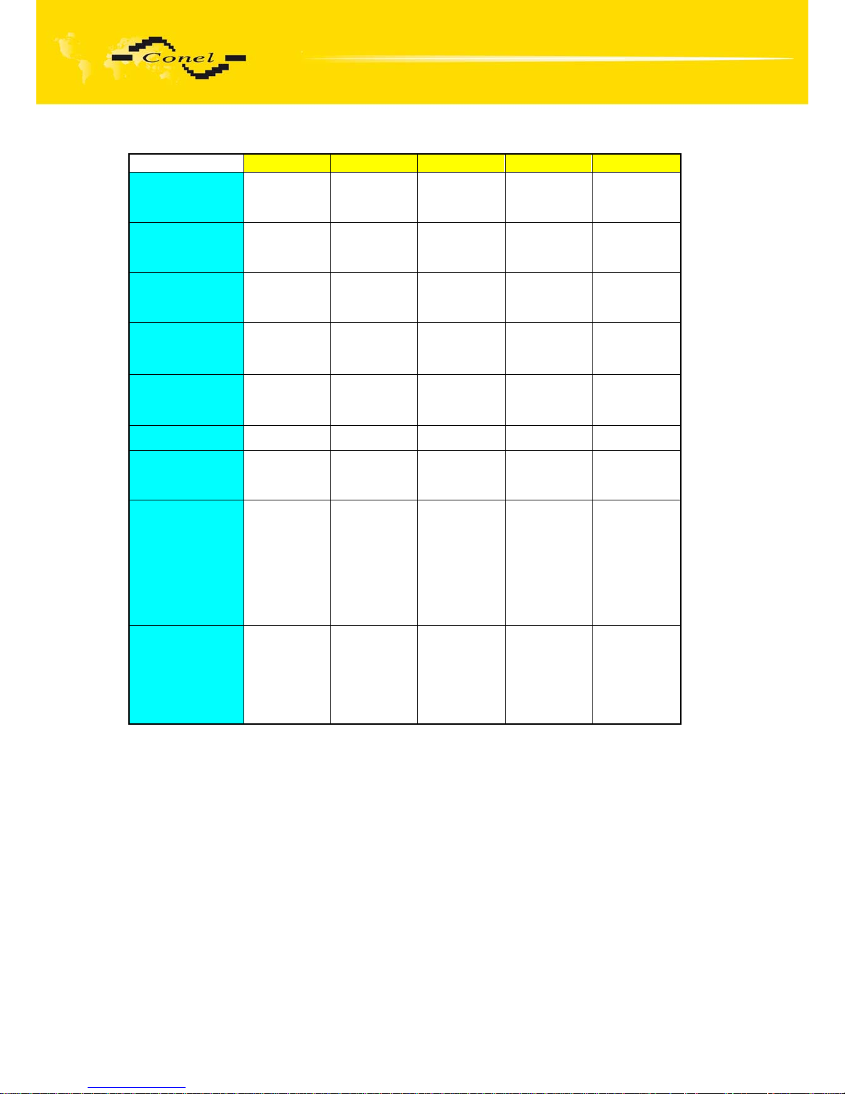
1 2 3 4 5
Date of complaint
registration
Complaint
protocol number
Date of reception
of the device in
repair shop
Date of finished
repair
Number of repair
sheet
Warranty repair YES - NO YES - NO YES - NO YES - NO YES - NO
New serial
number of the
device
Notes
Seal of the repair
shop
 Loading...