

Page 1
CONDUX USER’S GUIDE & SAFETY MANUAL
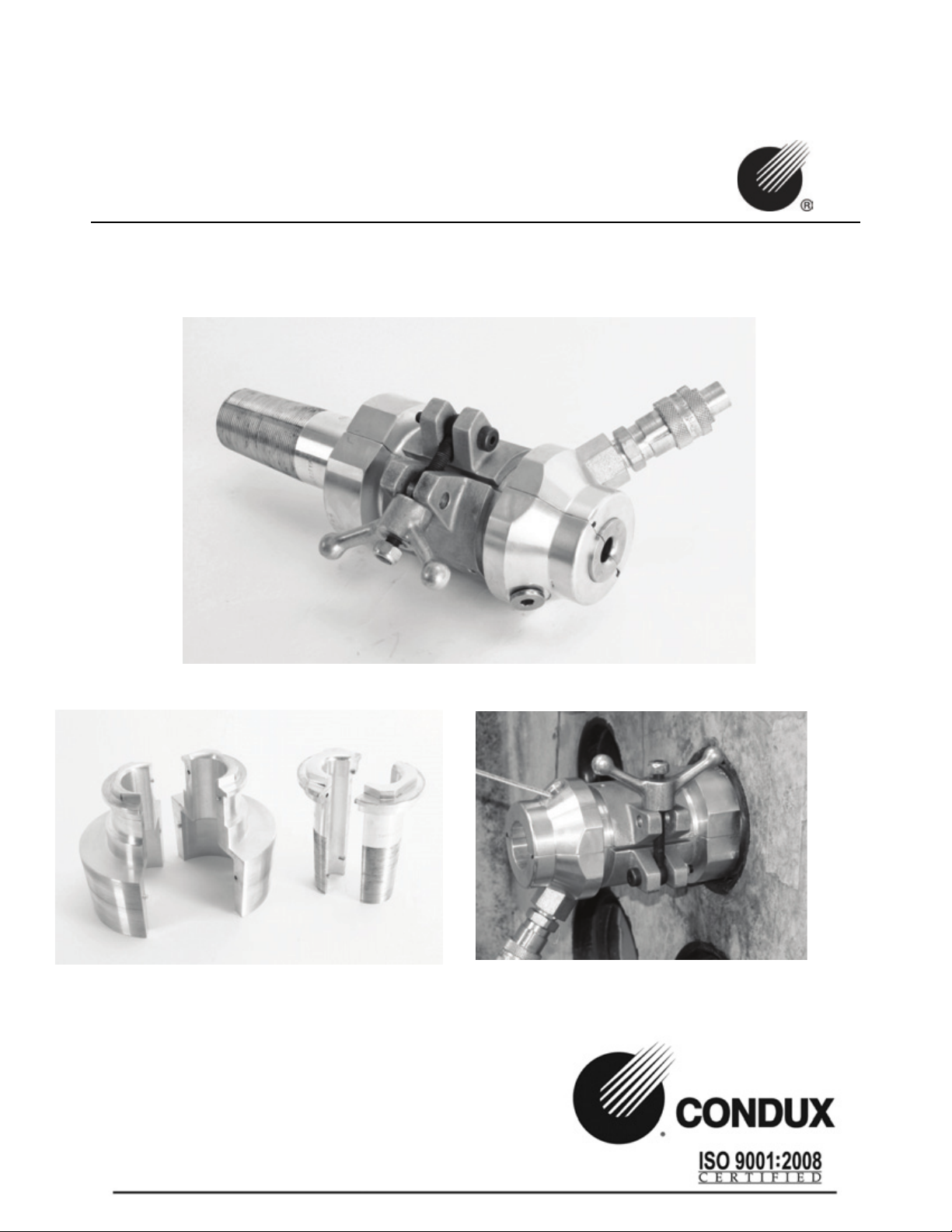
WINCH LINE BLOWER SYSTEM
Page 2

IMPORTANT SAFETY NOTICE
Read and understand all procedures and safety instructions before using a Condux Winch Line Blower.
Observe all safety information on this page and note specific safety requirements as explained by procedures in
this manual. Failure to follow these instructions could result in serious personal injury or death.
ADVERTENCIA:
Favor de leer y comprender todas las instucciones de operación y seguridad antes de usar la máquina. Si Ud. no
comprende las instrucciones favor de consultarle a su jefe.
Save this user’s guide for future reference.
For any information related to the machine (use, maintenance, spare parts) always state Model, Serial Number,
Manufacturing Year and Order. This data can be found in the machine identification table.
Manufacturer:
Condux International Inc.
145 Kingswood Drive
Mankato, MN 56002-0247
1-507-387-6576
Fax 1-507-387-1442
Internet: http://www.condux.com
E-mail: cndxinfo@condux.com
Page 3

Table of Contents_________________________
1. GENERAL INFORMATION
Purpose of the Winchline Blower……………………….2
Technical Information…………………………………..2
Safe Operating Practices………………………………...3
Winch Line Blower Selection………..…………………..4
2. OPERATOR’S INSTRUCTION
Winch Line Blower Installation…………………………5
Winch Line Blowing Procedure…………………………11
Winch Line Blower Removal...………………………….12
3. WINCH LINE BLOWER ADAPTER
Purpose of the Winch Line Blower Adapter…………….15
Winch Line Blower Adapter Installation………………...15
Winch Line Blower Adapter Removal…………………...19
4. TROUBLESHOOTING
Solutions to possible problems………………………….21
5. APPENDIX
Winchline Blower Seal-Off Body Assembly……………..23
Condux Control Valve Assembly P/N 08209300……….25
Condux Air Hose Assembly P/N 08209310…………….26
Condux Conduit Missile Wear/Replacement Parts……...27
Winchline Blower Adapter Assembly…………………....28
Warranty Information…………………………………...29
Page 4
1. General Information
Purpose of the Winch Line Blower
The Condux Winch Line Blower is a unique device for inserting winch lines directly into
underground conduit before cable pulling or conduit proving operations. The winch line blower is
comprised of three main parts that, when used in conjunction with an air compressor and a cable
pulling winch mechanism (truck, trailer, or portable), will propel a standard steel winch cable into
an unobstructed, unoccupied, airtight, plastic conduit run at an average speed of 100 feet per
minute.
The Condux winch line blower will work with nearly all type of existing steel cable winches that
are currently being used for the installation of underground
utility cables.
Because of the unique design of the winch line blower, it will
operate in a wide range of conduit sizes, from 2to 6 inch duct,
and with various diameter winch lines up 7/8” (14mm)
without compromising efficiency.
The three main parts of the winch line blower are the
winchline blower body assembly, the missile and the control valve assembly. When each part of
the system is properly installed and maintained, this provides a means of using existing winch line
equipment to speed up cable installation procedures by as much as 1000 percent.
Technical Information
1. CONDITION OF USE
Temperature from 21° F (-6 C) to 110 F (+43 C)
Humidity from 30% to 90% +/- 5%
Weather conditions relevant to working conditions
Natural and/or artificial lighting of the worksite, minimum 200 lux
2. AIR COMPRESSOR REQUIREMENTS
Pneumatic Pressure: 175 psi (12 bar) Maximum
Required Flow Capacity: 375 SCFM (11 m3/min) Maximum
Control valve air hose fittings need to be compatible with Dixon “Air King”
universal couplings.
Safety Pop-off Valve on Control Assembly set for 90 psi.
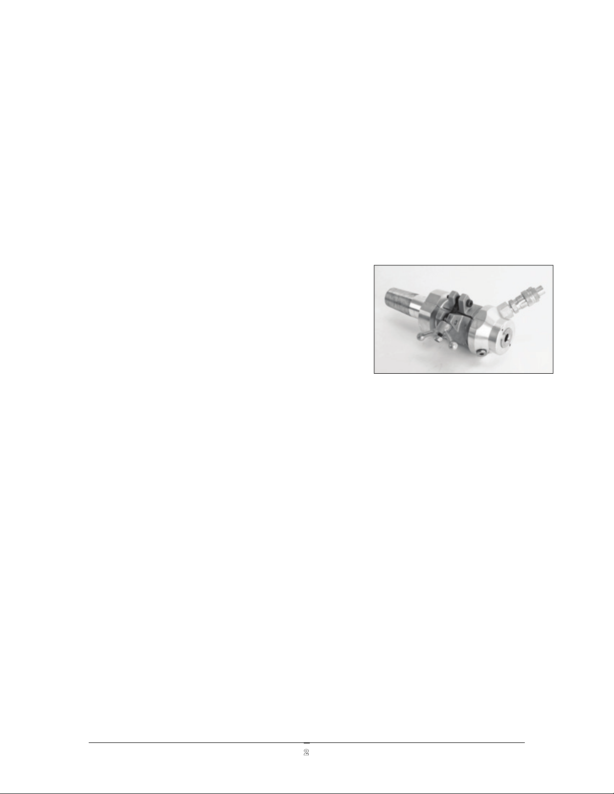
CONDUX WINCH LINE BLOWER
2
Page 5
CONDUX WINCH LINE BLOWER
3
Safe Operating Practices
All tools, materials and equipment manufactured and supplied by Condux International are
designed to only be used by trained craft personnel. The information in this manual is essential for
the safe use of the Condux Winch Line Blower.
Operating procedures and guidelines must be read and understood by all personnel prior to using
any tools, materials, or equipment from Condux International.
OPERATOR QUALIFICATIONS
a) Operator in charge of the Winch Line Blower and installation project must be
appropriately dressed.
b) Operator must also wear the necessary protective equipment such as gloves, boots,
helmet, etc.
c) Operator must carefully follow all advisements contained in the instruction manual.
d) Operator must have work area kept clean of obstacles that might inhibit a safe working
area.
Condux will not be held liable for any injury or damage to either persons or property resulting
from the misuse of Condux equipment.
!WARNING: The Condux Winch Line Blower must be properly installed as
instructed. Failure to properly install the Winch Line Blower could result in severe
personal injury or damage to existing cables or conduit in the utility service
access vault.
!CAUTION: The Winch Line Blower is designed for use only in PVC and
polyethylene conduit. It will not operate properly and may cause personal injury
or physical damage if used in fiberglass, steel, concrete or other types of non-
plastic conduits.
This users guide and safety manual is intended to familiarize operators with the use and safety
procedures of the Condux Winch Line Blower.
This manual should be kept available to all operating personnel.
Page 6
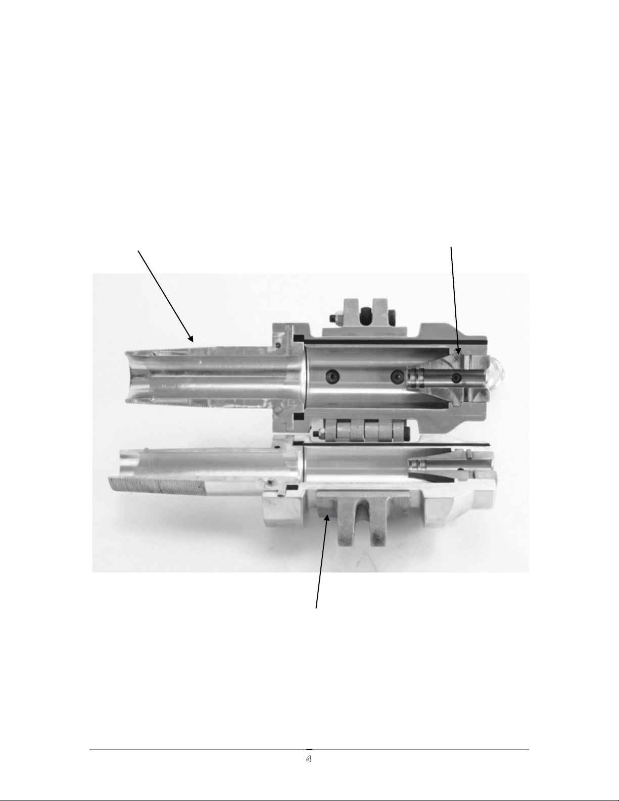
Winch Line Blower Seal-Off Selection
Threaded Adapter
Rope Venturi
Winchline Blower Body
1. Determine type(s) and diameter(s) of conduit in which the winch line will be inserted.
2. Select the correct threaded adpater to cover the range of conduit types and sizes
being used.
3. Select the proper size rope venture. Comes standard with ½” – 9/16” venture.
4. Select the proper missile size for the conduit sizes that are going to be used.
CONDUX WINCH LINE BLOWER
4
Page 7
CONDUX WINCH LINE BLOWER
5
2. Operator’s Instructions
Winch Line Blower Installation Procedure
!WARNING: Do not use around live circuits. The Winch Line Blower is constructed
of steel and aluminum, as such is highly conductive. Electric shock may occur is
contact is made with live circuits. Always be certain that power has been
disconnected.
!CAUTION: Standard utility service access vault opening procedures must be
followed which include work area protection and gas detection. Hard hats, eye
and ear and foot protection, must be worn whenever working in utility service
access vaults.
1. Clean out the end of the conduit to remove any dirt or gravel that may get between
the conduit and the threaded adapter.
2. Place about ½ quart of cable pulling lubricant (such as Poly J) into the conduit.
While this is not required, it does help in installing the missile and helps to increase
the efficiency of the winch line blower.
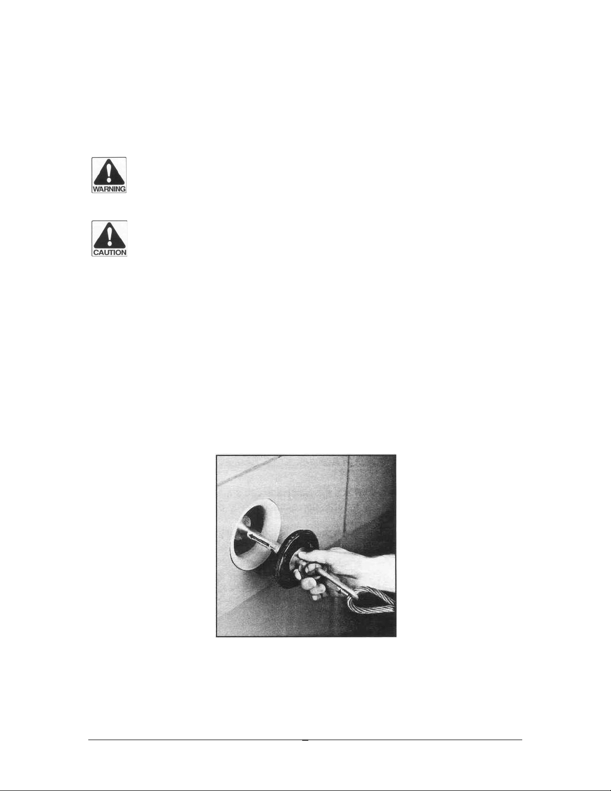
3. Attach the missile to the end of the winch line using the connector supplied with the
winch line blower. (See Fig. 1) The large metal disc must be forward in the direction
of winch line travel (as shown by the label on the missile).
Figure 1: ATTACH THE MISSILE
Page 8

CONDUX WINCH LINE BLOWER
6
!CAUTION: Always know approximate length of the conduit runs and make
certain the winch drum contains enough winch line cable to reach the entire
distance before using the winch line blower.
!CAUTION: Inspect the winch line cable or know the condition of the cable before
using the winch line blower. Replace any cables that are kinked or have worn or
broken strands before using the winch line blower.
4. Insert the missile into the conduit and push into the conduit approximately one arms
length. (See Fig. 2)
FIGURE 2: INSERT MISSILE INTO CONDUIT
5. Place split-threaded adapter around winch line and screw threaded adapter into pipe
until tight by hand. Use adjustable wrench and screw threaded adapter one more full
turn. See Figure 3 & 4
!CAUTION: Before each use, visually inspect the Winchline Blower Body,
threaded adapters, and the missiles for signs of wear, fatigue, and/or breakage. If
any of these items show signs of wear, they should be replaced or system
function and efficiency will be affected (Reference Appendix).
Page 9
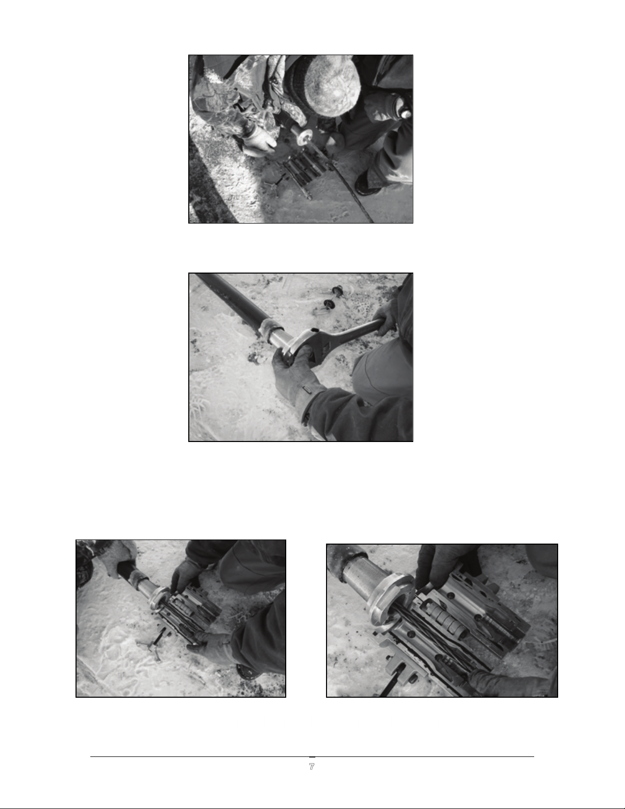
Figure 5 7 6 Install Winchline Blower Body onto the Threaded Adapter
Figure 3 Place Threaded Adapter into Duct
Figure 4 Tighten Threaded Adapter Using a Wrench
6. Install winchline blower body onto the threaded adapter by matching the threaded
adapter’s lip to the winchline blower body’s groove. See Figure 5 & 6
CONDUX WINCH LINE BLOWER
7
Page 10
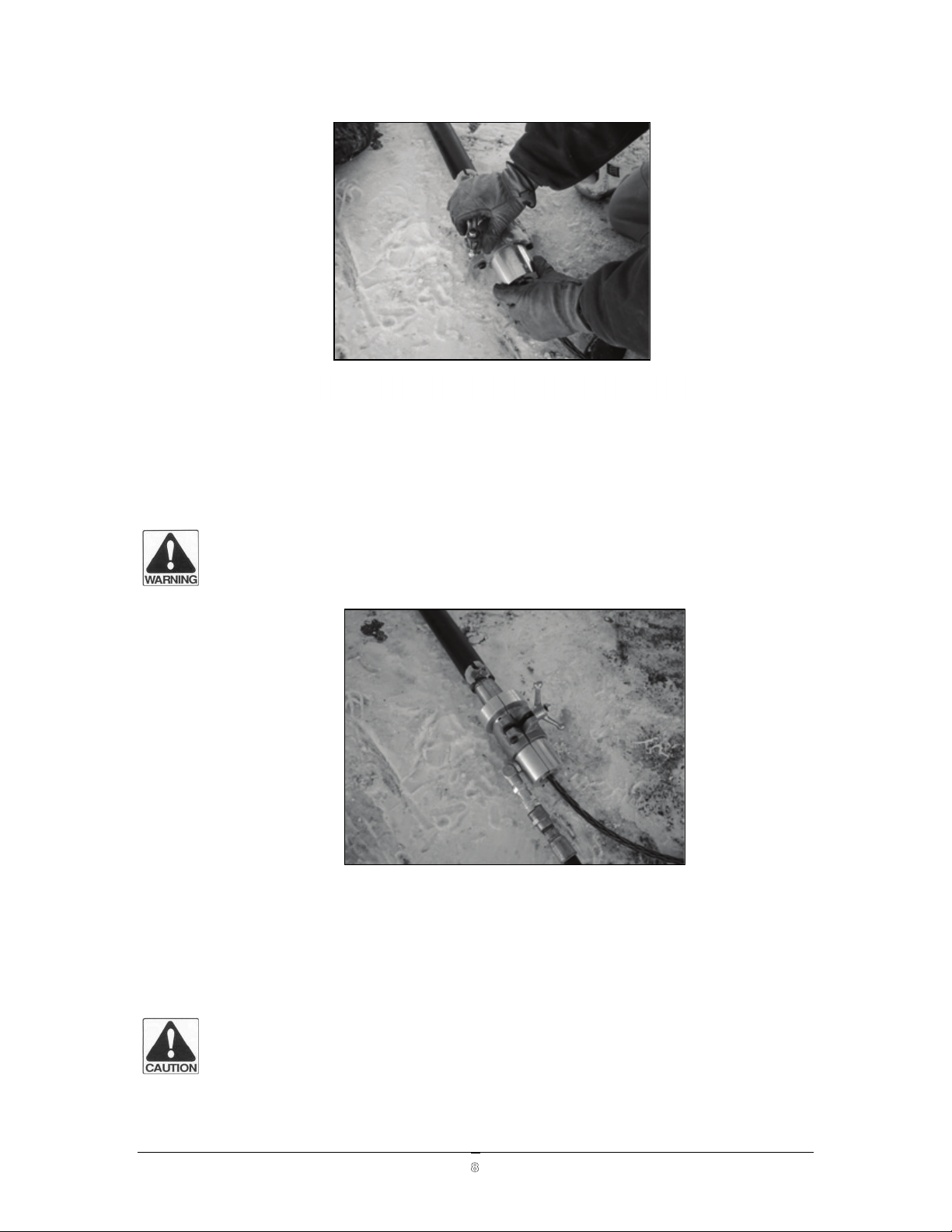
7. Close winchline blower body and secure by tighten the speedball handle securely. do
Figure 7 Close and Secure Winchline Blower Body
not over tighten. See Figure 7
!WARNING: The Threaded Adapters should be screwed tight into the duct to
ensure that the Winchline blower does not blow out of the conduit and severely
injure persons or damage property.
Figure 8: Align The Winch Line
8. Ensure that winchline is entering in a straight line. Check the winch line alignment to
ensure that the winch line is not hung up or restricted and that it will feed through the
winchline blower smoothly. See Figure 8
!CAUTION: Always guide the winch line into the winchline blower parallel with
the center line of the conduit. Use additional sheaves or cable guides if
necessary.
CONDUX WINCH LINE BLOWER
8
Page 11
CONDUX WINCH LINE BLOWER
9
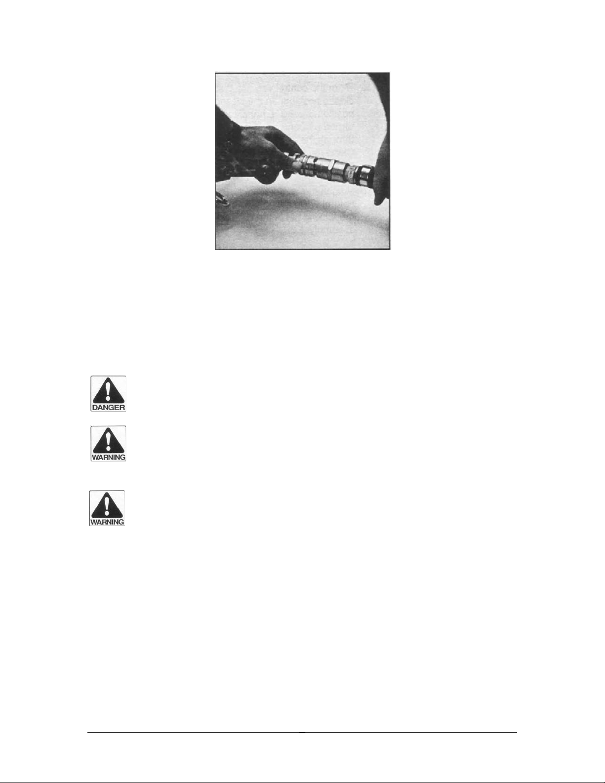
Figure 9: Attach Air Hose
9. Attach the air hose to the seal-off body assembly and tighten the locking ring on the
air connector. Rotate the 45° angle fitting away from the winch line channel and the
winch line to prevent tangling and wear of the air hose or connectors. See Figure 9
10. Run the air hose out of the utility service access vault, attach to the Control Valve
assembly, and tighten the locking ring on the air connector.
!DANGER: NEVER REMAIN IN EITHER START OR EXIT OF UTILITY SERVICE
ACCESS VAULTS DURING THE BLOWING PROCEDURE. SEVERE PERSONAL
INJURY OR DEATH COULD RESULT.
!WARNING: Do not attempt to operate the winch line blower with a different
control valve than what is supplied with the winch line blower kit. The seal-off
could blow out of the conduit or the conduit itself could rupture.
!WARNING: Check that all air hose connections are securely attached, and that
the locking ring is in place and tight.
11. Turn the control valve to the closed position (see Figure 10). In the closed position,
the valve handle will be turned perpendicular to the air flow through the fitting. Close
the outlet valve on the air compressor.
Page 12

CONDUX WINCH LINE BLOWER
10
Figure 10: Close Control Valve
12. Attach the compressor hose to the control valve assembly and insert the locking pin
the connector assembly.
13. Start the air compressor. The recommended air compressor size should be 75 to 185
CFM and 50 to 110 psi.
You are now ready to blow the winch line into the conduit.
Winch Line Blowing Procedure
!DANGER: ALL PERSONNEL MUST BE OUT OF THE START AND EXIT UTILITY
SERVICE ACCESS VAULTS DURING THE BLOWING PROCEDURE. SEVERE
PERSONAL INJURY OR DEATH COULD RESULT FROM FAILURE TO OBEY THESE
RULES.
1. Verify that all personnel are out of the start and exit utility service access vaults or
utility service access vaults.
2. Verify that the control valve is in the closed position.
!CAUTION: Keep the work area clean and free of debris. The work area should
provide good footing.
Page 13

CONDUX WINCH LINE BLOWER
11
Note: One person should be in charge of the control valve assembly and, if positioned properly,
should be able to view the winch line feeding off the winch drum, view the cable feeding down
into the utility service access vault around the sheave, blocks, etc., and monitor the condition of
the winch while it is being propelled. A second person should assist in monitoring the winch line
and keep in contract with the exit utility service access vault. Two-way radios are recommended
so the personnel at each end of the conduit run can be aware of the situation status immediately.
Figure 11: SLOWLY OPEN CONTROL VALVE
3. Open the outlet valve on the air compressor See Figure 11.
4. Slowly open the winch line blower control valve assembly. The control valve
assembly can be slowly opened by turning the valve handle in line with the air flow.
The missile will begin to move forward towards the exit utility service access vault,
pulling the winch line with it. Allow all slack to come out of the winch line before
opening the valve fully. Continue opening the control valve while constantly
monitoring the status of the winch line.
Page 14

CONDUX WINCH LINE BLOWER
12
Figure 12: MONITOR STATUS
5. Continue monitoring the winch line status and the pressure gauge on the control
valve assembly, Figure 12. Average pressure reading during normal missile blowing
operations should be approximately 70 – 90 psi.
!DANGER: DO NOT ATTEMPT TO GRAB ONTO THE WINCH LINE TO ASSIST ITS
TRAVEL OR SLOW IT DOWN. SERIOUS PERSONAL INJURY OR DEATH MAY
RESULT FROM FAILURE TO OBEY THESE RULES.
!DANGER: DO NOT LEAVE THE MOVING WINCH LINE UNATTENDED. PERSONNEL
OR EQUIPMENT COULD BECOME ENTANGLED, RESULTING IN SERIOUS
PERSONAL INJURY OR DEATH.
!CAUTION: Do not tamper with or remove the pressure relief valve. Pressure must
be limited to 90 psi. If the pressure exceeds 90 psi., immediately shut the control
valve and check the pressure gauge and the pressure relief valve for proper
operation. If no faults can be found, return the control valve assembly to Condux
International Inc. for repair or replacement (see Appendix for return instructions).
NOTE: Starting and stopping of the winch line blower repeatedly during one conduit run may
put undue stress on missile and winch line connections and/or winch line drum. Once the missile
and winch line are moving forward, keep air pressure and flow constant to propel the winch line
at an average rate of 100 feet per minute.
6. While monitoring the winch line blowing procedure, use care to prevent the winch
line and missile from “out running” the air compressor. This is characterized by the
winch line jumping, flapping or surging (shooting into the conduit very quickly, then
stopping, and shooting quickly into the conduit again). If this begins to occur, slow
down the air flow by partially closing the control valve until the winch line feeds off
the drum SMOOTHLY and CONSISTENTLY.
Page 15

CONDUX WINCH LINE BLOWER
13
!WARNING: Winch line cable must be kept tight and must not be allowed to jump,
flap, surge, or become slack. Damage to utility service access vault equipment
may result.
7. If the winch line is proceeding smoothly and consistently, listen for the exit end
personnel to relay that missile and winch line have arrived. If the winch line does not
proceed smoothly or stops before reaching the exit, follow the troubleshooting
guide in the following section.
!DANGER: READ AND UNDERSTAND THE TROUBLESHOOTING INSTRUCTIONS
BEFORE USING THE WINCH LINE BLOWER SYSTEM. FAILURE TO FOLLOW THESE
INSTRUCTIONS COULD RESULT IN SERIOUS PERSONAL INJURY OR DEATH.
Winch Line Blower Seal-off Body Removal
Figure 13: MISSILE ARRIVES
1. Once the missile arrives in the exit utility service access vault, close the control valve
on the control valve assembly. See Figure 13
2. Close the outlet valve on the air compressor and shut off the compressor.
3. Remove the air hose from the control valve assembly to assure all air pressure is
removed from the system and cannot be accidentally applied while in the access vault.
!CAUTION: ALLOW THE EXCESS AIR TO BLEED OFF FROM THE CONTROL VALVE
ASSEMBLY AND THE SEAL-OFF BODY ASSEMBLY PRIOR TO ENTERING THE
UTILITY SERVICE ACCESS VAULT.
4. Disconnect the air hose from the seal-off body assembly and pull the air hose out of
the utility service access vault and out of the way.
Page 16

CONDUX WINCH LINE BLOWER
14
5. Remove the winchline blower assembly from the conduit by turning the winchline
blower body counter-clockwise until the unit can be removed from the duct.
6. Set the winchline blower off to one side and out of the way.
7. The missile and connector must be removed from the winch line at the exit utility
service access vault. The winch line can then be prepared to pull in the cable
assemblies or a mandrel, depending on job requirements.
!WARNING: Never attempt to pull back mandrels or cable with the winchline
blower assembly still installed in the conduit. Damage to the seal-off body
assembly or the conduit will result.
!CAUTION: Keep all components of the Winch Line Blower Kit clean and free of
all foreign materials.
Page 17

3. Installing Measuring Tape
Installation Procedures
1. Clean out the end of the conduit to remove any dirt or gravel that may get between the
conduit and the Threaded Adapter. Apply a ¼” cup of lubricant into the duct system.
2. Remove rope venture if installed See Figure 1
Figure 1 Remove Rope Venturi
3. Insert the seal disk plug into rope venturi slot See Figure 2
Figure 2 Insert Seal Disk Plug
CONDUX WINCH LINE BLOWER
15
Page 18

4. Remove Hex plug using a 5/16” hex wrench and install 3/8” rope adapter see Figure 3
and Figure 4.
Figure 3 Remove Hex Plug
Figure 4 Insert 3/8” Rope Adapter
!CAUTION: Always know approximate length of the conduit runs and make
certain the measuring tape reel contains enough measuring tape to reach the
entire distance before using the winch line blower blower.
CONDUX WINCH LINE BLOWER
16
Page 19

5. Insert measuring tape through the 3/8” rope adapter See Figure 5
Figure 5 Insert Measuring Tape through 3/8” Rope Adapter
6. Attach measuring tape to carrier and install carrier into the duct See Figure 6
Figure 6 Attach Measuring Tape to Carrier and Insert into Duct
!CAUTION: Before each use, visually inspect the winchline blower body assembly,
threaded adapters and missiles for signs of wear, fatigue, and/or breakage. If any of
these items show signs of wear, they should be replaced, or system function and
efficiency will affected (Reference Appendix)
CONDUX WINCH LINE BLOWER
17
Page 20

7. Screw threaded adapter into pipe until tight by hand. Use adjustable wrench and screw
threaded adapter one more full turn See Figure 7 & 8
Fig. 7 Insert Threaded Adapter into Duct
Fig. 8 Insert Threaded Adapter into Duct
8. Install winchline blower body onto the threaded adapter. Close winchline blower body
and secure by tighting the speedball handle securely, do not over tighten See Figure 9 and
Figure 10.
CONDUX WINCH LINE BLOWER
18
Page 21

Figure 9 Install Winchline Blower Body
Figure 10 Secure Speed Ball Handle
CONDUX WINCH LINE BLOWER
19
Page 22

9. You are now ready to install your measuring tape
10. For Winch Line installation procedures refer back to Section 2 of this manual.
CONDUX WINCH LINE BLOWER
20
Page 23

CONDUX WINCH LINE BLOWER
21
4. Troubleshooting
Solutions to possible problems
!WARNING: DO NOT ENTER THE UTILITY SERVICE ACCESS VAULT TO CHECK
THE MISSILE OR SEAL-OFF WHILE THE SYSTEM IS UNDER PRESSURE. SHUT OFF
THE AIR SUPPLY AND DUMP THE RELIEF VALVE PRIOR TO ENTERING THE
UTILITY SERVICE ACCESS VAULT.
PROBLEM
SOLUTION
THREADED ADAPTER DOES NOT FIT
INOT THE CONDUIT.
1. Wrong size threaded adapter was
selected
MISSILE GOES INTO CONDUIT A
DISTANCE BUT WILL NOT EXIT AT
OTHER END.
1. If air is escaping at the exit end, the
air is bypassing the missile. The
missile is either worn out or is the
wrong size for the conduit in
which it is being used. The missile
will have to be pulled back out of
the conduit and replaced. Follow
the removal process for the seal-off
body assembly as listed in the
previous section and use the winch
truck to pull back the missile.
2. If no losses are found at either end
of the conduit run, the missile may
have stopped due to a conduit
obstruction or due to an unsealed
conduit run. In the latter case, the
Condux Winch Line Blower will
not properly function. In this
instance, the seal-off body
assembly must be removed from
the conduit as described in the
previous section, the missile must
be pulled back out of the conduit
by the winch line, and another
method of inserting the winch line
into the conduit must be used.
MISSILE GOES INTO CONDUIT A
DISTANCE BUT WILL NOT EXIT AT
OTHER END DUE TO A CONDUIT
1. The Condux Winch Line Blower
will push water, sand, and small
gravel in front of the missile and
Page 24

CONDUX WINCH LINE BLOWER
22
OBSTRUCTION.
will clear the conduit of light
obstructions. The missile is also
able to maneuver through most
areas where the conduit may be
deformed and flattened. If the
missile is not able to pass through
the conduit, the conduit is fully
plugged or has a major conduit
obstruction.
MISSILE GOES INTO CONDUIT A
DISTANCE BUT WILL NOT EXIT AT
OTHER END DUE TO TOO MUCH
BACK FORCE ON THE MISSILE.
1. The winch line is exerting too great
of a back force on the missile to
propel the missile and cable any
further. This may be due to too
many bends in the run, the distance
of the conduit run being too great,
or the tension on the winch line
being too large.
SEAL OFF ASSEMBLY SLIPS OUT OF
THE PIPE
1. Using an adjustable wrench screw
the threaded adapter into the duct
tighter.
2. Check the threads for wear.
Page 25

CONDUX WINCH LINE BLOWER
23
5. Appendix
Winch Line Blower Body Assembly
Page 26

CONDUX WINCH LINE BLOWER
24
Winchline(Blower(Body(Assembly!
ITEM
PART(
NUMBER
DESCRIPTION
QTY
"
#$%$#"&'
()*++!,-!./0123456!!748
"
&
#&&$$###
90:;!:<,7456!,</=:;3!2!">&5=829
" ( #&&$$*?'
,0=-,3;@A,2-457!!9#B2#)%!C!"'99!"$2$--!
& B #&&$$''*
5/8A5D:<,!!9#'2")##!,E
" * #&&$$'?B
5/8A5D:<,!!9#$2")&*!,E
" ' #&&$$%$%
F;G!134H;3!2!&)*99
" % #&&$?&?(
-@456!I<:8!!9"#2")*#!C!"&*99
" $ #&&$?&?B
-F</:1;3!-,3;@!!9"#!C!B#99!J9#$2")&*!8F3;01-K
" ? #&&$?&?*
-F</:1;3!-,3;@!!9#$!C!%#99!J9#'2")##!8F3;01-K
"
"#
#&&$?&?%
,0=-,3;@A,2-457!!9#'2")#!C!"&99!"$2$--!
B
""
#&&$?($&
5/8A5D:<,!8F45!!!9"#2")*#!,E
"
"&
#&&?##&#
(>B<23456!90:;!F;G!=:/6!L488456
"
"(
#&&?##&"
(>B<23456!90:;!C!">&5=82L!L488456
"
"B
#$&#"#$"
I<1D!45-;38!2!@:I
&
"*
#$&#"#$'
@45,F:45;!H;58/34!-;8!J">&!!2!?>"'K!45,:/1;1
"
"*
#$&#"#$?
@45,F:45;!H;58/34!-;8!J">B!!2!(>$K!0H04:0I:;
!
"*
#$&#"#?#
@45,F:45;!H;58/34!-;8!J%>$K!0H04:0I:;
!
"'
#$%'B##"
I<1D!,</=:456!
&
"%!
#$%'B##'!
-=;;1!I0::!F051:;!J9"#2")*#!8F3;01-K!
"!
Page 27

CONDUX WINCH LINE BLOWER
25
Condux Control Valve Assembly P/N 08209300
ITEM(
PART(NUMBER(
DESCRIPTION(
QTY(
"!
#&#B%$##!
(>B5=82L!?#1;6!;:I<@!L488456!
&!
&!
#&"&?%"#!
-0L;8D!,:4=!
"!
(!
#&&&&"##!
(>B5=829!C!(>B5=829!=4=;!54==:;!L4884562"!">&:6!
"!
B!
#&&&&&##!
(>B5=829!C!(>B5=829!=4=;!54==:;!L4884562&!">&:6!
&!
*!
#&&&&(##!
(>B5=82L!,3<--!L488456!
"!
'!
#&&&&B##!
(>B5=829!C!">&5=82L!3;1/,;3!I/-F456!L488456!
"!
%!
#&&&&*##!
(>B5=829!C!">B5=82L!3;1/,;3!I/-F456!L488456!
"!
$!
#&&&&%##!
"'#=-4!60/6;!2!">B5=829!I<88<9!9</58!
"!
?!
#&&$$$%'!
:05D0312-0L;8D!,:4=!!
"!
"#!
#&&$?&%$!
,:0@!,</=:456!(>B5=82L!
"!
""!
#&&?##&&!
?#=-4!=<=2<LL!H0:H;!2!">&5=829!
"!
"&!
#&&?##(#!
(>B5=829!C!(>B5=829!=4=;!54==:;!L4884562B!:6!
"!
"(!
#%##?%##!
I0::!H0:H;!(>B5=82L!
"!
"B!
#%#&&###!
90:;!:<,7456!,</=:;3!2!(>B5=829!
"!
Page 28

CONDUX WINCH LINE BLOWER
26
Condux Air Hose Assembly P/N 08209310
ITEM
PART(NUMBER
DESCRIPTION
"
#%#&&"##
L;90:;!:<,7456!,</=:;3!2!(>B5=82L
&
#$&#?(""
(##=-4!043!F<-;!C!&*L8!2!(>B5=829!I<8F!;51-
Page 29

CONDUX WINCH LINE BLOWER
27
Condux Conduit Missile Wear/Replacement Parts
Conduit
Missile
Conduit
Range
In (mm)
Replacement
Item A
Wear Item B
Wear Item C
08203920
3.83(97)-
4.17(106)
08581237
08209128
08209108
08204020
4.03(102)-
4.32(110)
08581237
08209129
08209109
08204920
4.81(122)-
5.05(128)
08581237
08209130
08209110
08205020
5.05(128)-
5.34(141)
08581237
08209131
08209111
08205920
5.76(146)-
6.07(154)
08581237
08209132
08209112
08206020
6.07(154)-
6.36(161)
08581237
08209133
08209113
Page 30

CONDUX WINCH LINE BLOWER
28
Accessories
Threaded Adapters
PART(NUMBER
DESCRIPTION
#$&#""#$
@45,F:45;!1/,8!010=8;3!2!(>B45
#$&#"""#
@45,F:45;!1/,8!010=8;3!2!"45
#$&#"""&
@45,F:45;!1/,8!010=8;3!2!"!">B45
#$&#"""*
@45,F:45;!1/,8!010=8;3!2!"!">&45
#$&#"#&#
@45,F:45;!1/,8!010=8;3!2!&45
#$&#"#&*
@45,F:45;!1/,8!010=8;3!2!&!">&45
#$&#"#(#
@45,F:45;!1/,8!010=8;3!2!(45
#$&#"#(*
@45,F:45;!1/,8!010=8;3!2!(!">&45
#$&#"#B"
@45,F:45;A1/,8!010=8;3!2!B45
#$&#"#*"
@45,F:45;A1/,8!010=8;3!2!*45
#$&#"#'"!
@45,F:45;A1/,8!010=8;3!2!'45!
Rope Venturi’s
PART(NO.(
DESCRIPTION(
#$&#"#$'
@45,F:45;!H;58/34!-;8!J">&!!2!?>"'K!45,:/1;1
#$&#"#$?
@45,F:45;!H;58/34!-;8!J">B!!2!(>$K!0H04:0I:;
#$&#"#?#
@45,F:45;!H;58/34!-;8!J%>$K!0H04:0I:;
Page 31

CONDUX WINCH LINE BLOWER
29
NOTES:
Page 32

CONDUX WINCH LINE BLOWER
30
NOTES:
Page 33

CONDUX WINCH LINE BLOWER
31
Warranty Information
A. FACTORY ASSISTANCE
Condux International Inc. can provide further advice regarding any problems with the installation,
service, assembly, or disassembly of the Winch Line Blower. Call toll free at 1-800-533-2077 (USA
and Canada) or 1-507-387-6576 and ask for assistance. The Winch Line Blower can be returned
to the factory at any time for service or repair; however, a Return Material Authorization (RMA)
must be obtained from Condux before shipping. Condux will not accept returned items without
an RMA.
B. LIMITED WARRANTY
Condux International Inc. extends the following warranty to the original purchaser of these goods
for use, subject to the qualifications indicated: Condux International Inc. warrants to the original
purchaser for the use that the goods or any component thereof manufactured by Condux
International Inc. will be free from defects in workmanship for the period of one year from the
date of purchase. Provided such goods are installed, maintained, and used in accordance with
Condux’s written instructions.
Lack of routine maintenance as specified in the maintenance sections of the User’s Guide
will void the warranty.
Components not manufactured by Condux International Inc. but used within the assembly
provided by Condux International Inc. are subject to the warranty period as specified by the
individual manufacturer of said component, provided such goods are installed, maintained, and
used in accordance with Condux’s and the original manufacturer’s written instructions.
Listed wear parts as called out in the User’s Guide are not covered under the warranty.
Condux’s sole liability and the purchaser’s sole remedy for a failure of goods under this limited
warranty, and for any and all claims arising from the purchase and use of the goods, shall be
limited to the repair and replacement of the goods that do not conform to this warranty.
To obtain repair or replacement service under the limited warranty, the purchaser must contact
the factory for a Return Material Authorization (RMA). Once obtained, send the RMA along with
the defective part or goods, transportation prepaid, to:
Condux International Inc.
145 Kingswood Drive
Mankato, MN 56001 USA
THERE ARE NO EXPRESS WARRANTIES CONVERING THESE GOODS OTHER THAN AS SET
FORTH ABOVE. THE IMPLIED WARRANTIES OR MERCHANTABILITY AND FITNESS FOR
PARTICULAR PURPOSE ARE LIMITED IN DURATION TO ONE YEAR FROM DATE OF
PURCHASE.
CONDUX ASSUMES NO LIABILITY IN CONNECTION WITH THE INSTALLATION OR USE OF
THIS PRODUCT, EXCEPT AS STATED IN THISE LIMITED WARRANTY. CONDUX WILL IN NO
EVENT BE LIABLE FOR INCIDENTAL OR CONSEQUENTIAL DAMAGES.
Page 34

CONDUX WINCH LINE BLOWER
32
CONDUX INTERNATIONAL, INC.
P.O. Box 247 • 145 Kingswood Drive, Mankato, MN 56002-0247 USA
1-507-387-6576 • 1-800-533-2077 • FAX 1-507-387-1442
Internet: http://www.condux.com • e-mail: cndxinfo@condux.com
© Copyright 2012, Condux International, Inc.
Printed in USA
Literature Part Number: 08201098
Revision Number: 1.1
 Loading...