

Page 1
USER'S GUIDE & SAFETY MANUAL USER'S GUIDE & SAFETY MANUAL
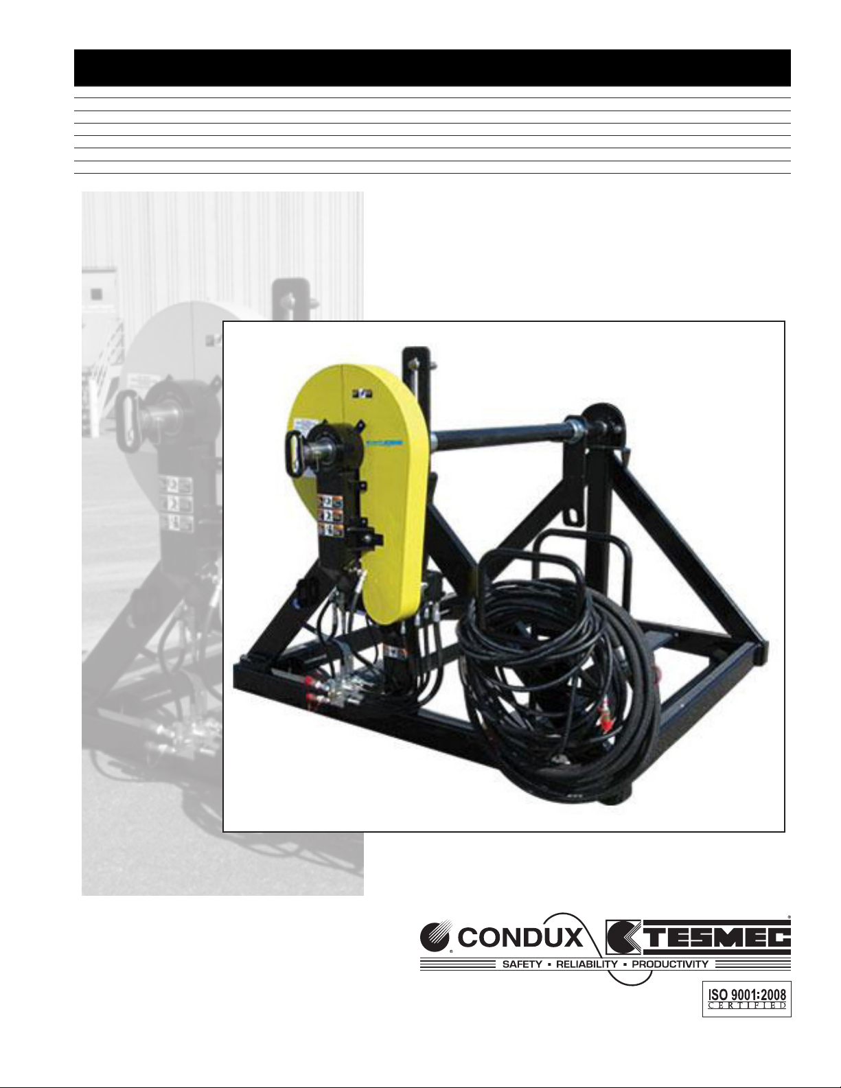
RS20/RS26 Reel Stand
Page 2
Important Safety Notice
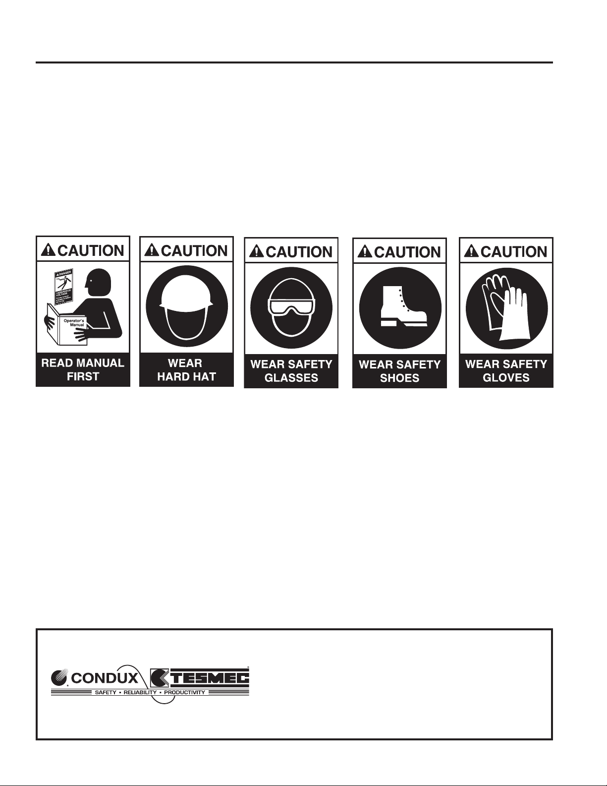
Before using a Condux Tesmec RS20/RS26 Reel Stand, operators must read and understand all procedures and safety instructions. Note all safety information on this page, and note specific safety requirements as explained by the procedures in this manual.
Failure to follow these instructions could result in serious personal injury or death.
ADVERTENCIA:
Favor de leer y comprender todas las instucciones de operación y seguridad antes de usar la máquina. Si
Ud. No comprende las instrucciones favor de consultarle a su jefe.
Save this user’s guide for future reference.
COMMUNICATION WITH THE MANUFACTURER:
For information related to the machine (use, maintenance, spare parts), always state the Model Number,
Serial Number, Manufacturing Year, and Order Number. This information can be found in the
Parts-Identification Table.
Manufacturer:
Condux Tesmec, Inc.
145 Kingswood Drive, Suite 1
Mankato, MN 56002-0668
1-507-387-6576
Fax 1-507-387-3855
E-mail: info@conduxtesmec.com
For questions on:
SAFETY - OPERATIONS - APPLICATIONS
CALL 1-877-854-1750
2
Page 3

IMPORTANT SAFETY NOTICE ..............................................2
COMMUNICATION WITH THE MANUFACTURER ...............2
1
GENERAL INFORMATION ..................................................... 4
A. PRODUCT DESCRIPTION ...............................................4
B. SAFETY INFORMATION ..................................................4
C. OPERATOR INFORMATION ..........................................4
D. GENERAL MAINTENANCE INFORMATION ................4
E. MACHINE USAGE ............................................................5
F. RESPONSIBILITY .............................................................5
G. OPERATORS MANUAL ................................................5
TECHNICAL SPECIFICATIONS ..............................................6
2
SAFETY CONDITIONS ............................................................6
3
A. SAFETY DEVICES ............................................................6
B. PERIODIC OPERATIONS ................................................6
C. CAUTIONS & WARNINGS ...............................................7
D. PULLING ROPE FAILURE ...............................................7
E. ROTATING COMPONENT, PINCH-POINT HAZARDS ..7
F. CRUSHING INJURY WHEN LOADING OR UNLOADING
ROPE OR CONDUCTOR REELS ....................................7
G. ELECTROSTATIC DISCHARGES ...................................7
H. INHALATION ENGINE EXHAUSTING GAS. ...................7
4
TRANSPORTING .....................................................................8
A. MACHINE LIFTING ...........................................................8
B. PACKING FOR SHIPMENT .............................................8
C. UNPACKING .....................................................................8
D. TOWING ............................................................................8
5
OPERATING PROCEDURES ..................................................8
A. INITIAL SET-UP ................................................................8
B. REEL INSTALLATION ...................................................10
Table of Contents
6
PARTS
............................................................................... 14-31
A. REPLACEMENT LABELS ........................................ 14-15
B. RS20 REEL STAND ASSY.........................................16-17
C. RS26 REEL STAND ASSY.........................................18-19
D. CHAIN DRIVE DETAIL ............................................. 20-23
E. HYDRAULIC DRIVE DETAIL ................................... 24-27
F. HYDRAULIC HAND PUMP........................................ 28-31
G. HYDRAULIC CONTROL VALVE............................... 32-33
H. CHAIN GUARD.......................................................... 34-35
I. HOSE RACK/GROUND ATTACHMENT.................... 36-37
J. HYDRAULIC HOSE DETAIL........................................... 38
K. CONTROL VALVE DETAIL.............................................. 39
7
NOTES ............................................................................... 30-31
3
Page 4

1.
General Information
A. PRODUCT DESCRIPTION
The RS20 Reel Stand provides up to 20,000 lbs of load capacity. The RS26 Provides
upt to 26,000lbs of load cpapacity. both come equipped with a hydraulic negative
brake, reel arbor bar and hose storage.
B. SAFETY INFORMATION
▪ Only trained and qualied operators should use this machine.
▪ Qualied operators are those persons who have received training from the ma-
chine owner’s company or, alternatively, from the manufacturer.
▪ This machine must be used only for the work it was designed for.
▪ This machine should not be used with unauthorized personnel on the work site.
▪ For any questions regarding operation, function, maintenance, etc., contact the
After-Sales Service of the manufacturer.
C. OPERATOR INFORMATION
▪ Operators must be aware of all local, state and federal safety regulations gov-
erning the use of this equipment.
▪ Operators must wear suitable clothing to reduce the possibility of entanglement
in the machine’s moving parts. They should avoid the wearing of chains, and
other jewelry for the same reason.
▪ Operators must use personnel protective gear (i.e. gloves, boots, helmet, etc.).
▪ Operators must carefully follow hazard related instructions contained in this
instruction manual or indicated on the machine.
▪ This machine’s work area should be free as possible of oil or other liquid spills
as well as materials or equipment that may be considered as an obstacle to
proper operation.
D. GENERAL MAINTENANCE INFORMATION
▪ It is absolutely forbidden to carry out any maintenance, or adjust any settings
on this machine while pulling (except for those indicated in this manual).
▪ Before carrying out any maintenance stop the machine (except for those in-
stances indicated otherwise in this manual) and wait till the system components
subject to heating have cooled sufciently.
▪ All the maintenance performed on this machine must be carried out on a level
surface and while the system is not under load.
▪ Authorized and trained personnel must perform all of the maintenance, both
scheduled maintenance and repair.
▪ Authorized and trained personnel are those persons who have received training
on the maintenance of this equipment from the machine owner’s company or,
as alternative, from the manufacturer.
4
Page 5

▪ Maintenance personnel must wear suitable clothes to reduce the possibility of
entanglement in the machine’s moving parts. They should avoid the wearing of
chains, and other jewelry for the same reason. Operators must use personal
protective gear (i.e. gloves, booths, helmet, etc.).
▪ All maintenance operations, both scheduled and repair must be carried out
per the instructions included in this manual or following technical instructions
provided by the manufacturer. Failure to follow these instructions relieves the
manufacturer from any responsibility and voids their warranty.
E. MACHINE USAGE
▪ The machine must not be used for the following:
▪ For lifting person and/or goods.
▪ For tensioning or pulling.
▪ In a location where the machine cannot be positioned and anchored in a proper
way.
▪ In areas with brush or other materials that can be easily set on re.
▪ In closed/unventilated sites or those poorly ventilated (tunnel or similar).
▪ At sites where fuels or explosives are present.
▪ For structure demolition.
▪ For the pulling of elastic elements.
▪ With over-ridden or broken safety system devices.
▪ For handling trucks or other movable equipment.
F. RESPONSIBILITY
Use of the reel stand in situations different from those indicated (Typology and using
eld), or not described in this manual, is to be considered extremely dangerous and/
or forbidden. Persons not using recommended restraints cause a situation of improper
use, and relive the manufacturer from any responsibility for accidents, injuries to persons or damage to property. The manufacturer’s warranty is also voided. Similarly the
manufacturer’s responsibility ends when the following situations occur:
▪ Tampering and/or modifying of the system without the manufacturer’s written
acceptance (in this case the operator becomes the manufacturer assuming all
obligations and responsibilities, both civil and penal).
▪ The use of non-original spare parts.
▪ Poor maintenance.
▪ Use with disconnected or over-ridden safety devices.
▪ For the connection to machine and/or plans not produced and not directly au-
thorized by the manufacturer in a written acceptance.
G. OPERATORS MANUAL
▪ Information contained in this manual applies to all the operators charged with
the use and/or the maintenance of this machine
5
Page 6
2.
▪ This instruction manual is not a training manual
▪ Before using the machine the job site supervisor and the operators must read
this instruction manual.
▪ All operators user must carefully follow the instructions contained in this manual
▪ Before using the machine the operator must know the positions and the opera-
tion of all controls.
▪ The job site supervisor must verify that the instructions contained in this manual
are applied.
▪ This instruction manual must be kept with the machine, for the entire life of the
machine, so it is available to all potential users and operators.
▪ The instruction manual must be kept in a sheltered and dry place.
Technical Specications
The Condux Tesmec RS20/RS26 Reel Stands were developed for paying in or out
conductor reels when used in conjunction with Condux Tesmec Puller-Tensioners and
Tensioners. Industry leading features like Self Acting Hydraulic Brake and Advanced
Hydraulic
3.
General Specications RS20 RS26
Reel OD Capacity 102 inches 102 inches
Reel Width Capacity 70 inches 72 inches
Weight Capacity 20,000 lbs 26,000 lbs
Total Weight (Skid Mounted) 2,600 lbs 2,600 lbs
Systems.
Safety Information
A. SAFETY DEVICES
Machine has been equipped with the following safety devices:
▪ A mechanical negative safety brake that stops all movement if hydraulic
pressure is lost.
▪ Where possible, guards and covers are provided to protect personnel from the
moving parts.
!DANGER: It is absolutely forbidden to use this machine with protective
guards removed or with damaged or disconnected safety devices.
B. PERIODIC OPERATIONS
Proper functioning of safety systems should be veried daily.
!CAUTION: Any customer alterations to the provided safety devices relieves
6
the manufacturer of any responsibility for any resulting damage of property or injury to
personnel.
Page 7

C. CAUTIONS & WARNINGS
When operating this machine users must be aware of other risks associated with the
work for which the machine is intended.
D. PULLING ROPE FAILURE
Obviously this will cause uncontrolled movement of the entire machine. Both this and
the danger then presented by the pulling rope and/or conductor can cause serious
injury or death.
To reduce operator exposure to these dangers owners must:
▪ Regularly check the rope and replace it as soon as defects or signs of wear are
detected.
▪ Assume only the recommended operation positions indicated in this manual.
E. ROTATING COMPONENT, PINCH-POINT HAZARDS
Due to the nature of the work being preformed and important system functionality, it is
possible to fully guard all rotating components. To minimize risks operators must:
▪ Avoid any contact with the machine’s rotating components.
▪ Follow the anchoring instructions described in this manual.
▪ Follow all recommendations in this manual regarding the use of personal safety
equipment.
F. CRUSHING INJURY WHEN LOADING OR UNDLOADING ROPE OR
CONDUCTOR REELS
Operators must know the proper methods for executing these tasks and should be
trained to do them properly.
G. ELECTROSTATIC DISCHARGES
To reduce the risk presented by static electric charge build up in the ropes and conduc-
tors during pulling operations, the machine must be properly grounded. T
o minimize
these risks operators must:
▪ Be trained in, and apply, the proper methods used to ground the machine
before using the machine.
H. INHALATION ENGINE EXHAUSTING GAS
To minimize these risks operators must:
▪ Assume the proper operating position during operation and use appropriate
safety equipment as needed.
7
Page 8
4.
Transporting
A. MACHINE LIFTING
For machine lifting use only devices (overhead traveling cranes, lift trucks, ropes,
cables, hooks, etc.) with a capacity equal to the weight to be lifted. Personnel should
not be on the machine when it is lifted.
!DANGER: Failure to follow the recommendations in this section may create a dangerous situation and/or damage to the machine. The manufacturer’s warranty may also become void as a result.
B. PACKAGING FOR SHIPMENT
Transport by land or truck. Certain surfaces may be protected by cardboard and/or ply-
wood and/or polyethylene lm. To prevent movement, use nailed wheel chocks. Attach
the machine to the oor of a truck box or trailer using chains and hooks at the attach-
ment points provided.
C. UNPACKING
When receiving the machine verify the condition of the package; immediately notify
the transportation company and the manufacturer (use photos whenever possible) of
any damage that may have occurred during shipment. Verify that the supplied product
matches that which was ordered; immediately advise the manufacturer if there is a
discrepancy. Use caution when unpacking to avoid damaging the product.
5.
!CAUTION: Disposal of all packaging materials must be in accordance with
local regulations.
D. TOWING
This machine is designed for towing at highway speeds. No personnel may ride on the
machine at any time while towing the machine at ANY speed.
!CAUTION: Always make sure to hook safety chains, attach lights & safety
brake to transporting vehicle before towing machine.
Operating Procedures
!WARNING: the “Freewheel” mode is to be used only for positioning the
reel/drum for loading and unloading. the reel stands are designed to slowly
bleed off pressure form the negative brake for safety reasons. Using the
freewheel mode for extended rotations of the reel/drum can result in dam
age to the negative brake and motor.
It is essential that the RS20 or RS26 are properly set up before operation. Using the
following procedure will allow the unit to be set up in a short period of time and yield
optimum performance.
A. INITIAL SET-UP
1. Locate RS20 or RS26 Reel Stand at least 20-30 feet behind the stringing equip-
8
ment as the site allows
Page 9

2. Securely anchor using the anchor points provided ( Figure 1)
3. Properly ground the reel stand using the grounding connections provided
(Figure 2)
4. Connect the hydraulic hoses to the stringing machine (Figure 3)
5. Secure the area between the stringing equipment and this reel stand to limit
personnel entry.
Figure 1. Anchoring Bracket Figure 2. Grounding Lug
Figure 3. Connecting Hydraulic Hoses
9
Page 10
B. REEL INSTALLATION
10
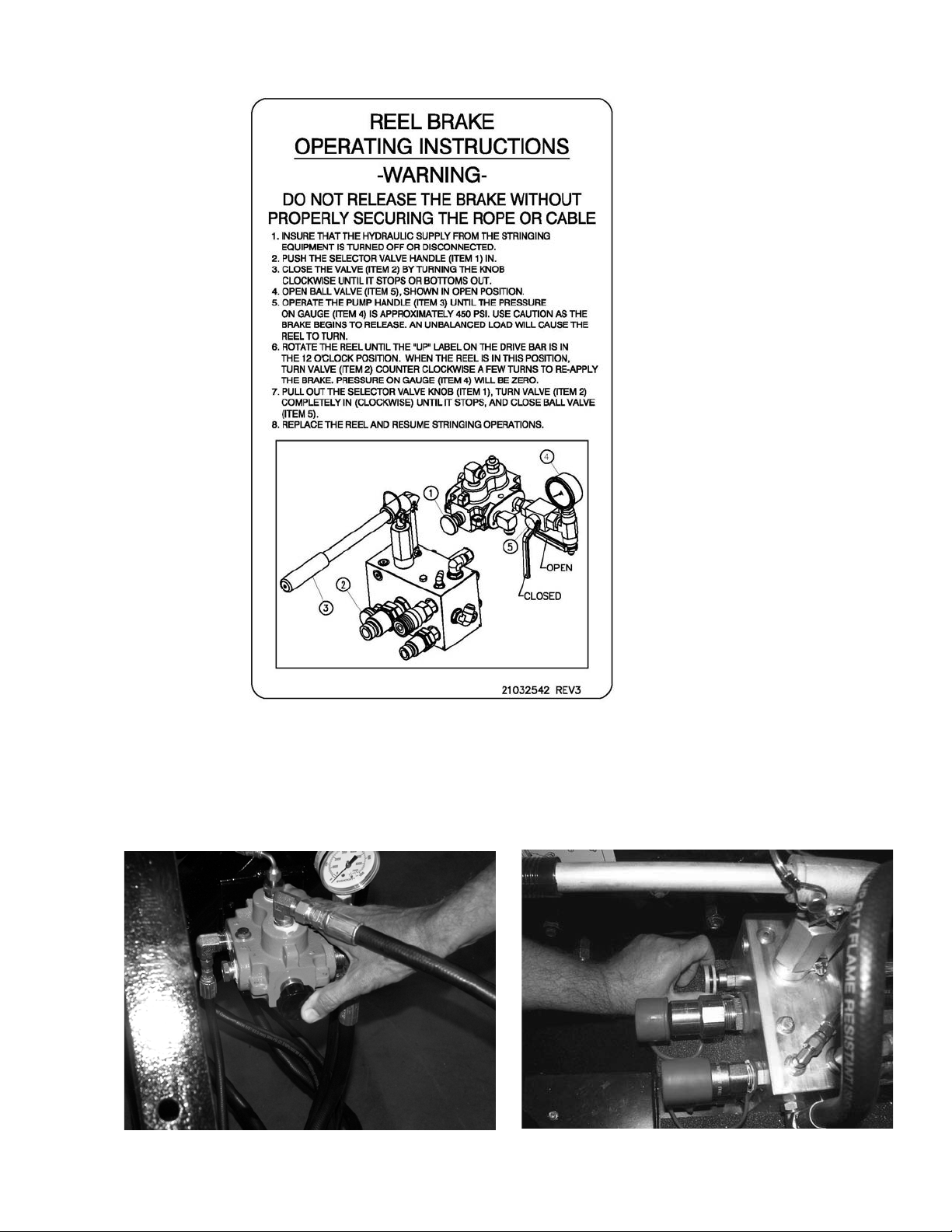
1. Ensure that the hydraulic supply from the stringing equipment is shut-off
2. Push in the selector valve handle (Figure 4)
3. Close the valve (clockwise) on the pump (Figure 5)
Figure 4. Push in Selector Valve Handle
Figure 5. Close Valve on Pump
Page 11
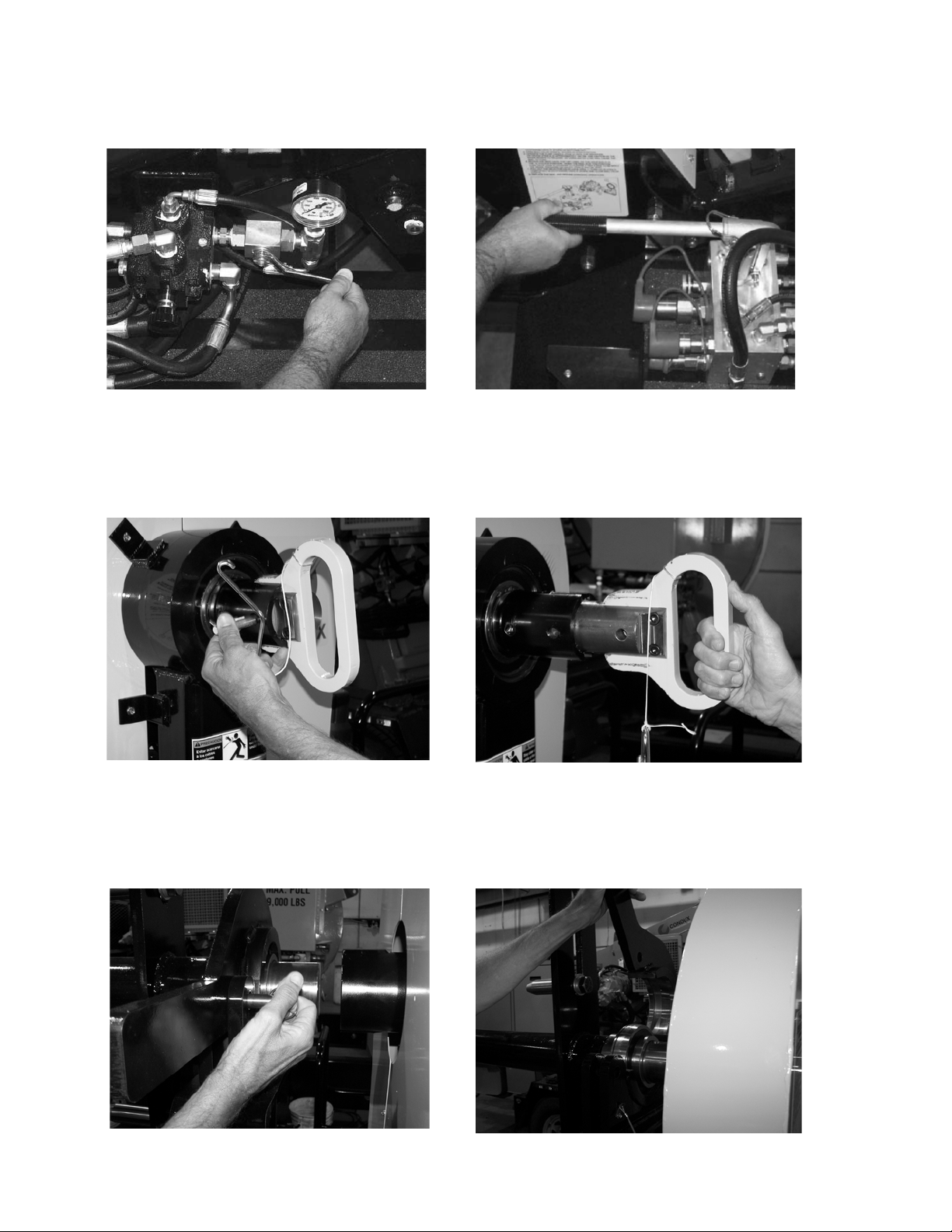
4. Open the Ball Valve (in line with) as shown (see Figure 6)
5. Operate the pump handle until the pressure on the gauge reads approximately
450 PSI. Use caustion as the brake begins to release as the arbor bar will
begin to rotate. (Figure 7)
Figure 6. Open Ball Valve
Figure 7. Pump Handle until Gauge Reads
450 PSI
6. Disengage drive side pin by removing keeper pin and pulling out the drive pin.
(Figure 7 & 8)
Figure 7. Remove Keeper Pin from Drive Pin Figure 8. Pull Out Drive Pin
7. Remove bearing retainer pin and lift hinged keeper to fully open position.
(Figure 9 & 10)
Figure 9. Remove Retainer Pin from Bearing
Keeper
Figure 10. Open Bearing Keeper to Fully
Open Position
11
Page 12
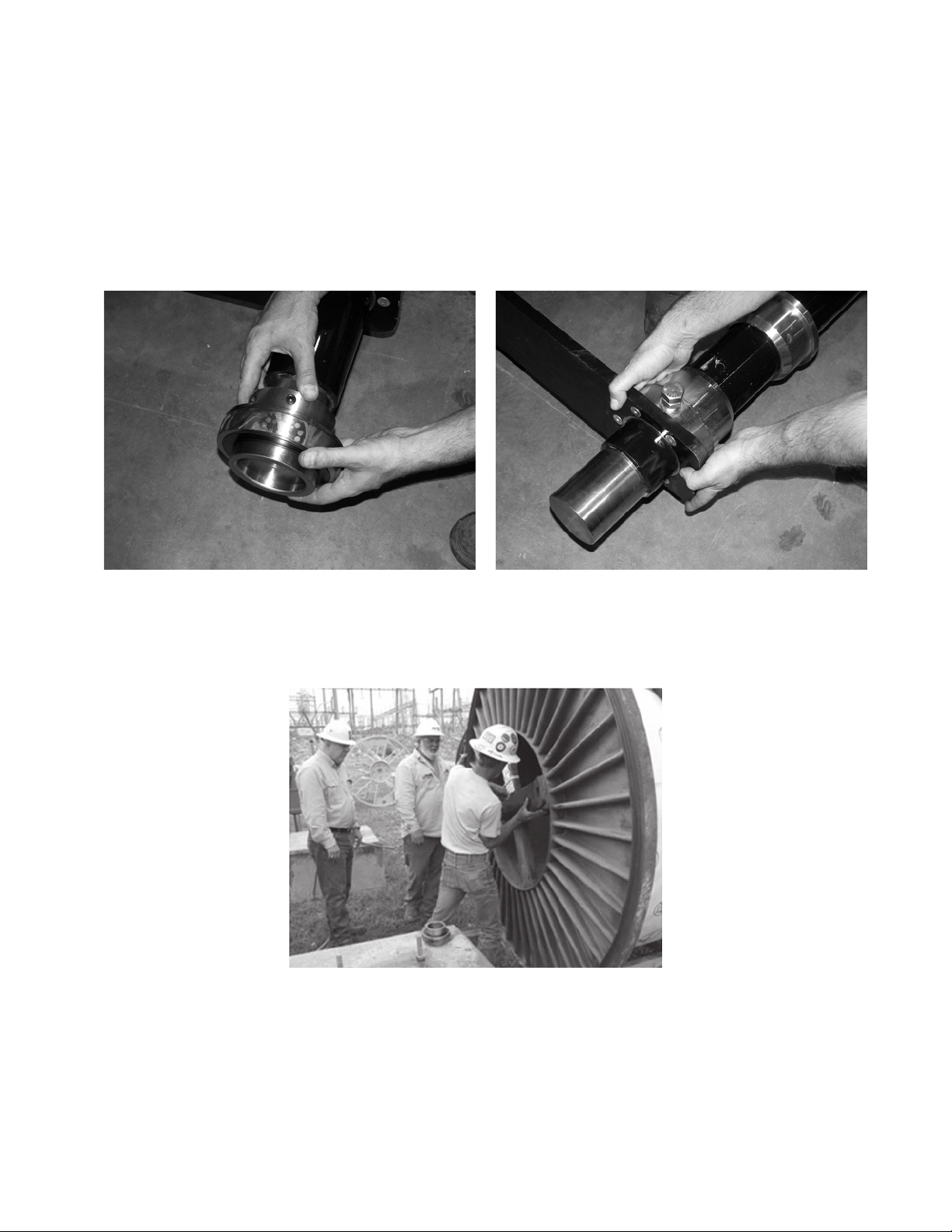
8. Repeat number 6 on other side.
9. Remove arbor bar.
10. Remove bearing from arbor bar. (Figure 11)
11. Remove Lifting Bracket using a 1-1/8” wrench (Figure 12)
12. Install Arbor Bar through the reel hole ensuring drive pins engage drive holes
(Figure 14).
Figure 11. Remove Bearing Figure 12. Remove Ling Bracket
Figure 13. Install Arbor Bar
12
Page 13
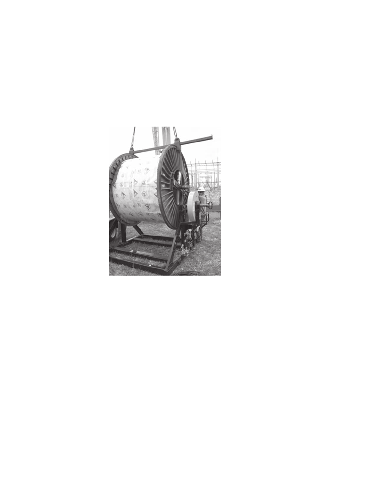
13. Reverse steps 9 through 11 to install components back onto arbor bar.
14. Once arbor has been secured to the reel, lift the reel utilizing the lifting brackets
and install onto reel stand. (Figure 14)
15. Reference operational label located on the reel stand for brake release.
Figure 14. Load Reel
13
Page 14

6.
Parts
CONDUX TESMEC, INC., REEL STAND
REPLACEMENT LABELS
21032700
ITEM PART NO DESCRIPTION QTY
1 02266200 STRIP,ANTI-SLIP FO TRAILER 4
2 02269300 LABEL,WARNING-READ MANUAL 2X6 1
3 02269303 LABEL,WARNING-HYD FLUID 2X6 1
4 02269603 LABEL,WARNING-CAPSTN CATCH 2X6 2
5 02269604 LABEL,WARNING-CABLE TENSION 2X6 2
6 02269731 LABEL,WARNING-STAY CLR 1.5 X 4.5 1
7 02289355 LABEL,LIFT POINT ISO STD 4
8 02289499 TAPE,ABRASIVE ANTISLIP 2IN X 80IN 2
9 02289504 SCREW,DRIVE #4 X 0.375 SS 4
10 02289636 DECAL,CONDUX LOGO BLUE/CLEAR 1
11 02289640 LABEL,GROUND - ISO 1.5 X 1.5 2
12 02289740 TAG,METAL SERIAL NUMBER 1
13 21032542 LABEL,INST-REEL LOADING URW24 1
14
Page 15

CONDUX TESMEC, INC., REEL STAND
REPLACEMENT LABELS
21032700
ITEM PART NO DESCRIPTION QTY
1 02266200 STRIP,ANTI-SLIP FO TRAILER 4
2 02269300 LABEL,WARNING-READ MANUAL 2X6 1
3 02269303 LABEL,WARNING-HYD FLUID 2X6 1
4 02269603 LABEL,WARNING-CAPSTN CATCH 2X6 2
5 02269604 LABEL,WARNING-CABLE TENSION 2X6 2
6 02269731 LABEL,WARNING-STAY CLR 1.5 X 4.5 1
7 02289355 LABEL,LIFT POINT ISO STD 4
8 02289499 TAPE,ABRASIVE ANTISLIP 2IN X 80IN 2
9 02289504 SCREW,DRIVE #4 X 0.375 SS 4
10 02289636 DECAL,CONDUX LOGO BLUE/CLEAR 1
11 02289640 LABEL,GROUND - ISO 1.5 X 1.5 2
12 02289740 TAG,METAL SERIAL NUMBER 1
13 21032542 LABEL,INST-REEL LOADING URW24 1
15
Page 16

CONDUX TESMEC INC.,
RS20 REEL STAND ASSY (20000LBS)
16
Page 17

21032700 RS20 REEL STAND ASSY (20000LBS)
ITEM PART NO DESCRIPTION QTY
1 02036601CT 3/4-10 X 4.00 HEX HD CAPSCREW GR8 YZ 2
2 02123904CT 3/4 FLATWASHER TYPEA W CZ 4
3 02129105CT 3/4-10 X 2.00 HEX HD CAPSCREW SS T316 2
4 02200600CT 3/4-10 NYLOC NUT GR5 CZ 10
5 02202701CT 1.00 LOCKWASHER REG CZ 2
#10-24 X 0.50 HEX FLANGE HD CAPSCREW GR5
6 02266400CT
CZ 2
7 02288518CT 3/4 FLATWASHER TYPEA NARR CZ 16
8 02289465CT 1.00-08 X 2.50 HEX HD CAPSCREW GR8 YZ 2
9 02289600CT 3/4-10 HEX JAM NUT CZ 2
10 02289601CT 3/4-10 X 2.25 HEX HD CAPSCREW GR5 CZ 8
11 02289700CT BEARING,MBB 3.500 6.299 3.781 2
12 02289729CT 3/4 X 2.50 QUICK RELEASE PIN 2
13 02290123CT 4IN SHAFT COLLAR-2 PIECE 1
14 02290601CT 1.00 FENDER WASHER CZ 2
15 02290619CT LABEL,MAX LOAD CAP 20000 LBS 4
16 21032541 LABEL,UP DIRECTIONAL URW24 2
17 21032730 4IN ARBOR BAR ASSY - RS20 1
18 21032734 LIFT PLATE ASSY 1
19 21032753 DRUM DRIVE STUD 2
20 21032786 BEARING SADDLE ASSY - RS20 2
21 21032795 4IN DRUM PILOT HUB-NYLON 1
22 21032700SUB REEL STAND-SUBASSY RS20/26 1
17
Page 18

CONDUX TESMEC INC.,
RS26 REEL STAND ASSY (26000LBS)
18
Page 19

21034200 RS26 REEL STAND ASSY (26000 LB)
ITEM PART NO DESCRIPTION QTY
1 02036601CT 3/4-10 X 4.00 HEX HD CAPSCREW GR8 YZ 2
2 02123904CT 3/4 FLATWASHER TYPEA W CZ 4
3 02129105CT 3/4-10 X 2.00 HEX HD CAPSCREW SS T316 2
4 02200600CT 3/4-10 NYLOC NUT GR5 CZ 10
5 02202701CT 1.00 LOCKWASHER REG CZ 2
6 02266400CT #10-24X0.50 HEX FLANGE HD CAPSCREW GR5 CZ 2
7 02288518CT 3/4 FLATWASHER TYPEA NARR CZ 16
8 02289465CT 1.00-08 X 2.50 HEX HD CAPSCREW GR8 YZ 2
9 02289600CT 3/4-10 HEX JAM NUT CZ 2
10 02289601CT 3/4-10 X 2.25 HEX HD CAPSCREW GR5 CZ 8
11 02289729CT 3/4 X 2.50 QUICK RELEASE PIN 2
12 02290601CT 1.00 FENDER WASHER CZ 2
13 02290608CT BEARING,MBB 100MM 180MM 98.4MM 2
14 02290609CT 4IN SHAFT COLLAR-HEAVY 1
15 02290620CT LABEL,MAX LOAD CAP 26000 LBS 4
16 21032541 LABEL,UP DIRECTIONAL URW24 2
17 21032734 LIFT PLATE ASSY 1
18 21032753 DRUM DRIVE STUD 2
19 21032795 4IN DRUM PILOT HUB-NYLON 1
20 21034220 4IN ARBOR BAR ASSY - RS26 1
21 21034221 BEARING SADDLE ASSY - RS26 2
22 21032700SUB REEL STAND-SUBASSY RS20/26 1
19
Page 20

CONDUX TESMEC INC.,
CHAIN DRIVE DETAIL - REEL STAND ASSY
20
Page 21

CHAIN DRIVE DETAIL - REEL STAND ASSY
RS20 - SERIAL NO AK269 AND LATER
RS26 - SERIAL NO AR*** AND LATER
ITEM PART NO DESCRIPTION QTY
1 02021301CT 1/2 FLATWASHER TYPE A WIDE CZ 2
2 02038401CT 1/2-13 X 1.50 HEX HD CAPSCREW GR8 YZ 4
3 02125106CT 3/4-10 HEX NUT 304SS 1
4 02208300CT 1/2 X 3.50 SNAP LOCK PIN 1
5 02222000CT 1/4-28 GREASE ZERK STRAIGHT 1
6 02234100CT 3/8-16 X 1.50 SOCKET HD CAPSCREW 2
7 02287310CT 1/2 EXT RETAINING RING 1
8 02288230CT 3/8 FLATWASHER TYPE A NARR CZ 2
9 02288419CT 3/8-16 NYLOC NUT GR2 CZ THIN 1
10 02288457CT 1.0 FLATWASHER TYPE A NARR CZ 2
11 02288876CT LANYARD 1
12 02289525CT M12-1.75 X 35 HEX HD CAPSCREW 8.8 CZ 1
13 02289585CT IDLER SPROCKET 1
14 02289588CT DGB BEARING(SEALED) - 90ID X 160OD 2
15 02289592CT 3 1/2 EXT RETAINING RING 1
16 02289680CT BRAKE/MOTOR ASSY 1
17 02289701CT #80 ROLLER CHAIN X 96LINK 1
18 02289705CT 6 1/2 INT RETAINING RING 2
19 02289734CT 1.0-14 NYLOC NUT GR2 CZ THIN 2
20 02290221CT 3/8-16 X 6.00 HEX HD CAPSCREW GR2 CZ 1
21 12010600CT 1/2 LOCKWASHER CZ 5
22 21032573 DRIVE SPROCKET RETAINER 1
23 21032719 #80 X 58T DRIVE SPROCKET 1
24 21032722 REEL DRIVE SHAFT 1
25 21032726 REEL DRIVE SHAFT HANDLE 1
26 21032746 MOTOR DRIVE SPROCKET 1
27 21032779 TENSION ADJUSTMENT SHAFT 2
28 21032780 IDLER SPROCKET SHAFT 1
29 21032781 IDLER SPROCKET ADJUSTMENT SADDLE 1
30 21032782 IDLER SPROCKET ADJUSTMENT SHAFT 1
21
Page 22

CONDUX TESMEC INC.,
CHAIN DRIVE DETAIL - REEL STAND ASSY
22
Page 23

CHAIN DRIVE DETAIL - REEL STAND ASSY
RS20 - SERIAL NO AK268 AND EARLIER
RS26 - SERIAL NO AR*** AND EARLIER
ITEM PART NO DESCRIPTION QTY
1 02021301CT 1/2 FLATWASHER TYPEA WIDE CZ 1
2 02038401CT 1/2-13 X 1.50 HEX HD CAPSCREW GR8 YZ 4
3 02125104CT 1/2-13 HEX NUT SS T316 1
4 02208300CT 1/2 X 3.50 LG SNAP LOCK PIN 1
5 02222000CT GREASE ZERK-SHORT STR 1/4-28 1
6 02234100CT 3/8-16 X 1.50 SOCKET HD CAPSCREW ALY PL 2
7 02288262CT 3/8 NYLON FLATWWASHER 1
8 02288419CT 3/8-16 NYLOC NUT THIN GR2 CZ 1
9 02288457CT 1.00 FLATWASHER TYPEA NARR CZ 1
10 02288876CT LANYARD, ALL UNIVER COUPLINGS 1
11 02289525CT M12-1.75 X 35 HEX HD CAPSCREW 8.8 CZ 1
12 02289585CT IDLER SPROCKET HB80A12 X 3/4 1
13 02289588CT BEARING,DGB 90 ID 160MM OD SLD 2
14 02289592CT 3 1/2 EXT RETAINING RING 1
15 02289680CT BRAKE ASSY W/MOTOR 1
16 02289701CT CHAIN,#80-1PTCH 96PTCHS SGL 1
17 02289705CT 6 1/2 INT RETAINING RING 2
18 02289734CT 1.00-14 NYLOC NUT THIN GR2 CZ 1
19 12010600CT 1/2 LOCKWASHER REGULAR CZ 5
20 21032573 DRIVE SPROCKET RETAINER-DANFOSS 1
21 21032719 DRIVE SPROCKET - #80 X 58T 1
22 21032722 REEL DRIVE SHAFT 1
23 21032726 REEL DRIVE SHAFT HANDLE 1
24 21032746 MAIN DRIVE HUB - REEL STAND 1
25 21032772 TENSIONER ADJUSTMENT SHAFT 1
26 21032774 ADJUSTMENT SCREW - CHAIN TENSIONER 1
23
Page 24

CONDUX TESMEC INC.,
HYDRAULIC DRIVE- REEL STAND ASSY
24
Page 25

HYDRAULIC DRIVE DETAIL - REEL STAND ASSY
RS20 - SERIAL NO AK320 AND LATER
RS26 - SERIAL NO AR*** AND LATER
ITEM PART NO DESCRIPTION QTY
1 02093600CT HYD FITTING - 08 NPT X 08 JIC 90EL 1
2 02198000CT HYD FITTING - 08 NPT HEX PLUG 1
3 02288231CT 5/16 FLATWASHER TYPE A NARR CZ 4
4 02288430CT 5/16-18 X 3.00 HEX HD CAPSCREW GR5 CZ 2
5 02288492CT 5/16-18 X 6.00 HEX HD CAPSCREW GR5 CZ 2
6 02289565CT HYD FITTING - 08 JIC X 06 BSPP 1
7 02289608CT HYD FITTING - 08 NPT X 04 JIC 90EL 1
8 02289680CT BRAKE/MOTOR ASSY 1
9 02289681CT HYD FITTING - 12 JIC X 12 BSPP 1
10 02289682CT HYD FITTING - 08 JIC X 12 BSPP 1
11 02289684CT HYD FITTING - 04 JIC X 04 BSPP 90EL 1
12 02289711CT 1/2 NPT SITE GAUGE 1
13 02289712CT 1/2 NPT BREATHER VENT 1
14 12002300CT 5/16-18 NYLOC NUT GR5 CZ 4
15 21032775 CONTROL VALVE ASSY-REEL STAND 1
16 21034215 MANIFOLD ASSY-REEL STAND 1
25
Page 26

CONDUX TESMEC INC.,
HYDRAULIC DRIVE- REEL STAND ASSY
26
Page 27

HYDRAULIC DRIVE DETAIL - REEL STAND ASSY
RS20 - SERIAL NO AK319 AND EARLIER
RS26 - SERIAL NO AR*** AND EARLIER
ITEM PART NO DESCRIPTION QTY
1 02093600 HYD FITTING 08 NPT (M) X 08 JIC (M) 90EL 1
2 02198000 HYD FITTING 08 NPT (M) HEX PLUG 1
3 02288231 5/16 FLATWASHER TYPEA-NARR CZ 4
4 02288430 5/16-18 X 3.00 HEX HD CAPSCREW GR5 CZ 2
5 02288492 5/16-18 X 6.00 HEX HD CAPSCREW GR5 CZ 2
6 02289565 HYD FITTING 08 JIC X 06 BSPP W/ SEAL 1
7 02289608 HYD FITTING 08 NPT (M) X 04 JIC (M) 90EL 1
8 02289680 BRAKE ASSY W/MOTOR-PAINTED 1
9 02289681 HYD FITTING 12 JIC X 12 BSPP W/SEAL 1
10 02289682 HYD FITTING 08 JIC X 12 BSPP W/SEAL 1
11 02289684 HYD FITTING 04 JIC X 04 BSPP W/SEAL 90EL 1
12 02289711 SITE GAUGE-GLASS 1/2-14NPT 1
13 02289712 HYD FITTING 08 NPT BREATHER VENT 1
14 12002300 5/16-18 NYLOC NUT GR5 CZ 4
15 21032765 MANIFOLD ASSY - REEL STAND 1
16 21032775 CONTROL VALVE ASSY-REEL STANDS 1
27
Page 28

CONDUX TESMEC INC.,
HYD HAND PUMP MANIFOLD
28
Page 29

21034215 HYD HAND PUMP MANIFOLD - REEL STAND ASSY
RS20 - SERIAL NUMBER AK320 AND LATER
RS26 - SERIAL NUMBER AR*** AND LATER
ITEM PART NO DESCRIPTION QTY
1 02045904CT HYD FITTING 04 O-RING PLUG 5
2 02094200CT HYD FITTING 08 O-RING X 08 JIC 90EL 3
3 02127000CT HYD FITTING 04 O-RING X 04 JIC 90EL 11
4 02269600CT HYD FITTING 08 O-RING X 08 NPT 2
5 02269688CT 1/4 X 1 3/8 QUICK PIN 2
6 02269692CT HYD FITTING 04 O-RING X 04 JIC 2
7 02288687CT HYD FITTING 08 O-RING X 08 JIC 2
8 02288740CT HYD FITTING 12 O-RING X 12 JIC 1
9 02289615CT QUICK COUPLER MALE - 1/2 NPT 1
10 02289617CT PROTECTIVE CAP - MALE QUICK COUPLER 1
11 02289626CT PROTECTIVE CAP - FEMALE QUICK COUPLER 1
12 02289627CT PROTECTIVE CAP - MALE QUICK COUPLER 1
13 02289632CT QUICK COUPLER FEMALE - 1/2 NPT 1
14 02289715CT QUICK COUPLER MALE - 1IN NPT 1
15 02289716CT HYD FITTING 12 O-RING X 16 NPT 1
16 02289718CT NEEDLE CARTRIDGE VALVE 1
17 02290036CT RELIEF CARTRIDGE VALVE - 750PSI 1
18 02290607CT HAND PUMP HANDLE 1
19 21034213 HAND PUMP VALVE ASSY 1
20 21034214 MANIFOLD BLOCK 1
29
Page 30

CONDUX TESMEC INC.,
HYD HAND PUMP MANIFOLD
30
Page 31

21032765 HYD HAND PUMP MANIFOLD - REEL STAND ASSY
RS20 - SERIAL NUMBER AK319 AND EARLIER
RS26 - SERIAL NUMBER AR*** AND EARLIER
ITEM PART NO DESCRIPTION QTY
1 02045904CT HYD FITTING 04 O-RING PLUG 5
2 02094200CT HYD FITTING 08 O-RING X 08 JIC 90EL 3
3 02127000CT HYD FITTING O4 O-RING X 04 JIC 90EL 1
4 02269600CT HYD FITTING 08 O-RING X 08 NPT 2
5 02269692CT HYD FITTING 04 O-RING X 04 JIC 2
6 02288687CT HYD FITTING 08 O-RING X 08 JIC 2
7 02288740CT HYD FITTING 12 O-RING X 12 JIC 1
8 02289615CT COUPLER,QD-MALE 1/2IN NPT 1
9 02289617CT CAP,QD NIPPLE (M)-1/2IN BODY 1
10 02289626CT CAP,QD COUPLER (F)-1/2IN BODY 1
11 02289627CT CAP,QD NIPPLE (M)-3/4IN BODY 1
12 02289632CT COUPLER,QD-FEMALE 1/2IN NPT 1
13 02289715CT COUPLER,QD-MALE 1IN NPT 1
14 02289716CT HYD FITTING 12 O-RING X 16 NPT 1
15 02289717CT VALVE,CARTRIDGE-HAND PUMP-ASSY 1
16 02289718CT VALVE,CARTRIDGE-NEEDLE VALVE 1
17 02290036CT VALVE,CARTRIDGE-RELIEF 750PSI 1
18 21032766 BLOCK,MANIFOLD - REEL STAND 1
31
Page 32

CONDUX TESMEC INC.,
HYDRAULIC CONTROL VALVE
32
Page 33

HYD CONTROL VALVE - REEL STAND ASSY
21032775
ITEM PART NO DESCRIPTION QTY
1 02093600CT HYD FITTING 08 NPT (M) X 08 JIC (M) 90EL 2
2 02198000CT HYD FITTING 08 NPT (M) HEX PLUG 1
3 02286437CT HYD FITTING 08 NPT (M) X 04 NPT (F) 1
4 02289608CT HYD FITTING 08 NPT (M) X 04 NPT (F) 1
5 02289609CT HYD FITTING 08 NPT (M) X 04 JIC (M) 2
6 02289613CT PRESSURE GAUGE 0 - 1000PSI 1
7 02289641CT HYD FITTING 08 NPT (M) X 08 NPT (F) TEE 1
8 02289685CT HYD CONTROL VALVE 6WAY 2POS 1
9 02290111CT HYD CONTROL VALVE 2WAY 1
10 12003900 HYD FITTING 08 NPT (M) X 08 NPT (M) 1
33
Page 34

CONDUX TESMEC INC.,
CHAIN GUARD
34
Page 35

CHAIN GUARD - REEL STAND ASSY
21032700SUB
ITEM PART NO DESCRIPTION QTY
1 02266400CT #10-24X0.50 HEX FLANGE HD CAPSCREW GR5 CZ 18
2 02289639CT MANUAL HOLDER-WEATHERPROOF 1
3 21032732 CHAIN GUARD “A” 1
4 21032741 CHAIN GUARD “B” 1
5 21032744 BACK PLATE - CHAIN GUARD “B” 1
35
Page 36

CONDUX TESMEC INC.,
HOSE RACK/GROUND ATTACHMENT
36
Page 37

HOSE RACK/GROUND ATTACHMENT - REEL STAND ASSY
21032700SUB
ITEM PART NO DESCRIPTION QTY
1 02010100CT 1/2-13 NYLOC NUT GR5 CZ 2
2 02200600CT 3/4-10 NYLOC NUT GR5 CZ 8
3 02204301CT 3/8-16 X 2.25 HEX HD CAPSCREW GR8 YZ 4
4 02253600CT 1/2-13 X 1.75 HEX HD CAPSCREW GR5 CZ 2
5 02288230CT 3/8 FLATWASHER TYPE A NARR CZ 4
6 02288856CT 5/16 X 1.75 QUICK LOCK PIN 2
7 02290881CT 7/16 NEOPRENE SEAL WASHER 4
8 12008301CT 1/2 FLATWASHER TYPE A NARR CZ 4
9 12013500CT 3/8-16 NYLOC NUT GR5 CZ 4
10 21031050 PRESSURE RELIEF TOOL - HYD HOSE 1
11 21032755 HOSE RACK SUPPORT 1
12 21032760 HOSE RACK 1
13 21033919 BRASS GROUNDING BAR 4
37
Page 38

CONDUX TESMEC, INC., REEL STAND
HYDRAULIC HOSE DETAIL
PART NO DESCRIPTION QTY
02288689 1/2IN x 30IN LG Hose Assembly 1
02288692 1/2IN x 48IN LG Hose Assembly 1
02288697 3/4IN x 44IN LG Hose Assembly 1
02289720 1/4IN x 18IN Lg Hose Assembly 1
02289721 1/4IN x 26IN Lg Hose Assembly 2
02289722 1/4IN x 36IN Lg Hose Assembly 1
02289723 1/2IN x 22IN LG Hose Assembly 1
02289724 1/2IN x 40IN LG Hose Assembly 2
21032767 1/2IN x 50FT LG Feed Hose Assembly 1
21032768 1 IN x 50FT LG Return Hose Assembly 1
21032769 1/2IN x 50FT LG Case Drain Hose Assembly 1
21032770 1/2IN x 25FT LG Feed/Case Drain Hose Assembly EXT 1
21032771 1 IN x 25FT LG Return Hose Assembly EXT 1
38
Page 39

CONDUX TESMEC, INC., REEL STAND
HYDRAULIC HOSE DETAIL
PART NO 1st CONNECTION 2nd CONNECTION QTY
02288697 Motor Port "A" Manifold Port "E" 1
02289724 Motor Port "B" Manifold Port "D" 1
02289724 Motor Port "C" Manifold Port "F" 1
02289720 Motor Port "D" Valve Port "C" 1
02289723 Valve Port "E" Manifold Port "M" 1
02289721 Valve Port "A" Manifold Port "G" 1
02289721 Valve Port "B" Manifold Port "L" 1
Plugged Valve Port "F" 1
02288689 Valve Port "D" Manifold Port "C" 1
Tank Port "A" Fill/Breather Vent Port 1
Tank Port "B" Site Gauge Port
Plugged Tank Port "C" Drain Port
02289692 Tank Port "D" Manifold Port "H"
02289722 Tank Port "E" Manifold Port "I"
39
Page 40

NOTES41NOTES
40
Page 41

Page 42

Condux Tesmec, Inc., Incorporated extends the following warranty to the original purchaser of these
goods for use, subject to the qualications indicated:
Condux Tesmec, Inc., warrants to the original purchaser for use that the goods or any component
thereof manufactured by Condux Tesmec, Inc., will be free from defects in workmanship for a period of
1 year from the date of purchase, provided such goods are installed, maintained, and used in accordance with Condux Tesmec’s written instructions.
Components not manufactured by Condux Tesmec, Inc., but used within the assembly provided by Tesmec, Inc., are subject to the warranty period as specied by the individual manufacturer of said component, provided such goods are installed, maintained, and used in accordance with Condux Tesmec,
Inc., and the original manufacturer’s written instructions.
Condux Tesmec, Inc.’s sole liability and the purchaser’s sole remedy for a failure of goods under this
limited warranty, and for any and all claims arising out of the purchase and use of goods, shall be limited to the repair or replacement of the goods that do not conform to this warranty.
To obtain repair of replacement service under the limited warranty, the purchaser must contact the fac-
tory for a Return Material Authorization (RMA), Once obtained, send the RMA along with the defective
part or goods, transportation prepaid, to:
Condux Tesmec, Inc.
145 Kingswood Drive • Suite 1
Mankato, MN 56002 USA
THERE ARE NO EXPRESS WARRANTIES COVERING THESE GOODS OTHER THAN AS SET
FORTH ABOVE. THE IMPLIED WARRANTIES OR MERCHANTABILITY AND FITNESS FOR PARTICULAR PURPOSE ARE LIMITED IN DURATION TO ONE YEAR FROM DATE OF PURCHASE.
CONDUX TESMEC, INC., ASSSUMES NO LIABILITY IN CONNECTION WITH THE INSTALLATION
OR USE OF THIS PRODUCT, EXCEPT AS STATED IN THIS LIMITED WARRANTY, CONDUX TESMEC, INC., WILL IN NO EVENT BE LIABLE FOR INCIDENTAL OR CONSEQUENTIAL DAMAGES.
Condux Tesmec, Inc.
P.O. Box 668 • 145 Kingswood Drive • Suite 1, Mankato, MN 56002-0668 USA
1-507-387-6576 • 1-877-854-1750 • FAX 1-507-387-3855
Internet: http://www.conduxtesmec.com • e-mail: info@conduxtesmec.com
© Copyright 2015, Condux Tesmec, Inc.
Literature Part Number: 21032799
Printed in USA
Revision Number: 1.3
 Loading...