

Page 1
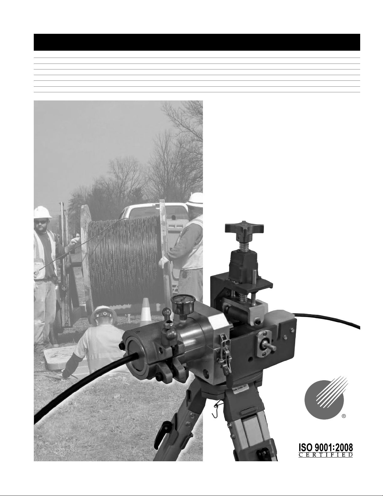
USER'S GUIDE & SAFETY MANUAL
Mini-Blower/Pusher
CONDUX
Page 2
Important Safety Notice
Read and understand all procedures and safety instructions before using the Mini-Blower/Pusher.
Observe all safety information on this page and note specific safety requirements as explained by
procedures in this manual. Failure to follow these instructions could result in serious personal injury
or death.
ADVERTENCIA:
Favor de leer y comprender todas las instucciones de operación y seguridad antes de usar la máquina. Si
Ud. no comprende las instrucciones favor de consultarle a su jefe.
READ MANUAL
FIRST
Save this user’s guide for future reference.
COMMUNICATIONS WITH THE MANUFACTURER
For any information related to the machine (use, maintenance, spare parts) always state Model, Serial
Number, Manufacturing Year and Order. This data can be found in the machine identification table.
Manufacturer:
Condux International Inc.
145 Kingswood Drive
Mankato, MN 56002-0247
1-507-387-6576
Fax 1-507-387-1442
Internet: http://www.condux.com
E-mail: cndxinfo@condux.com
If you have questions on:
2
SAFETY - OPERATIONS - APPLICATIONS
CALL 1-800-533-2077
CONDUX
Page 3

Table of Contents
General Information .................................................4
1
Technical Specifications .............................................5
2
A. Air Compressor Requirements .................................. 5
B. Operational Capacities ........................................ 5
C. Physical Specifications ........................................ 5
Safe Operating Procedures ........................................... 6
3
A. Work Area Safety ............................................6
B. Pneumatic Devices ........................................... 6
Unpacking the Blower ...............................................6
4
A. Blower Components .......................................... 6
Set Up the Blower/Pusher ............................................ 7
5
A. Mounting the Blower/Pusher to Tripod ............................7
B. Configure the Blower/Pusher ...................................7
Blower/Pusher Operating Instructions ................................... 9
6
A. Final Connections. . . . . . . . . . . . . . . . . . . . . . . . . . . . . . . . . . . . . . . . . . . . 9
B. Operations ................................................10
Appendixes ...................................................... 12
7
A. Charts .................................................... 12
B. Duct Rod Pusher ...........................................14
C. Blower/Pusher Assembly ..................................... 16
D. Mini-Blower Assembly ....................................... 17
E. Clamp Adjustment Screw ..................................... 18
F. Mount Clamp Assembly ...................................... 19
G. Clamp Roller Assembly ......................................19
3
Page 4

1.
General Information
The operating instructions contain a full description of the Condux Mini-Blower/
Pusher, which has been designed for the purpose of feeding fiber optic cable through
round conduits of uniform cross section. The conduit must previously have been
installed underground or overhead to receive the fiber optic cable and must be of
sufficient length on exit to be received by the machine. The conduit must be made of
material with sufficient compression strength for it to be adequately sealed in the exit
of a machine.
The fiber optic cable is continuously pushed into the conduit by a roller drive powered
by a cordless, corded or pneumatic drill. The exit of the machine consists of an air
box that is made in two halves that clamp together. The air box contains special
removable seals on entry and exit, which clamp around either the end of the conduit
or the fiber optic cable to be fed into the conduit. The seals can be changed to
accommodate different conduit and fiber optic cable sizes. The conduit is clamped
between a pair of seals at the entrance to the air block.
A clamp located in front of the entrance to the air block holds the conduit
mechanically to prevent it from moving axially. The fiber optic cable enters through
two seals located in an aluminum nozzle that splits in half. The aluminum nozzle is
located in the entrance to the air box and is shaped to ensure an airtight seal around
the fiber optic cable. When the two halves of the air box are closed, air pressure is
admitted into the space between the seals on entry and exit.
The use of the Mini-Blower/Pusher for operations different from those discussed in
this manual are considered extremely dangerous and thus forbidden. The non-respect
for the prescribed restraints of the machine causes a situation of improper use and
relieves the manufacturer from any responsibility, civil or penal. The manufacturer’s
responsibility declines even when one of the following happens:
a. The consequences caused by tampering and/or modifications carried out without
the manufacturer’s written acceptance.
b. The use of imitative spare parts.
c. Bad maintenance.
d. Use with disconnected safety devices.
e. The connection to machine and/or parts not produced and not directly authorized
by the manufacturer in a written acceptance.
The Condux Mini-Blower/Pusher is a unique device for inserting fiber optic cable
directly into conduit. The unit is comprised of an air block and a roller drive that,
when combined with an air compressor and a drill drive force, will propel fiber optic
cable measuring from .23" to .50" (5.8 mm to 12.7 mm) into an unobstructed,
unoccupied, airtight conduit.
GENERAL MACHINE USE
a. Only qualified operators should use the machine. The operator should only be the
person who received qualified training from the product owning company or trained
by the manufacturer.
b. Machine must only be used for the work it was designed for.
c. Machine is not to be used with unauthorized personnel on the job site.
d. Should there be any doubt concerning use, functioning, maintenance or
anything else, please contact the factory or factory representative.
4
Page 5

OPERATOR QUALIFICATIONS
a. Operator must know the required safety directives to run the machine that are
pertinent to the country where it is being used.
b. Operator in charge of the machine and installation project must be appropriately
dressed, avoiding large clothes, hanging jewelry or whatever might become
entangled in the moving parts.
c. Operator must also wear the necessary protective equipment such as gloves,
boots, helmet, etc.
d. Operator must carefully follow all advisements contained in the instruction
manual or on the machine.
e. Operator must have work area kept clean of obstacles that might inhibit a safe
working area.
MAINTENANCE QUALIFICATION
a. All of the machine maintenance must be carried out with the machine on a level
surface and not attached to any form of power source: electrical, or pneumatic.
b. Authorized and trained personnel must do all maintenance operations. Trained
personnel are defined as people who have received qualified training from the
using company or from the manufacturer.
Technical Information
A. AIR COMPRESSOR REQUIREMENTS
Pneumatic Pressure: 40 PSI (12 BAR) MAXIMUM IN MICRODUCT
100 PSI in Traditional Duct
Required Flow Capacity: 185 SCFM (11 M3/MIN) MAXIMUM
Conduit Size: 10 MM – 1.50" OD
Air hose fittings need to be compatible with Dixon “Air King” universal couplings
B. OPERATIONAL CAPACITIES
• Cable sizes: .23" TO .50" (5.8 MM TO 12.7 MM)
• Conduit sizes:10-18MM, ½", ¾",1", 1-1/4" TRUE, 1-1/4", 1-½" SDR 11 & 13.5 AND
METRIC O.D. CONDUIT; 25 MM, 32 MM, 36 MM, 37 MM,
C. PHYSICAL SPECIFICATIONS (DOES NOT INCLUDE TRIPOD OR JOB BOX)
• Height 12"
• Length 14"
• Width 8"
• Weight 17 lbs
2.
5
Page 6

3.
Safe Operating Practices
Read and understand all procedures and safety instructions before using the Condux
Mini-Blower/Pusher. Observe all safety information on this page and note specific
safety requirements as explained by procedures called out in this manual. Failure to
follow these instructions could result in serious personal injury, property damage
or death.
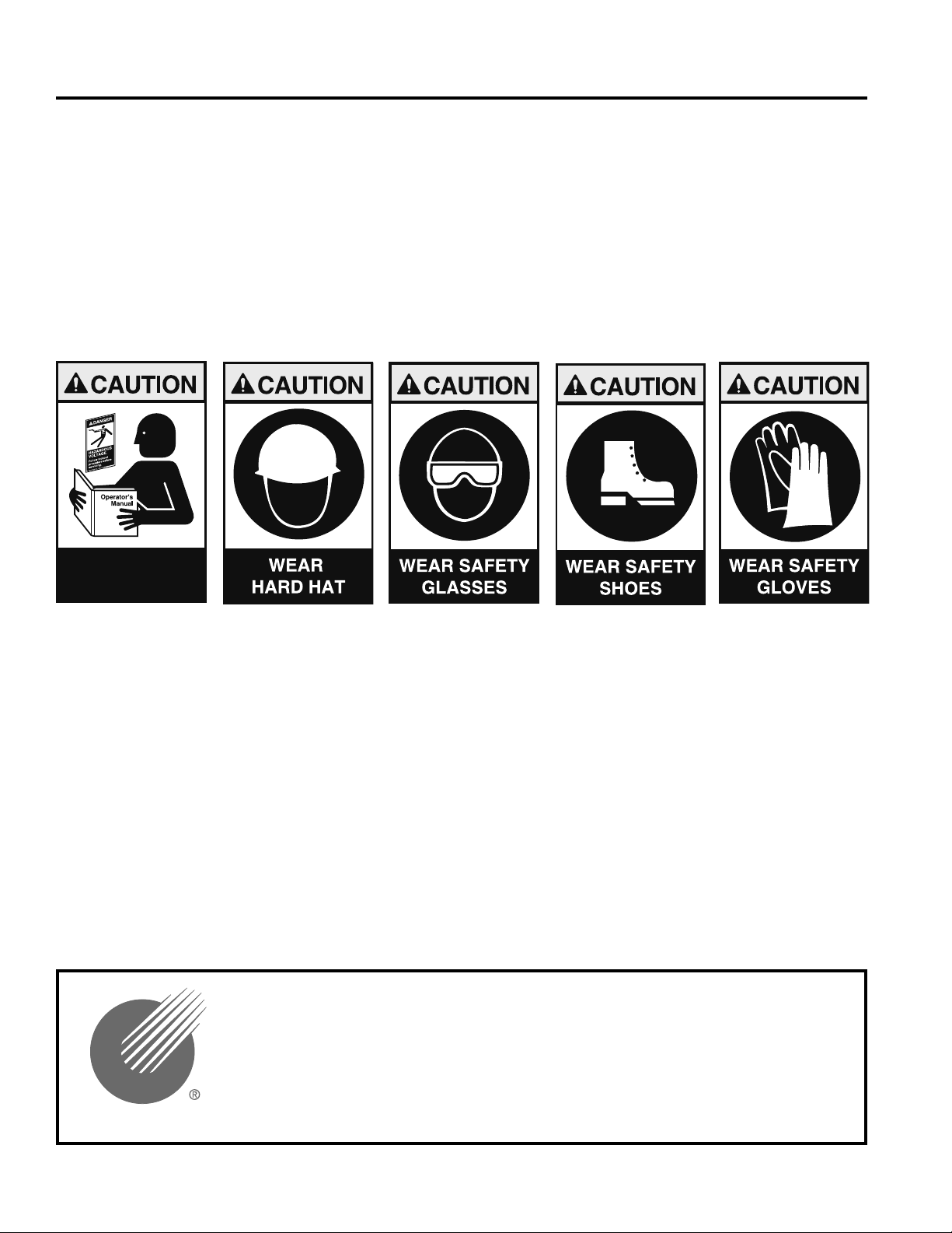
A. WORK AREA SAFETY
1. Wear personal protective equipment: hard hat, safety glasses, safety shoes, and
leather work gloves.
2. The safe operation of this equipment requires that the operators be on stable
footing.
3. Stay clear of cables or lines under tension.
4. Stay clear of pressurized line and conduit.
5. Stay out of manhole while blower is in use.
6. Use the blower only for its intended purpose. Do not use the tractor drive
without the air block to push or pull cable.
7. Do not place cable reel too close to unit. Place the reel far enough away from the
unit to ensure proper control.
8. Do not tamper with relief valves or pressure reducing valves.
9. Place cable grip on end of conduit to catch cable carrier and cable.
10. Keep hands away from tractor drive while blower is in operation.
4.
B. PNEUMATIC DEVICES
The Condux Mini-Blower/Pusher is a pneumatic device, using pressurized air to
project cable at high velocities. Please observe the following precautions when
operating the blower:
1. Forced air creates flying debris. Always wear personal protective equipment.
Severe personal injury could result.
2. Ensure no personnel are in the destination access vault during the blowing
operation. Severe personal injury could result.
Unpacking the Blower
A. BLOWER COMPONENTS
Each Mini-Blower/Pusher Package contains the following items.
COMMON PARTS PACKAGE:
Part No Description
02290168 Hex key set metric and standard
08780126 Seal replacement kit
08780223 Venturi Plug
08780424 Capscrew set (m04-0.7 x 16)
6
Page 7

Actual parts:
08081315 – blower assy
08081301 – pusher assy
08764110 – 12 mm duct pack
08764150 – 12.7 mm duct pack
08780302 – .23-.34 cable pack
08780304 – .35-.48 cable pack
NOTE: If any parts are missing: please contact your Condux representative or
call Condux International at 1-800-533-2077 (USA or CANADA), or
1-507-387-6576.
Set Up the Blower/Pusher
A. MOUNTING THE BLOWER/PUSHER TO TRIPOD (OPTIONAL)
NOTE: The Mini-Blower/Pusher can be operated without optional surveyor’s
style tripod. If using the unit without the tripod, move to step B.
1. Loosen and remove tripod mounting nut. (See figure 1)
2. Place Mini-Blower Drive assembly on tripod so that the mounting bolt extends
through the receiving in the base of the unit. Orient assembly as necessary.
3. Secure drive assembly to tripod by replacing and tightening the mounting nut.
(See figure 2)
5.
Figure 1. Mount Unit on Tripod
B. CONFIGURE THE BLOWER/PUSHER
1. Attach the blower assembly into the drive assembly. Match up the ridge on the
blower assembly with the corresponding groove on the mounting block portion of
the drive assembly.
Figure 2. Mount Pusher Base
on Tripod
7
Page 8

2. Once in place, secure the Blower Assembly to Drive Assembly using
(2) #10-24 x 1 1/2" Capscrews. (See figure 3)
3. Select and install the appropriate sized Duct Clamp and Duct Seal to the Blower
Assembly using (1) M04-0.7 x 16mm Capscrew for each. (See figure 4)
Figure 3. Mount Blower
Figure 4. Select & Install
Duct Packs
4. Select and install the appropriate sized Venturi to the Blower Assembly using (1)
M04-0.7 x 16mm Capscrew. (See figure 5)
5. Install the duct. (See figure 6)
Figure 5. Select and Install
Figure 6. Install Duct
Bottom Venturi
8
Page 9

6. Load cable through drive assembly. Select and install the appropriate size cable
seals for the specific project. (See figure 7)
7. Install top venturi. (See figure 8)
Figure 7. Select & Install Seals
Figure 8. Install Top Venturi
Blower/Pusher Operating
Instructions
A. FINAL CONNECTIONS
1. Secure the blower assembly by closing the hinged top and tightening the blower
clamp. (See figure 9)
2. Secure drive assembly by closing and locking the back clamp with locking clip.
(See figure 10)
6.
Figure 9. Tighten Blower Clamp
Figure 10. Install Back Clamp
9
Page 10

3. Adjust down pressure on cable by tightening the spring tensioned down pressure
adjustment to ensure positive contact with drive roller. (See figure 11)
4. Connect the air hose to the blower utilizing the universal claw type connector.
(See figure 12) Connect hose to air compressor follow specific manufacturer’s
instructions.
Figure 11. Adjust Pusher
Figure 12. Connect Air
Down Pressure
!WARNING: Forced air creates flying debris. Always wear personal protective
equipment. Severe personal injury could result.
!WARNING: Ensure no personnel are in the destination access vault during the
blowing operation. Severe personal injury could result.
B. OPERATIONS
1. Select the drive system and connect utilizing
the drive stem. (See figure 13)
Important: Make sure drive system is
oriented to turn the drive roller in the
proper direction.
Note: It is not recommended to run corded
or cordless drills in reverse for extend
periods of time.
10
Figure 13. Select Drive
Page 11

2. Open air control valve to engage air pressure. (See figure 14)
Important: Optimum air pressure not to exceed 40 PSI in microduct.
3. Engage drive system. Install fiber optic cable. (See figure 15)
Figure 14. Engage Air
Figure 15. Engage Drive
11
Page 12

A.
APPENDIX
4
Blower/Pusher Charts
MICRO DUCT PACKS
Duct Size OD
(MM)
10 08764140 08764142 08764143 5-9 mm 08913547
12 08764110 08764112 08764113 10-12 mm 08913545
12.7 08764150 08764151 08764153 10-12 mm 08913545
14 08764120 08764122 08764123 10-12 mm 08913545
16 08764130 08764132 08764133 10-12 mm 08913545
18 08781110 08781106 08781101 13-15 mm 08913538
Part
Number
Duct
Clamp
Duct
Seal
MINI-BLOWER/PUSHER CABLE PACKS
Pack Cable OD P/N Cable OD P/N Cable OD P/N
1
2
3
4 (10-12.7)
CABLE PACK VENTURI CABLE SEAL
0.23-0.34
(5.8-8.8)
0.35-0.48
(8.9-12.2)
0.49-0.60
(12.3-15.2)
08780802
Pack #1
08780804
Pack #2
08780806
Pack #3
08780755
Pack #4
0.23-0.34
(5.8-8.8)
0.35-0.48
(8.9-12.2)
0.49-0.60
(12.3-15.2)
08780803
08780805
08780807
Nylatron Venturi for Flat Fiber Optic Cables
INNERDUCT EYE
ID
Range
0.23-0.28
(5.8-7.2)
0.29-0.34
(7.3-8.8)
0.35-0.42
(8.9-10.7)
0.43-0.48
(10.8-12.2)
0.49-0.55
(12.3-14.0)
0.56-0.60
(14.1-15.2)
Part
Number
08780406
08780407
08761424
08761425
08761426
08761427
12
Page 13

2
PACK
0.23-0.34 (5.8-8.8)
1
3
0.35-0.60 (8.9-15.2)
2
0.61-0.85 (15.3-21.6)
3
0.86-1.13 (21.7-28.7)
4
CABLE PACK VENTURI CABLE SEAL CABLE GRIP
Cable OD P/N Cable OD P/N Cable OD P/N Cable OD P/N
08780393 Pack #1
08780394 Pack #2
08780395 Pack #3
08780396 Pack #4
REPLACEMENT CABLE PACKS
0.23-0.34 (5.8-8.8)
0.35-0.48 (8.9-12.2)
0.49-0.60 (12.3-15.2)
0.61-0.73 (15.3-18.5)
0.74-0.85 (18.6-21.6)
0.86-0.97 (21.7-24.6)
0.98-1.13 (24.7-28.7)
08780281
08780282
08780283
08780284
08780285
08780286
08780446
REPLACEMENT DUCT PACKS
PACK
1
2
3
4
5
6
7
8
9
10
11
12
13
14
15
16
DUCT PACK DUCT CLAMP DUCT SEAL CARRIER FOAM CARRIER CABLE GRIP
Duct Size P/N Duct OD P/N Duct OD P/N Carrier P/N
1/2"
SDR 11-
13.5
3/4"
SDR 11-
13.5
1"
SDR
11/13.5
1.25"
SDR
11/13.5
1.5"
SDR
11/13.5
2"
SDR
11/13.5
25 mm
32 mm
36 mm
37 mm
1.25"
TRUE
40 mm
42 mm
44 mm
46 mm
50 mm
08780795
Pack #1
08780680
Pack #2
08780386
Pack #3
08780392
Pack #4
08780397
Pack #5
08780930
Pack #6
08780240
Pack #7
08780385
Pack #8
08780387
Pack #9
08780388
Pack #10
08780389
Pack #11
08780390
Pack #12
08780391
Pack #13
08780545
Pack #14
08780460
Pack #15
08780575
Pack #16
0.84
(21.30)
1.050
(26.6)
1.315
(33.4)
1.660
(42.2)
1.900
(48.3)
0.984
(25.0)
1.260
(32.0)
1.417
(36.0)
1.457
(37.0)
1.500
(38.1)
1.575
(40.0)
1.653
(42.0)
1.732
(44.0)
1.811
(46.0)
1.969
(50.0)
08780791
08780682
08780369
08780375
08780404
—— —— —— ——
08780099
08780368
08780370
08780371
08780372
08780373
08780374
08780546
08780466
08780435
0.84
(21.30)
1.050
(26.6)
1.315
(33.4)
1.660
(42.2)
1.900
(48.3)
0.984
(25.0)
1.260
(32.0)
1.417
(36.0)
1.457
(37.0)
1.500
(38.1)
1.575
(40.0)
1.653
(42.0)
1.732
(44.0)
1.811
(46.0)
1.969
(50.0)
08780786
08780685 0.75 (19.0) 08780690 0.75 (19.0) 08078300
08780307
08780051
08780398
08780134
08780306
08780308
08780309
08780333
08780334
08780335
08780547
08780461
08780431
0.23-0.28 (5.8-7.2) 08780406
0.29-0.34 (7.3-8.8) 08780407
0.35-0.42 (8.9-10.7) 08761424
0.43-0.48 (10.8-12.2) 08761425
0.49-0.55 (12.3-14.0) 08761426
0.56-0.60 (14.1-15.2) 08761427
0.61-0.67 (15.3-17.0) 08761428
0.68-0.73 (17.1-18.5) 08761429
0.74-0.79 (18.6-20.1) 08761430
0.80-0.85 (20.2-21.6) 08761431
0.86-0.92 (21.7-23.4) 08761432
0.93-0.97 (23.5-24.6) 08761433
0.98-1.04 (24.7-26.4) 08761434
1.05-1.13 (26.5-28.7) 08761435
Carrier
0.688
(17.50)
1.121
(28.5)
1.414
(35.9)
1.618
(41.1)
2.023
(51.4)
0.787
(20.0)
1.063
(27.0)
1.181
(30.0)
1.220
(31.0)
1.220
(31.0)
1.250
(31.7)
1.299
(33.0)
1.378
(35.0)
1.496
(38.0)
1.299
(33.0)
1.606
(40.0)
08780793 0.75 (19.0) 08078300
08761250 1.25 (31.8) 08761439
08761255 1.50 (38.1) 08761440
08761260 1.75 (44.5) 08761441
08761265 2.00 (50.8) 08761442
08780230 1.25 (31.8) 08761439
08761560 1.25 (31.8) 08761439
08761643
08761555
08761555 1.25 (31.8) 08761439
08761670 1.50 (38.1) 08761440
08761579 1.50 (38.1) 08761440
08761660 1.50 (38.1) 08761440
08761786 1.50 (38.1) 08761440
08761579 1.50 (38.1) 08761440
08761579 2.00 (50.8) 08761442
1.25 (31.8) 08761439
OD
0.21-0.35 (5.3-8.9)
0.32-0.48 (8.1-12.2)
0.42-0.61 (10.7-15.5)
0.53-0.74 (13.5-18.8)
0.64-0.87 (16.3-22.1)
0.75-1.00 (19.1-25.4)
1.00-1.24 (25.4-31.5)
P/N Duct OD P/N
.75-.99
(19-25)
1.00-1.24
(25.4-31.5)
1.00-1.24
(25.4-31.5)
1.50-1.99
(38.1-50.5)
1.50-1.99
(38.1-50.5)
2.00-2.49
(50.8-63.2)
1.00-1.24
(25.4-31.5)
1.25-1.49
(31.8-37.8)
1.25-1.49
(31.8-37.8)
1.25-1.49
(31.8-37.8)
1.25-1.49
(31.8-37.8)
1.50-1.99
(38.1-50.5)
1.50-1.99
(38.1-50.5)
1.50-1.99
(38.1-50.5)
1.50-1.99
(38.1-50.5)
1.50-1.99
(38.1-50.5)
08643131
033-03-012
08643137
033-03-013
08643137
033-03-013
08643149
033-03-016
08643149
033-03-016
08643155
033-03-017
08643137
033-03-013
08643143
033-03-015
08643143
033-03-015
08643143
033-03-015
08643143
033-03-015
08643149
033-03-016
08643149
033-03-016
08643149
033-03-016
08643149
033-03-016
08643149
033-03-016
08643754
033-29-1194
08643755
033-29-1195
08643756
033-29-1196
08643757
033-29-1197
08643758
033-29-1198
08643759
033-29-1199
08643137
033-03-013
INNERDUCT
EYE
P/N and ID
Range
08761840
.78-.87 (20-22)
08761840
.71-.89 (18-22)
08761842
1.06-1.43
(27-37)
08761842
1.06-1.43
(27-37)
08761844
1.37-1.68
(35-43)
08761844
1.37-1.68
(35-43)
08761840
.71-.89 (18-22)
08761842
1.06-1.43
(27-37)
08761842
1.06-1.43
(27-37)
08761842
1.06-1.43
(27-37)
08761842
1.06-1.43
(27-37)
08761842
1.06-1.43
(27-37)
08761842
1.06-1.43
(27-37)
08761842
1.06-1.43
(27-37)
08761842
1.06-1.43
(27-37)
08761844
1.37-1.68
(35-43)
13
Page 14

B.
APPENDIX
Duct Rod Pusher
14
Page 15

DUCT ROD PUSHER (08081301)
ITEM PART NUMBER DESCRIPTION QTY
1 02021400 CAPSCREW, HEX HEAD 1/4-20 X 0.75LG GR5 CZ 2
2 02102001 FLATWASHER, 1/4 TYPE A NARROW CZ 7
3 02240800 CAPSCREW, BUTTON HEAD #10-24 X 0.50LG SS 4
4 02269675 CAPSCREW, BUTTON HEAD #08-32 X 0.38LG SS 16
5 02269678 SPRING,COMPRESSION 1.095OD x 0.105WD x 1.00LG 1
6 02269687 BEARING,BALL W/SEALS 15MM ID X 28MM OD 2
7 02287830 SETSCREW, HEX SOCKET #10-24 X 0.25LG W/NYL TIP 2
8 02288425 CAPSCREW,HEX HEAD 1/4-20 X 1.75LG GR5 CZ 2
9 02288443 SCREW,TAPPING #10 X 1.00LG TYPE AB HEX HEAD CZ 4
10 02290269 CLAMP,TOGGLE 360LB PULL ACTION 2
11 08081302 BLOCK,GUIDE-NYLON 1
12 08081305 ROLLER,CENTER DRIVE 1
13
14 08081308 BLOCK,LOWER CLAMP 1
15 08081309 BLOCK,UPPER CLAMP 1
16 08081310 SHAFT,DRIVE-CENTER ROLLER 2
17 08761033 SCREW,CLAMP ADJUSTMENT - ASSEMBLY 1
18 08761034 BODY,COUNTER-MACHINED 1
19 08761036 INSERT,CLAMP ROLLER ADJUSTMENT 1
20 08761045 HOUSING,BEARING-DRIVE SHAFT 2
21 08761510 MOUNT,CLAMP ROLLER 1
22 08761516 MOUNT,CLAMP ADJUSTMENT SCREW 1
23 12013700 NUT, LOCK NUT 1/4-20 GR5 - NYLOC 2
24 21032451 KEY,DRIVE SHAFT 3/16 SQ X 0.50LG 2
080
81319
SLEEVE,DRIVE ROLLER
1
15
Page 16

C.
APPENDIX
Blower/Pusher Assembly
16
BLOWER/PUSHER ASSEMBLY (08780800)
ITEM PART NUMBER DESCRIPTION QTY
1 02288338 CAPSCREW, #10-24 x 1.50LG COUNTERSUNK 2
2 08081301 DUCTROD PUSHER ASSEMBLY 1
3 08081315 MINI-BLOWER ASSEMBLY 1
Page 17

Mini-Blower Assembly
D.
APPENDIX
MINI-BLOWER ASSEMBLY (08081315)
ITEM PART NUMBER DESCRIPTION QTY
1 00263400 CORD,QUAD-RING 3.5MM CS X 3.75LG 2
2 02020000 FITTING,HYD 1/2IN MALE NIPPLE 1
3 02129700 COUPLING,UNIVERSAL 1/2IN MALE 1
4 02272600 FITTING,HYD ELBOW 1/2IN (M) O-RING/ 1/2IN (M) JIC 1
5 02288582 GAUGE,PRESSURE 1 1/2IN DIA BACK MNT 0-200 PSI 1
6 02288665 NUT,HEX LOCK M06-1.00 NYLOC 1
7 02288694 NUT,HEX LOCK M08-1.25 NYLOC 1
8 02289293 BOLT,SWING M10-1.50 X 100MM LG 2
9 02289294 SCREW,SHOULDER M10 DIA X 40MM LG 1
10 02289295 SCREW,SHOULDER M08 DIA X 70MM LG 1
11 02289297 CAPSCREW,COUNTERSUNK M06-1.00 X 12MM LG SS 4
12 02289382 NUT,HEX LOCK M10-1.50 NYLOC THIN 1
13 08081316 ADAPTER,LOWER INSERT - MB 1
14 08081317 ADAPTER,UPPER INSERT - MB 1
15 08764001 COUPLING,BODY - HAND HELD BLOWER 2
16 08764006 HANDLE,SPEED-BALL - M10 THREADS 1
17 08780223 PLUG,VENTURI AIR 1
18 11274400 VALVE,BALL 1/2IN 1
17
Page 18

E.
APPENDIX
Clamp Adjustment Screw
18
CLAMP ADJUSTMENT SCREW
ITEM PART NUMBER DESCRIPTION QTY
1 02102001 FLATWASHER, 1/4 TYPE A NARROW CZ 1
2 02287600 FLATWASHER, 1/4 NYLON 2
3 02288555 CAPSCREW, BUTTON HEAD 1/4-28 X 0.75LG SS 4
4 08761033 SCREW,CLAMP ADJUSTMENT - ASSEMBLY 1
5 08761510 MOUNT,CLAMP ROLLER 1
Page 19

Mount Clamp Assembly
MOUNT CLAMP ASSY
ITEM PART NUMBER DESCRIPTION QTY
F.
APPENDIX
1 02102001 FLATWASHER, 1/4 TYPE A NARROW CZ 1
2 02290268 SCREW,SHOULDER 1/4 DIA X 3.25LG 1
3 08081311 ROLLER,CLAMP ASSEMBLY 1
4 08761510 MOUNT,CLAMP ROLLER 1
Clamp Roller Assembly
G.
APPENDIX
CLAMP ROLLER ASSEMBLY (08081311)
ITEM PART NUMBER DESCRIPTION QTY
1 02290379 RING,RETAINING 5/8 EXT (1000 SERIES) 2
2 08081313 SLEEVE,CLAMP ROLLER-PU 1
19
Page 20

Available Options
HEAVY DUTY TRIPOD
The Mini-Blower/Pusher mounts easily to the surveyor style
tripod, which adds stability and versatility to fiber optic cable
installations.
PNEUMATIC DRILL DRIVE “Y” CONNECTOR
A "Y" Connector air hose option allows for the use of a
pneumatic drill drive configuration. Unit also comes with
variable pressure control.
Heavy Duty Tripod
Part # 08780850
"Y" Connector Air Hose
Part # 08780855
MINI-BLOWER/PUSHER JOB BOX
The Mini-Blower/Pusher is easy to handle and
transport. The blower and all accessories including
cable and conduit packs and seal kits conveniently
fit into the lightweight job box.
Job Box with Kit
Part # 08780801
Condux International, Inc.
P.O. Box 247 • 145 Kingswood Drive, Mankato, MN 56002-0247 USA
1-507-387-6576 • 1-800-533-2077 • FAX 1-507-387-1442
www.condux.com • e-mail: cndxinfo@condux.com
© Copyright 2011, Condux International, Inc.
Printed
Literature Part Number: 08780899
Revision Number: 1.1
in USA
 Loading...