

Page 1
P M
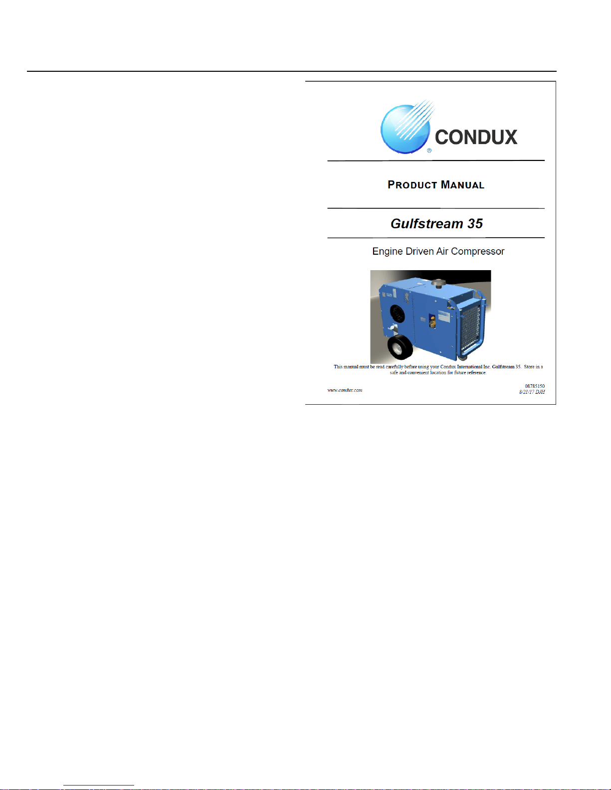
Gulfstream 35
Engine Driven Air Compressor
This manual must be read carefully before using your Condux International Inc. Gulfstream 35. Store in a
www.condux.com
safe and convenient location for future reference.
08785150
8/21/17 DJH
Page 2

- 2 -
08785150
Page 3

Contents
Welcome...............................................4
General Information.........................................4
Safety....................................................5
General Safety Overview.................................5
Safety Precautions...........................................6
Specifications......................................8
Specification Sheet..........................................8
Installation & Operation......................9
Lifting................................................................9
Mounting the Compressor..............................10
Pre-Start-up Inspection Checks.....................11
Check All Fluid Levels....................................11
Machine Documentation................................11
Operating Procedure......................................11
Shutdown Procedure.....................................12
Operating Conditions.....................................12
Maintenance.......................................13
Lifetime Warranty Information........................13
Recommended Spare Parts List....................13
How To Order Parts.......................................13
Parts List........................................................14
Maintenance Chart.........................................15
Compressor Oil..............................................16
Air / Oil Coalescer .........................................16
Compressor Oil Fill, Level, and Drain............17
Belt Tensioning Procedure.............................17
Changing the Air Intake Filter........................17
Belt Replacement Procedure.........................17
Troubleshooting................................18
Machine Will Not Start....................................18
Unplanned Shutdown.....................................18
Sump Pressure Does Not Blow Down...........18
Engine Overheating.......................................18
Improper Discharge Pressure........................19
Coalescer Plugging........................................19
Oil Consumption.............................................19
High Compressor Discharge Temperature....19
Contacting Condux International, Inc...20
- 3 -
08785150
Page 4
Welcome
General Information
Thank you for choosing the Condux International,
Inc. Gulfstream 35 Engine Driven Air Compressor.
Before operating, carefully read this manual and
become well acquainted with your new machine.
Doing this will increase your safety and maximize
the life of the machine.
While this manual is written to be as accurate as
possible, Condux International, Inc. strives to
continually improve the efficiency and performance
of its machines. As a result, sometimes there may be
slight differences between a given version of the
manual and the machine.
- 4 -
08785150
Page 5

General Safety Overview
Safety
IMPORTANT: READ BEFORE OPERATING
EQUIPMENT
Remember, safety is basically common sense. While
there are standard safety rules, each situation has its
own peculiarities that cannot be covered by rules.
Therefore with your experience and common sense,
you are in a position to ensure the safety of yourself
and those around you. Lack of attention to safety can
result in: accidents, personal injury, reduction in
efficiency, and worst of all - Loss of Life. Watch for
safety hazards and correct them promptly.
Understanding the proper operation of this equipment
is critical to its safe operation. The owner, lessor, or
operator of this equipment is hereby notified and
forewarned that any failure to observe the safety and
operating guidelines may result in injury and/or
damage. Condux International, Inc. expressly
disclaims responsibility or liability for an injury or
damage caused by failure to observe the specified
precautions or by failure to exercise the ordinary
caution and due care required while operating or
handling this equipment, even though not expressly
specified.
In addition to following these safety guidelines, the
operator should follow any company specific
guidelines and procedures. Consult your immediate
supervisor for specific company safety guidelines
and/or procedures.
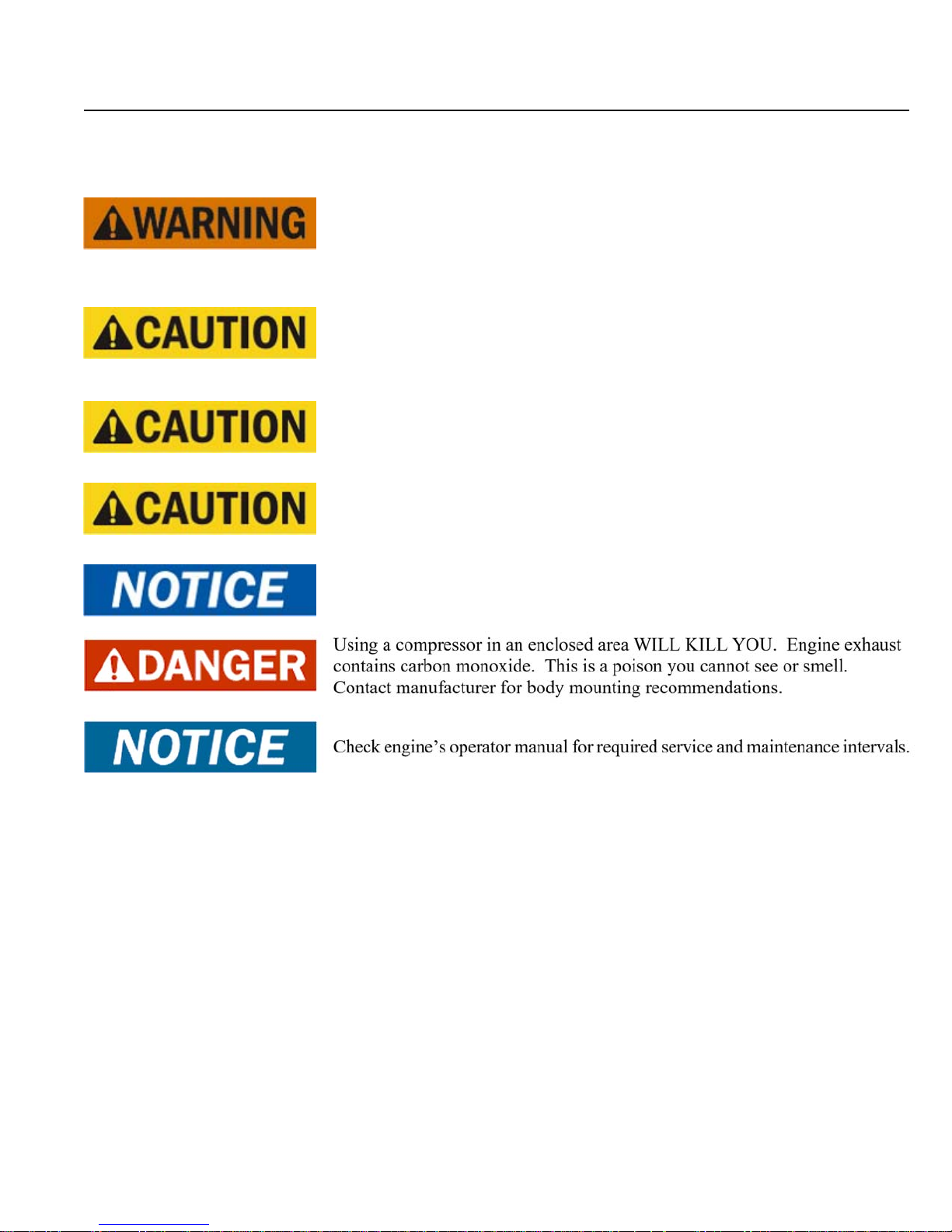
The following safety symbols are used throughout the
manual to draw attention to important information.
If the information is not carefully read and the
instructions are not followed, severe injury, death,
Indicate[s] an imminently hazardous situation, which, if not avoided, will result
in death or serious injury.
Indicate[s] a potentially hazardous situation, which, if not avoided, could result
in death or serious injury.
Indicate[s] a potentially hazardous situation, which, if not avoided, could result
in minor or moderate injury.
Indicate[s] a potentially unsafe situation or practice, which, if not avoided, can
result in property and/or equipment damage only
- 5 -
08785150
Page 6

Safety
Safety Precautions
The following safety precautions are a general guide to safe operation of the equipment.
- 6 -
08785150
Page 7
Safety Precautions (continued)
Read and understand the operations manual and all other safety instructions
before using this equipment. Failure to follow operating instructions and/or
failure to follow maintenance procedures and intervals could result in personal
injury, death, and/or damage to equipment and property.
Mount the compressor in a stable location capable of supporting the weight of
the machine. Slight vibration may occur during operation and the machine
may move if not securely mounted.
When using tools, maintain secure footing at all times. Do not overreach or
awkwardly use air tools.
Never place machine on a grade more than 15 degrees.
Safety
Use only Condux International, Inc. approved replacement parts or equivalent.
- 7 -
08785150
Page 8

Specification Sheet
Specifications
COMPRESSOR SPECIFICATIONS
Model Gulfstream 35
Type
Delivery 35 CFM @ 215 PSI
Operating Pressure
Range
Ambient Operating
Temperature Range
Oil Capacity 2 gallons
Air Service Connection 3/4” NPT
* CONTACT CONDUX INTERNATIONAL, INC. FOR 5000+ FEET ALTITUDE OPTIONS.
Engine Driven Air
Compressor
80 - 215 PSIG
0° - 100°F
ENGINE SPECIFICATIONS
Model CH730
Type
Rated Power 24.8 HP 3600
Displacement 44 cubic inches
Bore and Stroke 3.27” X 2.64”
Oil Capacity 1.7 quarts
Battery 12V - 425 CCA @ 32º F
Fuel Tank
Capacity
Altitude Range 0-5000 feet *
Kohler 4-Cycle V-Twin OHV
Air Cooled Gasoline
Output RPM
5 gallons
GENERAL SPECIFICATIONS
Overall Dimensions 45” L X 20” W X 34.44” H
Weight 575 lbs
SPECIFICATIONS SUBJECT TO CHANGE WITHOUT PRIOR NOTICE
- 8 -
08785150
Page 9

Installation & Operation
Lifting
Condux International Inc. offers a lifting bail option
for routine lifting, loading onto trucks, etc.
Compressors to be air lifted by helicopter must not
be supported by the lifting provision, but by slings
with appropriate spreader bars. Lift only in full
compliance with OSHA standards 29 CFR 1910
subpart N.
Inspect lifting provision for cracked welds and for
cracked, bent, corroded or otherwise degraded
members prior to lifting.
Make sure entire lifting, rigging and supporting
structure has been inspected, is in good condition and
had a rated capacity of at least the net weight of the
compressor plus and additional 10% allowance for
the weight of snow, ice, mud or stored tools and
equipment. If you are unsure of the weight, then
weigh the compressor before lifting.
● Make sure lifting hook has a functional safety
latch, or equivalent, and is fully engaged once it
has been lifted clear of the ground.
● Do not attempt to lift in high winds.
● Keep all personnel out from under and away from
the compressor when suspended.
● Lift compressor slowly and smoothly, without
jerking.
● Lift compressor no higher than necessary.
● Keep lift operators in constant attendance
whenever compressor is suspended.
● Set compressor down only on level surfaces
capable of supporting at least its net weight plus
an additional
● 10% allowance for the weight of snow, ice, mud
or stored tools and equipment.
- 9 -
08785150
Page 10

Installation & Operation
Mounting the Compressor
When mounting the compressor, care should be taken
to ensure that its location does not impede the
operation of other components on the vehicle. For
example, if your vehicle is equipped with a crane, you
must make sure the compressor will not interfere with
the swing of the crane. In addition, the compressor
should be installed in an area that permits cool
ambient air to enter the air filter and the hot air to
exhaust without recirculating into the machine. A
minimum of 10” of clearance is needed for the hot
discharge air from the cooler. A minimum of 10” of
clearance is required from the rear of the compressor
to allow for proper air intake. Cool ambient air is
drawn in from the rear of the machine. The unit
should be secured to the vehicle with four 3/8” grade
8 bolts, flat washers, and loc washers. Ensure that
you have a sub structure that will support the weight
of the compressor. Be sure to follow all National
Vehicle Safety Standards.
- 10 -
08785150
Page 11

Installation & Operation
Pre-Start-up Inspection Checks
This inspection should be done prior to the
compressor test.
I. Check all assemblies, clamps, fittings, hose
connections, nuts, and bolts to ensure they are
properly tied and secured to the vehicle. This
is a very critical area of inspection. The
vehicle should not be moved until this
inspection has been completed.
II. Remove all tools, rags, and installation
equipment from the area.
III. Check compressor oil level and check all
valves to ensure they are in correct operating
position.
IV. Vacuum all areas that have metal or plastic
shavings. Wipe all fingerprints off unit and
vehicle.
Machine Documentation
Record all serial numbers for this installation.
A. Condux International Inc. Serial Number
_________________________________________
B. Engine Serial Number
_________________________________________
C. Compressor Serial Number
_________________________________________
D. Note any special applications relating to
specific installations
_________________________________________
_________________________________________
_________________________________________
Check All Fluid Levels
Position the unit on a level surface so that proper
amount of fluids can be added.
I. 5 gallons of gasoline
II. Engine oil level may have to be topped off
after test.
III. Check compressor oil level
A. Add oil if needed.
B. Additional oil may need to be added after
test.
C. Top off oil level to half the sightglass
when finished with the test.
Operating Procedure
I. Read this manual carefully before proceeding.
II. Verify the service valve is closed.
III. Pull the choke cable and start engine. If the
engine is warm or the ambient temperature is
high, pull the choke knob halfway, or keep it
fully open.
IV. Allow 3-5 minutes for engine to warm up
V. Open service valve
- 11 -
08785150
Page 12

Installation & Operation
Shutdown Procedure
I. Close service valve
II. Allow 3-5 minutes for engine to run at low
speed
III. Turn switch key off
Operating Conditions
The following conditions should exist for maximum
performance of the compressor:
● The machine should be as close to level as
possible when operating.
● Ambient temperature for operation should be
below 100°F (38°C). The machine may
experience high temperature shutdown above
this level.
- 12 -
08785150
Page 13

Maintenance
Recommended Spare Parts List
PART
DESCRIPTION
NUMBER
Compressor Air Filter
02291791
Element
02291800 3VX425 Belt
50-Hour Maintenance Kit
02291801
(Two 5 liter containers of
oil and oil filter)
1-Year or 500-Hour
Maintenance Kit (Two 5
02291802
Liter Containers of Oil, Oil
Filter, Oil Coalescer, Air
Filter)
How To Order Parts
Phone: (800) 533-2077
Lifetime Warranty Information
In order to maintain the lifetime warranty status on
your Gulfstream 35 the required maintenance
intervals listed on the following page must be obeyed.
Fax: (507)-387-1442
Email: orders@condux.com
Website: www.condux.com
- 13 -
08785150
Page 14

Maintenance
Parts List
- 14 -
08785150
Page 15

Maintenance
Maintenance Chart
The MAINTENANCE CHART lists serviceable items on this compressor package. The items are listed
according to their frequency of maintenance.
INTERVAL REQUIRED MAINTENANCE
1. Check separator tank oil level.
EVERY 10 HOURS OR
DAILY
EVERY 50 HOURS OR
WEEKLY
2. Check for fuel, oil, and air leaks.
3. Check compressor air filter maintenance indicator.
4. Check battery hold down for security.
1. Drain liquid from separator tank. More frequent draining may be
required under high humidity conditions.
2. Inspect lifting frame
3. Inspect Belts
4. After first 50 hours install Condux P/N 02291801 50-Hour
Maintenance Kit. Steps include changing oil and oil filter element.
Then follow yearly maintenance schedule.
1. Clean battery terminals
2. Check battery hold-down and cables for wear
3. Check compressor air filter connections, fittings, and clamps.
4. Check all door gaskets, hinges, and latches.
EVERY 500 HOURS
OR 1 YEAR
5. Clean cooler fins on all coolers.
6. Check separator tank pressure relief valve.
7. Install Condux P/N 02291802 1-Year or 500-Hour Maintenance
Kit. Steps include changing oil, oil filter element, air/oil coalescing
element, and air filter element. After this, regular intervals should
be used for changing oil and air filters.
- 15 -
08785150
Page 16

Compressor Oil
Maintenance
It is important that the compressor oil be of a
recommended type, and inspected and replaced as
stated in this manual.
The combination of a coalescer element loaded with
dirt and oxidized oil products together with increased
air velocity as a result of this clogged condition may
produce a critical point while the machine is in
operation where ignition can take place and could
cause a fire in the separator tank.
The following are general characteristics for a
rotary screw lubricant. Due to the impossibility of
establishing limits on all physical and chemical
properties of lubricants which can affect their
performance in the compressor over a broad range
of environmental influences, the responsibility for
recommending and consistently furnishing a
suitable heavy duty lubricant must rest with the
individual supplier if they choose not to use the
recommended ShieldWorks rotary screw lubricant.
The lubricant supplier’s recommendation must,
therefore, be based upon not only the following
general characteristics, but also upon his or her own
knowledge of the suitability of the recommended
lubricant in helical screw type air compressors
operating in the particular environment involved.
Recommended Compressor Lubricant:
ShieldWorks
The Lifetime Warranty is initiated with the factory
fill of the machine with ShieldWorks lubricant. To
maintain lifetime warranty status on the airend, the
lifetime warranty registration must be completed and
required maintenance schedules must be followed.
Due to environmental factors, the useful life of all
“extended life” lubricants may be shorter than quoted
by the lubricant supplier. Condux International, Inc.
encourages the user to closely monitor the lubricant
condition and to participate in an oil analysis program
with the supplier.
No lubricant, however good and/or expensive, can
replace proper maintenance and attention. Select and
use it wisely.
Air / Oil Coalescer
This is a single piece unit that requires replacement
when it fails to remove the oil from the discharge air.
To replace element, P/N 02291790, proceed as follows:
1. Shutdown compressor and wait for complete
blow down (zero pressure).
2. Turn element counterclockwise for removal.
1. Specifications
1. Flash point 496°F minimum.
2. Pour point -40°F.
3. Contains rust and corrosion inhibitors.
4. Contains foam suppressors.
5. Contains oxidation stabilizer.
DexTron 3 or equivalent may be used, but not
DexTron 6. AW32 Hydraulic Oil can be used to
“top off” the system in critical situations.
- 16 -
3. Install new rubber seal in head and supply a
film of fluid directly on the seal.
4. Rotate element clockwise by hand until
element contact seal (as viewed from top).
5. Rotate element at edge of can one more turn
clockwise with band wrench.
6. Run system and check for leaks.
08785150
Page 17

Maintenance
Compressor Oil Fill, Level, and
Drain
Before adding or changing compressor oil, make sure
that the compressor is completely relieved of pressure.
The drain is located inside the service door on the
bottom of the sump tank. To drain the oil, remove the
drain plug in the bottom of the tank.
Oil is added at the fill cap on the side of the machine.
The proper oil level is in the middle of the oil
sightglass when the unit is shut down and has had
time to settle. The machine must be level when
checking the oil. The fill neck is designed to prevent
overfilling; however, care must still be taken to ensure
the proper oil level. DO NOT OVERFILL. The oil
capacity is given in “Compressor Specifications”.
Changing the Air Intake Filter
The air intake filter is a heavy-duty dry type high
efficiency filter designed to protect the compressor
from dust and foreign objects.
Frequency of maintenance of the filter depends on
dust conditions at the operating site. The filter
element must be serviced when clogged. A clogged
air filter element will reduce compressor performance
and cause premature wear of components.
Do not substitute element. Use only a Condux
International, Inc. approved replacement element.
This element is rated at 350 PSI working pressure.
Use of any non-approved element may be hazardous
and could impair the performance and reliability of
the compressor, possibly voiding the warranty and/or
resulting in damage to property and serious bodily
harm.
Belt Tensioning Procedure
First, be sure the unit is off and the key is removed.
Then use a 3/4” socket to turn the compressor slide
plate adjustment bolt clockwise to tighten the
compressor belts. Proper belt tensioning is 1/4”
deflection @ 3.3 to 5 lbs of force per belt.
Belt Replacement Procedure
First be sure that the unit is off and they key is
removed. Then use a 3/4” socket to turn the
compressor slide plate adjustment bolt counter
clockwise to loosen the compressor belts. Only loosen
enough to remove belts. Next, remove the old belts
and install the new ones. Use a 3/4” socket to turn the
compressor slide plate adjustment bolt clockwise to
tighten the compressor belts. Proper belt tensioning
is 1/4” deflection @ 3.3 to 5 lbs of force per belt. Use
a belt tensiometer to properly tension the belts.
- 17 -
08785150
Page 18

Troubleshooting
Unplanned Shutdown
If the machine shuts down unexpectedly, check the
following:
I. Check to determine if compressor oil is at
proper level
II. Check oil cooler for dirt, slush, ice on the fins,
or any other obstructions to cooling airflow
III. Make a thorough external check for any cause
of shutdown such as broken hoses, oil lines,
wires, etc.
IV. Check compressor high discharge temperature
switch; it should normally be open. The
switch is located in piping on the bottom of
sump tank.
Machine Will Not Start
If the machine will not start, check the following:
I. Fuel level
II. Plugged fuel filter
III. Low battery voltage
IV. Loose battery cables
V. Plugged air filter
VI. Engine problems may have developed, refer
to your engine manual
VII. Defective engine oil pressure switch, check
continuity
VIII. Bad compressor high discharge temperature
switch. This switch is normally open. Check
for continuity across both terminals.
V. Check electric fan motor and wiring.
Sump Pressure Does Not Blow
Down
If after the compressor is shutdown, pressure does not
automatically blow down (this process should take
about 1 minute), check for:
I. Automatic blow down valve may be
inoperative.
II. Blockage in air line form blow down valve to
coalescer head.
III. Orifice at blow down clogged.
Engine Overheating
If the engine is overheating, check the following:
- 18 -
I. Check oil level. Add oil if required.
II. Air blockage into engine from blower side.
III. Air blockage from exhaust side of engine.
IV. Dirty oil in engine.
08785150
Page 19

Troubleshooting
Improper Discharge Pressure
If discharge pressure is too low, check the following:
I. Too much air demand. (Air tools required
more air than the compressor can produce, air
tools are free wheeling without resistance.)
II. Service valve is wide open to atmosphere.
III. Leaks in service line.
IV. Restricted compressor inlet air filter.
V. Faulty control system operation (i.e. regulator
is sending a signal to close the inlet valve at
all times).
VI. Low engine speed
VII. Worn, damaged, or improperly tensioned
belts.
If discharge pressure is too high or the safety valve
blows, check the following:
I. Oil separator plugged or blocked.
Oil Consumption
Abnormal oil consumption or oil in service line can
be caused by the following:
I. Overfilling of oil sump.
II. Leaking oil lines or oil cooler.
III. Plugged return line
IV. Defective separator element
V. Compressor shaft seal leakage.
VI. Discharge pressure below 55 PSI
Relieving pressure too quickly after shutdown will
cause the oil to foam and spill out of the blow down
valve.
High Compressor Discharge
Temperature
If the compressor shuts down on high temperature,
check the following:
II. Faulty safety valve.
III. Faulty regulator or set too high
IV. Inlet valve leaking or partially open. Loss of
pressure signal to inlet valve from regulator
causing inlet valve to stay open.
Coalescer Plugging
If the coalescer element has to be replaced frequently
because it is plugging, it is an indication that foreign
material may be entering the compressor inlet or the
compressor oil is breaking down.
Compressor oil can break down prematurely for a
number of reasons:
I. Extreme operating temperature.
II. Negligence in draining condensate from oil
sump.
I. Check compressor oil level. Add oil if
required.
II. Check electric fan and switch.
III. Clean outside of oil cooler.
IV. Clean oil system (cooler) internally.
V. Plugged compressor oil filter.
VI. Plugged return line.
III. Using the improper type of oil or dirty oil.
- 19 -
08785150
Page 20

Troubleshooting
Contacting Condux International, Inc.
If you need assistance with any of the preceding steps,
or cannot find the solution to your problem, call the
Condux International, Inc. Service Department.
Phone: (800) 533-2077
Fax: (507)-387-1442
Email: orders@condux.com
Website: www.condux.com
When calling for technical support, have the
following information available:
Machine Serial Number
Description of the problem
- 20 -
08785150
Page 21

WARRANTY
STATEMENT
This limited warranty provided by Condux
International, Inc. (Condux) is subject to the expressed
terms and conditions described herein. Condux warrants
to the machine’s original buyer (“BUYER”) that this
compressor unit conforms to applicable drawings and
specifications approved in writing by Condux. The
machine will be free from defects in material and
workmanship for the period of time listed in the chart
below while the machine is owned by BUYER.
Component Warranty Period
Rotary Screw Airend with Continuation
of ShieldWorks Maintenance Plan
Rotary Screw Airend 30 Months
All Other Parts Manufacturer’s Warranty
*Every Condux rotary screw airend comes prefilled
with ShieldWorks, and the BUYER initiates the lifetime
warranty program with completion of the lifetime
warranty registration card. To continue the lifetime
warranty coverage, this product must be registered and
maintained according to the proper schedule. After
purchase, ShieldWorks lubricant and oil filter must be
replaced at fifty (50) hours of use. At one (1) year or
five hundred (500) hours, whichever comes first, a
complete service must be performed to maintain the
warranty status, along with providing maintenance
records to Condux. After the initial year, the
maintenance schedule should be followed per your
provided manual, with record retention.
This warranty covers net cost of the part only. Labor,
mileage, and travel time, including diagnostic calls to
analyze the problem, are not covered by this or any
other warranty. In the event of a warranty claim by an
end-user, an authorized Condux distributor shall be
responsible for the initial investigation and warranty
claim. The remedy of repair or replacement parts shall
be carried out by Condux or an authorized distributor.
Lifetime*
This warranty is not transferable. The total
responsibility of Condux for claims, losses, liabilities,
or damages, whether in contract or tort, related to its
products shall not exceed the purchase price. In no
event shall Condux be liable for any special, indirect,
incidental, or consequential damages including, but not
limited to, loss of use of facilities or equipment,loss of
profits, property damage, or lost production, whether
suffered by BUYER or any third party. Warranty will
be void if product is altered without written approval
by Condux. Condux shall have no responsibility for any
cost or expense incurred by BUYER if damage results
from accident, misuse, neglect, improper installation,
or the use of replacement parts or fluids not of Condux
manufacture. Wear caused by chemicals, abrasions, or
excessive heat is not considered a defect and is not
covered by this warranty. Maintenance and wear items
such as lubricants, belts, seals, and filters are not
warrantable items.
BUYER must provide written notice of each occurrence
of an alleged defect in material or workmanship. If the
machine is within the specified warranty period and has
been registered and maintained according to the proper
schedule, Condux will provide return shipping
instructions. Upon return of the item FOB Condux
original shipping point, Condux will repair or replace
the item or issue credit for replacement, provided it is
found to be defective. Defective material must be
returned within thirty (30) days of receiving return
instructions from Condux. Failure to do so within
specified time will result in forfeiture of claim.
Failure to follow procedures as laid out in this warranty
statement may cause forfeiture of claim. Excess freight
charges from failure to follow shipping instructions will
be deducted from credit. Distributors or end-users
automatically deducting the value of a warranty claim
from outstanding balances due prior to receiving written
notification of Condux approval of the warranty claim
may be subject to forfeiture of the entire claim.
Condux International, Inc.
145 Kingswood Drive
Mankato, MN 56002
800-533-2077
- 21 -
08785150
 Loading...