

Page 1
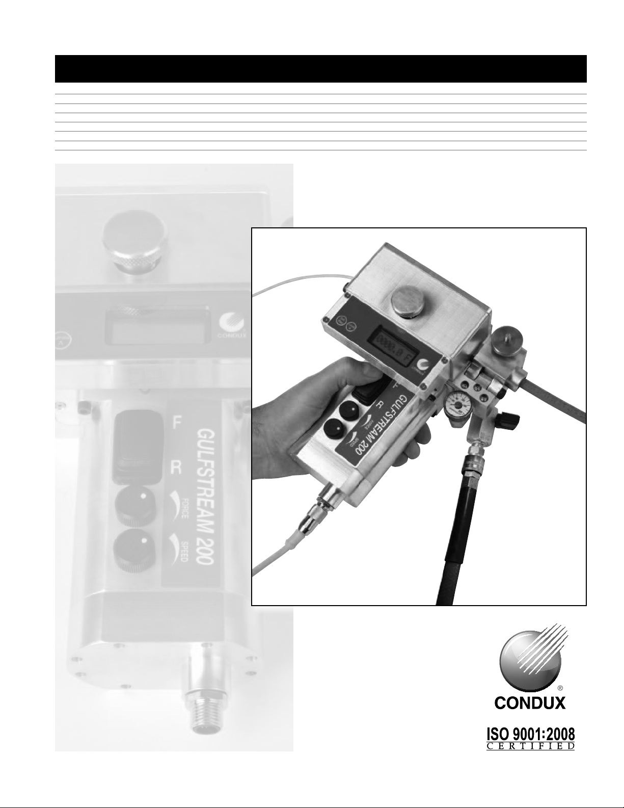
USER'S GUIDE & SAFETY MANUAL
Gulfstream™ 200 Micro Fiber Blower
Page 2
Important Safety Notice
Read and understand all procedures and safety instructions before using the Gulfstream™ 200 Micro
Fiber Blower. Observe all safety information on this page and note specific safety requirements as
explained by procedures in this manual. Failure to follow these instructions could result in serious
personal injury or death.
ADVERTENCIA:
Favor de leer y comprender todas las instucciones de operación y seguridad antes de usar la máquina. Si
Ud. no comprende las instrucciones favor de consultarle a su jefe.
READ MANUAL
FIRST
Save this user’s guide for future reference.
COMMUNICATIONS WITH THE MANUFACTURER
For any information related to the machine (use, maintenance, spare parts) always state Model, Serial
Number, Manufacturing Year and Order. This data can be found in the machine identification table.
Manufacturer:
Condux International Inc.
145 Kingswood Drive
Mankato, MN 56002-0247
1-507-387-6576
Fax 1-507-387-1442
Internet: http://www.condux.com
E-mail: cndxinfo@condux.com
If you have questions on:
SAFETY - OPERATIONS - APPLICATIONS
CALL 1-800-533-2077
2
Page 3

Table of Contents
1
General Information .................................................4
Technical Specifications ............................................. 5
2
A. Condition of Use ............................................. 5
B. Air Compressor Requirements .................................. 5
C. Operational Capacities ........................................ 5
D. Electrical Requirements .......................................5
E. Physical Specifications ........................................ 5
F. Caterpillar Drive Specifications .................................. 5
G. Conduit Coupling Requirements ................................ 5
3
Safe Operating Procedures ........................................... 6
A. Work Area Safety ............................................ 6
B. Pneumatic Devices ........................................... 6
C. Electrical Devices ............................................ 6
4
Unpacking the Blower ...............................................7
A. Blower Components .......................................... 7
Set Up the Blower ..................................................8
5
A. Determine Fiber Size .........................................8
B. Select Cable Seal & Duct Pack .................................8
C. Install Cable Seal & Micro Fiber in Duct Pack ......................9
D. Install Micro Duct ............................................9
E. Install Duct & Fiber in Blower .................................. 10
F. Install Fiber in Tractor Drive & Tighten ...........................10
G. Connect Battery Pack to Blower ...............................11
H. Panel Layout ..............................................11
I. Connect Air Compressor ......................................12
6
Crash Test ....................................................... 13
7
Blower Opterations ................................................14
A. Engage Air ................................................ 14
B. Verify Adjustable Push Force ..................................14
C. Engage Tractor Drive ........................................ 14
D. Adjust Speed ..............................................14
E. Install Fiber ................................................ 14
8
Tear Down Procedures ............................................. 15
A. Remove Power from Unit .....................................15
B. Remove Fiber from Blower .................................... 15
9
Maintenance ..................................................... 16
A. Track Cleaning & Tightening ...................................16
B. Replacement of Drive Belt ....................................16
10
Troubleshooting Guide .............................................. 18
11
Replacement Parts ................................................19
A
Appendices ...................................................... 20
3
Page 4

1.
General Information
The Gulfstream™ 200 is a unique device for inserting fiber optic cable directly into
conduit. The Gulfstream 200 is comprised of an air block and a tractor drive that,
when combined with an air compressor and a battery pack, will propel fiber optic
cable measuring 0.8mm to 5.5mm into an unobstructed, unoccupied, airtight conduit
run at speeds of 0 to 165 ft/min (0-55 m/min). A cable carrier may be placed at the
front end of the cable.
The Gulfstream 200 greatly reduces pulling stress on the cable. The adjustable push
force of the tractor drive will stall the motor if the cable hits an obstruction.
The Gulfstream 200 comes standard with a digital LCD cable meter display, 2 battery
packs, battery charger, duct packs, seal kits and duct lube, all packaged in a foam
filled carrying case.
These operating instructions contain a full description of the Gulfstream 200, which
has been designed for the purpose of feeding fiber cable through conduits of uniform
cross section. The conduit must previously been installed underground or overhead to
receive the fiber optic cable and must be of sufficient length on exit to be received by
the machine. The conduit must be of material with sufficient compression strength for
it to be adequately sealed in the duct clamps of the machine. The conduit must be
airtight up to a pressure of 175psi (12bar). For this purpose, connections of screw,
compression or fusion type must be used. Conduits from 5mm to 12.7mm and fiber
optic cable from 0.8mm to 5.5mm can be accepted by the machine.
The Gulfstream 200 consists of an air block that is made in two halves that clamp
together around the duct clamps. The duct clamps hold a seal that the fiber optic
cable is fed through before entering the duct. The duct clamps and cable seals can be
interchanged to accommodate different conduit and cable sizes. The conduit is
mechanically clamped between the duct clamps at the exit of the air block, preventing
movement in any direction. Built in seals conform around the conduit when clamped.
The fiber cable is fed through the duct by a combined pulling/pushing force. The
pulling force is achieved when pressurized air is fed into the air block and forced into
the duct, generating drag on the fiber cable from airflow passing over it. The pushing
force is created by engaging the tractor drive system. As the tractor drive feeds more
and more fiber cable into the duct, more and more drag force is created by the airflow.
The fiber cable floats in the conduit, minimizing any resistance to being pushed in by
the tractor drive.
The use of the Gulfstream 200 for operations other than those described in this
manual are considered dangerous and are discouraged. Use of this machine for work
other then what is intended, relieves the manufacture from any responsibility, civil or
penal. The manufactures responsibility ceases even when one of the following occurs:
a. Tampering and/or modifications carried out without written approval of
the manufacture.
b. Not using original manufactured replacement parts.
c. Poor maintenance.
d. Not using supplied safety devices or equipment.
e. Connection of this unit to machines and/or parts not produced or
authorized in writing by the manufacture.
4
Page 5

Technical Information
A. CONDITION OF USE:
Temperature from 21° F (-6° C) to 110° F (+43° C) Humidity from 30% to 90% +/- 5%,
Weather conditions relevant to working conditions, Natural and/or artificial lighting of
the work site, minimum 200 lux.
B. AIR COMPRESSOR REQUIREMENTS
1. Pneumatic Pressure: 175 psi (12 bar) Maximum
2. Required Air Flow: 5 - 15 CFM (.14 - .42 m3/min)
3. Conduit Size: 5mm – .50" (12.7mm) OD
4. Air hose fittings: ¼" Quick Connect
C. OPERATIONAL CAPACITIES
1. Pushing Force: 10lbs (45N) Max Push Force
2. Pushing Speed: 165 ft/min (50 m/min) Maximum
3. Cable Sizes: 0.8mm to 5.5mm
4. Conduit Sizes: 5mm, 7mm, 8.5mm, 10mm, 12mm, 12.7mm (
D. ELECTRICAL REQUIREMENTS:
1. Power Requirements: 12Volt (10.8V) DC @ 5Amp Max
2. Power Consumption: 60 Watts Maximum
3. Power Connection: Supplied Battery Pack (includes battery charger)
E. PHYSICAL SPECIFICATIONS
1. Height 4.6" (117 mm)
2. Length 7.5" (190 mm)
3. Width 6.0" (152 mm)
4. Weight 5.7 lbs (2.6 Kg)
F. CATERPILLAR DRIVE SPECIFICATIONS
1. Pushing Force: 10lbs (45N) Max Push Force
2. Pushing Speed: 165 ft/min (50 m/min) Maximum
3. Maximum clamping force: <12 lbf/in (2.1 N/mm)
4. Constant cable centerline design
5. Forward and reverse
6. Independent pushing drive belts with molded urethane cover profiled
for cable 0.8mm to 5.5mm
7. Slide guards
1
⁄2")
2.
G. CONDUIT COUPLING REQUIREMENTS
1. Must withstand maximum air pressure of 175 psi (12 bar)
2. Must withstand axial loading and vibration
3. Must be screw type, compression type, or fusion type
4. Sight holes must be sealed
5. Must fit snugly
6. Conduit ends must be cut off squarely and deburred
7. Conduit must be fully seated into the coupler
8. Couplers should be installed in a straight section of conduit
9. Must be same size conduit
5
Page 6

3.
Safe Operating Practices
Read and understand all procedures and safety instructions before using the
Gulfstream 200. Observe all safety information on this page and note specific safety
requirements as explained by procedures called out in this manual. Failure to follow
these instructions could result in serious personal injury, property damage or death.
A. WORK AREA SAFETY
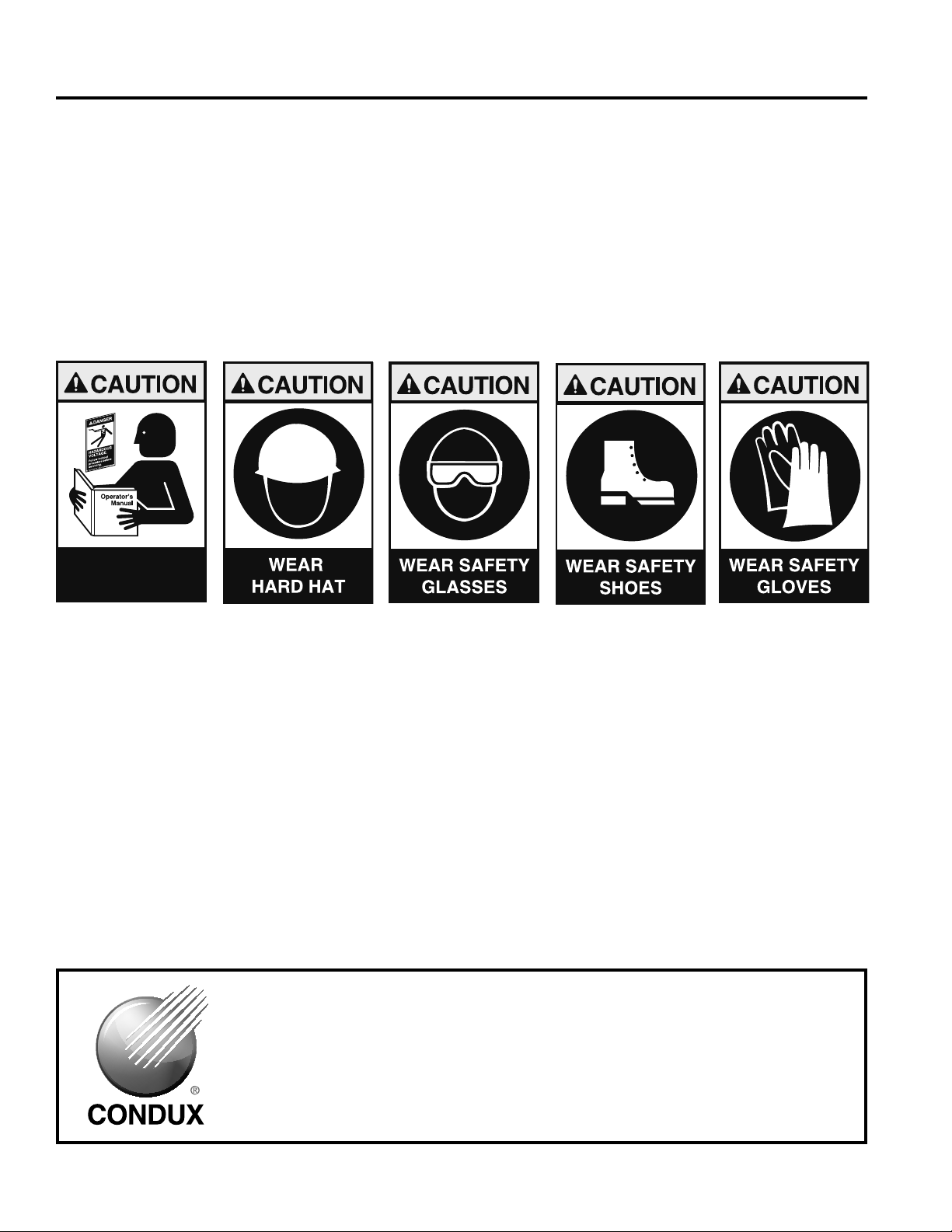
1. Wear personal protective equipment: hard hat, safety glasses, safety shoes,
and leather work gloves.
2. The safe operation of this equipment requires that the operators be on
stable footing.
3. Stay clear of cables or lines under tension.
4. Stay clear of pressurized line and conduit.
5. Use the blower only for its intended purpose.
6. Do not place cable reel too close to unit. Place the reel far enough away from
the unit to ensure proper control.
7. Place cable grip on end of conduit to catch cable carrier and cable.
8. Keep hands away from tractor drive while blower is in operation.
B. PNEUMATIC DEVICES
The Gulfstream 200 is a pneumatic device, using pressurized air to project cable at
high velocities. Please observe the following precautions when operating the blower:
1. Forced air creates flying debris. Always wear personal protective equipment.
Severe personal injury could result.
2. Ensure no personnel are in the destination access vault during the blowing
operation. Severe personal injury could result.
C. ELECTRICAL DEVICES
The motor, controller, and digital display are electrical devices. Electrical shock
hazards exist that could result in severe personal injury or death. Observe the
following precautions to avoid electrical hazards:
1. Do not operate in or near water. This includes setting the unit on a wet surface
or exposing to rain.
2. Do not remove the digital display cover. There are no user-serviceable parts
inside. Refer servicing to qualified service personnel.
3. The drive switch should be in the neutral "center" position before connecting
or disconnecting any cords.
6
Page 7

Unpacking the Blower
A. BLOWER COMPONENTS
Each Gulfstream 200 STD Kit contains the following items:
GS200 Micro Fiber Blower
Battery Pack W/Cord
Rechargeable Battery (2)
Battery Charger
Duct Clamp Insert Assemblies (5-7mm; 8.5-10mm; 12-12.7mm)
Bottle of Lubricant
Common Parts Kit
(Includes: Cable Seals (1.5; 2.0; 2.5; 3.0; 3.5; 4.0; 4.5; 5.0; 5.5 mm)
Blank Seal; O-Ring Kit; Seal Kit; Flat Belt; Hex Key Set; Plastic Case)
NOTE: If any parts are missing: please contact your Condux representative
or call Condux International at 1-800-533-2077 (USA or CANADA), or
1-507-387-6576.
4.
7
Page 8

5.
Set Up the Blower
This manual contains setup and operating instructions for the Gulfstream 200 micro
fiber blower.
A. DETERMINE FIBER SIZE
Determine size of fiber to be installed. To provide optimal traction and grip, if fiber
diameter is 1.5mm or less, the top belt of blower must be changed to a flat belt which
is included in the common parts kit. This flat belt is to be used in combination with the
bottom grooved belt, so that adequate contact and proper push force can be applied
to the fiber. Refer to Section 9 for belt replacement instructions.
B. SELECT CABLE SEAL & DUCT PACK
Choose the correct cable seal and duct pack for the particular application according to
duct and cable size. Refer to Cable Seal and Duct Pack selection charts.
CABLE SEAL SELECTION
CABLE OD (mm) CABLE SEAL KIT PN DUCT PACK PN
0.8-1.5 08783074 08783051; 08783052; 08783053
1.5-2.0 08783057 08783051; 08783052; 08783053
2.0-2.5 08783058 08783051; 08783052; 08783053
2.5-3.0 08783064 08783051; 08783052; 08783053
3.0-3.5 08783059 08783051; 08783052; 08783053
3.5-4.0 08783060 08783052; 08783053
4.0-4.5 08783061 08783052; 08783053
4.5-5.0 08783062 08783052; 08783053
5.0-5.5 08783063 08783052; 08783053
DUCT PACK SELECTION
DUCT OD (mm) DUCT PACK PN
5.0mm 08783051
7.0mm 08783051
8.0mm 08783052
8.5mm 08783052
10.0mm 08783052
12.0mm 08783053
12.7mm 08783053
8
Page 9

C. INSTALL CABLE SEAL & MICRO FIBER IN DUCT PACK
Install the appropriate cable seal on the micro fiber. Make sure orientation of seal on
fiber is correct so that it will seat in the duct pack properly. (See figure 1).
Once the cable seal is positioned properly on the micro fiber, install the cable seal in
the bottom half of the appropriate duct pack. (See figure 2).
Figure 1. Install Micro Fiber in
Cable Seal
Figure 1. Install Cable Seal in
Bottom Half of Duct Pack
Note: The bottom half of the duct pack is designated by a small hole on the
outside of the unit.
D. INSTALL MICRO DUCT
After the cable seal and micro fiber are in place, position the micro duct properly in
the bottom half of the duct pack. (See figure 3).
Once the micro duct is in place, secure the configuration by installing the top half of
the duct pack and pressing firmly together. (See figure 4).
Figure 3. Position Micro Duct
Properly in Duct Pack
Figure 4. Install Top Half of Duct
Pack and Press Together
9
Page 10

E. INSTALL DUCT & FIBER IN BLOWER
Loosen the knob on the Air Block assembly. Open the air block cover. Insert the duct
pack assembly into the air block as shown. (See figure 5). Close air block cover and
hand tighten knob to secure. (See figure 6).
Figure 5. Insert Duct Pack
Figure 6. Tighten Knob
Assembly into Air Block
F. INSTALL FIBER IN TRACTOR DRIVE AND TIGHTEN
Feed the micro fiber between tractor drive and through the rear fiber guide.
(See figure 7). Tighten tractor drive using the down screw to ensure even pressure on
the micro fiber. (See figure 8). Do not over tighten.
10
Figure 7. Feed Micro Fiber
Between Tractor Drive and
Rear Fiber Guide
Figure 8. Tighten Tractor Drive
Down Screw
Page 11

G. CONNECT BATTERY PACK TO BLOWER
Attach power supply cable to blower unit and battery pack, tighten connections.
(See figure 9). Once you have the supply cable connected, install the battery in
battery pack as shown. (See figure 10).
Figure 9. Attach Battery Pack
Figure 10. Install Battery
Cable to Blower Unit
H. PANEL LAYOUT
A description of each of the buttons and displays for the Gulfstream 200 micro fiber
blower control box appears below. (See figure 11).
Figure 11. Panel Layout
Sel/Res:
1. Push Sel/Res to toggle between distance, rate, and total
2. Hold sel/Res to reset the distance
Units:
1. Toggles between US and Metric units for all modes
11
Page 12

I. CONNECT AIR COMPRESSOR
NOTE: Ensure the air control valve is off before connecting the air hose.
Attach the air compressor hose to the air compressor if necessary. Then
connect the compressor hose to the blower unit. (See figure 12). The unit uses a
standard quick connect air compressor coupling.
NOTE: Route all hoses properly to prevent tripping over them. (See figure 12A).
Figure 12. Connect Air
Compressor Hose
Figure 12A. Typical Setup
12
Page 13

Crash Test
Cable Crash Testing is a very quick and easy step to be completed before attempting
the installation of cable with the Gulfstream 200. This test is necessary to set the
electronic push force control of the motor below the point that it may cause cable
damage as a result of over pushing or encountering an obstruction in the
sub-duct system.
Every cable has different pushing values and these values vary depending on
duct I.D. Example: A cable with a crash test value of 75 bar in 33 mm I.D. duct,
may have a crash value of only 60 bar in a 40 mm I.D. duct. This is because the
area of lateral movement is larger as the duct size increases.
!CAUTION: Always wear protective equipment: hard hat, safety glasses, safety
shoes and work gloves.
NOTE: The electronic push force adjustment will have little effect on the installation
speed of the blowing unit. This is an adjustment to prevent damage to the cable that
can be caused by excessive pushing force.
IMPORTANT: For the Crash Test to work properly use the same size cable and duct
that will be used for the job.
6.
Set the electronic push force adjustment on the Gulfstream 200 using the following
procedure:
a. Attach 12' (4 m) of duct to the Gulfstream 200 with 15' (5 m) of fiber optic cable
(See figures 3-8) using the appropriate duct pack and cable seal.
b. Set the adjustable push force to about half way of the maximum.
c. Install Conduit Pulling Eye or place your thumb or finger over the receiving end
of the duct.
d. Push cable through the duct until it stops against the Pulling Eye
e. Place a mark on the Cable about 1" (25 mm) behind the Rear Guide
f. From the Rear Guide, pull out approximately 8' (2.4 m) of cable from the blower
g. Lower the Tractor Drive
h. Turn on the tractor drive and allow cable to move until it stops. Note the push
force setting.
i. Increase push force slightly
j. Repeat steps f through i until the cable folds over or you reach maximum push
force setting. If the tractor drive belt is slipping on the cable, tighten the tractor
drive down screw and repeat steps f through i. You will notice cable fold-over
because the line drawn on the cable will disappear inside the machine or duct
k. Reduce push force slightly if cable fold-over has occurred and test once more
to ensure no fiber fold-over or damage occurs at this setting. This will be
maximum push force setting for this application
l. Reset the speed to the minimum and remove test fiber and duct
m. Test complete
13
Page 14

Blower Operations
A. ENGAGE AIR
Start compressor. Slowly open the air control valve to allow air flow to the air block by
turning the control valve knob clockwise.
7.
IMPORTANT: Do not exceed 175 PSI when operating the unit.
!WARNING: Forced air creates flying debris. Always wear personal
protective equipment.
B. VERIFY ADJUSTABLE PUSH FORCE
Verify adjustable push force is set to the established crash test value and the speed is
at minimum.
C. ENGAGE TRACTOR DRIVE
The tractor drive can be operated in forward and reverse. For installation, engage the
tractor drive in forward by depressing the tractor drive control switch to the “F” position
as shown. (See figure 13).
D. ADJUST SPEED
Use the Speed control knob to adjust the tractor drive speed to ensure smooth
installation and match the amount of air pressure being used so that the forces are
working together, not against one another. (See figure 14). Counterclockwise
increases speed and clockwise decreases speed.
E. INSTALL FIBER
14
Figure 13. Tractor Drive Forward
Figure 14. Adjust Speed Control
Page 15

Tear Down Procedures
!WARNING: Air Block Assembly contains compressed air when blower is
operated. Opening Air Block while under pressure may cause serious
personal injury. Ensure blower is depressurized before removing Air
Block cover.
A. REMOVE POWER FROM UNIT
1. Turn off compressed air by closing the Air Control Valve at the blower.
(See figure 15). Shut off air at the compressor and decompress air hose.
Depressurize the air block by turning the air control valve counterclockwise.
(See figure 16). Remove air hose when system is relieved of pressure.
8.
Figure 15. Turn Off Air
2. Raise Tractor Drive by turning down screw counterclockwise. (See figure 17).
3. Disconnect battery cable
B. REMOVE FIBER FROM BLOWER
1. Loosen the knob on the Air Block assembly and open the air block.
(See figure 18).
Figure 16. Depressurize Air Block
Figure 17. Raise Tractor Drive
2. Remove duct pack assembly.
3. Open duct pack assembly and remove the conduit.
Figure 18. Loosen Knob
15
Page 16

9.
Maintenance
Procedure Daily Weekly Monthly 60 Days 90 Days
Clean all assemblies and
components thoroughly
Inspect fasteners and screws X X X X X
Check Belt Tension. Replace if
excess wear has occured
A. TRACK CLEANING AND TIGHTENING
1. Inspect track before and after each use.
2. Clean after each use, or when necessary. Remove the top assembly to clean
thoroughly by:
•Unscrewingtractordownscrewalltheway
•Separatingthetwohalves–notepartsbeingdisassembledtoease
reassembly
B. REPLACEMENT OF THE DRIVE BELT
The drive belts need to be replaced when the machine is unable to tractor drive the
specified range of cable diameters. Only genuine spares should be used otherwise the
machine may be unsafe and void warranty.
X X X X X
X X X X X
1. Remove front cover plate and plastic guard from top half assembly
(See figure 19).
Figure 19. Remove Front Cover Plate
16
Page 17

2. Loosen tension screw on side of top assembly with allen wrench until the pulley
can slide enough to free the belt (See figure 20).
Figure 20. Loosen Tension Screw
3. Remove the belt (See figure 21).
Figure 21. Remove the Belt
4. Install new belt.
5. Tighten tension screw on side of top assembly to 40 in-oz.
6. Repeat steps for bottom assembly (if required).
17
Page 18

Troubleshooting Guide
Problem Solution
10.
Cable becomes jammed in the conduit
system.
Tractor Feed does not pull the cable off
the reel.
Blower cuts out with electronic error of
minspeed or highspeed error.
1. Inform the people at the other end of
the conduit that a problem has been
experienced and the operator is going to
shut down the system.
2. Shut off the pneumatic air supply with the
Air Control Valve turning it to the 9 o’clock
position, allowing the air pressure to be
depressurized from the conduit and the
air block.
3. Using the counter or the measurement on
the cable, determine where the
blockage might be located.
4. Notify supervisor about problem and
determine a solution accordingly.
Assist the reel by pushing it, and/or by pulling
the cable off the reel.
Blower has exceeded the minimum or
maximum speed allowance. Adjust speed
accordingly, or wipe cable clean from mud
and dirt.
The cable run is hard to restart after
having stopped.
Tractor feed doesn’t start.
Put air to the system with the track down. The
tractor feed can be restarted after the air
pressure has increased and stabilized.
Tractor Drive switch is in the neutral "center"
position. Select forward or reverse.
18
Page 19

Gulfstream 200 Replacement Parts
02290722
02290724
02290725
02290727
02290834
08230675
08783026
08783065
08783070
08783075
08783051
08783052
08783053
KNURLED THUMB KNOB(BRASS)-BELT CLAMP FORCE
MINI-GAUGE - 200PSI
MINI BALL VALVE 1/8NPT
3PIN CORDSET
KNURLED THUMB KNOB-DUCT CLAMP
POLY LUBRICANT 6PAC - 8OZ BOTTLE
BATTERY CLIP ASSEMBLY
KIT, BELT V-GROOVE GS200 (2 Belts)
KIT, BELT SMALL FIBER GS200 (1 Flat/1 V-Groove)
KIT, BELT FLAT GS200 (2 Belts)
DUCT CLAMP INSERT ASSY 5.0-7.0MM
DUCT CLAMP INSERT ASSY 8.5-10.0MM
DUCT CLAMP INSERT ASSY 12.0-12.7MM
Battery & Charger Replacement Parts
US
(08783050)
INTERNATIONAL
(08783050-EU)
08783055 BATTERY, DEwALT 12V LI-ION
08783056 CHARGER, BATTERY DEwALT 12V LI
02290858 BATTERY, DEwALT 10.8V EURO
02290859 CHARGER, BATTERY DEwALT 10.8V EURO
11.
Common Parts Kit
08783072 COMMON PARTS KIT (INCLUDES THE FOLLOwING)
08783054 1 PLASTIC CASE
02290837 1 HEx KEY SET
08783074 1 1.5MM CABLE SEAL KIT (5 PCS)
08783057 1 2.0MM CABLE SEAL KIT (5 PCS)
08783058 1 2.5MM CABLE SEAL KIT (5 PCS)
08783064 1 3.0MM CABLE SEAL KIT (5 PCS)
08783059 1 3.5MM CABLE SEAL KIT (5 PCS)
08783060 1 4.0MM CABLE SEAL KIT (5 PCS)
08783061 1 4.5MM CABLE SEAL KIT (5 PCS)
08783062 1 5.0MM CABLE SEAL KIT (5 PCS)
08783063 1 5.5MM CABLE SEAL KIT (5 PCS)
08783071 1 BLANK CABLE SEAL KIT (5 PCS)
08783076 1 SEAL KIT (INCLUDES ADHESIVE)
08783077 1 O-RING KIT (5 PCS)
SEE BELT KITS 1 FLAT BELT
19
Page 20

A.
APPENDIX
Gulfstream 200 Charts & Drawings
ITEM PART NO DESCRIPTION QTY
1 02290727 CORDSET, 3 PIN, IM, FS TO MS 1
2 08783026 CLIP, BELT-BATTERY GULFSTREAM 200 1
20
Page 21

ITEM PART NO DESCRIPTION QTY
1 02288203 CAPSCREW, #6-32X0.50 SHSTALY PL 4
2 02288240 CAPSCREW, #6-32X0.37 BHSS 18-8 3
3 02288636 FITTING, HYD 02-NPT_M; 02-NPT_F 90 2
4 02290723 PLUNGER, SPRING #4-48 .1-.5# 2
5 02290724 GAUGE, MINI 1/8 NPT 200 PSI 1
6 02290725 VALVE, MINI 1/8 NPT BALL WEDGE 1
7 02290726 COUPLING, QC 1/8 NPT 1/4 CPLG 1
8 02290739 SCREW, SHOULDER .250 DIA-.875 1
9 02290740 SCREW, SHOULDER .188 DIA-.500 1
10 02290749 SCREW, SHOULDER .125 #4-40 2
11 02290834 NUT, KNURLED THUMB 10-32 THREADS 1
12 08783020 CLAMP, AIRBLOCK GULFSTREAM 200 1
13 08783025 BLOCK, MANIFOLD GULFSTREAM 200 1
14 08783032 BOLT, SWING #10-32 X 2.0" SS 1
15 08783034 GUARD, FRONT GULFSTREAM 200 2
16 08783035 GUARD, WINDOW GULFSTREAM 200 1
21
Page 22

4
10
15
5
13
2
17
21
9
20
11
3
6
8
14
16
10
19
15
9
20
11
7
1
18
3
12
5
22
22
Page 23

ITEM PART NO DESCRIPTION QTY
1 02152600 CAPSCREW, #2-56X0.50 SHSTALY PL 2
2 02269674 RING, RETAINING 0.250 EXTERNAL A/R
3 02288269 CAPSCREW, 0.25-20X1.25 SHSTALY PL 2
4 02290722 KNOB, BRASS KNURLED, 1/4" SHAFT 1
5 02290728 SPRING, COMPRESS .062-.500-.500 2
6 02290729 SPRING, COMPRESS .041-.360-.750 4
7 02290738 SPRING, COMPRESS .016-.125-.500 2
8 02290742 SETSCREW, .138-32 X .37 HXSO SS 2
9 02290743 CAPSCREW, #2-56X0.188 CSSS 18-8 6
10 08783065 KIT, BELT V-GROOVE (2BELTS) GS200 1
08783070 KIT, BELT V-GROOVE/FLAT (1EA) GS200 OPT
08783075 KIT, BELT FLAT (2BELTS) GS200 OPT
11 08783081 KIT, TAKE-UP SHAFT ASSY - GS200 2
12 08783004 BLOCK, LOWER GULFSTREAM 200 1
13 08783082 BLOCK, UPPER (ASSY)-GS200 (INCLUDES BEARINGS) 1
14 08783006 PLATE, FRAME GULFSTREAM 200 1
15 08783008 PULLEY, T5 25T, GULFSTREAM 200 4
16 08783009 FLANGE, GUIDE GULFSTREAM 200 1
17 08783010 SHAFT, TENSION ADJUSTMENT GS200 1
18 08783011 SHAFT, GUIDE 1/4" FLAT GS200 2
19 08783018 SLEEVE, BUSHING, 3/8" GULFSTREAM 200 1
20 08783030 PLATE, COVER BELT TENSION GULFSTREAM 200 2
21 08783079 SHAFT, SENSOR (ASSY) GS200 1
22 12001302 NUT, 0.37-16 HEX ST GR5 CZ 1
23
Page 24

Condux International, Inc.
P.O.Box247•145KingswoodDrive,Mankato,MN56002-0247USA
1-507-387-6576•1-800-533-2077•FAX1-507-387-1442
www.condux.com•e-mail:cndxinfo@condux.com
© Copyright 2013, Condux International, Inc.
Printed in USA
Literature Part Number: 08783049
Revision Number: 1.1
 Loading...