

Page 1
USER'S GUIDE & SAFETY MANUAL USER'S GUIDE & SAFETY MANUAL
Extension Frame
Page 2
Important Safety Notice
Read and understand all procedure and safety instructions before using the Condux CableGlider Cable Puller
Extension Frame. Observe all safety information on these pages and note specific safety requirements as
explained by procedures called out in this manual. Failure to follow these instructions could result in serious
personal injury or death.
ADVERTENCIA:
Favor de leer y comprender todas las instrucciones de operación y seguridad antes de usar la máquina. Si Ud. no
comprende las instrucciones favor de consultarle a su jefe.
READ MANUAL
FIRST
WEAR
HARD HAT
WEAR SAFETY
GLASSES
WEAR SAFETY
SHOES
Save this user’s guide for future reference.
WEAR SAFETY
GLOVES
CONDUX
2
If you have questions on:
SAFETY - OPERATIONS - APPLICATIONS
®
CALL 1-800-533-2077
Page 3
General Information
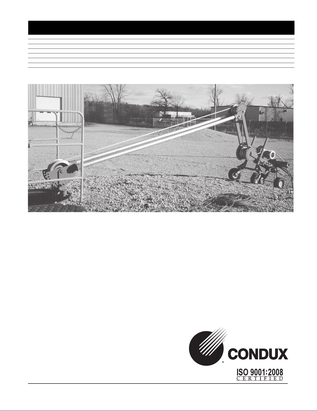
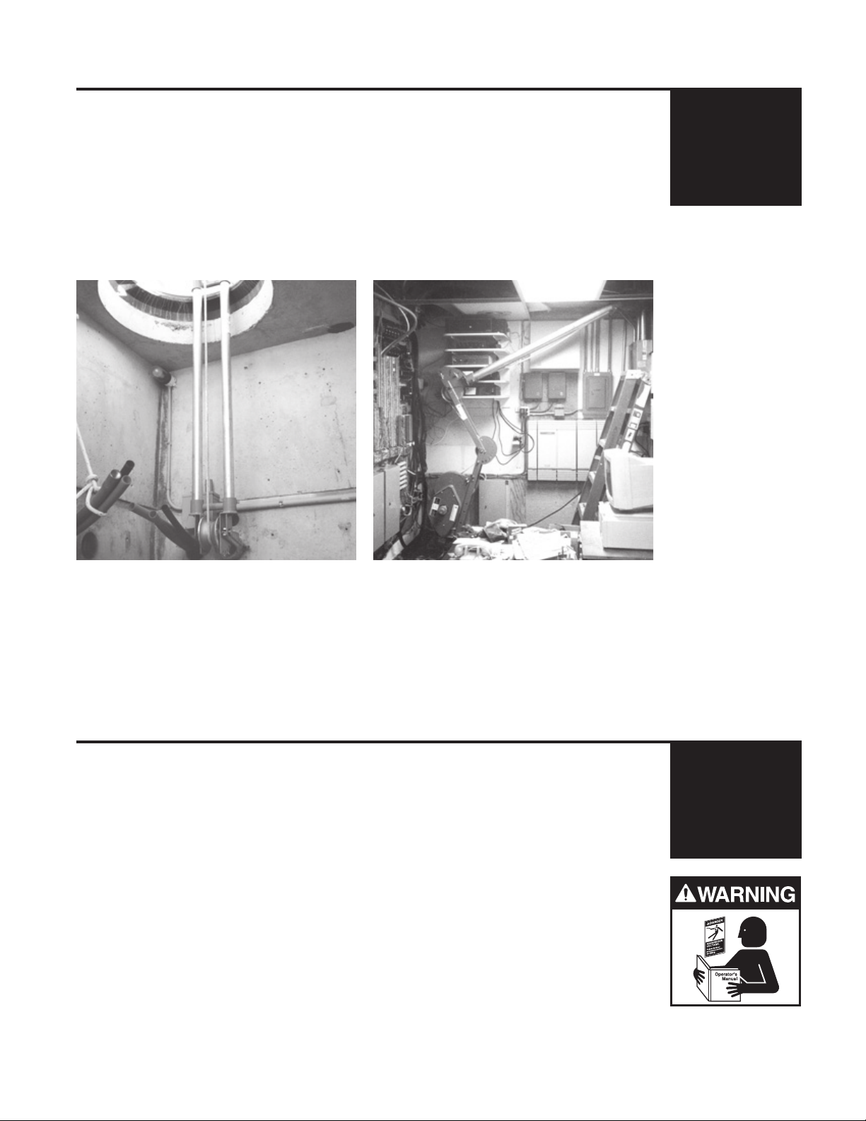
The Condux CableGlider Cable Puller Extension Frame is designed for pulling jobs were a
longer reach and added stability are necessary. It is ideal for pulling from deep manholes
(Figure 1) or high overhead ducts (Figure 2). Extra slack can be pulled with the Extension
Frame when needed for termination.
The extension frame is designed for use with the Condux CableGlider Cable Puller and its
accessories. 2" Sch 40 GRC steel duct for the Extension Frame is not included.
Figure 1
Figure 2
1.
CableGlider Cable Puller
Reference
IMPORTANT: The user of the Extension Frame must have a
complete understanding of the Condux CableGlider Cable Puller.
Read and understand operator’s instructions and safety manual
for the CableGlider Cable Puller before attempting to use it or the
extension fame.
2.
3
Page 4
3.
Components
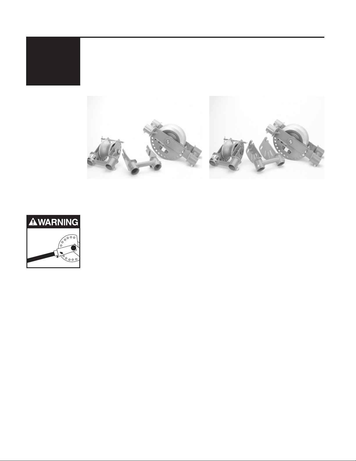
Two Extension Frame Kits available- One for Plus and HD CableGlider Cable Pullers
(Figure 3) and One for the STD CableGlider Cable Puller (Figure 4). Each kit contains the
following items:
1 Cable Puller Adapter
1 Center Joint
1 Duct End Joint
Use Only
2" Sch 40
GRC Steel Duct
Center Joint
Duct End Joint
Cable Puller Adapter
Figure 3
In addition to these items, a corresponding conduit adapter & retaining fork (both included
with CableGlider Cable Puller) and 2" Sch 40 GRC steel duct (not included) are needed.
Duct End Joint
Cable Puller Adapter
Figure 4
Center Joint
!WARNING: Only use 2" Sch 40 GRC steel duct with Extension
Frame. Thin wall steel duct (EMT) or PVC duct will not withstand
the loads generated and will bend and break causing serious
personal injury or death.
The Cable Puller Adapter attaches to the first pivot arm of the CableGlider Cable Puller.
NOTE: The second pivot arm on the Plus and HD CableGlider Cable Puller
models must be removed before using the Extension Frame. Attach Cable Puller
Adapter to first pivot arm only.
The Extension Frame Center Joint is a directional joint placed between the CableGlider
Cable Puller and the conduit location. It provides a range of almost 180 degrees of
adjustment to the Extension Frame configuration. The Center Joint can be used, for
example, when pulling from a deep manhole. The Center Joint is not needed in every
configuration.
The Duct End Joint connects to the Retaining Fork/Conduit Adapter. It too is directionally
adjustable to meet the configuration needs of the pull.
IMPORTANT: The Condux CableGlider Cable Puller Extension Frame provides a
nearly infinite number of possible configurations. Several things, however,
should be kept in mind when configuring and assembling the Extension Frame:
1. Cable Puller Stability
2. Amount of slack desired
3. The proximity of the Cable Puller and the conduit
NOTE: The order of the following assembly instructions may vary depending on
job situations and configuration requirements. Always determine the approximate Extension Frame configuration for the particular pull before assembling.
4
Page 5
Assembly Instructions
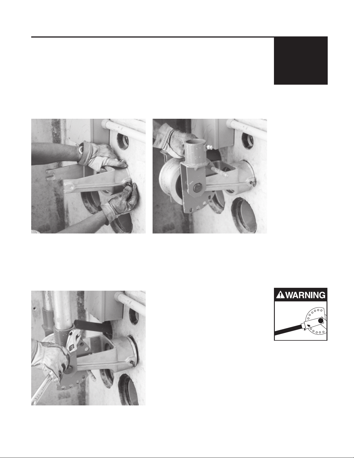
A. PREPARE CONDUIT FOR DUCT END JOINT
Corresponding size Conduit Adapter fits into Retaining Fork and is secured by tightening
thumb screws. Conduit Adapter is then inserted into conduit (Figure 5). (Conduit Adapters
and Retaining Fork for 2", 3", 3 1/2" and 4" conduit are included with CableGlider Cable
Puller. Larger sizes are available from Condux.)
B. ATTACH DUCT END JOINT TO RETAINING FORK
The Extension Frame Duct End Joint attaches to the Retaining Fork on milled slots and
is secured with a locking pin. Duct End Joint can be adjusted for specific pull
configurations and is secured with a locking pin (Figure 6).
4.
Figure 5
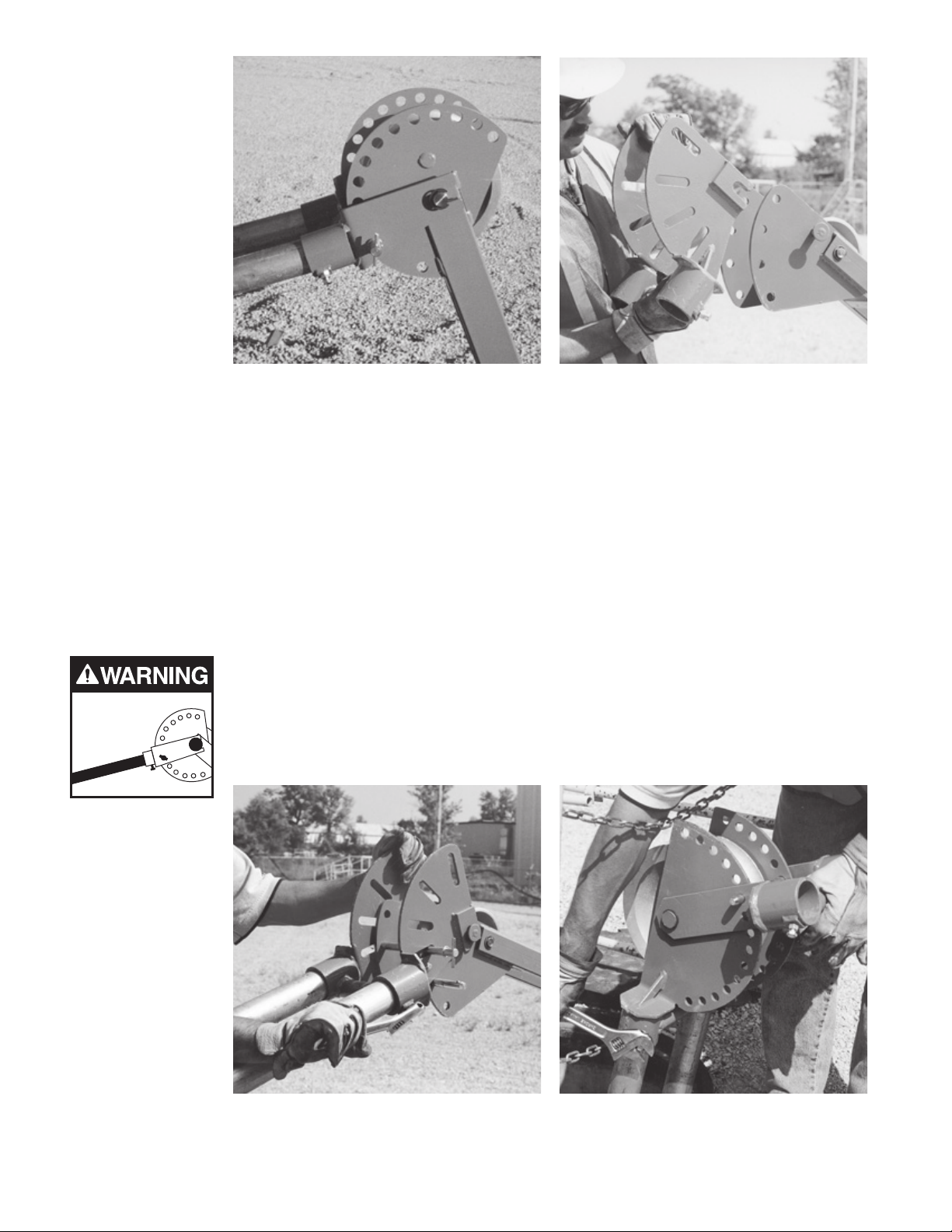
C. INSERT 2" GRC STEEL DUCT IN DUCT END JOINT
The two pieces of 2" Sch 40 GRC steel duct connect to the Extension Frame Duct End
Joint in cylindrical duct ports and are secured by tightening cap screws and lock nuts
(Figure 7).
!WARNING: Only use 2" Sch 40
GRC steel duct with Extension
Frame. Thin wall steel duct (EMT)
or PVC duct will not withstand the
loads generated and will bend
and break causing serious
personal injury or death.
Figure 6
Use Only
2" Sch 40
GRC Steel Duct
Figure 7
5
Page 6
Use Only
2" Sch 40
GRC Steel Duct
Figure 8
Figure 9
D. ATTACH CABLE PULLER ADAPTER TO CABLE PULLER
The HD and Plus (Figure 8), & STD Extension Frame Cable Puller Adapters (Figure 9)
attach to the corresponding CableGlider Cable Puller pivot arm on milled slots. The Cable
Puller Adapter can be adjusted and is secured with locking pins.
IMPORTANT: The adapter will only attach to the first pivot arm. The second pivot
arm must be removed from HD and Plus CableGlider Cable Puller models before
attaching the Extension Frame Cable Puller Adapter.
E. INSERT 2" GRC STEEL DUCT IN CABLE PULLER ADAPTER
The 2" two pieces of Sch 40 GRC steel duct connect to the Cable Puller Adapter in the
cylindrical duct ports and are secured by tightening the cap screws and lock nuts
(Figure 10).
!WARNING: Only use 2" Sch 40 GRC steel duct with Extension
Frame. Thin wall steel duct (EMT) or PVC duct will not withstand
the loads generated and will bend and break causing serious
personal injury or death.
Figure 10
Figure 11
6
Page 7
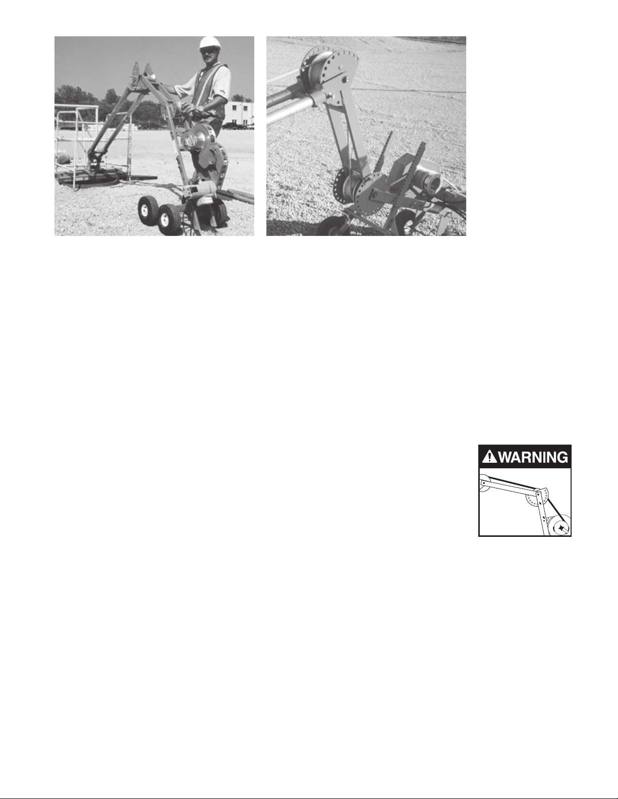
Figure 12
Figure 13
F. CONNECT USING CENTER JOINT
If applicable, the Center Joint can be adjusted to match Extension Frame configuration
and is secured with locking pins. The 2" Sch 40 GRC steel duct from the Duct End Joint
and from Cable Puller Adapter connects to the Extension Frame Center Joint in the
cylindrical duct ports and is locked in place by tightening the cap screws and lock nuts
(Figure 11).
NOTE: When Center Joint is not needed, 2" Sch 40 GRC steel duct from Duct
End Joint connects directly to Cable Puller Adapter in the cylindrical duct ports
and is locked in place by tightening the cap screws and lock nuts (Figure 12).
G. THREAD CABLE PULLING ROPE
Pulling rope must be thread from the conduit across all sheaves on the Extension Frame
and through the CableGlider Cable Puller (Figure 13). Please refer to CableGlider Cable
Puller manual for proper Cable Puller set up.
!WARNING: Pulling rope must contact ALL sheaves on frame and
puller when threading. Puller frame will bend and break causing
serious personal injury or death if not threaded properly.
H. ENSURE CONFIGURATION INTEGRITY/STABILITY
Make sure that all cap screws, thumb screws and lock nuts are secure. Make sure all locking pins are in place. Make sure all connections are made properly.
I. OPERATE CAREFULLY
Operate CableGlider Cable Puller as per Cable Puller manual.
7
Page 8

5.
Warranty Information
Condux International, Inc. extends the following warranty to the original purchaser of these
goods for use, subject to the qualifications indicated:
Condux International, Incorporated warrants to the original purchaser for use that the
goods or any component thereof manufactured by Condux International will be free from
defects in workmanship for the period of one year from the date of purchase, provided
such goods are installed, maintained, and used in accordance with Condux’s written
instructions.
Components not manufactured by Condux International but used within the assembly
provided by Condux International are subject to the warranty period as specified by the
individual manufacturer of said component, provided such goods are installed, maintained
and used in accordance with Condux’s and the original manufacturer’s written instructions.
Condux’s sole liability and the purchaser’s sole remedy for a failure of goods under this
limited warranty, and for any and all claims arising out of the purchase and use of the
goods, shall be limited to the repair or replacement of the goods that do not conform to
this warranty.
To obtain repair or replacement service under the limited warranty, the purchaser must
contact the factory for a Return Material Authorization (RMA). Once obtained, send the
RMA along with the defective part or goods, transportation prepaid, to:
Condux International, Inc.
145 Kingswood Drive
Mankato, MN 56001 USA
THERE ARE NO EXPRESS WARRANTIES COVERING THESE GOODS OTHER THAN
AS SET FORTH ABOVE. THE IMPLIED WARRANTIES OR MERCHANTABILITY AND
FITNESS FOR A PARTICULAR PURPOSE ARE LIMITED IN DURATION TO ONE YEAR
FROM DATE OF PURCHASE.
CONDUX ASSUMES NO LIABILITY IN CONNECTION WITH THE INSTALLATION OR
USE OF THIS PRODUCT, EXCEPT AS STATED IN THIS LIMITED WARRANTY.
CONDUX WILL IN NO EVENT BE LIABLE FOR INCIDENTAL OR CONSEQUENTIAL
DAMAGES.
®
Condux International, Inc.
P.O. Box 247 • 145 Kingswood Drive, Mankato, MN 56002-0247 USA
1-507-387-6576 • 1-800-533-2077 • FAX 1-507-387-1442
http://www.condux.com • cndxinfo@condux.com
© Copyright 2012, Condux International, Inc.
Printed in USA
Literature Part Number: 08674999
Revision Number: 1.1
 Loading...