

Page 1
INSTALLATION GUIDE INSTALLATION GUIDE INSTALLATION GUIDE
Crimp-On Pulling Eyes
CONDUX
Page 2
Important Safety Notice
Read and understand all procedures and safety instructions before installing Condux Cable
Pulling Eyes. Observe all safety information on this page and note specific safety requirements as
explained by procedures called out in this manual. Failure to follow these instructions could result
in serious personal injury or death.
ADVERTENCIA:
Favor de leer y comprender todas las instucciones de operación y seguridad antes de usar la
máquina. Si Ud. no comprende las instrucciones favor de consultarle a su jefe.
Save this user’s guide for future reference.
If you have questions on:
SAFETY - OPERATIONS - APPLICATIONS
CALL 1-800-533-2077 or 1-507-387-6576
2
Page 3

Table of Contents
General Information . . . . . . . . . . . . . . . . . . . . . . . . . . . . . . . . . . . . . . . . . . .
..4
a. The Condux Pulling Eye . . . . . . . . . . . . . . . . . . . . . . . . . . . . . . . . .
4 b.
Crimper Kit and Accessories. . . . . . . . . . . . . . . . . . . . . . . . . . . . . . 5
c. Types of Condux Pulling Eyes. . . . . . . . . . . . . . . . . . . . . . . . . . . . .
6
Installing a Crimp-On Telephone Pulling Eye. . . . . . . . . . . . . . . . . . . . . . . . .7
a. Preparing the Cable - The Centering Tool. . . . . . . . . . . . . . . . . . . .7
b. Telephone Cable Pulling Eye Selection. . . . . . . . . . . . . . . . . . . . . .8
c. Marking the Cable Before Installation . . . . . . . . . . . . . . . . . . . . . . 9
d. Driving the Pulling Eye onto the Cable. . . . . . . . . . . . . . . . . . . . . ..9
e. Crimper Die Selection. . . . . . . . . . . . . . . . . . . . . . . . . . . . . . . . . . .
10
f. Crimper Cable Selection. . . . . . . . . . . . . . . . . . . . . . . . . . . . . . . . .
10
g. Attaching the Crimper Cable. . . . . . . . . . . . . . . . . . . . . . . . . . . . .
.10
h. Crimping the Pulling Eye. . . . . . . . . . . . . . . . . . . . . . . . . . . . . . . .
.12
i . Procedure for Gel or Grease Filled Cable. . . . . . . . . . . . . . . . . . .13
Page 4
1.
General Information
A. THE CONDUX PULLING EYE
A pulling eye for telephone cable is made of a forged eye pad, a length of tube,
and a barbed spike. When crimping on the end of a cable, it allows you to
successfully pull cable into any type of duct system.
The pulling eye is driven onto the end of the cable and crimped into place.
The crimp takes place between the barbs on the spike, which is inside of the
tube and the tube itself. This crimp grips 100% of the conductors and assures
maximum pulling strength when pulling cable into your duct system. The
pulling eye also seals the end of the cable. This will keep pressure in and
water out.
4
Page 5
B. CRIMPER KIT AND ACCESSORIES
Items needed to crimp pulling eyes onto cable:
1. The Crimper Kit - The kit has capabilities of crimping pulling eyes with inside diameters of 0.555
to 3.620 inches. The kit contains the crimper dies, crimper cables, crimper base and hydraulic
ram, cable guard, and the hydraulic hose and couplings. Condux part number 08920000.
2. Driving Tool - The driving tool is used for driving the pulling eye onto the cable. This is an
important tool to keep the pulling eye from being damaged during installation.
3. Centering Tool - By driving the centering tool into the end of the communications cable, you
force some of the grease out and separate the wire pairs. This provides a passage in the center
of the cable for the pulling eye spike to follow into.
4. Hydraulic Pump - The pump is used to supply hydraulic pressure to the crimper ram which
crimps the eye to the cable.
5. Measuring Tape - The measuring tape is used for determining the size of the cable and for
ensuring complete seating of the eye on the cable.
6. Sledge Hammer - For driving the centering tool into the cable and for driving the pulling eye
onto the cable when using the driving tool.
5
Page 6
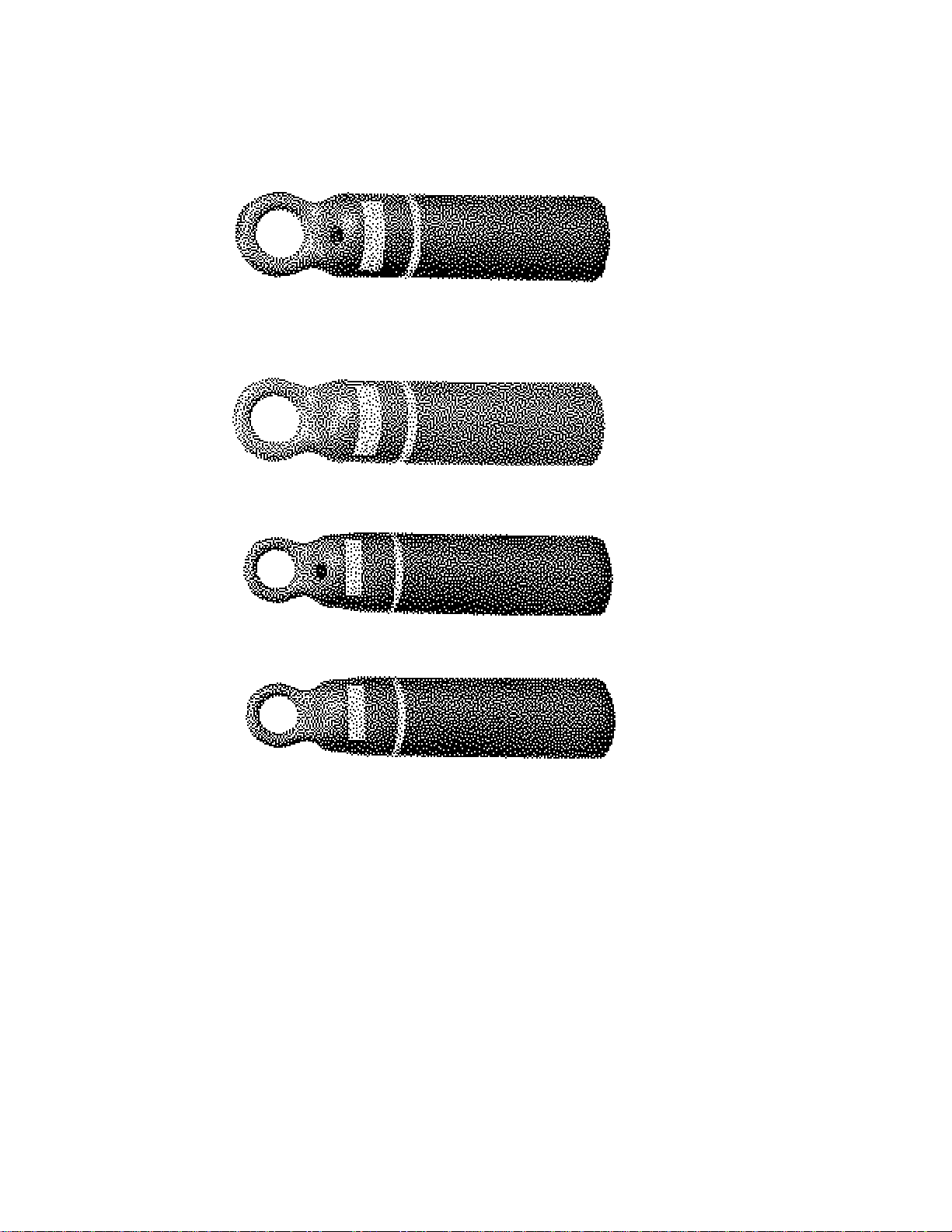
C. TYPES OF CONDUX PULLING EYES
Use the following to determine the type of pulling eye you need:
3-Crimp pulling eye with port - for standard cut length cables of under 600 feet that are gel or
grease-filled or are to be pressurized.
3-Crimp pulling eye without port - for standard cut length cables of under 600 feet.
4-Crimp pulling eye with port - for all types of gel or grease filled or pressurized cable.
4-Crimp pulling eye without port - for air core cable when you are not going to pressurize cable
from the pulling eye end.
6
Page 7
Installing a Crimp-On Telephone
Pulling Eye
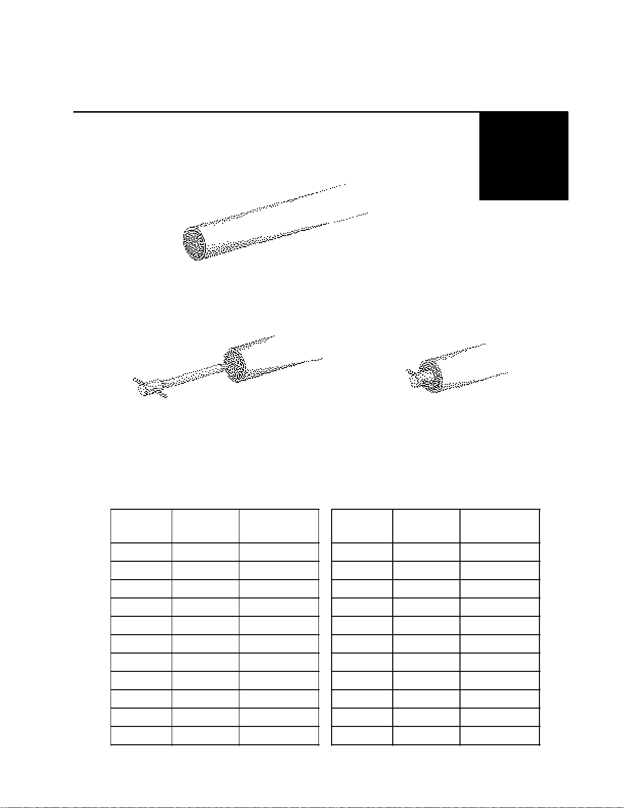
A. PREPARING THE CABLE - THE CENTERING TOOL
2.
First, it is recommended that you square off the end of the cable. This ensures that the pulling
eye will go on as far as possible.
From the chart below, locate the proper centering tool. Place the centering tool on the end of the
cable as close to the center as possible. Drive the centering tool into the cable up to the head of
the centering tool. This will push some of the grease from the cable and separate the wire pairs,
making way for the spike inside of the pulling eye.
Cable O.D.
Up To (in.)
1.0552708945011 2.402 6108945027
1.1522908945011 2.527 6408945027
1.2773208945015 2.652 6808945027
1.40236089450152.7777008945027
1.52739089450152.9027408945029
1.65242089450212.9957608945029
1.77745089450213.1407908945034
1.90249089450213.2458308945034
2.02751089450213.3708608945034
2.15255089450213.4958908945034
Cable O.D.
Up To (mm)
Centering Tool
Part Number
Cable O.D.
Up To (in.)
Cable O.D.
Up To (mm)
Centering Tool
Part Number
2.27732089450273.6209208945043
7
Page 8

B. TELEPHONE CABLE PULLING EYE SECTION
With the centering tool still in the cable, measure the diameter of the cable. With this measure ment, select the proper pulling eye size from the chart below. The inside diameter of the pulling
eye should be slightly larger than the outside diameter of the cable you are crimping a pulling eye
onto.
Inside Dia.
of Pulling
Eye (in.)
Inside Dia.
of Pulling
Eye (mm)
4-Crimp Pulling
Eye Without
Valve Port
3-Crimp Pulling
Eye Without
Valve Port
4-Crimp Pulling
Eye With Valve
Port
3-Crimp Pulling
Eye With Valve
Port
0.95024 08911009
1.05527 08911010
1.15229 08910011089110110891901108919511
1.27732 08910012089110120891901208919512
1.40236 08910014089110140891901408919514
1.52739 08910015089110150891901508919515
1.65242 08910016089110160891901608919516
1.77745 08910017089110170891901708919517
1.90249 08910019089110190891901908919519
2.02751 08910020089110200891902008919520
2.15255 08910021089110210891902108919521
2.27732 08910022089110220891902208919522
2.40261 08910024089110240891902408919524
2.52764 08910025089110250891902508919525
2.65268 08910026089110260891902608919526
2.77770 08910027089110270891902708919527
2.90274 08910028089110280891902808919528
2.99576 08910029089110290891902908919529
3.14079 08910031089110310891903108919531
3.24583 08910032089110320891903208919532
3.37086 08910033089110330891903308919533
3.49589 08910034089110340891903408919534
3.62092 08910036089110360891903608919536
8
Page 9

C. MARKING THE CABLE BEFORE INSTALLATION
Measure the inside depth of the pulling eye. Mark this length on the squared end of the
cable. At this time, remove the centering tool from the end of the cable. There should
remain a well in the end of the cable.
D. DRIVING THE PULLING EYE INTO THE CABLE
Choose the proper driving tool from the following chart:
Driving Tool
Size
1½" Dia.0.950 -1.27708940000
2¼ Dia.1.402 - 2.52708940001
3" Dia.2.652 - 3.62008940002
Pulling Eye
Inside Diameter
Driving Tool
Part Number
Remove the pin from the driving tool, slip the driving tool over the eye portion of the
pulling eye, and put the pin back into place. Place the pulling eye-driving tool combination
onto the cable. By hand, push the pulling eye onto the cable as far as possible. With a
sledge hammer, drive the pulling eye onto the cable the remainder of the way. Make sure
you drive the eye up to the line that you marked on the cable. This ensures that you have
the pulling eye completely on the cable.
9
Page 10

E. CRIMPER DIE SELECTION
Now that the pulling eye is on the cable, you must get the crimper ram ready to crimp on
the pulling eye. Go to the chart below and select the proper crimper die for the size
pulling eye you will be using. Take the die and snap it into the end of the ram on the
crimper assembly.
F. CRIMPER CABLE SELECTION
From the chart, locate the proper crimper cable based on the pulling eye inside diameter.
Pulling EyePulling Eye
Inside DiameterInside Diameter CrimperCrimper CrimperCrimper
(in.)(in.) (mm)(mm) DieDie CableCable
10
G. ATTACHING THE CRIMPER CABLE
Loosen the setscrew in the retaining ring and pull it down away from the base.
Page 11

Insert the ferrule on one end of the crimper cable into the pocket in the base. The cable should
then pass up through the die. Make a loop with the cable and pass the cable back down through
the slot on the opposite side of the die. Then insert the ferrule into the other pocket in the base.
Bring the retaining ring back up tight against the base of the crimper cable and tighten the
setscrew. This locks the cable into the base.
With the cable in place, snap the crimper die out of the ram and lift it away slightly. Do not lift it
out from between the crimper cable. Install the guard by slipping it over the shoulder pins and
thumb screws in the base. Pull up on the guard and tighten down the two thumb screws. Snap
the crimper die back into the ram.
Attach the hose from the crimper ram to a 10,000 psi hydraulic pump. Once the pump is attached
to the ram, cycle the ram a couple of times to make sure everything is in proper working order.
You are now ready to crimp the pulling eye onto the cable.
11
Page 12

H. CRIMPING THE PULLING EYE
To make the first crimp, pick up the crimper assembly and place the loop in the cable
around the pulling eye. Place the crimper cable directly over the marked line closest to
the head of the pulling eye. By placing the crimp on the marked line, you are making sure
that the crimp is made into the recess of the spike, which is inside the tube of the pulling
eye.
Run the ram out on the crimper assembly to pull the cable tight around the pulling eye.
Check to make sure the cable is still centered over the marked line. Also, check to make
sure the crimper cable doesn't cross over itself in making the loop. The cable will wear
prematurely and may fracture if crossed over itself while crimping on the tube.
!NOTE: To extend the life of the crimper cable, lubricate the cable with a spray lubri cant while crimping.
1st ROTATION
2nd ROTATION
Continue to run the ram out. The crimper cable will collapse the wall of the pulling eye
tube. Apply pressure until the depth of the crimp is approximately ½ of the diameter of the
crimper cable. Release the pressure to the crimper assembly.
12
Page 13

Rotate the crimper assembly 90° on the pulling eye tube. Again extend the ram causing the cable
to crimp the pulling eye tube to a depth of ½ the crimper cable diameter. Do this 4 times on the
first rotation, 360° around the pulling eye. On the second 360° rotation, crimp to the full depth of
the crimper cable diameter. This procedure will require the ram to be extended 8 times per crimp.
Slide the crimper assembly down the pulling eye to make the second crimp. Line up the edge of
the crimper die directly over the center of your first crimp. Repeat the procedure of rotating and
crimping as when making the first crimp.
The 3rd and 4th crimps are made in the same manner: first by locating the crimper die edge over
the last crimp and then the rotating sequence of the crimper assembly.
I. PROCEDURE FOR GEL OR GREASE-FILLED CABLE
When choosing the pulling eye for gel or grease-filled cable, a pulling eye WITH VALVE PORT
must be used. After completing steps A through G, a pulling eye should be installed on a gel or
grease-filled cable using the following procedure:
Remove the pressure port plug from the pulling eye before driving it onto the cable. On the first
crimp, only crimp to approximately one-half the diameter of the crimper cable. Proceed to the second and third crimps, again crimping to approximately one-half the diameter of the crimper cable.
On the fourth crimp (third crimp on the 3-Crimp series) crimp to the full diameter of the crimper
cable. Then return to the third crimp and crimp it to full depth, then the second, and finally the
first.
This procedure will expel most of the gel or grease through the pipe plug port in the pulling eye
head. Replace the pipe plug.
13
Page 14

Notes
14
Page 15

Warranty Information
A. FACTORY ASSISTANCE
Condux International can provide further advice regarding any problems with the installation, service,
assembly, or disassembly of Condux Pulling Eyes . Call toll free at 1-800-533-2077 (USA and Canada) or
1-507-387-6576 and ask for assistance. The Condux Pulling Eyes can be returned to the factory at any time
for service or repair; however, a Return Material Authorization (RMA) must be obtained from Condux before
shipping. Condux will not accept returned items without an RMA.
B. LIMITED WARRANTY
Condux International, Inc. extends the following warranty to the original purchaser of these goods for use,
subject to the qualifications indicated:
Condux International, Incorporated warrants to the original purchaser for use that the goods or any compo nent thereof manufactured by Condux International will be free from defects in workmanship for the period of
one year from the date of purchase, provided such goods are installed, maintained, and used in accordance
with Condux’s written instructions.
Components not manufactured by Condux International but used within the assembly provided by Condux
International are subject to the warranty period as specified by the individual manufacturer of said component, provided such goods are installed, maintained, and used in accordance with Condux’s and the original
manufacturer’s written instructions.
Condux’s sole liability and the purchaser’s sole remedy for a failure of goods under this limited warranty, and
for any and all claims arising out of the purchase and use of the goods, shall be limited to the repair and
replacement of the goods that do not conform to this warranty.
To obtain repair or replacement service under the limited warranty, the purchaser must contact the factory
for a Return Material Authorization (RMA). Once obtained, send the RMA along with the defective part or
goods, transportation prepaid, to:
Condux International, Inc.
145 Kingswood Road
Mankato, MN 56001 USA
THERE ARE NO EXPRESS WARRANTIES COVERING THESE GOODS OTHER THAN AS SET FORTH
ABOVE. THE IMPLIED WARRANTIES OR MERCHANTABILITY AND FITNESS FOR A PARTICULAR
PURPOSE ARE LIMITED IN DURATION TO ONE YEAR FROM DATE OF PURCHASE.
CONDUX ASSUMES NO LIABILITY IN CONNECTION WITH THE INSTALLATION OR USE OF THIS
PRODUCT, EXCEPT AS STATED IN THIS LIMITED WARRANTY.
CONDUX WILL IN NO EVENT BE LIABLE FOR INCIDENTAL OR CONSEQUENTIAL DAMAGES.
15
Page 16
Condux International, Inc.
P.O. Box 247 • 145 Kingswood Road, Mankato, MN 56002-0247 USA
1-507-387-6576 • 1-800-533-2077 • FAX 1-507-387-1442
Internet: http://www.condux.com
© Copyright 1998, Condux International, Inc
Printed in USA
Literature Part Number: 08920097
Revision Number: 2.00
 Loading...