

Page 1
Limited Warranty
Condux International, Inc. extends the following warranty to the original
purchaser of these goods for use, subject to the qualifications indicated:
Condux International, Incorporated warrants to the original purchaser for use
that the goods or any compo nent there of manufact ured by Cond ux
International will be free from defects in workmanship for a period of 90 days
from the date of purchase, provided such goods are installed, maintained, and
used in accordance with Condux’s written instructions.
Components not manufactured by Condux International but used within the
assembly provided by Condux International are subject to the warranty period
as specified by the individual manufacturer of said component, provided such
goods are installed, maintained, and used in accordance with Condux’s and
the original manufacturer’s written instructions.
Condux’s sole liability and the purchaser’s sole remedy for a failure of goods
under this limited warranty, and for any and all claims arising out of the
purchase and use of the goods, shall be limited to the repair or replacement of
the goods that do not conform to this warranty.
To obtain repair or replacement ser vice under the limited warranty, the
purchaser must contact the factory for a Return Material Authorization (RMA).
Once obtained, send the RMA along with the defective part or goods,
transportation prepaid, to: Condux International, Inc.
145 Kingswood Drive
Mankato, MN 56002 USA
USER GUIDE USER GUIDE USER GUIDE
Break-Away D.Drill® Swivels
7
⁄8" - 13⁄8" Dia. Swivel
THERE ARE NO EXPRESS WARRANTIES COVERING THESE GOODS
OTHER THAN AS SET FORTH ABOVE. THE IMPLIED WARRANTIES OR
MERCHANTABILITY AND FITNESS FOR A PARTICULAR PURPOSE ARE
LIMITED IN DURATION TO ONE YEAR FROM DATE OF PURCHASE.
CO N D U X AS S U M E S NO LIABI L I T Y IN CONNEC T I O N WITH THE
INSTALLATION OR USE OF THIS PRODUCT, EXCEPT AS STATED IN THIS
LIMITED WARRANTY. CONDUX WILL IN NO EVENT BE LIABLE FOR
INCIDENTAL OR CONSEQUENTIAL DAMAGES.
Condux International, Inc. • P.O. Box 247 • 145 Kingswood Drive • Mankato, MN 56002-0247
USA 1-507-387-6576 • 1-800-533-2077 • FAX 1-507-387-1442 • http://www.condux.com
cndxinfo@condux.com
© Copyright 2010, Condux International, Inc.
Printed in USA
Literature Part Number: 08190091
Revision Number: 1.4
15⁄8" - 4" Dia. Swivel
Page 2
Safety Section
ADVERTENCIA
Instrucciones
de Operación
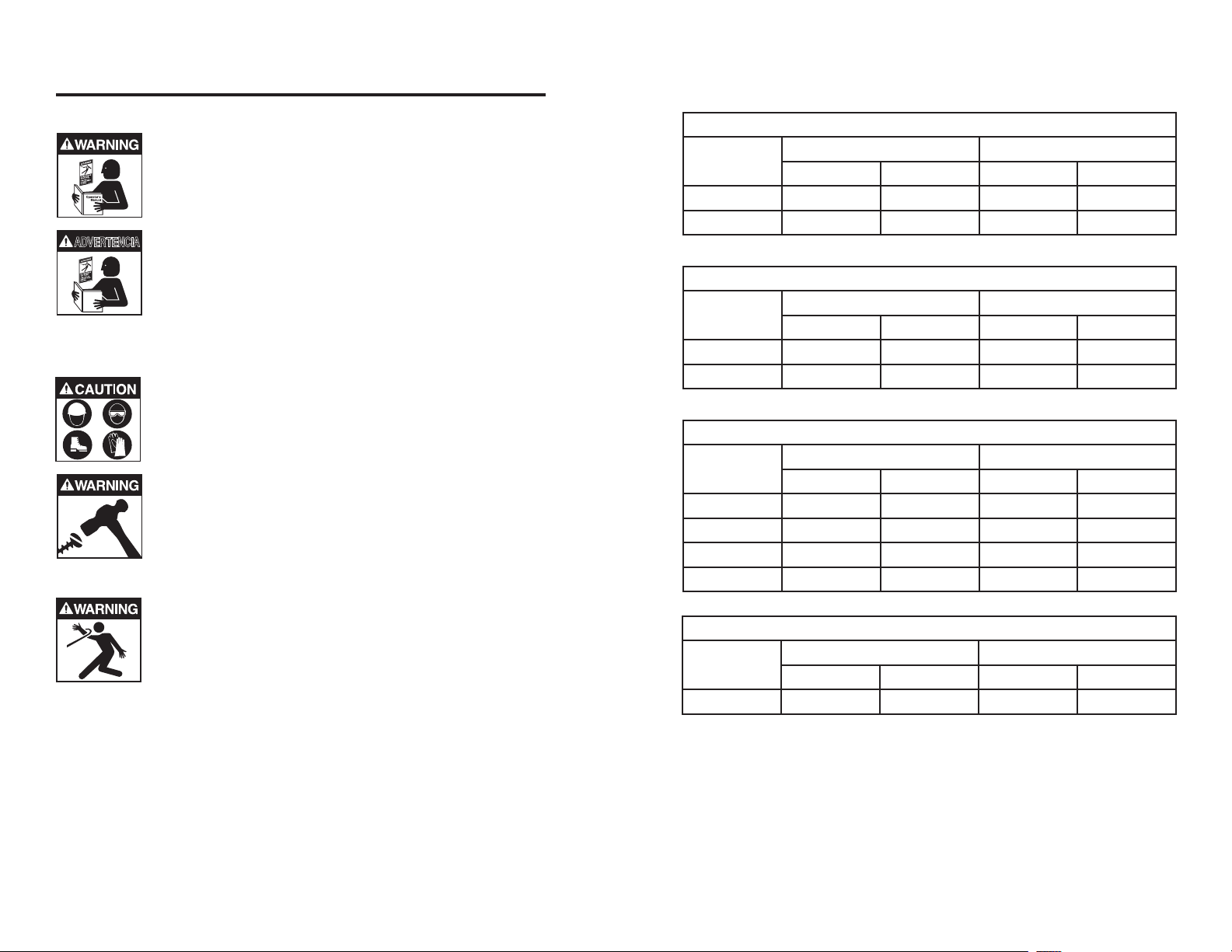
!WARNING: Read and understand all procedure
and safety instructions before using any Condux
product. Failure to do so may result in personal
injury or property damage. Save this user guide for
future reference.
!ADVERTE N C IA: Lea y ent i e nd a t o d os lo s
procedimientos e instrucciones de seguridad
antes de usar cualquier producto Condux. De lo
contrario, puede resultar en lesiones personales o
daños materiales. Guarde esta guía del usuario
para futuras consultas.
!CAUTION: Wear personal protective equipment:
hard hat, safety glasses, safety shoes, and leather
work gloves. Failure to do this could result in
personal injury.
!WARNING: The Break-Away D. Drill® Swivels are for
directional drilling only. Severe personal injury and
property damage could result if used with rope or
steel winch lines in cable pulling applications.
!WARNING: Do not exceed the load capacity of the
D. Drill® Swivel or any element in the pull string. Do
not stand directly behind the pull string. If any
component breaks, severe personal injury or
property damage could result.
2 (51mm) Break Away Swivels
Swivel
Part No
Break Load Replacement Pin
LBS N Part No Color
08029200 9000 40034 08029205 RED
08029400 10000 44482 08029405 GREEN
2 1/2 (64mm) Break Away Swivels
Swivel
Part No
Break Load Replacement Pin
LBS N Part No Color
08029600 12000 53379 08029605 WHITE
08029700 14000 62275 08029705 BROWN
3 (76mm) Break Away Swivels
Swivel
Part No
Break Load Replacement Pin
LBS N Part No Color
08075810 12000 53379 08075815 GREEN
08075600 18500 82292 08029720 BLACK
08075800 22000 97861 08075805 YELLOW
08075820 25000 111206 08075825 BLUE
4 (102mm) Break Away Swivels
Swivel
Part No
Break Load Replacement Pin
LBS N Part No Color
08075940 40000 177929 08075945 ORANGE
Table 2 Continued
112
Page 3

Inspection Procedure
1 1/4 (32mm) Break Away Swivels
Swivel
Part No
08021400 750 3336 08021405 ORANGE/VIOLET
08021500 1200 5338 08021505 BROWN/WHITE
08019400 1900 8452 08019405 VIOLET/BLACK
08019500 2000 8896 08019505 SLATE/WHITE
08019600 2500 11121 08019605 VIOLET/GREEN
08019700 3000 13345 08019705 SLATE/RED
08076100 3400 15124 08076105 BLUE/YELLOW
08019800 4000 17793 08019805 RED/YELLOW
Swivel
Part No
08019900 4500 20017 08019905 SLATE/YELLOW
08021300 5000 22241 08021305 ORANGE/BLUE
08022100 5500 24465 08022105 BROWN/GREEN
08024200 6000 26689 08024205 BLUE/BROWN
08024400 6500 28913 08024405 RED/BLUE
Swivel
Part No
08024500 7000 31138 08024505 ORANGE
08025500 7500 33362 08025505 BLUE
08027900 8000 35586 08027905 YELLOW
08028400 8500 37810 08028405 SLATE
Break Load Replacement Pin
LBS N Part No Color
1 3/8 (35mm) Break Away Swivels
Break Load Replacement Pin
LBS N Part No Color
1 5/8 (41mm) Break Away Swivels
Break Load Replacement Pin
LBS N Part No Color
Table 2 Continued
Inspecting the swivel before and after each use ensures proper
operation throughout the job.
1. Rotate the swivel to test for proper operation.
2. Wiggle the swivel’s end to ensure there is no lateral play.
3. Make sure the clevis pin (7⁄8" - 13⁄8" dia. swivels) or nuts and bolts
(15⁄8" - 4" dia. swivels) are not damaged and are the correct size and
grade for the swivel.
4. If necessary, lubricate the swivel (see Lubrication Procedure).
7
⁄8" & 15⁄8" - 4"
Lubrication Procedure
N OT E : A l w a y s u s e s p e c i a l C o nd u x D. D r i l l gr e a s e
(Co ndux p n: 081 9000 7). It i s s pec i all y fo rmu l ate d w ith a
calcium-complex soap for exclusive use in bentonite environments.
Use of lithium-based grease voids the warranty.
The Break-Away D. Drill® Swivel will fail if not
properly lubricated. Personal injury or property
damage could result.
1. Locate and clean the grease-zerk
fitting (Figure 1).
2. Inject grease through the zerk fitting
until the old grease flushes past the
seals on the swivel’s other end.
3. Lubricate after every job. This extends
the life of the swivel and prevents swivel lockup.
4. Hand pump grease for the 7/8" swivels. Do not use a high pressure
grease gun as this will void the warranty.
Figure 1. Grease-Zerk Fitting
for
dia. swivels only
Replacement Parts & Supplies
Condux offers replacement clevis pins, bolts, nuts and directional drilling
grease. Consult your Condux catalog, or see your Condux representative
for more information.
310
Page 4

Installation Procedure
NOTE: The D.Drill® Swivel has four angular contact bearings: three for
tension loads and one for compression loads. The direction of
installation is not critical, but on 7⁄8" & 15⁄8" - 4" dia. swivels we
recommend pointing the end with a grease zerk towards the reamer.
This helps prevent dirt from getting past the seals.
1. Ensure the swivel is the correct size for the job (see Table 1), and
test the swivel operation.
2. Connect the swivel between the pulling eye and the earth packer
or reamer.
3. Tighten the clevis pin (7⁄8" - 13⁄8" dia. swivels) or nuts and bolts
(15⁄8" - 4" dia. swivels) securely.
Removal is the opposite of the installation procedure.
Pulling Eye
Clevis Pin (
or Nuts & Bolts (1
Figure 2. Swivel Connection
7
⁄8" - 13⁄8")
5
⁄8" - 4")
Earth packer or reamer
7/8 (22mm) Break Away Swivels
Swivel
Part No
Break Load Replacement Pin
LBS N Part No Color
08021015 150 667 08018105 SLATE/VIOLET
08021020 200 890 08018305 GREEN/ORANGE
08021025 250 1112 08018005 BLUE/WHITE
08021030 300 1334 08017605 BROWN/RED
08021035 350 1557 08018405 BLACK/GREEN
08021040 400 1779 08075305 BLUE/BLACK
08021045 450 2002 08015805 BLUE/YELLOW
08021050 500 2224 08076505 ORANGE/RED
08021055 550 2447 08018505 BLUE/GREEN
08021060 600 2669 08015005 ORANGE/BLACK
08021065 650 2891 08018605 SLATE/GREEN
08021070 700 3114 08076005 ORANGE/WHITE
08021075 750 3336 08075505 ORANGE/VIOLET
08021080 800 3559 08018705 RED/YELLOW
08021085 850 3781 08018805 BLACK/YELLOW
08021090 900 4003 08076605 ORANGE/YELLOW
08021100 1000 4448 08015705 GREEN/WHITE
08021110 1100 4893 08018905 WHITE/YELLOW
08021120 1200 5338 08015205 BROWN/WHITE
08021130 1300 5783 08019105 BROWN/YELLOW
08021140 1400 6228 08074605 GREEN/RED
08021150 1500 6672 08076905 GREEN/YELLOW
08021160 1600 7117 08019205 BLACK/WHITE
08021170 1700 7562 08019305 RED/WHITE
08021180 1800 8007 08017705 BROWN/BLACK
Table 2
94
Page 5

9. Internally threaded head must turn freely after assembly.
10. Apply grease to bearings through grease zerk until the grease is
visible by the internally threaded head. Use Condux 08190007
D.Drill® Swivel grease or a non-lithium based equivalent.
11. Wipe excess grease off outside of swivel.
12. Install the clevis pins (11⁄4" & 13⁄8") or clevis bolts and nuts (15⁄8" - 4").
Diagram 1
EXTERNAL THREADED CLEVIS HEAD
INTERNAL THREADED CLEVIS HEAD
BEARINGS (3)
SEAL (1)
7
⁄8" - 13⁄8" Dia. Swivel
CLEVIS BOLT AND NUT
CENTER (BREAK) PIN
7
⁄8" - 13⁄8" Dia. Swivel
Diagram 2
EXTERNALLY THREADED HEAD
SETSCREW ROLL PINBODY
CENTER (BREAK) PIN
5
⁄8" - 4" Dia. Swivel
1
BODY
INTERNALLY THREADED HEAD
SEALS (2) (NOTE ORIENTATION)
BEARINGS (3) (NOTE ORIENTATION)
BEARING (1) (NOTE ORIENTATION)
5
⁄8" - 4" Dia. Swivel
1
Center Break
Pin
58
Page 6

Disassembly Procedure Assembly Procedure
1. Remove the clevis pins (11⁄4" & 13⁄8") or clevis bolts and nuts
(15⁄8" - 4") from the swivel.
2. Remove the setscrew from the side of the swivel (15⁄8" - 4").
3. Drive the roll pin out of the swivel (15⁄8" - 4"). Use a roll pin punch and
remove the pin completely.
4. Remove the broken pin’s shaft from the internally threaded head.
You may need to apply heat (use a propane torch) to the threads on
the break pin to loosen the Threadlocking Compound existing on the
threads.
5. Hold the body of the swivel securely in an appropriate vise. Hold the
swivel near the internally threaded head. Use soft jaws, a pipe vise
or a strap wrench if possible. Tighten the vise but do not over-tighten.
Overtightening of the vise may collapse the body and permanently
deform the swivel.
6. Remove the externally threaded head of the swivel. You may need to
ap p l y heat to the outside of the swivel to break down the
Threadlocking Compound existing on the threads.
7. Remove the bearings and seals from the swivel. Take note of the
bearing and seal orientation as they are removed to assure
proper replacement.
11⁄4" & 1
3
⁄8" Dia. Swivel
1. Clean I.D. of bearings, external and internal threads free of oil,
grease, old Threadlocking Compound and anti-seize compound and
replace any parts that are defective.
2. The bearings and seals must be assembled as shown in the
swivel drawing (see Diagram 1 or 2).
3. Slide the bearings onto the break pin’s shaft (see Table 2 for correct
replacement break pin). Do not force the bearings - it could damage
the pin.
4. Apply Threadlocking Primer to the threads of the center pin and to the
th reads on th e exte r nally thre a ded head. Ap p ly Removable
Threadlocking Compound to the same threads. Do not apply
Threadlocking Compound to clevis pin (11⁄4" & 13⁄8") or clevis bolt or
nut (15⁄8" - 4").
5. Insert the break pin and bearings into the swivel body. Screw the
break pin into the internally threaded head and tighten until snug. Do
not overtighten.
6. Torque break pin and externally threaded head to the following
specifications table (Table 1):
Swivel
Diameter
Break Pin External Threaded Head
Torque Value
1 1/4" 10-15 in-lbs 20-25 ft-lbs
1 3/8" 10-15 in-lbs 20-25 ft-lbs
1 5/8" 15-20 in-lbs 90-100 ft-lbs
2" - 4" 15-20 in-lbs 120-130 ft-lbs
Table 1
5
⁄8" - 4" Dia. Swivel
1
7. Using hole in swivel body, re-drill hole thru Center Break Pin. Press
Roll Pin thru Head and Center Break Pin until Roll Pin is centered in
5
Head (1
⁄8" - 4" swivels only).
8. Screw External Threaded Head back into the Body. Screw until snug
and then align Setscrew holes. Install Setscrew in Body and Head
(15⁄8" - 4" swivels only).
76
 Loading...