

Page 1

Mounting Instructions
Programm 0514
ProfiDAT® Data Transmission System
MAL0514-0005b-EN
www.conductix.com translated document page 1 of 82
Page 2

Mounting Instructions
Programm 0514
ProfiDAT® Data Transmission System
Contents
1 General Notes ............................................................................................................................................................................. 6
1.1 About this Document ................................................................................................................................................... 6
1.2 Limitation of Liability .................................................................................................................................................... 6
1.3 Copyright ..................................................................................................................................................................... 7
1.4 Spare Parts .................................................................................................................................................................. 7
1.5 Material defects ........................................................................................................................................................... 7
1.6 Technical support ........................................................................................................................................................ 7
2 Safety Instructions ...................................................................................................................................................................... 8
2.1 Explanation of Symbols ............................................................................................................................................... 8
2.2 Personnel Requirements ............................................................................................................................................. 9
2.2.1 Qualifications ............................................................................................................................................................... 9
2.2.2 Unauthorized Personnel .............................................................................................................................................. 9
2.2.3 Training ...................................................................................................................................................................... 10
2.3 Personal Protective Equipment ................................................................................................................................. 10
2.4 Intended Use ............................................................................................................................................................. 11
2.4.1 Improper use ............................................................................................................................................................. 11
2.5 Protective Measures to be taken by the Owner/Operator ......................................................................................... 12
2.6 Special Hazards ........................................................................................................................................................ 14
2.6.1 5 Protective Safety Rules when working on Electrical Systems ................................................................................ 14
2.6.2 Electrical Hazards and Sources of Danger ................................................................................................................ 15
2.6.3 Mechanical Hazards and Sources of Danger ............................................................................................................ 16
2.6.4 Danger due to Dust and Vapors ................................................................................................................................ 18
2.6.5 Danger related to the Place of Use ........................................................................................................................... 19
2.6.6 Unexpected Startup, unexpected Movement ............................................................................................................ 19
2.6.7 Emergency Stop ........................................................................................................................................................ 20
2.6.8 Hazard Areas ............................................................................................................................................................. 20
2.7 Safety Devices ........................................................................................................................................................... 21
2.8 Conduct in the Event of Accidents and Malfunctions ................................................................................................ 22
3 Technical Specifications ........................................................................................................................................................... 23
3.1 General Information ................................................................................................................................................... 23
MAL0514-0005b-EN
www.conductix.com translated document page 2 of 82
Page 3

Mounting Instructions
Programm 0514
ProfiDAT® Data Transmission System
3.2 Interfaces ................................................................................................................................................................... 23
3.2.1 Electrical .................................................................................................................................................................... 23
3.2.2 Mechanical ................................................................................................................................................................ 24
3.3 Technical Data for the Transceiver ............................................................................................................................ 25
3.4 Technical Data for HF Cables ................................................................................................................................... 25
3.5 Operating Conditions ................................................................................................................................................. 26
4 Product Description and Mode of Operation ............................................................................................................................. 27
4.1 Overview .................................................................................................................................................................... 27
4.2 Brief Description ........................................................................................................................................................ 27
4.3 Description of Assemblies ......................................................................................................................................... 28
4.3.1 ProfiDAT® System ..................................................................................................................................................... 28
4.3.2 Electrical Components ............................................................................................................................................... 30
4.4 Modes of Operation ................................................................................................................................................... 32
4.4.1 Normal Operation ...................................................................................................................................................... 32
5 Transport, Packaging and Storage ........................................................................................................................................... 33
5.1 Shipment ................................................................................................................................................................... 33
5.1.1 Safety Instructions for Transport ............................................................................................................................... 33
5.1.2 Transporting packaged Parts .................................................................................................................................... 33
5.1.3 Transport Inspection .................................................................................................................................................. 34
5.2 Packaging .................................................................................................................................................................. 34
5.3 Storage of packaged Parts ........................................................................................................................................ 35
6 Installation and Commissioning ................................................................................................................................................ 36
6.1 Safety ........................................................................................................................................................................ 36
6.2 Preparations .............................................................................................................................................................. 37
6.3 Grounding .................................................................................................................................................................. 38
6.3.1 TN Network ................................................................................................................................................................ 38
6.3.2 Grounding Implementation Instructions ..................................................................................................................... 38
6.4 Mechanical Installation .............................................................................................................................................. 39
6.4.1 Installation of the Expansion Element ....................................................................................................................... 39
6.4.2 Mounting the ProfiDAT® Profile ................................................................................................................................. 41
6.4.3 Installing the PE rail connector .................................................................................................................................. 43
MAL0514-0005b-EN
www.conductix.com translated document page 3 of 82
Page 4

Mounting Instructions
Programm 0514
ProfiDAT® Data Transmission System
6.4.4 Installing the rail connector (without PE) ................................................................................................................... 44
6.4.5 Installing the Anchor Point ......................................................................................................................................... 44
6.4.6 Installing the Entry Funnel ......................................................................................................................................... 47
6.4.7 Adjusting the length of the ProfiDAT® Profile ............................................................................................................ 47
6.4.8 Installing the Infeed ................................................................................................................................................... 49
6.4.9 Connecting the ProfiDAT® Profile to the Entry Funnel .............................................................................................. 50
6.4.10 Installing the Terminating Unit ................................................................................................................................... 51
6.4.11 Installing the Current Collector .................................................................................................................................. 52
6.4.12 Installing the PE Cable on the ProfiDAT® Profile ....................................................................................................... 54
6.4.13 Use of the ProfiDAT® profile without PE function ...................................................................................................... 55
6.4.14 Installing Trace Heating (optional) ............................................................................................................................. 55
6.4.15 Mounting a Temperature Sensor (optional) ............................................................................................................... 56
6.4.16 Retrofitting of a PE Rail Connector (Ground) ............................................................................................................ 56
6.5 Electrical Installation .................................................................................................................................................. 59
6.5.1 Installing the ProfiDAT® Infeed Switching Cabinet .................................................................................................... 60
6.5.2 Installing a ProfiDAT® Transceiver on a Mobile System Component ........................................................................ 61
6.5.3 Installing the Connecting Cable (HF cable) on the Infeed Antenna ........................................................................... 62
6.5.4 Installing the Connection Cable (HS Cable) on the Transceiver ............................................................................... 62
6.6 Profile-heating (optional) ........................................................................................................................................... 63
6.6.1 Profile-heating Controller ........................................................................................................................................... 64
6.6.2 Profile-heating Components ...................................................................................................................................... 65
6.7 Checklist and Initial Commissioning .......................................................................................................................... 66
7 Operation .................................................................................................................................................................................. 69
7.1 Safety ........................................................................................................................................................................ 69
8 Maintenance and Servicing ....................................................................................................................................................... 70
8.1 Safety ........................................................................................................................................................................ 70
8.2 Maintenance Plan ...................................................................................................................................................... 71
8.2.1 Documentation .......................................................................................................................................................... 72
8.2.2 Replacement of the ProfiDAT® Antenna .................................................................................................................... 72
8.2.3 Maximum Wear of the Carbon Brushes .................................................................................................................... 74
8.2.4 Replacement of Carbon Brushes on the ProfiDAT® Current Collector ...................................................................... 75
MAL0514-0005b-EN
www.conductix.com translated document page 4 of 82
Page 5

Mounting Instructions
Programm 0514
ProfiDAT® Data Transmission System
9 Troubleshooting ........................................................................................................................................................................ 78
10 Dismantling and Disposal ......................................................................................................................................................... 79
10.1 Safety ........................................................................................................................................................................ 79
10.2 Dismantling ................................................................................................................................................................ 79
10.2.1 Dismantling the Assembly ......................................................................................................................................... 79
10.3 Disposal ..................................................................................................................................................................... 80
11 Additional Documents ............................................................................................................................................................... 81
11.1 Conformity Declaration .............................................................................................................................................. 81
11.2 Other applicable Documents ..................................................................................................................................... 81
12 Index ......................................................................................................................................................................................... 82
MAL0514-0005b-EN
www.conductix.com translated document page 5 of 82
Page 6

Mounting Instructions
Programm 0514
ProfiDAT® Data Transmission System
1 General Notes
1.1 About this Document
This document facilitates safe and efficient working with the Conductix-Wampfler ProfiDAT® data-transmission system. The datatransmission system consists of components integrated into a conductor rail system by the system engineer for the transmission of
data between a base unit and a mobile system component.
This document is a part of the data transmission system, and must be kept in its immediate vicinity and accessible to personnel at
all times. Personnel must read this document carefully and understand it before starting any work. Compliance with all safety and
handling instructions given in this document is a basic prerequisite for safe working.
Local accident-protection regulations and general safety guidelines for the area of use of the data-transmission system also apply.
Illustrations in this document are provided for basic understanding and may deviate from the actual versions of individual components.
In addition to these instructions, the instructions in the appendices for the individual installed components also apply.
1.2 Limitation of Liability
All data and information in this mounting instructions have been compiled in compliance with the applicable standards and regulations, best practice and our many years of experience and knowledge.
The manufacturer accepts no liability for damages resulting from:
Failure to comply with this document
Improper use
Use by untrained personnel
Unauthorized modifications
Technical changes
Use of unauthorized replacement parts and accessories
The actual scope of delivery may differ from the explanations and descriptions provided here if the model in question is a spe-
cial one, if additional equipped has been ordered or due to recent technical changes.
The obligations agreed upon in the delivery agreement and our General Terms and Conditions of business apply, as do the delivery
conditions of the manufacturer and the legal regulations applicable at the time the contract was concluded.
All products are subject to technical modifications in the context of improvement of function and further development.
MAL0514-0005b-EN
www.conductix.com translated document page 6 of 82
Page 7
Mounting Instructions
Programm 0514
WARNING!
Incorrect spare parts are a safety hazard!
Incorrect or faulty spare parts can impair safety as well as resulting in damage, malfunctions
or complete failure.
Always use original spare parts from the manufacturer!
ProfiDAT® Data Transmission System
1.3 Copyright
This document is subject to copyright, and is exclusively intended for internal use by customers.
Provision of the mounting instruction to third parties, reproduction in any form — even in part — as well as the reuse and/or disclosure
of its content are not permitted without the written approval of the manufacturer, except for the customer's internal use.
Infringements will result in liability for damages. Our right to further claims remains unaffected.
1.4 Spare Parts
Order spare parts from your contracted dealer or directly from the manufacturer.
Contact details: See the last page of this document.
Spare parts: see Section 11.2
1.5 Material defects
The regulations about material defects are listed in the general terms and conditions of business.
1.6 Technical support
For technical support please contact our staff from the Customer Support Department.
Contact details: See the last page of this document.
Our employees are also always interested in new information and experience from the field that can be valuable for the improvement
of our products.
MAL0514-0005b-EN
www.conductix.com translated document page 7 of 82
Page 8
Mounting Instructions
Programm 0514
DANGER!
… indicates an immediately hazardous situation that will result in death or serious injury if not
avoided.
DANGER!
… indicates an immediately hazardous situation due to electricity that will result in death or se-
rious injury if not avoided.
WARNING!
… indicates a potentially hazardous situation that can result in death or serious injury if not
avoided.
WARNING!
… indicates a potentially hazardous situation due to electricity that can result in death or seri-
ous injury if not avoided.
CAUTION!
… indicates a potentially hazardous situation that can result in moderate or minor injury if not
avoided.
Tips and recommendations:
… highlights useful tips and information for efficient, problem-free operation.
CAUTION!
… indicates measures that will help you avoid material damage.
ProfiDAT® Data Transmission System
2 Safety Instructions
2.1 Explanation of Symbols
Safety and hazard information is identified by symbols in this mounting instruction. Safety instructions are introduced by signal words
that signal the scale of the hazard. Always observe safety and hazard instructions, and work carefully to avoid accidents, bodily injury
and damage to property!
MAL0514-0005b-EN
www.conductix.com translated document page 8 of 82
Page 9

Mounting Instructions
Programm 0514
WARNING!
Inadequately trained persons are at risk of injury!
Improper use can result in serious personal injury or material damage.
All activities must only be performed by qualified personnel.
WARNING!
Danger due to unauthorized personnel!
Unauthorized persons who do not meet the requirements described here are not acquainted
with the dangers in the working area.
Keep unauthorized personnel away from the working area.
In case of doubt, address the person and direct them away from the working area.
Stop working, as long as unauthorized persons are in the working area.
ProfiDAT® Data Transmission System
2.2 Personnel Requirements
2.2.1 Qualifications
Only persons who can be expected to perform their work reliably are acceptable personnel. People whose reactions are
impaired by drugs, alcohol or medications, for example, are not authorized.
When selecting personnel, follow all age- and occupation-specific guidelines applicable at the location of use.
The following qualifications are specified in the operating instructions for certain fields of activity.
Trained personnel and operators
have participated in a training session, given by the owner, on the tasks assigned to them and the potential hazards in case of
improper conduct.
The owner of the machine or system must document that the appropriate training has taken place.
Specialist personnel
consists of persons capable of performing assigned tasks and independently identifying and avoiding potential hazards based
on their specialist training, knowledge and experience as well as their knowledge of the applicable regulations.
Persons are deemed to be technically qualified if they have successfully completed training as a master electrician, apprentice
electrician, electrical engineer or electrical technician. Persons are also considered technically qualified if they have been employed in an appropriate capacity for several years, receiving theoretical and practical training in that time, and their
knowledge and skills have been tested by a specialist in the appropriate field of training.
The machine or system owner must document that the appropriate certificates or other proofs of qualification have been or are
being provided.
2.2.2 Unauthorized Personnel
MAL0514-0005b-EN
www.conductix.com translated document page 9 of 82
Page 10
Mounting Instructions
Programm 0514
Date
Name
Type of training
Training given by
Signature
11/5/2009
John Doe
First safety training for
personnel
Dave Miller
Always use:
For all tasks:
Safety helmet
For protection against falling or flying parts and materials.
Protective gloves
For the protection of hands against friction, scrapes, puncture or deeper wounds, as well as against
contact with hot surfaces.
Protective work clothing
Primarily for protection against entrapment by moving machine parts. Work clothing must be close fitting
with a low resistance to tearing; it must have close-fitting sleeves and no protruding parts.
Protective footwear
For protection against heavy falling parts and slipping on slippery floors.
Used for special
tasks:
Specific protective equipment is required when executing particular tasks. Separate reference to this is
made in the individual sections.
Safety eyewear
For eye protection against harmful influences such as strong light, chemicals, dust, splinters or weather
effects.
Hearing protection
For protection against loud noises and to prevent acoustic trauma.
Breathing mask (FFP-3 — according to country-specific requirements)
For protection against materials, particles, and organisms. In this case, for protection against the dust produced by the abrasion of carbon brushes and the PVC insulation of the conductor rail.
ProfiDAT® Data Transmission System
2.2.3 Training
Before commissioning the equipment, personnel must be trained by the owner. Log the implementation of training for better traceability.
Example of a training log:
2.3 Personal Protective Equipment
MAL0514-0005b-EN
www.conductix.com translated document page 10 of 82
Page 11

Mounting Instructions
Programm 0514
WARNING!
Hazard due to improper use!
Any application that deviates from or goes beyond the intended use of the devices can result
in hazardous situations.
Strict compliance with the specifications of this installation manual is required.
Refrain from improper use of the system.
Respect the instructions on improper use in chapter 2.4.1.
ProfiDAT® Data Transmission System
2.4 Intended Use
The data-transmission system is designed and built exclusively for the usage described here (intended use).
Intended use
The ProfiDAT® data-transmission system is used for data communication between a base unit and a mobile system component.
In addition to the capacity to transmit data, the ProfiDAT® profile can also be used as a ground conductor rail together with conductor
rails in product ranges 0813/0812 (max. 1000 V/max. 1000 A).
Transmission of electrical power is not permitted.
The system comprises at least one access point and one client transceiver, together with the corresponding infeed and consumer
antennas.
Compliance with these technical conditions is mandatory for the installation:
The maximum permitted traversing speed of the mobile transceiver is 5 m/s.
The profile may only be installed horizontally with the access aperture facing down.
Side access is also feasible after prior technical testing and approval by the manufacturer.
Electrical-engineering operating conditions:
The electrical system must be protected in accordance with local regulations and guidelines.
The system may only be installed on the PE profile (protective conductor, green/yellow).
2.4.1 Improper use
Claims of any kind due to damage incurred during use that deviates from the intended use described above ("use other than the
intended use") are excluded.
The owner bears sole liability for any damage resulting from improper use.
Improper use in particular includes the following forms of use:
Operation that does not comply with the specified operating conditions (see chapter 3.5)
Use of the ProfiDAT
Use where there is a risk of explosion (“Ex”-classified zones)
Use of the transceiver without the profile
Use of transceivers not supplied by Conductix-Wampfler
Use of the system parallel to a conductor rail system of a brand/type not approved by Conductix-Wampfler
Use of the system with accessories that are not approved and not authorized by the manufacturer
Use of the system by untrained personnel
MAL0514-0005b-EN
www.conductix.com translated document page 11 of 82
®
profile for the transmission of power
Page 12

Mounting Instructions
Programm 0514
ProfiDAT® Data Transmission System
Environmental conditions
The ProfiDAT® data transmission system may only be used under the ambient conditions described in chapter 3.
The ProfiDAT® data transmission system must not be used under the following ambient conditions:
Temperatures below -25°C or above +50°C
Wind speeds above 25 m/s (10 Bft) or 32.7 m/s (12 Bft) if the system is inactive.
Solar irradiance levels greater than 1120 W/m² (for components directly exposed to sunlight)
2.5 Protective Measures to be taken by the Owner/Operator
The data transmission system is used in an industrial setting. The owner of the data transmission system is therefore subject to the
legal obligations concerning workplace safety. In addition to the safety instructions in this document, all safety, accident-prevention
and environmental regulations that apply where the data transmission system is used must also be observed. In particular, pay
attention to the following:
Work on electrical components of the system may only be carried out when disconnected from the power supply.
The owner must become acquainted with the applicable occupational-safety regulations and perform a risk analysis to identify
additional hazards arising from the specific working conditions where the system is used. This knowledge must be
implemented in the form of operating instructions for the data transmission system.
For the entire time that the data transmission system is in use, the owner must check whether the operating instructions it has
produced correspond to the current regulatory situation and adjust them if necessary.
The owner must clearly regulate and define responsibilities for installation, operation, troubleshooting and maintenance.
The owner must ensure that all employees involved with the system have read and understood this installation manual. The
owner must also train the personnel at regular intervals and inform them of hazards.
The owner must provide personnel with the necessary protective equipment.
The owner must keep the keys for switching cabinets in a safe place. "Safe" means that only explicitly authorized personnel
may have access to the keys. The keys may only be issued to specialist personnel as described in chapter 2.2.1.
The owner must verify that the operating frequency of the data transmission system is permitted in the place of use.
MAL0514-0005b-EN
www.conductix.com translated document page 12 of 82
Page 13

Mounting Instructions
Programm 0514
EMC Directive 2014/30/EU, including
EMC Directive
EN 6100-6-2
Interference immunity in industrial areas
EN 61000-6-4
Interference emissions for industrial areas
EN 61000-3-2
Limit values for harmonic currents
EN 61000-3-3
Limitation of voltage changes, voltage fluctuations and flicker in public low-voltage power
supply networks for devices with a nominal current of 16 A per conductor that are not
subject to special connection requirements
EN 62311
Assessment of electrical and electronic equipment with respect to limiting exposure of
persons to electromagnetic fields (0 Hz – 300 GHz)
Radio Equipment Directive
2014/53/EC, including
Radio equipment
EN 301 489-1 V1.8.1
EN 301 489-17 V2.2.1
Protection requirements with regard to EMC
EN 300 328 V1.8.1
EN 301 893 V1.7.1
Use of the radio frequency spectrum
EN 300 440-1 V1.6.1
Air interface for radio equipment
2,4 – 2,4835 GHz; 5,15 – 6,35 GHz; 5,47 – 5,725 GHz
Low Voltage Directive 2014/35/EU,
including:
Low Voltage Directive
EN 60950-22
Information-technology equipment: Equipment to be installed outdoors
EN 60529
Protection classes due to housings (IP code)
ProfiDAT® Data Transmission System
The owner must observe the following standards, regulations and directives when operating the system:
The owner is also responsible for ensuring that the data transmission system is always in perfect working order. The following thus applies:
The operator must ensure that the service intervals described in this document are observed.
The owner must have all safety systems inspected for functionality and completeness on a regular basis (once yearly if
possible, but at least as often as required by applicable national regulations).
If components or the system have been modified, the safety systems must be re-inspected and adapted to the changed
circumstances such that the system is safe again.
MAL0514-0005b-EN
www.conductix.com translated document page 13 of 82
Page 14

Mounting Instructions
Programm 0514
ProfiDAT® Data Transmission System
2.6 Special Hazards
The following chapter lists residual risks determined on the basis of a risk assessment.
Follow the safety instructions and warnings in this installation manual to reduce health hazards and to avoid dangerous situa-
tions.
2.6.1 5 Protective Safety Rules when working on Electrical Systems
Work on electrical systems only when they are disconnected from the power supply. Follow the 5 safety rules (see DIN VDE
0150-100:2009-10/EN 50110-1:2004-11) before starting work:
1. disconnect the system from the power supply at the main switch,
2. secure the main switch against being switched on again,
3. verify disconnection from the power supply by measurements,
4. ground and short-circuit parts of the system to be worked on,
5. cover or block off adjacent energized parts.
Only electricians or personnel trained in electrical work may disconnect power or approve reconnection of power after work
carried out in the disconnected state!
MAL0514-0005b-EN
www.conductix.com translated document page 14 of 82
Page 15
Mounting Instructions
Programm 0514
Risk of death by
electrical shock!
Risk of injury from
falling or being thrown
across the room after an
electrical shock!
Burns due to arcing
caused by short circuit!
Contact with energized components can lead to death or severe injury by electrical shock. There is also a risk of injury from shock reactions, falling or being
thrown across the room as a result of an electrical shock.
Work on the following components is dangerous:
Main power supply
Electrically live components: Power feed, cables, connections, conductor rail,
connectors, current collectors, devices and connections within switching
cabinets, control systems, etc.
Parts that have become live due to a fault
Before working on the parts listed above:
Switch off the powers supply of the conductor rail system according
to the 5 safety rules and secure it against being switched on again.
For the 5 safety rules, see Section 2.6.1.
During work:
Use insulated tools
Before switching on:
Every time before the system is started, test the insulation resistance
according to locally applicable technical standards, directives and legal
regulations.
Carry out locally required electrical tests.
Maintain electrical safety:
Regularly test and maintain electrical equipment.
If dangerous deficiencies are identified, take measures to correct the
deficiencies without delay. Inform the system operator immediately.
If it is not possible to correct the dangerous deficiency, block off the
area involved or turn the equipment off and secure it against being
switched on again. Inform the system operator immediately.
Immediately secure loose cables and replace damaged cables.
Always replace blown fuses with fuses of the same rating.
DANGER!
Fire hazard due to overload or sparking!
Fire hazards occur due to overloaded cables, electrical arcs, short circuits or sparking. Sparking
can occur in poorly serviced, contaminated conductor rails or if installation does not comply with
the required tolerances.
Compliance with permissible current ratings is mandatory.
Tolerances must be observed during installation.
Install electrical protection as prescribed.
Check, service, and clean conductor rails regularly and as prescribed. See the
information in the documents for conductor rail range 0812/0813.
ProfiDAT® Data Transmission System
2.6.2 Electrical Hazards and Sources of Danger
MAL0514-0005b-EN
www.conductix.com translated document page 15 of 82
Page 16

Mounting Instructions
Programm 0514
Risk of crushing injury!
Risk of impact injury!
There is a risk of crushing of skin and limbs due to:
Current collectors (spring force) during installation, dismantling and
maintenance
Falling parts of the data transmission system in case of improper installation or
unsuitable operating conditions (in solvent-containing environments, for
example)
Moving parts (current collectors, mobile equipment) when the system is in op-
eration
Do not enter the hazardous area of the system when in operation, except
for repair and maintenance tasks.
Have installation done only by trained technicians.
Wear safety footwear, protective gloves and a safety helmet when
working on the data transmission system.
When replacing the carbon brushes, follow the instructions in chapter
8.2.4.
Only install the system where suitable operating conditions prevail. See
chapter 3.5
Risk of injury when
cutting and trimming!
The ends of profiles and connectors can have sharp edges, especially if they have
been trimmed at the construction site and have not been deburred.
Use protective gloves and safety footwear.
During installation: Deburr insulating profiles and power rails after sawing.
When dismantling: Handle cut, removed profiles with care and store them
properly (transport or other container).
Be on the lookout for sharp edges near the installation area and avoid
contact.
Danger of injury by
falling objects!
ProfiDAT® profiles, current collectors and other components (e.g., antennas) can
fall off during operation or during any other work on the system. This can cause
severe injuries or fatalities if they fall from great heights.
Wear a safety helmet.
During installation, commissioning, troubleshooting, maintenance: Block
off the entire danger zone.
During decommissioning, dismantling, disposal: Block off the entire
danger zone. Handle cut, removed profiles with care and store them
properly (transport or other container).
ProfiDAT® Data Transmission System
2.6.3 Mechanical Hazards and Sources of Danger
MAL0514-0005b-EN
www.conductix.com translated document page 16 of 82
Page 17

Mounting Instructions
Programm 0514
Danger of injury by
catching and
entanglement!
There is a danger of being entangled in moving parts when the system is in
operation during installation, commissioning, or service. Moving parts include, for
instance, the crane and the current collectors attached to it.
Do not enter the hazardous area of the system when in operation, except
for repair and maintenance tasks.
Traverse at reduced speed!
Before working on the system, switch off the power supply of the
system according to the 5 safety rules and secure it against being
switched on again. For the 5 safety rules, see chapter 2.6.1.
Wear closely fitting work clothing.
ProfiDAT® Data Transmission System
MAL0514-0005b-EN
www.conductix.com translated document page 17 of 82
Page 18

Mounting Instructions
Programm 0514
Danger of sensitization,
irritation of the mucous
membranes, and
respiratory diseases due
to dust!
Abrasion debris from the carbon brushes collects in the ProfiDAT® profiles and the
guide profile. This dust is very fine and is classified as harmful to health. Frequent
exposure can lead to sensitization. Persons who frequently spend longer periods
in a heavily used system without protective equipment must reckon with the following consequences:
Irritations of the mucous membranes
Respiratory diseases
Cancer
These consequences must also be reckoned with if there is a lack of caution in
handling accumulated dust (by blowing out the dust with compressed air, for example).
In workplaces with long-term exposure and heavily use systems, take
effective measures to protect employees from the dust.
Use personal protective equipment during all work performed on the data
transmission system where accumulated dust can be stirred up. Use
personal protective equipment particularly when cleaning the system.
Safety eyewear
Dust mask, class FFP3
Gloves
Disposable coverall
Clean the profiles as prescribed before starting work. There are special
instructions for this task; see chapter 11.
During cleaning operations, protect the surrounding area, for example by
covering or removing stored materials and blocking off areas in which
dust could fall onto people.
Do not blow out dust with compressed air. Instead, vacuum it up. The
vacuum cleaner must be equipped with a Class H fine filter.
Do not eat, do not drink, do not smoke during the work!
Poisonous gases in case
of fire!
In the case of a fire in the system, the plastic parts of the conductor rail system (PVC) will emit
toxic gases (HCl).
Leave the system immediately.
Notify the fire brigade.
ProfiDAT® Data Transmission System
2.6.4 Danger due to Dust and Vapors
MAL0514-0005b-EN
www.conductix.com translated document page 18 of 82
Page 19

Mounting Instructions
Programm 0514
Danger by slipping and
falling!
When entering the system, there is a danger of slipping and falling due to
environmental conditions such as moisture, snow, water, contamination and wind.
Wear personal protective equipment when entering the system and during
all work on the ProfiDAT® system.
Suspend work on the ProfiDAT
®
system in strong wind: Risk of falling!
Clean severely contaminated system parts before entering.
Failure/fault of the control system, software error!
Failure of the data transmission system or a software error can result in unexpected system
movements.
A plausibility check of signals must be carried out by the customer's higher-level control
system. We recommend the use of PROFIsafe controllers.
Complete the start-up checklist, see chapter 6.6
Restore the energy feed
after failure of the power
feed!
Failure of the power feed can lead to uncontrolled movements of the system.
Initialization of the RAM memory (carried out automatically).
External influences on
electrical equipment due
to external sources of interference!
External sources of interference, such as radio or radar, can cause malfunctions of the
components and the WiFi network.
Use only shielded aluminum profiles made by the manufacturer.
A plausibility check of signals must be carried out by the customer's higher-level control
system.
ProfiDAT® Data Transmission System
2.6.5 Danger related to the Place of Use
The following characteristics of the ProfiDAT® system can cause hazards when the ProfiDAT® system is installed in its
operational environment:
Electrical energy
Sparking
Dust caused by abrasion (of the carbon brushes)
Material composition of the insulating profiles, which releases toxic vapors if burned
The most important measure to provide protection from these dangers is to install the ProfiDAT® system only in locations where
suitable operating conditions prevail. See chapter 3.5
2.6.6 Unexpected Startup, unexpected Movement
MAL0514-0005b-EN
www.conductix.com translated document page 19 of 82
Page 20
Mounting Instructions
Programm 0514
WARNING!
Risk of injury due to moving components!
When the system is operating, severe injuries can result if persons or objects are within the
movement range (hazard area!).
Do not start the system if there are persons or objects within the movement range
(hazard area!).
Exception: Repair and maintenance work. Traversing is only permitted at
reduced speed.
Make sure that the system cannot start up in an uncontrolled manner.
Do not reach into moving parts.
Block off the hazard area around the entire system.
WARNING!
Risk of injury due to moving components!
Serious injuries may occur if the system is moved in an uncontrolled manner.
Block off working and hazard areas.
Do not reach into moving parts. The interfaces between current collectors and rail-
fastening equipment are particularly dangerous.
CAUTION!
Crushing hazard due to stored energy!
When working on the current collector, there is the risk of crushing extremities due to
uncontrolled movements as a result of the energy stored in the spring.
The spring force must be taken into consideration, during all works on the current
collector. Do not reach between profiles and current collectors (see Fig. 1).
During installation, maintenance and repair works: Check the spring force with
caution.
ProfiDAT® Data Transmission System
2.6.7 Emergency Stop
The ProfiDAT® data transmission system is used for transparent transmission of safety-relevant signals. These signals must be
generated by a higher-level component. Suitable safety components must be used to guarantee the emergency-stop function. The
emergency stop must be implemented using safety equipment provided by the customer and depends on the nature of the power
supply.
We recommend the use of a PROFIsafe system.
2.6.8 Hazard Areas
MAL0514-0005b-EN
www.conductix.com translated document page 20 of 82
Page 21
Mounting Instructions
Programm 0514
Fig. 1: Sketch of the hazard area at the current collector
WARNING!
Risk of death due to inoperative safety devices!
Safety is only guaranteed if the safety devices are intact.
Before starting work, check that the safety systems are serviceable and properly
installed.
Never disable or deactivate safety systems.
Danger area
ProfiDAT® Data Transmission System
2.7 Safety Devices
The data transmission system has no safety devices. The system is always operated in conjunction with the plant in which the data
transmission system is installed. Therefore pay attention to the safety equipment of the plant!
MAL0514-0005b-EN
www.conductix.com translated document page 21 of 82
Page 22

Mounting Instructions
Programm 0514
Conductix-Wampfler GmbH
Rheinstrasse 27 + 33
79576 Weil am Rhein – Märkt
Germany
Phone: +49 (0) 7621 662-0
Fax: +49 (0) 7621 662-144
info.de@conductix.com
www.conductix.com
ProfiDAT® Data Transmission System
2.8 Conduct in the Event of Accidents and Malfunctions
Measures to take in the event of accidents:
Shut down the system and secure it against unauthorized, unintentional and/or erroneous activation.
Secure the danger zone
Remove persons from the danger zone.
Initiate first-aid measures
Alert the rescue services
Inform responsible parties at the operating site
Clear access routes for emergency vehicles
Measures to take in the event of malfunction:
Shut down the system and secure it against unauthorized, unintentional and/or erroneous reactivation.
Secure the work area against entry
Consult qualified personnel when analyzing the fault
Involve authorized personnel for maintenance and repair
Check for disconnection from power
Remove the component and replace with a new component
Determine the cause of the fault and repair the component
Conductix-Wampfler must be informed immediately if personal injury or material damage can occur during breakdowns.
MAL0514-0005b-EN
www.conductix.com translated document page 22 of 82
Page 23

Mounting Instructions
Programm 0514
Designation
Value, unit
System length (without segmentation)
500 m
Profile length
5000 mm
External profile dimensions (width x height)
50 mm x 56 mm
Power supply:
ProfiDAT® transceiver
ProfiDAT® infeed cabinet
24 V DC*
120–500 V AC / 50–60 Hz
Maximum data transmission rate
100 Mbit/s
Maximum travel speed of the mobile transceiver
(connection trolley)
5 m/s
Interface
Ethernet (RJ45 as standard)
System service life (except wear parts and
electrical components)
10 years
ProfiDAT® Data Transmission System
3 Technical Specifications
3.1 General Information
* Deviations may occur, see the manufacturer’s documentation (chapter 11.2 “Other applicable Documents”)
3.2 Interfaces
3.2.1 Electrical
The interfaces to the customer system are:
Data interface
Power supply/control voltage
PE
Data interface: ProfiDAT Ethernet, RJ45 connection.
The customer has to connect the ProfiDAT® system with its own system at both ends of the ProfiDAT® system with a RJ45 connector
or an optional LC (fiber-optic) connector. The interface is located on both the mobile and the stationary transceivers.
The customer system must provide the data using the Ethernet protocol. If the customer control system is not Ethernet capable, the
appropriate conversions must be made.
PE interface:
The interface for the customer's grounding cable is located at the PE rail connector (see chapter 4.3.1). At the flap (M10 drilled hole),
the PE cable must be connected according to the applicable standards.
MAL0514-0005b-EN
www.conductix.com translated document page 23 of 82
Page 24
Mounting Instructions
Programm 0514
Description
Voltage/frequency
AC power supply
Infeed switching cabinet
120–500 V, 50/60 Hz
DC control voltage
Transceiver
24 V DC*
WARNING!
Danger of injury by current collector!
Failure to comply with the prescribed supply voltages for the controller can cause a controller
failure and electrical components may be destroyed. As a result, the current collector may run
jerkily and hit persons or objects.
Observe and comply with the prescribed supply voltages.
Keep persons and objects out of the hazard area (see chapter 2.6.6).
ProfiDAT® Data Transmission System
Power supply/control voltage:
The controller of the ProfiDAT® data transmission system requires the following power supply:
* Deviations may occur, see the manufacturer’s documentation (chapter 11.2 “Other applicable Documents”)
On commissioning of the transceiver devices, please observe that the cycle periods for the ProfiDAT® communication distances must
be adapted.
The cycle period must be at least 32 ms (but can differ depending on the application) and must be adjusted accordingly in the superior
control assembly group.
3.2.2 Mechanical
The interface between the data transmission system and the system is:
Current collector
The current collector on the ProfiDAT® profile performs a dual function. Two divided carbon brushes guide the current collector on
the ProfiDAT® profile. The carbon brushes secure the connection to the ground conductor rail (ProfiDAT® profile) while data
transmission occurs via the two built-in antennas. The antennas are inserted into the slot in the ProfiDAT® profile and are electrically
isolated from the carbon brushes.
MAL0514-0005b-EN
www.conductix.com translated document page 24 of 82
Page 25

Mounting Instructions
Programm 0514
Designation
Value, unit
Ethernet
1 x 100 Mbit/s RJ45*
Supply voltage:
24 V DC*
Data rate
up to 100 Mbit/sec
Operating frequency
4.9–5.8 GHz**
Energy consumption
See the data sheet for the transceiver
Temperature range
See the data sheet for the transceiver
Dimensions (width x height x depth)
See the data sheet for the transceiver
Weight
See the data sheet for the transceiver
Designation
Value, unit
Temperature range
-25°C to +50°C
Min. bending radius
40 mm
Tension force
50 N
Recommended coupling torques:
N connector
SMA/R-SMA
4–6 Nm
79–113 Ncm
CAUTION!
The HF cables may not be squeezed (for instance through firm pulling at the cable binder).
Observe the bending radius of the HF cables.
Maintain the recommended coupling torque.
ProfiDAT® Data Transmission System
3.3 Technical Data for the Transceiver
* Deviations may occur, see the manufacturer’s documentation (chapter 11.2 “Other applicable Documents”)
** Country-specific deviations may occur
Please note the information in the documentation of the transceiver, see chapter 11.2. “Other applicable documents”.
3.4 Technical Data for HF Cables
The following values must not be exceeded:
MAL0514-0005b-EN
www.conductix.com translated document page 25 of 82
Page 26

Mounting Instructions
Programm 0514
Designation
Value
Notes
Minimum
Maximum
Conditions
Ambient temperature
-25°C
+50 °C
At a relative humidity of
[100% at +20°C]
Wind speed in operation
25 m/sec (10 Bft)
Wind speed when not in operation
32.7 m/sec (12
Bft)
CAUTION!
Faults due to incorrect operating conditions!
Operating conditions outside the specified range can lead to malfunctions due to short circuits,
premature aging, and damage to electrical and mechanical components.
Important parameters are:
Dust and deposits
Humidity/condensation
Cold/hot temperatures
Corrosion
ProfiDAT® Data Transmission System
3.5 Operating Conditions
MAL0514-0005b-EN
www.conductix.com translated document page 26 of 82
Page 27

Mounting Instructions
Programm 0514
Fig. 2: Overview
ProfiDAT® Data Transmission System
4 Product Description and Mode of Operation
4.1 Overview
4.2 Brief Description
The ProfiDAT® data transmission system provides a means of communication between the base station and the mobile system
component. The ProfiDAT® system is installed parallel to the electrification system.
In addition to data transmission, the ProfiDAT® profile can simultaneously be used as a ground conductor rail. The system has a
variable length. It consists of at least one fixed and one mobile transceiver, the infeed antenna and the consumer antenna. Hanger
clamps are used to fasten the profiles to the steel construction, which is provided by the customer. The profiles are mechanically
attached using connectors that ensure the stability and secure connection of the profiles. Data is fed into and received from the
profile by means of an infeed antenna attached at the end of the system (end infeed) or within the system (central infeed/section
infeed). The mobile consumer antenna can continuously receive and transmit data.
Examples of applications are:
High-performance crane systems
Rope-drawn STS crane-trolley systems
People movers/passenger transportation systems
Portable electrical consumers
MAL0514-0005b-EN
www.conductix.com translated document page 27 of 82
Page 28

Mounting Instructions
Programm 0514
Fig. 3: Profile
Profile (slotted wave guide)
The profiles are used as a data channel. They are electrically conductive
and are simultaneously used as a protective conductor (PE).
The standard length of a profile is 5000 mm. The outer dimensions are
50 x 56 mm (width x height). The conductor cross-section is at least
585 mm².
Fig. 4: Hanger clamp
Hanger clamp
The rail clamps are attached to the supporting construction with nuts and
bolts, which are provided by the customer.
The hanger clamps are pushed onto the profiles. Two hanger clamps are
installed for each profile. The spacing between hanger clamps is
2500 mm.
Fig. 5: Hanger clamp for installation on a C-rail
Hanger clamp for installation on a 40 x 40-mm C-rail
Fig. 6: Anchor point
Anchor point
The anchor point is fixed to the hanger clamp and the PE rail connector
and is used to create a fixed point.
Fig. 7: Rail connector
Fig. 8: PE rail connector
Rail connector
The rail connector connects two profiles together and is screwed onto
the profile.
There are two types of connectors:
Connector, simple
PE connector, with connection for a grounding cable
The ground cable is attached to the lug (PE rail connector).
There must be a PE connector every five profiles (every 25 m) and at
each expansion element.
ProfiDAT® Data Transmission System
4.3 Description of Assemblies
4.3.1 ProfiDAT
®
System
MAL0514-0005b-EN
www.conductix.com translated document page 28 of 82
Page 29

Mounting Instructions
Programm 0514
Fig. 9: Infeed antenna
Fig. 10: Infeed antenna for funnel
Infeed antenna (infeed unit) with cable
The feed-in antenna is installed at the end of the system (end infeed). It
is used to feed data signals in and out.
System lengths up to 250 m are possible with end infeed.
There are two types of antennas:
Antenna screwed to the profile
Antenna for funnels, attached to the profile with a connector
At the end of the ProfiDAT® section, there is a terminating element with a
terminating resistance that attenuates the signal to the point that no
interference emissions are produced for other equipment in the vicinity of
the data transmission system.
Fig. 11: Expansion element
Expansion element
The expansion element connects two ProfiDAT® profiles together,
compensating for changes in the length of profiles due to temperature
fluctuations.
The expansion element is fastened to the ProfiDAT® profile using PE rail
connectors as well as by screws to the load-bearing profile. A flexible
cable transmits the data signal between the two antennas.
The expansion element can also be used as a section infeed. This allows system lengths of 500 m to be achieved. Segmentation makes the
system expandable (see chapter 6.4.8.2).
Fig. 12: Entry funnel
Entry funnel
The entry funnel is installed at the drive-in zone. The entry funnel guides
the current collector onto the conductor rail.
The entry funnel can only be used in systems with the slot facing down.
ProfiDAT® Data Transmission System
MAL0514-0005b-EN
www.conductix.com translated document page 29 of 82
Page 30

Mounting Instructions
Programm 0514
Fig. 13: Current collector (dual collector)
Fig. 14: Current collector (single collector)
Current collector
Two divided carbon brushes guide the current collector on the ProfiDAT® profile. The antennas are inserted into the slot in the ProfiDAT®
profile and are electrically isolated from the carbon brushes.
Use of the single collector:
If there are no transitions in the traversing range
If there are no expansion joints in the system
With end infeed
Fig. 15: Overview and arrangement of the electrical components
1
ProfiDAT® adapter cable
10
ProfiDAT® transceiver with 24 V power supply line
2
Infeed connection
11
R-SMA plug, terminating resistor 50 Ohm / 6 GHz / 1 W
3
Antenna adapter cable
12
N-connector terminating resistor, 50 Ohm / 6 GHz / 1 W
4
Antenna connection
A
Infeed switching cabinet
B
Current collector
C
Moving system part
D
ProfiDAT® profile
E
Expansion element (optional, depending on system type)
ProfiDAT® Data Transmission System
4.3.2 Electrical Components
MAL0514-0005b-EN
www.conductix.com translated document page 30 of 82
Page 31

Mounting Instructions
Programm 0514
© Siemens AG 2017. All rights reserved
Fig. 16: Transceiver (sample photo)
The transceiver is a PROFINET/PROFIsafe-compatible communication device
based on the IEEE 802.11n standard. Communication with PROFINET-IO uses
a Layer 2 Tunneling Protocol (L2TP).
Installation can be on a wall, profile, or DIN rail.
The figure shows an example, because various transceiver types are available.
See the manufacturer’s documentation for a detailed description of the
transceiver (chapter 11.2 “Other applicable Documents”).
Fig. 17: Infeed switching cabinet
The power feed cabinet contains the component needed to mount a ProfiDAT®
transceiver on the system. From the switching cabinet, the antenna connection
of the ProfiDAT® transceiver is connected to the infeed antenna on the
ProfiDAT® profile.
The ProfiDAT® transceiver is mounted on the DIN rail.
The infeed cabinet contains:
1) Transceiver (access point)
2) Thermostat/hygrostat
3) DIN rail (35 x 15 mm)
4) LED display/indicator light (optional)
5) Heating element (mounted in the side wall)
6) Connector terminals
7) Line circuit breaker
8) Power supply
Dimensions: 380 x 600 x 210 mm (width x height x depth)
ProfiDAT® Data Transmission System
Transceiver
ProfiDAT® power feed cabinet
Connectors:
Power supply (screw connection): 120–500 V AC / 50–60 Hz
Ethernet cable (screw connection):
N connector
Ground cable
MAL0514-0005b-EN
www.conductix.com translated document page 31 of 82
Page 32

Mounting Instructions
Programm 0514
“24V OK” indicator lamp
(in the door):
Lit: ProfiDAT® transceiver power supply is active.
ProfiDAT® Data Transmission System
Display:
HF cables
HF cables are used for connector cables and adapter cables for the transmission of data between the transceiver and antennas (see
Fig. 15).
4.4 Modes of Operation
The ProfiDAT® data transmission system is used in the “normal operation” mode.
4.4.1 Normal Operation
During normal operation, the operator controls the system. No person may be present in the working area during normal operation
to monitor the working process. Traversing commands are given exclusively by the operator.
MAL0514-0005b-EN
www.conductix.com translated document page 32 of 82
Page 33

Mounting Instructions
Programm 0514
WARNING!
Risk of death due to suspended loads!
When lifting loads, there is a risk of death from falling parts or parts swinging out of control.
Never walk under suspended loads.
Follow the specifications provided for the attachment points.
Do not lash to protruding machine parts or eyelets on attached components. Be sure
the lashing elements are firmly seated.
Use only authorized lifting gear and lashing components with sufficient load capacity.
Do not use torn or worn ropes or straps.
Do not attach ropes or straps at sharp corners and edges, and do not knot or twist
them.
Damage due to improper
transport!
Damage due to improper transport!
Improper transport can result in substantial property damage.
Unload packaged parts upon delivery and during internal transport with care, and ob-
serve the symbols and the hazard information on the packaging.
Use only the provided lashing points.
Wait until just before installation, for removing packaging material.
ProfiDAT® Data Transmission System
5 Transport, Packaging and Storage
5.1 Shipment
5.1.1 Safety Instructions for Transport
5.1.2 Transporting packaged Parts
Transport packed parts under the following conditions:
Dry and free of dust.
Do not expose to aggressive media.
Protect from direct sunlight.
Avoid mechanical vibrations.
Transport temperature: -25 to +50 °C.
Relative humidity max. 60 %
MAL0514-0005b-EN
www.conductix.com translated document page 33 of 82
Page 34

Mounting Instructions
Programm 0514
CAUTION!
File a complaint on every defect, as soon as it is detected. Damage compensation claims may
only be made within the applicable claim periods.
WARNING!
Environmental damage due to improper disposal!
Packaging materials are valuable resources and can often be reused or usefully processed
or recycled.
Dispose of packaging materials in an environmentally appropriate manner.
Comply with locally applicable disposal guidelines; if necessary, engage a specialist
company to handle the disposal.
ProfiDAT® Data Transmission System
5.1.3 Transport Inspection
Check the delivery for completeness and transport damage immediately upon receipt.
If transport damage is externally visible, proceed as follows:
Do not accept delivery, or accept it only with reservations.
Note the scope of damage on the transport documents or on the transporter's delivery note.
Submit a complaint.
5.2 Packaging
The individually packaged parts are packed in accordance with the anticipated transport conditions. Only environmentally friendly
materials have been used for packaging.
The packaging is designed to protect the individual components from transport damage, corrosion and other damage until installation.
As a result, do not destroy the packaging and remove it only shortly before installation.
Handling packaging materials:
Dispose of packaging material according to valid legal regulations and local guidelines.
MAL0514-0005b-EN
www.conductix.com translated document page 34 of 82
Page 35

Mounting Instructions
Programm 0514
CAUTION!
In some cases, there may be instructions for storage on the packed parts that go beyond the
requirements listed here. Comply with them accordingly.
ProfiDAT® Data Transmission System
5.3 Storage of packaged Parts
Store packaged parts under the following conditions:
Do not store outdoors.
Store in a dry, dust-free place.
Do not expose to aggressive media.
Protect from direct sunlight.
Avoid mechanical vibrations.
Storage temperature: 15 to 35 °C
Relative humidity: max. 60%
When storing for more than 3 months, check the general condition of all parts and the packaging at regular intervals. If
necessary, refresh or replace the preservative
MAL0514-0005b-EN
www.conductix.com translated document page 35 of 82
Page 36

Mounting Instructions
Programm 0514
WARNING!
Risk of death due to suspended loads!
Falling loads can cause serious injuries or even death.
Never walk under suspended loads.
Only move loads under supervision.
Set down the load before leaving the workplace
Injury due to improper installation and initial commissioning!
Improper installation and commissioning can result in serious personal injury and/or material
damage.
Before starting work, ensure sufficient space for assembly.
Handle open, sharp-edged components with care.
Make sure the installation area is tidy and clean! Loosely stacked or scattered
components and tools are sources of hazards.
Install components properly. Comply with specified screw tightening torques.
ProfiDAT® Data Transmission System
6 Installation and Commissioning
6.1 Safety
Personnel:
Installation and commissioning may only be carried out by specially trained technicians!
Use the following personal protective equipment for all installation and commissioning work:
Protective work clothing
Safety helmet
Protective footwear
Protective gloves
MAL0514-0005b-EN
www.conductix.com translated document page 36 of 82
Page 37

Mounting Instructions
Programm 0514
ProfiDAT® Data Transmission System
6.2 Preparations
Required tools:
Open-ended spanner, SW10
Open-ended spanner, SW17
Open-ended spanner, SW24
Set of Allen keys, SW3
Allen key, SW5
Phillips screwdriver
Torque wrench
Lubricant
Hot air blower
Chop saw
Required material:
Cable ties
Shrink sleeve
Conductive paste 080021
Lubricant for stainless-steel screws, recommended: Klüber 46 MR 401 paste
Klüber Lubrication München KG
Geisenhausenerstr. 7
D-81379 Munich
Screw tightening torques:
M6 screw (SW10 open-ended spanner): 8 Nm
M10 screw (SW17 open-ended spanner): 40 Nm
MAL0514-0005b-EN
www.conductix.com translated document page 37 of 82
Page 38

Mounting Instructions
Programm 0514
DANGER!
Risk of death by electrical shock!
The steel structure may be at high voltage if it is not properly grounded.
Contact with the steel structure can lead to death or severe injury. There is also a high risk of
injury from overreaction caused by electrical shock.
Read and follow the locally applicable and international guidelines for proper ground
installation and lightning protection.
Provide the grounding installation that is appropriate to the architecture of the power
grid at the place of installation of the system (TT network or TN network).
Connect the steel structure to the grounding installation.
Install a conductive connection between all parts of the steel structure. Use toothed
washers for screw connections or other suitable components to establish a conductive
connection between coated components
Regularly check the proper grounding of the steel structure.
ProfiDAT® Data Transmission System
6.3 Grounding
The system operator must ensure sufficient grounding of the steel structure, especially the painted components. Safety regulations
and country-specific directives for the grounding of electrical equipment (e.g. VDE/UVV/VBG4) must be followed.
The grounding of the steel structure must be taken into consideration for different application cases:
Protection against electrical shock
Lightning protection
6.3.1 TN Network
In a TN network, the ProfiDAT
power supply transformer.
The total impedance between phase conductor and PE conductor must not exceed 0.16 Ω.
®
profile (ground conductor rail) is connected by a cable directly to the grounded star point of the
6.3.2 Grounding Implementation Instructions
The ProfiDAT
every fifth conductor rail joint. The cross-section of the connector cable must be at least 16 mm².
Locally applicable standards or regulations may require different (lower) grounding impedance values. The system operator
must check the locally applicable standards or regulations and implement the grounding system accordingly.
The grounding impedance must be measured during installation and a test report prepared with the following content:
MAL0514-0005b-EN
www.conductix.com translated document page 38 of 82
Condition of the grounding unit,
Extent of corrosion and corrosion protection,
Fastenings of the cables and components,
Measurement of grounding impedance,
Documentation of modifications and extensions.
®
profile (ground conductor rail) must be connected to the load-bearing profile at the start and end, as well as at
Page 39

Mounting Instructions
Programm 0514
The following describes the installation of the data transmission system step by step in a logical
sequence. Some steps may be carried out in parallel on site.
The hanger clamps are designed as sliding suspension devices so that profiles can expand or
contract as the temperature changes. To this end, it is necessary to install defined anchor points
and expansion points. The expansion element performs the functions of both the anchor point
and the expansion point.
The anchor point of the expansion element points toward the left-hand end of the system.
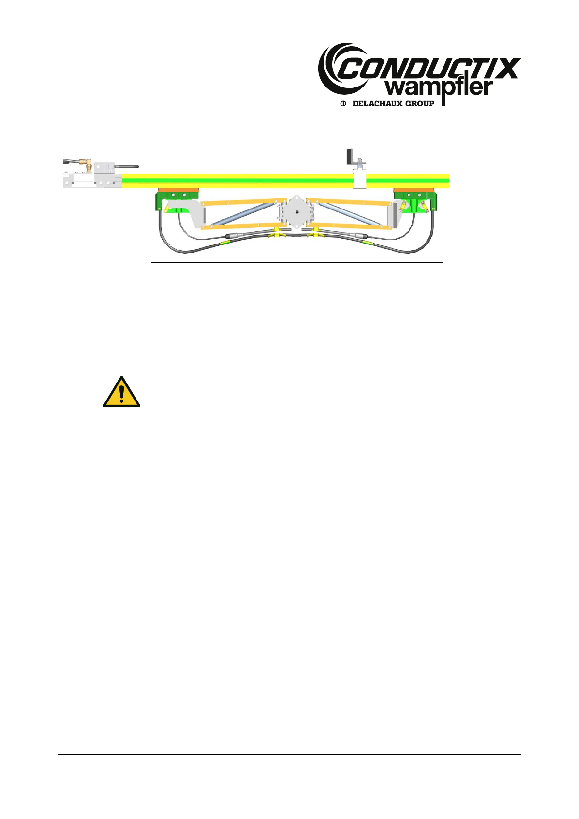
Fig. 18: Installation of the ProfiDAT® expansion element (shown without connecting cable)
1
2
ProfiDAT® Data Transmission System
6.4 Mechanical Installation
Personnel:
Installation by technical personnel only
At least two people
6.4.1 Installation of the Expansion Element
Depending on the system type, the installation of one or more expansion elements is necessary. The air gap in the expansion element
must be adjusted depending on the ambient temperature during installation. Both expansion joints of the expansion element must
have the same air gap.
Starting from the left-hand end of the system, the first expansion element for the ProfiDAT® profile is installed. All other expansion
elements are mounted at intervals of at most 50 m. The exact positions of the expansion elements can be found in the system layout.
Work steps:
Fix the expansion element (1) to the support structure using two fastening screws (2).
Read the air gap "s" from the table in Fig. 19 and adjust it.
MAL0514-0005b-EN
www.conductix.com translated document page 39 of 82
Page 40

Mounting Instructions
Programm 0514
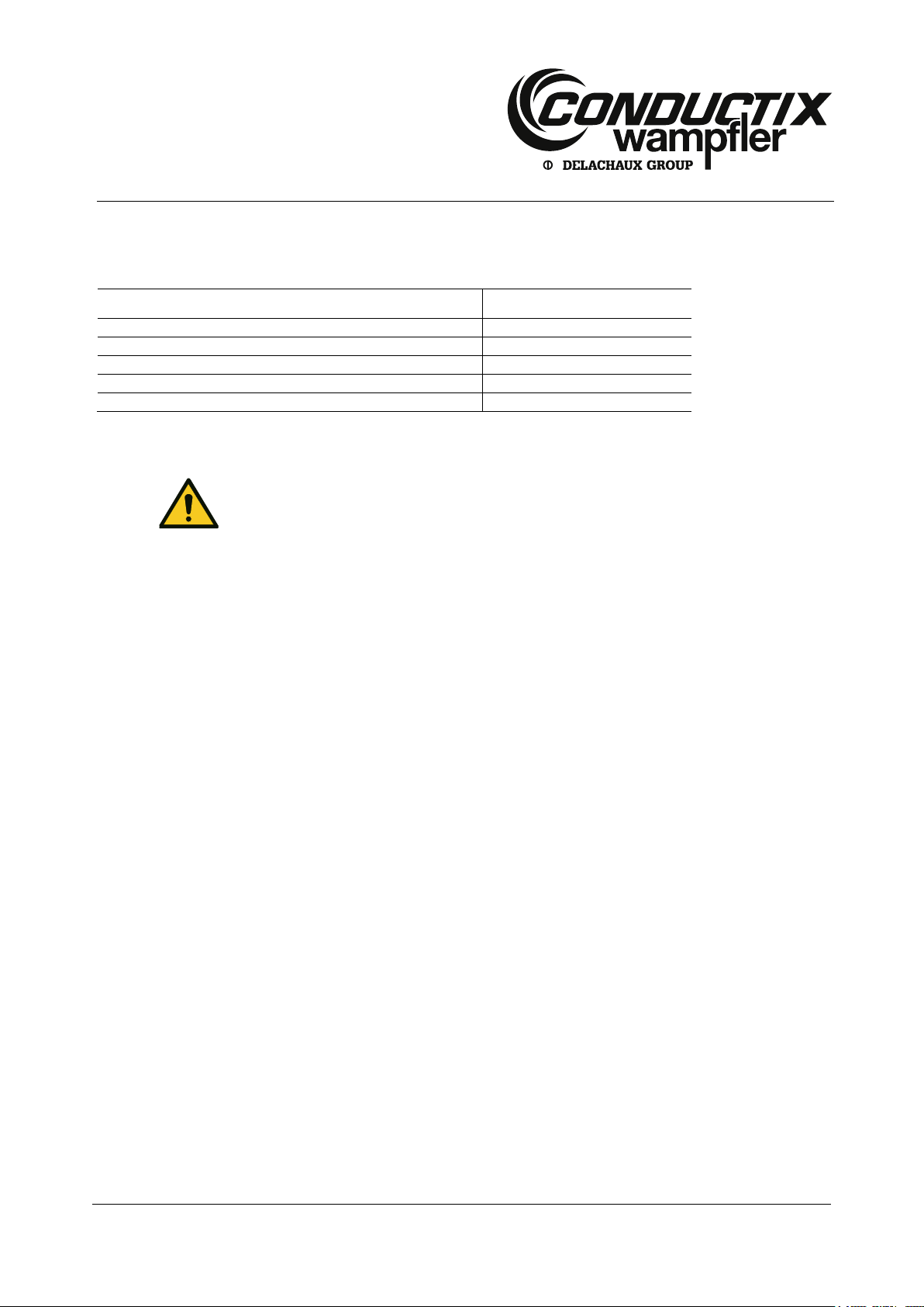
Fig. 19: Determining the air gap for the expansion element
Ensure that the air gaps on the expansion elements are not displaced during the further
installation of the profiles!
-10
-20
-30
+10
0
t max (C°)
+60
+50
+40
+30
+20
0 5 10 15 20 25 30 35 40 45
s (mm)
2
3
1
-10
-20
-30
+10
0
t min (C°)
+40
+30
+20
Air gap
Ambient temperature during installation (°C).
t
max
= maximum average temperature
t
min
= minimum average
temperature
ProfiDAT® Data Transmission System
Determining the Air Gap:
Procedure:
(1) Determine t
max
and t
and enter them on the axes, then draw a connecting line (1) from t
min
(2) Measure the ambient temperature during installation and mark it horizontally.
(3) Drop a line down from the intersection of the two lines, and read off the air gap to adjust.
Example (as entered):
(1) t
= 40 °C; t
max
= -30 °C;
min
(2) Ambient temperature during installation = 0 °C
(3) Air gap = about 26 mm
max
to t
min
.
MAL0514-0005b-EN
www.conductix.com translated document page 40 of 82
Page 41

Mounting Instructions
Programm 0514
Fig. 20: Hanger-clamp installation
Fig. 21: Installation of the ProfiDAT® profile on the support structure.
Fig. 22: Hanger clamp for installation on a C-rail
Pay attention to the alignment of the ProfiDAT® profiles!
One side is marked with two longitudinal grooves (L). Install the profiles so that the longitudinal
grooves are always on the same side.
After installation, it must still be possible to freely rotate the rail clamp.
2
1
2
1
3
4
5
6
4
5
6
ProfiDAT® Data Transmission System
6.4.2 Mounting the ProfiDAT
Work steps:
Push 2 hanger clamps (1) onto the ProfiDAT
®
Profile
®
profile (2).
Insert the ProfiDAT
secure the hanger clamps with the nut (5) and washer (4).
Hold the aluminum spacer (6) with an SW24 open-ended spanner and then firmly tighten the nut (5).
®
profile (2) with hanger clamps (1) into the support structure (3) from below, or push it into the C-rail, and
MAL0514-0005b-EN
www.conductix.com translated document page 41 of 82
Page 42

Mounting Instructions
Programm 0514
Fig. 23: Mounting the ProfiDAT® profile on an expansion element
CAUTION!
Both profiles must be directly next to one another. The gap must be no more than 0.5 mm wide!
The sliding surfaces for the carbon brushes must be level with one another and deburred.
Fig. 24: Mounting the rail connectors on the ProfiDAT® profile
The center of the rail connector is marked with a notch (K).
7
2
10
9
2
K
9
11
10
8
ProfiDAT® Data Transmission System
Push the ProfiDAT
®
profile (2) toward the expansion element (7) and insert it into the PE rail connector (8) on the expansion
element until it reaches the center.
Secure the PE rail connector (8) to the ProfiDAT
®
profile (2) with the two threaded pins (9).
Tighten the four lateral flange screws (10) on the connector.
Push a rail connector (11) onto the mounted ProfiDAT
®
profile (2) until it reaches the center of the connector.
Fix the rail connector (11) with the two threaded pins (9).
Push the next ProfiDAT
®
profile into the installed connector (11) insert and secure it with the two threaded pins.
Tighten the four lateral flange screws (10) on the connector.
Install all further ProfiDAT
®
profiles in the same way.
MAL0514-0005b-EN
www.conductix.com translated document page 42 of 82
Page 43

Mounting Instructions
Programm 0514
Fig. 25: PE rail connector mounted on the expansion element
The center of the rail connector is marked with a notch (K).
Always use a PE connector on both sides of the expansion element!
ATTENTION!
Both profiles must be directly next to one another. The gap must be no more than 0.5 mm wide!
The sliding surfaces for the carbon brushes must be aligned level with one another and be free
of burrs.
Observe the tightening torques for flange screws (5) and set screws (2):
Wrench (5): 20 Nm
Hex key (2): 8 Nm
1
C 3 2
ProfiDAT® Data Transmission System
6.4.3 Installing the PE rail connector
Steps:
Push a PE rail connector (1) onto the left profile of the expansion element (3) or in the ProfiDAT
®
-Profil as in Fig. 26.
Fasten the PE rail connector (1) with the two threaded pins (2).
Push the next ProfiDAT
Fasten the ProfiDAT
Tighten the four lateral flange screws (5) with locking edge washer (6) on the connector (see Fig. 27).
®
profile (4) into the rail holder and push it into the rail connector (1) until it reaches the center.
®
profile (4) to the the rail connector (1) with the two set screws (2).
MAL0514-0005b-EN
www.conductix.com translated document page 43 of 82
Page 44

Mounting Instructions
Programm 0514
Fig. 26: Mounting the rail connectors on the ProfiDAT® profile
The center of the rail connector is marked with a notch (K).
Check that all four flange screws (5) are secured by a locking edge washer (6) between the screw head
and rail connector.
The anchor point must be installed before the hanger clamp is fastened to the support structure.
1
5
6
2 4 1
C
5
6
ProfiDAT® Data Transmission System
6.4.4 Installing the rail connector (without PE)
Steps:
Push a rail connector (1) onto the mounted ProfiDAT
®
profile (4) until it reaches the center.
Fix the rail connector (1) with the two threaded pins (2).
Install all further ProfiDAT
Fig. 27: Screw lock with locking edge washer
®
profiles (4) in the same way.
6.4.5 Installing the Anchor Point
The hanger clamps are designed as sliding suspension devices so that profiles can expand or contract as the temperature changes.
To this end, it is necessary to install defined anchor points and expansion elements (see chapter 6.4.1). The positions of the anchor
points are indicated in the system layout.
MAL0514-0005b-EN
www.conductix.com translated document page 44 of 82
Page 45

Mounting Instructions
Programm 0514
Fig. 28: Installed anchor point
Fig. 29: Marking the gap on the insulating profile
Mark the two sections A and B so that they are not confused during installation.
Fig. 30: Trimming the insulating profile
A
B
A
B
ProfiDAT® Data Transmission System
Work steps:
Mark the distance from the hanger clamp and interfaces on the insulating profile.
The gap must be at least 86 mm.
Remove the insulating profile from the aluminum profile.
Cut the marked gap out of the insulating profile. When doing this, insert a surplus piece of ProfiDAT
ample) into the insulating profile so that it does not break during the cutting process. See also chapter 6.4.7.
®
profile (an offcut, for ex-
MAL0514-0005b-EN
www.conductix.com translated document page 45 of 82
Page 46

Mounting Instructions
Programm 0514
Fig. 31: Installing the PE rail connector PE and insulating profiles
Fig. 32: Pushing on the anchor point
Fig. 33: Installing the anchor point
1
A B 3
4
5
3
A
B
ProfiDAT® Data Transmission System
Push section A, a PE rail connector (1) and section B onto the aluminum profile and align them. Comply with the distances
specified in Fig. 31.
Fasten the PE rail connector with the two threaded pins.
Tighten the four lateral flange screws on the connector.
Push the anchor point (3) onto the hanger clamp (4) from above.
Install the anchor point (3) on the PE rail connector with two screws (5).
Install the hanger clamp with profile on the support structure (see chapter 6.4.2, Fig. 21).
MAL0514-0005b-EN
www.conductix.com translated document page 46 of 82
Page 47

Mounting Instructions
Programm 0514
Fig. 34: Installing the entry funnel
CAUTION!
Note that there are left- and right-handed versions of the entry funnel!
The insulating profile of the ProfiDAT® profile must always be 138 mm shorter than the aluminum
profile.
Fig. 35: Trimming the ProfiDAT® profile
1
4
3
2
ProfiDAT® Data Transmission System
6.4.6 Installing the Entry Funnel
Systems with drive-in/out zones require the installation of an entry funnel so that the current collector can be driven in and out of the
profile.
Work steps:
Push the entry funnel (1) onto the drive-in zone from underneath and fasten with two screws (2) with nuts (3) and washers (4).
Install the second entry funnel in the same way.
6.4.7 Adjusting the length of the ProfiDAT
The ProfiDAT® profiles at the ends of the section can be adjusted in length.
Work steps:
Determine the length of ProfiDAT
®
profile required.
®
Profile
MAL0514-0005b-EN
www.conductix.com translated document page 47 of 82
Page 48

Mounting Instructions
Programm 0514
Fig. 36: Insulation profile (1) aluminum rail (2) clamping surface (A)
1
A
2
0.3 mm x 45°
External edges
burr-free
Internal edges
burr-free
ProfiDAT® Data Transmission System
The cutting direction (1) must be from the open profile side, so from top to bottom (see Fig. 35).
Saw insulation profile and aluminum rail separately and at right angles with a chop saw. Use the clamping surface A (see
Fig. 36) so that the inside of the aluminum rail is not deformed.
After cutting the aluminum rail, make a chamfer of max. 0.3 mm x 45° on the aluminum rail with a key file (see Fig. 37). This is
important to prevent wear of the sliding contact! Remove burrs from all other sharp edges with a key file!
Fig. 37: ProfiDAT® profile burr-free
MAL0514-0005b-EN
www.conductix.com translated document page 48 of 82
Page 49

Mounting Instructions
Programm 0514
Fig. 38: Installation of an infeed antenna on an entry funnel
Fig. 39: Install the infeed antenna on the profile
CAUTION!
Both profiles must be directly next to one another. The gap must be no more than
0.5 mm wide!
The sliding surfaces for the carbon brushes must be level with one another and deburred.
4
1
2
4 3 5
9 7 8
6
5
ProfiDAT® Data Transmission System
6.4.8 Installing the Infeed
The infeed is installed either at the beginning/end of the system (end infeed) or within the system (section infeed). Depending on
the system, the end infeed is via an infeed antenna directly on the profile or in conjunction with an entry funnel.
6.4.8.1 Installing an End Infeed
Infeed antenna on entry funnel:
Push the infeed antenna (4) onto the end cap (3) on the drive funnel (1).
Fix the infeed antenna (4) with the frontal hexagonal-socket-headed screws (2) of the end cap (3).
Infeed antenna on the profile:
Push a connector (6) onto the last ProfiDAT
Insert the infeed antenna (4) up to the stop in the connector (6) of the last ProfiDAT
Secure the infeed antenna (4) on the connector with the two threaded pins (8).
®
profile (7) and secure it with the two threaded pins.
®
profile (7).
Tighten the four lateral flange screws (9) on the connector (6).
Attaching the connecting cable:
Push the heat-shrink sleeve onto one end of the connecting cable.
Fasten/screw the connecting cable to the socket (5) of the infeed antenna (4).
MAL0514-0005b-EN
www.conductix.com translated document page 49 of 82
Page 50

Mounting Instructions
Programm 0514
Depending on the version, the angled plug of the connecting cable lies parallel or perpendicular
to the ProfiDAT® profile.
CAUTION!
The cable must not be crushed!
Respect the bending radius of the cable (at least 40 mm).
Fig. 40: ProfiDAT® section infeed
The angled plug of the connecting cable lies parallel to the ProfiDAT® profile.
1 2 1
ProfiDAT® Data Transmission System
Lay the cable to the infeed switching cabinet/transceiver.
Secure the cable run to the support structure with cable ties (drive-in zone, steel structure, etc.).
Push the heat-shrink sleeve over the angled plug and socket (5) on the infeed antenna (4) and shrink it with a heat gun.
6.4.8.2 Installing a Section Infeed
The section infeed is installed at the expansion element. Two infeed antennas are already integrated here.
Attaching the connecting cable to the expansion element:
Push the heat-shrink sleeve onto one end of the connecting cable.
Fasten/screw the connecting cable to the socket (1) of the expansion element (2).
Lay the cable to the infeed switching cabinet/transceiver.
Fasten the cable run to the support structure with cable ties.
Attach the second connection cable in the same manner.
6.4.9 Connecting the ProfiDAT
After the ProfiDAT® profile has been installed on the entire line, recheck the air gaps on the expansion elements for the correct
measurement. The connection of the ProfiDAT® to the entry funnel is then installed. To do this, the ProfiDAT® profile must be cut to
length in situ (see chapter 6.4.3). The entry funnel also has an expansion function. Set the air gap at the entry funnel to half the value
used for the air gap at the expansion element.
®
Profile to the Entry Funnel
MAL0514-0005b-EN
www.conductix.com translated document page 50 of 82
Page 51

Mounting Instructions
Programm 0514
If a temperature sensor is to be used (see chapter 6.4.15) the bracket for it must be installed
during this step!
The insulation profile of the ProfiDAT® must always be 138 mm shorter than the aluminum
profile.
Fig. 41: Adjusting the ProfiDAT® profile to the entry funnel
Fig. 42: Installing the terminating unit
CAUTION!
Both profiles must be directly next to one another. The gap must be no more than 0.5 mm wide!
The sliding surfaces for the carbon brushes must be level with one another and deburred.
X
Y
3
2
1
3 2 1 4 5
6
ProfiDAT® Data Transmission System
Work steps:
Displace the end cap (1) with infeed antenna (2) and adjust the air gap to size “X” (half the size of the air gap of the expansion
joint).
Measure the dimension “Y” (from the start of the ProfiDAT
Trim a ProfiDAT
Insert and connect the trimmed ProfiDAT
®
profile to dimension “Y”; see chapter 6.4.3.
®
profile.
®
profile infeed antenna (2) to the next ProfiDAT® profile (3)).
6.4.10 Installing the Terminating Unit
The terminating unit differs from the infeed unit by having a terminating resistor (pre-installed). No cable is attached here.
Work steps:
Insert the terminating unit (1) up to the stop in the connector (2) of the last ProfiDAT
®
profile (3).
Secure the terminating unit on the connector with the two threaded pins (4).
Tighten the four lateral flange screws (5) on the connector.
MAL0514-0005b-EN
www.conductix.com translated document page 51 of 82
Page 52

Mounting Instructions
Programm 0514
Fig. 43: Installing dual current collectors
Fig. 44: Inserting the dual current collector into the profile from below
1
2
1
5 4 3
6
6
2
ProfiDAT® Data Transmission System
Push the heat-shrink sleeve over the terminating resistor (6) and the socket on the terminating unit, and shrink with a
heat gun.
6.4.11 Installing the Current Collector
There are two versions of the current collector: single and dual current collectors.
6.4.11.1 Installing dual Current Collectors
The dual current collector consists of two identical current-collecting arms. These are connected with the screws supplied and attached to the towing arm. Minimum conductor spacing 50 mm.
Work steps:
Position both current collector arms (1) on the towing arm (2).
Fix the current collector arms (1) with two screws (3), washers (4) and nuts (5).
For systems without entry funnels: Insert the current-collecting heads (6) into the ProfiDAT
Align the current collector to the profile.
®
profile (2) from below.
MAL0514-0005b-EN
www.conductix.com translated document page 52 of 82
Page 53

Mounting Instructions
Programm 0514
CAUTION!
Make sure that the current collector is installed with its central axis exactly on the central axis of
the ProfiDAT® profile, and that the specified installation distance between the towing arm and the
sliding surface is observed (see system layout).
In order to ensure the full functional freedom of the current collectors, the connecting cables must
be highly flexible and, with the help of the cable clamps located on the current collector, fixed in
such a way that no tensile or torsional forces are transferred to the current-collecting head.
Fig. 45: Installing a single current collector
Fig. 46: Inserting the single current collector into the profile from below
CAUTION!
Make sure that the current collector is installed with its central axis exactly on the central axis of
the ProfiDAT® profile, and that the specified installation distance between the towing arm and the
sliding surface is observed (see system layout).
In order to ensure the full functional freedom of the current collector, the connecting cable must
be highly flexible and, with the help of the cable clamps located on the current collector, fixed in
such a way that no tensile or torsional forces are transferred to the current-collecting head.
1 2 5 4 3
7
6
ProfiDAT® Data Transmission System
6.4.11.2 Installing a single Current Collector
The single current collector has only one current-collecting arm. This is fastened to the counterpart on the towing arm with the screws
supplied.
Work steps:
Position the current-collecting arm (1) and the counterpart (7) on the towing arm (2).
Secure the current-collecting arm (1) with the two screws (3), washers (4) and nuts (5).
For systems without entry funnels: Insert the current-collecting head (6) into the ProfiDAT
Align the current collector to the profile.
®
profile from below.
MAL0514-0005b-EN
www.conductix.com translated document page 53 of 82
Page 54

Mounting Instructions
Programm 0514
ProfiDAT® Data Transmission System
6.4.12 Installing the PE Cable on the ProfiDAT
The ProfiDAT® profile must be connected to the customer's PE cable at the start of the system. This cable must be a PE cable and
thus marked green-yellow (see Fig. 47). The cable cross-section can be determined by the customer; it must be designed at least
equal to half the phase current.
Steps:
Fasten screw DIN 933 (2), locking washer DIN 6798 (6), PE pipe (3) with cable lug (4), locking washer (7) and nut DIN 934 (8)
to connector PE (1).
Attach the grounding symbol below the cable lug to the connector (1).
At each 5th rail connection point, a PE connector and a grounding wire connected to the steel construction must be installed. For this
purpose, an expansion element can be used.
The conductor cross section of the grounding cable may be specified by the customer, but must be at least 16 mm². PE rail connectors are used to connect the grounding cable to the ProfiDAT® profiles.
Steps:
Mark the grounding cable (3) with the cable lug (4) (for M10 screw) at both ends green-yellow (5).
Fasten screw DIN 933 (2), locking washer DIN 6798 (6), PE pipe (3) with cable lug (4), locking washer (7) and nut DIN 934 (8)
to connector PE (1).
®
Profile
Attach the grounding symbol below the cable lug to connector PE (1).
Connect the unconnected end to the steel structure on site and mark the connection point with the grounding symbol.
Fig. 47: PE line is connected to the ProfiDAT® profile
MAL0514-0005b-EN
www.conductix.com translated document page 54 of 82
Page 55

Mounting Instructions
Programm 0514
Fig. 48: Positions of trace-heating conductors in the profile
Fig. 49: Trace-heating conductor emerging at the infeed antenna
Fig. 50: Trace-heating conductor emerging at the infeed/terminating unit
1
1
1
2
1
2
ProfiDAT® Data Transmission System
6.4.13 Use of the ProfiDAT
If the ProfiDAT® profile is used without the PE function, it must nevertheless be connected to the grounded crane/steel structure.
The following steps must be performed when the PE function is not used:
Connect both ends to the crane construction which has been grounded by the customer.
Use a green-yellow grounding cable (minimum cross section 25 mm
Label PE connection points with grounding marks.
®
profile without PE function
2
) (see Fig. 47).
6.4.14 Installing Trace Heating (optional)
The trace heater is intended to prevent the running surface of the profiles from icing. The trace heater is an additional conductor that
has to be introduced during the installation of the ProfiDAT® profile. It is led out of the groove in the side and wired in the infeed
terminal box (see chapter 6.6)
Work steps:
Start the installation of the trace-heating cable (1) at the infeed.
Pull the aluminum profile out of the insulation.
Remove burrs and sharp edges with a file.
Lay the trace-heating cable in the aluminum profile.
Slide the insulating profile over the aluminum profile.
Install the ProfiDAT
Pull the heating cable taut by hand and check whether the heating cable can move freely.
MAL0514-0005b-EN
www.conductix.com translated document page 55 of 82
®
profile (see chapter 6.4.2).
Page 56

Mounting Instructions
Programm 0514
CAUTION!
When connecting the ProfiDAT® profiles, make sure that the trace-heating cable is not damaged.
Before taking into operation, use an insulation tester (test voltage at least 500 V, maximum 2000
fold, minimum insulation resistance 500 Ohm/V) to check that the insulation of the heating cable
is undamaged.
Fig. 51: Temperature sensor at the infeed antenna
Fig. 52: Temperature sensor at the infeed antenna for funnel
It is not possible to retrofit a PE rail connector in a system with C-rails!
1
3
2
ProfiDAT® Data Transmission System
Install trace heating in all ProfiDAT
Lead the trace-heating cables out of the groove to the terminal box for the infeed.
®
profiles in the same way.
6.4.15 Mounting a Temperature Sensor (optional)
The temperature sensor is connected directly to the ProfiDAT® profile.
Work steps:
The temperature sensor (1) is pre-installed on the infeed unit (2).
Run the temperature-sensor cable (3) to the profile-heating controller switching cabinet and connect it.
6.4.16 Retrofitting of a PE Rail Connector (Ground)
If the existing grounding of the profile is insufficient, a PE rail connector has to be retrofitted to the ProfiDAT® profile. The exact
position must be determined based on the system layout.
Work steps:
Center the insulating profile on the aluminum profile so that both ends of the insulating profile are at the same distance from the
ends of the aluminum profile.
MAL0514-0005b-EN
www.conductix.com translated document page 56 of 82
Page 57

Mounting Instructions
Programm 0514
Fig. 53: Marking the profile
Fig. 54: Loosen the connector on the ProfiDAT® profile
Fig. 55: Dismantling the ProfiDAT® profile
1
6
9
8 7 1 2 4
3
5
ProfiDAT® Data Transmission System
Measure the required distance to the cable penetrations in the support structure and mark the position on the ProfiDAT
Make markings on the insulating profile and the aluminum profile!
Remove the marked profile (1). To do this, loosen the four lateral flange screws (2) and the threaded pins (3) of the two rail
connectors (4) on the left and right of the profile.
Move the rail connectors (4) so that the marked profile (1) can be removed. The insulating profiles (5) of the two adjacent pro-
files to the left and right may also need to be moved.
®
profile.
Remove the hanger clamps (6) with the marked profile (1). To do this, loosen the nut (7) and disc (8) and remove the hanger
clamp from the support structure (9).
Pull the ProfiDAT
Remove the insulating profile from the aluminum profile.
MAL0514-0005b-EN
www.conductix.com translated document page 57 of 82
®
profile (1) out of the hanger clamps (6).
Page 58

Mounting Instructions
Programm 0514
Fig. 56: Marking the cutting points on the insulating profile
Mark the two sections A and B so that they are not confused during installation.
Fig. 57: Installing the PE rail connector
A
B
A
B
2
10
3
ProfiDAT® Data Transmission System
Starting from the marked position, make one marking to the left and another to the right at 70 mm each.
Cut the marked gap out of the insulating profile. When doing this, insert a surplus piece of ProfiDAT
for example) into the insulating profile so that it does not break during the cutting process. See also chapter 6.4.7.
Push section A onto the aluminum profile.
Push a PE rail connector (10) onto the aluminum profile and align it with the marking.
Secure the PE rail connector (10) with the threaded pins (3).
Tighten the four lateral flange screws (2) on the connector.
Push section B onto the aluminum profile.
Push the hanger clamps (6) back onto the ProfiDAT
Insert the ProfiDAT
with the nut (7) and the washer (8) (see Fig. 55).
®
profile (1) with hanger clamps (6) into the support structure (9) from below and secure the hanger clamps
®
profile (1).
®
profile (a profile offcut,
Reconnect the profile with the adjacent profiles on the right and the left. To do this, push the rail connectors onto the profile as
far as the center of the connector, secure with the threaded pins and tighten the four lateral flange screws on the connector.
See chapter 6.4.2.
Connect the PE cable, see chapter 6.4.12.
MAL0514-0005b-EN
www.conductix.com translated document page 58 of 82
Page 59

Mounting Instructions
Programm 0514
DANGER!
Risk of death by electrical shock!
Contact with energized components can lead to death or severe injury by electrical shock.
There is also a risk of injury from shock reactions, falling or being thrown across the room as a
result of an electrical shock.
Disconnect the system from the power at the main switch.
If there is no main switch, disconnect the energy source from the system according to
the instructions of the system manufacturer.
Secure the system against being switched on again.
Confirm that the power has been disconnected.
Ground and short-circuit parts of the system disconnected from power.
Cover or block off adjacent energized components,
Before each start-up, test the insulation resistance according to locally applicable
technical standards, directives and laws.
ProfiDAT® Data Transmission System
6.5 Electrical Installation
MAL0514-0005b-EN
www.conductix.com translated document page 59 of 82
Page 60

Mounting Instructions
Programm 0514
DANGER!
Danger of death due to incorrect installation!
The incorrect or improper installation of electrical components can lead to death or severe injury
by electrical shock. There is also a risk of injury from shock reactions, falling or being thrown
across the room as a result of an electrical shock.
Have the power supply in the infeed switching cabinet installed only by professional
electricians.
Fig. 58: Dimensions and holes for the power feed cabinet
Fig. 59: Transceiver Ethernet connection
ProfiDAT® Data Transmission System
6.5.1 Installing the ProfiDAT
®
Infeed Switching Cabinet
Work steps:
Fasten the switching cabinet to the angle bracket with four screws.
Connecting the Ethernet plug at the transceiver:
1. Insert the bare cable through the screw connection.
2. Install the Ethernet plug (RJ45) on the cable.
3. Tighten the screw connection.
4. Insert the Ethernet connector (RJ45) into socket P1 or P2 (2) on the transceiver (see Fig. 59).
Observe the information and safety instructions in the manufacturer's documentation!
Connect the power supply (AC) for the power supply switching cabinet.
Connect the grounding cable of the power supply switching cabinet.
Connect the connecting cable (HF cable) (see chapter 6.5.3).
MAL0514-0005b-EN
www.conductix.com translated document page 60 of 82
Page 61

Mounting Instructions
Programm 0514
Fig. 60: Connections on the transceiver
CAUTION!
Do not reverse the polarity of the connections!
ProfiDAT® Data Transmission System
6.5.2 Installing a ProfiDAT
Also observe the information and safety instructions in the manufacturer's documentation when installing the transceiver!
Work steps:
Fasten the ProfiDAT
®
transceiver to the DIN rail (35 mm) in the switching cabinet of the mobile system component.
®
Transceiver on a Mobile System Component
Connecting the cable to the power supply (24 V) on the transceiver:
Direct infeed via the 4-pole socket: Connection pinout (see Fig. 60):
L1+: 24 V DC
M1: Chassis ground
M2: Chassis ground
L2+: 24 V DC
Power over Ethernet via the RJ45 Ethernet interface P2 (2).
Connect the Ethernet plug (RJ45) to the transceiver (P1 or P2).
Connect the connecting cable (HF cable) (see chapter 6.5.3).
MAL0514-0005b-EN
www.conductix.com translated document page 61 of 82
Page 62

Mounting Instructions
Programm 0514
CAUTION!
Do not crush the cable!
Comply with the bending radius of the cable.
CAUTION!
Do not crush the cable!
Comply with the bending radii of the cables.
CAUTION!
Avoid tensile stress on the ProfiDAT® adapter cable.
ProfiDAT® Data Transmission System
6.5.3 Installing the Connecting Cable (HF cable) on the Infeed Antenna
The connecting cable to the infeed antenna on the ProfiDAT® profile is installed between the transceiver in the infeed switching
cabinet and the connection on the infeed antenna.
Work steps:
Push a heat-shrink sleeve onto one end of the connector cable.
Fasten/Screw the straight N plug on the connector cable onto the socket at the power feed cabinet.
Run the connecting cable to the socket of the infeed antenna.
Push a heat-shrink sleeve onto the other end of the connector cable.
Fasten/Screw the angled N plug on the socket of the infeed antenna.
Fasten the cable run to the support structure with cable ties, etc. Stow the excess cable neatly.
Push both heat-shrink sleeves over the plugs and socket and shrink them with a heat gun.
6.5.4 Installing the Connection Cable (HS Cable) on the Transceiver
The connecting cables of the antenna on the current collector are installed on the transceiver in the switching cabinet of the mobile
system component.
Also observe the information and safety instructions in the manufacturer's documentation when installing the connecting cables!
Work steps:
Installing the ProfiDAT
Run the connecting cable to the adapter cable.
Connect the connection cable to the ProfiDAT
Secure the cable run with cable ties, etc.
Secure the connection point between the connection cable and the ProfiDAT
®
adapter cable on the transceiver.
®
adapter cable.
®
adapter cable (strain relief).
Install the second connection cable in the same manner.
MAL0514-0005b-EN
www.conductix.com translated document page 62 of 82
Page 63

Mounting Instructions
Programm 0514
DANGER!
Risk of death by electrical shock!
When working on these components, death or injury may result from electrical shock, burns,
or electrical arcs, because they are electrically live:
Conductor rails and current collectors, cables and connections, servomotors, switching
cabinets and control systems.
Before entering the danger zone and working on these components:
Disconnect the system from the power at the main switch.
If there is no main switch, disconnect the energy source from the system according to
the instructions of the system manufacturer.
Secure the system against being switched on again.
Confirm that the power has been disconnected.
Ground and short-circuit parts of the system disconnected from power.
Cover or block off adjacent energized components,
Before each start-up, test the insulation resistance according to locally applicable
technical standards, directives and laws.
WARNING!
Risk of fire!
Overloaded cables are a fire risk!
Before commissioning, test the product in accordance with the manufacturer’s
checklist.
Only have testing carried out by qualified technicians who are familiar with both the
product and the regulations concerning workplace safety and accident prevention.
ProfiDAT® Data Transmission System
6.6 Profile-heating (optional)
Condensation on the contact surface of the ProfiDAT® profile can lead to insulation faults, as well as increasing oxidation of the rail
and wear of the carbon brushes. The conductor rail heating is designed to prevent condensation, hoarfrost or ice from forming around
the contact surface.
To this end, the ProfiDAT® profile is temperature controlled using an optional heating cable starting at a temperature near the dew
point or the point of formation of frost and ice. The trace-heating cable is laid in the cavity of the profile and is supplied as a conductive
loop with external auxiliary power.
The heating power required depends on a number of parameters. It must be taken into consideration that whether ice forms on a
profile or not depends on the installation situation of the profile and its environment,
Where a profile is exposed to wind, wind-chill effects can cause ice to form even when the temperature is still above 0°C.
The profile-heating controller has temperature and dew-point sensors. The profile heating is switched on if the temperature falls
below a certain value and reaches the dew point.
Electrical hazards and sources of danger
MAL0514-0005b-EN
www.conductix.com translated document page 63 of 82
Page 64

Mounting Instructions
Programm 0514
Fig. 61: Profile-heating switching cabinet
ProfiDAT® Data Transmission System
6.6.1 Profile-heating Controller
The figure below shows the switching cabinet for the profile heating with the three indicators on the front side.
The green lamp (1) indicates the operational readiness of the controller.
The white lamp (2) indicates whether the heating is switched on or off.
The red warning lamp (3) indicates faults. Faults include, for example, the failure of the circuit breaker or other fuse elements.
MAL0514-0005b-EN
www.conductix.com translated document page 64 of 82
Page 65

Mounting Instructions
Programm 0514
ProfiDAT® Data Transmission System
6.6.2 Profile-heating Components
The profile heating consists of the trace-heating cable, the wiring components and the temperature-dependent power supply.
Trace-heating cable
The trace-heating cable is a resistive heating cable used in different nominal sizes. It is drawn into the cavity between the profile rail
and the profile insulation (see chapter 6.4.14). The external dimensions are designed such that the trace-heating cable passes
through the lateral groove on the infeed antenna or expansion element as well as through the bottlenecks at the connector. Traceheating cables with larger diameters or self-regulating heat tapes with feed and return lines cannot be used.
During installation, ensure that the trace-heating cable insulation is not damaged and that the heating cable is not jammed in the
profile connections. If the trace-heating cable or its insulation is damaged, the heating can fail, a short circuit can occur, or a
connection to the conductor rail can occur (stray voltage).
MAL0514-0005b-EN
www.conductix.com translated document page 65 of 82
Page 66

Mounting Instructions
Programm 0514
WARNING!
This checklist serves as a guide to ensure the safe operation of the electrification system.
The checklist is intended for qualified professionals who install and commission electrification systems and
are familiar with the regulations on safety at work and accident prevention.
The report on the next few pages must be filled out during initial commissioning.
Final customer
Customer no.
Order no.
Place of commissioning
Address
Country
Site no.
System no.
Serial number
ProfiDAT® transceiver
Start of commissioning
Commissioning Engineer
End of commissioning
Name
Date
Signature
ProfiDAT® Data Transmission System
6.7 Checklist and Initial Commissioning
MAL0514-0005b-EN
www.conductix.com translated document page 66 of 82
Page 67

Mounting Instructions
Programm 0514
No.
Description
Remark: OK/not OK
1.
Installation
1.1.
The number of profile hanger clamps is correct (with a maximum spacing of 2500 mm).
1.2.
The expansion elements are correctly installed.
1.3.
The ProfiDAT® profiles are correctly aligned.
1.4.
The current collector is correctly installed. The force between the carbon brushes and the Profi-
DAT® profile is 28 N.
1.5.
The current collector is correctly aligned to the ProfiDAT® profile.
1.6.
There are no objects blocking the movement range of the current collector.
1.7.
The ProfiDAT® connectors are correctly installed (maximum gap of 0.5 mm between profiles;
no vertical or horizontal offset).
1.8.
The infeed modules/infeed unit are/is correctly installed.
1.9.
The terminating unit is correctly installed.
1.10.
The protective conductor cable at the start of the ProfiDAT® profiles is correctly installed.
1.11.
The protective conductor cables are correctly installed on the PE connectors.
1.12.
The carbon brushes are free of grease.
1.13.
The trace-heating system has been correctly installed (if an optional heating system has been
installed).
1.14.
All screws have been tightened according to the specification.
1.15.
The ProfiDAT® transceivers have been correctly installed.
1.16.
The ProfiDAT® infeed cabinet has been correctly installed.
1.17.
All electrical connections have been correctly completed by specialist personnel.
1.18.
All RF cables have been correctly installed.
1.19.
The operating personnel have been trained.
2.
ProfiDAT® connection
2.1.
The stationary ProfiDAT® transceiver is switched on and the LAN is connected
Switch on the 24-V power supply to the ProfiDAT® transceiver and allow the ProfiDAT® trans-
ceiver at least 1 minute to load.
Condition:
“ON” LED is green or flashing orange.
“LAN” LED is green.
ProfiDAT® Data Transmission System
MAL0514-0005b-EN
www.conductix.com translated document page 67 of 82
Page 68

Mounting Instructions
Programm 0514
No.
Description
Remark: OK/not OK
2.2.
The ProfiDAT® transceiver on the mobile system part is switched on and the LAN is
connected
Switch on the 24-V power supply to the ProfiDAT® transceiver and allow the ProfiDAT®
transceiver at least 1 minute to load.
Requirement:
“ON” LED is green or flashing orange.
“LAN” LED is green.
2.3.
ProfiDAT® connection is established
Requirement:
“WLAN” LED is green.
“SER” LED is green
The initial commissioning of the transceiver must occur simultaneou sly with the
commissioning of the system into which the data transmission system is integrated. The
establishment of the connection and transfer of data can only occur once the system has been
switched on and a connection has been established between the antenna on the current
collector and the infeed antenna via the ProfiDAT® profile.
No.
Description
Remark: OK/not OK
3.
Commissioning
3.1.
Current-collector check – low speed
Test: traverse the entire guideway at 10 % of the maximum speed. Monitor the activity of the
current collector on the ProfiDAT® profile watch, especially at joints and the expansion
element.
Required result: The connections and transitions over the whole length of the ProfiDAT® profile
are smooth and the activity of the current collector is problem free at all times.
3.2.
Current-collector test – increased speed
Test: Increase the speed to 30 %, 50 %, 80 %, and finally 100 % of the full speed.
Required result: The activity of the current collector is problem free at all times.
3.3.
Additional functional tests
Required result:
All other functions are carried out in accordance with customer requirements.
ProfiDAT® Data Transmission System
MAL0514-0005b-EN
www.conductix.com translated document page 68 of 82
Page 69

Mounting Instructions
Programm 0514
WARNING!
Risk of death due to suspended loads!
Falling loads can lead to severe injuries or even death.
Never walk under suspended loads.
Only move loads under supervision.
Set down the load before leaving the workplace
Danger of injury due to improper operation!
Improper operations can result in serious personal injury and material damage!
Carry out all operating steps according to the specifications of these mounting
instructions.
Before starting work, ensure that all covers and safety devices are installed and
working property.
Never disable the safety systems during operation.
Maintain order and cleanliness in the working area! Loosely stacked or scattered
components and tools are sources of hazards.
Danger for unauthorized
personnel!
Unauthorized persons who do not meet the requirements described here are not acquainted with the dangers in the working area!
Keep unauthorized personnel away from the working area.
In case of doubt, address the person and direct them away from the working area.
Stop working as long as unauthorized persons are in the working area.
ProfiDAT® Data Transmission System
7 Operation
7.1 Safety
Electrical
Do not exceed the rated voltage specified in chapter 3. The data transmission system can be overloaded by excessive current or
voltage. Danger of fire, destruction of the data transmission system!
Personnel:
The system may only be operated by trained personnel!
Personal protective clothing (this must be worn for all work):
Protective work clothing
Protective footwear
MAL0514-0005b-EN
www.conductix.com translated document page 69 of 82
Page 70

Mounting Instructions
Programm 0514
WARNING!
Danger of injury due to improperly executed maintenance tasks!
Improper maintenance can result in serious injury to person and property.
Before starting work, ensure sufficient space for assembly.
Make sure the installation area is tidy and clean! Loosely stacked or scattered
components and tools are sources of hazards.
If components have been removed, check for proper installation, replace all fastening
elements and comply with screw-tightening torques.
Turn off power switches and secure them against unauthorized switching on.
Use the provided climbing aids and working platforms, whenever installation tasks are
carried out above eye level.
Do not use machine components as climbing aids.
Ensure that process and auxiliary materials are drained, collected and disposed of in a
safe and environmentally friendly manner.
Safety devices that have been removed for installation, service or repair work must be
installed and inspected immediately after the work is complete.
Observe the inspection and maintenance intervals described in the maintenance
instructions.
Ensure that sufficient space for maintenance work is available.
Ensure that powered components are not inadvertently activated during maintenance
work.
Ensure that detached parts do not fall.
Screw joints that were loosened during maintenance work must be retightened and
secured according to instructions.
Fasteners and seals that cannot be reused must be replaced (e.g. self-locking nuts,
disks, splints, O-rings, glued or microencapsulated screws).
Lubrication/Greasing points that are cleaned or wiped during maintenance and repair
work must be relubricated as instructed.
After finishing work, collect all tools and materials and check that all are present.
Disassembled parts and components that were exchanged are to be collected, stored
in a safe place, recycled or returned.
Before entering systems, they must be disconnected from power at the main switch
and secured against unauthorized, unintentional and/or erroneous switching on.
ProfiDAT® Data Transmission System
8 Maintenance and Servicing
8.1 Safety
MAL0514-0005b-EN
www.conductix.com translated document page 70 of 82
Page 71

Mounting Instructions
Programm 0514
Interval
Maintenance work
To be carried out by
14 days: 3- and 4-shift operation
30 days: 2-shift operation
after no more than 300
hours
Visual inspection of ProfiDAT® system components
Proper condition
Proper function
Firm seating of screws and nuts
Deformation
Wear
Damage
Pollution Degree
Corrosion
Operator
Every 4 weeks
Visual and functional inspection
Wear of carbon brushes
Technician
Every 6 months
Visual and functional inspection
Check for ease of motion
All electrical connections and cables
Visual inspection of the components of the ProfiDAT® system
for:
Proper condition
Proper function
Deformation
Wear
Damage
Pollution Degree
Corrosion
Technician
Check of screw connections
Check for firm seating of screws
If necessary tighten to torque (see chapter 6).
Technician
Every 6 months
Inspection of the current collectors
Installation dimensions
Contact force of the carbon brushes
Connector cables
Oil joints and/or bolts
ProfiDAT® Data Transmission System
8.2 Maintenance Plan
The following chapters describe the maintenance tasks required for optimal, trouble-free operation. The tasks specified and performed as per the maintenance plan must be logged.
If regular checks reveal increased wear, the required maintenance intervals should be shortened in accordance with the actual signs
of wear.
Contact the manufacturer in case of any questions regarding maintenance tasks and intervals - see the service address on the last
page.
MAL0514-0005b-EN
www.conductix.com translated document page 71 of 82
Page 72

Mounting Instructions
Programm 0514
Fig. 63: Loosening screws
Fig. 62: Remove the current-collecting head from the ProfiDAT® profile
1
1
3
2
ProfiDAT® Data Transmission System
8.2.1 Documentation
The results of inspections and the measures taken are to be documented in written reports.
Conductix-Wampfler must be informed immediately of any defects or malfunctions that occur during the test phase and within
the warranty period.
8.2.2 Replacement of the ProfiDAT
Required tools:
Allen key, SW5
Work steps:
®
Antenna
Pull the current-collecting head (1) down and out of the ProfiDAT
Loosen the 2 hexagonal-socket-headed screws (3) (without removing them).
®
profile (2).
MAL0514-0005b-EN
www.conductix.com translated document page 72 of 82
Page 73

Mounting Instructions
Programm 0514
Fig. 64: Pulling out the antenna
CAUTION!
Make sure that the carbon brushes (5) do not fall out.
Fig. 65: Inserting the antenna in the head of the current collector
6
4
1
5
4
1
5
ProfiDAT® Data Transmission System
Pull out the antenna (4) in an upwards direction.
Loosen the coupling ring of the cable (6) and disconnect the cable from the antenna (4).
Clean the head of the current collector (1) with a clean cloth.
Connect the cable (6) with the coupling ring to the new antenna.
Insert the antenna (4) between the 2 carbon brushes (5) from above.
MAL0514-0005b-EN
www.conductix.com translated document page 73 of 82
Page 74

Mounting Instructions
Programm 0514
CAUTION!
Make sure that the antenna (4) and at the carbon brushes (5) make contact with the currentcollecting head (1).
Fig. 66: Inserting the current-collecting head into the ProfiDAT® profile
WARNING!
Destruction of the system due to lack of grounding!
Carbon brushes that have been worn down beyond the permitted limit can no longer make
good contact with the ProfiDAT® profile. Poor contact between carbon brush and profile leads
to the loss of the PE connection (ground)! In case of a short circuit, the system is not
grounded.
Regularly check the degree of wear of the carbon brushes.
Under no circumstances continue to use defective or worn out carbon brushes.
Worn out carbon brushes must be exchanged immediately.
Fig. 67: Wear limit of the carbon brush on the ProfiDAT® current collector
1
1
2
ProfiDAT® Data Transmission System
Tighten the 2 hexagonal-socket-headed screws (3; see Fig. 63).
Insert the current-collecting head (1) into the ProfiDAT
8.2.3 Maximum Wear of the Carbon Brushes
®
profile (2) from below.
MAL0514-0005b-EN
www.conductix.com translated document page 74 of 82
Page 75

Mounting Instructions
Programm 0514
Fig. 69: Loosening screws
Fig. 68: Remove the current-collecting head from the ProfiDAT® profile
1
1
3
2
ProfiDAT® Data Transmission System
8.2.4 Replacement of Carbon Brushes on the ProfiDAT
Required tools:
Allen key, SW5
Work steps:
Pull the current-collecting head (1) down and out of the ProfiDAT
®
profile (2).
®
Current Collector
Loosen the 2 hexagonal-socket-headed screws (3) (without removing them).
MAL0514-0005b-EN
www.conductix.com translated document page 75 of 82
Page 76

Mounting Instructions
Programm 0514
Fig. 70: Pull out the carbon brushes
The cable on the antenna does not have to be disconnected.
Fig. 71: Inserting the antenna between the carbon brushes
5
4
1
2.
1.
5
1
4
ProfiDAT® Data Transmission System
Pull out the carbon brushes (4) in an upward direction.
Pull out the antenna (5) in an upwards direction.
Clean the head of the current collector (1) with a clean cloth.
Insert both carbon brushes (4) into the current-collecting head (1) from above.
Insert the antenna (5) between the 2 carbon brushes (4) from above.
MAL0514-0005b-EN
www.conductix.com translated document page 76 of 82
Page 77

Mounting Instructions
Programm 0514
CAUTION!
Make sure that the antenna (5) and at the carbon brushes (4) make contact with the currentcollecting head (1).
Fig. 72: Inserting the current-collecting head into the ProfiDAT® profile
1
1
2
ProfiDAT® Data Transmission System
Tighten both hexagonal-socket-headed screws (3; see Fig. 69).
Insert the current-collecting head (1) into the ProfiDAT
®
profile (2) from below.
MAL0514-0005b-EN
www.conductix.com translated document page 77 of 82
Page 78

Mounting Instructions
Programm 0514
WARNING!
Danger of injury due to improper troubleshooting!
Improper troubleshooting can result in serious injury to person and property.
Contact the manufacturer in case of malfunction.
Allow troubleshooting to be carried out only by personnel from or authorized by the
manufacturer.
CAUTION!
In case of a frequently occurring PROFINET errors:
Inspect the mechanical system.
Ensure that the data load on the ProfiDAT® system does not exceed the limits specified on
page 23.
ProfiDAT® Data Transmission System
9 Troubleshooting
MAL0514-0005b-EN
www.conductix.com translated document page 78 of 82
Page 79

Mounting Instructions
Programm 0514
WARNING!
Danger of injury due to improper dismantling!
Stored residual energy, sharp components, and points and edges on and in the data
transmission system or the required tools can cause injuries.
Before starting work, ensure sufficient space.
Handle open, sharp-edged components with care.
Make sure the workplace is tidy and clean! Loosely stacked or scattered components
and tools are sources of hazards.
Dismount components properly. Be aware of the high dead weight of some
components. If necessary, use lifting gear.
Secure components so that they cannot fall or fall over.
Involve the manufacturer in case of any unclear points.
WARNING!
Note the dangers due to electrical shock, harmful dusts, sharp edges and moving
parts!
DANGER!
Danger of parts falling from above!
Falling parts can lead to severe injuries or even death.
A hazard exists that components fall down, during the disassembly of the data transmission
system. These can lead to extremely severe injuries and even death.
Secure all components against falling during dismantling work.
Never walk underneath the disassembly location.
Barricade the disassembly location.
ProfiDAT® Data Transmission System
10 Dismantling and Disposal
10.1 Safety
10.2 Dismantling
After the end of its service life, the data transmission system must be disassembled and disposed of in an environmentally friendly
manner.
Remove operating and auxiliary materials, as well as residual processing materials, and dispose of them in an environmentally
appropriate manner.
Clean the subassemblies and components properly, and dismantle and dispose of them in compliance with locally applicable
occupational-safety and environmental-protection regulations.
10.2.1 Dismantling the Assembly
MAL0514-0005b-EN
www.conductix.com translated document page 79 of 82
Page 80

Mounting Instructions
Programm 0514
CAUTION!
Environmental damage due to improper disposal!
Electrical waste, electronic components, lubricants, and other auxiliary materials are subject to
hazardous-waste disposal regulations and may only be disposed of by authorized specialists!
ProfiDAT® Data Transmission System
Personnel
May only be carried out by trained technicians
At least two people
Required tools
Open-ended spanner, SW10
Open-ended spanner, SW17
Open-ended spanner, SW24
Allen wrench SW3
Allen key, SW5
Phillips screwdriver
Tools for ensuring safety
10.3 Disposal
In the absence of a return or disposal agreement, dismantled components must be recycled as follows:
All metal parts must be scrapped
Plastic components must be sent for recycling
The other components are to be disposed of according to their material composition.
Local authorities or specialist disposal companies can provide information about environmentally appropriate disposal.
MAL0514-0005b-EN
www.conductix.com translated document page 80 of 82
Page 81

Mounting Instructions
Programm 0514
Seq.
no.
Document No.
Document name
01
C79000-G8900-C322-03
Industrial Wireless LAN, SCALANCE W760/W720 Operating Instructions
02
C79000-G8900-C325-04
Industrial Wireless LAN, SCALANCE W770/W730 Operating Instructions
03
A5E03678337-09
Industrial Wireless LAN SCALANCE W786-x Operating Instructions
04
WV0800-0001-D
Cleaning conductor rails
ProfiDAT® Data Transmission System
11 Additional Documents
11.1 Conformity Declaration
The conformity declaration for this product can be obtained from Conductix-Wampfler on request.
11.2 Other applicable Documents
MAL0514-0005b-EN
www.conductix.com translated document page 81 of 82
Page 82

Mounting Instructions
Programm 0514
Conductix-Wampfler GmbH
Rheinstrasse 27 + 33
79576 Weil am Rhein – Märkt
Germany
Phone: +49 (0) 7621 662-0
Fax: +49 (0) 7621 662-144
info.de@conductix.com
www.conductix.com
ProfiDAT® Data Transmission System
12 Index
Accidents and Malfunctions ................................................ 22
Brief Description ................................................................. 27
Checklist and initial commissioning .................................... 66
Conformity Declaration ....................................................... 81
Copyright .............................................................................. 7
Description of Assemblies .................................................. 28
Dismantling ......................................................................... 79
Disposal ........................................................................ 79, 80
Documents ......................................................................... 81
Electrical installation ........................................................... 59
Explanation of Symbols ........................................................ 8
Functional Principles .......................................................... 27
General Notes ...................................................................... 6
Hazard ................................................................................ 14
Installation and Commissioning .......................................... 36
Intended Use ...................................................................... 11
Interfaces ............................................................................ 23
Limitation of Liability ............................................................. 6
Maintenance and Servicing ................................................ 70
Maintenance plan ............................................................... 71
Material defects .................................................................... 7
Mechanical Installation ....................................................... 39
Modes of Operation............................................................ 32
Operating Conditions ......................................................... 26
Operation ........................................................................... 69
Overview ............................................................................ 27
Packaging .......................................................................... 34
Personal Protective Equipment .......................................... 10
Personnel ............................................................................. 9
Preparations ....................................................................... 37
Profile-heating (optional) .................................................... 63
Safety ................................................................................. 70
Safety ........................................................................... 36, 69
Safety ................................................................................. 79
Safety Devices ................................................................... 21
Shipment ............................................................................ 33
Spare Parts .......................................................................... 7
Technical Specifications..................................................... 23
Technical support ................................................................. 7
Training .............................................................................. 10
Troubleshooting ................................................................. 78
Unauthorized Personnel....................................................... 9
MAL0514-0005b-EN
www.conductix.com translated document page 82 of 82
 Loading...