

Page 1
Conductor Bar Manual
Cluster Bar
964000.5.0
1
IOM CLUSTER BAR MANUAL
Page 2

Conductix Incorporated
The technical data and images which appear in this manual are for informational purposes only. NO WARRANTIES, EXPRESS OR IMPLIED, INCLUDING
WARRANTIES OF MERCHANTABILITY OR FITNESS FOR A PARTICULAR PURPOSE, ARE CREATED BY THE DESCRIPTIONS AND DEPICTIONS OF THE
PRODUCTS SHOWN IN THIS MANUAL. Conductix makes no warranty (and assumes no liability) as to function of equipment or operation of systems
built according to customer design or of the ability of any of its products to interface, operate or function with any portions of customer systems not
provided by Conductix.
Seller agrees to repair or exchange the goods sold hereunder necessitated by reason of defective workmanship and material discovered and reported to
Seller within one year after shipment of such goods to Buyer.
Except where the nature of the defect is such that it is appropriate, in Seller’s judgment, to effect repairs on site, Seller’s obligation hereunder to remedy
defects shall be limited to repairing or replacing (at Seller’s option) FOB point of original shipment by Seller, any part returned to Seller at the risk and cost
of Buyer. Defective parts replaced by Seller shall become the property of Seller.
Seller shall only be obligated to make such repair or replacement if the goods have been used by Buyer only in service recommended by Seller and
altered only as authorized by Seller. Seller is not responsible for defects which arise from improper installation, neglect, or improper use or from normal
wear and tear.
Additionally, Seller’s obligation shall be limited by the manufacturer’s warranty (and is not further warranted by Seller) for all parts procured from others
according to published data, specifications or performance information not designed by or for Seller.
Seller further agrees to replace or at Seller’s option to provide a refund of the sales price of any goods that do not conform to applicable specifications or
which differ from that agreed to be supplied which non-conformity is discovered and forthwith reported to Seller within thirty (30) days after shipment to
the Buyer. Seller’s obligation to replace or refund the purchase price for non-conforming goods shall arise once Buyer returns such goods FOB point of
original shipment by Seller at the risk and cost of Buyer. Goods replaced by Seller shall become the property of Seller.
There is no guarantee or warranty as to anything made or sold by Seller, or any services performed, except as to title and freedom from encumbrances
and, except as herein expressly stated and particularly, and without limiting the foregoing, there is no guarantee or warranty, express or implied, of
merchantability or of fitness for any particular purpose or against claim of infringement or the like.
Seller makes no warranty (and assumes no liability) as to function of equipment or operation of systems built to Buyer’s design or of the ability of any
goods to interface, operate or function with any portions of Buyer’s system not provided by Seller.
Seller’s liability on any claim, whether in contract, tort (including negligence), or otherwise, for any loss or damage arising out of, connected with, or
resulting from the manufacture, sale, delivery, resale, repair, replacement or use of any products or services shall in no case exceed the price paid
for the product or services or any part thereof which give rise to the claim. In no event shall Seller be liable for consequential, special, incidental or
other damages, nor shall Seller be liable in respect of personal injury or damage to property not the subject matter hereof unless attributable to gross
misconduct of Seller, which shall mean an act or omission by Seller demonstrating reckless disregard of the foreseeable consequences thereof.
Seller is not responsible for incorrect choice of models or where products are used in excess of their rated and recommended capacities and design
functions or under abnormal conditions. Seller assumes no liability for loss of time, damage or injuries to property or persons resulting from the use of
Seller’s products. Buyer shall hold Seller harmless from all liability, claims, suits and expenses in connection with loss or damage resulting from operation
of products or utilization of services, respectively, of Seller and shall defend any suit or action which might arise there from in Buyer’s name - provided
that Seller shall have the right to elect to defend any such suit or action for the account of Buyer. The foregoing shall be the exclusive remedies of the
Buyer and all persons and entitles claiming through the Buyer.
2
IOM CLUSTER BAR MANUAL 964000.5.0
Page 3

1.0 Safety
2.0 Installation
2.1 Hanger Clamps
2.2 Splices
2.3 Field Cutting
2.4 Powerfeed
2.5 Anchor Clamps
2.6 Expansion Section
2.7 End Cap
2.8 Transfer Cap
2.9 Collector Mounting Dimensions
3.0 Maintenance
3.1 Warning
3.2 Atmospheric Conditions/Frequency of Use
3.3 Collectors
3.4 Conductors
INDEX
4.0 Troubleshooting
5.0 Typical Installations
IOM CLUSTER BAR MANUAL964000.5.0
3
Page 4
1.0 Safety
1.1 Disconnect Power and follow all lock-out tag-out procedures as described in Appendix A of OSHA Section 1910.147.
1.2 All personnel must practice strict adherence to both local and national safety procedures, codes, regulations, and ordinances.
1.3 All personnel installing a power rail system should be familiar with the layout details and the component locations.
1.4 WARNING: The law recognizes that electrical energy as commonly used in industrial and transit operations is dangerous and capable
of causing serious damage, injury or death. Requirements governing the handling and use of electricity, some general and
some very specific and detailed, are found in various statutes like the Workmen’s Compensation Acts, Employer’s Liability
Acts, National Electrical Safety Code (U.S. Dept. of Commerce), Occupational Safety and Health Administration (OSHA), etc.
and city or local ordinances. When using electrical power, the law imposes the general obligation to use care to protect
against accidental injury or damage to properties.
2.0 Installation
2.1 Hanger Clamps
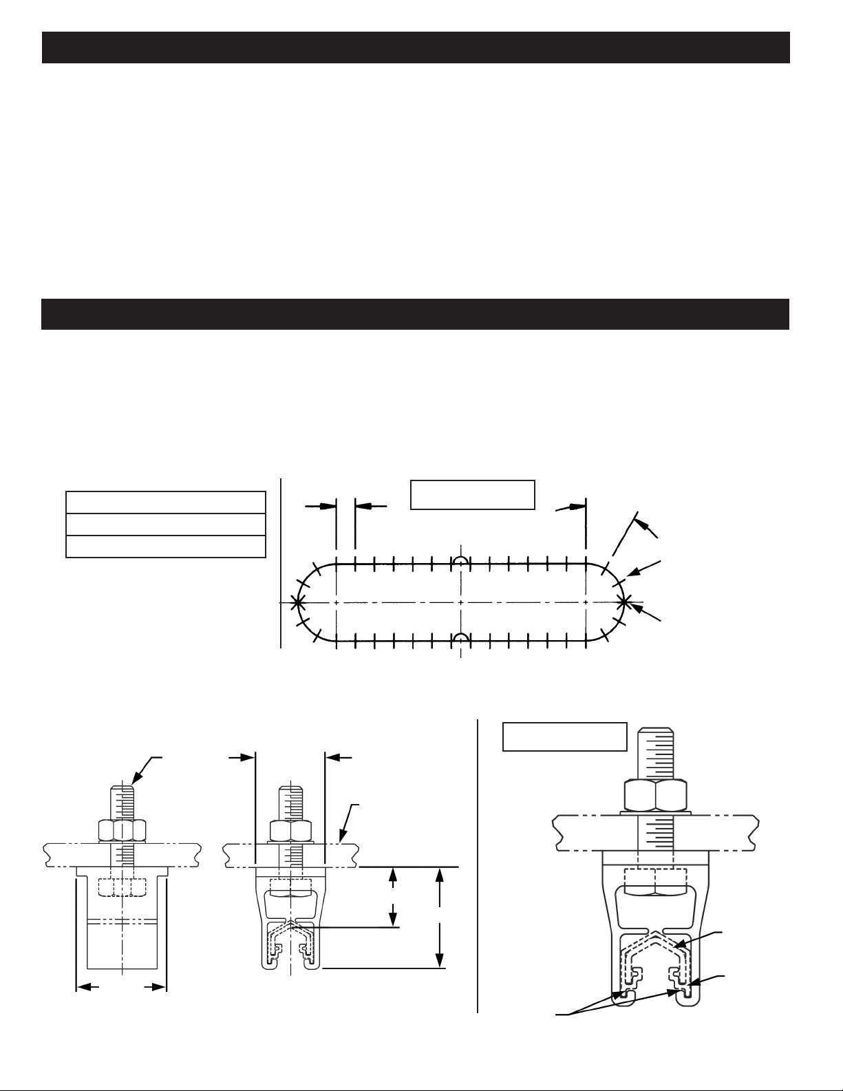
2.1.1 Bolt hanger clamps to support. Be sure hangers are not cocked or
twisted. Torque nut 70 in. lbs.
2.1.2 Maximum spacing of hanger clamps:
3’-0” Max.
1’-6” for curves less than 5’ radius
2’-0” for curves greater than 5’
3’-0” for straights
2.1.5 Specifications for various hanger clamps and brackets are shown
on the diagram below and on the next page:
1/4”-20
3/4” REF
1/4” REF
Mounting Brkt
(By Others)
2.1.3 Spacing is identical for lateral or vertical mounts (see Figure 1).
2.1.4 Snap Cluster Bar with cover into hanger clamps making sure that
bottom of hanger clamps are completely gripping bottom of conductor bar
cover (see Figure 2).
2’-0” Max. Over 5’-0” Radius
Figure 1
1’-6” Max. Under 5’-0” Radius
Hanger Clamp
Anchor Clamp
Figure 2
Mounting Surface
3/4” REF
Contact
Surface
1” REF
4
IOM CLUSTER BAR MANUAL 964000.5.0
1-1/8” REF
Bottom of hanger
clamp must
completely grip
bottom of
Conductor
Bar Cover
Page 5
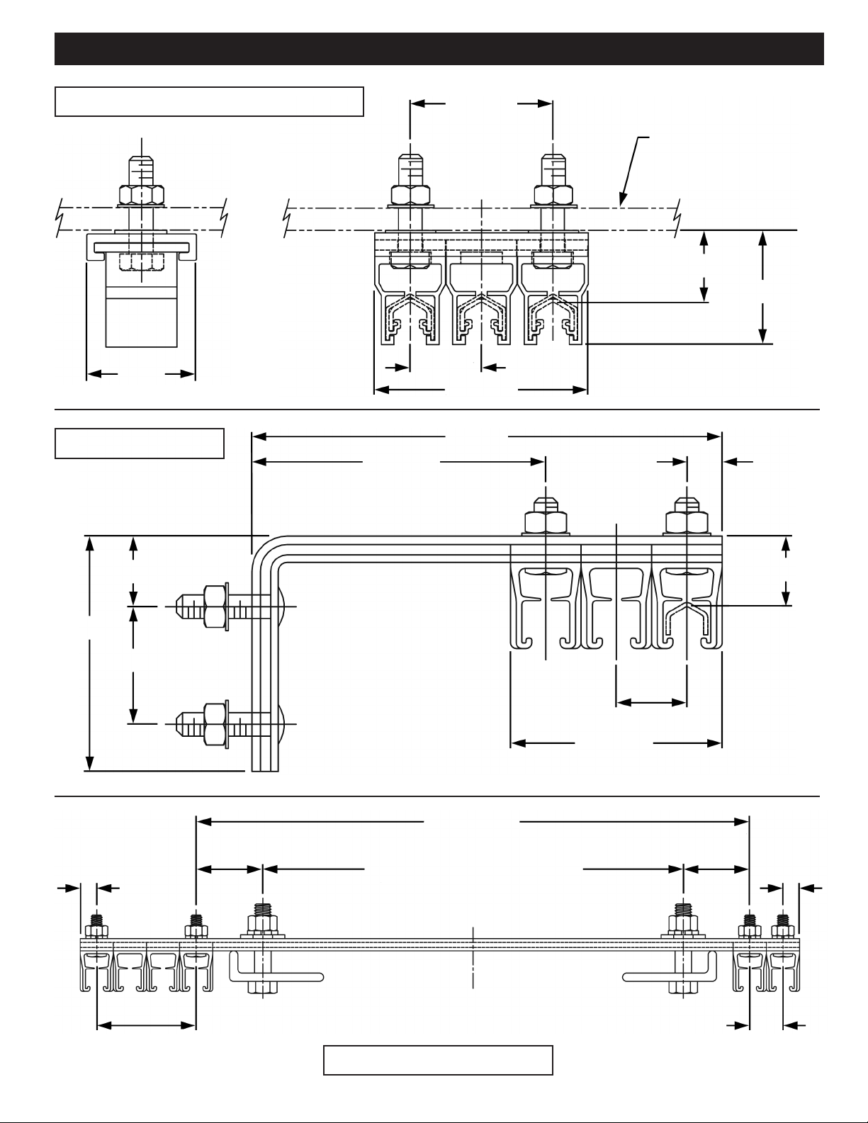
2.0 Installation
MULTI-CONDUCTOR CLAMP
1-5/32”
REF
WEB BRACKET
3-1/8” REF
1-1/2” REF
1/4” REF
Mounting Bkrt
(By Others)
Mounting Surface
3/4” REF
1-3/16” REF
3/4” REF
2-1/4” REF
5” REF
3/8” REF
2-1/2” REF
1-1/4” REF
3/8” REF
3/4” REF
1-1/2” MIN
4-1/2” MAX
12-1/2” REF
Blot Centers 3-1/2” to 9-1/2”
Beam Width Mounting 3” to 9”
3/4” REF
Contact
Surface
3/4” REF TYP
2-1/4” REF
1-1/2” MIN
4-1/2” MAX
3/8” REF
2-1/4” REF
FLANGE BRACKET
IOM CLUSTER BAR MANUAL964000.5.0
3/4” REF
5
Page 6

2.0 Installation
2.2 Splices
2.2.1 Crimp Splices
2.2.1.1 One end of each 15’ length of
Cluster Bar has a factory attached crimp joint.
2.2.1.2 To join two conductors, slide the end without a splice into the
splice of the next conductor. Butt conductors together before crimping
the joint.
2.2.1.3 To secure the splice, crimp the bottom of each side of the
splice at 1/4” and again at 3/4” from the end using the “Crimp Tool”
(see Figure 3).
2.2.1.4 Snap splice covers together and press retainer cap over top.
2.2.2 Bolted Splices
3/4”
1/4”
Figure 3
2.2.2.1 Butt conductor bar together and place bolted splice halves at
center of joint and fasten with hardware supplied (see Figure 4).
Figure 4
2.2.2 Note: Always install curved conductor first.
2.2.3 Splice Cover
2.2.3.1 Snap cover halves onto conductor enclosing the splice joint
halves. Note: The PVC conductor cover extends inside the cover halves
so that none of the conductor is exposed. A “cut-out” in the cover halves
is provided to allow for this cover.
2.2.3.2 Important: DO NOT allow the cover halves to overlap the
PVC conductor cover. Overlapping the cover may derail the collector
during operation (see Figure 5).
No Overlap of
Cover Halves
on PVC Cover
Cover Halves
Figure 5
2.3 Field Cutting
2.3.1 Square cuts are required for proper joining.
2.3.2 Deburr outside of Cluster Bar to attach splice. Deburr inside of Cluster Bar for smooth surface to guide collector shoe.
2.3.3 To allow for length of splices, cut cover 2 ¼” less than length of bar (1-1/8” from each end.)
6
IOM CLUSTER BAR MANUAL 964000.5.0
Page 7

2.0 Installation
2.4 Powerfeed
2.4.1 Locate powerfeed at a joint or end, or install
powerfeed at any point along a straight run by cutting
out 2-1/4” of the conductor cover.
2.4.2 Joint Powerfeed
(See Figures 6 & 7)
2.4.2.2 Attach a wire to terminal supplied with
Powerfeed Kit. Place powerfeed halves and terminal on
conductor bar and fasten supplied hardware.
2.4.2.3 Snap on powerfeed cover halves and press
retainer cap over top.
.60
Retainer Cap
Powerfeed Kit
Assembly
#10 AWG
Figure 6
2-3/8”
2”
2-1/4”
3-1/2”
2.4.3 End Powerfeed (See Figure 8)
2.4.3.1 For powerfeed located on end, cut back
cover 1-5/8” from end of bar. Attach wire to terminal
supplied with kit. Place powerfeed clamp halves
and terminal on conductor and fasten with hardware
supplied. Press on end cover.
2.4.3.2 If necessary, deform legs of conductor outwards
slightly to provide a press fit for plastic end cover.
#8 AWG or
#10 AWG
2.5 Anchor Clamps
2.5.1 Check installation drawings for anchor clamp locations. If no
installation drawings for anchor clamp locations, anchor as shown in
Figure 1 on Page 3.
2.5.2 Position one anchor clamp kit on each side of hanger clamp
location. Anchor clamp kit to be mounted alternately on two adjacent
hanger locations (see Figure 11).
2.5.3 Tighten screws to 35 in. lbs., so that they grab cluster bar. Do not
over-tighten.
Figure 7
Figure 8
13/16”
1”
1/2”
1-5/8”
2.5.5 On multi-conductor systems, anchor clamps will not fit on adjacent
conductors and so must be staggered (see Figure 9).
7/16”
4 Conductor System
19/32”
Figure 9
Anchor Clamp
Multi-Conductor
Hanger Clamp
2.5.4 Note: Before tightening anchor clamps, verify that expansion gaps
are properly set (see Section 2.6).
IOM CLUSTER BAR MANUAL964000.5.0
7
Page 8

2.0 Installation
7/8” REF
1-1/8” REF
75’-
1” REF 1-5/32 REF
Hanger Clamp
3-5/32” REF
2.6 Expansion Section
2.6.1 Note: Location of expansion sections is important! If no installation
drawings for location of expansion sections, install as shown in Figure 11
above. Mount expansion sections halfway between anchor points. See
installation drawing for placement.
Special Note: Expansion sections will not operate on curves.
2.6.2 Maximum distance between expansions are as follows:
Copper 96 ft.
Galvanized Steel 141 ft.
19/32”
8” MIN
18” MAX
96’-0” Copper
141’-0” Steel
Straight Run
Figure 11
Anchor Clamps
Legend
Hager Clamp
End Cover
Expansion
Anchor Clamp
Figure 10
2.6.3 Attach expansion section in same manner as conductor bar. Set
gaps according to the following chart:
Bar Temperature Gap Setting (in.)
(Degrees F) (Dim “X”. Between
ends of Conductors.)
110 3.25
100 3.36
90 3.47
80 3.58
70 3.68
60 3.80
50 3.91
40 4.02
30 4.13
7/16”
View A-A View B-B View C-C
3/16”
A B C
1-1/8”
REF
A B C
3/16”
3/4”
8
Expansion Section
Figure 12
3/16”
6’-0” Expansion Shown
9-1/2” REF
3”
1/2” REF
Gap Setting-Dim “X”
IOM CLUSTER BAR MANUAL 964000.5.0
Side View
1” REF
1” REF
Page 9

2.0 Installation
2.7 End Cap (See Figure 13)
2.7.1 If conductor bar has crimp splice, cut off splice and install
end cap.
1”
3”
5/8”
5/8”
Figure 13
2.8 Transfer Cap (See Figure 14)
2.8.1 Cut conductor bar 1” shorter than center
location of transfer cap. Prepare the end of the cluster
bar and cover in the same manner as one having a
splice installation.
2.8.2 Press transfer cap on cluster bar.
2-3/4”
1-1/8”
1”
1-1/8”
7/8”
1”
1/4” Gap Max
Figure 14
1/4-20
.20”
3/4”
Misalignment
+
1/8”
2.9 Collector Mounting Dimensions
(See Page 10)
End of Conductor
Center Location
splice see Pg: 11
Note: For top view of angled
of Transfer Cap
3.0 Maintenance
3.1 Warning: Be sure power is turned off.
3.2 Maintenance of conductor system is dependent on atmospheric conditions and frequency of use. The frequency of inspection depends on the
age of the system. A new system should be checked after one month and again the following month until a pattern of maintenance is established. For
example, a class “C” (moderate service) crane handling 50% of rated capacity with 5 to 10 lifts per hour should require maintenance approximately
every six months after the first year of service.
3.3 Collectors
3.3.1 Any accumulation of dirt or dust should be removed from the collector.
3.3.2 Replace worn collector shoes.
3.3.3 Check spring tension to provide proper pressure on every collector shoe. Replace weak springs.
3.3.4 Note: Check for free mechanical action of collector to conductor. Clean and lubricate where necessary.
3.3.5 Realign collectors vertically and horizontally to the collector mount and to the conductor. Ensure that pigtail cable does not cause misalignment of
shoe on conductor.
3.4 Conductors
3.4.1 Wipe contact surface and cover clean of grease, dust and dirt. Sufficient accumulation may cause a ground.
3.4.2 Check straightness and alignment of conductor and relieving hanger clamps to permit sliding action for free expansion of conductor.
3.4.3 Check plastic cover for wear and misalignment at joints. Replace unduly worn sections. Check vertical and horizontal alignment of conductor.
3.4.4 Check at switches, transfer points, expansion gaps, etc., for wear. Replace unduly worn parts. Tighten loose bolts.
3.4.5 Where bar has been bent or joints broken by ladders, ropes, etc., or where bar has been pitted by arcing collector, replace by cutting out with
hacksaw and clamping new section in place.
IOM CLUSTER BAR MANUAL964000.5.0
9
Page 10

2.9 Collector Mounting Dimensions
2.0 Installation
1/2” Square Bar Mount
1-1/8” Stroke
1-1/8”
Stroke
Lateral
Movement
+
1”
Staff Collector Mount
Figure 16
Figure 15
Contact Surface
9”
5-7/8”
7-3/4”
1-5/8”
7/16”
4-1/8”
7/8”
4-1/4” REF
Free Position
2-3/8” REF
Nom. Oper.
Position
11/16” REF
1/2”
Sq. Bar
Mount
2-1/2” REF
1/4” REF
1-1/8” Stroke
1-1/8”
Stroke
8” REF
7-13/16” REF
O.344 (3)
Contact Surface
1-3/16”
1-15/32”
2-3/16”
31/32”
4-1/4” REF
Free Position
2-3/8” REF
Nom. Oper.
Position
Lateral
Movement
+
1”
10
Channel Mount
Figure 17
IOM CLUSTER BAR MANUAL 964000.5.0
Page 11

4.0 Troubleshooting
4.1 Properly installed and normally inspected rigid conductor systems very seldom require extensive maintenance. When properly installed, shoe
inspection and replacement is usually all that is necessary.
Cluster Bar Conductor Troubleshooting
Problem Probable Cause Solution
Burned joints or burned cover at joints. Loose joint, excess vibration, or over tightened
hanger clamps.
Distorted cover. Too High ambient temperature, under-rated bar. Check total current draw under worst conditions.
Pitted or burned conductor. Improper shoe pressure or worn out shoe. Check collector mounting and spring pressure.
Cluster Bar Conductor Troubleshooting
Problem Probable Cause Solution
Shoes wearing unevenly. Collector not mounted directly under conductor.
Square bar is rotated out of square.
Lead wire not slacked Loosen lead wire.
Collector movement too tight. Free collector movement & lubricate.
Shoes pitted or burned Insufficient shoe pressure. Excessive bouncing
or hand-pulled trolley not stable.
De-tracking. Distorted cover or joint cover. Check condition, replace as necessary.
Tighten joint, check hanger clamps, & replace
joint cover.
Check for worn out shoe. If the above are
corrected & condition persists, install tandem
collectors.
Tighten joint, check hanger clamps, & replace
joint cover.
Check shoe pressure and mounting distance.
Excessive bouncing can be reduced with
tandem collectors. Install guide rollers on
hand pulled trolleys. Also see: Pitted or burned
conductor.
Misalignment at switched or crossovers. Re-align and re-anchor
Check switch movement.
Improperly installed. Correct misalignment.
Hanger clamp too tight making bar “snake” to
where collectors interfere with each other.
Loosen hangers so bar will slide. Tighten one
hanger in center or between each expansion
section.
IOM CLUSTER BAR MANUAL964000.5.0
11
Page 12

5.0 Typical Installations
12
IOM CLUSTER BAR MANUAL 964000.5.0
Page 13

Notes
IOM CLUSTER BAR MANUAL964000.5.0
13
Page 14

Notes
14
IOM CLUSTER BAR MANUAL 964000.5.0
Page 15

Notes
IOM CLUSTER BAR MANUAL964000.5.0
15
Page 16

www.conductix.us
© Conductix-Wampfler | 2017 | Subject to Technical Modifications Without Prior Notice
Contact us for our Global Sales Offices
16
IOM CLUSTER BAR MANUAL 964000.5.0
 Loading...