

Page 1
Installation Manual
Spring Cable Reel
BEF150 – BEF500
MAL6100-0001a-EN
www.conductix.com translated document Page 1 of 54
Page 2

Installation Manual
Spring Cable Reel
BEF150 – BEF500
MAL6100-0001a-EN
www.conductix.com translated document Page 2 of 54
Contents
1 General Notes ......................................................................................................................................... 5
1.1 About this document ................................................................................................................................... 5
1.2 Limitation of liability .................................................................................................................................... 5
1.3 Copyright .................................................................................................................................................... 5
1.4 Spare parts ................................................................................................................................................. 6
1.5 Warranty and guarantee ............................................................................................................................. 6
1.6 Customer service........................................................................................................................................ 6
2 Safety Rules ............................................................................................................................................ 7
2.1 Requirements on the personnel ................................................................................................................. 8
2.1.1 Qualifications .............................................................................................................................................. 8
2.1.2 Unauthorized personnel ............................................................................................................................. 8
2.1.3 Instruction ................................................................................................................................................... 9
2.2 Personal protective equipmen t ................................................................................................................... 9
2.3 Intended use ............................................................................................................................................. 10
2.4 Improper use ............................................................................................................................................ 10
2.5 Protective measures to be taken by the operator / user ........................................................................... 10
3 Terminology .......................................................................................................................................... 11
4 Technical Specifications ...................................................................................................................... 12
4.1 Type plate ................................................................................................................................................. 12
4.2 Technical specifications ............................................................................................................................ 12
4.3 Operating conditions ................................................................................................................................. 13
4.4 Type designation code: ............................................................................................................................ 13
4.5 Dimensional drawings .............................................................................................................................. 13
5 Functional Description ......................................................................................................................... 14
5.1 Function .................................................................................................................................................... 14
5.2 Construction ............................................................................................................................................. 14
5.3 Danger zone ............................................................................................................................................. 15
6 Transport and storage ......................................................................................................................... 16
6.1 Shipment .................................................................................................................................................. 16
Page 3

Installation Manual
Spring Cable Reel
BEF150 – BEF500
MAL6100-0001a-EN
www.conductix.com translated document Page 3 of 54
6.1.1 Safety instructions for transport ................................................................................................................ 16
6.1.2 Transport inspection ................................................................................................................................. 16
6.2 Packing ..................................................................................................................................................... 17
6.3 Storage of packed parts ........................................................................................................................... 17
7 Commissioning .................................................................................................................................... 18
7.1 Mechanical attachment ............................................................................................................................. 18
7.2 Electrical installation ................................................................................................................................. 23
7.2.1 Connecting the feed cable ........................................................................................................................ 28
7.3 Pretensioning ........................................................................................................................................... 30
7.3.1 Adjustment ............................................................................................................................................... 30
8 Operation .............................................................................................................................................. 31
8.1 Safety ....................................................................................................................................................... 31
8.2 Function .................................................................................................................................................... 31
8.3 Winding behaviour .................................................................................................................................... 31
9 Service................................................................................................................................................... 34
9.1 Safety ....................................................................................................................................................... 34
9.2 Service intervals and maintenance work .................................................................................................. 34
9.2.1 Reel .......................................................................................................................................................... 34
9.3 Replacing springs ..................................................................................................................................... 37
9.3.1 Prerequisites ............................................................................................................................................ 38
9.3.2 Series connection ..................................................................................................................................... 38
9.3.3 Parallel connection ................................................................................................................................... 42
9.4 Changing the direction of rotation ............................................................................................................. 44
9.4.1 Series connection ..................................................................................................................................... 44
9.4.2 Parallel connection ................................................................................................................................... 47
10 Troubleshooting ................................................................................................................................... 49
11 Dismantling and disposal .................................................................................................................... 50
11.1 Safety ....................................................................................................................................................... 50
11.2 Dismantling ............................................................................................................................................... 50
11.3 Disposal .................................................................................................................................................... 51
Page 4

Installation Manual
Spring Cable Reel
BEF150 – BEF500
MAL6100-0001a-EN
www.conductix.com translated document Page 4 of 54
12 Additional Documents ......................................................................................................................... 52
13 Indices ................................................................................................................................................... 53
13.1 Figures ..................................................................................................................................................... 53
13.2 Keywords .................................................................................................................................................. 54
Page 5

Installation Manual
Spring Cable Reel
BEF150 – BEF500
MAL6100-0001a-EN
www.conductix.com translated document Page 5 of 54
1 General Notes
1.1 About this document
This document makes it possible for you to work safely and efficiently with a spring cable reel.
This document is a part of the spring cable reel, and must be kept accessible to personnel at all times in its immediate vicinity.
Personnel must read this document carefully and understand it before starting any work. A basic condition for workplace safety is
the observance of all safety and handling instructions appearing below.
Local accident protection regulations and general safety regulations apply for the area of use of the spring cable reel.
The figures in this document are to be used for basic understanding, and may deviate from the actual design under some
circumstances.
In addition to this manual, the instructions located in the appendices for the individual assembled components also apply.
1.2 Limitation of liability
All information and instructions in this Installation and Operating Manual have been compiled with due regard to the standards and
regulations in force, best engineering practice, and the findings and experience we have accumulated over many years.
The manufacturer is in no way liable for damages resulting from:
Non-observance of the operating instructions
Improper use
Use by untrained personnel
Unauthorized modifications
Technical changes
Use of unauthorized replacement parts and accessories
The actual scope of delivery may differ from the explanations and illustrations described here for special variants, if additional
order options are utilized, or due to the latest technical changes.
The obligations agreed upon in the delivery agreement and our General Terms of Business apply, as do the delivery conditions of
the manufacturer and all regulations applicable at the time the contract was concluded.
All products are subject to technical modifications in the context of improvement of function and further development.
1.3 Copyright
This document is subject to copyright, and is exclusively intended for internal use by the customer.
Provision of the installation and operating instructions to third parties, duplications in any form – even in part – as well as the reuse
and/or disclosure of their content are not permitted without the written approval of the manufacturer, except for internal use by the
customer.
Violations will be subject to damages. This will not exclude additional claims.
Page 6
Installation Manual
Spring Cable Reel
BEF150 – BEF500
MAL6100-0001a-EN
www.conductix.com translated document Page 6 of 54
1.4 Spare parts
WARNING!
Safety risk due to wrong spare parts!
Wrong or faulty spare parts can result in damages, malfunctions or complete failure as well as
impair safety.
→ Use only original spare parts of the manufacturer!
→ Order replacement parts from your contracted dealer or directly from the manufacturer.
Contact data:
Conductix-Wampfler GmbH
Rheinstrasse 27 + 33
79576 Weil am Rhein - Märkt
Germany
Tel.: +49 ( 0) 7621 662-0
Fax: +49 ( 0) 7621 662-144
info.de@conductix.com
www.conductix.com
Replacement parts list:
Separate document delivered with the order. If necessary, request from Conductix-Wampfler.
Please specify the order number in your request.
1.5 Warranty and guarantee
The terms of warranty and guarantee can be found in the General Terms of Business of the manufacturer (see www.conductix.de).
1.6 Customer service
Our customer service is available for technical questions (see contact data).
Our employees are always interested in new information and experience from the field that can be valuable for the improvement of
our products.
Page 7
Installation Manual
Spring Cable Reel
BEF150 – BEF500
MAL6100-0001a-EN
www.conductix.com translated document Page 7 of 54
2 Safety Rules
Safety and hazard information is identified in this manual by the use symbols. Signal words are used to indicate the degree of
hazard in these safety instructions. Always observe safety and hazard information and work carefully to avoid accidents, bodily
harm or property damage!
DANGER!
... indicates an immediately hazardous situation, which if not avoided, may result in death or
serious injury.
DANGER!
... indicates an immediately hazardous situation due to electricity, which if not avoided, may
result in death or serious injury.
WARNING!
... indicates a possibly hazardous situation, which if not avoided, may result in death or serious
injury.
WARNING!
... indicates a possibly hazardous situation due to electricity, which if not avoided, may result
in death or serious injury.
CAUTION!
... indicates a possibly hazardous situation, which if not avoided, may result in moderate or
minor injury.
Tips and recommendations:
... refers to useful tips and recommendations as well as information for efficient and trouble-free
operation.
CAUTION!
... indicates measures that help avoid property damage.
Page 8
Installation Manual
Spring Cable Reel
BEF150 – BEF500
MAL6100-0001a-EN
www.conductix.com translated document Page 8 of 54
2.1 Requirements on the personnel
2.1.1 Qualifications
WARNING!
Injury due to insufficient qualifications!
Improper use can result in serious injury to person and property.
→ All activities may only be performed by qualified personnel.
The following qualifications have been mentioned in this manual for different areas of operation:
Trained personnel/operators
have been instructed by the operator about the tasks assigned to him/her and the possible hazards resulting from improper use.
Qualified specialists
due to their specialized training, knowledge, and experience, as well as knowledge of applicable regulations, are capable of
carrying out work assigned to them, while independently recognizing and avoiding possible risk. Personnel are considered qualified
if they have successfully concluded training, for example, as electricians, master electricians, electrical engineers, or electrical
technicians. Personnel are also considered qualified who have been employed correspondingly for several years, have been
educated in theory and practice during that time, and have whose knowledge and skills in the trade required have been tested. The
operator of the machine or system must document that the corresponding certification or other documentation of qualification are
present or have been demonstrated.
Only those persons are authorized as personnel who can be expected to perform their work reliably. People whose capacity
for reaction is influenced e.g. by drugs, alcohol, or medications are not authorized.
When selecting personnel, follow all age- and occupation-specific guidelines applicable at the location of use.
2.1.2 Unauthorized personnel
WARNING!
Danger due to unauthorized personnel !
Unauthorized personnel who do not meet the requirements described here do not
understand the danger in the working area.
→ Keep unauthorized personnel away from the working area
→ In case of doubt, address the person and direct them away from the working area
→ Stop work as long as unauthorized personnel is in the working area
Page 9
Installation Manual
Spring Cable Reel
BEF150 – BEF500
MAL6100-0001a-EN
www.conductix.com translated document Page 9 of 54
2.1.3 Instruction
Before commissioning the equipment, personnel must be instructed by the operator. For better transparency, the performance of
this instruction must be logged.
Example of instruction log:
Date Name: Type of instruction Instruction given by Signature
5 November
2010
John Doe First safety training for
personnel
Horst Müller
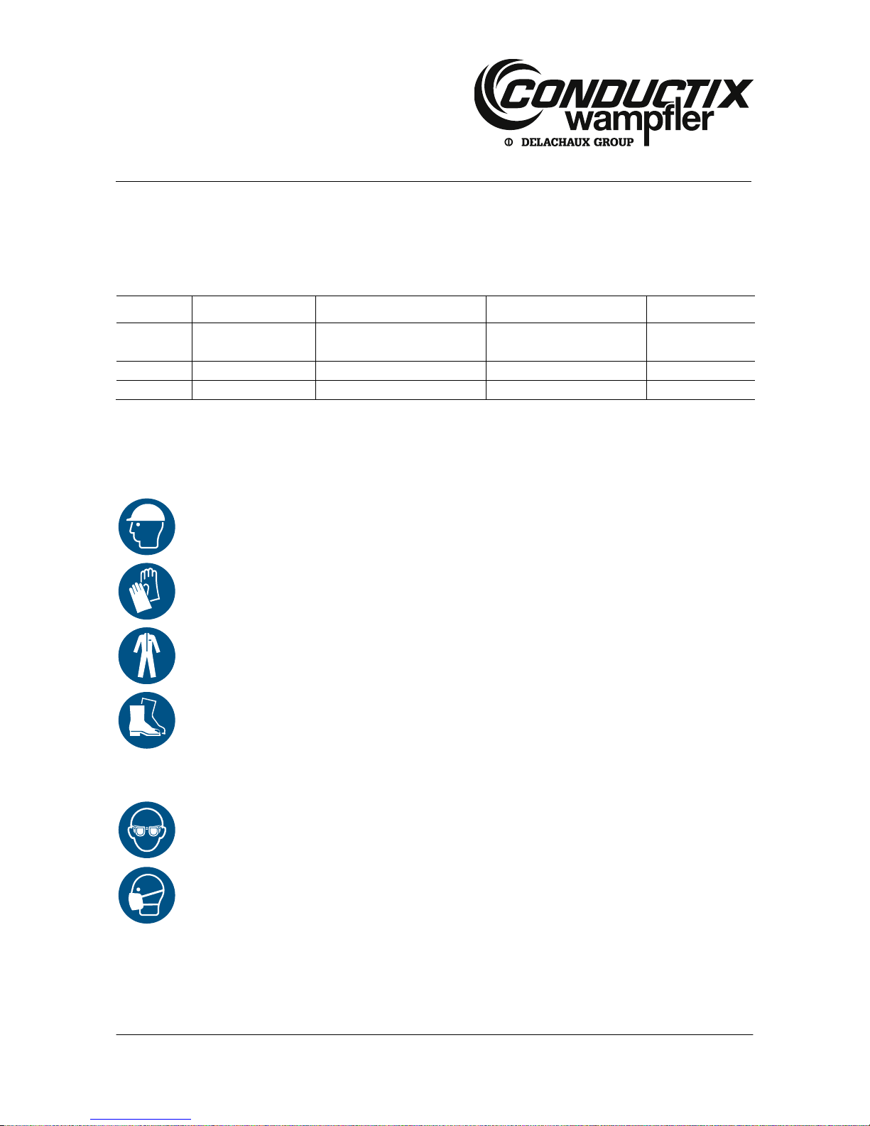
2.2 Personal protective equipment
Always wear: For all work:
Protective headgear
For protection from falling and flying parts and materials.
Protective gloves
For the protection of hands from friction, scrapes, stabbing, or deep wounds, as well as from contact with
hot surfaces.
Work safety clothing
Primarily as protection against entrapment by moving machine parts. Working clothes must fit tightly with
low resistance to tearing, close-fitting sleeves and no protruding parts.
Protective footwear
Used to protect from falling heavy parts and slipping on slippery floors.
For special tasks,
wear:
When carrying out particular tasks, special safety gear is required. The individual sections specify
this gear in detail.
Safety goggles
To protect the eye from harmful influences such as strong light, chemicals, dust, splinters, or weather.
Respirator (FFP-3 – according to country-specific requirements)
For protection against materials, particles or organisms.
Here, protection from dust resulting from the wear of the carbon brushes.
Page 10

Installation Manual
Spring Cable Reel
BEF150 – BEF500
MAL6100-0001a-EN
www.conductix.com translated document Page 10 of 54
2.3 Intended use
The spring cable reel is used for the transmission of power and data to mobile consumers with automatic winding using a coil
spring. Unwinding is not carried out manually, but rather by the mobile consumer.
Both the reel and the cable are permanently installed.
Flexible reel-capable energy or control cables are used.
The spring cable reel must always be mounted with its axis horizontal.
2.4 Improper use
Improper use is any use other than those listed in 2.3.
Use for any purpose other than or in addition to the intended use is permitted only after discussion with the manufacturer.
2.5 Protective measures to be taken by the operator / user
The spring cable reel is used in commercial/industrial areas. The operator of the spring cable reel is therefore subject to legal
regulations concerning workplace safety. In addition to the safety instructions in this manual, all valid safety, accident protection
and environmental protection regulations applicable for the place of operation of the spring cable reel apply.
This particularly includes:
The operator must be informed of applicable workplace safety regulations and carry out a risk assessment to detect additional
dangers resulting from the specific working conditions in the place of operation of the spring cable reel. This must be
implemented in the form of operating instructions for the operation of the spring cable reel.
For the entire period of use of the spring cable reel, the operator must check whether the operating instructions prepared
correspond to the current state of regulations, and update the operating instructions as needed.
The operator must clearly regulate and determine responsibilities for installation, operation, troubleshooting, and maintenance.
The operator must ensure that all employees involved with the spring cable reel have read and understood this manual. The
operator must furthermore train personnel at regular intervals and inform them of hazards.
The operator must provide personnel with all required safety gear.
The operator is furthermore responsible for ensuring that the spring cable reel is always in a technically trouble-free condition. The
following thus applies:
The operator must ensure that the service intervals described in this manual are observed.
The operator must regularly have all safety systems inspected for functionality and completeness (once yearly if possible, but
at least as often as required by applicable national regulations).
If the device or system has been modified, the safety systems must be inspected again and adapted to the changed
conditions in such a way that the device or system is safe again.
Page 11
Installation Manual
Spring Cable Reel
BEF150 – BEF500
MAL6100-0001a-EN
www.conductix.com translated document Page 11 of 54
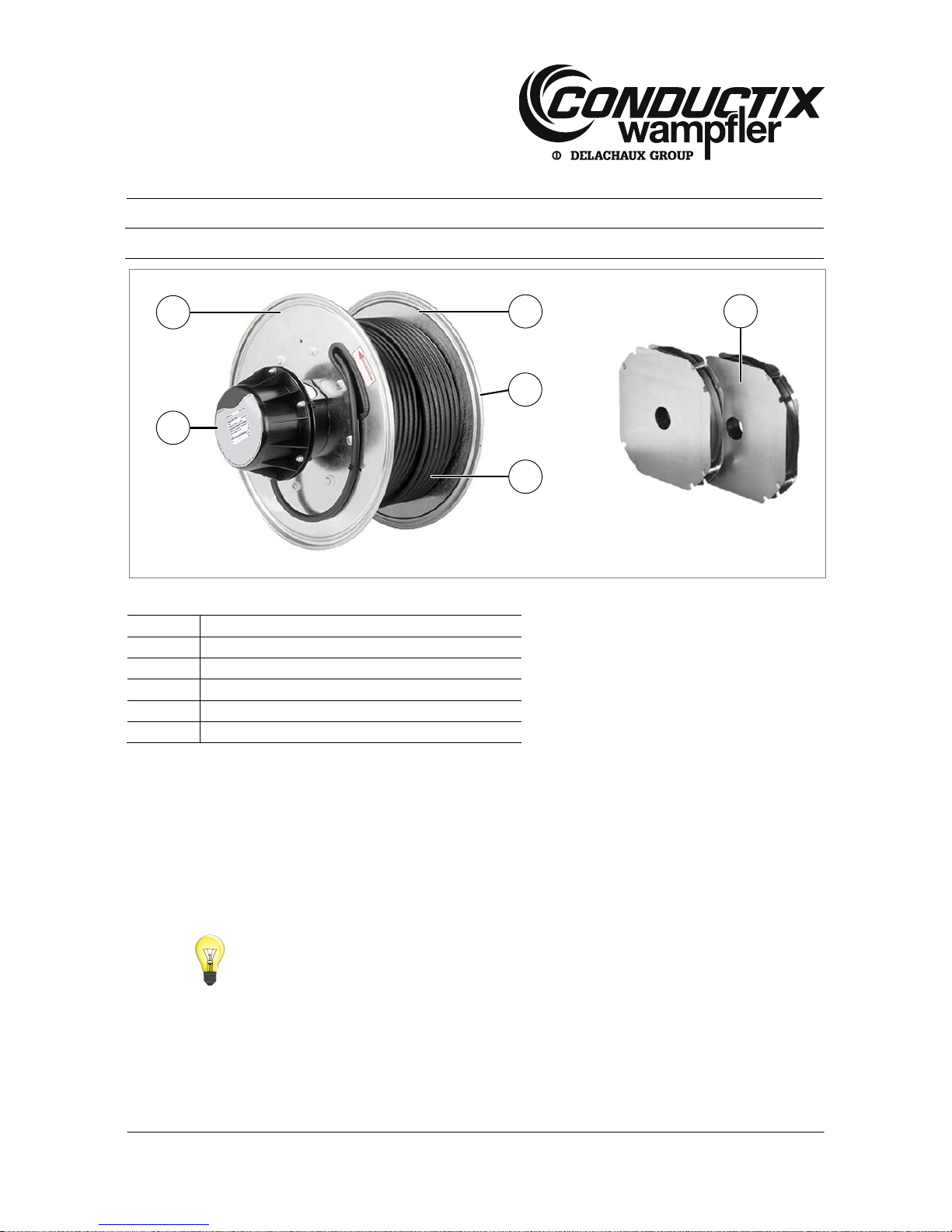
3 Terminology
Fig. 1 Main assemblies of the spring cable reel
Item
Description
1
End flange, both sides
2
Slip ring body, housing with type plate
3
Reel-capable cable (optional)
4
Coil spring with protective guard
5
Fastening flange
Power spring
Coil spring without coiling gap, with large energy storage capacity.
Spring nominal values
n
v
: pre-loading rotations
n
a
: work rotations
n
R
: reserve rotations
n
Bl
: rotations until block = nv + na + n
R
Winding direction: left by default (as seen from slip ring body housing: counter-clockwise)
Protective guard
Sheet metal housing in which the drive springs are installed to protect service personnel from injury.
Protection class
Protection against contact and against penetration of foreign bodies and water (see EN 60529; DIN VDE 0470-1).
3
1 2 1
4
5
Page 12

Installation Manual
Spring Cable Reel
BEF150 – BEF500
MAL6100-0001a-EN
www.conductix.com translated document Page 12 of 54
4 Technical Specifications
4.1 Type plate
The type plate is located on the top part of the slip ring body housing (see Fig. 2).
The technical specifications can be read off the type plate (depending on the model and variant).
Fig. 2 Type plate
4.2 Technical specifications
Example:
Data Value
Model
BEF 325524 – 1824/04ML – 2MB (T)H/L
Spring rotations
depending on the cable take-off
Max. total
44
Pretension nv
20
Reserve nr
4
Year of construction
2010
Slip ring body
1824 21+PE+2xS/04ML
Electrical current
21x25A+PE+4x20mA
Voltage
690 V/10 V
Protection class
IP65
Winding length
24 m
Order number
123456xxx
Page 13
Installation Manual
Spring Cable Reel
BEF150 – BEF500
MAL6100-0001a-EN
www.conductix.com translated document Page 13 of 54
4.3 Operating conditions
Requirements for the working environment:
Designation Value Notes
Winding behaviour
0.3 m/s2
Max. acceleration
Temperature range
-20 to 40 °C
Operation in air - Maritime climate possible for short periods, mild chemical
atmosphere, not in radioactive environment
Other values may be possible upon request.
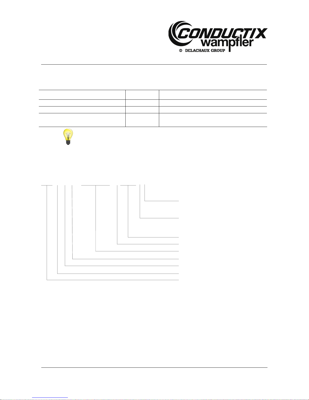
4.4 Type designation code:
The type designation code includes the specification and the design features of the spring cable reel.
BEF 32 55 24 - 1824/04ML - 2 MB(T) H/L
Uncoiling direction
L = left
R = right
Circuit
H = series
- = parallel
Spring type
Number of springs
Slip ring body
Winding width
Outside diameter
Winding diameter
Model series
4.5 Dimensional drawings
See separate documentation for dimensional drawings and dimensional tables.
Page 14
Installation Manual
Spring Cable Reel
BEF150 – BEF500
MAL6100-0001a-EN
www.conductix.com translated document Page 14 of 54
5 Functional Description
5.1 Function
The spring cable reel is designed for the automatic coiling cables for mobile consumers. The cable is wound using pretensioned
coil springs that are installed inside the body of the reel.
The reel is equipped with a fastening flange that is connected to the fixed axis by two threaded pins.
Unwinding is automatic and is implemented on site.
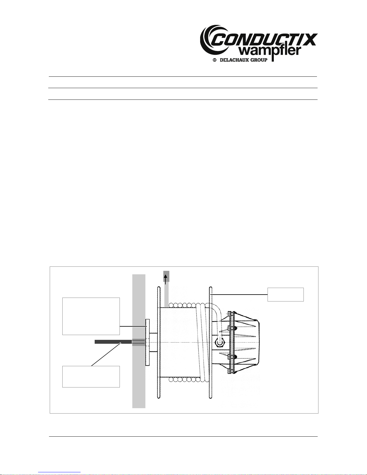
5.2 Construction
The reel is ball bearing mounted.
The reel body consists of a solid screwed plate structure (galvanised plate). Inside the reel body there is the spring chamber with
the spring set.
The drive springs and ball bearings are lubricated with a special grease for the temperature range from -55 °C to +100 °C.
Against the flange side is the chamber in which the slip ring body is housed. This area is covered by a two-part plastic or steel hub
(protection classes: IP54 steel, IP65 plastic).
The metric entry for the reel-capable cable (cable collar) is located in the lower part of the hub.
The slip ring of the slip ring body is screwed onto the fixed axis.
The current collector part is connected to the rotating reel body.
Fig. 3 Reel mount
fixed
Reel mount and cable
entry provided on site
rotating
Cable feed through the
wall
Page 15
Installation Manual
Spring Cable Reel
BEF150 – BEF500
MAL6100-0001a-EN
www.conductix.com translated document Page 15 of 54
5.3 Danger zone
When using spring cable reels, there are two main danger zones to take into consideration:
Rotating reel
During operation, the reel cable is unrolled and/or rolled back in under spring tension. The reel body turns during these actions.
WARNING!
Danger zone: rotating parts!
Danger of injury from rotating machine parts!
→ During operation, keep a safe distance from the rotating reel body!
Reel cable
During operation, the reel cable is unrolled and/or rolled back in under spring tension. The cable represents an obstacle. Increased
alertness is required in this area.
DANGER!
Danger zone: reel cable!
Danger of stumbling resulting in injury due to moving exposed cables!
→ During operation, keep a safe distance from the reel cable!
DANGER!
Danger zone: reel cable!
While the reel cable is being wound by spring tension, there is a danger of
entanglement/crushing.
→ Increased alertness is required in the winding area!
DANGER!
Danger zone: reel cable!
Danger of crushing and entanglement resulting in injury due to cables being reeled in!
→ During winding, keep a safe distance from the rotating reel body!
Page 16
Installation Manual
Spring Cable Reel
BEF150 – BEF500
MAL6100-0001a-EN
www.conductix.com translated document Page 16 of 54
6 Transport and storage
6.1 Shipment
6.1.1 Safety instructions f or transport
WARNING!
Danger of death due to hanging loads!
Falling parts or those swinging out of control can lead to severe injury or even death.
→ Never step under hanging loads
→ Only use the attachment points provided; do not fasten lifting accessories to projecting
machine parts or components built onto eyes.
→ Be sure the connection elements are firmly seated
→ Use only authorized lifting accessories and connection elements with sufficient load capacity
→ Do not use torn or worn ropes or straps, but rather replace them with new ones
→ Do not attach ropes or straps to sharp corners and edges, and do not knot or twist them
→ Move loads only under supervision
→ Set down the load when leaving the workplace
WARNING!
Possible damage from improper transport!
Improper transport can result in substantial property damage.
→ Act with care when unloading packaged parts upon delivery as well as during internal
transport, and observe the symbols and the hazard information on the packaging
→ Use only the attachment points provided
→ Wait to remove packaging material until just before installation
6.1.2 Transport inspection
Check the delivery for completeness and transport damage immediately upon receipt.
Procedure in case of externally detectable transport damage:
→ Do not accept delivery, or accept it only with reservations
→ Note the scope of damage on the transport documents or on the transporter's delivery note
→ File a complaint
CAUTION!
Damage compensation claims may only be made within the applicable claim periods.
→ Claim every defect as soon as the defect is detected.
Page 17
Installation Manual
Spring Cable Reel
BEF150 – BEF500
MAL6100-0001a-EN
www.conductix.com translated document Page 17 of 54
6.2 Packing
The individual packaged parts must be packed according to the transport conditions to be expected. Only environmentally friendly
materials have been used for packaging.
The packaging must protect the individual components from transport damages, corrosion, and other damage until installation.
Do not destroy the packaging and remove it only just before installation.
Handling packaging materials:
Dispose of packaging material according to valid legal regulations and local guidelines.
CAUTION!
Environmental damage due to improper disposal!
Packaging material is a valuable resource and can be reused, processed or recycled in many
cases.
→ Dispose of packaging materials in an environmentally appropriate manner
→ Comply with locally applicable disposal guidelines; if necessary, engage a specialist with
disposal
6.3 Storage of packed parts
Store packed parts under the following conditions:
Do not store outdoors
Store in a dry, dust-free place
Do not expose to aggressive media
Protect from direct sunlight
Avoid mechanical vibrations
Storage temperature: 15-35 °C
Relative humidity: max. 60 %
When storing for more than 3 months, check the general condition of all parts and the packaging at regular intervals. If
necessary, add or replace the preservative
CAUTION!
Under some circumstances, there may be instructions for storage on the packed parts which
go beyond the requirements listed here.
→ Follow them appropriately
Page 18

Installation Manual
Spring Cable Reel
BEF150 – BEF500
MAL6100-0001a-EN
www.conductix.com translated document Page 18 of 54
7 Commissioning
CAUTION!
Installation
→ During electrical installation of the reel, note whether it was delivered with or without the
wound cable.
CAUTION!
Commissioning may only be carried out by an electrician.
7.1 Mechanical attachment
The unit must be mechanically attached to a stable connection point with adequate load capacity. Beams, massive masonry or
fastening blocks (accessories) may be used as connection points.
Use the three drilling templates depending on the flange size:
Flange size
Drilling templates
61-F001-0039
BEF150
61-F001-0055
BEF185 – 325
61-F001-0056
BEF400 + 500
The three drilling templates for cutting out are on the following pages.
CAUTION!
Check the drilling templates!
If you use the drilling templates shown below, then please note the following:
→ Do not scale the document while creating and printing the PDF! In the print menu, select the
function "No scaling"
→ Before cutting the templates out, check their dimensions!
Page 19

Installation Manual
Spring Cable Reel
BEF150 – BEF500
MAL6100-0001a-EN
www.conductix.com translated document Page 19 of 54
Fig. 4 Drilling template BEF150/61-F001-0039
Page 20

Installation Manual
Spring Cable Reel
BEF150 – BEF500
MAL6100-0001a-EN
www.conductix.com translated document Page 20 of 54
Fig. 5 Drilling template BEF185 – 325/61-F001-0055
Page 21

Installation Manual
Spring Cable Reel
BEF150 – BEF500
MAL6100-0001a-EN
www.conductix.com translated document Page 21 of 54
Fig. 6 Drilling template BEF400 – 500/61-F001-0056
Page 22

Installation Manual
Spring Cable Reel
BEF150 – BEF500
MAL6100-0001a-EN
www.conductix.com translated document Page 22 of 54
During installation, please note:
→ The axis of the spring cable reel must always be positioned horizontally.
→ The screw attachment surface must be flat.
Fig. 7 Fastening flange and reel axis
CAUTION!
Reel attachment
The threaded pin for attaching the flange (detail A, Fig. 7) must engage in the depression in
the axis. The threaded pin is secured at the factory against loosening.
→ Do not loosen the threaded pin, secure it again when it is screwed back in
→ Be sure the reel is mounted at right angles to the cable take-off!
Use the following screw sizes to match the drilling template:
Dimension/drilling template Screw size Tightening torque, match to screwing surface
BEF150/61-F001-0039 M8 (4x) 25 Nm
BEF185-135/61-F001-0055 M12 (4x) 85 Nm
BEF400-500/61-F001-0056 M16 (4x) 210 Nm
Leave the following dimensions for the cable entry depending on the conductor cross-section/dimensions:
Size Connection hole Max. cable diameter
BEF150
M20x1.5
10 mm
BEF185-225
M25x1.5
20 mm
BEF265-325
M32x1.5
25 mm
BEF400-500
M40x1.5
35 mm
Axis horizontal
Screw attachment
surface flat
Page 23

Installation Manual
Spring Cable Reel
BEF150 – BEF500
MAL6100-0001a-EN
www.conductix.com translated document Page 23 of 54
7.2 Electrical installation
Connecting the reel cable
CAUTION!
Attach tension relief!
→ To avoid damage to the cables, always provide sufficient tension relief
WARNING!
Note before turning on!
→ Before the device or system is started, test the insulation resistance according to locally
applicable technical standards, directives, and law
→ Carry out all locally required electrical testing according to applicable regulations
WARNING!
Danger of death by electrocution!
Contact with components carrying electrical power can lead to death or severe injury by
electrocution. Danger of injury due to shock reactions, falling, or being thrown away due to
electrical shock.
→ Before starting electrical connection work, disconnect all relevant cables from power and
secure the device or system against being turned back on
→ Follow the five safety rules!
→ Earth the device on the earthing connection (PE) of the slip ring body
Carry out electrical installation after mechanical attachment is complete.
The connections for earth, electrical feed and the reel cable are in the slip ring body.
Page 24

Installation Manual
Spring Cable Reel
BEF150 – BEF500
MAL6100-0001a-EN
www.conductix.com translated document Page 24 of 54
Fig. 8 Cable connections on the slip ring body
Connecting the reel cable:
→ Remove slip ring body hub.
→ Guide the mobile cable (= reel cable) through the slot in the outer round plate and into the collar in the lower part of the hub in
the slip ring body.
→ Connect the reel cable to the current collectors of the slip ring body.
→ The cable may not contact the slip ring body within the slip ring body housing!
→ Tighten the cable collars to relieve tension.
Overview of current collector variants:
Current collectors Connection material to be used
Type 45
Blade receptacle 6 3x0.5 (see Fig. 9)
Type 13
M5 cable shoe (see Fig. 10)
Type 15
M6 cable shoe (see Fig. 10)
Type 16
M8 cable shoe (see Fig. 11)
Type 18
M4 cable shoe (see Fig. 12) or insulated blade receptacle 6 3x0.5
Type 19
M8 cable shoe (see Fig. 11)
CAUTION!
Terminal diagram
→ Follow the attached terminal diagram for connection work.
Cable connections,
earth, feed
Cable connections,
reel cable
Page 25

Installation Manual
Spring Cable Reel
BEF150 – BEF500
MAL6100-0001a-EN
www.conductix.com translated document Page 25 of 54
The current collector variants:
Fig. 9 Type 45 current collector connection
Fig. 10 Types 13, 15 current collector connection
Page 26

Installation Manual
Spring Cable Reel
BEF150 – BEF500
MAL6100-0001a-EN
www.conductix.com translated document Page 26 of 54
Fig. 11 Types 16, 19 current collector connection
Fig. 12 Type 18 current collector connection
Page 27

Installation Manual
Spring Cable Reel
BEF150 – BEF500
MAL6100-0001a-EN
www.conductix.com translated document Page 27 of 54
Fig. 13 Types 18 current collector connection with blade receptacle
→ Wind the reel cable by hand without twisting it, and tie the cable end onto the reel.
→ Pretension the reel with n
v
turns (see section 4.1) in the take-off direction and secure against rewinding.
→ Release the end of the cable and unwind as much cable by hand (without turning the reel) as needed to reach the attachment
point that is the shortest distance away.
→ Connect the cable end.
→ Remove the protection against unwinding and release the spring tension carefully.
→ Check whether unwinding works (check the unwinding function).
DANGER!
Danger of injury if cable breaks!
If the spring set is tightened until it blocks, the cable can tear off (cable break) because
excessive forces are exerted on the cable. This can lead to extreme property damage and
injury or even death!
→ During installation, please be sure that at least two reserve windings are left when the
mobile attachment point is at its maximum distance (complete cable unwinding)
→ Never wind the spring set to its blocking point
Page 28

Installation Manual
Spring Cable Reel
BEF150 – BEF500
MAL6100-0001a-EN
www.conductix.com translated document Page 28 of 54
7.2.1 Connecting the feed cable
WARNING!
Danger of death by electrocution!
Contact with components carrying electrical power can lead to death or severe injury by
electrocution. Danger of injury due to shock reactions, falling, or being thrown away due to
electrical shock.
→ Before starting electrical connection work, disconnect all relevant cables from power and
secure the device or system against being turned back on
→ Follow the five safety rules!
→ Earth the device on the earthing connection (PE) of the slip ring body
→ Unscrew and remove the cap of the slip ring body.
→ Guide the feed cable and earthing cable through the cable entry (masonry, beams, etc.), the reel flange and the reel axis to
the slip ring body.
CAUTION!
Terminal diagram
→ Follow the attached terminal diagram for connection work.
→ Connect the cables.
→ Check all connections for secure, firm seating.
→ Replace the slip ring body cap and screw it back into place.
→ Wind the reel cable by hand without twisting and tie the cable end down.
The connections to the slip ring variants are shown in the illustrations below:
Slip ring Connection material to be used
Type 45 None needed, since the only terminal board variant possible has mantle terminals
Type 13 M6 cable shoe
Type 15
M8 cable shoe
Type 16 M8 cable shoe
Type 18
None for terminal board variants with mantle terminals; M5 cable shoe for direct wiring
Type 19
M8 cable shoe
Page 29

Installation Manual
Spring Cable Reel
BEF150 – BEF500
MAL6100-0001a-EN
www.conductix.com translated document Page 29 of 54
Fig. 14 Type 13, connection plate with terminals
Fig. 15 Type 18, connection plate with terminals
Fig. 16 Type 45, terminal board with terminals
Page 30

Installation Manual
Spring Cable Reel
BEF150 – BEF500
MAL6100-0001a-EN
www.conductix.com translated document Page 30 of 54
7.3 Pretensioning
7.3.1 Adjustment
Connecting the reel
DANGER!
Danger of injury from pretensioned drive springs!
If the spring tension is released suddenly, the reel can turn at high speed in an uncontrolled
manner. This can cause impacts, crushing, shearing and other severe injuries.
→ Secure the cable against unwinding while pretensioning
→ Always avoid sudden release of the spring tension
→ Tie the free end of the cable to the reel.
→ Move the mobile attachment point to its closest distance.
→ Pretension the reel with n
v
turns (see the type plate) in the take-off direction, and hold it fast.
→ Release the end of the mobile cable and manually unwind enough cable to reach the attachment point.
Do not turn the reel, but rather unwind the cable from the reel!
→ Connect the cable end to the attachment point and release the reel.
Test run:
→ Remove any obstacles that could lead to collisions with the reel or the cable.
→ At low speed and with visual contact, carry out a test run to check that the cable can unwind without problems.
WARNING!
Danger of injury if the cable breaks!
An emergency stop must be possible at any time throughout the unwinding process!
→ Count the working turns of the reel and compare them with the specifications on the type plate.
→ If the specified number of working turns (see type plate) has been exceeded, immediately stop the unwinding process and
contact Conductix-Wampfler.
→ Check the orientation of the cable on the reel: The cable must overlap itself in an orderly manner when wound.
Page 31

Installation Manual
Spring Cable Reel
BEF150 – BEF500
MAL6100-0001a-EN
www.conductix.com translated document Page 31 of 54
8 Operation
8.1 Safety
WARNING
Danger of injury due to improper operation!
Improper operation can result in serious injury to person and property.
→ Carry out all operating steps according to the specifications of these instructions.
→ Before starting work, be sure that all covers and safety systems are installed and working
property.
→ Never disable the safety systems during operation.
→
Maintain order and cleanliness in the working area! Loosely stacked or scattered components
and tools are a source of accidents.
WARNING
Danger for unauthorized personnel!
Personnel who do not meet the requirements described here do not understand the danger in
the working area.
→ Keep unauthorized personnel away from the working area
→ In case of doubt, address the person and direct them away from the working area
→ Stop work as long as unauthorized personnel is in the working area
Personnel:
Only instructed personnel may operate the device or system.
Personal protective clothing (must be worn for all work):
Work safety clothing
Protective footwear
8.2 Function
After proper mechanical and electrical installation, the spring cable reel can be used.
Depending on the specific application, cable supports or rollers may need to be designed and installed. For short take-off lengths,
free cable-take-off is possible.
In the case of vertical take-off either upwards or downwards, additional weight (due to the cable's own weight or for example control
panels or the like) or opposing weights (from above) must also be taken into consideration.
The wound cable is unwound against the pretensioned coil springs, in either the horizontal or the vertical direction.
Be sure that the cable is always wound and unwound at a 90° angle to the reel axis.
8.3 Winding behaviour
While setting up the spring cable reel, be sure that the fixed point is located within the winding width (dimension "b" in Fig. 17) in
order to achieve optimum winding behaviour. The deflection angle of the cable may never be > 3°-5° in any position, since
otherwise there will be irregularities during winding and excessive axial force will result.
Page 32

Installation Manual
Spring Cable Reel
BEF150 – BEF500
MAL6100-0001a-EN
www.conductix.com translated document Page 32 of 54
The cable can only be properly wound if the maximum permissible angle is observed!
Fig. 17 Optimum winding behaviour
Page 33

Installation Manual
Spring Cable Reel
BEF150 – BEF500
MAL6100-0001a-EN
www.conductix.com translated document Page 33 of 54
Fig. 18 Deflection
CAUTION!
Do not twist cable during operation!
The cable must not be installed in such a way that it can twist around its lengthwise axis. This
will destroy the cable.
→ Check the winding behaviour of the reel at regular, short intervals
→ Replace defective cables and set up the application in such a way that cables only wind
straight
Correct arrangement of the cable reel and the cable fixed
point.
The maximum permissible angle still
applies when guide rollers are used. If
necessary, increase the distance from
the guide rollers to the cable reel.
Page 34

Installation Manual
Spring Cable Reel
BEF150 – BEF500
MAL6100-0001a-EN
www.conductix.com translated document Page 34 of 54
9 Service
9.1 Safety
WARNING!
Danger of death by electrocution!
Contact with components carrying electrical power can lead to death or severe injury by
electrocution. Danger of injury due to shock reactions, falling, or being thrown away due to
electrical shock.
→ Before starting electrical connection work, disconnect all relevant cables from power and
secure the device or system against being turned back on
→ Follow the five safety rules!
→ Earth the device on the earthing connection (PE) of the slip ring body
9.2 Service intervals and maintenance work
Have an electrician carry out an inspection after no more than one year. If the strain is unusually high, the electrician must be
called earlier.
9.2.1 Reel
→ Check all bolts and nuts for firm seating, since all reels are assembled from individual parts.
→ Check all rubber seals and cable collars for tightness and/or damage.
→ If necessary, replace rubber seals or cable collars.
Flange
→ Check the connection between the flange and axis for firm seating.
Clean the slip ring body
Protective equipment needed:
CAUTION!
Danger of sensitization, mucous membrane irritation and respiratory disease due to dust!
Abrasion residue from the carbon brushes collects in the slip ring body. This dust is very fine and is
a health hazard.
→ During cleaning, wear personal protective equipment:
• Safety goggles
• Dust mask, class FFP3
→ Do not blow out dust with compressed air but rather vacuum it away. The vacuum cleaner
must be equipped with a class H fine filter
→ Do not eat, drink or smoke during work!
Page 35

Installation Manual
Spring Cable Reel
BEF150 – BEF500
MAL6100-0001a-EN
www.conductix.com translated document Page 35 of 54
CAUTION!
Do not clean the ring surface with chemical agents. The ring surface can be destroyed by
chemical agents.
→ Clean dust deposits and abrasion residue from the slip ring body.
→ Check the ring surface; grind it smooth if necessary.
→ Check all wires for firm connections and damage to insulation.
Replace current collector:
Conductix-Wampfler uses different types of current collectors!
→ Disconnect all cables from power and secure against being turned back on.
→ Unscrew and remove the housing of the slip ring body.
→ Unscrew the cables and wires from the rings and current collectors.
→ Unscrew the wires from the current collectors that will be replaced.
→ Insert and bolt down the new current collector.
→ Reconnect all wires and check for firm seating.
→ Replace the housing of the slip ring body and screw it in place.
Overview of current collector variants with rings:
Fig. 19 Type 13, current collector with slip ring
Fig. 20 Type 15, current collector with slip ring
Page 36

Installation Manual
Spring Cable Reel
BEF150 – BEF500
MAL6100-0001a-EN
www.conductix.com translated document Page 36 of 54
Fig. 21 Type 16, current collector with slip ring
Fig. 22 Type 18 current collector, assembly/disassembly and slip ring
Fig. 23 Type 19, current collector with slip ring
1
2
1
2
Page 37

Installation Manual
Spring Cable Reel
BEF150 – BEF500
MAL6100-0001a-EN
www.conductix.com translated document Page 37 of 54
Fig. 24 Type 45/1 + 45/3: Current collector with slip ring and wire
Fig. 25 Type 45/2, current collector with slip ring and wire
Cables:
→ Check that cables are installed without twisting. If necessary, loosen the cable and install it so that it is not twisted.
→ Check state. Replace damaged cables.
→ Check cable collars.
→ The cables in the slip ring body housing must be laid in such a way that the current collectors can move freely.
9.3 Replacing springs
Replacement parts for reels and slip ring bodies can be found in the replacement parts list you received with your reel (see section
1.4).
Page 38

Installation Manual
Spring Cable Reel
BEF150 – BEF500
MAL6100-0001a-EN
www.conductix.com translated document Page 38 of 54
DANGER!
Danger of fatal injury from pretensioned drive springs!
The drive springs are installed in protective metal housings for protection from injury. If the
protective housings are opened, then the drive springs (coils of spring steel) can be released
from the protective housing in an uncontrolled manner. This can cause severe cuts and
impact injuries that could even be fatal.
→ Do not open the protective housing!
→ Replace springs only as a complete unit with the protective housings!
DANGER!
Danger of death due to hanging loads!
When lifting loads, there is a danger of death from falling parts or those swinging out of
control.
→ Never step under hanging loads
→ Follow the specifications for the attachment points provided
9.3.1 Prerequisites
Disconnect all cables from power and secure against being turned back on.
Disconnect the mobile cable from the feed point (= attachment point) and wind it onto the reel body. Release the springs
slowly and completely during this process.
Remove the mobile cable from the reel.
Unscrew and remove the housing of the slip ring body.
Disconnect the fixed feed cable from the slip ring body and pull it out through the central axis.
The complete cable must be removed.
Remove the complete reel from the device.
9.3.2 Series connection
Spring designation, e.g.: 2DH (T) H or 2UA (T)H [H for series connection]
9.3.2.1 Dismantling
→ Loosen the threaded pin [1] of the fastening flange.
→ Pull off the flange [2], V-ring [3] and spacer [4].
Page 39

Installation Manual
Spring Cable Reel
BEF150 – BEF500
MAL6100-0001a-EN
www.conductix.com translated document Page 39 of 54
"Left" take-off:
Fig. 26 Changing springs, series connection with left take-off
BEF185 – BEF500
→ On the flange side, loosen the hex nuts [10] of the protective housing bolts and the hex nuts [5] of the connection between the
end flange and the reel body.
→ Remove the silicone joint between the end flange and the reel body, then carefully pull off the end flange with its bearing
flange [6].
→ Loosen the threaded pin of the spacer [7] and pull it off the axis.
→ Carefully lift out the protective housing [9, 11].
BEF150
→ On the flange side, loosen the cylinder screws [5] of the connection between the end flange and the reel body.
→ Remove the silicone joint between the end flange [6] and the reel body [0], then carefully pull off the end flange with its
bearing flange.
→ Loosen the threaded pin of the spacer [10] and pull it off the axis.
→ Carefully lift out the protective housing [7, 8].
CAUTION!
The towing part protective housing is suspended in the guide groove of the reel body and
the first spring [7] on the flange side.
BEF185 – BEF500
BEF150
Page 40

Installation Manual
Spring Cable Reel
BEF150 – BEF500
MAL6100-0001a-EN
www.conductix.com translated document Page 40 of 54
"Right" take-off:
Fig. 27 Changing springs, series connection with right take-off
BEF185 – BEF500
→ On the flange side, loosen the hex screws [5] of the connection between the end flange and the reel body.
→ Remove the silicone joint between the end flange and the reel body, then carefully pull off the end flange with its bearing
flange [6].
→ Loosen the threaded pin of the spacer [7] and pull it off the axis.
→ Loosen the threaded pin of the fixed spring nut [8] and take it out.
→ Lift the protective housing(s) [9] out with the spring nut.
→ Loosen the hex nuts [10] of the fixed protective housing [11] on the outside of the end flange on the slip ring body side.
→ Carefully lift out the protective housing [11].
BEF150
→ On the flange side, loosen the cylinder screws [5] of the connection between the end flange and the reel body.
→ Remove the silicone joint between the end flange [6] and the reel body [13], then carefully pull off the end flange with its
bearing flange.
→ Loosen the threaded pin [11] of the slip ring body and carefully pull the axis out until the threaded pins [9] of the spring nut [12]
are accessible.
→ Loosen the threaded pins of the spacer [10] and the spring nut, and take them out.
→ Carefully lift out the protective housing [7, 8].
CAUTION!
The towing part protective housing [8] is suspended in the guide groove of the reel body
and is held in place by a plastic profile.
→ Take out the plastic profile and then the protective housing [8].
BEF185 – BEF500
BEF150
Page 41

Installation Manual
Spring Cable Reel
BEF150 – BEF500
MAL6100-0001a-EN
www.conductix.com translated document Page 41 of 54
9.3.2.2 Installation
Even the unbroken springs should be replaced, since they can soon be expected to suffer from fatigue.
→ Before reassembly, coat the spring nuts and their holes generously with acid-free, elastic grease.
Recommended grease: Klüber CENTOPLEX 2 DL
→ Clean all parts that will be reused.
→ Assembly proceeds in the reverse sequence.
→ Secure the threaded pin [1] against loosening.
→ Follow the starting instructions (see Chapter 7).
WARNING!
Danger of death by electrocution!
→ Earth the device on the earthing connection (PE) of the slip ring body!
Page 42

Installation Manual
Spring Cable Reel
BEF150 – BEF500
MAL6100-0001a-EN
www.conductix.com translated document Page 42 of 54
9.3.3 Parallel connection
Spring designation, e.g.: 2DH (T) or 2UA (T)
Fig. 28 Changing springs, parallel connection
9.3.3.1 Dismantling
→ Loosen the threaded pin [1] of the fastening flange.
→ Pull off the flange [2], V-ring [3] and spacer [4].
BEF185 – BEF500
→ On the flange side, loosen the hex nuts [5] of the parallel bolts and the hex nuts [6] of the connection between the end flange
and the reel body.
→ Remove the silicone joint between the end flange and the reel body, then carefully pull off the end flange with its bearing
flange [7].
→ Pull the spacers [8] off the parallel bolts.
→ Carefully lift out the protective housing(s) [9].
BEF150
→ On the flange side, loosen the cylinder screws [5] of the connection between the end flange and the reel body.
→ Remove the silicone joint between the end flange [6] and the reel body [8].
→ Carefully pull off the end flange with its bearing flange.
→ Carefully lift out the protective housing and springs [7].
CAUTION!
All protective housings are towing part housings and are guided by a guide bar inside the reel
body!
BEF185 – BEF500
BEF150
Page 43

Installation Manual
Spring Cable Reel
BEF150 – BEF500
MAL6100-0001a-EN
www.conductix.com translated document Page 43 of 54
9.3.3.2 Installation
Even the unbroken springs should be replaced, since they can soon be expected to suffer from fatigue.
→ Before reassembly, coat the spring nuts and their holes generously with acid-free, elastic grease.
Recommended grease: Klüber CENTOPLEX 2 DL
→ Clean all parts that will be reused.
→ Assembly proceeds in the reverse sequence.
→ Follow the starting instructions (see Chapter 7).
WARNING!
Danger of death by electrocution!
→ Earth the device on the earthing connection (PE) of the slip ring body!
Page 44

Installation Manual
Spring Cable Reel
BEF150 – BEF500
MAL6100-0001a-EN
www.conductix.com translated document Page 44 of 54
9.4 Changing the direction of rotation
9.4.1 Series connection
Spring designation, e.g.: 2DH (T) H or 2UA (T)H [H for series connection]
BEF185 – BEF500
Fig. 29 BEF185 – BEF500 change of rotation direction, series connection with left/right take-off
→ Section 9.3 describes the steps needed for preparation.
→ Loosen the threaded pin [1] of the fastening flange, then pull off the flange [2], V-ring [3] and spacer [4].
→ On the flange side, loosen the hex nuts [10] of the protective housing bolts and the hex nuts [5] of the connection between the
end flange and the reel body.
→ Remove the silicone joint between the end flange and the reel body, then carefully pull off the end flange with its bearing
flange [6].
→ Loosen the threaded pin of the spacer [7] and pull it off the axis.
→ Carefully lift out the protective housing [9, 11].
→ Loosen the threaded pin of the fixed spring nut [8] still on the axis and take it out.
→ Remove the hex nuts [13] of the "dummy" collar from the end flange on the slip ring body side, and use it to seal the open
holes for the protective housing bolts on the end flange on the flange side.
→ Turn the first protective housing by 180° on its spacer bolts, insert it into the freed-up holes in the end flange on the slip ring
body side and tighten it with the hex nuts [10].
→ Turn the other protective housings by 180° with the spring nut screwed in place, then insert them one after the other into the
first protective housing and then each successive one.
→ Turn the final single spring nut [12] by 180° and fasten it to the axis in such a way that the protective housings are one above
the other and have at least 4 to 5 mm of play.
→ Fasten the spacer [7] onto the axis.
→ Insert the end flange [6] onto the axis (with the spacer as stop) and use the hex bolts [5] to fasten it to the reel body.
→ Insert and fasten the spacer [5], V-ring [3] and flange [2].
Page 45

Installation Manual
Spring Cable Reel
BEF150 – BEF500
MAL6100-0001a-EN
www.conductix.com translated document Page 45 of 54
→ Secure the threaded pin [1] against loosening.
→ Seal the cuts on the reel with silicone.
→ Connect the reel (see Chapter 7).
WARNING!
Danger of death by electrocution!
→ Earth the device on the earthing connection (PE) of the slip ring body!
BEF150
Fig. 30 BEF185 Change of rotation direction, series connection with left/right take-off
→ Section 9.3 describes the steps needed for preparation.
→ Loosen the threaded pin [1] of the fastening flange, then pull off the flange [2], V-ring [3] and spacer [4].
→ On the flange side, loosen the cylinder screws [5] of the connection between the end flange and the reel body.
→ Remove the silicone joint between the end flange [6] and the reel body.
→ Carefully pull off the end flange with its bearing flange.
→ Carefully lift out the protective housing and springs [7.8].
CAUTION!
The towing part protective housing is guided by a guide bar inside the reel body and is on the
side where the flange is located.
→ Loosen the threaded pins of the fixed spring nut [9] still on the axis and take them out
→ Turn the towing part protective housing by 180°, insert the guide and push to the empty side of the slip ring body.
→ Turn the other protective housings the fixed spring nut by 180°, then insert them one after the other into the first protective
housing and then each successive one.
Page 46

Installation Manual
Spring Cable Reel
BEF150 – BEF500
MAL6100-0001a-EN
www.conductix.com translated document Page 46 of 54
→ Turn the final single spring nut [9] by 180°C and fasten it to the axis. Carefully pull out the axis until the fastening bolts are
accessible.
→ Insert the end flange with its bearing flange [6] onto the axis (with the spacer as stop) and use the cylinder screws [5] to fasten
it to the reel body.
→ Insert and fasten the spacer [5], V-ring [3] and flange [2].
→ Secure the threaded pin [1] against loosening.
→ Seal the cuts on the reel with silicone.
→ Connect the reel (see Chapter 7).
WARNING!
Danger of death by electrocution!
→ Earth the device on the earthing connection (PE) of the slip ring body!
Page 47

Installation Manual
Spring Cable Reel
BEF150 – BEF500
MAL6100-0001a-EN
www.conductix.com translated document Page 47 of 54
9.4.2 Parallel connection
Spring designation, e.g.: 2D H (T) or 2UA (T)
BEF185 – BEF500
Fig. 31 BEF185 – FEB500 Change of rotation direction, parallel connection
→ Section 9.3 describes the steps needed for preparation.
→ Loosen the threaded pin [1] of the fastening flange, then pull off the flange [2], V-ring [3] and spacer [4].
→ On the flange side, loosen the hex nuts [5] of the parallel bolts and the hex nuts [6] of the connection between the end flange
and the reel body.
→ Remove the silicone joint between the end flange and the reel body.
→ Carefully pull off the end flange with its bearing flange [7].
→ Pull the spacers [8] off the parallel bolts.
→ Carefully lift out the protective housing(s) [9].
→ Turn the protective housing(s) by 180° and place them onto the axis one after the other.
→ Insert spacers onto the parallel bolts.
→ Insert the end flange [7] onto the axis (with the spacer/spring nut as stop) and use the hex bolts to fasten it to the reel body.
→ Insert and fasten the spacer [5], V-ring [3] and flange [2].
→ Secure the threaded pin [1] against loosening.
→ Seal the cuts on the reel with silicone.
→ Connect the reel (see Chapter 7).
WARNING!
Danger of death by electrocution!
→ Earth the device on the earthing connection (PE) of the slip ring body!
Page 48

Installation Manual
Spring Cable Reel
BEF150 – BEF500
MAL6100-0001a-EN
www.conductix.com translated document Page 48 of 54
BEF150
Fig. 32 BEF150 Change of rotation directi on, par a llel connection
→ Section 9.3 describes the steps needed for preparation.
→ Loosen the threaded pin [1] of the fastening flange, then pull off the flange [2], V-ring [3] and spacer [4].
→ On the flange side, loosen the cylinder screws [5] of the connection between the end flange and the reel body.
→ Remove the silicone joint between the end flange [6] and the reel body.
→ Carefully pull off the end flange with its bearing flange.
→ Carefully lift out the protective housings.
→ Loosen the threaded pin on the spring nut [9] still on the axis, pull out the spring nut, turn it by 180° and fasten it onto the axis.
→ Turn the towing part protective housings by 180°, insert them into the guide and insert them one after the other.
→ Insert the end flange with its bearing flange [6] onto the axis (with the spacer as stop) and use the cylinder screws [5] to fasten
it to the reel body.
→ Insert and fasten the spacer [5], V-ring [3] and flange [2].
→ Secure the threaded pin [1] against loosening.
→ Seal the cuts on the reel with silicone.
→ Connect the reel (see Chapter 7).
WARNING!
Danger of death by electrocution!
→ Earth the device on the earthing connection (PE) of the slip ring body!
Page 49

Installation Manual
Spring Cable Reel
BEF150 – BEF500
MAL6100-0001a-EN
www.conductix.com translated document Page 49 of 54
10 Troubleshooting
WARNING!
Danger of injury due to improper troubleshooting!
Improper troubleshooting can result in serious injury to person and property.
→ Contact the manufacturer in case of malfunction
→ Have troubleshooting carried out only by personnel from or authorized by the manufacturer
Fault in Fault description Cause or correction
Winding behaviour
Cable rises during winding or cable does
not wind to full width.
Check the alignment of the reel (horizontal
alignment and axis position).
Check deflection angle of the cable.
Reel
Cable is not wound by the springs.
Noise while unwinding cable.
Direction of rotation wrong?
Check direction of rotation.
Pull too weak while winding.
Check pretensioning
Blocking position of the springs reached.
Check the cable length and pretensioning.
Check the number of working turns on the reel.
Slip ring body
No continuity Check connection.
Errors in data transmission Wear in current collector/ring.
Contamination.
Cable connections loose; cable defective.
Earth fault Contamination due to abrasion residue in the slip
ring body.
Page 50

Installation Manual
Spring Cable Reel
BEF150 – BEF500
MAL6100-0001a-EN
www.conductix.com translated document Page 50 of 54
11 Dismantling and disposal
11.1 Safety
WARNING!
Danger of injury due to improper disassembly!
Stored energy, sharp components, points, and edges on and in the device or the tools
needed can cause injury.
→ Before starting work, ensure sufficient space
→ Handle open, sharp-edges components carefully
→ Maintain order and cleanliness in the work area!
→ Loosely stacked or scattered components and tools are a source of accidents
→ Dismount components properly.
→ Note the high weight of some components. If necessary, use lifting gear
→ Secure components so that they cannot fall or fall over
→ Involve the manufacturer in case of any unclear points
11.2 Dismantling
After the system is no longer in use, the spring cable reel must be disassembled and environmentally friendly disposal carried out.
WARNING!
Environmental damage due to improper disposal!
Packaging material is a valuable resource and can be reused, processed or recycled in many
cases.
→ Dispose of packaging materials in an environmentally appropriate manner
→ Comply with locally applicable disposal guidelines; if necessary, engage a specialist with
disposal
WARNING!
Danger of death by electrocution!
→ Earth the device on the earthing connection (PE) of the slip ring body!
WARNING!
Be careful of hazards!
Danger due to hazardous dust, sharp edges and moving parts
Page 51

Installation Manual
Spring Cable Reel
BEF150 – BEF500
MAL6100-0001a-EN
www.conductix.com translated document Page 51 of 54
WARNING!
Danger of death due to hanging loads!
Falling parts or those swinging out of control can lead to severe injury or even death.
→ Never step under hanging loads
→ Only use the attachment points provided; do not fasten lifting accessories to projecting
machine parts or components built onto eyes.
→ Be sure the connection elements are firmly seated
→ Use only authorized lifting accessories and connection elements with sufficient load capacity
→ Do not use torn or worn ropes or straps, but rather replace them with new ones
→ Do not attach ropes or straps to sharp corners and edges, and do not knot or twist them
→ Move loads only under supervision
→ Set down the load when leaving the workplace
Personnel:
May only be carried out by trained technicians
At least two people
11.3 Disposal
Properly disassembled components are to be recycled if no return or disposal agreement has been made.
→ Scrap metals
→ Take plastic elements for recycling
→ The other components are to be disposed of according to their material composition
CAUTION!
Environmental damage due to improper disposal!
Electrical waste, electronic components, lubricants, and other auxiliary materials are subject to
hazardous waste disposal regulations and may only be disposed of by authorized specialists.
Local community officials or special disposal companies can provide information about environmentally appropriate disposal.
Page 52

Installation Manual
Spring Cable Reel
BEF150 – BEF500
MAL6100-0001a-EN
www.conductix.com translated document Page 52 of 54
12 Additional Documents
Additional Documents:
Declaration of incorporation
Dimensional drawings
Spare parts list
Applicable documents:
BAL6100-0001-Drive springs
TI5100-0007-Slip ring body wear limits
Page 53

Installation Manual
Spring Cable Reel
BEF150 – BEF500
MAL6100-0001a-EN
www.conductix.com translated document Page 53 of 54
13 Indices
13.1 Figures
Fig. 1 Main assemblies of the spring cable reel ..................................................................................................................... 11
Fig. 2 Type plate .................................................................................................................................................................... 12
Fig. 3 Reel mount ................................................................................................................................................................... 14
Fig. 4 Drilling template BEF150/61-F001-0039 ...................................................................................................................... 19
Fig. 5 Drilling template BEF185 – 325/61-F001-0055 ............................................................................................................ 20
Fig. 6 Drilling template BEF400 – 500/61-F001-0056 ............................................................................................................ 21
Fig. 7 Fastening flange and reel axis ..................................................................................................................................... 22
Fig. 8 Cable connections on the slip ring body ...................................................................................................................... 24
Fig. 9 Type 45 current collector connection ........................................................................................................................... 25
Fig. 10 Types 13, 15 current collector connection ................................................................................................................. 25
Fig. 11 Types 16, 19 current collector connection ................................................................................................................. 26
Fig. 12 Type 18 current collector connection ......................................................................................................................... 26
Fig. 13 Types 18 current collector connection with blade receptacle .................................................................................... 27
Fig. 14 Type 13, connection plate with terminals ................................................................................................................... 29
Fig. 15 Type 18, connection plate with terminals ................................................................................................................... 29
Fig. 16 Type 45, terminal board with terminals ...................................................................................................................... 29
Fig. 17 Optimum winding behaviour ...................................................................................................................................... 32
Fig. 18 Deflection ................................................................................................................................................................... 33
Fig. 19 Type 13, current collector with slip ring ...................................................................................................................... 35
Fig. 20 Type 15, current collector with slip ring ...................................................................................................................... 35
Fig. 21 Type 16, current collector with slip ring ...................................................................................................................... 36
Fig. 22 Type 18 current collector, assembly/disassembly and slip ring ................................................................................. 36
Fig. 23 Type 19, current collector with slip ring ...................................................................................................................... 36
Fig. 24 Type 45/1 + 45/3: Current collector with slip ring and wire ........................................................................................ 37
Fig. 25 Type 45/2, current collector with slip ring and wire .................................................................................................... 37
Fig. 26 Changing springs, series connection with left take-off ............................................................................................... 39
Fig. 27 Changing springs, series connection with right take-off ............................................................................................. 40
Fig. 28 Changing springs, parallel connection ....................................................................................................................... 42
Fig. 29 BEF185 – BEF500 change of rotation direction, series connection with left/right take-off ........................................ 44
Fig. 30 BEF185 Change of rotation direction, series connection with left/right take-off ......................................................... 45
Fig. 31 BEF185 – FEB500 Change of rotation direction, parallel connection ........................................................................ 47
Fig. 32 BEF150 Change of rotation direction, parallel connection ......................................................................................... 48
Page 54

Installation Manual
Spring Cable Reel
BEF150 – BEF500
MAL6100-0001a-EN
www.conductix.com translated document Page 54 of 54
13.2 Keywords
Changing the direction of rotation ...................................... 44
Construction ....................................................................... 14
Copyright .............................................................................. 5
Customer service ................................................................. 6
Danger zone ....................................................................... 15
Dimensional drawings ........................................................ 13
Dismantling ......................................................................... 50
Function .............................................................................. 14
Instruction ............................................................................. 9
Intended use ....................................................................... 10
Limitation of liability .............................................................. 5
Operating conditions .......................................................... 13
Operator ............................................................................. 10
Personnel ............................................................................. 8
Power spring ...................................................................... 11
Protection class .................................................................. 11
Protective equipment ........................................................... 9
Protective guard ................................................................. 11
Protective measures .......................................................... 10
Safety instructions ................................................................ 7
Spare parts .......................................................................... 6
Specification ....................................................................... 13
Spring nominal values ........................................................ 11
Technical specifications ..................................................... 12
Terminology ....................................................................... 11
Troubleshooting ................................................................. 49
Type designation code: ...................................................... 13
Type plate .......................................................................... 12
Unauthorized personnel ....................................................... 8
Warranty and guarantee ...................................................... 6
Conductix-Wampfler GmbH
Rheinstrasse 27 + 33
79576 Weil am Rhein - Märkt
Germany
Tel.: +49 ( 0) 7621 662-0
Fax: +49 ( 0) 7621 662-144
info.de@conductix.com
www.conductix.com
 Loading...