

Page 1
Conductor Bar
0815 Series Manual
CONDUCTOR BAR 0815 SERIES MANUALMV0815-0007-US | 01.08.19
Page 2

CONDUCTIX INCORPORATED
The technical data and images which appear in this manual are for informational purposes only. NO WARRANTIES, EXPRESS OR IMPLIED, INCLUDING WARRANTIES
OF MERCHANTABILITY OR FITNESS FOR A PARTICULAR PURPOSE, ARE CREATED BY THE DESCRIPTIONS AND DEPICTIONS OF THE PRODUCTS SHOWN IN THIS
MANUAL. Conductix makes no warranty (and assumes no liability) as to function of equipment or operation of systems built according to customer design or of the ability
of any of its products to interface, operate or function with any portions of customer systems not provided by Conductix.
Seller agrees to repair or exchange the goods sold hereunder necessitated by reason of defective workmanship and material discovered and reported to Seller within one
year after shipment of such goods to Buyer.
Except where the nature of the defect is such that it is appropriate, in Seller’s judgment, to effect repairs on site, Seller’s obligation hereunder to remedy defects shall
be limited to repairing or replacing (at Seller’s option) FOB point of original shipment by Seller, any part returned to Seller at the risk and cost of Buyer. Defective parts
replaced by Seller shall become the property of Seller.
Seller shall only be obligated to make such repair or replacement if the goods have been used by Buyer only in service recommended by Seller and altered only as
authorized by Seller. Seller is not responsible for defects which arise from improper installation, neglect, or improper use or from normal wear and tear.
Additionally, Seller’s obligation shall be limited by the manufacturer’s warranty (and is not further warranted by Seller) for all parts procured from others according to
published data, specifications or performance information not designed by or for Seller.
Seller further agrees to replace or at Seller’s option to provide a refund of the sales price of any goods that do not conform to applicable specifications or which differ from
that agreed to be supplied which non-conformity is discovered and forthwith reported to Seller within thirty (30) days after shipment to the Buyer. Seller’s obligation to
replace or refund the purchase price for non-conforming goods shall arise once Buyer returns such goods FOB point of original shipment by Seller at the risk and cost of
Buyer. Goods replaced by Seller shall become the property of Seller.
There is no guarantee or warranty as to anything made or sold by Seller, or any services performed, except as to title and freedom from encumbrances and, except as
herein expressly stated and particularly, and without limiting the foregoing, there is no guarantee or warranty, express or implied, of merchantability or of fitness
for any particular purpose or against claim of infringement or the like.
Seller makes no warranty (and assumes no liability) as to function of equipment or operation of systems built to Buyer’s design or of the ability of any goods to interface,
operate or function with any portions of Buyer’s system not provided by Seller.
Seller’s liability on any claim, whether in contract, tort (including negligence), or otherwise, for any loss or damage arising out of, connected with, or resulting from
the manufacture, sale, delivery, resale, repair, replacement or use of any products or services shall in no case exceed the price paid for the product or services or any
part thereof which give rise to the claim. In no event shall Seller be liable for consequential, special, incidental or other damages, nor shall Seller be liable in respect
of personal injury or damage to property not the subject matter hereof unless attributable to gross misconduct of Seller, which shall mean an act or omission by Seller
demonstrating reckless disregard of the foreseeable consequences thereof.
Seller is not responsible for incorrect choice of models or where products are used in excess of their rated and recommended capacities and design functions or under
abnormal conditions. Seller assumes no liability for loss of time, damage or injuries to property or persons resulting from the use of Seller’s products. Buyer shall hold
Seller harmless from all liability, claims, suits and expenses in connection with loss or damage resulting from operation of products or utilization of services, respectively,
of Seller and shall defend any suit or action which might arise there from in Buyer’s name - provided that Seller shall have the right to elect to defend any such suit or
action for the account of Buyer. The foregoing shall be the exclusive remedies of the Buyer and all persons and entitles claiming through the Buyer.
2
CONDUCTOR BAR 0815 SERIES MANUAL
01.08.19 | MV0815-0007-US
Page 3
CONDUCTIX-WAMPFLER FIELD SERVICE
Need Field Service for our products? We Can Handle It!
Ask us for a quote on expert system installations,inspections, preventative maintenance, and repairs/retrofits.
As the world’s largest single source manufacturer of mobile electrification products, Conductix-Wamplfer has the unique ability to offer a
degree of service not found anywhere else. Conductix-Wampfler’s team of highly qualified service technicians and engineers have years of
experience servicing our complete line of products.
We can provide:
Annual Service contracts
Installation
Commissioning
Installation supervision to ensure your installers avoid common mistakes.
Troubleshooting to get you up and running.
Pre-planned inspections to complement your preventive maintenance program.
Call 1-800-521-4888 for further details.
MV0815-0007-US | 01.08.19
3
CONDUCTOR BAR 0815 SERIES MANUAL
Page 4

TABLE OF CONTENTS
SECTION 1 - SAFETY 5
Safety Information Responsibility 5
Safety Messages 5
SECTION 2 - SYSTEM DESCRIPTION 6
SECTION 3 - ASSEMBLY 7
Safety 7
Providing additional protection against accidental contact at the conductor-rail end 10
Procedure 11
Required tools 11
Customizing components 11
Assembling the conductor rail system 15
Installing the current collector 29
Additional documents 33
CONDUCTIX-WAMPFLER FIELD SERVICE 38
NOTES 39
4
CONDUCTOR BAR 0815 SERIES MANUAL
01.08.19 | MV0815-0007-US
Page 5

SECTION 1 - SAFETY
Safety Information Responsibility
All owner, operator, and maintenance personnel must read and understand all manuals associated with this product before installation,
operation, or maintenance.
The manual provides information on the recommended installation, operation, and maintenance of this product. Failure to read and follow
the information provided could cause harm to yourself or others and/or cause product damage. No one should install, operate, or attempt
maintenance of this product prior to familiarizing themselves with the information in this manual.
Safety Messages
The following safety messages are used in this manual to alert you to specific and important safety related information.
CAUTION
CAUTION indicates unsafe actions or situations that have the potential to cause injury, and/or minor equipment or property damage.
DANGER
DANGER indicates hazards that have the potential to cause severe personal injury or death.
WARNING
WARNING indicates unsafe actions or situations that have the potential to cause severe injury, death, and/or major equipment or property
damage.
NOTE
NOTE is used to alert you to installation, operation, programming, or maintenance information that is important, but not hazard related.
MV0815-0007-US | 01.08.19
5
CONDUCTOR BAR 0815 SERIES MANUAL
Page 6
SECTION 2 - SYSTEM DESCRIPTION
6
CONDUCTOR BAR 0815 SERIES MANUAL
01.08.19 | MV0815-0007-US
Page 7
SECTION 3 - ASSEMBLY
Safety
Installation and initial commissioning may only be carried out by specially trained technicians.
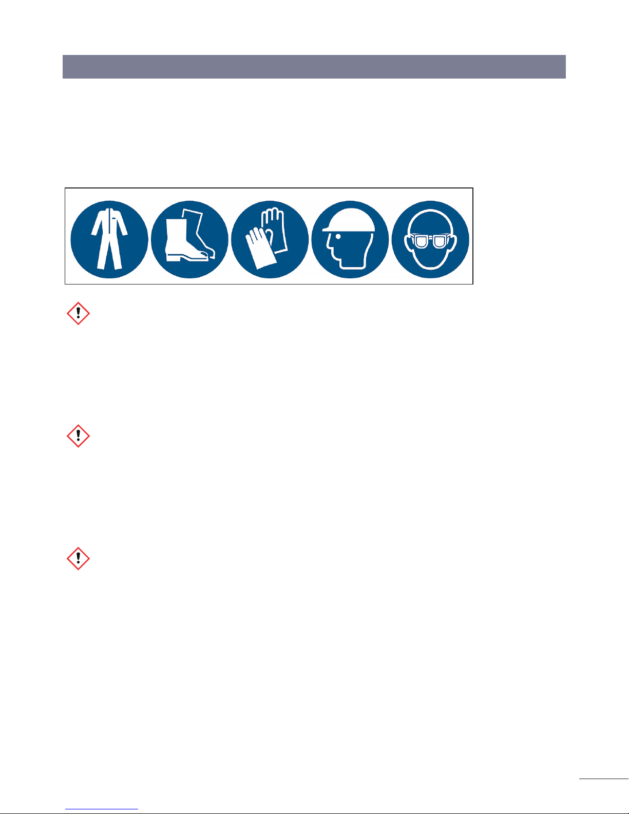
Required protective equipment:
WARNING
Risk of death due to suspended loads!
Falling loads can lead to severe injuries or even death.
• Never walk under suspended loads.
• Only move loads under supervision.
• Set down the load when leaving the workplace.
• Use personal protective equipment!
DANGER
Injury due to improper installation and initial commissioning!
Improper installation and initial commissioning can result in serious injury to persons and/or material damage.
• Before starting work, make sure there is sufficient space for assembly.
• Handle open, sharp-edged components carefully.
• Make sure the installation area is tidy and clean! Loosely stacked or scattered components and tools are a source of hazards.
• Install components properly. Comply with the specified screw tightening torques.
DANGER
Poisonous gases in case of fire!
In case of fire in the facility, the plastic parts (PVC) of the conductor-rail system emit poisonous gases (HCL).
• The system operator must take this into account accordingly when planning and take the appropriate protective measures.
• The building must be evacuated immediately.
• The fire brigade must be informed.
MV0815-0007-US | 01.08.19
7
CONDUCTOR BAR 0815 SERIES MANUAL
Page 8

SECTION 3 - ASSEMBLY
DANGER
Risk of injury by crushing skin and limbs!
There is a danger of crushing of skin and limbs due to:
• Spring force/gravity (stored energy).
• Current collector (spring force) during installation, dismantling and maintenance.
• Falling conductor-rail system components if they have not been properly installed or if operated in inappropriate operating conditions
(e.g. environment that contains solvents)
• Have installation done only by trained technicians.
• When working on the conductor-rail system, wear safety boots, safety gloves, and a safety helmet
• When changing the collector brush, follow the separate instructions for this task. See chapter 12.1 in BAL0815-0002-EN
• Only install the conductor-rail system where suitable operating conditions prevail. See chapter 3.3 in BAL0815-0002-EN
DANGER
Risk of injury due to grasping or impact!
Grasping and/or impact with moving conductor-rails (slip ring) or current collectors connected to the machine and other components must
be prevented.
• Cordon off the work area.
• Caution when working in the vicinity of the danger zone, in particular if protective devices (covers, enclosures, control devices) have
been removed or disabled.
• Caution when working in the vicinity of the danger zone, in particular below the conductor-rail.
• Falling conductor-rail system components if they have not been properly installed or if operated in inappropriate operating conditions
(e.g. environment that contains solvents).
• Use personal protective equipment!
DANGER
Risk of injury from cuts and cutting!
Cuts and amputations can occur:
• On sharp edges of the general components.
• On sharp edges of the conductor-rails.
• On cut edges when trimming the conductor-rails.
• On packaging materials (cartons, tapes, etc.)
• Use personal protective equipment!
8
CONDUCTOR BAR 0815 SERIES MANUAL
01.08.19 | MV0815-0007-US
Page 9

SECTION 3 - ASSEMBLY
CAUTION
Risk of puncture wounds and cuts!
The packaging material can contain sharp objects such as nails and wood splinters that can cause injury to limbs.
• Use personal protective equipment!
• Cordon off the work area!
• Caution when working in the vicinity, in particular below the conductor-rail.
DANGER
Risk of injury due to conductor-rails sliding out!
Risk of injury due to conductor-rails sliding out when the packaging units are held at an angle or carelessness with long loads.
• Use personal protective equipment!
• Cordon off the work area!
DANGER
Risk of death by electrocution!
Contact with components carrying electrical power can lead to death by electrocution or severe injury. Danger of injury due to shock
reactions, falling, or being thrown across the room due to electrical shock.
• The main power supply (from the building) must be disconnected in the installation area and secured against switching on again.
• Disconnect all electricity-supply power feeds.
• Check whether a voltage is still present in the components and take measures where necessary.
• Install the conductor-rail out of manual reach.
• Attach a sign saying “Risk of death by electrocution” with the relevant hazard symbol in all areas with live components.
• The customer must ground metallic components.
• The customer must provide protective devices.
• Make sure there is sufficient stability in the area.
WARNING
The system must be designed and operated in accordance with the prevailing ambient conditions!
WARNING
Secure conductor-rails against falling
• In application areas with personnel traffic and at an installation height of 3 m or more, conductor-rails must be secured against
falling!
MV0815-0007-US | 01.08.19
9
CONDUCTOR BAR 0815 SERIES MANUAL
Page 10
SECTION 3 - ASSEMBLY
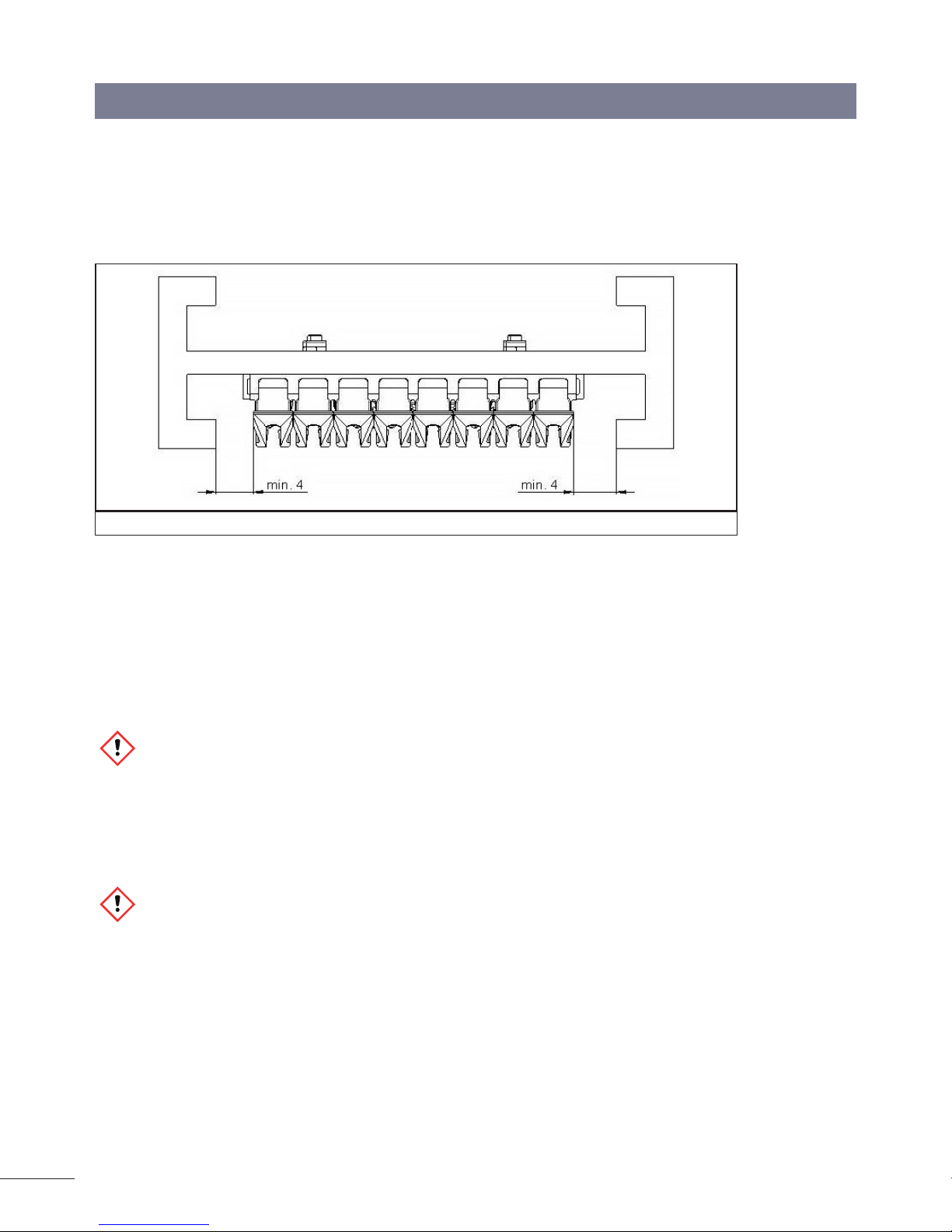
ATTENTION
To the side of the conductor-rail there must, a clearance of at least 4 mm from metal components must be maintained (see Figure 3-1) to
prevent mechanical collisions and guarantee sufficient electrical insulation distances!
Figure 3-1: Conductor side rail clearance
Providing additional protection against accidental contact at the conductor-rail end
An end cap is attached to the conductor-rail end as protection against accidental contact. When using dual current collectors, one of the
collector brushes, which will be live, might protrude from the end of the conductor-rail. Touching this collector brush might cause injury
from an electric shock, as a result of falling or being thrown across the room. The system operator must ensure that the current collector
does not project, instead remaining within the conductor-rails, or must make the danger area inaccessible (e.g. by providing protection
against accidental contact).
CAUTION
Take structural protective measures!
• Use control technology to ensure that the current collector never travels beyond the end of the conductor-rail.
• Also fit a contact guard that will safely cover the collector brush if it leaves the conductor rail!
CAUTION
Alert personnel to the hazard!
• Attach a sign saying “Risk of death by electrocution” with the relevant hazard symbol in all areas with live components.
10
CONDUCTOR BAR 0815 SERIES MANUAL
01.08.19 | MV0815-0007-US
Page 11

SECTION 3 - ASSEMBLY
Procedure
Required tools
Standard tool:
• Measuring tape
• Calipers
• Scribe
• Allen key (3 mm)
• Cutting tool (e.g. cordless angle grinder). For producing short lengths.
• File for deburring cut edges after trimming
• Cordless drill and countersink bit
• Screwdriver set
Special tool:
• Bending device (081091)
• Rail-dismantling tool
• Drilling jig for transition units
• Torque wrench (2 Nm) with 3 mm Allen key for rail connector
Personnel:
• Installation by technical personnel only
• At least two people
Customizing components
The customization of components is limited to the bending and trimming of the conductor-rail.
ATTENTION
The trimming of the conductor-rail must be done away from the installation area!
Trimming conductor-rail
The conductor-rails have a standard length of 4000 mm. Shorter lengths can be supplied but are generally produced at the building site.
Required tools:
• Cutting tool, preferably a battery angle grinder with 1 mm cutting disc
• Print cutter
Work steps:
• Cut the conductor material and insulation to the same length.
• Saw off the metal rail and PVC insulation away from the contact area using a cutting tool.
• Deburr the sawed end with a smooth file. Chamfer the contact surface in the whole rail base by 0.3–0.4 mm by 15° to guarantee a
problem-free passage of the collector brushes over the rail joint.
CAUTION
Sharp edges and burrs result in increased wear of the collector brushes!
A sharp edge and/or burr can rapidly wear away the carbon of the collector brushes.
MV0815-0007-US | 01.08.19
11
CONDUCTOR BAR 0815 SERIES MANUAL
Page 12
SECTION 3 - ASSEMBLY
• Clean the profile well and remove sawing debris
Figure 3-2: Deburr the conductor rail with smooth file
Figure 3-3: PEplus rail without end machining
12
CONDUCTOR BAR 0815 SERIES MANUAL
01.08.19 | MV0815-0007-US
Page 13

SECTION 3 - ASSEMBLY
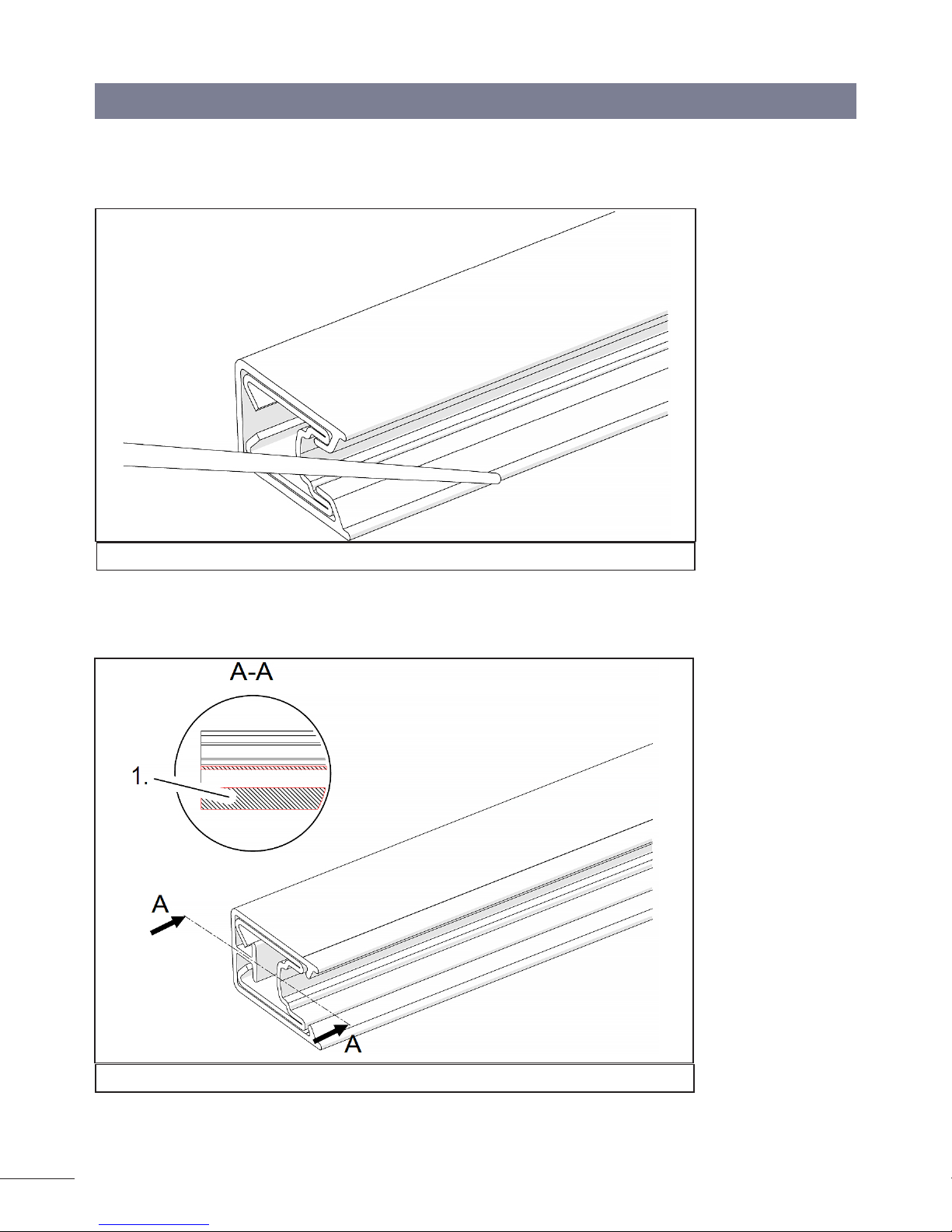
Figure 3-4: PEplus rail with end machining (plastic bar removed)
Figure 3-5: Rear side of rail
ATTENTION
The PEplus rail has a plastic bar in the insulating profile!
• Remove the plastic bar at each end using a print cutter or other suitable tool so that the connector or the end cap can be fitted
• The cutting tool 08-W100-0603 can be used for producing the end machining
Making a bend in the conductor-rail
Read and respect the additional operating instructions!
You can find additional information on the making a bend in a conductor-rail in BAL0800-0004.
Conductor-rail bends can be fabricated in the factory or on site. They are prepared using the bending device 081091.
For large installations, electrically driven bending devices available upon request.
MV0815-0007-US | 01.08.19
13
CONDUCTOR BAR 0815 SERIES MANUAL
Page 14

SECTION 3 - ASSEMBLY
Figure 3-6: Outside/inside bends and horizontal bend
To avoid undesired deformations of the conductor-rail, the plastic insert supplied must be inserted in the slit in the contact surface before
forming the bend and the removed once the bending process is complete.
Figure 3-7: Producing a horizontal bend w/ a plastic insert
Required tools:
• Bending device 08191
Work steps:
• Scribe the required bend on a flat surface (e.g., the floor).
• When making horizontal bends: Insert the plastic insert in the slot on the conductor-rail contact surface with the insulating profile
slid open.
• Using the setting spindle, move the upper bending roller upwards until the rail section can be inserted into the cutout provided in
the bending device.
• Adjust the position of the bending roller downwards and move the rail section back and forth.
• Bend the rail section by progressively advancing the central pressure roller.
• Repeat this process until the required radius is achieved.
• All subsequent rail sections that are to be formed to the same radius can now be bent using the existing setting.
• The rollers are designed for the various bends (horizontal/vertical, see BAL0800-0004 for the bending device for product ranges
0811 and 0815).
14
CONDUCTOR BAR 0815 SERIES MANUAL
01.08.19 | MV0815-0007-US
Page 15

SECTION 3 - ASSEMBLY
ATTENTION
Use modified PEplus rails for conductor-rail bends with radii < 1500 mm!
• Use modified PEplus rails (order no.: 081516-4x15) for preparing conductor-rail bends with radii < 1500 mm.
These rails are slotted on the rear side and can be bent without deformation of the insulation.
Figure 3-8: Slotted PEplus rail/Bending device
Assembling the conductor rail system
ATTENTION
To the side of the conductor-rail there must, a clearance of at least 4 mm from metal components must be maintained (see
Figure 3-9) to prevent mechanical collisions and guarantee sufficient electrical insulation distances!
Figure 3-9: Rail side clearance of at least 4 mm
Procedure during installation:
It makes sense to start the assembly at one end cap and to assemble the conductor-rail along the route.
MV0815-0007-US | 01.08.19
15
CONDUCTOR BAR 0815 SERIES MANUAL
Page 16

SECTION 3 - ASSEMBLY
Work steps:
• Indicate the positions/installation locations for power feed, customer’s fixed points, junction boxes, expansion elements, isolating
gaps and the guideway profile on the installation structure in accordance with the layout and allocation plan.
• Prepare the power feed and section transitions.
• Assembling the conductor-rail (see Setting the hanger clamps section on this page).
• Install conductor-rail sections including cut sections, lifters, conductor-rail bends and fixed points.
• Prepare the cut sections and conductor-rail bends in the switches.
• Check the mechanical installation.
Test steps to be performed during installation:
• Check the design against the layout and allocation plan.
• Maintain the hanger-clamp intervals; the rails must be properly engaged in the hanger clamp.
• All screw connections for the power feeds, connectors and end caps must be tightened to 2 Nm.
• All transitions and bends must be tested for functionality. Current collectors must not jam when passing through. Check for free
passage with a single current collector.
• The cabling must be checked (routing, labeling, etc.).
• Conduct a continuity and insulation check.
• Check the set dimension of the expansion element.
Setting the hanger clamps
The following must be observed when setting the hanger clamps:
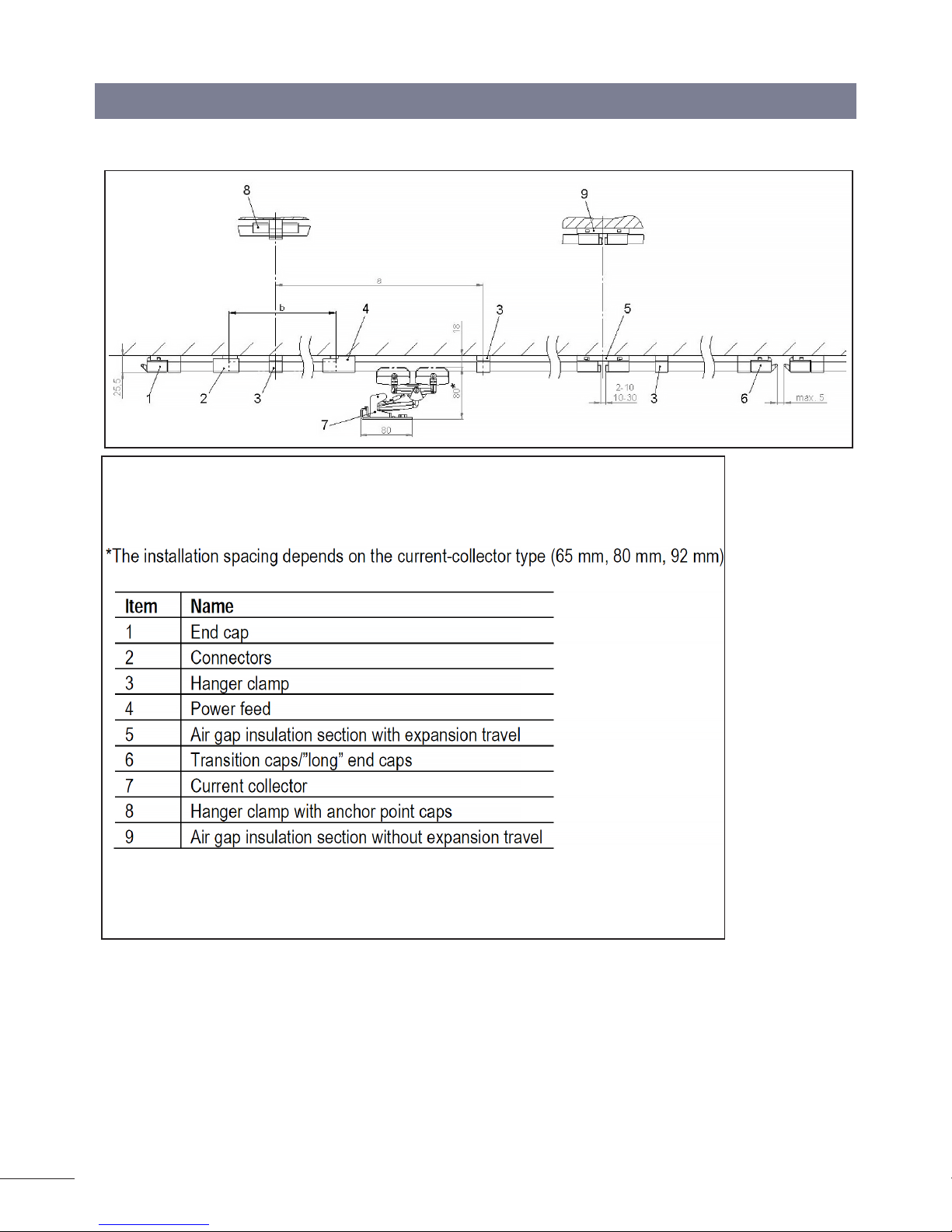
• Set the hanger clamps at intervals of approx. 500 mm and at intervals of 400 mm and 250 mm respectively for internal and external horizontal bends. Mount the hanger clamps at a distance of 100 mm – 150 mm from the end cap (see Fig. 13).
• At transitions and connection points, a minimum distance to end caps, connectors and expansion elements of at least 200 mm
must be maintained. Here, the hanger clamps must be set such that collisions of hanger clamps with other components of the system are avoided on expansion of the system.
• Hanger clamps are screwed or snapped into customer-specific guideway profiles. When installing, ensure that the pretensioning
is not too great. Excessive pretensioning will distort the hanger clamp. There is a risk that the hanger clamp will no longer rest flat
on the central bar of the EMS rails. Nevertheless, the hanger clamp must be so firmly seated in its position that it cannot dislocate
freely in the guideway profile.
• Frequently, the hanger clamps only become firmly seated in the EMS rail when the conductor-rails have been installed.
• Provide additional fixing for clip-in hanger clamps that do not remain in their positions.
16
CONDUCTOR BAR 0815 SERIES MANUAL
01.08.19 | MV0815-0007-US
Page 17

SECTION 3 - ASSEMBLY
Figure 3-10: Hanger clamp in EMS rail
Figure 3-11: Distance from hanger clamp to end cap
MV0815-0007-US | 01.08.19
17
CONDUCTOR BAR 0815 SERIES MANUAL
Page 18

SECTION 3 - ASSEMBLY
Figure 3-12: Comparison of correctly- and incorrectly-engaged rail
Figure 3-13: Clip hanger clamp into conductor rail
18
CONDUCTOR BAR 0815 SERIES MANUAL
01.08.19 | MV0815-0007-US
Page 19

SECTION 3 - ASSEMBLY
Installing conductor-rail and connectors
• After installation of the hanger clamps and preparations of the transitions and power feed points, push the conductor-rails into
the hanger clamps. Make sure that the conductor-rails engage correctly and the hanger clamp covers the insulation above and below
(see Figure 3-12)
• To simplify the installation of the subsequent conductor-rail, it makes sense not to engage the final meter of the current conductorrail.
This provides better accessibility of the conductor-rail joint (EMS). According to the guidelines of the automotive industry, the protective
conductor (PE) is provided as the 4th pole counted from above. This also corresponds to the standards of conductor-rail
Figure 3-14: Connector and two conductor rails
Screw connections are used to connect 2 conductor-rails. The connectors have a contact part and a rear clamping part.
• Push the connector into the conductor-rail such that the contact part sits in the interior of the conductor-rail and the clamping part
engages between the conductor-rail and the rear insulation (see Figure 3-16). A light pressure on both sides of the side surface of
the conductor-rail may make it easier to push the connector in.
• Push the connector into the two conductor-rails as far as the stops and then lightly tighten the connector from the front. Then
tighten the connector to 2 Nm with a torque wrench (see Figure 3-17).
• Put the insulating cap on from the back, engage it and check for secure hold.
• Push the conductor-rail into the hanger clamp next to the connection point until it engages.
MV0815-0007-US | 01.08.19
19
CONDUCTOR BAR 0815 SERIES MANUAL
Page 20

SECTION 3 - ASSEMBLY
Figure 3-15: Push the rails onto the connector
Figure 3-16: Correct/incorrect position of the clamp
Figure 3-17: Tighten connector/slide cap over rail connection
ATTENTION
Make sure that the connector cap is completely engaged on both sides of the insulating profile!
• Attach the connector cap centrally from behind clip it into the insulating profile.
• Engage the conductor-rails in the hanger clamps (see Figure 3-18).
20
CONDUCTOR BAR 0815 SERIES MANUAL
01.08.19 | MV0815-0007-US
Page 21

SECTION 3 - ASSEMBLY
Figure 3-18: Support profile with a conductor rail installed
CAUTION
• Conductor-rails can become deformed when bent!
• Check conductor-rail bends for the correct profile, because conductor-rails can deform when bent in the area of the insulation.
• Push a current collector through the conductor-rail by hand. The current collector must slide through the conductor-rail bend without
jamming.
• For a PEplus rail use a PEplus current collector with a broader brush.
• If the connector cap cannot rest on the guideway profile, hanger clamps must be placed at maximum distances of 200 mm on both
sides of the connector position (see Figure 3-19).
Figure 3-19: Rail connector
During installation, it can happen that a conductor-rail has to be taken out of a hanger clamp again. There is a dismantling tool for this
(order no.: 081092). This is used to dismantle the conductor-rail fixed in the hanger clamp and end caps bars (see Figure 3-20 and
3-21); see chapter 11.2 in BAL0815-0002-EN).
MV0815-0007-US | 01.08.19
21
CONDUCTOR BAR 0815 SERIES MANUAL
Page 22

SECTION 3 - ASSEMBLY
Figure 3-20: Dismantling tool
Figure 3-21: Dismantling tool in use
Installing a section power feed
The section power feed is installed instead of a connector. Here, a different clamping part and a power feed cap with room for a connecting cable to run out of it are used.
Figure 3-22: Correct/incorrect position of clamping unit
22
CONDUCTOR BAR 0815 SERIES MANUAL
01.08.19 | MV0815-0007-US
Page 23

SECTION 3 - ASSEMBLY
• Slightly loosen the screw connection with a screwdriver (½ turn), locking the square nut to facilitate loosening if necessary (see
Figure 3-23, left).
• Push the rail section into the free end of the section power feed as far as the stop (see Figure 3-23, right)
Figure 3-23: Installing a section power feed
• Slide the power feed cover over the pre-assembled rail connector (see Figure 3-24, left).
• Tighten the hexagonal screw to 2 Nm (see Figure 3-24, right)
Figure 3-24: Installing power feed cover
By using a section power feed, power can be supplied at any connection point in the route. The connection is made using a crimping
cable lug of 1.5 mm2 to 10 mm2 max. For phases, doubly insulated connecting cables must be provided for voltages > 48 V (max
conductor diameter 7 mm, see Figure 3-25).
• Trim the feed cable and strip the insulation to the desired length.
• Crimp the crimping cable lug of the section power feed onto the end of the cable. Do not remove the crimping cable lug from the
connector for this. Use a suitable crimping tool to connect the cable and cable lug.
• Loosen the screw with a SW-3 hexagonal screwdriver and insert the connector parts into the installed rail with insulation profile (see
Figure 3-23).
• Push the next rail section into the free end of the section power feed as far as the stop (see Figure 3-23).
• Tighten the hexagonal-socket-headed screw to 2 Nm (see Figure 3-24).
• Slide the contact-preventing power feed cap over the pre-assembled rail connector. Make sure that the square nut is aligned in the
recess of the connector cap. Engage the power feed cap on both sides of the insulating profile (see Figure 3-24).
MV0815-0007-US | 01.08.19
23
CONDUCTOR BAR 0815 SERIES MANUAL
Page 24

SECTION 3 - ASSEMBLY
ATTENTION
Make sure that the connector cap is completely engaged on both sides of the insulating profile!
• Provide a constructional strain relief for the feed cable.
If needed, any connector can be replaced by a power feed. If a power feed has to be introduced into the route after completion of the
installation, a 10 mm gap is cut into the rail. Then proceed as described above.
Figure 3-25: Power feed cover
If the power feed cover cannot rest on the guideway profile, hanger clamps must be placed at maximum distances of 200 mm on both
sides of the power feed position.
ATTENTION
Pre-assembled power feed cables with clamping units installed can be ordered as a unit!
24
CONDUCTOR BAR 0815 SERIES MANUAL
01.08.19 | MV0815-0007-US
Page 25

SECTION 3 - ASSEMBLY
Installing end caps and end power feeds
Drill the guideway profile in accordance with the layout and allocation plan. The use of a drilling jig is recommended in order to ensure
the exact position of the end caps. The drilling jig can be used both for straight transitions (e.g., entry into a lifter) and for angled cuts
(e.g., switches). For further information see MV0815-0006. Mount the hanger clamps at a distance of 100 mm – 150 mm from the end
cap (see Figure 3-11).
Figure 3-26: Drilling jig (08-V015-0474)/Screw on retaining plate
Tools:
• Self-tapping screws DIN 7500-1 M4, length profile bar width
• Drill diam. 3.6 mm
After installation of the end-cap bar (existing systems) or the retaining plate (new systems) for the transition caps, the end caps (with or
without power feed) are installed.
CAUTION
Ensure the correct positioning of the clamping unit!
Push the clamping unit of the end cap into the conductor-rail such the contact part sits in the interior of the conductor-rail and the
clamping part engages between the conductor-rail and the rear insulation (see Figure 3-27).
MV0815-0007-US | 01.08.19
25
CONDUCTOR BAR 0815 SERIES MANUAL
Page 26

SECTION 3 - ASSEMBLY
Figure 3-27: Correct/incorrect position of clamping unit
For end power feeds, the power can be supplied at the end of the route. An end power feed consists of an end cap with a power feed
clamping unit. The connection is made using a crimping cable lug with a conductor cross section of 1.5 mm2 to 6 mm2. For phases,
doubly-insulated connecting cables must be provided for voltages > 48 V.
Only for end power feeds:
• Trim the feed cable and strip the insulation to the desired length.
• Crimp the crimping cable lug of the end power feed onto the end of the cable. Do not remove the crimping cable lug from the con-
nector for this.
Figure 3-28: Mounting of the end cap
• Tighten the hexagonal-socket-headed screw to 2 Nm (see Figure 3-28).
• Provide a constructional strain relief for the end power feed cable.
• For power feed with pre-assembled cable part, push the clamping unit onto the end of the rail. Possibly loosen the clamping screw
somewhat and push the end cap onto the clamping part and the conductor-rail.
ATTENTION
It is recommended that the conductor-rail is not yet engaged in the adjacent hanger clamp!
26
CONDUCTOR BAR 0815 SERIES MANUAL
01.08.19 | MV0815-0007-US
Page 27

SECTION 3 - ASSEMBLY
Figure 3-29: Correct/incorrect position of clamping unit
Engage the end cap/end power feed into the retaining plate (see Figure 3-29).
Mounting the anchor point
A fixed point consists of a hanger clamp and 2 fixed point clamps per pole. The positions of the fixed points are determined when planning the system. The correct positioning of the fixed points is crucial for the thermal expansion behavior of the conductor-rail system.
Establishing a fixed point:
• Install a fixed point left and right of a hanger clamp per conductor-rail pole. The fixed-point cap is secured by an engagement cam
in a hole in the side wall of the conductor-rail.
• Scribe the position on the conductor-rail before installation.
• Put the fixed-point cap on the conductor-rail as a drilling jig and drill a 3-mm hole through the insulation and copper profile on one
side.
• Remove the fixed-point cap and replace it after rotating through 180° and insert an engagement cam into the hole.
MV0815-0007-US | 01.08.19
27
CONDUCTOR BAR 0815 SERIES MANUAL
Page 28

SECTION 3 - ASSEMBLY
Figure 3-30: Drill home for engagement cam, insulating profile and copper
element/ Rotate fixed-point cap through 180°
Figure 3-31: Insert engagement
cam into hole
Figure 3-32: Fully-assembled fixed point
CAUTION
Additional fixing of the hanger clamp is required for clip-in hanger clamps!
For clip-in hanger clamps, the hanger clamp that is to be used as the fixed point must be additionally secured to the support/building
structure with a screw.
28
CONDUCTOR BAR 0815 SERIES MANUAL
01.08.19 | MV0815-0007-US
Page 29

SECTION 3 - ASSEMBLY
Installing the current collector
Different current collectors are used for existing and new systems:
Figure 3-33: Single current collector
Figure 3-34: Dual current collector
MV0815-0007-US | 01.08.19
29
CONDUCTOR BAR 0815 SERIES MANUAL
Page 30

SECTION 3 - ASSEMBLY
Figure 3-35: EMS current collector
The single current collectors are mounted on base plates:
Figure 3-36: Mount the single current collector (081506…, 081507…,
081508…, 081509…) on base plate
30
CONDUCTOR BAR 0815 SERIES MANUAL
01.08.19 | MV0815-0007-US
Page 31

SECTION 3 - ASSEMBLY
Figure 3-37: Mount the EMS current collector (08150A / B…) on a base plate
ATTENTION
One screw can be put on each pole at the EMS current collector!
The screw heads are be covered by the current collectors!
• When installing current collectors, make sure the installation position is correct.
• For types without an integrated cable guide, take care with the selection of the connecting cable and ensure the connecting cables
are installed without tensile or directional forces:
• Only use highly flexible Conductix-Wampfler cables!
• For phases, doubly insulated connecting cables must be provided for voltages > 48 V.
• Do not bundle, fix or attach identification signs to the current-collector-connecting cable!
• Do not allow foreign objects to protrude into the moving range of the current collector and connecting cables!
• For systems with curves/bends, make sure that the current collector is installed in the pivot or steering axis—only by doing this can
it be ensured that the correct contact pressure is maintained when passing through (inside/outside) curves.
DANGER
Danger of electric shock!
Always protect unoccupied sockets on the current-collecting heads with protective caps!
The open connection must always be protected with a protective cap. This must also be observed when changing current-collecting
heads (see Figure 3-38).
MV0815-0007-US | 01.08.19
31
CONDUCTOR BAR 0815 SERIES MANUAL
Page 32

SECTION 3 - ASSEMBLY
DANGER
Risk of wear and damage!
The distance from the securing base surface of the current collector to the running surface of the conductor-rail is an important
functional dimension. This dimension changes in curves if the current collector is not installed directly under the wheel contact point of
the EMS hanger. If the distance from the wheel contact point is too great, the permissible tolerances may be exceeded in tighter curves.
Result: Damage, high wear
• Compliance with the installation tolerances must therefore be checked in the tightest curved section!
Figure 3-38: Protect unoccupied current-collector-connecting cable with the
protective cap provided (08150A / B…; 08150x…)
ATTENTION
The protective cap is supplied pre-installed on the current collector. A replacement protective cap can be ordered as a
packing unit with material number 08-A025-0080! Install all current-collector cables highly flexibly and without tensile or
directional forces!
Figure 3-39: Comparison of the correct and incorrect position of the socket
32
sleeve
CONDUCTOR BAR 0815 SERIES MANUAL
01.08.19 | MV0815-0007-US
Page 33

SECTION 3 - ASSEMBLY
WARNING
Bending up of the socket sleeve!
If the socket sleeve is placed incorrectly on the collector brush, the socket sleeve bends up, the socket sleeve is damaged and the
contact with the brush is minimized.
• Ensure the socket is correctly positioned to prevent the socket sleeve from bending up!
CAUTION
Contact problems or increased heating!
• Clean the collector brush before commissioning and remove dirt, oxidation, pitting corrosion and other impurities by means of a
brass brush or abrasive paper (320 grit).
DANGER
Risk of damage when cleaning the conductor-rail!
When cleaning, only loose or lightly adhering dust or foreign substances may be removed.
• Do not use contact spray (formation of silicon carbide/abrasive and/or damage of plastic parts)
• Only use abrasives or brushes as tools for removing heavy build-ups at minor burns under supervision.
• Persistent use with removal of the lubricant layer or running surface damages the rail (see also WV0800-0001 and WV0800-0004)
Typical installation errors that have a negative affect on the running behavior of the current collectors:
• Conductor-rails are not correctly engaged in the hanger clamp
• Rail bends are tapered due to progressive bending
• Switches and lifters are incorrectly set (end positions, dimensional tolerances) or yielding
• Incorrect current-collector-connecting cable
• Current-collector-connecting cable not used as (not free of directional and tensile forces)
• Installation positions are not within specification Permissible tolerances exceeded in bends and curves
• Rail joints and transitions have not been de-burred
Additional documents
Read and respect the additional operating instructions!
You can find further information on the installation of conductor-rail systems in the following instructions:
• MV0815-0005 Expansion module and expansion element
• MV0815-0006 Transitions
• MV0815-0007 Installation instructions for conductor-rail system 0815
• BAL0815-0001 Carbon-brush sensor unit
• BAL0800-0004 Bending device for product ranges 0811 and 0815
MV0815-0007-US | 01.08.19
33
CONDUCTOR BAR 0815 SERIES MANUAL
Page 34

34
CONDUCTOR BAR 0815 SERIES MANUAL
01.08.19 | MV0815-0007-US
Page 35

35
MV0815-0007-US | 01.08.19
CONDUCTOR BAR 0815 SERIES MANUAL
Page 36

36
CONDUCTOR BAR 0815 SERIES MANUAL
01.08.19 | MV0815-0007-US
Page 37

37
MV0815-0007-US | 01.08.19
CONDUCTOR BAR 0815 SERIES MANUAL
Page 38

CONDUCTIX-WAMPFLER FIELD SERVICE
Need Field Service for our products? We Can Handle It!
Ask us for a quote on expert system installations, inspections, preventative maintenance, and repairs/retrofits.
As the world’s largest single source manufacturer of mobile electrification products, Conductix-Wamplfer has the unique ability to offer a
degree of service not found anywhere else. Conductix-Wampfler’s team of highly qualified service technicians and engineers have years of
experience servicing our complete line of products.
We can provide:
• Annual Service contracts
• Installation
• Commissioning
• Installation supervision to ensure your installers avoid common mistakes.
• Troubleshooting to get you up and running.
• Pre-planned inspections to complement your preventive maintenance program.
Call 1-800-521-4888 for further details.
38
CONDUCTOR BAR 0815 SERIES MANUAL
01.08.19 | MV0815-0007-US
Page 39

NOTES
MV0815-0007-US | 01.08.19
39
CONDUCTOR BAR 0815 SERIES MANUAL
Page 40

www.conductix.us
USA / LATIN AMERICA
10102 F Street
Omaha, NE 68127
Customer Support
Phone +1-800-521-4888
Phone +1-402-339-9300
Fax +1-402-339-9627
info.us@conductix.com
latinamerica@conductix.com
© Conductix-Wampfler | 2017 | Subject to Technical Modifications Without Prior Notice
Contact us for our Global Sales Offices
CANADA
1435 Norjohn Court
Unit 5
Burlington, ON L7L 0E6
Customer Support
Phone +1-800-667-2487
Phone +1-450-565-9900
Fax +1-450-951-8591
info.ca@conductix.com
MÉXICO
Calle Treviño 983-C
Zona Centro
Apodaca, NL México 66600
Customer Support
Phone (+52 81) 1090 9519
(+52 81) 1090 9025
(+52 81) 1090 9013
Fax (+52 81) 1090 9014
info.mx@conductix.com
BRAZIL
Rua Luiz Pionti, 110
Vila Progresso
Itu, São Paulo, Brasil
CEP: 13313-534
Customer Support
Phone (+55 11) 4813 7330
Fax (+55 11) 4813 7357
info.br@conductix.com
CONDUCTOR BAR 0815 SERIES MANUAL 01.08.19 | MV0815-0007-US
 Loading...