

Page 1
E-360N050-0817
Installation, Operating, and
Maintenance Instructions Manual
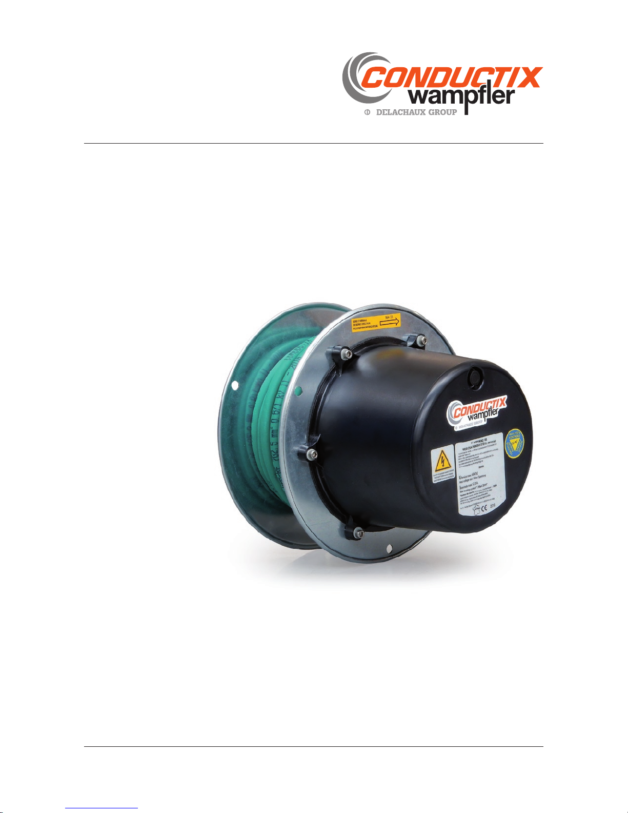
Spring Cable Reels
SR10 | SR20 | SR30
Page 2

SR10 | SR20 | SR30
Installation, Operating and Maintenance Instructions Manual
P. 2/40
E-360N050-0817
Contents
A General information 3
A.1 Information on the IOM Instructions Manual .............................3
A.2 Limit of liability ........................................................................3
A.3 Copyright ................................................................................3
A.4 Spare parts .............................................................................3
A.5 Warranty .................................................................................3
A.6 Customer service ....................................................................3
B Safety instructions 4
B.1 Definition of symbols ...............................................................4
B.2 Personnel requirements ...........................................................4
B.2.1 Qualifications ..........................................................................................4
B.2.2 Unauthorized personnel ...........................................................................4
B.2.3 Instruction ...............................................................................................4
B.3 Personal protective equipment .................................................5
B.3.1 Mandatory protection during any intervention ..........................................5
B.3.2 Additional protection ...............................................................................5
B.4 Intended use ...........................................................................5
B.5 Protective measures ................................................................6
B.6 Specific hazards ......................................................................6
B.7 Actions in the event of accidents and faults ..............................7
B.7.1 Measures in the event of accidents: .........................................................7
B.7.2 Measures to be taken in case of malfunction: ..........................................7
C Specifications 8
C.1 General information .................................................................8
C.2 Operating conditions ...............................................................8
C.2.1 General conditions ..................................................................................8
C.2.2 Specific conditions ..................................................................................8
C.3 Identification ...........................................................................8
C.3.1 Spring cable reel .....................................................................................8
C.3.2 Slip ring assembly ...................................................................................8
D Product description and mode of operation 9
D.1 Assembly and designation ......................................................9
D.2 Cable ......................................................................................9
D.3 Mounting flange ....................................................................10
D.4 Cable drum ...........................................................................10
D.5 Spring motor .........................................................................10
D.6 Slip rings ...............................................................................11
D.6.1 General information ...............................................................................11
D.6.2 Pole marking .........................................................................................11
D.6.3 Slip ring type USR050 ...........................................................................12
D.6.4 Slip ring type USR090 ...........................................................................13
D.7 Slip ring housing ....................................................................14
D.8 Options .................................................................................14
D.8.1 Steel slip ring housing ‘CM’ ...................................................................14
D.8.2 Brackets ‘SE’, ‘BR’ and ‘S P’ ..................................................................14
D.8.3 Adapter flange ‘AB’ ...............................................................................14
E Handling, packaging and storage 15
E.1 Handling ...............................................................................15
E.1.1 Safety Instructions ................................................................................15
E.1.2 Transport inspection ..............................................................................15
E.2 Packaging .............................................................................15
E.3 Storage of packed parts ........................................................16
F Installation 16
F.1 Safety ...................................................................................16
F.2 Delivery condition ..................................................................18
F.3 Installation of the reel ............................................................18
F.3.1 Handling ................................................................................................18
F.3.2 Orientation of the reel ............................................................................19
F.3.3 Cable laying path .................................................................................. 20
F.3.4 Rotation axis ........................................................................................ 20
F.3.5 Fastenings ........................................................................................... 20
F.3.6 Use with deflecting pulley ..................................................................... 21
F.4 Installation of the wound cable .............................................. 21
F.4.1 Cable length ......................................................................................... 21
F.4.2 Installation on the cable drum ............................................................... 21
F.5 Installation of the fixed cable ................................................. 22
F.6 Slip ring connections ............................................................ 23
F.6.1 Connections to the brush holders (wound cable) ................................... 23
F.6.2 Connections to the rings (fixed cable) ....................................................24
F.7 Pre-tensioning of the spring motor ........................................ 25
F.8 Securing of the cable to the anchor point .............................. 25
G Commissioning 26
G.1 Safety .................................................................................. 26
G.2 General information .............................................................. 27
G.3 Check-list before commissioning .......................................... 27
G.4 Operation tests ..................................................................... 27
H Operation 28
H.1 Safety .................................................................................. 28
H.2 Operation ............................................................................. 29
I Troubleshooting 30
I.1 Safe ty .................................................................................. 30
I.2 Spring reel and cable .............................................................31
I.3 Slip rings ...............................................................................31
J Maintenance 32
J.1 Safety .................................................................................. 32
J.2 Maintenance schedule .......................................................... 33
J.3 Servicing .............................................................................. 33
J.3.1 Cleaning ............................................................................................... 33
J.3.2 Cable ................................................................................................... 33
J.3.3 Slip rings .............................................................................................. 34
J.4 Spare parts .......................................................................... 35
J.4.1 Model SR10 ......................................................................................... 35
J.4.2 Model SR20 ......................................................................................... 36
J.4.3 Model SR30 ......................................................................................... 37
K.1.1 Cable glands ........................................................................................ 38
K Dismantling and disposal 38
K.1 S afe ty .................................................................................. 38
K.2 Dismantling .......................................................................... 39
K.3 Disposal ............................................................................... 39
L Declaration of incorporation 40
Page 3
P. 3/40
E-360N050-0817
SR10 | SR20 | SR30
Installation, Operating and Maintenance Instructions Manual
General informationA
Safety risk due to poor spare parts!
Incorrect or faulty spare parts can cause damage, malfunctions or total failure of the equipment, as well as affecting safety.
Therefore:
Use only original manufacturer’s spare parts! Fastenings must be replaced by fastenings of quality classes and dimensions equivalent to the original. -
WARNING
Information on the IOM Instructions ManualA.1
This manual is intended to facilitate safe installation and use of the equipment. It is an integral part of the equipment and must be kept in close
proximity to so as to allow its consultation by the staff at any time. Before starting the work, staff must read these instructions carefully and
understand them. It is a basic requirement for safe working to respect all safety instructions and procedures in this manual.
Local regulations for accident prevention and general safety rules applicable for the area of use of the device must also be met. Illustrations
are provided for information only and may differ from the actual installation of the spring driven reel.
Limit of liabilityA.2
All the information and instructions contained in this manual has been compiled taking into account the standards and regulations in force, the
best engineering practices, and the results of the experience that Conductix-wampfl er has accumulated over many years.
The manufacturer is in no case responsible for damages resulting from:
Non-compliance with the instructions contained in this manual, Incorrect use, Use by unqualifi ed personnel, Unauthorized modifi cations to the reel, Technical modifi cations to the installation, Use of unauthorized spare parts and/or accessories. -
The equipment actually delivered may differ from the one presented in the explanations and illustrations described here if special variants or
additional options are used, or due to recent technical changes.
The obligations contained in the delivery contract and in our general conditions of sale apply, as well as the conditions of delivery of the manufacturer and all regulations applicable at the time when the contract was concluded.
All products can be subject to technical modifi cations within the framework of improvement in the function and the technological development
of components.
Conductix-wampfl er has tested and validated cables that are suitable for its reels and guarantee optimum lifetime of the reel and cable combination. Conductix-wampfl er disclaims any responsibility for the lifetime of the cable if it is not of its supply and if the information allowing
its sizing is incorrect: minimum and maximum diameters, minimum bend radius, maximum pull in service, maximum current, voltage drop,
maximum and minimum working temperatures, and maximum speed of use on the reel.
CopyrightA.3
These Instructions for installation and use are subject to copyright and intended exclusively for internal use.
The provision of installation and operating instructions to third parties, copying, in any form, even in part, as well as the reuse and/or the
disclosure of their contents are not permitted without the written approval of the manufacturer, except for internal use. Any violation will be
subject to damages; additional claims not being excluded.
Spare partsA.4
Spare parts must be supplied exclusively by authorized re-sellers or directly from the manufacturer. The address appears on the fi rst page of
this manual.
WarrantyA.5
The warranty conditions are shown in the manufacturer’s “General conditions of sale”.
This equipment is not designed to be used in EXplosive ATmospheres (ATEX)
in accordance with the defi nition in directive 2014/34/UE dated 29 march 2014
Customer serviceA.6
Our customer service team is available for technical information. The address appears on the fi rst page of this manual.
Our staff is also always interested in new information and experiences in the fi eld that could be useful for the improvement of our products.
Page 4
SR10 | SR20 | SR30
Installation, Operating and Maintenance Instructions Manual
P. 4/40
E-360N050-0817
Safety instructionsB
Defi nition of symbolsB.1
The safety instructions are identifi ed in this manual by symbols.
Warnings are used to indicate the degree of danger. Always observe danger and safety information and work with care to avoid accidents,
bodily harm or damage to the equipment!
Indicates an immediately hazardous situation, which if not avoided, may result in death or serious injury.
DANGER
Indicates a possibly hazardous situation, which if not avoided, may result in death or serious injury.
WARNING
Indicates a possibly hazardous situation, which if not avoided, may result in moderate or minor injury and property damage.
CAUTION
Tips and recommendations:
Refers to useful tips and recommendations as well as information for effi cient and trouble-free operation.
Personnel requirementsB.2
Qualifi cationsB.2.1
Injury due to insuffi cient qualifi cation!
Improper use can result in serious injury and property damage.
Therefore:
All activities may only be performed by qualifi ed personnel! -
WARNING
The following qualifi cations have been mentioned in these IOM instructions for different areas of operation:
Trained personnel/operators have been instructed by the operating body about the tasks assigned to him/her and the possible hazards resulting from improper use.
Qualifi ed specialists due to their specialized training, knowledge, and experience, as well as knowledge of applicable regulations, are capable of carrying out work assigned to them, while independently recognizing and avoiding possible risk.
Only those persons are authorized as personnel who can be expected to perform their work reliably. People whose capacity for reaction is infl uenced e.g. by drugs, alcohol, or medications are not authorized.
When selecting personnel, follow all age-and occupation-specifi c guidelines applicable at the location of use. -
Unauthorized personnelB.2.2
Danger due to unauthorized personnel!
Unauthorized personnel who do not meet the requirements described here do not understand the danger in the working area.
Therefore:
Keep unauthorized personnel away from the working area. In case of doubt, address the persons and direct them away from the working area. Stop work as long as unauthorized personnel is in the working area. -
WARNING
InstructionB.2.3
Before commissioning the equipment, personnel must be instructed by the operating body.
For better tracking, log the implementation of the instruction as follows:
Date Name Type of instruction Given by Signature
01/01/2016 Pierpol Jacques First aid training for personnel Jacques Pierre-Paul
Page 5
P. 5/40
E-360N050-0817
SR10 | SR20 | SR30
Installation, Operating and Maintenance Instructions Manual
Personal protective equipmentB.3
Mandatory protection during any interventionB.3.1
Work safety clothing
is close-fi tting work clothing that has a low tearing strength with tight arms and no parts that protrude. It is mostly used as
protection from getting caught by moving machine parts. Do not wear any rings, chains or any other jewelry!
Safety shoes
used to protect from falling heavy parts and slipping on slippery fl oors.
Additional protectionB.3.2
When carrying out particular tasks, special safety equipment is required. The individual sections of these instructions specify this equipment
in detail. The following particular safety gear is explained below:
Protective gloves
for the protection of hands from friction, scrapes, stabbing, or deep wounds, as well as from contact with hot surfaces.
Hard hat / Helmet
for protection from falling and fl ying parts and materials.
Intended useB.4
The equipment is exclusively designed and built for the intended use described here.
The spring cable reel is used for the winding and unwinding of a mobile power supply line (cable suitable for the use on reels) for a mobile
machine.
Claims of any kind due to damages from improper use are excluded.
The operator bears sole liability for all damages resulting from unintended use.
Possible injury resulting from improper use!
Any application that deviates from or goes beyond the intended use of the machine can result in a hazardous situation.
Therefore:
The spring cable reel may only be used as intended. Comply strictly with all specifi cations of these installation and operating instructions. -
The following uses of the device are forbidden:
Using the device with unapproved accessories not authorized by the manufacturer. Operation of the device by untrained personnel. Operation of the device when installed on an improper foundation / base. Operation under conditions other than the agreed environmental and operating conditions. -
WARNING
Safety glasses
for the protection of the eyes.
Mask
For protection against materials, particles and organisms.
Especially: wear dust from slip rings or brushes.
Page 6
SR10 | SR20 | SR30
Installation, Operating and Maintenance Instructions Manual
P. 6/40
E-360N050-0817
Specifi c hazardsB.6
The following section lists residual risks determined based on a risk assessment.
Follow the safety instructions listed here and the warnings in other sections of these installation and operating instructions in order to reduce
health hazards and avoid dangerous situations.
Danger of death from electrocution!
The equipment is fed by an electric current. Upon contact with live components or in case of damaged insulation, there is a
danger of fatal injury.
Therefore:
Operate the system only with complete safety systems in working order! Replace loose or damaged cables and lines immediately! Avoid contact with live parts! Use insulated tools! When disconnecting the safety measures, e.g. during commissioning, troubleshooting, and maintenance, shut the system down and secure it against unauthorized, unintentional, or accidental activation!
Check that no voltage is applied to the system before any work on it! -
DANGER
Danger of death due to suspended loads!
During loading / unloading operations, there is a danger of death from falling parts or those swinging out of control.
Therefore:
Never step under suspended loads. Follow the specifi cations for the lifting points provided. Use only authorized lifting appliances and separate lifting accessories with suffi cient load capacity. Do not use torn or worn ropes, textile slings or straps. Do not attach ropes or straps to sharp corners and edges, and do not knot or twist them. Only move loads under supervision. Set down the load when leaving the workplace. -
WARNING
Danger of death by electrocution!
The slip ring housing and its mounting on the reel are not designed to withstand external mechanical loads other than those
identifi ed for the normal operation of the installation.
Therefore:
Do not climb or walk on the slip ring housing. -
DANGER
Protective measuresB.5
The device is used in the commercial/industrial sector. The operating body of the device is thus subject to legal obligations for workplace
safety. In addition to the safety guidelines in these installation and operating instructions, the safety, accident protection, and environmental
protection regulations applicable to the place of operation of the unit must be followed.
This particularly includes:
The operator must be informed of applicable workplace safety guidelines and identify any additional hazards that result from the special working conditions at the location of use of the device. These must be expressed in the form of operating instructions for operation of the
device.
The operator must verify during the entire time the device is in use that the operating instructions provided still correspond to the current state of regulations, and adapt the instructions as necessary.
The operator must clearly regulate and determine responsibilities for installation, operation, troubleshooting, and maintenance. The operator must ensure that all employees involved with the unit have read and understood these installation and operating instructions. He must furthermore train personnel at regular intervals and inform them of hazards.
The operator must provide personnel with all required safety gear. -
The operator is furthermore responsible for ensuring that the device is always in a technically trouble-free condition. The following thus
applies:
The operator must ensure that the maintenance schedule described in these installation and operating instructions is followed. The operator must have all safety systems regularly inspected for functionality and completeness. -
Page 7
P. 7/40
E-360N050-0817
SR10 | SR20 | SR30
Installation, Operating and Maintenance Instructions Manual
Danger of injuries by friction and scrapes!
During operation of the system, the rotation of the reel and its projecting threaded rods and other parts may cause friction or
scrapes.
Therefore:
Do not stay near the reel. Take protective measures (e.g. safety fence) to keep a minimum distance from the rotating reel to rule out danger. -
CAUTION
Actions in the event of accidents and faultsB.7
Measures in the event of accidents:B.7.1
Secure the location of the accident. Shut down the system and secure it against unauthorized, unintentional, and/or accidental activation. Evacuate personnel from of the danger area. Notify rescue services. Take fi rst-aid measures. Inform responsible parties at the place of operation. Inform rescue services in detail. -
Measures to be taken in case of malfunction:B.7.2
Shut down the system and secure it against unauthorized, unintentional, and/or accidental activation. Secure the work area against entry. Involve qualifi ed personnel for fault analysis. -
Risk of falls!
The spring cable reel is mostly composed of rotating moving parts. The reel and its bracket are not designed to withstand
mechanical loads other than those identifi ed during normal operation of the installation.
Therefore:
Do not climb or walk on the reel. -
WARNING
Danger of pinching, crushing and shearing injuries!
Locations:
Between cable and cable Between cable and drum fl anges Between cable and drum body Between rotating parts and optional bracket ‘SE’ (if supplied) Between cable and optional roller guide arm ‘BR’ (if supplied) At the pivot of the optional swivel bracket ‘SP’ (if supplied) -
Therefore:
Never work on moving parts. During commissioning, operation and maintenance, take protective measures (e.g. safety fence) or keep a minimum distance from rotating parts to rule out danger.
When disconnecting the safety means, e.g. during commissioning, troubleshooting, and maintenance, shut the system down and secure it against unauthorized, unintentional, or accidental activation.
CAUTION
Page 8
SR10 | SR20 | SR30
Installation, Operating and Maintenance Instructions Manual
P. 8/40
E-360N050-0817
Operating conditionsC.2
General conditionsC.2.1
Criteria Value Unit
Ambient temperature -20 up to +60 °C
Max. relative humidity ≤ 95 %
Max. operating travel speed
60 (retrieve application)
30 (lift application)
m/min
Max. acceleration 0.3 m/s²
Specifi c conditionsC.2.2
Low temperature option: from -40 up to +40°C
Specifi c conditions defi ned and validated with the customer may apply in place of the general conditions.
Risk of injury due to incorrect use!
The reel is designed to be used only in a neutral industrial environment, and according to the criteria listed below.
Therefore:
Conductix-wampfl er declines any responsibility in the event of:
Non-compliance with the terms and conditions of use Damage to all or part of the reel caused by shock, excessive vibration or any other unanticipated use. -
WARNING
Specifi cationsC
General informationC.1
The spring cable reel is used for the automatic winding and unwinding of a mobile power supply line (cable suitable for the use on reels) for a
mobile machine. The exact specifi cations of the spring driven reel can be found in the order confi rmation. The dimensions of the spring driven
reel can be found in the dimension sheet.
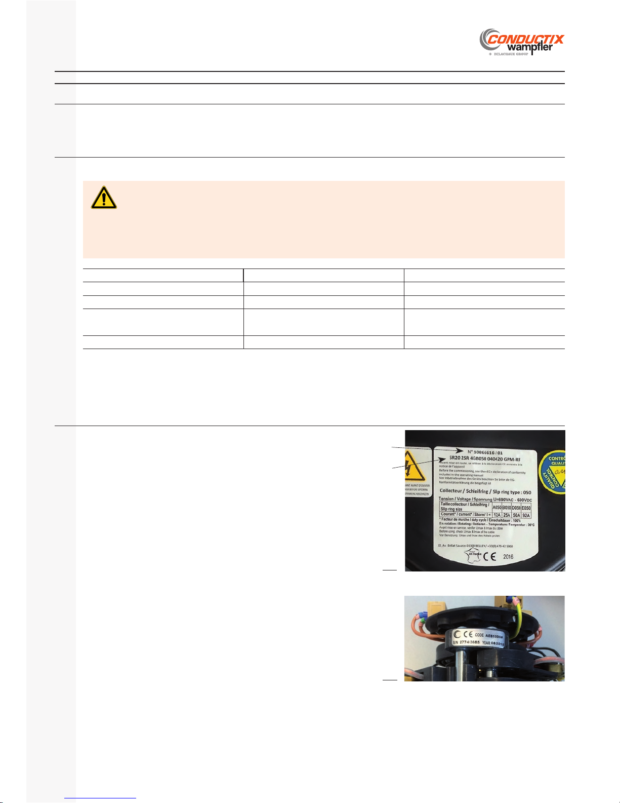
Identifi cationC.3
The type label of the reel is located at the rear of the slip ring housing.
When communicating about the specifi c cable reel provided (e.g. spare parts, modi-
fi cations, etc.), please specify the type and order number.
Order No. / Serial No.
Reel designation
Spring cable reelC.3.1
The identifi cation label is located on the slip ring assembly, on the side nearest the
connection terminals.
Use this information in any communication concerning the slip ring assembly.
Slip ring assemblyC.3.2
Fi g.1
Fig.2
Page 9
P. 9/40
E-360N050-0817
SR10 | SR20 | SR30
Installation, Operating and Maintenance Instructions Manual
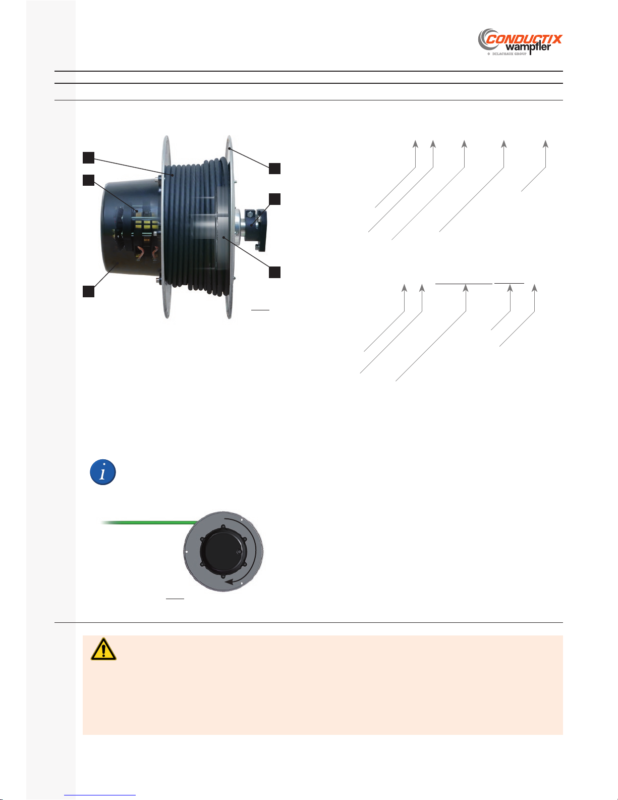
(Wound) cable1.
Mounting fl ange2.
Cable drum3.
Spring motor4.
Slip ring assembly5.
Slip ring housing6.
Risk of malfunction!
Conductix-wampfl er has tested and validated cables that are suitable for its reels and guarantee optimum lifetime of the reel
and cable combination.
Therefore:
Conductix-wampfl er disclaims any responsibility on the service life of the cable if it is not of its supply and if the information
allowing the sizing is incorrect:
Min./max. cable OD, min. bending radius, max. operating voltage, max. carrying current capacity, voltage drop, min./max. operating temperatures, max. reeling speed.
WARNING
Unless otherwise specifi ed when ordering,
spring reels SR are built according to a
winding direction 1 (clockwise direction
viewed from slip ring housing).
Product description and mode of operationD
Assembly and designation D.1
CableD.2
Reel designation
Winding direction
Cable drum type
SR20 2SR 4GD050 040420 GPM-RF
Spring motor arrangement
Slip ring type and no. of poles
No. of cores, cross section
and length of cable
Cable type
Reels SR-Express:
Cable drum type
SR30 2PA 4GD090+7B CM SE E0
Spring motor arrangement
Slip ring type and no. of poles
Options
1)
Environment
2)
Other reels SR:
1)
Options
‘CM’: steel slip ring housing, see § D.8.1. ‘SE’, ‘BR’ or ‘SP’: brackets, see § D.8.2. ‘AB’: adapter fl ange, see § D.8.3. -
2)
Environment
EO: standard conditions E1: low temperature E3: severe conditions -
Overview of components
2
4
1
3
5
6
Fig.3a
Winding
direction 1
Fig.3b
Page 10
SR10 | SR20 | SR30
Installation, Operating and Maintenance Instructions Manual
P. 10/40
E-360N050-0817
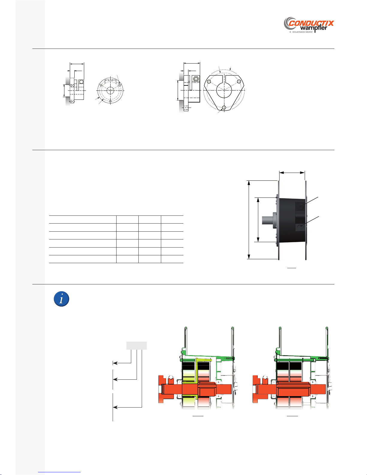
Ø45 min.
Ø60
3×Ø7 /120°
39
12
Ø70
SR10
Ø55 min.
12
3×Ø9 /120°
Ø9042Ø108
SR20 - SR30
Cable drum SR10 SR20 SR30
ØA [mm] 170 220 270
ØB [mm] 320 400 450
C [mm] 114 129 179
Min./max. cable OD [mm] 8 / 16 8 / 21 8 / 27
Max. winding diameter [mm] 270 340 400
The cable drum consists primarily of:
A drum body made from reinforced plastic (containing the spring motor)
Two profi led steel fl anges A hollow shaft A pair of sealed, lubricated for life ball bearings. -
The drum body is equipped with two cable entries: S1 for clockwise
winding direction, S2 for counter-clockwise winding direction.
The spring motor is fi tted inside the cable drum. Depending on the model, it is composed of 1 to 3 springs linked together in series or in
parallel.
For safety reasons, the springs are neither accessible nor removable individually (glued bolts).
If a spring breaks, the entire cable drum must be replaced (See § J.4.)
Mounting fl angeD.3
Cable drumD.4
Spring motorD.5
Spring motor designation
2 P A
No. of springs: 1 up to 3
Spring arrangement:
Series
Parallel
Spring type:
stAndard
Long
Reinforced
ØB
ØA
C
S1
S2
Fig.4
A motor with two identical springs •
in series allows twice the number of
working turns.
Fig.5a
A motor with two identical springs in •
parallel generates twice the tensile
pull.
Fig.5b
Page 11
P. 11/40
E-360N050-0817
SR10 | SR20 | SR30
Installation, Operating and Maintenance Instructions Manual
Performance data pertain to rotating operation, not stationary operation.
Deviations may be possible on a project-specifi c basis, for example connection plates or strand connections with or without
terminal boxes.
The slip rings can be used with a TN power supply system referenced to the Earth. An isolation transformer (delta wired
at the secondary, with neutral to earth) is always necessary for circuits, whether asymmetrically earthed or not.
WARNING
The Earth pole ‘PE’ is always positioned fi rst on the drum side The power poles (phases) are ordered from ‘Pn’ to ‘P1’ from the pole ‘PE’
The control poles (phases) are ordered from ‘n’ to ‘1’ from the pole ‘P1’
Max. operating voltage 690 V-AC / 600 V-DC
Max. rotation speed
USR050 : 140 min
-1
USR090 : 80 min
-1
Frequency 50 / 60 Hz sinusoidal
Min./max. ambient temperature -20°C / +60°C (derating above +30°C)
Max. relative humidity 90 % (w/o condensation)
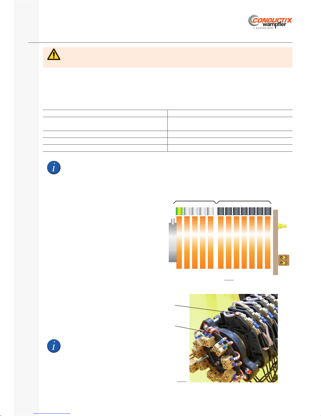
The slip ring is used to ensure the electrical connection (power, controls and signals) between the rotating part of the reel (cable drum) and
the fi xed part (mounting fl ange and shaft):
The rings are connected to the fi xed cable through the fi xed part of the reel (shaft). The brush holders are driven in rotation by the rotating part of the reel (cable drum) and are connected to the wound cable. -
Slip ringsD.6
General informationD.6.1
Pole markingD.6.2
To identify the connection between the brush
holder and the ring, refer to the markings on the
conductors.
Pn P... P2 P1 n n-1 ... ... ... ... 1PE
Fig.6a
Brush holder marking
Ring marking
Fig.6b
DRUM SIDE
POWER CONTROL
CONNECTION PL ATE
Page 12
SR10 | SR20 | SR30
Installation, Operating and Maintenance Instructions Manual
P. 12/40
E-360N050-0817
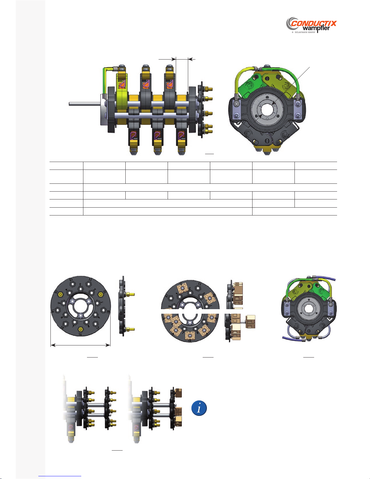
Ring type A050 B050 D050 E050 U050 W050
Amperage [A]
1)
12 25 50 92
analogic signals
4-20 mA
digital signals
max. 12 Mbps
Diameter [mm] 50
Pxx [mm] 9 10 15 21 9 9
Ring material brass silver-plated brass gold-plated brass
Brush material copper graphite silver graphite
1)
Slip rings in motion (rotation), @ +30°C and duty 100%. Above 30°C, amperage value must be de-rated.
Connection plates
Connections of the fi xed cable cores (through the shaft) to the rings.
Several confi gurations are possible depending on the type and the number of rings.
If the slip ring assembly is equipped with 2 connection
plates, the plate item A is reserved for the power conductors and is always equipped with threaded rods.
Slip ring type USR050D.6.3
Pxx
Ø21,5
Drive pin
(drum side)
Fig.7
Connections on threaded rods (≤ 5 poles)
Ø100
Fig.8a
Connections on terminal blocks (> 5 poles)
Fig.8b
Brush holder connections
Fig.8c
Item A Item B
Fig.8d
Page 13
P. 13/40
E-360N050-0817
SR10 | SR20 | SR30
Installation, Operating and Maintenance Instructions Manual
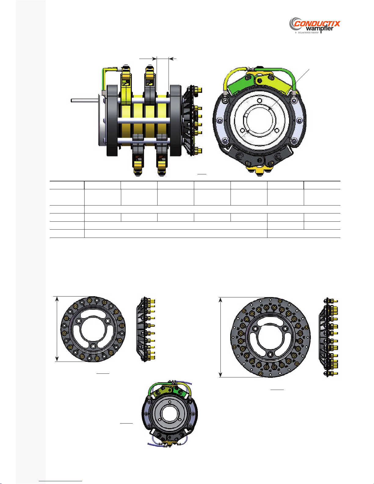
1)
Slip rings in motion (rotation), @ +30°C and duty 100%. Above 30°C, amperage value must be de-rated.
Ring type A90 B090 D090 E090 F090 U090 W090
Amperage [A]
1)
18 23 65 100 147
Analogic signals
4-20 mA
Digital signals
Bus 12 Mbps maxi
Diameter [mm] 90
Pxx [mm] 9 10 15 21 27 9 9
Ring material Brass Silver-plated brass Gold-plated brass
Brush material Copper graphite Silver graphite
Slip ring type USR090D.6.4
Connection plates
Connections of the fi xed cable cores (through the shaft) to the rings.
Several confi gurations are possible depending on the type and the number of rings.
Pxx
Ø46
Drive pin
(drum side)
Fig.9
Connections on threaded rods (≤ 48 poles)
Ø148
Fi g.10 b
Brush holder connections
Fi g.10 c
Connections on threaded rods (≤ 24 poles)
Fi g.10 a
Ø124
Page 14
SR10 | SR20 | SR30
Installation, Operating and Maintenance Instructions Manual
P. 14/40
E-360N050-0817
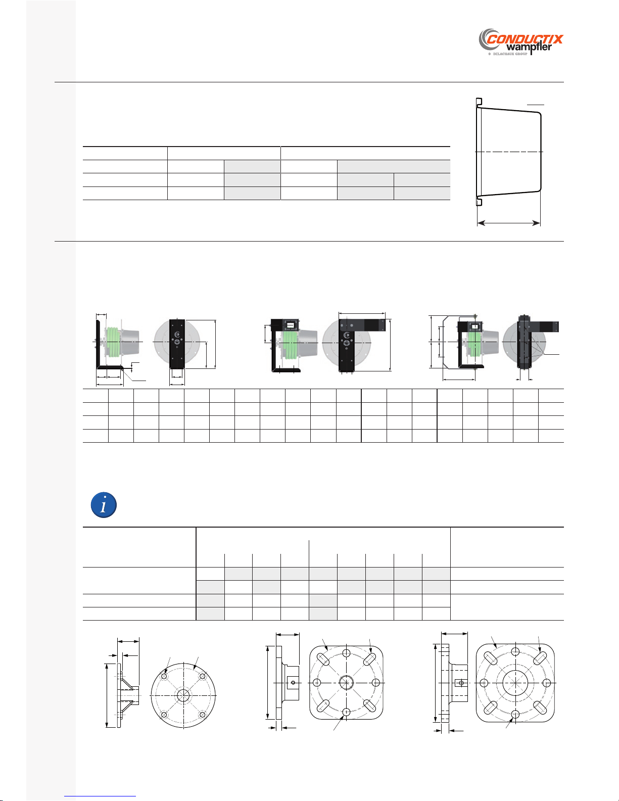
The standard reel is equipped with a slip ring housing made from impact resistant plastic.
The reel can be equipped with a steel slip ring housing (option ‘CM’).
The slip ring housing is equipped with a breather and a fl at seal
1)
and is fi xed on the drum fl ange by captive
screws.
Housing SR10 - SR20 SR30
Material Plastic Steel Plastic Steel
Outside diameter [mm] 220 220 330 300 310
L1 [mm] 129 | 159 | 209 209 | 315 159 | 209 | 314 209 | 315 450
Slip ring housingD.7
OptionsD.8
G H I J K L M N ØP Q R T U V W X Y ØZ
SR10
213 384 204 120 64 110 80 79 13 6 394 375 131 250 225 130 60 13
SR20
236 431 240 125 95 134 80 92 13 6 431 387 145 300 250 150 80 13
SR30
278 530 276 125 114 13 4 80 88 13 6 530 428 19 5 350 295 195 110 13
The adaptor fl anges ‘AB’ allow an SR reel to be fi tted in place of a reel from another range without changing the existing support. Adaptor
fl anges are delivered separately from the reel (not fi tted).
10
39
125×125
4×Ø13 /Ø100
24.5×11Ø125
Order No. 3171907
12
42
125×125
4×Ø13 /Ø100
24.5×11Ø125
Order No. 3171897
Ø115
9
39
4×Ø9 Ø98
Order No. 3194944
Steel slip ring housing ‘CM’D.8.1
See § D.7.
Brackets ‘SE’, ‘BR’ and ‘SP’D.8.2
An SR spring reel can be installed in place of an EXEL spring reel (of equivalent size) without adaptor fl ange.
1)
Glued on the slip ring housing: SR10 and SR20 | Glued on the cable drum fl ank: SR30.
Adapter fl ange ‘AB’D.8.3
N
H
G
L
M
I
JK
Q
4×ØP
Bracket ‘SE’
R
T
U
Bracket and roller guide arm ‘BR’
Y
V
X
W
W
X
3×ØZ
Swivel bracket ‘SP’
Installation of a reel... ... in place of a reel Adapter fl ange
Order No.
BEF SIRIO
15 18 22 26 0 1 2 3 4
SR10
AB15
3194944
AB18 AB26 AB00
3171907
SR20
AB18 AB22 AB26 AB01 AB02 AB03 AB04
3171897
SR30
AB18 AB22 AB26 AB01 AB02 AB03 AB04
L1
Fi g .11
Page 15
P. 15/40
E-360N050-0817
SR10 | SR20 | SR30
Installation, Operating and Maintenance Instructions Manual
Handling, packaging and storageE
HandlingE.1
Safety InstructionsE.1.1
Danger of death due to suspended loads!
During loading / unloading operations, there is a danger of death from falling parts or those swinging out of control.
Therefore:
Never step under suspended loads. Follow the specifi cations for the lifting points provided. Use only authorized lifting appliances and separate lifting accessories with suffi cient load capacity. Do not use torn or worn ropes, textile slings or straps. Do not attach ropes or straps to sharp corners and edges, and do not knot or twist them. Only move loads under supervision. Set down the load when leaving the workplace. -
WARNING
Transport inspectionE.1.2
Check the delivery for completeness and transport damage immediately upon receipt. If transport damage is externally visible, proceed as
follows:
Do not accept delivery, or accept it only with reservations. Note the scope of damage on the transport documents or on the transporter’s delivery note. File a complaint. -
Claim every defect as soon as it is detected.
Damage compensation claims may only be made within the applicable claim periods.
PackagingE.2
Only environmentally friendly materials have been used for packaging. The packaging must protect the individual components from transport
damages, corrosion, and other damage until installation.
Thus do not destroy the packaging and remove it only just before installation.
Handling packaging materials
Dispose of packaging material according to valid legal regulations and local guidelines.
Environmental damage due to improper disposal!
Packaging material is a valuable resource and can be reused, processed or recycled in many cases.
Therefore:
Dispose of packaging materials in an environmentally appropriate manner. Comply with locally applicable disposal guidelines. If necessary, engage a specialist with disposal. -
CAUTION
Possible damage from improper transport!
Improper transport can result in substantial property damage.
Therefore:
Act with care when unloading packaged parts upon delivery as well as during internal transport, and observe the symbols and the hazard information on the packaging.
Use only the attachment points provided. Wait to remove packaging material until just before installation. -
CAUTION
Risk of injury due to loads moved!
During loading / unloading operations, there is a risk of injury by crushing.
Therefore:
Always wear adequate protection: safety shoes, safety helmet, etc. -
CAUTION
Wear suitable protection equipment during all loading / unloading operations.
Helmet Safety shoes Protective gloves Work safety clothing -
Page 16
SR10 | SR20 | SR30
Installation, Operating and Maintenance Instructions Manual
P. 16/40
E-360N050-0817
Storage of packed partsE.3
Store packed parts under the following conditions:
Do not store outdoors. - Store in a dry, dust-free place. Protect from direct sunlight.
Storage temperature: +15 to +35°C, relative humidity: 60% maxi Do not expose to aggressive media. Avoid mechanical vibrations. For elastomer (e.g. seals): no ozone-generating equipment such as fl uorescent light fi xtures, mercury arc vapor lamps, or high-voltage electrical equipment may be located in the storerooms.
When storing for more than 3 months, check the general condition of all parts and the packaging at regular intervals. If necessary, add or replace the preservative.
Under some circumstances, there may be instructions for storage on the packed parts which go beyond the requirements listed
here. Follow them appropriately!
InstallationF
Danger of death from electrocution!
The product operates using voltage current. Upon contact with live components or in case of damaged insulation, there is a
danger of fatal injury.
Therefore:
Operate the system only with complete safety systems in working order! Replace loose or damaged cables and lines immediately! Avoid contact with live parts! Use insulating tools! When disconnecting the safety measures, shut the system down and secure it against unauthorized, unintentional, or accidental activation!
Check absence of voltage before starting any work on the equipment. -
DANGER
Danger of death due to suspended loads!
During loading / unloading operations, there is a danger of death from falling parts or those swinging out of control.
Therefore:
Never step under suspended loads. Follow the specifi cations for the lifting points provided. Use only authorized lifting appliances and separate lifting accessories with suffi cient load capacity. Do not use torn or worn ropes, textile slings or straps. Do not attach ropes or straps to sharp corners and edges, and do not knot or twist them. Only move loads under supervision. Set down the load when leaving the workplace. -
WARNING
Danger of death from electrocution!
The slip ring housing and its mounting on the reel are not designed to withstand external mechanical loads other than those
identifi ed for the normal operation of the installation.
Therefore:
Do not climb or walk on the slip ring housing. -
DANGER
Danger of death due to insuffi cient qualifi cations!
Improper connection of the cable can result in serious injury to person and property.
Therefore:
The installation, the crimping of the terminals on the conductors and the connection of the cables must be carried out by a trained and authorized person.
DANGER
SafetyF.1
Page 17
P. 17/40
E-360N050-0817
SR10 | SR20 | SR30
Installation, Operating and Maintenance Instructions Manual
Risk of falls!
The spring cable reel is mostly composed of rotating moving parts. The reel and its bracket are not designed to withstand
mechanical loads other than those identifi ed during normal operation of the installation.
Therefore:
Do not climb or walk on the reel. -
WARNING
Risk of injury due to poor installation!
Poor installation may result in serious personal injury and material damage.
Therefore:
Before starting the work, clear suffi cient space for assembly. Handle open components and/or those with sharp edges with care. Maintain order and cleanliness in the work area! Poorly stacked components and scattered tools are a source of accidents. Install components properly. Observe the recommended tightening torques for the screws. Place components so that they cannot fall or overturn. -
CAUTION
Personnel
Installation and initial commissioning may only be carried out by specially trained technicians!
Wear the following protective gear during all work of installation and initial commissioning:
Work safety clothing Helmet Safety shoes Protective gloves -
Danger of pinching, crushing and shearing injuries!
Locations:
Between cable and cable Between cable and drum fl anges Between cable and drum body Between rotating parts and optional bracket ‘SE’ (if supplied) Between cable and optional roller guide arm ‘BR’ (if supplied) At the pivot of the optional swivel bracket ‘SP’ (if supplied) -
Therefore:
Never work on moving parts. During installation, take protective measures (e.g. safety fence) or keep a minimum distance between rotating parts and stationary parts to rule out danger.
When disconnecting the safety measures, shut the system down and secure it against unauthorized, unintentional, or accidental activation.
CAUTION
Danger of injuries by friction and scrapes!
During operation of the system, the rotation of the reel and its projecting threaded rods and other parts may cause friction or
scrapes.
Therefore:
Do not stay near the reel and the moving parts. Take protective measures (e.g. safety fence) to keep a minimum distance from the rotating reel to rule out danger. -
CAUTION
Page 18
SR10 | SR20 | SR30
Installation, Operating and Maintenance Instructions Manual
P. 18/40
E-360N050-0817
Delivery conditionF.2
With the exception of some models SR30 with option ‘SE’,‘BR’ or ‘SP’ delivered in an open wooden crate, all spring reels are delivered in a cardboard box. The reels can be delivered in different confi gurations.
Before starting installation, the delivery must be checked for completeness and defect-free condition.
Damage to components must be reported immediately!
Check that the delivered reel corresponds to the implementation and intended use, and in particular
its winding direction. The winding direction is the opposite of the pre-tensioning (bending) direction
indicated on the fl ank of the cable drum (yellow label)
Installation of the reelF.3
HandlingF.3.1
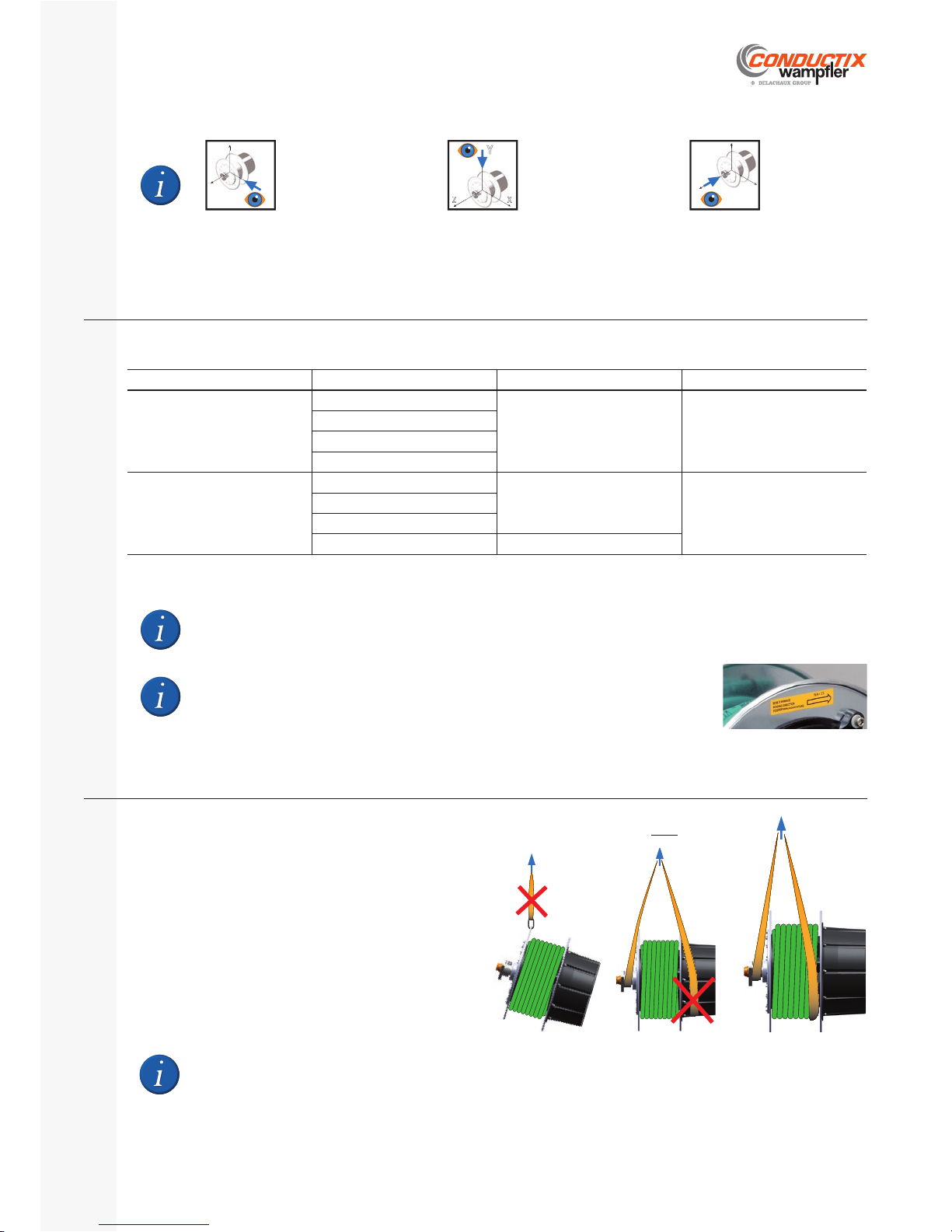
If the installation of the reel cannot be done manually, place two
textile slings according to the opposite fi gure.
The load must be balanced to avoid any slippage of the
slings.
Only use slings in good condition and of suitable length: slings
that are too short can cause deformation (cable drum fl anges).
When handling, be careful not to bump the fl anges of the cable drum: deformed fl anges do not allow a correct positioning
of the cable on the drum.
Spring reel Optional bracket Spring motor Slip ring
Supplied without cable
Without
Not pre-tensioned Not connected
‘SE’, ‘BR’ or ‘SP’ (not mounted
)
‘SP’
‘BR’ or ‘SP’
Supplied with cable
Without
Not pre-tensioned
Connected
‘SE’, ‘BR’ or ‘SP’ (not mounted
)
‘SP’
‘BR’ or ‘SP’ Pre-tensioned
Consequently some installation steps described below may not be applicable.
The images in the following chapters are accompanied by pictogram which indicates the orientation of the view.
The X axis is parallel to the laying path of the cable (retireve application).
The Z axis is perpendicular to the laying path of the cable.
Y
XZ
Top view
(acc. to Y )
X
Y
Z
Front view
(acc. to X )
Z X
Y
Side view
(acc. to Z )
Fi g.12
Page 19
P. 19/40
E-360N050-0817
SR10 | SR20 | SR30
Installation, Operating and Maintenance Instructions Manual
Risk of pinching or sectioning!
When installed with the optional swivel bracket ‘SP’, the reel is free to rotate in both directions around its axis.
Therefore:
Lock the rotation of the reel around its axis mechanically during the mounting of the swivel bracket ‘SP’. -
WARNING
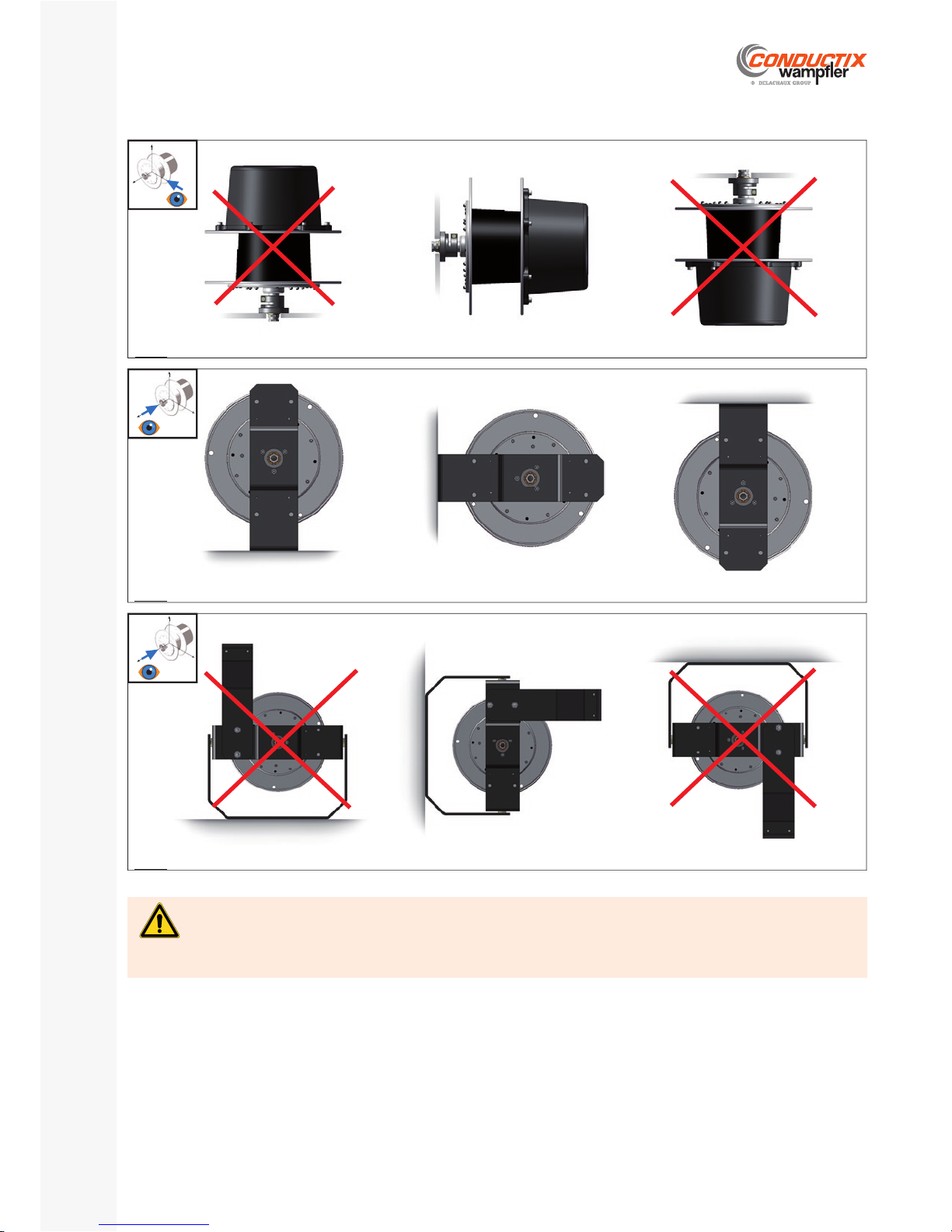
Orientation of the reelF.3.2
Reel with mounting fl ange
Floor mounting
Wall mounting
Ceiling mounting
X
Y
Z
Fi g.13 a
Optional brackets ‘SE’ or ‘BR’
Floor mounting
Wall mounting
Ceiling mounting
Z X
Y
Fi g.13 b
Optional bracket ‘SP’
Floor mounting Wall mounting
Ceiling mounting
Z X
Y
Fi g.13 c
Page 20
SR10 | SR20 | SR30
Installation, Operating and Maintenance Instructions Manual
P. 20/40
E-360N050-0817
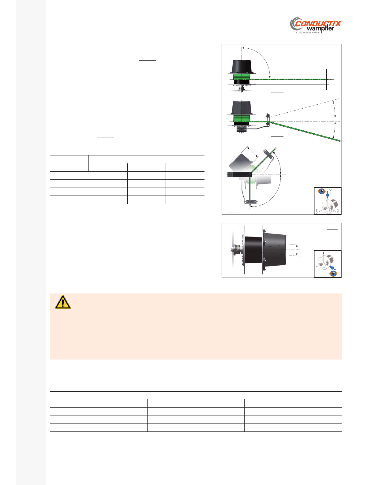
Reel with fl ange and reel with option ‘SE’
- Fig.14a
To ensure correct positioning of the cable on the drum, the rotation axis of
the reel must be perpendicular to the path of the cable.
Reel with option ‘BR’
- Fig.14b
When using a roller guide arm, the defl ection angle of the cable must be
limited to ±15° in relation to the axis of the cable path.
Cable laying pathF.3.3
Risk of injury due to poor mounting!
Inadequate or inappropriate mounting of the reel assembly can cause its fall.
Therefore:
The bracket must be rigid and suffi ciently sized to withstand the weight of the reel assembly (cable and optional bracket) as well as a maximum tension of 72 daN in the direction of the cable pay-out.
Only use screws and bolts of class 8.8 minimum. Check for the presence of spring washers under each nut. Tighten all nuts to the recommended tightening torque. All the reel mounting holes (fl ange or bracket) must be fi tted with suitable screws. -
WARNING
The reel must be fi xed:
By its mounting fl ange: Standard fl ange, see § D.3. / Adapter fl ange ‘AB’ option, see § D.8.2. By the bracket ‘SE’ or the swivel bracket ‘SP’ (optional): see § D.8.1. -
Rotation axisF.3.4
The rotation axis of the reel must be horizontal and within the tolerances
shown on fi g.15.
FasteningsF.3.5
Reel with option ‘SP’
- Fig.14c
The maximum swivelling angle ß° of the reel is limited by the length of the
slip ring housing, according to the table below:
L1 housing
1)
[mm]
E [mm] / ß° maxi
SR10 SR20 SR30
129 137 / 90 137 / 90 159 167 / 55 167 / 90 170 / 90
209 217 / 55 217 / 60 220 / 50
314 - - 336 / 50
1)
See § D.7.
Tightening torque and preload of the metric thread screws, quality 8.8
Diameter × Pitch Preload [N] Tightening torque Cs [Nm]
M8 × 1.25 15 240 23
M10 × 1.5 24 275 52
M12 × 1.75 35 400 79
For 90% of use at 0.2% of the elastic limit.
ISO thread, average friction coeffi cient µ = 0.15
90°
==
15° maxi
15° maxi
90°
ß°
E
Y
XZ
Fi g.14a
Fi g.14b
Fig.14c
5° max
1° max
X
Y
Z
Fi g.15
Page 21
P. 21/40
E-360N050-0817
SR10 | SR20 | SR30
Installation, Operating and Maintenance Instructions Manual
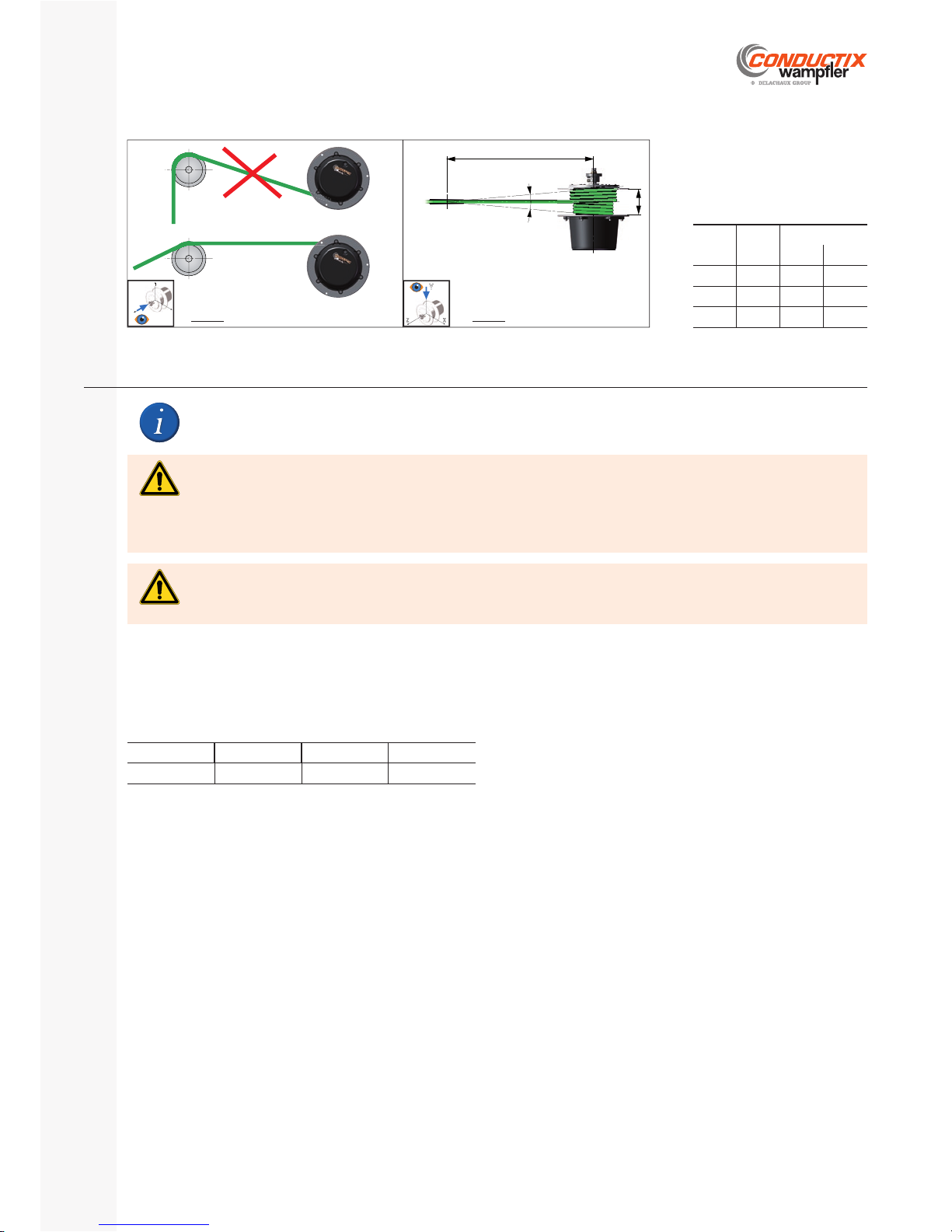
Use with defl ecting pulleyF.3.6
Type
G
[mm]
A [mm]
3° 5°
SR10
114 1100 650
SR20
129 1240 750
SR30
179 1700 1050
3-5°
3-5°
G
A
Y
XZ
Z X
Y
If the reel is supplied with its wound cable installed and connected, go directly to § F.5
Installation of the wound cableF.4
Cable lengthF.4.1
The total length of the cable should be:
Cable length = working length + ∆L
with : ∆ L = 1 safety turn (always wound on the drum) + length required for the connections to slip rings and to the fi xed point
Type SR10 SR20 SR30
∆ L [m] 2 2 3
Caution!
Protective means of the conductors such as fuses and/or magneto-thermal circuit breakers and cut-out in the event of a fault
should be installed by the customer according to the rules in force.
CAUTION
Risk of injury due to incorrect installation!
At least one turn of cable (‘safety turn’) must always be wound on the drum.
Therefore:
Never unwind the cable beyond the limit defi ned for the application, up to blockage of the springs. This can cause damage to the springs and the breakage of the reel mounting fl ange.
WARNING
Installation on the cable drumF.4.2
Turn the drum manually in the direction on the winding label until blockage. - Do not force beyond this limit.
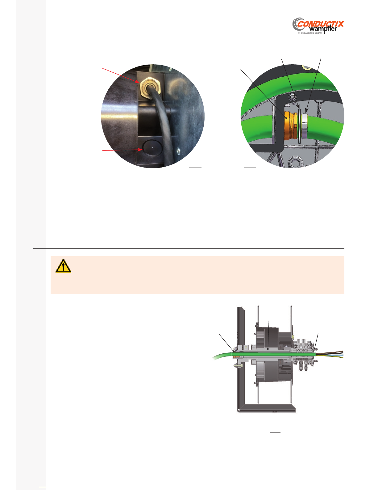
Immobilise the drum in this position mechanically. Remove the slip ring housing. Insert a suffi cient length of cable into the cable gland to allow electrical connection of the conductors to the brush holders of the slip ring assembly.
Tighten the cable gland. Install a Mu washer and a STAUBLI (or equivalent) locking collar on the cable (on the inner side of the cable drum) and press it onto the cable gland.
Fi g.16 a Fi g.16 b
Page 22
SR10 | SR20 | SR30
Installation, Operating and Maintenance Instructions Manual
P. 22/40
E-360N050-0817
Hold the cable fi rmly before releasing the cable drum. Slowly wrap the cable using the action of the springs. Guide the cable so that the fi rst turn is applied against the drum fl ange, then the next turns against each other without overlapping
Proceed with the connection of the conductors on the slip ring brush holders : see § F.6.1. Refi t the slip ring housing with its fl at gasket. -
Installation of the fi xed cableF.5
The cable glands supplied with the reel are intended to hold the cable, not to eliminate a tension applied to the cable. It is up to the
integrator to ensure that no force is transmitted by the cable to the cable gland.
Therefore:
Do not exert a force tending to extract or to bend the fi xed cable at the cable gland. If such a force occurs, attach the cable so that no force is applied to the cable gland.
CAUTION
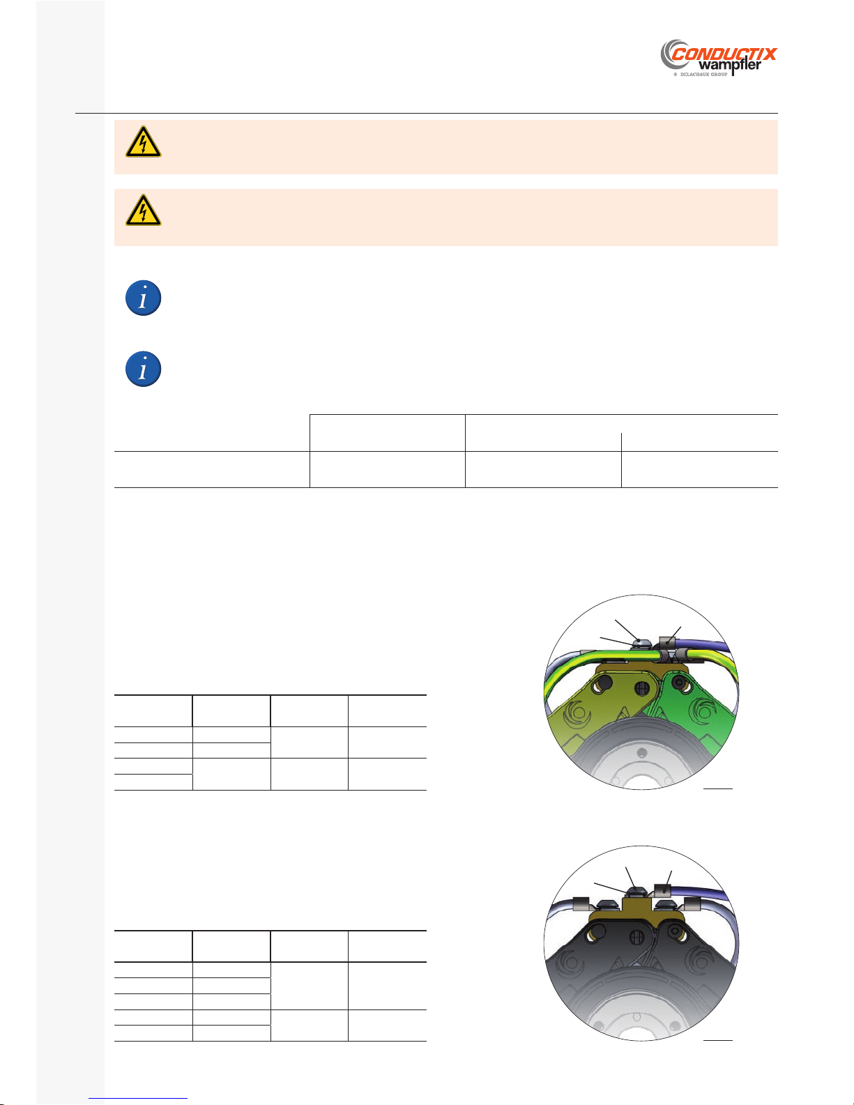
Remove the slip ring housing and its gasket. Insert the cable in the cable gland - (1) and then into the hollow
shaft of the reel (2) beyond the connection plate of the slip ring
(3).
Make the connections to the slip rings: see § F.6.2. Before tightening the cable gland at the end of the shaft, pull the cable back gently to absorb any excess length of the
conductors.
Refi t the slip ring housing with its gasket. -
1
2
3
(Optional bracket ‘SE’)
Cable gland location
Clockwise winding direction
Cable gland location
Counterclockwise
winding direction
Fi g. 17a
Washer Mu
«STAUBLI»
type collar
Cable gland
Fi g. 17b
Fi g.18
Page 23
P. 23/40
E-360N050-0817
SR10 | SR20 | SR30
Installation, Operating and Maintenance Instructions Manual
Danger of death by electrocution!
The earth ring must always be connected to the earth of the installation. This can be done via the cable of the reel or via a
specifi c conductor if the cable does not have an earth conductor. It must be colored green / yellow and be clearly identifi able.
DANGER
Slip ring connectionsF.6
Danger of death by electrocution!
Never disconnect the earth shunt between the slip ring and the drum fl ange.
DANGER
Use only insulated terminals or ferrules, preferably made from poly carbonate (for temperature resistance). The terminals or ferrules should be crimped with suitable tools according to the section of the conductors.
The rules and installation recommendations of the manufacturer of the terminals must be respected.
Operators must be certifi ed.
Brush holder Connection plate
On threaded rods On terminal blocks
Max. number of lugs
per connection point
4
1)
3
1)
1 (ferrule)
1)
Position the lugs so as not to bend them.
Connections to the brush holders (wound cable)F.6.1
The brush holders are provided with screws and washers (cable and terminals by others).
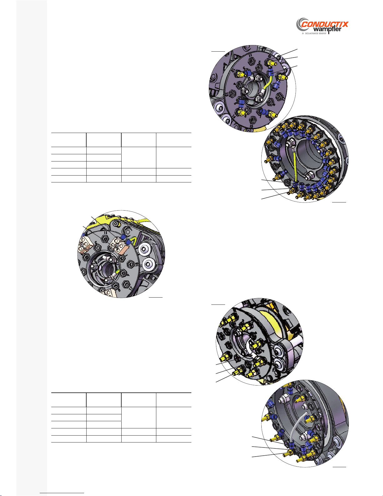
Earth brush holder
Prepare the G/Y conductor of adequate section and length and crimp on an insulated connection lug.
Remove the screw - (1) and the washer (2)
Fit the lug - (3)
Refi t the washer and the screw and tighten to the recommended torque.
1
3
2
Ring type
Cond. section
[mm²]
Screw dia.
re p.1
Tightening
torque [Nm]
A
max .1.5
M4 1.5
B
max. 4
D
max. 10 M6 3.0
E
Each shield must be connected to a specifi c ring of the slip ring, not shared with other earth or shield connections.
Power and control brush holders
Prepare each conductor of adequate section and length and crimp on an insulated connection lug.
Remove the screws - (1) and the washer (2)
Fit the lugs - (3)
Refi t the washer and the screw and tighten to the recommended torque.
Ring type
Cond. section
[mm²]
Screw dia.
re p.1
Tightening
torque [Nm]
U or W
0.5
M4 1.5
A
1.5
B
4
D
10
M6 3.0
E
10 (×2)
2
1
3
Fi g.19 a
Fi g.19 b
Page 24
SR10 | SR20 | SR30
Installation, Operating and Maintenance Instructions Manual
P. 24/40
E-360N050-0817
Connections to the rings (fi xed cable)F.6.2
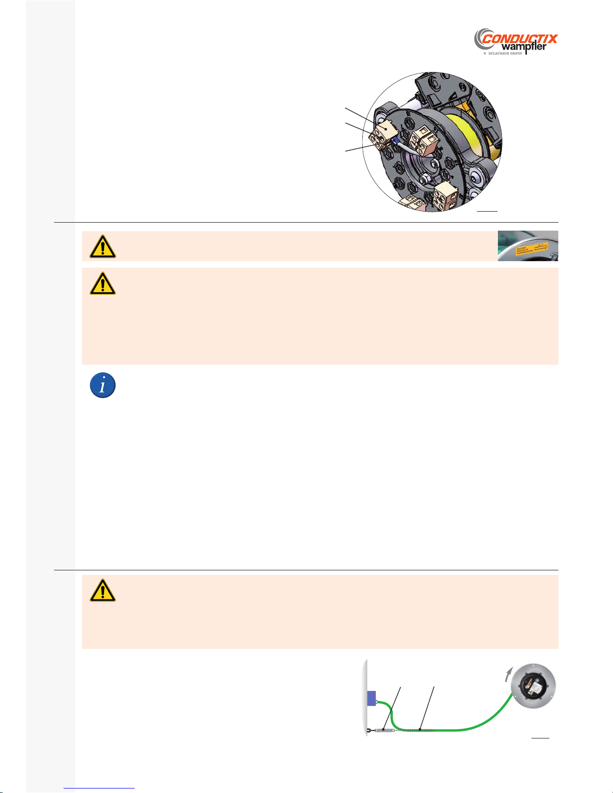
The threaded rods are provided with nuts and washers (cables and
lugs by others).
Earth conductor on threaded rod
Prepare the G/Y conductor of adequate section and length and crimp on an insulated connection lug.
Remove the nut - (1) and the washer (2)
Fit the lug - (3) on the threaded rod.
Refi t the washer and the nut and tighten to the recommended torque.
Ring type
Cond. section
[mm²]
Screw dia.
re p.1
Tightening
torque [Nm]
U or W
0.5
M4 1.5
A
1.5
B
4
D
10 M5 2.0
E
10 (×2) M5 (×2) 2.0
2
1
3
Type USR050
Type USR090
2
1
3
Earth conductor on connection terminal (USR050)
Prepare the G/Y conductor of adequate section and length and crimp on an insulated connection terminal.
Loosen the bolt - (1) of the terminal block (2)
Fit the terminal in the terminal block. Tighten the terminal block screw -
2
1
Power and control conductors on threaded rod
Prepare each conductor of adequate section and length and crimp on an insulated connection lug.
Remove the nut - (1) and the washer (2)
Fit the lug - (3) on the threaded rod.
Refi t the washer and the nut and tighten to the recommended torque Cs.
Ring type
Cond. section
[mm²]
Screw dia.
re p.1
Tightening
torque [Nm]
U or W
0.5
M4 1.5
A
1.5
B
4
D
10 M5 2.0
E
10 (×2) M5 (×2) 2.0
Type USR050
2
1
3
1
Type USR090
2
3
Fig.20a
Fig.20b
Fig.20c
Fig.20d
Fig.20e
Page 25
P. 25/40
E-360N050-0817
SR10 | SR20 | SR30
Installation, Operating and Maintenance Instructions Manual
Power and control conductors on terminal blocks (USR050)
Prepare each conductor of adequate section and length an crimp on an insulated connection terminal.
Loosen the screw - (1) of the corresponding terminal block (2)
Fit the ferrule - (3) in the terminal block.
Tighten the terminal block screw. -
2
1
3
Pre-tensioning of the spring motorF.7
The reels equipped with a cable stop (options ‘BR’ and ‘SP’) are delivered with the spring motor pre-tensioned.
Risk of injury by impact, rubbing or shearing!
The reel is equipped with powerful springs. If the cable drum is released while the springs are bent, it rotates at high speed, in
an uncontrolled manner, until the springs are relaxed.
Therefore:
Prevent the cable unwinding during the springs pre-tensioning phase. Prevent a sudden release of the tension of the springs. Do not attempt to stop the rotation of the cable drum with your hands. Wear protective gloves. -
WARNING
The cable is wound on the reel drum, with the free end of the cable attached to the drum by means of a cord. The reel is blocked in rotation. To obtain the initial tension of the spring motor or BENDING: -
Rotate the drum and the cable in the direction of rotation indicated by the arrow on the yellow labelon the side of the drum. Perform the number of revolutions (‘NA’) indicated on the yellow label on the side of the drum. -
It is imperative to respect the number of pre-tensioning (bending) turns ‘NA’
indicated on the yellow label!
Detach the cord to release the end of the cable. Remove a cable length equal to - ∆ L / 2 from the drum without rotating it (see § F.4.1.)
Note: In some cases, an extra length of cable is provided for connection to the attachment point. Also remove this extra cable length from
the drum without rotating it.
Grasp the cable end and move it to the anchor point (release the rotation of the drum and pay out the cable normally). Attach the cable end with a cable grip and a spring impact absorber (see § F.8.).
Securing of the cable to the anchor pointF.8
Construction of the anchor point
There are different solutions for the construction of the anchor point. The
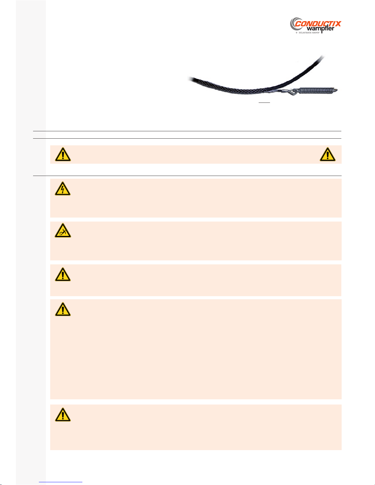
absorption of the tension and the return are handled by a cable grip (suitable for horizontal or vertical cables).
Cable grip (mesh)1.
Spring impact absorber2.
2 1
Danger of injury by impact, and getting caught up!
In the event of sudden failure of the anchor point, the spring reel pulls the cable back at high speed which causes a whiplash
effect that is dangerous for people and equipment in the vicinity.
Therefore:
The anchor point must be suffi ciently sized and secured to resist the permanent tensile forces generated by the reel and the cable.
WARNING
Fig.20f
Fig.21
Winding
direction 1
Page 26
SR10 | SR20 | SR30
Installation, Operating and Maintenance Instructions Manual
P. 26/40
E-360N050-0817
The cable anchor point must be located on the axis of the drum (see § F.3.3)
To install the cable grip - (1), compress it slightly before
sliding and positioning it around the cable. Provide
enough cable to have an “S” shaped loop before the
connection box.
Attach the cable grip to the spring impact absorber - (2)
Make the electrical connection of the cable to the anchor point.
CommissioningG
Risk of injury due to poor commissioning!
Commissioning carried out incorrectly can lead to dangerous situations for users.
Therefore:
Before commissioning perform the tests on the manufacturer’s check-list. -
WARNING
This equipment is not designed to be used in EXplosive ATmospheres (ATEX)
in accordance with the defi nition in directive 2014/34/UE dated 29 march 2014
Danger of death by electrocution!
The slip ring housing and its mounting on the reel are not designed to withstand external mechanical loads other than those
identifi ed for the normal operation of the installation.
Therefore:
Do not climb or walk on the slip ring housing. -
DANGER
Risk of falls!
The spring cable reel is mostly composed of rotating moving parts. The reel and its bracket are not designed to withstand
mechanical loads other than those identifi ed during normal operation of the installation.
Therefore:
Do not climb or walk on the reel. -
WARNING
Danger of injuries by friction and scrapes!
During operation of the system, the rotation of the reel and its projecting threaded rods and other parts may cause friction or
scrapes.
Therefore:
Do not stay near the reel. Take protective measures (e.g. safety fence) to keep a minimum distance from the rotating reel to rule out danger. -
CAUTION
SafetyG.1
Fig.22
Danger of pinching, crushing and shearing injuries!
Locations:
Between cable and cable Between cable and drum fl anges Between cable and drum body Between rotating parts and optional bracket ‘SE’ (if supplied) Between cable and optional roller guide arm ‘BR’ (if supplied) At the pivot of the optional swivel bracket ‘SP’ (if supplied) -
Therefore:
Never work on moving parts. During commissioning, take protective measures (e.g. safety fence) or keep a minimum distance between rotating parts and stationary parts to rule out danger.
When disconnecting the safety means, shut the system down and secure it against unauthorized, unintentional, or ac- cidental activation.
CAUTION
Page 27
P. 27/40
E-360N050-0817
SR10 | SR20 | SR30
Installation, Operating and Maintenance Instructions Manual
Operation testsG.4
The commissioning of the reel is performed jointly with the user of the system and is documented. All the staff required for the commissioning
(operators, electricians and installation technicians) must be made available by the user of the system for the whole duration of the operation.
Free access to the system must be provided. Once the commissioning is completed, Conductix-wampfl er will receive from the user a protocol
of fi nal acceptance in which it is stipulated that the system meets the requirements of the application.
General informationG.2
Check if the characteristics of the spring reel are compatible with the use, especially if the section of cable conductors is compatible with the current consumed by the mobile unit fed taking into account the de-rating factors below.
Check that the maximum current of the cable is lower than the current capacity of the slip rings. Check that the electrical circuit is properly protected. Check the continuity of the earth. Make sure that the operators are trained in the use of the spring reel. -
Section [mm²] 1 1.5 2.5 4 6 10 16
Amperage [A] 15 20 25 35 45 63 84
Derating factor according to the number of conductors (< 10 mm²)
No. of conductors 4 5 7 12 18 24
Factor 1 0.75 0.65 0.53 0.44 0.40
Derating factor according to the ambient temperature
Temperature [°C] 30 40 50 55 60
Factor 1 0.90 0.80 0.74 0.65
Use with max. voltage 690 V-AC or 600 V-DC
Max. amperage for one conductor (in operation @+30°C, 100% duty)
Perform complete translations with stopping and starting.
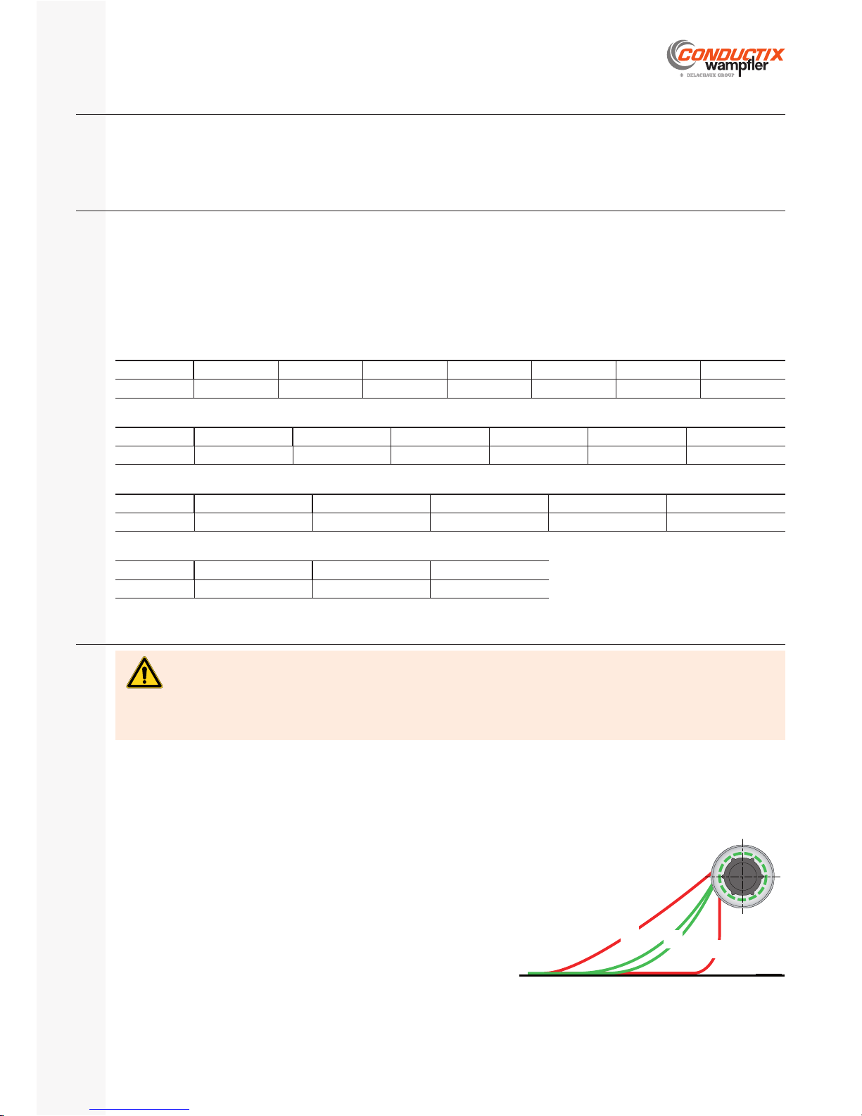
During the fi rst test, it is necessary to check that the cable winds up cor-
rectly on the drum, without torsion, over the entire length of the travel.
The cable must form a slight curve during the winding and unwinding ac-
cording to the opposite fi gure.
A: Excessive tensile pull in the cable
B: Correct tensile pull
C: Insufficient tensile pull in the cable
In the event of a fault, investigate the cause by referring to § I. «Troubleshooting».
Check-list before commissioningG.3
Unwind the cable from the reel completely by hand, including the safety turn. If everything is correct, wind up the cable. If the drum blocks
and there is still some cable on it:
Count the number of remaining spires of cable on the drum, Redo the pre-tensioning procedure of the spring motor reducing the number of turns ‘NA’ by the number of remaining turns. -
Risk of injury due to incorrect installation!
At least one turn of cable (‘safety turn’) must always be wound on the drum.
Therefore:
Never unwind the cable beyond the limit defi ned for the application, up to blockage of the springs. This can cause damage to the springs and the breakage of the reel mounting fl ange.
WARNING
A
B
C
Fig.23
Derating factor for multi-layers of cable
No. of layers 1 2 3+
Factor 1.00 0.80 0.65
Page 28
SR10 | SR20 | SR30
Installation, Operating and Maintenance Instructions Manual
P. 28/40
E-360N050-0817
OperationH
Danger of injury due to improper operation!
Improper operation can result in serious injury to person and property.
Therefore:
Carry out all operating steps according to the specifi cations of these operating instructions. Before starting work, be sure that all covers and safety systems are installed and working properly. Never disable the safety systems during operation. Maintain order and cleanliness in the working area! Loosely stacked or scattered components and tools are a source of accidents.
WARNING
Danger for unauthorized personnel!
Unauthorized personnel who do not meet the requirements described here do not understand the danger in the working area.
Therefore:
Keep unauthorized personnel away from the working area. In case of doubt, address the person and direct them away from the working area. Stop work as long as unauthorized personnel is in the working area. -
WARNING
Danger of death from electrocution!
The cable must be able to wind and unwind freely, without contact or external friction that could damage its insulation.
Therefore:
Do not drive or walk on the cable. Do not place a load on the cable. Check visually the general condition of the cable regularly (insulating sheath). -
WARNING
Danger due to entanglement!
During operation of the system, the rotation of the reel and its projecting threaded rods and other parts can pick up and drag
surrounding objects.
Therefore:
Do not stay near the reel. During operation, take protective measures (e.g. safety fence) or keep a minimum distance from the rotating reel to rule out danger.
WARNING
Danger of injury due to improper operation!
The cable must be able to wind and unwind freely, without external mechanical loading that could damage or break it suddenly
(risk of ‘whiplash’).
Therefore:
Before every operation, check that the cable track is free of any source of blocking or friction. Check that there are no sharp edges in the vicinity of the cable.
Check visually the general condition of the cable regularly (insulating sheath). -
WARNING
Risk of tripping!
During operation of the system, there is a risk of tripping resulting in injury due to the movement of the wound cable.
Therefore:
During operation, keep a safety distance from the cable deposit track. -
WARNING
Danger of death from electrocution!
The slip ring housing and its mounting on the reel are not designed to withstand external mechanical loads other than those
identifi ed for the normal operation of the installation.
Therefore:
Do not climb or walk on the slip ring housing. -
DANGER
SafetyH.1
Page 29
P. 29/40
E-360N050-0817
SR10 | SR20 | SR30
Installation, Operating and Maintenance Instructions Manual
OperationH.2
The operation of the spring reel is fully automatic. No action is necessary on the product during normal and usual use.
Danger of pinching, crushing and shearing injuries!
Locations:
Between cable and cable Between cable and drum fl anges Between cable and drum body Between rotating parts and optional bracket ‘SE’ (if supplied) Between cable and optional roller guide arm ‘BR’ (if supplied) At the pivot of the optional swivel bracket ‘SP’ (if supplied) -
Therefore:
Never work on moving parts. During operation, take protective measures (e.g. safety fence) or keep a minimum distance between rotating parts and stationary parts to rule out danger.
When disconnecting the safety measures, shut the system down and secure it against unauthorized, unintentional, or accidental activation.
CAUTION
Danger of injuries by friction and scrapes!
During operation of the system, the rotation of the reel and its projecting threaded rods and other parts may cause friction or
scrapes.
Therefore:
Do not stay near the reel and the moving parts. Take protective measures (e.g. safety fence) to keep a minimum distance from the rotating reel to rule out danger. -
CAUTION
Risk of falls!
The spring cable reel is mostly composed of rotating moving parts. The reel and its bracket are not designed to withstand
mechanical loads other than those identifi ed during normal operation of the installation.
Therefore:
Do not climb or walk on the reel. -
WARNING
Personnel
The equipment can only be used by qualifi ed personnel.
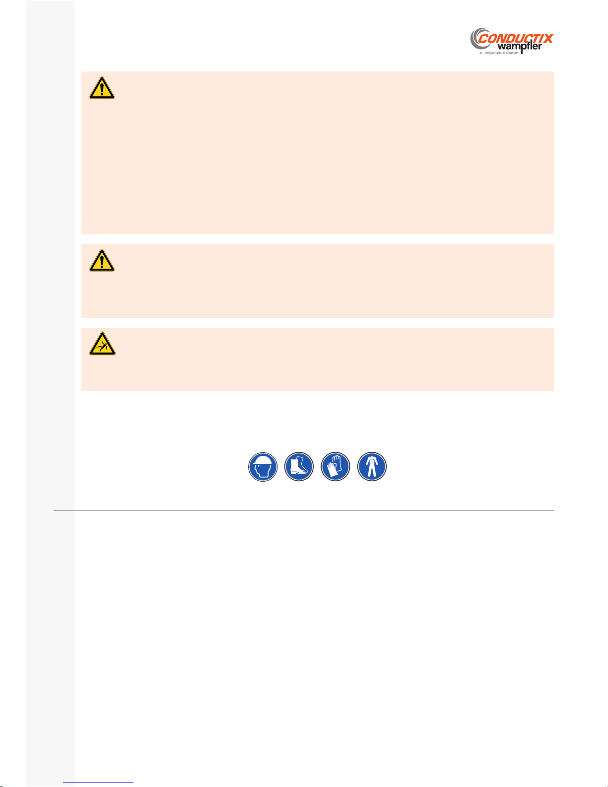
Personal protection equipment (must be worn during all jobs):
Work safety clothing Helmet Safety shoes Protective gloves -
Page 30
SR10 | SR20 | SR30
Installation, Operating and Maintenance Instructions Manual
P. 30/40
E-360N050-0817
TroubleshootingI
Danger of injuries due to improper troubleshooting!
Improper troubleshooting can result in serious injury to person and property.
Therefore:
Contact the manufacturer in case of malfunction. Allow troubleshooting to be carried out only by personnel from or authorized by the manufacturer. -
WARNING
Danger of burns!
During (or just after) operation, certain parts or external surfaces of the reel can be hot.
The slip ring assembly is a component that heats up in normal operation, regardless of the rotation of the reel.
Therefore:
Wear suitable protection equipment before any intervention on the spring reel. Before any intervention on the slip rings, check that its constituent parts are not hot before touching them. -
WARNING
Risk of cuts and sectioning!
The spring motor is dangerous component. It is not designed to be replaced. The direct accessibility of the springs is prevented
by a closing fl ange and by captive screws.
Therefore:
Do not attempt to remove the screws. Do not attempt to access the springs directly by any means. -
WARNING
Risk of injury by pinching!
The slip ring assembly is a rotating electrical component.
Therefore:
Before starting any intervention on the slip ring assembly: make sure that it cannot rotate unexpectedly. -
WARNING
Risk of bodily harm!
In the event of unexpected jamming of the cable, there is a risk of ‘whiplash’.
Therefore:
Evacuate the area. Identify and remove the jam with caution. -
WARNING
SafetyI.1
Danger of death from electrocution!
The equipment is fed by an electric current. Upon contact with live components or in case of damaged insulation, there is a
danger of fatal injury.
Therefore:
Operate the system only with complete safety systems in working order! Replace loose or damaged cables and lines immediately! Avoid contact with live parts! Use insulating tools! Before disconnecting the safety measures, shut the system down and secure it against unauthorized, unintentional, or accidental activation!
Check absence of voltage before starting any work on the equipment. -
DANGER
Danger of death from electrocution!
The slip ring housing and its mounting on the reel are not designed to withstand external mechanical loads other than those
identifi ed for the normal operation of the installation.
Therefore:
Do not climb or walk on the slip ring housing. -
DANGER
Risk of falls!
The spring cable reel is mostly composed of rotating moving parts. The reel and its bracket are not designed to withstand
mechanical loads other than those identifi ed during normal operation of the installation.
Therefore:
Do not climb or walk on the reel. -
WARNING
Page 31
P. 31/40
E-360N050-0817
SR10 | SR20 | SR30
Installation, Operating and Maintenance Instructions Manual
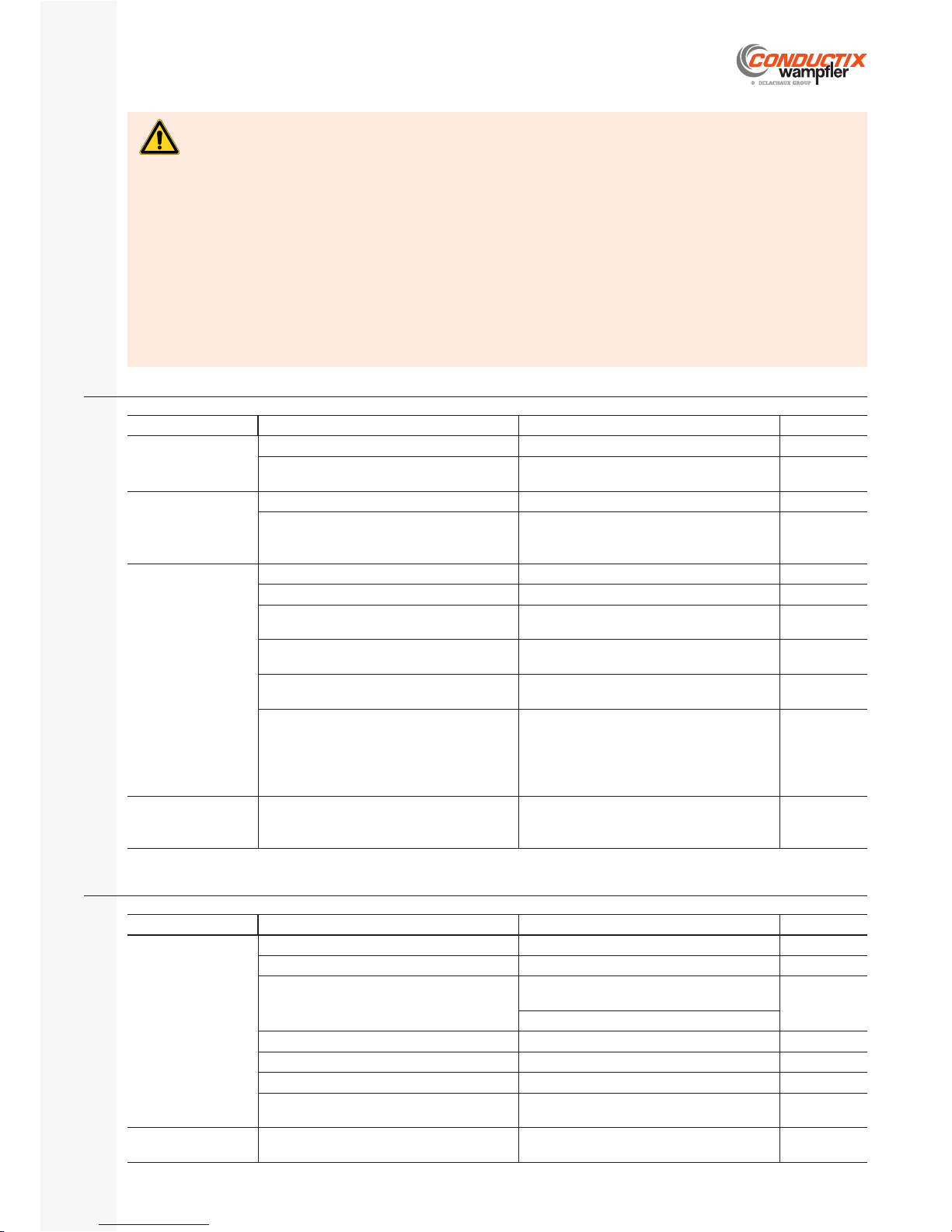
Mechanical disturbance Possible cause Elimination
See
Electrical fault Connection to the brush holders - Tighten the connections screws -
§ F.6.1.
Internal connection of the rings - Contact Conductix-Wampfler -
-
Rapid wear of the brushes - Check the condition of the contact surface -
of the ring
§ J.3.3.
Replace the complete brush holder -
Destroyed or pitted rings - Replace the complete slip ring assembly -
-
Short-circuits and/or electric shocks - Contact Conductix-Wampfler -
-
Presence of soiling - Clean using a light jet of dry air -
-
Presence of condensation - Check the effi ciency of the anti-condensation -
heating, if it is exists.
-
Mechanical fault Diffi cult and/or noisy rotation - Check the condition of the bearings -
Replace the slip ring assembly if necessary -
-
Mechanical disturbance Possible cause Elimination
See
Absence of safety
turn at travel end
Cable too short - Replace the cable. - § F.4.1.
Cable used in excess at the anchor point - Retrieve a suffi cient length of cable from the -
anchor point
§ F.8.
Tension too low
during winding
Incorrect pre-tensioning of spring motor - Check. Correct if necessary. - § F.7.
Check the actual conditions of operation -
(height, speed, run-up time)
Correct variations. -
In the event of impossibility, contact
Conductix-wampfl er
-
Incorrect storage
positioning of the
cable on the drum
Reel rotation axis not horizontal - Correct / shim the reel bracket - § F.3.4.
Reel axis not perpendicular to the travel - Correct / shim the reel bracket - § F.3.3.
Cable anchor point off centre. - Align the cable anchor point and the axis of -
the cable drum
§ F.3.3.
Poor positioning during winding of the fi rst layer of cable on the drum
Wind up the cable by forcing the fi rst coil against the fl ange of the cable drum
§ F.4.2.
Sticky cable - Unwind and clean the cable over its entire -
length (cloth + water)
-
Cable too ‘nervous’, pre-stressed cable - Secure the drum so that it cannot turn but so -
that all the cable is unwound.
Disconnect the cable at the anchor point and lay it on the ground to stabilize
Help it by turning it by hand if necessary. -
-
Impossible to unwind
the cable over the
entire travel
Incorrect pre-tensioning of the spring motor - Disconnect the cable at the anchor point. -
Redo the entire pre-tensioning procedure -
§ F.7.
Spring reel and cableI.2
Slip ringsI.3
Danger of pinching, crushing and shearing injuries!
Locations:
Between cable and cable Between cable and drum fl anges Between cable and drum body Between rotating parts and optional bracket ‘SE’ (if supplied) Between cable and optional roller guide arm ‘BR’ (if supplied) At the pivot of the optional swivel bracket ‘SP’ (if supplied) -
Therefore:
Never work on moving parts. During maintenance, take protective measures (e.g. safety fence) or keep a minimum distance between rotating parts and stationary parts to rule out danger.
Before disconnecting the safety measures, shut the system down and secure it against unauthorized, unintentional, or accidental activation.
CAUTION
Page 32
SR10 | SR20 | SR30
Installation, Operating and Maintenance Instructions Manual
P. 32/40
E-360N050-0817
MaintenanceJ
SafetyJ.1
Risk of injury due to poor maintenance!
Faulty servicing may result in serious personal injury and material damage.
Therefore:
Before starting the work, clear suffi cient space for assembly. Maintain order and cleanliness in the assembly area! Poorly stacked components and scattered tools are a source of accidents.
If components have been removed, be sure to reinstall them correctly, to replace all the fastenings and comply with the recommended tightening torques for screws.
After the maintenance operations, reinstall all safety covers and all the locks. -
WARNING
Danger of death from electrocution!
The equipment is fed by an electric current. Upon contact with live components or in case of damaged insulation, there is a
danger of fatal injury.
Therefore:
Operate the system only with complete safety systems in working order! Replace loose or damaged cables and lines immediately! Avoid contact with live parts! Use insulating tools! Before disconnecting the safety measures, shut the system down and secure it against unauthorized, unintentional, or accidental activation!
Check absence of voltage before starting any work on the equipment. -
DANGER
Danger of death from electrocution!
The slip ring housing and its mounting on the reel are not designed to withstand external mechanical loads other than those
identifi ed for the normal operation of the installation.
Therefore:
Do not climb or walk on the slip ring housing. -
DANGER
Danger of death due to suspended loads!
During loading / unloading operations, there is a danger of death from falling parts or those swinging out of control.
Therefore:
Never step under suspended loads. Follow the specifi cations for the lifting points provided. Use only authorized lifting appliances and separate lifting accessories with suffi cient load capacity. Do not use torn or worn ropes, textile slings or straps. Do not attach ropes or straps to sharp corners and edges, and do not knot or twist them. Only move loads under supervision. Set down the load when leaving the workplace. -
WARNING
Risk of falls!
The spring cable reel is mostly composed of rotating moving parts. The reel and its bracket are not designed to withstand
mechanical loads other than those identifi ed during normal operation of the installation.
Therefore:
Do not climb or walk on the reel. -
WARNING
Danger of injuries by friction and scrapes!
During operation of the system, the rotation of the reel and its projecting threaded rods and other parts may cause friction or
scrapes.
Therefore:
Do not stay near the reel and the moving parts. Take protective measures (e.g. safety fence) to keep a minimum distance from the rotating reel to rule out danger. -
CAUTION
Page 33
P. 33/40
E-360N050-0817
SR10 | SR20 | SR30
Installation, Operating and Maintenance Instructions Manual
Maintenance scheduleJ.2
In order to keep the warranty rights and to avoid damage to the equipment, the system operator is responsible for the execution of the following
maintenance tasks. The maintenance tasks must be performed by trained and qualifi ed technicians.
The following sections describe the maintenance tasks required for optimized and problem-free functioning.
If, in the course of regular checks, wear appears faster than expected, the corresponding maintenance intervals should be shortened to take
into account the actual fi ndings of wear.
For all questions concerning the maintenance operations and intervals, contact the manufacturer.
Danger of death from electrocution!
The equipment is fed by an electric current. Upon contact with live components or in case of damaged insulation, there is a
danger of fatal injury.
Therefore:
After any operation on the reel, the continuity of the equipotential protection circuit must be checked (according to EN60204-1). The permissible voltage drop must be less than 1V with a stabilized current of 10A.
DANGER
ServicingJ.3
CleaningJ.3.1
CableJ.3.2
Periodically check:
The cable geometry: weaving, snaking. Replace the cable if necessary. The outer sheath of the cable: abrasion or perforation. It must not be sticky. Clean if necessary. -
Danger of death from electrocution!
The equipment is fed by an electric current. Upon contact with live components or in case of damaged insulation, there is a
danger of fatal injury.
Therefore:
Switch power off before cleaning the spring reel. Do not use a high pressure cleaner. -
DANGER
Danger of pinching, crushing and shearing injuries!
Locations:
Between cable and cable Between cable and drum fl anges Between cable and drum body Between rotating parts and optional bracket ‘SE’ (if supplied) Between cable and optional roller guide arm ‘BR’ (if supplied) At the pivot of the optional swivel bracket ‘SP’ (if supplied) -
Therefore:
Never work on moving parts. During maintenance, take protective measures (e.g. safety fence) or keep a minimum distance between rotating parts and stationary parts to rule out danger.
Before disconnecting the safety measures, shut the system down and secure it against unauthorized, unintentional, or accidental activation.
CAUTION
Page 34
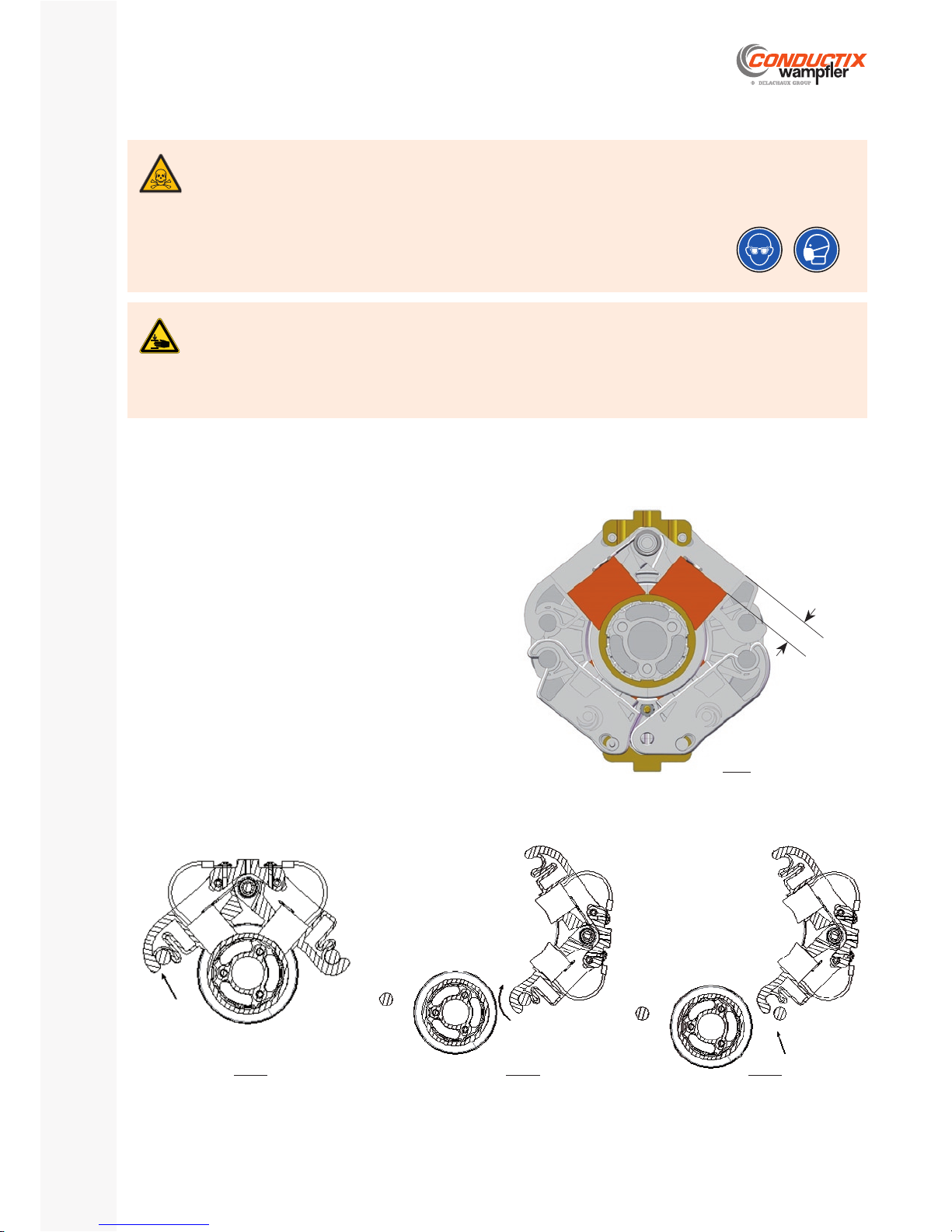
SR10 | SR20 | SR30
Installation, Operating and Maintenance Instructions Manual
P. 34/40
E-360N050-0817
Risk of injury by crushing!
Location: brush holders
Therefore:
Before unlocking, removing, or inserting and locking the brush holders, make sure that there is no possible relative rotation between the brush holders and the rings and the terminal block.
If necessary, use appropriate protection gloves. -
CAUTION
Risk of reaction, irritation of the mucous membranes and respiratory disease due to dust!
The residues of abrasion of the contact brushes accumulate in the slip ring body. This dust is very fi ne and presents a health
risk.
Therefore:
During cleaning, wear a suitable equipment: safety glasses and an FFP3 class mask. Do not blow the dust with compressed air, but rather vacuum it up. The vacuum cleaner must be equipped with a fi ne class H fi lter.
Do not eat, drink or smoke during work! -
Replacement of the brush holders
The fi rst restart after maintenance must be performed without the slip ring housing and without transmission of electrical energy and / or
signals, in order to observe the correct rotation of the rings.
Depending on the limit that is reached fi rst, perform the regular maintenance after:
One million revolutions; One year of operation; A machine shut down of at least two months. -
X
Procedure
Check the contact surface of the rings (if necessary, clean using a very dry cloth);
Remove the dust from the insulating spacers between the rings; Clean the rings using a light jet of dry air; Check the connections; Check tightening of bolts and threaded rods of the rings; Check the condition and the cleaning of brushes; Check the wear of the brushes: replacement if X - ≥ 20 mm
(opposite fi g.)
Slip ringsJ.3.3
DANGER
Fig.24
Fig.25a Fig.25b Fig.25c
Page 35
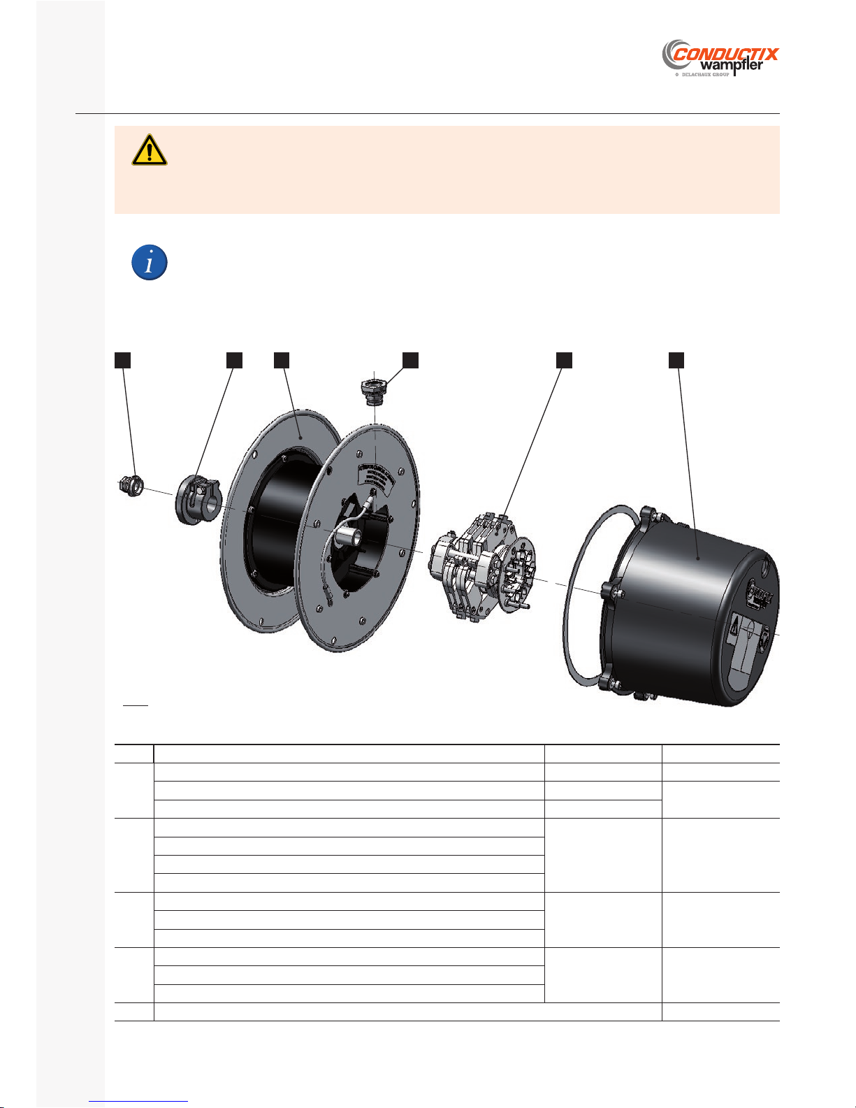
Model SR10J.4.1
D CB
E
A E
Fig.26
P. 35/40
E-360N050-0817
SR10 | SR20 | SR30
Installation, Operating and Maintenance Instructions Manual
Spare partsJ.4
1)
Specify winding direction (unless otherwise stated: winding direction 1)
2)
Specify the type and the serial no. of the slip ring assembly (see § C.3.2.)
In all correspondence, please specify the references of the reel (see § C . 3 . 1. )
Item Description of the kit Order No.
See
A
Mounting fl ange SR10 Consult us § D.3.
Adapter fl ange SR10 AB15 3194944
§ D.8.3.
Adapter fl ange SR10 AB00 - AB18 - AB26 3179107
B
Cable drum SR10 with spring motor 1SA
1)
3172040
§ D.4.
§ D.5.
Cable drum SR10 with spring motor 2SA
1)
Cable drum SR10 with spring motor 2PA
1)
Cable drum SR10 with spring motor 1SL
1)
C
Plastic slip ring housing Ø220 - L1 = 129
Consult us § D.7.Plastic slip ring housing Ø220 - L1 = 159
Plastic slip ring housing Ø220 - L1 = 209
D
Slip ring assembly USR
2)
Consult us § D.6.Brush holder
2)
Complete ring unit
2)
(w/o brush holder)
E
Cable gland § J.4.4.
Safety risk due to poor spare parts!
Incorrect or faulty spare parts can cause damage, malfunctions or total failure of the equipment, as well as affecting safety.
Therefore:
Use only original manufacturer’s spare parts! Screws, nuts and washers must be replaced by fastenings of quality class and dimensions equivalent to the original. -
WARNING
Page 36
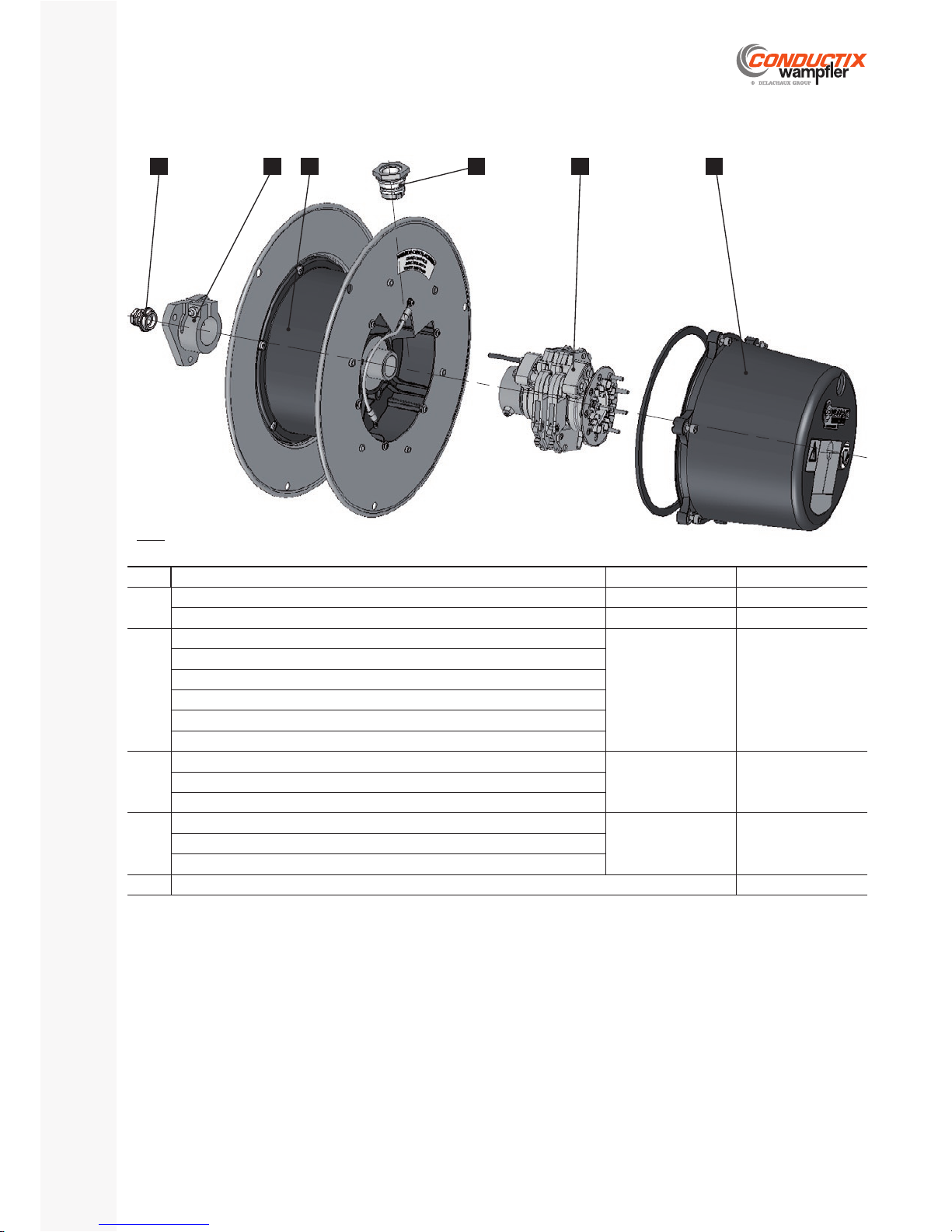
Model SR20J.4.2
SR10 | SR20 | SR30
Installation, Operating and Maintenance Instructions Manual
P. 36/40
E-360N050-0817
E D CBA E
Fig.27
1)
Specify winding direction (unless otherwise stated: winding direction 1)
2)
Specify the type and the serial no. of the slip ring assembly (see § C.3.2.)
Item Designation of the kit Order No.
See
A
Mounting fl ange SR20 Consult us § D.3.
Adapter fl ange SR20 AB01 - AB02 - AB03 - AB04 - AB18 - AB22 - AB26 3171897 § D.8.3.
B
Cable drum SR20 with spring motor 1SA
1)
3172082
§ D.4.
§ D.5.
Cable drum SR20 with spring motor 2SA
1)
Cable drum SR20 with spring motor 2PA
1)
Cable drum SR20 with spring motor 1SR
1)
Cable drum SR20 with spring motor 2SR
1)
Cable drum SR20 with spring motor 2PR
1)
C
Plastic slip ring housing Ø220 - L1 = 129
Consult us § D.7.Plastic slip ring housing Ø220 - L1 = 159
Plastic slip ring housing Ø220 - L1 = 209
D
Slip ring assembly USR
2)
Consult us § D.6.Brush holder
2)
Complete ring unit
2)
(w/o brush holder)
E
Cable gland § J.4.4.
Page 37
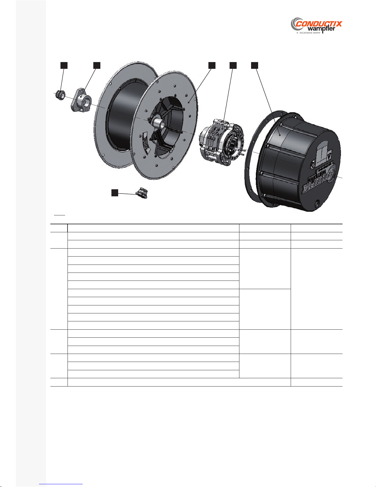
D CBE A
E
Model SR30J.4.3
P. 37/40
E-360N050-0817
SR10 | SR20 | SR30
Installation, Operating and Maintenance Instructions Manual
Fig.28
1)
Specify winding direction (unless otherwise stated: winding direction 1)
2)
Specify the type and the serial no. of the slip ring assembly (see § C.3.2.)
Item Designation of the kit Order No.
See
A
Mounting fl ange SR30 Consult us § D.3.
Adapter fl ange SR30 AB01 - AB02 - AB03 - AB04 - AB18 - AB22 - AB26 3171897 § D.8.3.
B
Cable drum SR30 with spring motor 1SA
1)
317208 4
§ D.4.
§ D.5.
Cable drum SR30 with spring motor 2SA
1)
Cable drum SR30 with spring motor 3SA
1)
Cable drum SR30 with spring motor 2PA
1)
Cable drum SR30 with spring motor 3PA
1)
Cable drum SR30 with spring motor 1SR
1)
317208 6
Cable drum SR30 with spring motor 2SR
1)
Cable drum SR30 with spring motor 3SR
1)
Cable drum SR30 with spring motor 2PR
1)
Cable drum SR30 with spring motor 3PR
1)
C
Plastic slip ring housing Ø330 - L1 = 159
Consult us § D.7.Plastic slip ring housing Ø330 - L1 = 209
Plastic slip ring housing Ø330 - L1 = 314
D
Slip ring assembly USR
2)
Consult us § D.6.Brush holder
2)
Complete ring unit
2)
(w/o brush holder)
E
Cable gland § J.4.4.
Page 38
SR10 | SR20 | SR30
Installation, Operating and Maintenance Instructions Manual
P. 38/40
E-360N050-0817
Dismantling and disposalK
SafetyK.1
Danger of injury due to improper disassembly!
Poor dismantling may result in serious personal injury and material damage.
Therefore:
Before starting the work, clear suffi cient space for assembly. Maintain order and cleanliness in the work area! Loosely stacked or scattered components and tools are a source of accidents.
Dismount components properly. Note the high weight of some components. If necessary, use lifting gear. Handle open, sharp-edges components carefully. Secure components so that they cannot fall or fall over. Involve the manufacturer in case of any unclear points. -
WARNING
Cable glandsK.1.1
Model Order No. SR10 SR20 SR30 cable OD
Cable gland ISO16 N05 N, nickel-plated brass
FR-3092069
8 up to 9,5
Cable gland ISO20 N06 N, nickel-plated brass
FR-3092047
8.5 up to 13
Cable gland ISO25 N07 N, nickel-plated brass
FR-3092048
12 up to 17
Cable gland ISO32 N08 N, nickel-plated brass
FR-3092049
15 up to 22
Cable gland ISO40 N09 N, nickel-plated brass
FR-3092061
19.5 up to 28
Flat fi ber gasket for ISO16
FR-221645-000
Flat fi ber gasket for ISO20
FR-0404035
Flat fi ber gasket for ISO25
FR-0404036
Flat fi ber gasket for ISO32
FR-0404041
Flat fi ber gasket for ISO40
FR-0404042
Danger of death due to suspended loads!
During loading / unloading operations, there is a danger of death from falling parts or those swinging out of control.
Therefore:
Never step under suspended loads. Follow the specifi cations for the lifting points provided. Use only authorized lifting appliances and separate lifting accessories with suffi cient load capacity. Do not use torn or worn ropes, textile slings or straps. Do not attach ropes or straps to sharp corners and edges, and do not knot or twist them. Only move loads under supervision. Set down the load when leaving the workplace. -
WARNING
Risk of falls!
The spring cable reel is mostly composed of rotating moving parts. The reel and its bracket are not designed to withstand
mechanical loads other than those identifi ed during normal operation of the installation.
Therefore:
Do not climb or walk on the reel. -
WARNING
Page 39
P. 39/40
E-360N050-0817
SR10 | SR20 | SR30
Installation, Operating and Maintenance Instructions Manual
DismantlingK.2
After the system is no longer in use, the device must be disassembled and environmentally friendly disposal carried out.
Before starting disassembly:
Remove operating and auxiliary materials as well as residual processing material, and dispose of them in an environmentally appropriate manner.
Then clean the assemblies and components properly and disassemble them as required by applicable local workplace safety and environ- mental protection regulations.
DisposalK.3
Properly disassembled components are to be recycled if no return or disposal agreement has been made.
Scrap metals. Take plastic elements for recycling. The other components are to be disposed of according to their material composition. -
Local community offi cials or special disposal companies can provide information about environmentally appropriate disposal.
Environmental damage due to improper disposal!
Electrical waste, electronic components, lubricants, and other auxiliary materials are subject to hazardous waste disposal
regulations and may only be disposed of by authorized specialists.
CAUTION
Danger of sectioning and severe cuts!
Springs are dangerous elements. When disassembling, take all necessary precautions to avoid sudden release and unfolding
of the springs.
WARNING
S.A.S. CONDUCTIX-WAMPFLER
30 avenue Brillât Savarin | BP39 | 01300 Belley | France
phone +33 (0)4 79 42 50 00 | fax +33 (0)4 79 42 50 05 | internet : www.conductix.com
Page 40
Declaration of incorporationL
 Loading...