

Page 1

For Europe
This drive is in conformity with the EMC directive.
Federal Communications Commission (FCC) Statement
This equipment has been tested and found to comply with the limits for a Class B digital device,
pursuant to part 15 of the FCC Rules.
Those limits are designed to provide reasonable protection against harmful interference in a
residential installation. This equipment generates, uses and can radiate radio frequency
energy and, if not installed and used in accordance with the instructions, may cause harmful
interference to radio communications. However, there is no guarantee that interference will not
occur in a particular installation. If this equipment does cause harmful interference to radio or
television reception, which can be determined by turning the equipment off and on, the user is
encouraged to try to correct the interference by one or more of the following measures:
Reorient or relocate the receiving antennas.
Increase the separation between the equipment and receiver.
Connect the equipment into an outlet on a circlet different from that to which the receiver is
connected.
Warning:
A shielded-type power cord is required in order to meet FCC emission limits and also to
prevent interference to the nearby radio and television reception. It is essential that only the
supplied power cord be used.
Use only shielded cables to connect I/O devices to this equipment.
You are cautioned that changes or modifications not expressly approved by the party
responsible for compliance could void your authority to operate the equipment.
1
Page 2

TABLE OF CONTENTS
1. INTRODUCTION.........................................................................4
1.1 K
EY FEATURES
.............................................................................................4
2. PRODUCT OVERVIEW ..............................................................5
2.1 M
ODE OPERATION
.........................................................................................5
2.1.1 Self-Diagnostic Mode .............................................................................5
2.1.2 2.1.2 Configuration Mode .......................................................................6
2.1.3 Operation Mode ......................................................................................7
2.2
Condre A/V RAID F
EATURES
....................................................................10
2.2.1 Array Management ...............................................................................10
2.2.2 RAID Levels..........................................................................................10
2.2.3 Hot Swap Disk Cartridges ....................................................................15
2.2.4 Automatic Global Hot Spare.................................................................15
2.2.5 Automatic Drive Rebuild.......................................................................16
2.2.6 PAGE and FAX Notification ..................................................................16
3 HARDWARE INSTALLATION...................................................17
3.1 B
EFORE STARTING
.......................................................................................17
3.2 T
HE CONTROLLER BOX
...............................................................................17
3.3 T
HE CONTROL PANEL
..................................................................................18
3.3.1 Control Panel Key Definitions...............................................................18
3.4 M
EMORY MODULE
.......................................................................................19
3.4.1 Installing a SO DIMM Module...............................................................20
4 CONFIGURING Condre A/V RAID...........................................21
4.1 I
NITIAL
RAID C
ONFIGURATION
.....................................................................21
4.1.1 Quick Setup ..........................................................................................21
4.1.2 Single Host Configuration.....................................................................21
4.1.3 Single Host Configuration for Logical Units..........................................23
4.1.4 EXAMPLE for Logical units of Single Host Configuration ....................25
4.1.5 Dual Host Configuration .......................................................................27
4.1.6 EXAMPLE for Dual Host Configuration ................................................30
4.1.7 Dual Host Configuration for Redundant Server & HA software .........31
4.1.8 Example for Redundant Server and HA software Configuration:.........32
4.2 E
XPAND THE
RAID
CAPACITY
.......................................................................33
4.3 T
HE
Condre A/V RAID C
ONFIGURATION MENU
...........................................34
4.3.1 Quick Setup menu ................................................................................34
4.3.2 RAID Params menu..............................................................................35
2
4.3.3 SCSI Params menu..............................................................................37
Page 3

4.3.4
RS232 Params menu ...........................................................................40
4.3.5 System Params menu ..........................................................................41
4.3.6 NVRAM menu.......................................................................................43
4.3.7 RAID Funcs menu ................................................................................44
5 PAGE AND FAX NOTIFICATION..............................................47
5.1 M
ODEM PORT SETTINGS
.............................................................................47
5.1.1 Modem Access .....................................................................................47
5.2 C
ONFIGURING
PAGE
AND
FAX N
OTIFICATION
..............................................47
5.2.1 Paging Notification................................................................................48
4.3.1 FAX Notification....................................................................................49
6 MONITOR UTILITY ...................................................................50
6.1 K
EY DEFINITIONS UNDER
ANSI T
ERMINAL
....................................................50
6.2 C
ONNECTING TERMINALS
............................................................................50
6.2.1 Communication Ports Settings .............................................................51
6.2.2 Terminal Access ...................................................................................51
6.2.3 Using a PC for Terminal Emulation ......................................................51
6.3 U
SING THE MONITOR UTILITY
.......................................................................52
6.3.1 Running Configuration Mode................................................................53
6.3.2 Updating the Firmware .........................................................................53
7 TROUBLESHOOTING ..............................................................54
APPENDIX A - ERROR MESSAGES ..............................................57
APPENDIX B : TECHNICAL SPECIFICATIONS .............................60
APPENDIX C : SCSI CABLE SPECIFICATIONS............................61
APPENDIX E : GLOSSARY.............................................................62
APPENDIX F : RECORD THE Condre A/V RAID SETTING ..........64
3
Page 4

1. Introduction
Congratulations on your purchase of the
Condre A/V RAID--
a cost effective, high performance RAID solution.
The Condre A/V RAID is designed to meet today demand of higher storage solutions for the
emerging needs of databases, e-mail, web servers and imaging systems providing,
maximum data protection and exceptional performance in a storage controller. Target
usage ranges from small business to departmental and corporate server needs. The
Condre A/V RAID is designed for easy integration, smooth data expansion and server
migration.
1.1 Key Features
The Condre A/V RAID supports the following features:
•
Support for RAID Levels 0, 1, 0+1, 3and 5
•
Host System independent
•
Operating System independent
•
Intel i80303 64-bit RISC High performance processor
•
Support Dual Ultra160 SCSI channel
•
Support 12 ~ 16 ATA-100/133 IDE channel
•
Superior Accusys Array Management Firmware
•
Flexible cache size of up to 512MB
•
Support up to 16 logical units
•
Support on-line capacity expansion.
•
Automatic Hot Swap, Hot Spare and Drive Rebuild Support
•
Disk fail LED Indication
•
Bad Sector reassignment
•
Programmable Page and FAX event notification
•
Remote monitoring through terminal
•
UPS support through a standard UPS interface
4
Page 5

2. Product Overview
The Condre RAID is a full feature RAID designed to provide the utmost in fault
tolerance, redundancy, reliability and performance. The following sections describe the
features in the Condre RAID.
2.1 Mode Operation
The Condre RAID operates in three modes: Self-Diagnostic Mode, Configuration Mode and
Operation Mode.
2.1.1 Self-Diagnostic Mode
To ensure flawless operation, Condre RAID has a built-in self-diagnostic utility.
Self-diagnostic Mode occurs automatically upon power up, or after the Condre RAID has
been reset. During this mode, all components are tested, and any potential problems
are reported.
The Self-Diagnostic Mode runs three major diagnostic tests. The first diagnostic
includes testing the CPU and supporting core logic chips, the internal bus, memory,
SCSI controller, enhanced IDE controllers, and RS-232 controllers. The second
diagnostic tests for the presence of disks on each individual disk channel. It also checks
the functionality of the disk found. The final diagnostic tests the RAID functionality.
5
Page 6

2.1.2 2.1.2 Configuration Mode
Configuration Mode may be selected whenever the Enter button is pressed during
Operation Mode or when the Monitor Utility is invoked from the remote terminal. In
Configuration Mode the user is able to modify the settings of the Condre RAID and perform
different functions to the controller. It is important to note when running Configuration
Mode the Condre RAID should be off-line and not accessed by any application.
2.1.2.1 Entering a Password
If the password-checking feature is enabled, you will be prompted to enter your password
and will not be allowed to proceed until the password is entered correctly. The default
password is “00000000”. Refer to section
4.3.5 System Parma Menu
for instructions
on changing the default password.
6
You may use the front panel buttons to enter the password. Use the “↑” and “↓” arrow
keys to scroll through the available characters, then use the ”Enter” button to select the
character and move to the next position. Once all the characters have been entered
press the ”Enter” button to access the Configuration Mode.
Page 7
2.1.3 Operation Mode
The front panel LCD continuously displays the current status of the Condre RAID. A typical
display looks like the following:
Condre RAID
OOOOOOOOOOOS
Press [ ▼ ]
Installed Memory
MB
Press [ ▼ ]
RAID Capacity
GBytes
Press [ ▼ ]
RAID Capacity
GBytes
Press [ ▼ ]
Firmware Version
Press [ ▼ ]
Serial Number
Press [ ▼ ]
CPU Type
I960
7
Press [ ▼ ]
Page 8
RAID Member
Press [ ▼ ]
Disk 1
Press [
▼ ]
Disk 16
Press [ ▼
]
RAID Level
R5
Press [ ▼ ]
SCSI ID
Press [ ▼ ]
SCSI LUN
8
Page 9
Field Description
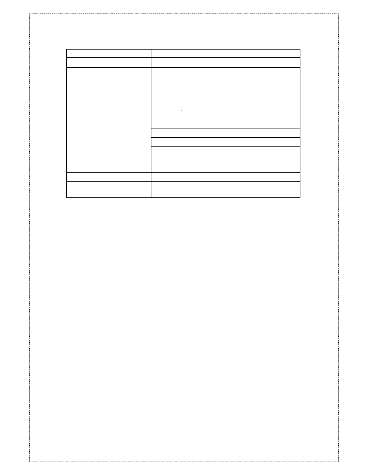
Condre A/V RAID The Condre RAID model number.
OOOOOOOOOOOS
The 12 ~ 16 disks channel status. The first
left O is channel 1. You can press [▼]
button to view the next page.
Other symbols are:
Symbol Description
x Disk is not installed
A Disk is being Added
O Disk is On-line
S Disk is a Spare disk
R Disk is Removed
I Disk is been checking
R5
The RAID level (0, 1,0+1,3, 5) configuration.
ID:0
The SCSI ID (0 - 15) configuration.
Alternating cursor indicating operational
status.
When the Enter button is pressed in operation mode, the Condre RAID will enter to
Configuration Mode.
Note: During Configuration Mode if no button is pressed for 3 minutes (180 seconds),
the Condre RAID will automatically switch back to Operation Mode.
9
Page 10
2.2 Condre RAID Features
The Condre RAID supports RAID Levels 0, 1, (0+1), (3) and 5, automatic failed-drive
detection, transparent drive rebuilds, bad sector re-mapping, automatic hot spare and
on-line hot swap.
2.2.1 Array Management
The unique Condre RAID array management firmware utilizes multitasking real-time kernel
technology to manage the controller. Additional features are real-time I/O load analysis,
on-line diagnostics, event logging and broadcasting, and device inventory management.
These features can be accessed locally or via modem to allow centralized monitoring
and control of the Condre RAID.
2.2.2 RAID Levels
What are RAID levels?
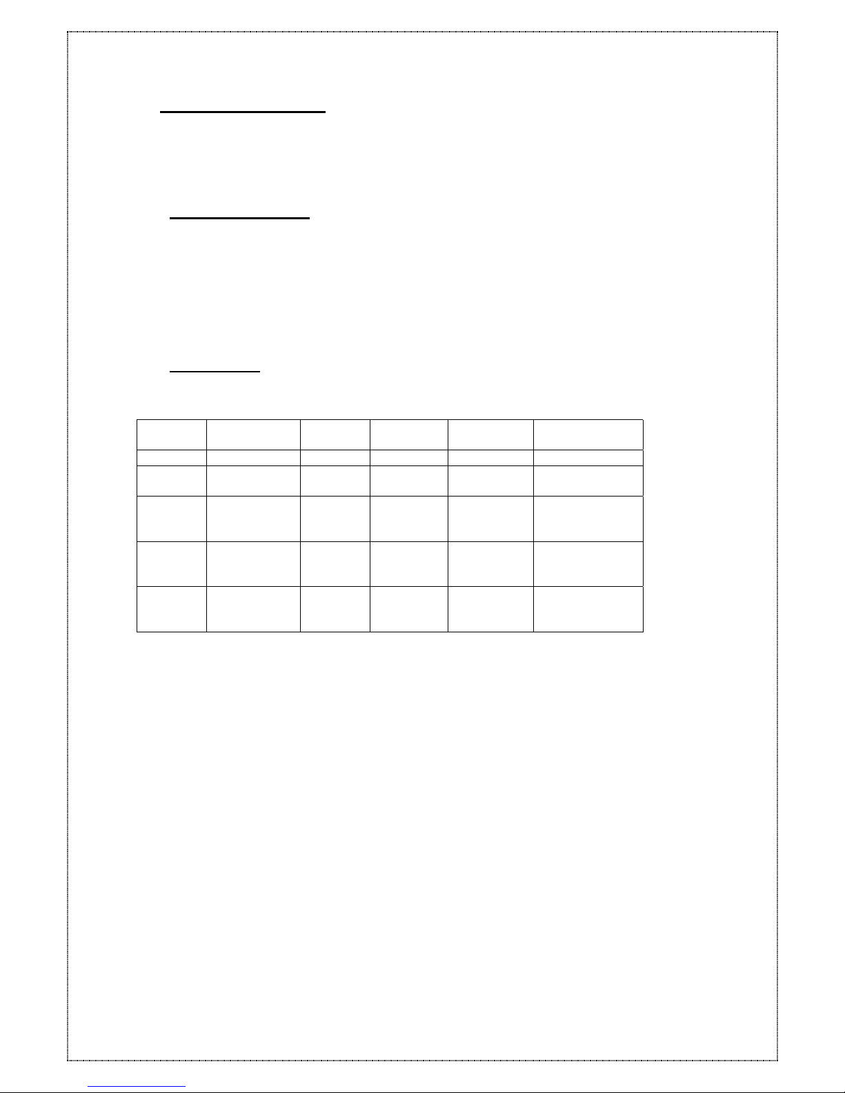
RAID
Level
Description
Minimum
Drives
Data
Availability
Performance
Sequential
Performance
Random
None RAID Non-RAID 1 Drive Drive
RAID 0 Disk Striping N = NRAID R: Highest
W: Highest
R: High
W: Highest
RAID 1
(0+1)
Mirroring Plus
Striping
(if N>1)
N+1 >NRAID
= RAID 5
R: High
W: Medium
R: Medium
W: Low
RAID 3 Striping with
Parity on
dedicated disk
N+1 >NARID
= RAID 5
R: High
W: Medium
R: Medium
W: Low
RAID 5 Striping with
Interspersed
parity
N+1 >NRAID
= RAID 5
R: High
W: Medium
R: High
W: Low
10
The Condre RAID supports RAID Levels 0, 1, (0+1), (3) and 5. Depending on the
application that will be used each RAID level offers a difference in performance,
functionality and fault tolerance. The following is a brief explanation of each RAID level.
Before configuring the Condre RAID be sure to know what RAID level is best suited for
your application.
Page 11
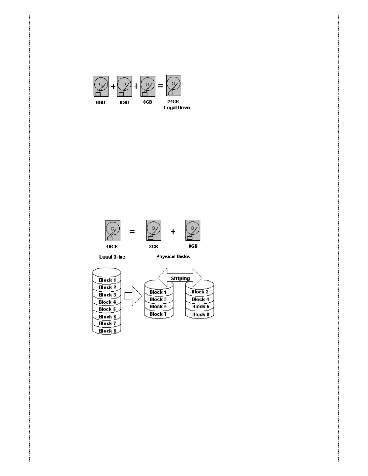
2.2.2.1 Disk Spanning (None RAID)
None RAID
Minimum Disks required 1
Capacity N
Redundancy No
None RAID stands for Non-RAID. The capacity of all the drives is combined to become
one logical drive (no block striping). In other words, the capacity of the logical drive is
the total capacity of the physical drives. NRAID does not provide data redundancy.
2.2.2.2 Disk Striping (RAID 0 )
RAID 0
Minimum Disks required 2
Capacity N
Redundancy No
Striping refers to the storing of data across multiple drives in a drive group. If there are
three drives in a drive group then the subsequent data will be stored across all three
drives. This creates a very high performance virtual disk with the capacity equal to the
combined capacity of the installed disks.
RAID Level 0 provides high data reliability and availability and very high performances
11
Page 12
for both read and write operations. No redundant parity is generated for protection
against disk failure.
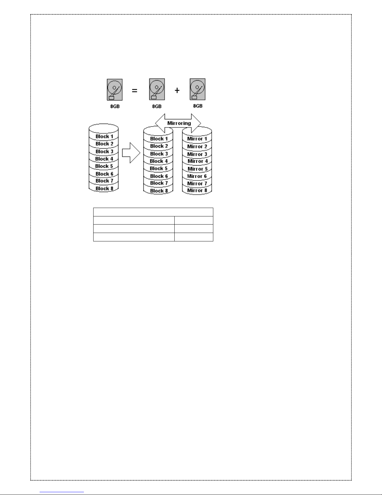
2.2.2.3 Mirroring ( RAID 1 )
RAID 1
Disks required 2
Capacity N/2
Redundancy Yes
RAID 1 mirrors the data stored in one hard drive to another. RAID 1 can only be
performed with two hard drives. If there are more than two hard drives, RAID (0+1) will
be performed automatically.
Mirroring refers to the replication of data on two or more drives. Each drive contains a
mirror image of the data on the other drive. Virtual disk space equals to half of the
combined capacity of the installed disks although mirroring causes operational
overhead resulting in lower performance for write operations it does provide the highest
data reliability among RAID Level 0 to 5 with very high performance for read intensive
operations.
12
Page 13
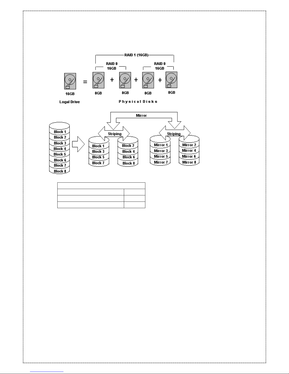
2.2.2.4 Striping with Mirroring (RAID 0+1)
RAID (0+1)
Minimum Disks required 4
Capacity N/2
Redundancy Yes
RAID (0+1) combines RAID 0 and RAID 1-Mirroring and Striping. RAID (0+1) allows
multiple drive failure because of the full redundancy of the hard drives. If there are more
than two hard drives assigned to perform RAID 1, RAID (0+1) will be performed
automatically.
13
Page 14
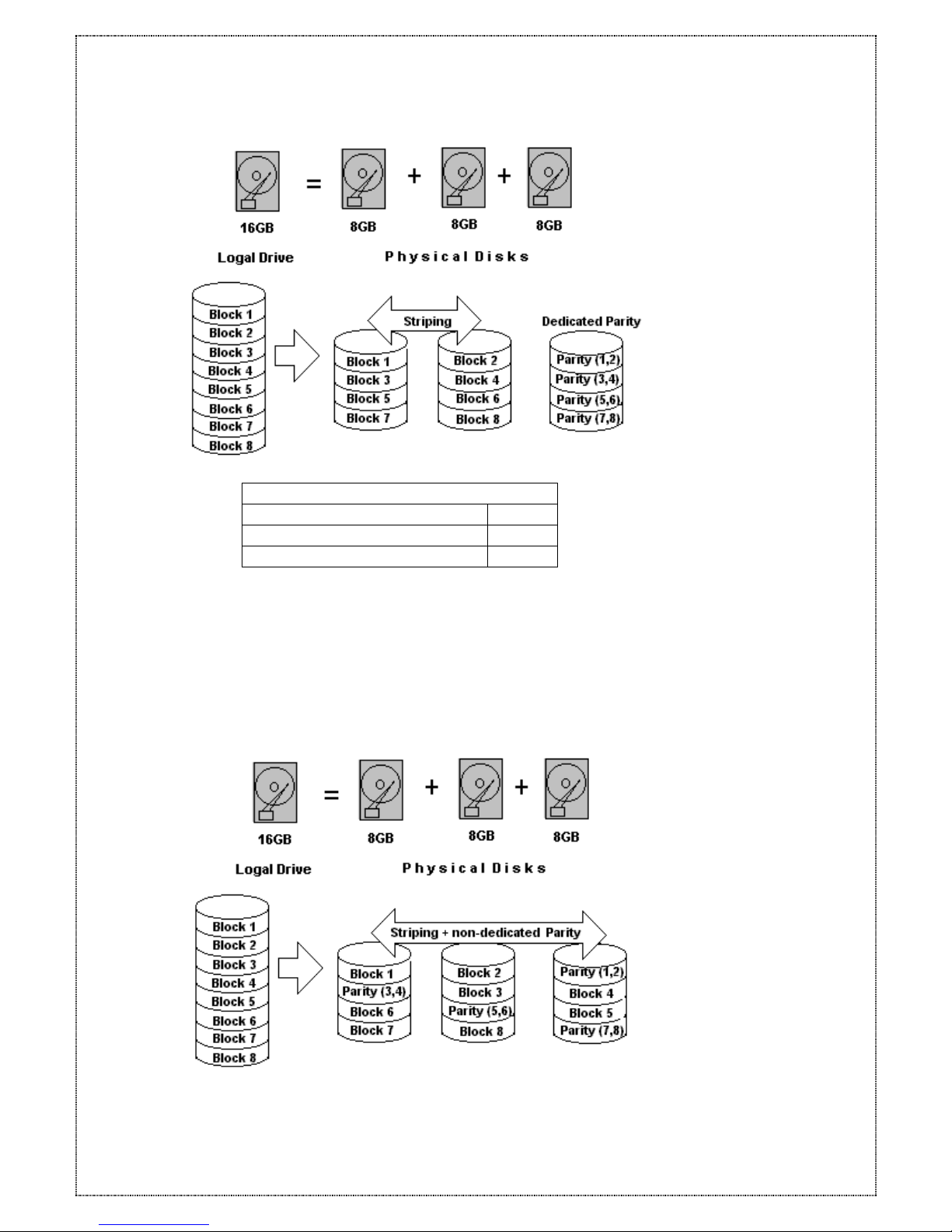
2.2.2.5 Striping with Dedicated Parity Disk (RAID 3)
RAID 3
Minimum Disks required 3
Capacity N-1
Redundancy Yes
RAID 3 performs Block Striping with Dedicated Parity. One drive member is dedicated
to storing the parity data. When a drive member fails, the controller can
recover/regenerates the lost data of failed drive from the dedicated parity drive.
2.2.2.6 Striping with non-Dedicated Parity (RAID 5)
14
Page 15
RAID 5
Minimum Disks required 3
Capacity N-1
Redundancy Yes
Striping with Parity is a method of storing data striped across multiple drives like RAID 0
but with parity (redundant data calculated by XOR logic used to reproduce data that is
lost) also striped across the drives. RAID Level 5 offers very high data redundancy,
availability and performance.
2.2.3 Hot Swap Disk Cartridges
Hot Swapping allows for the removal and installation of disk drives without interruption of
data access while the Condre RAID system is in use. Automatic Hot Spare allows the
removal and replacement of a faulty drive without power down the system. This is usually
performed when there is no Hot Spare drive configured. There is no need to power down
the system.
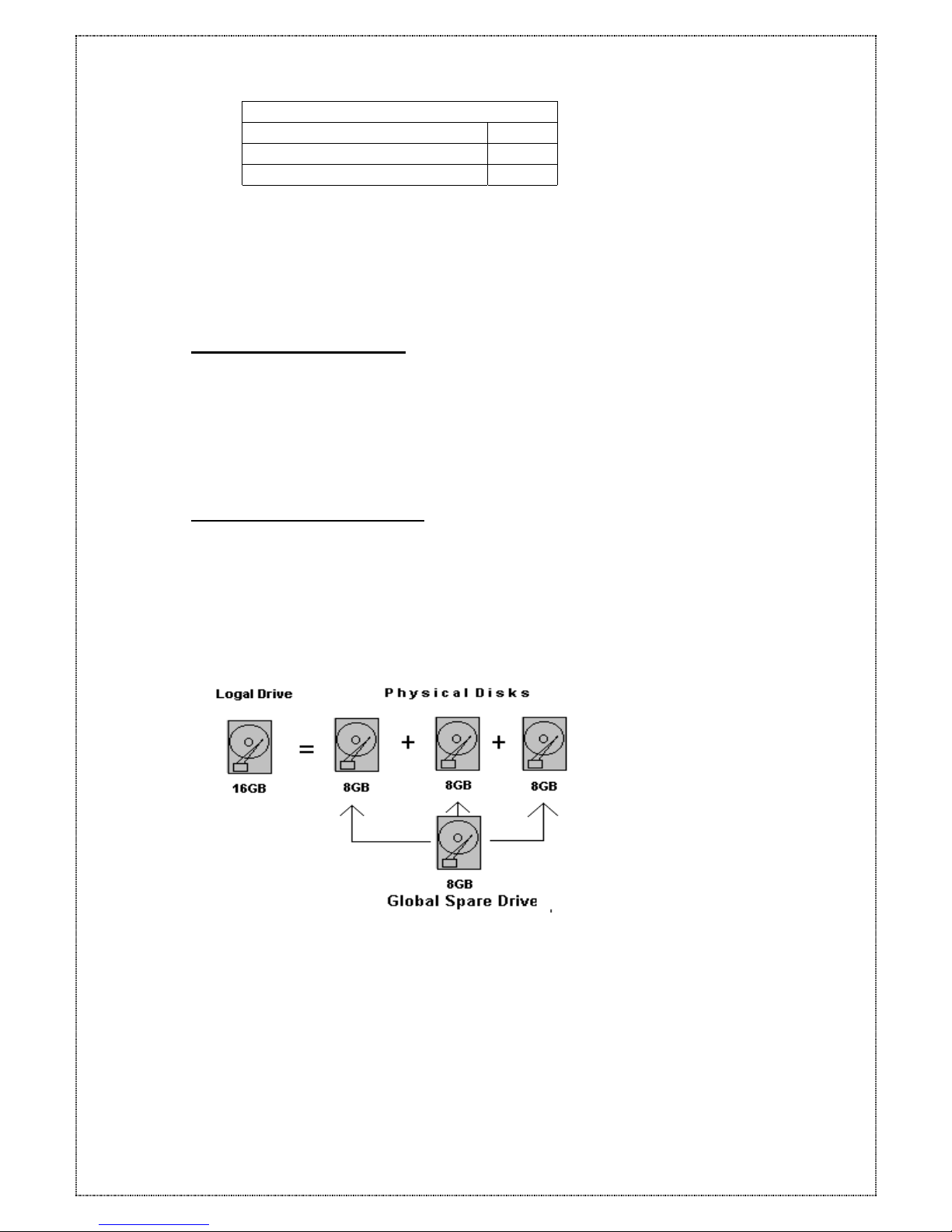
2.2.4 Automatic Global Hot Spare
Hot Spare allows for the automatic replacement of a failed drive without requiring
intervention. When a disk fails the Condre RAID will automatically replace the faulty drive
with the configured hot spare disk, thus allowing removal and replacement of a faulty
drive without having to power down the system.
Global Spare Drive
Global Spare Drive does not only serve one specified logical drive. When a member
drive from any of the logical drive fails, the Global Spare Drive will join that logical drive
and automatically starts to rebuild.
15
Page 16
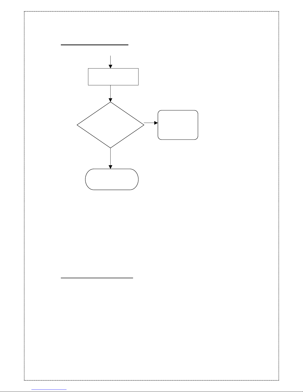
2.2.5 Automatic Drive Rebuild
Automatic Rebuild
Yes
No
When a member drive in the logical drive failed, the controller will first check whether
there is a Local Spare Drive assigned to this logical drive. If yes, it will automatically
start to rebuild.
If there is no Local Spare Drive available, the controller will search for a Global Spare
Drive. If there is a Global Spare Drive, it will automatically rebuild the logical drive.
If neither Local Spare Drive nor Global Spare Drive is available, the controller will not
try to rebuild unless the user applies a forced-manual rebuild.
2.2.6 PAGE and FAX Notification
The Condre RAID does not require additional software for system monitoring and analysis.
The Condre RAID array management firmware continuously monitors the system activity
and immediately launches the Page and FAX event notification feature if any failure
occurs. Up to two pagers and two fax-stations can be notified instantaneously and
repeatedly for extra insurance.
16
Wait for new drive t
o
automatic rebuild
Automatic
Rebuild using
the Global
Spare Drive
One member drive
fails in logical drive
Any Global
Spare Drive
assigned to
this lo
g
ical
Page 17
3 Hardware installation
3.1 Before starting
The ProRAID functions as a normal SCSI disk drive to your system. Please ensure your
computer system has embedded SCSI support or a SCSI host adapter is already
installed. A device driver for supporting the embedded SCSI or SCSI adapter must be
properly loaded and configured. Please follow your system or SCSI host adapter
manual for the preparation.
If you are an advanced user or are familiar with the installation requirements for a RAID
subsystem you may skip ahead to section 4. Configuring Condre RAID
3.2 The Controller Box
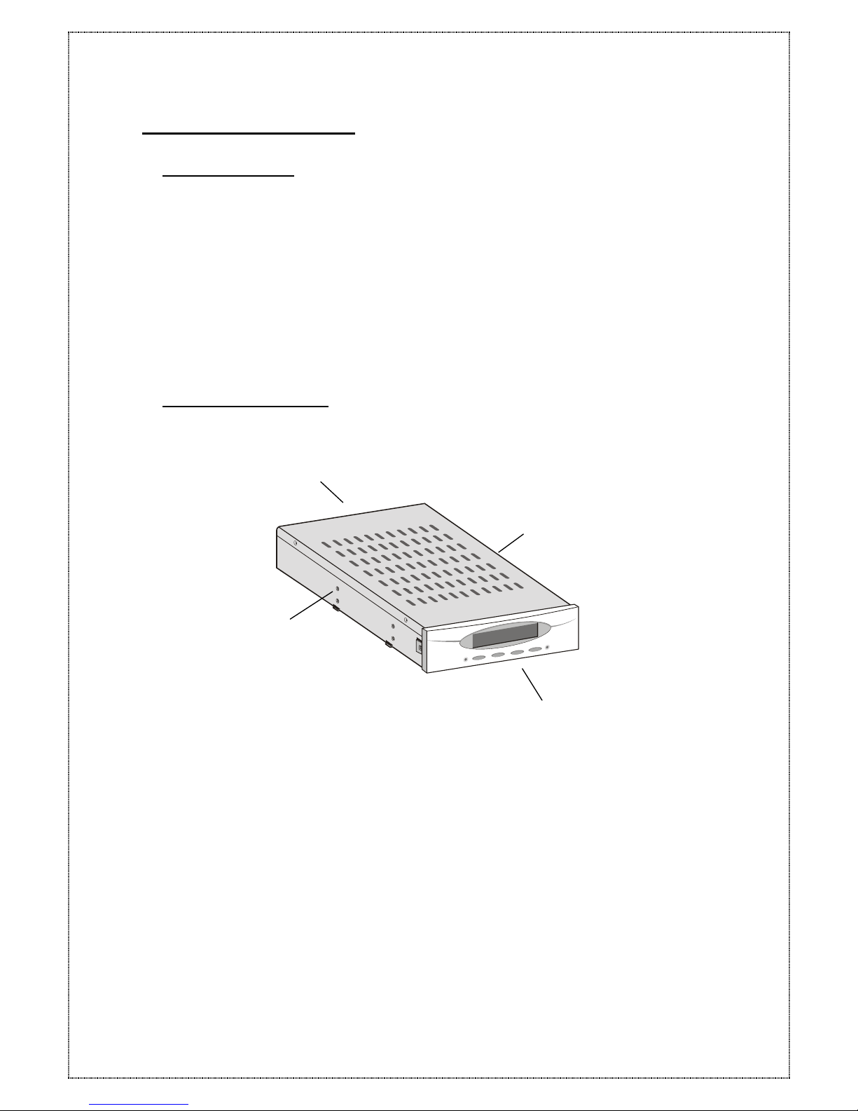
The controller box includes RAID controller board, Control panel interface, box cover, holes for
mounting screws and rear connector board. Please see the below pictures.
Front/Interface
Cover
Holes for Mounting Screws
Rear/Connectors
17
Page 18
3.3 The Control Panel
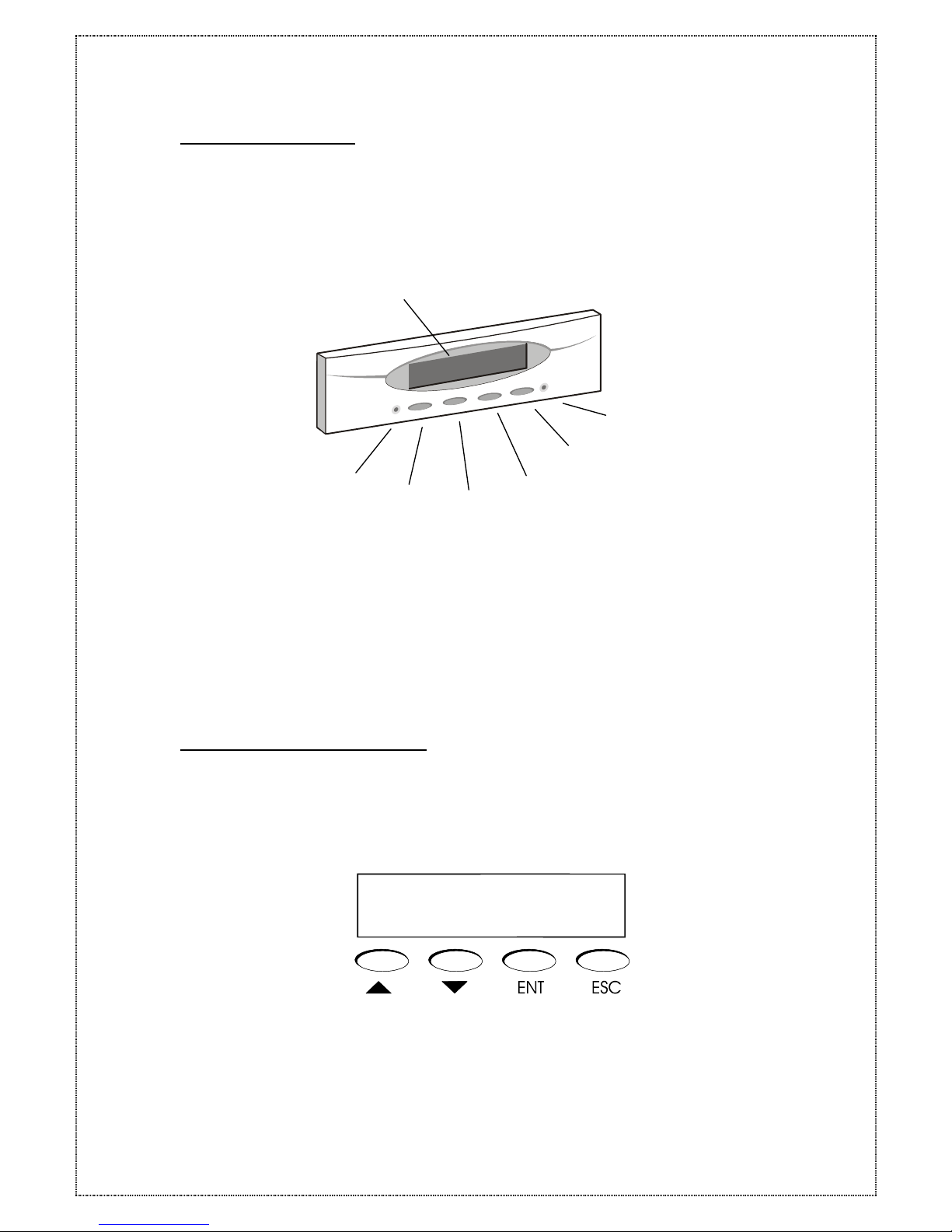
The Condre RAID Control Panel consists of a two line by the 16 character LCD display, 4
push button switches and 6 LEDs. It provides a way to configure and monitor the
operation of the Condre RAID.
Condre RAID Control Panel
Activity LED, indicates data is being accessed
Scroll Up button
Scroll Down button
Select button (ENT), to choose or exercise an option
Escape button (ESC), to return to the previous menu
or cancel a selection
Power LED,
LCD, displays messages for configuration
3.3.1 Control Panel Key Definitions
A menu of configuration options will appear on the display. By using the Up Arrow,
Down Arrow, ESC, and Enter buttons, you can traverse the various menu levels and
configure the desired parameters. These buttons perform the following functions:
18
Page 19
(▲) Up Arrow : use to scroll upward through the menu items
(▼) Down Arrow : use to scroll downward through the menu items
ENT: use to select a menu item, open a sub-menu, and also use to select a value.
ESC: use to exit a sub-menu and return to the previous menu
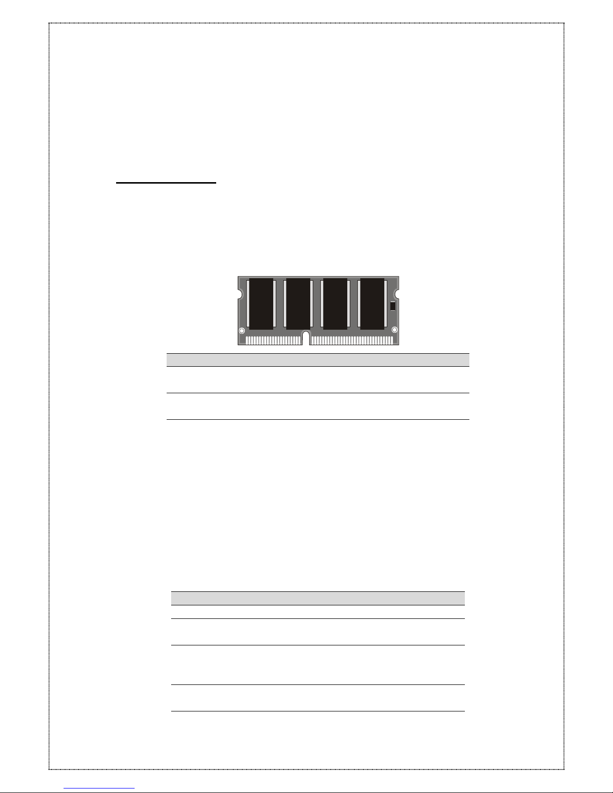
3.4 Memory Module
The Condre RAID controller requires a minimum of 32 MB DRAM SO DIMM (Small Outline, Dual
Inline Memory Modules) installed in the socket on the controller board in order to operate. The
controller box is normally delivered without any DRAM installed.
SO-DIMM Specification
Minimum Recommended
144-pin SDRAM SO DIMM
modules (PC-100, 60~80 ns).
SDRAM
SO DIMM module, with or
without parity.
With parity, for security
Minimum of one SO DIMM
with 32 MB. The memory card
socket can support 32, 64,
128, 256 or 512 MB of
memory.
Minimum of 32 MB, more
memory (Up to 512MB)
equals better
performance.
The size of the memory
module defines the cache
writing space available to
the Condre RAID.
NOTE: The Condre RAID controller can only accept certain types of SO DIMM memory modules.
Check the table below to find supported modules.
19
SDRAM Architecture
512 MB
16 (32M x 8)
256 MB
16 (16M x 8), 8 (32M x 8)
or 8 (16M x 16)
128 MB
16 (8M x 8), 8 (16M x8), 8
(8M x16) or
4 (16M x 16)
64 MB 8 (8M x 8), 8 (4M x 16) or
4 (8M x 16)
32 MB 4 (4M x 16)
Page 20
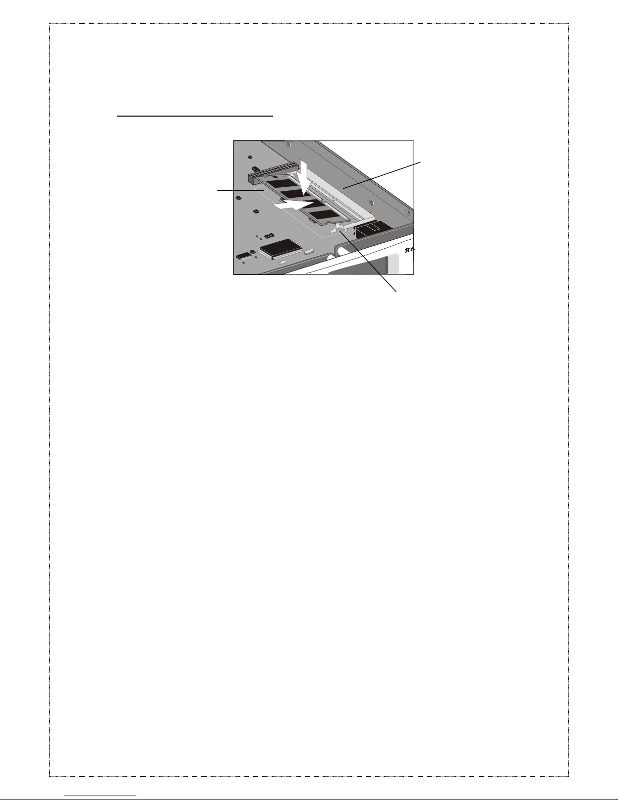
3.4.1 Installing a SO DIMM Module
Please follow the below procedures to install SO-DIMM module.
1. Power off the system and disconnect the power connector.
2. Locate the SO DIMM socket on the controller board.
3. To install a memory card, hold the memory card with the edge connector side
towards the slot. The edge connector is divided into two unequal lengths. With the
controller box facing you, the shortest edge is closest to the front of the box, the
longest end is nearest the back.
4. Hold the card at a shallow angle (about 25 degrees) and insert the edge connector
into the connector slot. The “gold teeth” of the edge connector should no longer be
visible when the card is fully inserted.
5. Press the module downwards so that it is flat inside the compartment. You can hear
an audible click as the latches of the connector lock the card in place.
20
To remove a module that is already in place, unhook the latches on either side of the
module. Put the card in vertical position., and lift it out of the socket.
Page 21

4 Configuring Condre RAID
The following sections describe how to configure the Condre RAID for operation. To
configure the Condre RAID you must configure the RAID settings and the SCSI settings.
After these two steps are completed the Condre RAID will seem like a normal SCSI hard
disk to the host system.
4.1 Initial RAID Configuration
This section provides instructions on how to setup a RAID configuration for the first time.
The instructions use the front control panel, however these steps may also be
performed using a remote terminal or terminal emulation program. Refer to section 6
Monitor Utility for instructions on configuring and using the RS-232 port and monitor
utility.
For Go to section
Quick Setup 4.1.1
Single Host 4.2.1
Dual Host 4.2.4
4.1.1 Quick Setup
1. Turn on the Condre RAID from power supply switch.
2. Press the [ENT] button to display the “Main Menu” menu.
3. Press the [ENT] button to open the “0 Quick Setup” menu.
4. Press the down arrow [▼] button until the “01 Quick Setup” menu is displayed then
press [ENT] button.
5. Press the down arrow [▼] button until the “011 Reconfim” menu is displayed then
press the [ENT] button.
6. Select “Yes” to change an existing RAID configuration.
4.1.2 Single Host Configuration
1. Turn on the Condre RAID from power supply switch.
2. Press the [ENT] button to display the “Main Menu” menu.
3. Press the [ENT] button to open the “1 RAID Params” menu.
4. Press the down arrow [▼] button until the “11 Re-conf RAID” menu is displayed then
press [ENT] button.
21
5. Press the down arrow [▼] button until the “12 RAID Level” menu is displayed then
Page 22
press the [ENT] button.
6. Select the listing “0, 1,5” to configure for RAID Level then press the [ENT] button.
7. Press the down arrow [▼] button until the “13 Disk Number” menu is displayed then
press the [ENT] button.
8. Use the down arrow [▼] buttons to select the number of disks to configure for the
ACS-8910 then press the [ENT] button.
NOTE: This disk number does not include “hot spare” disk.
9. Press the [ESC] button to return to the “Main Menu” menu.
10. Press the down arrow [▼] button until the “2 SCSI Params” menu is displayed then
press the [ENT] button.
11. Press the down arrow [▼] button until the “21 Set SCSI ID” menu is displayed then
press the [ENT] button.
12. Use the down arrow [▼] button to select a SCSI ID to set the ACS-8910 then press
the [ENT] button.
NOTE: The default setting is SCSI ID 0.
13. Press the down arrow [▼] button until the “22 Termination” menu is displayed then
press the [ENT] button.
14. Use the down arrow [▼] buttons to enable or disable the SCSI termination for the
ACS-8910 then press the [ENT] button.
NOTE: If the Condre RAID is the only SCSI device on the bus or is at the end of a
daisy chain the termination should be enabled. If the Condre RAID is in the middle of a
daisy chain the termination should be disabled.
15. Press the down arrow [▼] button until the “23 Tag Queuing” menu is displayed then
press the [ENT] button.
16. Use the down arrow [▼] buttons to enable or disable the Tag Queuing for the
Condre RAID then press the [ENT] button.
NOTE: The default setting is Tag Queuing is “Enabled”. Tag Queuing allows the
Condre RAID to process multiple requests thus improving performance.
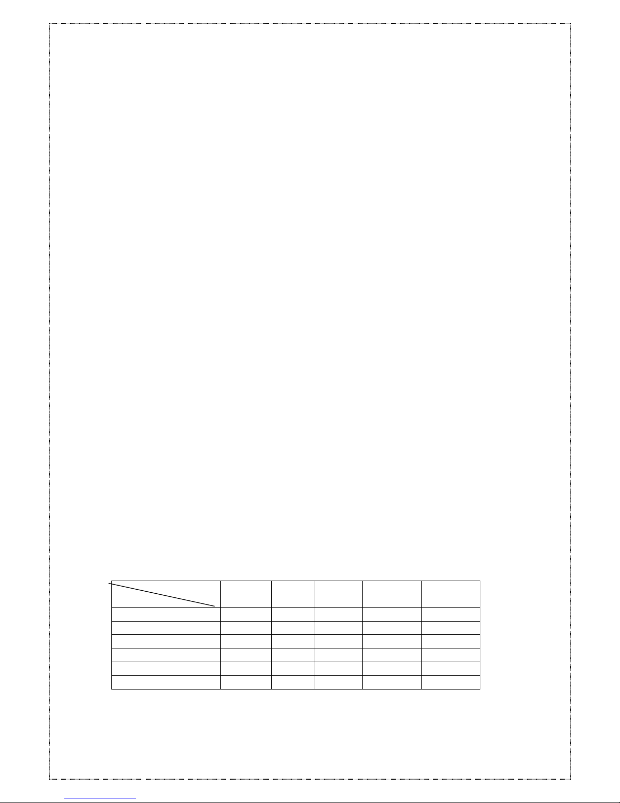
17. Press the down arrow [▼] button to select the “224 Ultra ” and “ 225 Wide” menu.
18. Follow next list to setup SCSI interface of Host.
Speed/Wide Wide Fast Ultra Ultra2 Ultra 3
SCSI Interface
SCSI-2 Disable
[ENT]
Wide SCSI Enable
[ENT]
Ultra SCSI Disable
[ENT]
Ultra Wide SCSI Enable
[ENT]
Ultra 2 SCSI Enable
[ENT]
Ultra 160 SCSI Enable
[ENT]
19. Press the [ESC] button to return to the “Main Menu” menu.
20. Press the down arrow [▼] button until the “5 NVRAM” menu is displayed then press
the [ENT] button.
22
Page 23

21. Press the down arrow [▼] button until the “51 Update NVRAM” menu is displayed
then to press the [ENT] button.
22. Use the down arrow [▼] button until the “Yes” option is displayed then to press the
[ENT] button.
23. Use the down arrow [▼] button until the “53 Restart” menu is displayed then press
the [ENT] button.
24. Use the down arrow [▼] button until the “Yes” option is displayed then press the
[ENT] button. NOTE: This will automatically restart the Condre RAID.
4.1.3 Single Host Configuration for Logical Units
The Condre RAID controller can support up to 8 logical units. A RAID array may
be divided into multiple logical units. A logical unit is that portion of a disk array seen
by the host system as a single logical device. Each logical unit is identified to the host
by its Logical Unit Number.
1. Please finish section Single host configuration steps first.
2. Press the [ENT] button to open the “6 RAID Funcs” menu.
3. Press the down arrow [▼] button until the “62 Init R5/R3” menu is displayed then press
[ENT] button.
4. Use the down arrow [▼] button until the ”STOP” option is displayed then press the
[ENT] button.
5. Press the [ESC] button to return to the “Main Menu” menu.
6. Press the [ENT] button to open the “1 RAID Parmas” menu.
7. Press the down arrow [▼] button until the “14 Slice” menu is displayed then press the
[ENT] button.
NOTE: The Slice will allow you to divide the partition size of Condre RAID.
8. Press the down arrow [▼] button until the “141 Slice0(MB)” menu is displayed then
press [ENT].
9. Key-in the capacity you want in Slice 0 then press [ENT] button.
10. Press the down-arrow [▼] button to select from “142 Slice 1(MB)” to “148
Slice7(MB)” follow steps 8 and 9
11. Press the [ESC] button to return to the “Main Menu” menu.
12. Press the down arrow [▼] button until the “2 SCSI Params” menu is displayed then
press the [ENT] button.
13. Press the down arrow [▼] button until the “216 LUN map” menu is displayed then
press the [ENT] button.
14. Press the down arrow [▼] button until the “2161 LUN 0” menu is displayed then
press the [ENT] button.
23
15. Follow the next table to setup “LUN” menu.
Page 24

LUN 0 Slice 0
LUN 1 Slice 1
LUN 2 Slice 2
LUN 3 Slice 3
LUN 4 Slice 4
LUN 5 Slice 5
LUN 6 Slice 6
LUN 7 Slice 7
NOTE: The LUN numbers depend on how many slice numbers you set.
16. Press the [ESC] button to return to the “Main Menu” menu.
17. Press the down arrow [▼] button until the “5 NVRAM” menu is displayed then press
the [ENT] button.
18. Press the down arrow [↓] button until the “51 Update NVRAM” menu is displayed
then press the [ENT] button.
19. Use the down arrow [▼] button until the “Yes” option is displayed then press the
[ENT] button.
20. Use the down arrow [▼] button until the “53 Restart” menu is displayed then press
the [ENT] button.
21. Use the down arrow [▼] button until the ”Yes” option is displayed then press the
[ENT] button.
22. Press the [ENT] button to open the “6 RAID Funcs” menu.
23. Press the down arrow [▼] button until the sub-menu “62 Init R5/R3” option is
displayed then press [ENT] button.
24. Use the down arrow [▼] button until the ”START” option is displayed then press the
[ENT] button.
24
NOTE: The Condre RAID is now configured completely for logical units.
Page 25
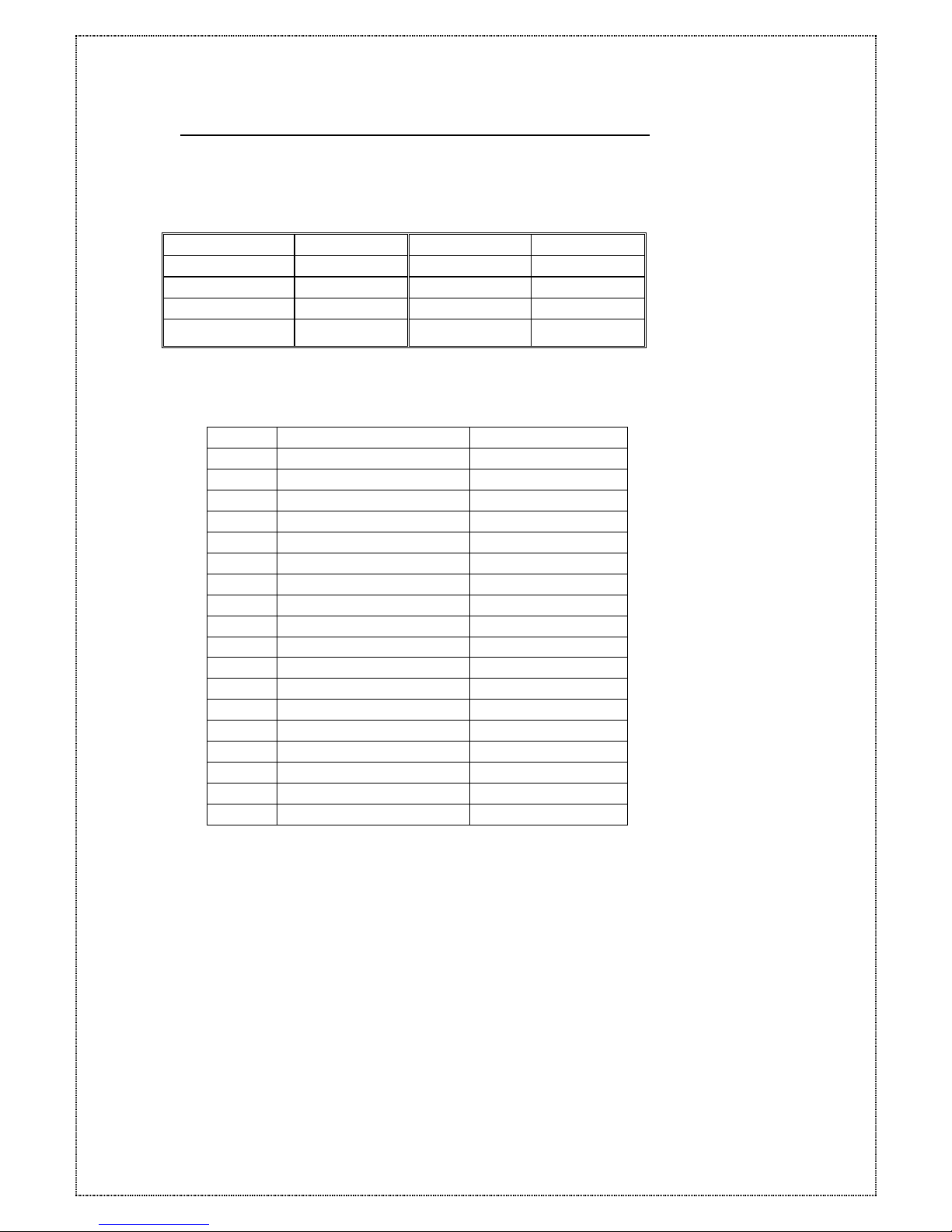
4.1.4 EXAMPLE for Logical units of Single Host Configuration
Example 1 :
Normal Setup for logical units:
Disk 5 GB x 6 Partition 4
On-line Disk 5 Partition 1 5 GB
Spare Disk 1 Partition 2 8 GB
RAID Level 5 Partition 3 7 GB
SCSI ID 3 Partition 4 5 GB
ACS-8910 Configuration:
Step Menu Setting
1 11 Re-conf RAID Yes
2 12 RAID Level 5
3 13 Disk Number 5
4 21 Set SCSI ID 3
5 51 Update NVRAM Yes
6 53 Restart Yes
7 62 Init R5 STOP
8 141 Slice 0 5000 MB
9 142 Slice 1 8000 MB
10 143 Slice 2 7000 MB
11 144 Slice 3 5000 MB
12 261 LUN 0 Slice 0
13 262 LUN 1 Slice 1
14 263 LUN 2 Slice 2
15 264 LUN 3 Slice 3
16 51 Update NVRAM Yes
17 53 Restart Yes
18 62 Init R5 START
25
Page 26
Example 2 :
Multiple SCSI ID Setup for logical unit:
Disk 5 GB x
6
Partition 4
On-line Disk 5 Partition 1 5 GB / SCSI ID 2
Spare Disk 1 Partition 2 8 GB / SCSI ID 4
RAID Level 5 Partition 3 7 GB / SCSI ID 1
Partition 4 5 GB / SCSI ID 0
Condre RAID Configuration:
Step Menu Setting
1 11 Reconf RAID Yes
2 12 RAID Level 5
3 13 Disk Number 5
4 51 Update NVRAM Yes
5 53 Restart Yes
6 62 Init R5 STOP
7 141 Slice 0 5000 MB
8 142 Slice 1 8000 MB
9 143 Slice 2 7000 MB
10 144 Slice 3 5000 MB
11 21 SCSI ID MULTIPLE
12 261 LUN 0 ( SCSI ID 0 ) Slice 3
13 262 LUN 1 ( SCSI ID 1 ) Slice 2
14 263 LUN 2 ( SCSI ID 2 ) Slice 0
15 264 LUN 4 ( SCSI ID 4 ) Slice 1
16 51 Update NVRAM Yes
17 53 Restart Yes
18 62 Init R5 START
26
Page 27

4.1.5
Dual Host Configuration
1. Turn on the Condre RAID from power supply switch.
2. Press the [ENT] button to display the “Main Menu” menu.
3. Press the [ENT] button to open the “1 RAID Params” menu.
4. Press the down arrow [▼] button until the “11 Re-conf RAID” menu is displayed then
press [ENT] button.
5. Press the down arrow [▼] button until the “12 RAID Level” menu is displayed then
press the [ENT] button.
6. Select the listing “0, 1,3,0+1,5” to configure for RAID Level then press the [ENT]
button.
7. Press the down arrow [▼] button until the “13 Disk Number” menu is displayed then
press the [ENT] button.
8. Use the down arrow [▼] buttons to select the number of disks to configure for the
Condre RAID then press the [ENT] button.
NOTE: This disk number does not include “hot spare”.
9. Press the [ESC] button to display the ”Main Menu” menu.
10. Press the down arrow [▼] button until the “21 Primary SCSI” menu is displayed then
press the [ENT] button.
11. Press the down arrow [▼] button until the “211 Set SCSI ID” menu is displayed then
press the [ENT] button.
12. Use the down arrow [▼] buttons to select a SCSI ID to set the Condre RAID then
press the [ENT] button.
NOTE: The default setting is SCSI ID 0.
13. Press the down arrow [▼] button until the “212 Termination” menu is displayed then
press the [ENT] button.
14. Use the down arrow [▼] buttons to enable or disable the SCSI termination for the
Condre RAID then press the [ENT] button.
NOTE: If the Condre RAID is the only SCSI device on the bus or is at the end of a daisy
chain the termination should be enabled. If the Condre RAID is in the middle of a daisy
chain the termination should be disabled.
15. Press the down arrow [▼] button until the “213 Tag Queuing” menu is displayed
then press the [ENT] button.
27
16. Use the down arrow [▼] button to enable or disable the Tag Queuing for the
Condre RAID then press the [ENT] button.
NOTE: The default setting is Tag Queuing is “Enabled”. Tag Queuing allows the
Condre RAID to process multiple requests thus improving performance.
Page 28
17. Press the down arrow [▼] button to select the “214 Ultra ” and “ 215 Wide” menu.
18. Follow next list to setup SCSI interface of Host
Speed/Wide Wide Fast Ultra Ultra2 Ultra 3
SCSI Interface
SCSI-2 Disable
[ENT]
Wide SCSI Enable
[ENT]
Ultra SCSI Disable
[ENT]
Ultra Wide SCSI Enable
[ENT]
Ultra 2 SCSI Enable
[ENT]
Ultra 160 SCSI Enable
[ENT]
19. Press the [ESC] button and the down arrow [▼] button until the “22 Secondary
Host” menu is displayed then press the [ENT] button.
20. Repeat step from 11 to 18 to select the Secondary Host.
21. Press the down arrow [▼] button until the “5 NVRAM” menu is displayed then press
the [ENT] button.
22. Press the down arrow [▼] button until the “51 Update NVRAM” menu is displayed
then press the [ENT] button.
23. Use the down arrow [▼] button until the “Yes” option is displayed then press the
[ENT] button.
24. Use the down arrow [▼] button until the “53 Restart” menu is displayed then press
the [ENT] button.
25. Use the down arrow [▼] button until the ”Yes” option is displayed then press the
[ENT] button.
NOTE: This will automatically restart the Condre RAID.
26. Press the [ENT] button to open the “6 RAID Funcs” menu.
27. Press the down arrow [▼] button until the sub-menu “62 Init R5/R3” option is
displayed then press [ENT] button.
28. Use the down arrow [▼] button until the ”STOP” option is displayed then press the
[ENT] button
29. Press the [ESC] button to return to the “Main Menu” menu.
30. Press the [ENT] button to open the “1 RAID Parmas” menu.
31. Press the down arrow [▼] button until the sub-menu “14 Slice” option is displayed
then press the [ENT] button.
NOTE: The Slice will allow you to divide the partition size of Condre RAID.
32. Press the down-arrow [▼] button until the “141 Slice0(MB)” menu is displayed
33. Key-in the capacity you want in Slice 0 then press [ENT] button.
34. Press the down-arrow [▼] button to select from “142 Slice 1(MB). To “148
28
Page 29
Slice7(MB)” follow steps 8 and 9
35. Press the [ESC] button to return to the “Main Menu” menu.
36. Press the down arrow [▼] button until the “21 Primary SCSI” menu is displayed
then press the [ENT] button.
37. Press the down arrow [▼] button until the “216 LUN map” menu is displayed then
press the [ENT] button.
38. Press the down arrow [▼] button until the “2161 LUN 0” menu is displayed then
press the [ENT] button.
39. Follow the next table to setup “LUN”
LUN 0 Slice 0
LUN 1 Slice 1
LUN 2 Slice 2
LUN 3 Slice 3
LUN 4 Slice 4
LUN 5 Slice 5
LUN 6 Slice 6
LUN 7 Slice 7
NOTE: The LUN numbers depend on how many slice numbers you set.
40. Press the [ESC] button and the down arrow [▼] button until the “22 Secondary
Host” menu is displayed then press the [ENT] button..
41. Repeat step from 36 to 39 to select the Secondary Host.
42. Press the [ESC] button to return to the “Main Menu” menu.
43. Press the down arrow [▼] button until the “5 NVRAM” menu is displayed then press
the [ENT] button.
44. the down arrow [▼] button until the “51 Update NVRAM” menu is displayed then
press the [ENT] button.
45. Use the down arrow [▼] button until the “Yes” option is displayed then press the
[ENT] button.
46. Use the down arrow [▼] button until the “53 Restart” menu is displayed then press
the [ENT] button.
47. Use the down arrow [▼] button until the ”Yes” option is displayed then press the
[ENT] button.
48. Press the [ENT] button to open the “6 RAID Funcs” menu.
49. Press the down arrow [▼] button until the sub-menu “62 Init R5/R3” option is
displayed then press [ENT] button.
50. Use the down arrow [▼] button until the ”START” option is displayed then press the
[ENT] button.
29
NOTE: The Condre RAID has now configured the Dual Host completely.
Page 30
4.1.6 EXAMPLE for Dual Host Configuration
Dual Host Setup :
Disk 8 GB x 6 Host 1 SCSI ID 0
On-line Disk 5 Host 2 SCSI ID 0
Spare Disk 1 Partition for Host 1 25 GB
RAID Level 5 Partition for Host 2 15 GB
ACS-8910 Configuration:
Step Menu Setting
1 11 Reconf RAID Yes
2 12 RAID Level 5
3 13 Disk Number 5
4 211 Set Primary SCSI ID 0
5 221 Set Secondary SCSI ID 0
6 51 Update NVRAM Yes
7 53 Restart Yes
8 62 Init R5 STOP
9 141 Slice 0 25000 MB
10 142 Slice 1 15000 MB
11 2161 Primary SCSI LUN 0 Slice 0
12 2261 Secondary SCSI LUN 0 Slice 1
13 51 Update NVRAM Yes
14 53 Restart Yes
15 62 Init R5 START
If you want set Host 1 can access Host 2 partition, please add the next setup.
2162 Primary SCSI LUN 1 Slice 1
If you want set Host 2 can access Host 1 partition, please add the next setup.
2262 Primary SCSI LUN 1 Slice 0
30
Page 31
4.1.7 Dual Host Configuration for Redundant Server & HA software
1. Please finish the section Dual Host Configuration step first.
2. Press the [Esc] button to display the ”Main Menu” menu.
3. Press the down arrow [▼] button until the “2 SCSI Params” menu is displayed then
press the [ENT] button.
4. Press the down arrow [▼] button until the “216 LUN map” menu is displayed then
press the [ENT] button.
5. Press the down arrow [▼] button until the “2161 LUN 0” menu is displayed then press
the [ENT] button.
6. Follow the next table to setup “LUN”
LUN 0 Slice 0
LUN 1 Slice 1
LUN 2 Slice 2
LUN 3 Slice 3
LUN 4 Slice 4
LUN 5 Slice 5
LUN 6 Slice 6
LUN 7 Slice 7
NOTE: The LUN numbers depend on how many slice numbers you set.
7. Press the [ESC] button and the down arrow [▼] button until the “22 Secondary
Host” menu is displayed then press the [ENT] button..
8. Repeat step from 4 to 6 to select the Secondary Host.
9. Press the [ESC] button to return to the “Main Menu” menu.
10. Press the down arrow [▼] button until the “5 NVRAM” menu is displayed then
press the [ENT] button.
11. Press the down arrow [▼] button until the “51 Update NVRAM” menu is displayed
then to press the [ENT] button.
12. Use the down arrow [▼] button until the “Yes” option is displayed then to press the
[ENT] button.
13. Use the down arrow [▼] button until the “53 Restart” menu is displayed then press
the [ENT] button.
14. Use the down arrow [▼] button until the “Yes” option is displayed then to press the
[ENT] button.
NOTE: This will automatically restart the Condre RAID
31
NOTE: The Condre RAID has now configured the Dual Host for Redundant Server & HA
software completely.
Page 32
4.1.8 Example for Redundant Server and HA software Configuration:
Dual Host for Redundant Server and HA software Setup :
Disk 8 GB x 6
On-line Disk 5
Spare Disk 1
RAID Level 5
Host 1 SCSI ID 0
Host 2 SCSI ID 0
ACS-8910 Configuration:
Step Menu Setting
1 11 Reconf RAID Yes
2 12 RAID Level 5
3 13 Disk Number 5
4 211 Set Primary SCSI ID 0
5 221 Set Secondary SCSI ID 0
6 51 Update NVRAM Yes
7 53 Restart Yes
8 62 Init R5 STOP
9 2161 Primary SCSI LUN 0 Slice 0
10 2261 Secondary SCSI LUN 0 Slice 0
11 51 Update NVRAM Yes
12 53 Restart Yes
13 62 Init R5 START
32
Page 33

4.2 Expand the RAID capacity
The Condre RAID provides “ Capacity expansion” function, which it allows to expand current
RAID capacity when you put new disks into your RAID subsystem.
NOTE: Condre RAID allows one disk fail when you execute this expansion function.
1. Put the new disk into your RAID subsystem.
NOTE: Please make sure the new disk capacity is same capacity or larger than
current on-line disk capacity.
2. Turn on the Condre RAID from power supply switch.
3. Press the [ENT] button to display the “Main Menu” menu.
4. Press the down arrow [▼] button until the “06 RAID Func” menu is displayed then
press [ENT] button.
5. Press the down arrow [▼] button until the “69 Expand Array” menu is displayed then
press [ENT] button.
6. Select the listing “3, 4, 5,6, 7, 8, 9, 10, 11, 12, 13, ” to expand disk number for RAID
capacity then press the [ENT] button.
7. Select “Yes” to execute this expand function.
8. Press the [ESC] button to return to the “Main Menu” menu.
9. Press the down arrow [▼] button until the “01 RAID Params” menu is displayed then
press [ENT] button.
10. Press the down arrow [▼] button until the “14 Slice” menu is displayed then press
[ENT] button.
11. Press the down arrow [▼] button until the “142 Slice 1” menu is displayed then press
[ENT] button.
NOTE: The new expand capacity will place in new slice. Example, you must go-to
Slice 3 if you already have Silce0, Slice 1 and Slice 2.
12. The LCD will display the new capacity.
33
Now, you have success to expand RAID capacity. You can go-to section 4.1.3 to divide
Slice capacity.
Page 34
4.3 The Condre RAID Configuration Menu
The Configuration Menu is provided to help facilitate and assist configuring the
Condre RAID controller. The Condre RAID should be disconnected from the host system
when running the Configuration Menu.
The Main Menu consists of 6 categories. Each category is used to configure a different
part of the Condre RAID controller. The following shows the main menu categories. Each
category has sub-menu and options. In the following sections each main hierarchy will
be described in detail.
Main Menu
1 RAID Params
2 SCSI Params
3 RS232 Params
4 System Params
5 NVRAM
6 RAID Func
4.3.1 Quick Setup menu
The Quick Setup menu, which provides a quickly RAID level 5 configuration in a short
time. This Quick Setup will setup all disks into RAID level 5 configuration.
Sub-menu Settings Default setting
01 Quick Setup
No, Yes No
Description: This procedure will provide a quickly way to setup a
RAID 5 configuration.
NOTE 1: You will change to new setup if RAID old
configuration has exited.
NOTE 2: The existed data will lost if you will execute
this quick setup.
Sub-menu Settings Default setting
011 Reconfim
No, Yes No
Description: Re-confirm Quick Setup procedures.
NOTE: The RAID controller will re-start automatically
after your press “Yes” of Re-confirm menu
34
Page 35
4.3.2 RAID Params menu
The RAID Params menu configures the Condre RAID for the different supported RAID
levels. To avoid accidentally erasing an existing configuration you must specify, using
the “11 Re-Conf RAID” option, if you want to change the configuration.
NOTE: Any changes made to 11 Re-Conf RAID, 12 RAID Level, 13 Disk Number, 14
Slice and 15 Stripe will cause data on the drives to be permanently erased.
Sub-menu Settings Default setting
11 Reconf RAID
No, Yes No
Description: Use to change an existing RAID configuration.
35
Sub-menu Settings Default setting
12 RAID Level
0, 1, 0+1, 3, 5, None 0+1
Description: Use to specify the RAID Level.
Sub-menu Settings Default setting
13 Disk Number
16,14,12, 10, 8, 6, 4, 2 12
Description : Use to specify the number of disks in the array.
The number is based on the number of physical
disks installed.
Sub-menu Sub-menu Setting
14 Slice 141 Slice0 – 148 Slice7
(MB)
Description Slice will allow to divide the partition size
Sub-menu Settings Default setting
15 Stripe Size
128, 64, 32, 16, 8, 128
Description: Use to specify the size in blocks (1 block = 512
bytes) the data stripe written to the disks.
Sub-menu Settings Default setting
16 Write Buffer
Enable, Disable Enable
Description: Use to buffer write operations using memory.
This helps improve the write performance for
RAID 5 configuration.
Page 36
Sub-menu Sub options Settings Default setting
17 DMA Mode 171 Disk 1
0, 1, 2, 3, 4, 5 5
172 Disk 2
0, 1, 2, 3, 4, 5 5
173 Disk 3
0, 1, 2, 3, 4, 5 5
174 Disk 4
0, 1, 2, 3, 4, 5 5
175 Disk 5
0, 1, 2, 3, 4, 5 5
176 Disk 6
0, 1, 2, 3, 4, 5 5
177 Disk 7
0, 1, 2, 3, 4, 5 5
178 Disk 8
0, 1, 2, 3, 4, 5 5
179 Disk 9
0, 1, 2, 3, 4, 5 5
17A Disk10
0, 1, 2, 3, 4, 5 5
17B Disk11
0, 1, 2, 3, 4, 5 5
17C Disk12
0, 1, 2, 3, 4, 5 5
17H ALL
0, 1, 2, 3, 4, 5 5
Description: Use to negotiate the highest DMA data transfer mode
with the installed disks during initialization.
Sub-menu Settings Default setting
18 LBA Mode
Enable, Disable Enable
Description: Use to enable or disable LBA mode
Sub-menu Settings Default setting
19 Ultra DMA
Enable, Disable Enable
Description: Use to enable or disable Ultra DMA function
Sub-menu Settings Default setting
1A Performance
Sequential, Random Random
Description: Choice application performance that it is Sequence or
Random R/W.
36
Page 37
4.3.3 SCSI Params menu
The SCSI Params menu configures the SCSI portion of the Condre RAID controller. The
SCSI ID and the termination must be set to avoid causing a conflict with the SCSI
adapter or other SCSI devices daisy chained with the Condre RAID. Command Tag
Queuing is a function that allows a SCSI device to handle multiple requests without
having to serialize the operations. This frees the disks to process requests in whatever
order is convenient, instead of blindly processing and acknowledging each disk
operation before starting the next. This allows the Condre RAID to efficiently handle
multithreaded applications that issue multiple disk commands.
Sub-menu option Settings Default setting
21 Primary SCSI
0, 1, 2, 3, 4, 5, 6, 7, 8, 9, 10,
11, 12, 13, 14, Multiple
0
Description: Use to specify Primary SCSI ID for the Condre RAID.
Sub-menu option Settings Default setting
22 Termination
Enable, Disable Enable
Description: Use to enable the SCSI termination of the Condre RAID.
Sub-menu option Settings Default setting
23 TAG Queuing
Enable, Disable Enable
Description: This feature allows the handling of more I/O
requests from the host improving the performance
of the Condre RAID.
Sub-menu option Settings Default setting
24 Speed
Ultra 3, 2, Fast Ultra 3
Description Use to enable Ultra SCSI features.
Sub-menu option Settings Default setting
25 Wide
Enable, Disable Enable
Description: Use to enable Wide SCSI features
37
Page 38
Sub-menu option Sub-menu option Settings Default setting
26 LUN map 261 LUN 0
Disable,
Slice 0 -Slice 7
Slice 0
262 LUN 1
Disable,
Slice 0 -Slice 7
Slice 1
263 LUN 2
Disable,
Slice 0 -Slice 7
Slice 2
264 LUN 3
Disable,
Slice 0 -Slice 7
Slice 3
265 LUN 4
Disable,
Slice 0 -Slice 7
Slice 4
266 LUN 5
Disable,
Slice 0 -Slice 7
Slice 5
267 LUN 6
Disable,
Slice 0 -Slice 7
Slice 6
268 LUN 7
Disable,
Slice 0 -Slice 7
Slice 7
Description: A RAID array may be divided into multiple logical units.
A logical unit is that portion of a disk array seen by the
host system as a single logical device. Each logical unit
is identified to the host by its Logical Unit Number
Sub-menu option Sub-menu option Settings Default setting
22 Secondary
SCSI
221 Set SCSI ID
0, 1, 2, 3, 4, 5, 6, 7, 8, 9,
10, 11, 12, 13, 14,Multiple
0
Description: Use to specify the Secondary SCSI ID for the Condre RAID.
Sub-menu option Sub-menu option Settings Default setting
222 Termination
Enable, Disable Enable
Description: Use to enable the SCSI termination of the ACS-8910.
Sub-menu option Sub-menu option Settings Default setting
223 TAG Queuing
Enable, Disable Enable
Description: Use to enable the SCSI Tag Queuing feature. This feature
allows the handling of more I/O requests from the host
improving the performance of the Condre RAID.
Sub-menu option Sub-menu option Settings Default setting
224 Speed
Ultra 3, Ultra2, Ultra, Fast Ultra 3
Description: Use to enable Host SCSI interface.
Sub-menu option Sub-menu option Settings Default setting
225 Wide
Enable, Disable Enable
Description: Use to enable Wide SCSI feature.
38
Page 39
Sub-menu
option
Sub-menu
option
Sub-menu
option
Settings Default
setting
226 LUN map 2261 LUN 0
Disable,
Slice 0 -Slice 7
Slice 0
2262 LUN 1
Disable,
Slice 0 -Slice 7
Slice 1
2263 LUN 2
Disable,
Slice 0 -Slice 7
Slice 2
2264 LUN 3
Disable,
Slice 0 -Slice 7
Slice 3
2265 LUN 4
Disable,
Slice 0 -Slice 7
Slice 4
2266 LUN 5
Disable,
Slice 0 -Slice 7
Slice 5
2267 LUN 6
Disable,
Slice 0 -Slice 7
Slice 6
2268 LUN 8
Disable,
Slice 0 -Slice 7
Slice 7
Description: A RAID array may be divided into multiple logical units. A logical
unit is that portion of a disk array seen by the host system as a
single logical device. Each logical unit is identified to the host by
its Logical Unit Number
39
Page 40
4.3.4 RS232 Params menu
The RS232 Params menu configures the external ports of the Condre RAID. The
Condre RAID can communicate with a remote terminal and modem. The Condre RAID and
the remote terminal must be set to the same communication settings (baud rate, stop bit,
data bit, and parity).
Sub-menu
options
Sub options Settings Default
setting
31
Modem Port
311
Baud Rate
2400, 4800, 9600, 14400, 19200,
28800, 38400, 57600, 115200
115200
312 Stop bit
1, 2 1
313 Data bit
7, 8 8
314 Parity
None, Odd, Even None
Description: Use to specify the communication protocol between the
Condre RAID and external modem.
Sub-menu
options
Sub options Settings Default
setting
32
Terminal Port
321
Baud Rate
2400, 4800, 9600, 14400, 19200,
28800, 38400, 57600, 115200
115200
322
Stop bit
1, 2 1
323
Data bit
7, 8 8
324 Parity
None, Odd, Even None
Description: Use to specify the communication protocol between the
Condre RAID and remote terminal / terminal emulation software.
The settings on the remote terminal must match the settings of
the Condre RAID.
40
Page 41
4.3.5 System Params menu
The System Params menu configures the internal operation of the Condre RAID. To avoid
having the configuration altered by unauthorized personnel you can enable requiring a
password to enter Configuration Mode. Also, to have the Condre RAID provide failure
event notification uses the “Pager Info”, “FAX Info” and “Company Info” options. The
Pager and FAX require a external modem to be attached to the modem port.
Sub-menu options Sub options Settings Default setting
41 Passwd Info 411 Passwd Check
Disable, Enable Enable
412 Set Passwd
Up to 8 characters 00000000
Description: Use to enable requiring a password when entering
Configuration Mode. Use “Set Passwd” to change the
default password.
Sub-menu options Sub options Settings Default setting
42 Pager Info 421 Paging
Disable, Enable Disable
Description: Enable / Disable Pager function.
422 Pager1 No.
Enter the pager number to notify
4221 Tel No.
16 characters
4222 Pin No.
16 characters
Sub-menu options Sub options Settings Default setting
423 Pager2 No.
Enter the pager number to notify
4231 Tel No.
16 characters
4232 Pin No.
16 characters
424 Code
Enter the code displayed on the pager
4241 Part 1.
16 characters
4242 Part 2.
16 characters
425 Repeat #
( #: times )
20, 15, 10, 5 5
Description: Setup page times
426 Interval
20, 15, 10, 5 5
Description: Page the pager numbers every interval time.
427 Page NOW
None None
Description: Use to enable paging notification when a failure occurs. One
or two pagers can be notified with a unique code that can be
up to 28 characters. For each pager you can enter the
telephone number and pin number (if required). The pager(s)
can be notified up to 20 times at intervals (in minutes) of up
to 20 minutes. Use the Page NOW option to immediately
send a page.
41
Page 42
Sub-menu options Sub options Settings Default setting
43 FAX Info 431 FAX
Disable, Enable Disable
Description: Enable / Disable Fax function.
432 FAX Class
1, 2 1
Description: Setup your modem machine supports class 1 or 2.
433 FAX1 No.
Up to 16 numbers
434 FAX2 No.
Up to 16 numbers
435 Repeat #
20, 15, 10, 5 5
Description: Setup FAX times
436 FAX NOW
None None
Description: Use to enable fax notification when a failure occurs. One
or two fax stations can be notified. Use the FAX Class to
specify the fax class support of the modem. The fax can
be sent up to 20 times at intervals (in minutes) of up to 20
minutes. Use the FAX Now option to immediately send a
fax.
Sub-menu options Sub options Settings
44 Company Info: String 1
up to 16 alphanumeric characters
String 2
up to 16 alphanumeric characters
Description: This information will appear at the top of the fax document.
Sub-menu options Default setting Settings
45 Modem Init St
AT&D0&K4E0
Description: Use to change the initialization command for the modem.
Change this option if the default string does not work with
your modem.
42
Page 43
4.3.6 NVRAM menu
The NVRAM menu options control the configuration information. When using this
menu option the Condre RAID should be off-line. Any changes made in this group will
cause data on the drives to be permanently erased.
Once a configuration change has been made the NVRAM (where the settings are stored)
must be updated. If a change causes an error or if the controller fails use the ”Erase
NVRAM” option to clear the contents of NVRAM restoring the default values. In order for
a change to take effect the Condre RAID controller must be restarted. Use the Restart
option to automatically reset the Condre RAID controller.
Sub-menu options Settings Default setting
51 Update NVRAM
No, Yes No
Description: Use to store the settings for all the options. When a
change is made in order for it to take effect it must be
saved in NVRAM.
Sub-menu options Settings Default setting
52 Erase NVRAM
No, Yes No
Description: Use to clear the contents of NVRAM and restore the
default settings.
Sub-menu options Settings Default setting
53 Restart
No, Yes No
Description: Use to reset the Condre RAID. Use this option after
changing any settings to allow them to take effect.
43
Page 44
4.3.7 RAID Funcs menu
The RAID Funcs menu allows different functions to be performed on the Condre RAID.
NOTE: Any changes made to 61 Format Disk, 62 Init RAID 5, 63 R5 Check will cause
data to be permanently erased on the disks.
Sub-menu Sub options Settings Default setting
61 Format Disk 611 Format Disk1
Stop, Start Stop
612 Format Disk2
Stop, Start Stop
613 Format Disk3
Stop, Start Stop
614 Format Disk4
Stop, Start Stop
615 Format Disk5
Stop, Start Stop
616 Format Disk6
Stop, Start Stop
617 Format Disk7
Stop, Start Stop
618 Format Disk8
Stop, Start Stop
619 Format Disk9
Stop, Start Stop
61A Format Disk10
Stop, Start Stop
61B Format Disk11
Stop, Start Stop
61C Format Disk12
Stop, Start Stop
61D Format Disk13
Stop, Start Stop
61E Format Disk14
Stop, Start Stop
61F Format Disk15
Stop, Start Stop
61G Format Disk16
Stop, Start Stop
61H Format ALL
Stop, Start Stop
Description: Use to low level formats the disk. This option is only
available when the Condre RAID is not configured. This option
is not mandatory but optional. Most new disks do not require
a low level format. Use only if drive is exhibiting problems.
Sub-menu options Settings Default setting
62 Init R5/R3
Stop, Start Stop
Description: Use when configuring a disk group for RAID Level 3 or 5.
During an initial R3 or 5 configuration this is automatically
executed.
Sub-menu options Settings Default setting
63 R5/R3 Check
Stop, Start Stop
Description: Use to verify the R5/R3 configuration. This option should
be executed when initially configuring for R5/R3.
44
Sub-menu options Settings Default setting
64 Beeper
Clear, Enable, Disable Enable
Description: Use to turn on or off the audible alarm when an
error occurs or during an Init R5/R3, R5 Check.
Page 45
Sub-menu options Settings Default setting
65 Stop Modem
No, Yes No
Description: Use to stop a Page or FAX notification from being
sent. Use this option to stop receiving the same Page
or FAX notification after the initial Page or FAX has
been acknowledged.
Sub-menu options Settings Default setting
66 Add Disk
Disk 1 None
Disk 2 None
Disk 3 None
Disk 4 None
Disk 5 None
Disk 6 None
Disk 7 None
Disk 8 None
Disk 9 None
Disk 10 None
Disk 11 None
Disk 12 None
Disk 13 None
Disk 14 None
Disk 15 None
Disk 16 None
Description: Use this option to add a disk to an existing
configuration. This is only valid if not all disks were
configured then a disk can be added without having to
take the Condre RAID off-line.
45
Sub-menu options Settings Default setting
67 Remove Disk
Disk 1 None
Disk 2 None
Disk 3 None
Disk 4 None
Disk 5 None
Disk 6 None
Disk 7 None
Disk 8 None
Disk 9 None
Disk 10 None
Disk 11 None
Disk 12 None
Disk 13 None
Disk 14 None
Disk 15 None
Disk 16 None
Description: Use this option to remove a disk from an existing
configuration. This allows the safe shutdown of a
p
otential faulty disk. The drive will be removed from
Page 46
the configuration and the spare drive (if available) will
automatically be added. Once the drive has been
removed use the Add Disk option to add the new
drive to the configuration.
Sub-menu options Settings Default setting
68 Statistic
None None
Description: Use this to view the current settings saved in
NVRAM and get a statistical analysis of the read and
write operations plus the percentage of cache hits.
This information is only viewable using the Monitor
Utility from a remote terminal.
Sub-menu options Sub Option Setting Default Setting
69 Expand Array
691 1 Disk No, Yes No
Description: 692 2 Disks No, Yes No
693 3 Disks No, Yes No
694 4 Disks No, Yes No
695 5 Disks No, Yes No
696 6 Disks No, Yes No
697 7 Disks No, Yes No
Description: Use this option to expand new capacity
Sub-menu options Settings Default setting
6A Update ROM
None None
Description: Use this option to update the programmable
firmware of the Condre RAID. This option should only
be executed when the Condre RAID is off-line.
46
Page 47
5 Page and FAX Notification
The Condre RAID supports automatic notification by PAGER or FAX in the event that a
failure occurs during Operation Mode. Enabling the Pager and FAX features of the
Condre RAID during Configuration Mode does this. The following sections describe the
requirements for PAGE and FAX Notification and step-by-step instructions for enabling
these options.
5.1 Modem Port Settings
The following are the settings supported by the Page and FAX Notification options.
These options support any external Data/FAX modem.
Parameter Value Default Value
Baud Rate 2400, 4800, 9600, 14400, 19200,
28800, 38400, 57600, 115200
115200
Stop bits 1, 2 1
Data Bits 7, 8 8
Parity None, Odd, Even None
Flow Control
S
OFTWARE FLOW CONTROL
(XON/XOFF)
Enabled
5.1.1 Modem Access
Attach the external modem to the Modem port located at the back of the Condre RAID.
Attach the modem cable (provided by the modem manufacturer) from the Modem port
located at the back of the Condre RAID to the connector at the back of the modem.
The Condre RAID provides a generic initialization string that is compatible with most
modem models. However, if your modem requires its own initialization string (specified
in the modem users guide) refer to section 3.3.5 System Params for instructions on
changing the default initialization string.
5.2 Configuring PAGE and FAX Notification
The instructions use the Monitor Utility via the RS-232 port for easy configuration
however, these steps also may be performed using the front control panel. Refer to
section 0
for instructions on configuring and using the front control panel.
47
NOTE: Before running these procedures make sure the Condre RAID is off-line from the
host computer.
Page 48

5.2.1 Paging Notification
1. Press the [ENT] button to display the ”Main Menu” menu.
2. Press down arrow [▼] button to open the “4 System Params” menu and press the [ENT]
key.
3. Press down arrow [▼] button until the “42 Pager Info” menu is display then press the
[ENT] button.
4. Press down arrow [▼] button until the “421 Paging” menu is display then press the [ENT]
button.
5. Use down arrow [▼] button until the ”Enable” option is display then press the [ENT]
button.
6. Press down arrow [▼] button until the “422 Pager1 No.” menu is display then press the
[ENT] button.
7. Press down arrow [▼] button until the “4221 Tel No.” menu is display the press [ENT]
button.
8.
Key-in the primary pager numbers then press [ENT] button.
9. Press down arrow [▼] button until the “4221 Tel No.” menu is display the press [ENT]
button.
10.
Key-in the pin numbers then press the [ENT] button.
NOTE: The pin number is only required if a user pin is necessary to ENT a code.
11. Press down arrow [▼] button until the “424 Code” is display then press the [ENT] button.
12. Press down arrow [▼] button until the “4241 Part 1” menu is display then press [ENT]
button.
13. Key-in the numeric codes to display on the pager.
NOTE: Up to 16 characters may be entered.
14. Repeat the step 7 and 13 the secondary pager and pin numbers.
15. Press the [Esc] key to return to the ”Main Menu” menu.
To save the current configuration continue to the next step.
16. Press the down arrow [▼] button until the “5 NVRAM” menu is displayed then press the
[ENT] key.
17. Press the down arrow [▼] button until the “51 Update NVRAM” menu is display then
press the [ENT] key.
48
18. Use the down arrow [▼] button until the ”Yes” option is display then press the [ENT] key.
Paging Notification setup is now complete. Go on to section FAX Notification to
configure for FAX notification.
Page 49

4.3.1 FAX Notification
1.
Press the [ENT] button to display the ”Main Menu” menu.
2. Press down arrow [▼]button until the “4 System Params” menu and press the [ENT]
key.
3. Press down arrow [▼] button until the “43 FAX Info” menu is display then press the
[ENT] key.
4. Press down arrow [▼] button until the “431 FAX” menu is display then press the [ENT]
key.
5. Use down arrow [▼] button until the ”Enable” option is display then press the [ENT]
key.
6. Press down arrow [▼] button until the “432 FAX Class” menu is display then press the
[ENT] key.
7. Press down arrow [▼] button to select the FAX class supported by the modem.
NOTE: Refer to the modem’s users manual for FAX class support.
8. Press down arrow [▼ button until the “433 FAX1 No.” menu is display then press the
[ENT] key.
9.
Key-in the primary fax numbers then press the [ENT] key.
10. Repeat step 8 and 9 to setup the “434 FAX2 No.” the secondary fax number.
NOTE: This secondary option is only necessary if notification to a second FAX station is
desired.
11. Press the [Esc] key to return to the ”Main Menu” menu.
NOTE: To setup the Paging Notification options go to section Paging Notification
step number 4. To save the current configuration continue to the next step.
12. Press down arrow [▼] button until the “5 NVRAM” menu is display then press the [ENT]
key.
13. Press down arrow [▼] button until the “51 Update NVRAM” menu is display then press
the [ENT] key.
14. Use down arrow [▼] button until the ”Yes” option is display then press the [ENT] key.
49
FAX Notification setup is now completed.
Page 50

6 Monitor Utility
The Condre RAID control panel allows for exploration of all configurable features. However,
the small form factor of the control panel only allows a small LCD display output. A
limited amount of information can be displayed at a given time on the LCD display.
The monitor utility displays all information on a larger terminal screen via a serial
interface. The monitor utility is identical to the LCD display in that it displays the basic
self-diagnostic, operation, and configuration information. However, it allows the
Configuration Menu to be displayed using a graphical user interface. Additionally, it
displays more verbose error, warning, and status messages, impractical to display on
the front control panel LCD.
NOTE: The Monitor Utility via the RS-232 interface and the front control panel cannot be
used at the same time. When one is active, access to the other is disabled.
6.1 Key Definitions under ANSI Terminal
The Condre RAID supports VT100 terminal and standard ANSI Terminal emulation. The
following keys are supported:
A or ↑- use to scroll upward through the menu items
Z or ↓- use to scroll downward through the menu items
Enter - use to select a menu item, open a sub-menu, and also use to select a value
ESC - use to exit a sub-menu and return to the previous menu
TAB – Switch the MENU or OUTPUT screen.
The rest of the alpha-numeric keys are also supported for password and when
prompted for input.
6.2 Connecting Terminals
50
The monitor utility may be accessed via the RS-232 connector located at the back of the
Condre RAID. The following sections describe how to configure the Condre RAID to access
the monitor utility via the RS-232 port.
Page 51
6.2.1 Communication Ports Settings
To configure the RS-232 communication ports the following settings must be configured
at the remote terminal (or terminal emulation program) and at the Condre RAID.
Parameter Value Default Value
Baud Rate 2400, 4800, 9600, 14400, 19200,
28800, 38400, 57600, 115200
19200
Stop bits 1, 2 1
Data Bits 7, 8 8
Parity None, Odd, Even None
Flow Control Software Flow Control
(XON/XOFF)
Enabled
6.2.2 Terminal Access
To access the monitor utility connect (a standard female DB-9 to female DB-9 cable is
included) the remote ANSI terminal or terminal emulation program to the RS-232 port
located at the back of the Condre RAID controller. For instructions on how to use the
Monitor Utility, go to section 6.3 Using the Monitor Utility
6.2.3 Using a PC for Terminal Emulation
51
If you do not have a dedicated terminal, you can still use a PC with third party
communication software that supports ANSI terminal emulation. Most operating systems
provide ANSI terminal emulation programs.
Page 52
6.3 Using the Monitor Utility
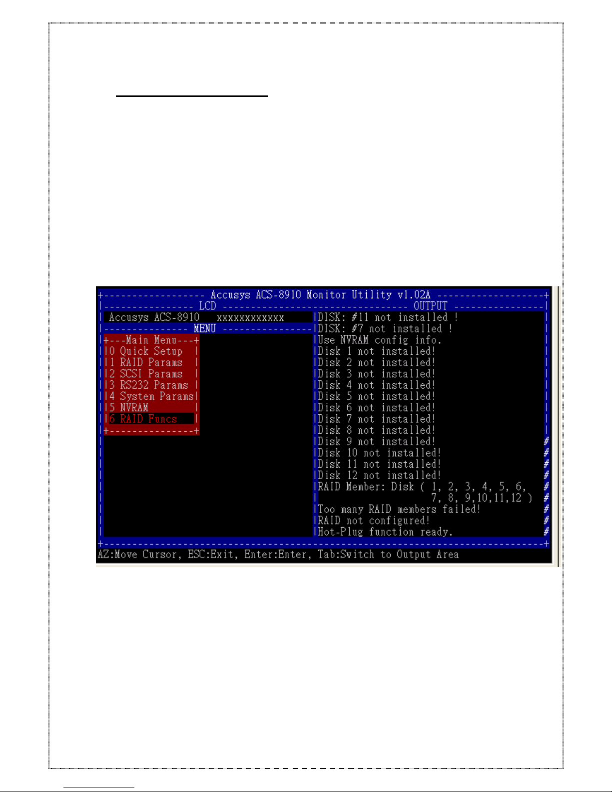
To start the monitor utility, from the remote terminal (or terminal emulation program)
press the [Ctrl]+[D] keys. This will invoke the Monitory Utility. Below is a sample of the
Monitor Utility. The display is the same for the Condre RAID.
At the top is the “ Monitor Utility” title which contains the model number and firmware
version of the Condre RAID. At the left is the “LCD” window. The contents displayed here
also appears on the front Panel LCD screen. Below is the “Menu” window with the Main
Menu options. To the right is the “OUTPUT” window that shows a more verbose
information about the Condre RAID. At the bottom are the instructions on how to navigate
using the Monitor Utility.
52
Page 53

6.3.1 Running Configuration Mode
Configuration Mode through the monitor utility is similar to the LCD display. However, it
has a graphical interface that allows for easier navigation through the menu system.
6.3.2 Updating the Firmware
The embedded firmware of the Condre RAID can be updated through the RS-232 port
using a terminal or PC in terminal emulation mode. When updating the firmware make
sure the Condre RAID is disconnected from the system to avoid any data loss.
Verify the terminal, or terminal emulation software, settings (Baud rate, Stop bit, Data bit,
Parity, Flow control) match the RS-232 settings of the Condre RAID. The Flow control must
be set to Software control (XON/XOFF) and the file transfer protocol must be set to
ASCII.
To update the firmware, perform the following steps.
NOTE: Refer to section Key Definitions under ANSI Terminal for information on how
to navigate when running the Monitor Utility.
1. Start the Monitor Utility by pressing the [Ctrl]+[D] keys.
2. Go to the ”Menu” section by pressing the [Tab] key.
3. Press the [ENT] key to open the ”Main Menu” menu.
4. Go to the “6 RAID Params” menu.
5. Go to the “69 Update ROM” menu and press the [ENT] key.
6. When prompted ”Are you ready to download the new firmware? (Y/N)” ENT [Y] to
continue.
7. When prompted ”Are you sure? (Y/N)” enter [Y] to confirm.
8. Press “ALT+T” then press “T”
9. Choice the new firmware file from your disk drive.
10. When prompted ”Begin firmware transfer now.” begin the file transfer.
11. From the terminal or terminal emulation program, go to the location where the new
firmware file is located and begin the file transfer.
12. Once the file transfer is complete the screen will display a similar message:
File transfer complete
Checksum = xxxxx : OK.
New firmware transfer complete.
13. At the prompt ”Enter ’Go’ to update the firmware.” type ”Go” to continue.
14. At the prompt ”Enter ’Go’ to reconfirm.” type ”Go” to continue.
53
The firmware will be programmed and the Condre RAID will automatically restart once
completed. The firmware upgrade is done.
Page 54

7 Troubleshooting
Problem: Condre RAID is not properly identified by the SCSI adapter during the
initialization of you computer system.
Possible Cause: The SCSI ID set for the Condre RAID is used by another SCSI device
attached to the same SCSI adapter.
Fix: Through the Configuration Mode select SCSI Params, then Set SCSI ID, and
specify a different SCSI ID. Also, most SCSI host adapters provide a onboard ROM
BIOS, or software utility, that displays the devices attached and their SCSI ID.
Disconnect the Condre RAID from the SCSI host adapter and during the system boot, or
by running the utility, note the SCSI ID already in use. This will select a SCSI ID for
the Condre RAID.
Problem: The Condre RAID is identified at all SCSI ID.
Possible Cause: The SCSI ID set for the Condre RAID is identical to the reserved SCSI
ID used by the SCSI adapter in your computer system.
Fix: Use the Configuration Mode to configure the Condre RAID for a different SCSI ID.
Remember the majority of SCSI host adapter reserves SCSI ID 7 for the adapter ID.
Problem: The Condre RAID is not been detected by the SCSI host adapter.
Possible Cause: Incorrect termination in a daisy chain configuration or a loose cable in
a stand-alone configuration.
Fix: In a daisy chain configuration verify only the SCSI host adapter and the last SCSI
device is terminated. To change the termination settings of the Condre RAID use the
SCSI Params menu and SCSI Termination option to enable or disable termination.
Problem: Unable to access the Condre RAID after the operating system boots up.
Possible Cause: The Condre RAID is not configured.
Fix: Make sure the Condre RAID is configured for a RAID level. If no RAID level is
configured the operating system will not detect the Condre RAID as a disk drive.
Problem: Unable to access the Configuration Mode using the remote terminal
interface.
Possible Cause: The terminal communications settings are not matching the settings
of the Condre RAID RS-232 interface.
54
Fix: The default settings for the RS-232 port are 19200 Baud rate, 8 Data bits, 1 Stop
bit, No Parity, and XON/XOFF Flow control. Make sure the terminal is configured for
Page 55
these settings. If the settings were changed during Configuration Mode verify the
settings of the Condre RAID in the RS-232 Params, Terminal option and change the
terminal settings accordingly.
Problem: Unable to send a Page or FAX using the modem port.
Possible Cause: The Page and Fax options are not enabled.
Fix: Go to the Configuration Mode and enable Page and FAX notification via the
System Params menu option.
Possible Cause: The default modem initialization string is not compatible with your
modem.
Fix: Change the modem initialization string in the System Params option. Refer to your
modem manual for its initialization string.
The following modem models require their own initialization strings.
Modem Model Initialization
String
Baud Rate FAX Class
Motorola
ModemSURFR V.34
28.8
AT&D\Q1E
Up to 38400
1 & 2
Multitech
Multimodem
2834ZDX
AT&D0&E5E0
Up to 38400
2 only
Hayes
Accura 288
V.34+FAX
AT&D0&K4E0 38400 only 1 & 2
Practical Peripherals
PM144MT II
AT&K4
Up to 38400
2 only
GVC
F-1128V/T2
AT&D0&B1&H2 38400 only 1 & 2
US Robotics
Sportster 28800
AT&H2&I1&R1&B1 38400 only 1 only
55
Page 56

Problem: The front panel LCD displays alternating “Zz” characters.
Cause: These characters are displayed when the cache is full with write request's
data that have not been processed. It will halt requests from the host to flush the data in
the cache.
Fix: None needed.
Problem: The front panel LCD displays alternating “Ww” characters.
Cause: These characters are displayed to indicate the write requests in the cache are
being processed. When these characters are displayed, the Condre RAID will halt
requests from the host (see above).
Fix: Make sure the “WRITE BUFFER” option of the “RAID Params” menu is enabled.
In addition, more cache memory may be required. By increasing the cache memory
the write buffer space increases and will be able to handle the higher write requests.
Problem: Newly installed memory fails during Self-Test or is not detected.
Possible Cause: Memory SO-DIMM module may not be properly seated or may not be
supported by the particular Condre RAID model.
56
Fix: Re-sit the memory module in to the socket and retry. If it continues to fail try
moving it to the other memory socket. Make sure the correct memory type is being
installed. The Condre RAID supports 144-pin SO-DIMM SDRAM.
Page 57
Appendix A - Error Messages
The following is a listing of the error messages generated by the Condre RAID and their
meaning.
Legend
:
x= Number of disk channel
y= Total number of disks detected by the
controller
z= Number of disks specified in 1 RAID
Params, 3 Disk Number menu option.
57
Error Message Explanation
Number of disks
found = y,
needed = z
The number of disks found (y) does not match the
number of disks configured for. The number of disks
needed (z) is required.
Disk x not
installed!
A disk drive (x) is not installed or is unable to be
accessed.
Disk x previously
removed!
A disk (x ) was removed due to a failed disk or by the
operator.
Too many RAID
members failed!
The minimum number of disks required for the RAID
configuration failed to initialize.
RAID not
configured!
RAID can not be configured due to too few good disks
available or no RAID configuration has been performed.
Disk x is too
small!
A disk capacity being added to an existing RAID
configuration is less than the configured disks. To add a
disk to an existing configuration the disk must be the
equal size or greater.
Disk x format
ERROR!
Disk (x) failed during the format. Possible bad disk.
Init RAID5
ERROR!
The RAID 5 initialization failed. Possible bad disk. Use
Disk Check to identify faulty disk.
Disk x add
ERROR!
Disk (x) being added failed. Possible bad disk. Use Disk
Check to identify faulty disk.
Parity ERROR:
blk ? !!
A parity byte was unable to be read/write. Blk ? is the
block (sector) on the disks that failed. Possible bad disk.
RAID 5 Check
ERROR!
The R5 Check function failed. Possible wrong RAID
configuration or not initialized (Init RAID5).
UPS interrupt
detected !
A power outage was detected by the UPS and notified the
ProRAID via the UPS port
Param vendor
ID ERROR!
The information in NVRAM has been erased. The
configuration is lost.
Param
checksum
ERROR!
The information in NVRAM has been erased. The
configuration is lost.
SCSI chip
ERROR!
The SCSI interface of the ProRAID controller is faulty.
Te st ing Serial The RS-232, Modem, or UPS port is faulty.
Page 58
58
Connection…
Fail
Do_IDE_Cmd:
wait DRQ
The IDE interface is waiting for DRQ signal to go off in
command phase.
Do_IDE_Cmd
ERROR ? !
An error (?) occurred in IDE interface. Use Disk Check
to identify faulty disk channel.
IDE_ISR: wait
Master Int
IDE interface is waiting for an interrupt from a disk.
IDE_ISR: wait
IDE Busy off
IDE interface is waiting for disk to be free.
IDE_ISR:
status ?
IDE disk drive current status (?)
IDE_ISR: wait
DRQ
To wait for disk drive to turn off DRQ in Interrupt phase.
IDE_ISR: DRQ
ON
Indicates DRQ is not free in Interrupt phase.
DISK: status ?,
error: ? !!
The status (status ?) and error (error: ?) returned by the
disk based on the ATA-2 Specification.
DISK: #X
type=?, blkno=?,
resid=?
The disk (x) failed to respond to a request by the
controller (type=?). The block number (blkno=?) where
the request failed. The remaining sectors (resid=?)
DISK: Initialize
#? ERROR!
The disk (x) was unable to be initialized by the controller.
Possible bad disk.
DISK: #x is
off-line!
Disk number (x) failed and was removed from the RAID
configuration.
DISK: #x not
installed!
The disk (x) is not detected by the controller. Possible
bad disk.
DISK: #x
ERROR
status ? !
The disk (x) caused an error. The status (?) returned by
the disk per ATA-2 Specification.
ERROR: Not a
hard disk!
The controller does not recognize the device installed.
ERROR: Disk
parameters
ERROR!
The controller was unable to read the disks parameters
(Cylinder, Heads, Sectors, Multi-Sector). Possible bad
disk.
Error Message Explanation
ERROR: No
multi-sector
mode!
The disk does not support the ATA-2 multi-sector transfer
function. The disk is an older IDE disk.
ERROR: IORDY
not support!
Disk does not support IORDY. Possible older IDE disk
that does not support ATA-2 Specification. Must replace
disk.
DISK: #? Remap
area overflow !
The area used to re-map bad sectors is full.
DISK: #? Blk
no: ? is
remapped.
Block number (?) is detected as a bad sector and has
been re-mapped.
DISK: #? Remap
area is empty!
No re-map sectors are available while the controller
detected bad sectors.
Modem time-out! The modem did not respond to the page or FAX
notification re
q
uest. Modem may be turned off or not
Page 59
connected.
All modem
operations are
canceled!
User stopped the modem from sending a page or FAX
notification.
Training FAIL! Fax Class 1 support -- modem fails in training phase.
Page transfers
FAIL!
The page notification failed. Modem may be turned off
or not connected.
FAX: Modem is
busy!
The modem is currently is use and unable to send a FAX
notification.
Paging: Modem
is busy!
The modem is currently is use and unable to send a page
notification.
Invalid NVRAM The information stored in the NVRAM area is invalid and
unable to be used.
No Configuration The ProRAID is currently not configured for any RAID
level.
Config ERROR The current configuration failed to be verified. Possible
fault disk or disk off-line.
Not enough Disk Number of disks required for the RAID Level is missing.
Possible faulty disks or disks off-line.
Fail Fan The cooling fan of chassis is failed.
WARM Temp The inside temperature of chassis is too high.
Fail Power The redundant have occurred error.
59
Page 60
APPENDIX B : Technical Specifications
Condre RAID Disk Array Controller
Operation System OS independent and Transparent
CPU Intel 80303 64-bit RISC microprocessor
SCSI I/O Processor LSI 53C1010R Ultra160
RAID Level 0,1,3,5,0+1
Cache Memory One 144-pin SO-DIMM , 32~ 512 MB
Battery Backup Yes (option)
SCSI Bus Termination: Active Termination, software configurable
SCSI Architecture Multiple ID & Multiple LUN
SCSI Channel to Host 2(Max) Ultra 160
IDE Disk Channel Up to 16 x IDE ATA-100/133
Data Transfer Rate Up to 160MB
Tagged Command
Queuing
Yes, up to 256 Commands
Stripe Size Variable
Write Option Write
through
Write through or Write Back
Hot Swap Yes
Hot Spare Yes (rebuild Transparently & Automatically)
On Line Expansion Yes
User Friendly GUI man Yes
Remote Management RS-232 terminal emulation for configuration and
monitoring
Remote Alarm Fax, Pager
Beeper Alarm Yes
Controller Size: H 40.7 mm x W 150mm x D 197mm
Operating Temperature:
5°C to 45°C (41°F to 113°F)
60
Note: Specifications subject to change without notice.
Page 61
APPENDIX C : SCSI Cable Specifications
SCSI Standards, Cable Length and corresponding Maximum Possible Drive
Connections
Single-Ended Differential Ultra2 Maximum Drives
SCSI-1 6 m 25 m 8
SCSI-2 3 m 25 m 8
Wide SCSI-2 3 m 25 m 16
Ultra SCSI-2 1.5 m 25 m 8
Ultra SCSI-2 3 m - 4
Ultra Wide SCSI-2 - 25 m 16
Ultra Wide SCSI-2 1.5 m - 8
Ultra Wide SCSI-2 3 m - 4
Ultra 2 Wide SCSI 12m 16
Ultra160 SCSI 12m 16
SCSI Bus Width and Maximum Throughput
61
Bus
Width
SCSI Bus
Sync. Frequency
Max. Bus
Throughput
SCSI ID
Up to
SCSI-1 8-bit Asynchronous 5 MB/Sec 7
(Fast) SCSI-2 8-bit 10 MHz 10 MB/Sec 7
(Fast) Wide
SCSI-2
16-bit 10 MHz 20 MB/Sec 15
Ultra SCSI-2 8-bit 20 MHz 20 MB/Sec 7
Ultra Wide SCSI-2 16-bit 20 MHz 40 MB/Sec 15
Ultra 2 SCSI 16-bit 40 MHz 80 MB/Sec 15
Ultra 160 SCSI 16-bit 80 MHz 160 MB/Sec 15
Page 62

APPENDIX E : Glossary
Array Management Software, Firmware
The body of software that provides common control and management for a disk array.
Array Management Software most often executes in a disk controller or intelligent host
bus adapter, but may also execute in a host computer. When it executes in a disk
controller or adapter, Array Management Software is often referred to as Firmware.
Disk Array
A collection of disks from one or more commonly accessible disk controllers, combined
with a body of Array Management Software. Array Management Software controls the
disks and presents them to the array operating environment as one or more virtual
disks.
Disk Striping
Data distributed across all the disks in the array. There is no redundant information
generated or stored.
Disk Mirroring
Data is duplicated on different sets of disks in the array.
Host Computer
Any computer system to which disks are directly attached and accessible for I/O.
Mainframes, and servers, as well as workstations and personal computers, can all be
considered host computers in the context of this book, as long as they have disks
attached to them.
Hot Spare
The substitution of a replacement unit in a disk system for defective one, where the
substitution can be performed while the controller is running.
Hot Swap
The substitution of a replacement unit in a disk controller for a defective one, where the
substitution can be performed by the controller itself while it continues to perform its
normal function. Hot Swaps do not require human intervention (i.e., hot spare)
Member Disks
62
Disk channels configured for a particular RAID Level. Member disks are identified by a
status of ” displayed on the front panel LCD.
Page 63

Mirroring
A form of RAID in which Array Management Software maintains two or more identical
copies of data on separate disks.
MTBF
An abbreviation for Mean Time Between Failure, the average time from start of use to
failure in a large population of identical components or devices.
RAID
A Redundant Array of Independent Disks (RAID or RAID array) is a disk array in
which part of the storage capacity is used to store redundant information about user
data stored on the remainder of the storage capacity. The redundant information
enables regeneration of user data in the event that one of the array member disks or
the access path to it fails.
RAID levels
The original RAID level 1 through 5 was outlined in a research paper entitled A Case for
Redundant Arrays of Inexpensive Disks. This paper was published in 1988 by David A.
Patterson, Garth Gibson, and Randy H. Katz of the University of California at Berkley.
Counting the term RAID 0 that refers to disk striping and later defined RAID 6, there are
7 levels of RAID.
SCSI
Small Computer System Interface.
Spare, Spare Disk
A disk reserved for the purpose of substituting for a like entity in case of failure of that
entity.
Swap
63
The installation of a replacement unit in place of a defective unit. Units are parts of a
disk controller that may either field replaceable by a vendor service representative or
consumer replaceable.
Page 64
APPENDIX F : Record the Condre RAID Setting
F.1 View Drive Information
64
Channel Brand Model Capacity
1 GB
2 GB
3 GB
4 GB
5 GB
6 GB
7 GB
8 GB
9 GB
10 GB
11 GB
12 GB
13 GB
14 GB
15 GB
16 GB
Page 65
F.2 RAID Params Information
RAID Level
□ 0 □ 1 □ 0+1 □ 3 □ 5
Disk Number
□1 □2 □3 □4 □5 □6 □7 □8
□9 □10 □11 □12 □13 □14 □15 □ 16
Spare Disk
□ No □ Ye s Channel _____________
Slice 0 __________ GB
Slice 1 __________ GB
Slice 2 __________ GB
Slice 3 __________ GB
Slice 4 __________ GB
Slice 5 __________ GB
Slice 6 __________ GB
Slice 7 __________ GB
65
Page 66
F.3 SCSI Params Information
Primary
SCSI lD
□ 0 □ 1 □ 2 □ 3 □ 4 □ 5 □ 6 □ 7
□ 8 □ 9 □10 □11 □12 □13 □14 □15
Termination
□ Enable □ Disable
TAG Queuing
□ Enable □ Disable
Speed
□ Ultra2 □ Ultra160
Ultra
□ Enable □ Disable
Wide
□ Enable □ Disable
LUN 0 to Slice
□ 0 □ 1 □ 2 □ 3 □ 4 □ 5 □ 6 □ 7
LUN 1 to Slice
□ 0 □ 1 □ 2 □ 3 □ 4 □ 5 □ 6 □ 7
LUN 2 to Slice
□ 0 □ 1 □ 2 □ 3 □ 4 □ 5 □ 6 □ 7
LUN 3 to Slice
□ 0 □ 1 □ 2 □ 3 □ 4 □ 5 □ 6 □ 7
LUN 4 to Slice
□ 0 □ 1 □ 2 □ 3 □ 4 □ 5 □ 6 □ 7
LUN 5 to Slice
□ 0 □ 1 □ 2 □ 3 □ 4 □ 5 □ 6 □ 7
LUN 6 to Slice
□ 0 □ 1 □ 2 □ 3 □ 4 □ 5 □ 6 □ 7
LUN 7 to Slice
□ 0 □ 1 □ 2 □ 3 □ 4 □ 5 □ 6 □ 7
66
Page 67
67
Secondary
SCSI lD
□ 0 □ 1 □ 2 □ 3 □ 4 □ 5 □ 6 □ 7
□ 8 □ 9 □10 □11 □12 □13 □14 □15
Termination
□ Enable □ Disable
TAG Queuing
□ Enable □ Disable
Speed
□ Ultra2 □ Ultra160
Ultra
□ Enable □ Disable
Wide
□ Enable □ Disable
LUN 0 to Slice
□ 0 □ 1 □ 2 □ 3 □ 4 □ 5 □ 6 □ 7
LUN 1 to Slice
□ 0 □ 1 □ 2 □ 3 □ 4 □ 5 □ 6 □ 7
LUN 2 to Slice
□ 0 □ 1 □ 2 □ 3 □ 4 □ 5 □ 6 □ 7
LUN 3 to Slice
□ 0 □ 1 □ 2 □ 3 □ 4 □ 5 □ 6 □ 7
LUN 4 to Slice
□ 0 □ 1 □ 2 □ 3 □ 4 □ 5 □ 6 □ 7
LUN 5 to Slice
□ 0 □ 1 □ 2 □ 3 □ 4 □ 5 □ 6 □ 7
LUN 6 to Slice
□ 0 □ 1 □ 2 □ 3 □ 4 □ 5 □ 6 □ 7
LUN 7 to Slice
□ 0 □ 1 □ 2 □ 3 □ 4 □ 5 □ 6 □ 7
Page 68
F.4 RS-232 Params Information
F.4.1 Modem Params Information
Baud Rate
□ 2400 □4800 □9600 □14400 □19200
□28800 □38400 □57600 □115200
Stop Bit
□ 1 □ 2
Data Bit
□ 1 □ 2
Parity
□ None □ Odd □ Even
F.4.2 Terminal Params Information
Baud Rate
□ 2400 □4800 □9600 □14400 □19200
□28800 □38400 □57600 □115200
Stop Bit
□ 1 □ 2
Data Bit
□ 1 □ 2
Parity
□ None □ Odd □ Even
68
Page 69
F.5 System Params Information
F.5.1 Password Information
Passwd Check
□ Enable □ Disable
Set Password Default :00000000
New : ______________
F.5.2 Pager Information
Paging
□ Enable □ Disable
Pager 1 No Tel No. : _____________________
Pin No. : _____________________
Code _________________________
Pager 2 No Tel No. : _____________________
Pin No. : _____________________
Code _________________________
Repeat
□ 20 □ 15 □ 10 □ 5
Interval
□ 20 □ 15 □ 10 □ 5
69
Page 70
F.5.3 Pager Information
FAX
□ Enable □ Disable
FAX Class
□ 1 □ 2
FAX 1 No. _________________________
FAX 2 No. _________________________
Repeat
□ 20 □ 15 □ 10 □ 5
Interval
□ 20 □ 15 □ 10 □ 5
F.5.4 Company Information
String 1 _________________________
String 2 _________________________
F.5.5 Modem Information
Modem Initialize String
( Hays )
Default : AT&D0&K4E0
Brand _________________________
Initialize String _________________________
F.6 View Condre RAID Controller Information
Cache Size
□64MB □128MB □256MB □512MB
Capacity __________ GB
Firmware version _____________
Serial Number ___________________________
RAID Member ___________________________
70
 Loading...