

Condor UBL-8000 Urban User Instruction Manual
1
CONDOR UBL-8000 Urban BIKE LOCK USER INSTRUCTION MANUAL
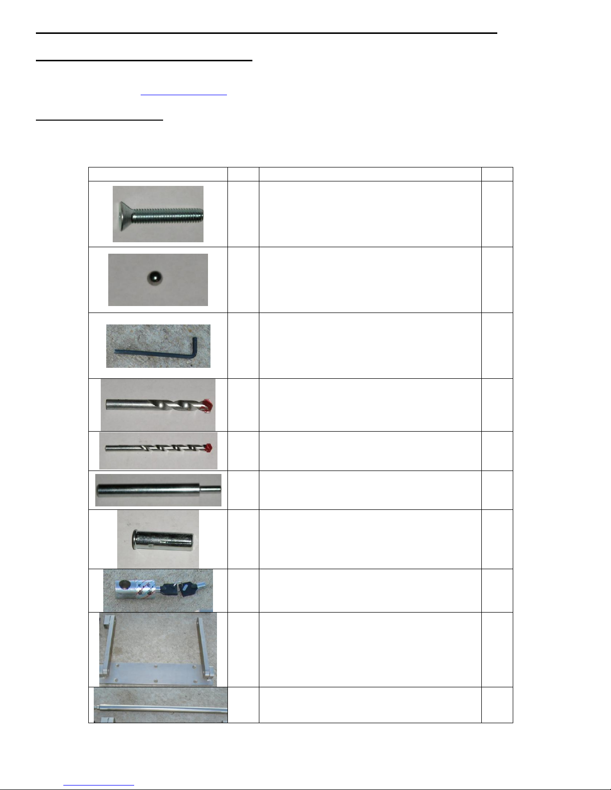
Component Photo
Item
Component Description
QTY
A
Flat Head Socket Cap Screws
3/8”-16 x 2”
6
B
Steel ball bearing
6mm
6
C
Hex key Alan Wrench 7/32
1
D
1/2” Concrete Drill bit
1
E
3/8” Concrete Drill bit
1
F
Anchor Sleeve tool
1
G
Concrete Anchor Sleeve
3/8” x 1½"
6
H
Lock & Keys
1
I
Urban UBL-8000 Main Frame
1
J
Urban UBL-8000 1” x 24” Round Securing Rod
STOP! WARNING: READ THIS FIRST!
First read and understand the instruction manual and product labels for important safety, set-up and troubleshooting information. If
you have problems setting up or using the UBL-8000 Urban Bike Lock by CondorTM , contact customer service @ 1-815-754-7418
or contact us via email @ www.condor-lift.com. The UBL-8000 Urban Bike Lock by CondorTM is not intended for use by
children.
Components in Package:
Remove all parts from shipping box, check the parts below to make sure you have all the parts needed to assemble your CondorTM
UBL-8000 Urban Bike Lock before beginning. In the unlikely event that you find a damaged or missing part, please call customer
support service at (815) 754-7418.

2
Note: If the following sequential instructions for securing the UBL-8000 are not followed correctly,
The six concrete anchors will not lineup correctly with the unit. The kit included is for installation in concrete and
pavement. If installed into trailer, a trailer bolt kit is available.
Installation Instructions:
The UBL-8000 Urban Bike Lock is comprised of three main components; one Main Frame Unit (item I), one 1” x 24” Round
Securing Rod (see item J), and one Lock & Keys set (item H). The Main Frame unit is to be securely bolted (see anchoring
instructions below) to the ground using the existing hole locations of the Main Frame. Once the Main Frame unit is securely
attached to the surface area, the motorcycle is placed above the UBL-8000, the swiveling arms are raised and the 1” x 24” Round
Securing Rod is inserted through the existing holes located on the ends of the arms through the wheel and into the Lock, making
sure that the lock is positioned into the lock housing with the key insert hole facing down. After making sure that the Round
securing rod is inserted completely into the lock, turn and remove the key. The UBL-8000 can be used to secure the motorcycle
using the front or rear wheel. Please see the following installation instructions below.
1. Begin installation by first choosing the most relevant & suitable location for anchoring your UBL-8000. Your Urban bike Lock
comes with most all of the required hardware and tools for anchoring into a concrete surface. You will only need a hand held
drill (preferably one with a hammer feature) for drilling into the concrete surface, a standard hand held hammer, and a marker
or pencil.
2. Place the Main Frame Unit on a concrete surface, choosing only one of the corner counter sunk hole locations, and mark the
concrete with a pencil or marker, remove the Main Frame Unit out of the way so that you may begin the drilling process.
3. Place the 3/8” concrete drill bit (Item E) into the hand held drill and start by drilling only the 1 hole location you marked . You
want to drill at least 2 inches deep into the concrete.
4. Once you have completed drilling the first hole with the 3/8” drill bit, you then need to expand the hole using the 1/2” concrete
drill bit (Item D) to the same depth as the initial hole. Make sure the hole is clear of all dust and debris.
5. Once the first hole has been drilled, insert one of the Concrete Anchor Sleeves with the lip facing up into the hole and tap the
sleeve into the hole using a hammer. Once the upper lip f the Anchor Sleeve is flush with the ground, you will need to flare out
the base of the sleeve using the Anchor sleeve tool (Item F). Note: Make sure the Anchor Sleeve is flush with the ground
surface prior to moving on to the next step. If the sleeve is not flush, it will need to be removed and the hole will need to be
drilled deeper. See Fig 1.
6. Once the top of the Anchor Sleeve is flush with the surface, place the Anchor Sleeve Tool inside the hole and tap it downwards
into the Anchor Sleeve hole using a hammer. This is necessary so that the Anchor Sleeve can be flared out inside the hole
preventing it from spinning when the screw is inserted and tightened.
7. Position the Main Frame Unit back onto its initial desired location, making sure to align the newly set anchor with the
appropriate hole used for marking. Secure the Unit to the ground using a Flat Head Socket Cap Screws 3/8”-16 x 2” (Item A)
and tighten down with the 7/32 Hex key Alan Wrench (Item C). See Fig.2
8. You are now ready to begin working on the second hole. Using the 3/8”concrete drill bit (Item E), drill the hole at the opposite
corner of the Main Frame Unite base while it’s still in place, making sure that the hole to be drilled is deep enough.
9. Once the 3/8” hole is drilled loosen the first screw enough so that the Main Frame Unit can be rotated away from the second
drilled hole. By doing so, you eliminate the need for having to remove the unit entirely. You are now ready to drill the second
hole using the 1/2” concrete drill bit (Item D).
10. Drill the second hole using the 1/2” concrete drill bit (Item D) and clear any debris from the and around the hole and repeat
steps 5 and 6. See Fig 3.
11. Rotate the unit back around and line up the second hole. Secure the unit down using another Flat Head Socket Cap Screws
3/8”-16 x 2” (Item A) and tighten down both the first and second screws with the 7/32 Hex key Alan Wrench (Item C).
12. With the unit secured in place by two screws, you can now drill the remaining 4 holes using the 3/8” concrete drill bit (Item A).
See Fig 4. One again, be sure to acquire sufficient depth for the anchors when drilling.
13. Once all remaining 3/8” holes are drilled, remove the Main Frame Unit, and re-drill the remaining hole using the 1/2” concrete
drill bit (Item D) and repeat steps 5 and 6 for each remaining hole.
14. Once all anchor sleeves are in place and flared out, place the unit back into position and tighten down using all six Head Socket
Cap Screws 3/8”-16 x 2” (Item A). Do not bring down and tighten any screw until all six screws have threaded into the sleeve.
15. Once the unit is securely tighten down, Place the 6 mm Steel ball bearings (Item B) in the Head Socket Cap Screws 3/8”-16
x 2” (Item A) Alan wrench tool hole opening and hammer the ball into the screw top. See Fig 5 & 6. You should have a couple
of extra 6 mm ball bearings incase loss or shortage. Be sure to do this for all six screws. See Fig 7.
16. Roll the motorcycle wheel over and on the Main Frame Unit making sure that the bike will remain centered after it’s leaned to
one side on the kickstand. Raise the Main Frame swivel arms and insert the Hercules HBL-8000 1” x 24” Round Securing Rod
(Item J). For some motorcycles, you might need to adjust the through hole location in the wheel rim by bringing the bike out
and back in to the unit at a different tire rotation before inserting the Securing Rod.
17. Once the Securing Pin is in Place, position the lock into the swivel arm housing with the key hole facing down. Make sure that
the Rod is positioned inside the lock, turn and remove the key. Note: the key will not come out if it’s not in the locked position.
See Fig 8. Note: By attempting to pull the bar out after the key is removed, you should be able to verify that it is securely
positioned into the lock. Motorcycles may also be secured using the rear tire. See Fig 9
 Loading...