

Condor MDR 5-K, MDR 5 Operating Instructions Manual
Page 1 of 2
Montageanweisung
Operating Instructions
Instrucciones de Montaje
Instructions de Montage
Instruzioni d’impiego
MDR 5 / MDR 5-K
Druckschalter / Pressure switch
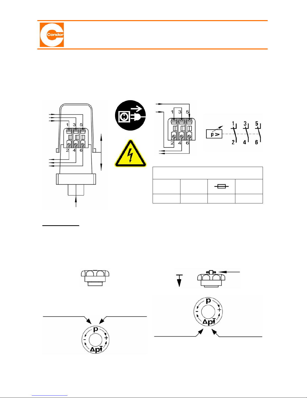
The relevant standards for running and installing electrical appliances are to be observed.
Installation and connection by skilled personnel only, after installing accessories function
of device to be checked by skilled personnel only.
2 ~
3 ~
EN/IEC 60947 - 4 - 1 (AC-3)
Iq
I
the
Typ “2“
NH00 / gL
UN
(50/60 Hz)
3 kA 25 A 50 A 500 V~
CAUTION: Pressure setting is only possible when applying
pressure to the switch
Cut-out pressure po
Differential Δ
p
Δ
p = po – pu
Press wheel downwards
If the spindle moves when turning, lowest
possible Δp has been reached. In order to
loosen, turn wheel to the left holding the
spindle tight.
P
IP 54
po lower:
turn wheel
to the left
po higher:
turn wheel
to the right
Δ
p
lower:
turn wheel
to the right
Δ
p
higher:
turn wheel
to the left
Spindle
Page 2 of 2
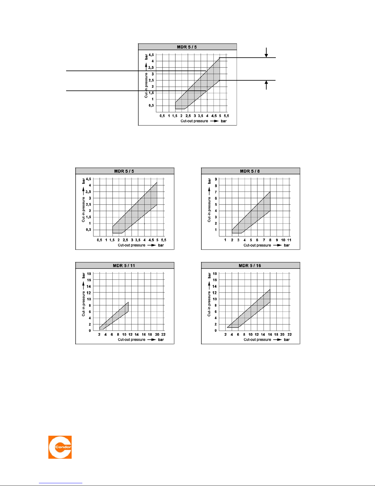
Example of a pressure setting using the MDR 5/5 pressure diagram
Pressure Diagrams MDR 5
02.11.2005
Condor Pressure Control GmbH
Warendorfer Straße 47 – 51
D-59320 Ennigerloh
Telefon: +49 (0) 25 87 / 89 – 0
Telefax: +49 (0) 25 87 / 89 - 140
info@condor-cpc.com
www.condor-cpc.com
3.2
max.
cut-in pressure
1.8
min.
cut-in pressure
Setting range off
the cut-in pressure
Example:
Cut-out pressure po 4 bar
Cut.in pressure pu between
1.8 and 3.2 bar possible
 Loading...