

Page 1
Quick Start Installation Guide
Mounting
Plumbing
Electrical
Steam Distribution
Page 2
Mounting
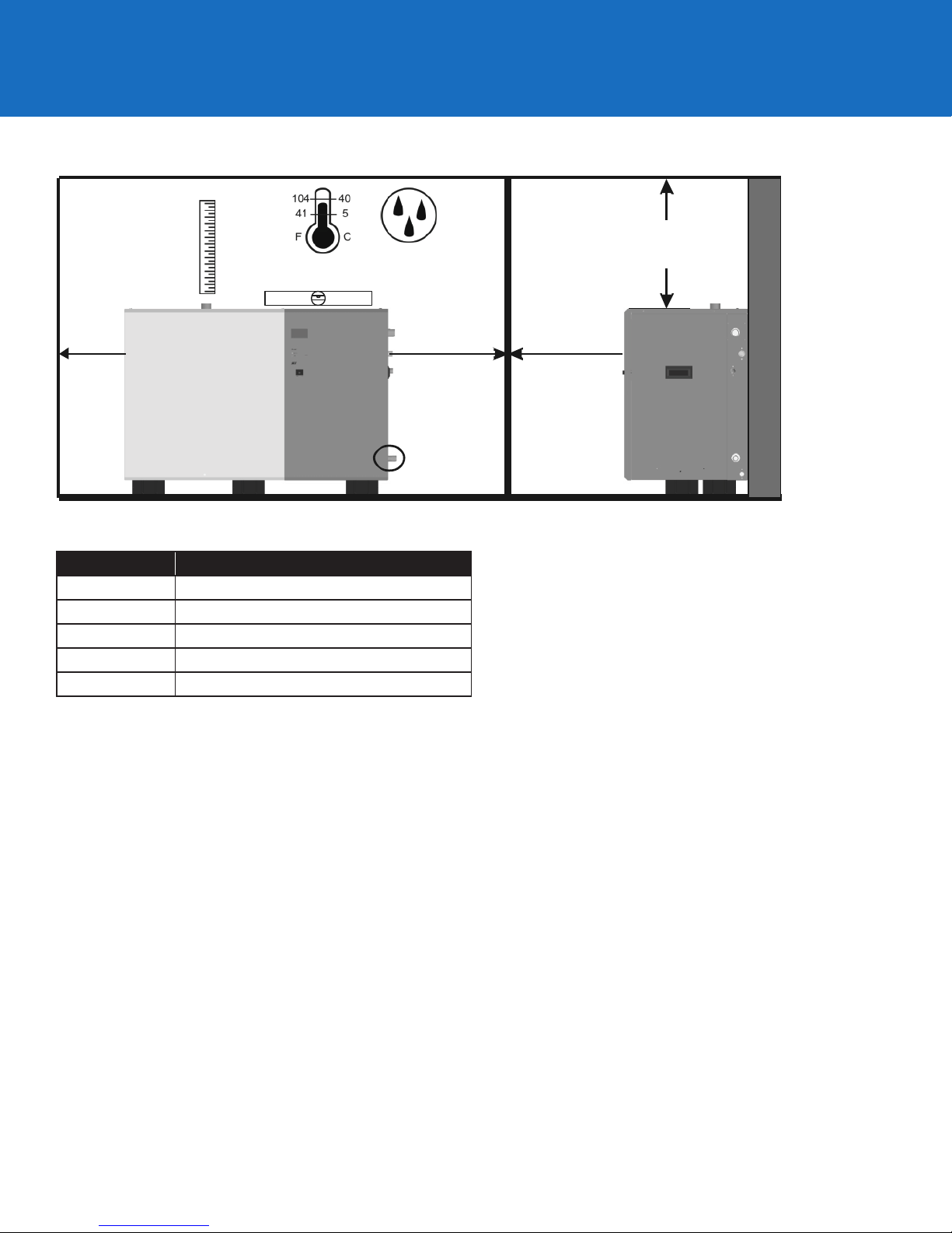
As Close as
Possible to Steam
Distributor
Mount
HumidierLevel
5-95%
36 in. (91 cm) Min.
Top Clearance
(0 in. for Nortec SE50 only)
30 in.
(76 cm)
Min.
Nortec
SE 1050
only
Model Net/Full Weight – lbs (kg)
50 125/180 (57/82)
100-175 267/423 (121/192)
250-375 355/599 (161/272)
525-750 529/992 (240/450)
1050 703/1384 (318/628)
30 in.
(76 cm)
Min. Side
Clearance
Condensate drain
line must be
sloped down, do
not use to lift
condensate
30 in.
(76 cm)
Min. Front
Clearance
* NOTE: Condensate drain line must be sloped downward to
boiler condensate return. Use pump (by others) or stand
(optional) if necessary.
Mounting
Mount either oor mounted or on a mounting stand (stand
optional). Nortec SE 50 models can also be ceiling mounted
with the optional ceiling installation kit, part number 2520345.
1. Install on a level platform in an area with ambient temperature
41-104 °F (5 – 40 °C) relative humidity 5-95% (non-condensing).
2. Ensure mounting surface is strong enough to support the full
weight of the humidier and accessories. If mounting on the
optional stand, assemble stand according to the instructions
provided with the stand and secure stand to the oor via the
holes in the leg support plates following any local codes or
regulations.
3. Install in location where the electrical power, boiler steam, and
drain lines can be connected.
4. Locate the humidier as close as possible to the steam
distributor location, net output will be reduced as a result of
heat loss through the steam line.
5. Condensate drain is located close to the bottom of the
humidier. Locate the unit so that condensate lines slopes
down to boiler or use pump (by others) to lift to boiler. Use
stand if necessary.
6. Avoid mounting humidier on combustible surfaces including
(but not limited to) carpet, tile, or certain insulating materials.
7. Clearance dimensions shown are for reference only and are
the minimum required for maintenance of the humidier.
Consult local and national codes before nal location and
installation.
8. location. Net output will be reduced as a result of heat loss
through the steam line.
Page 3
Plumbing
Water Supply
1. All water supply and drain line connections must be installed
in accordance with local plumbing codes. Condair accepts no
liability for installation code violations.
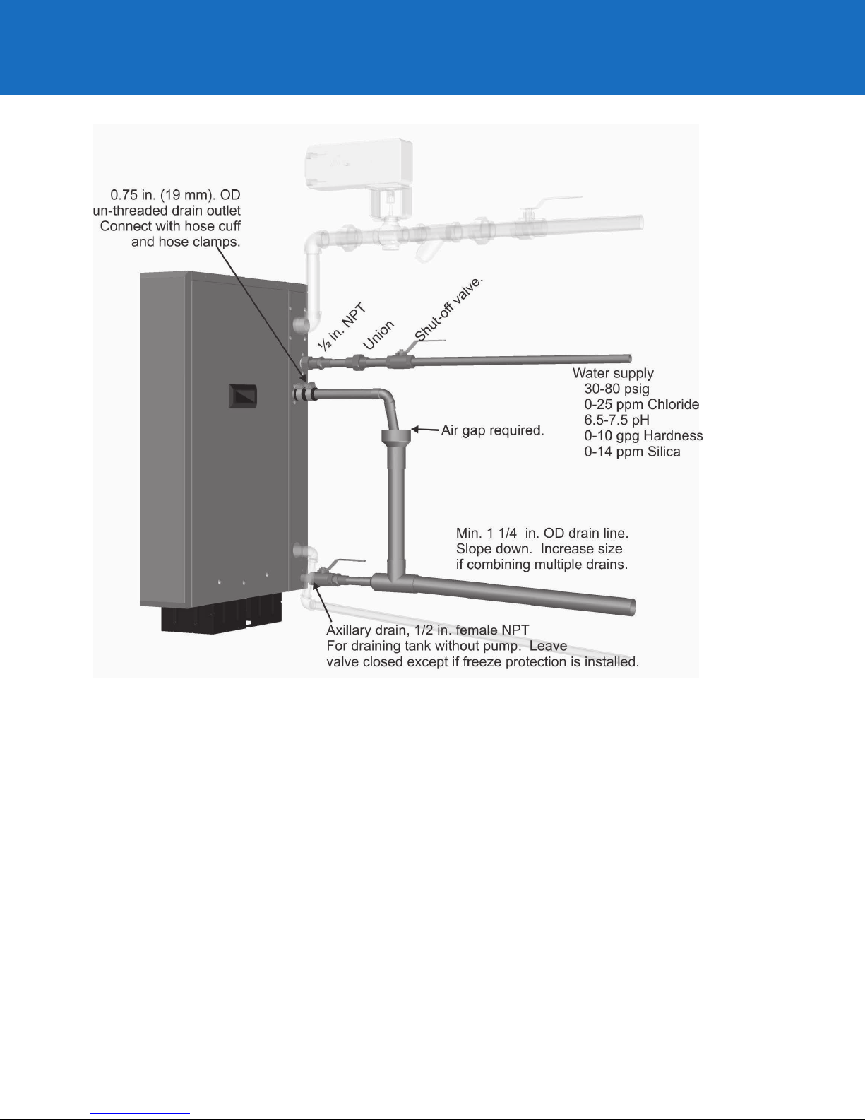
2. Install water shut o valve and union before humidier to
facilitate servicing.
3. Supply water requirements:
30 - 80 PSIG
Hardness 5-7 gpg
Chlorides 0-25 ppm
Alkalinity 7.5-8.5 pH
Drain Line(s)
1. Drain line should be a minimum of 1.25” OD copper,
sloped away to allow proper drainage.
2. Drain line must have an air gap installed within three feet
of the drain outlet.
3. Auxiliary drain connection with manual shut o valve
is recommended for all units. Valve to be left closed on
units without freeze protection option installed.
4. Drain Water is very hot, do not use plastic pipe for drain
or condensate lines, do not drain to public sink. Route to
oor drain or equivalent.
Page 4
Electrical
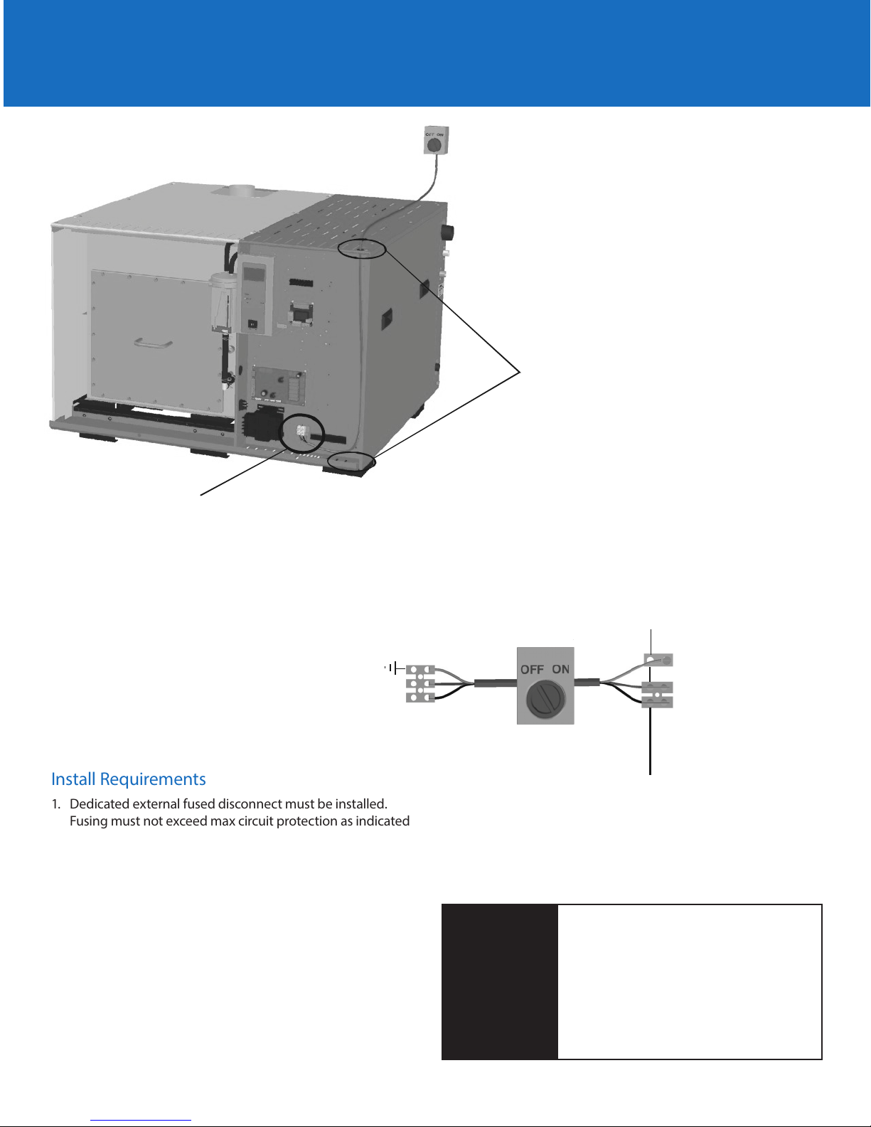
Knockouts provided
in top and bottom panels.
Install strain relief (by others)
High voltage
terminal block
Single Phase Supply
Ground
L1
Neutral
Install Requirements
1. Dedicated external fused disconnect must be installed.
Fusing must not exceed max circuit protection as indicated
on the specication label.
2. An electrical disconnect must be installed within view of the
humidier.
3. Ensure that adequate power is available to carry full
humidier amp draw as indicated on the specication label.
4. All wiring to be in accordance with national and local
electrical codes.
Nortec SETC / P Primary Power
Dedicated circuit
breaker or fused
disconect.
WARNING
Wiring needs to be preformed by a
licensed Electrician.
Ground
L1
Neutral
E
I
X
N
T
T
All Nortec SE humidiers operate on
120VAC, single phase, 60 Hz power.
Refer to specication label for power
requirements.
Page 5
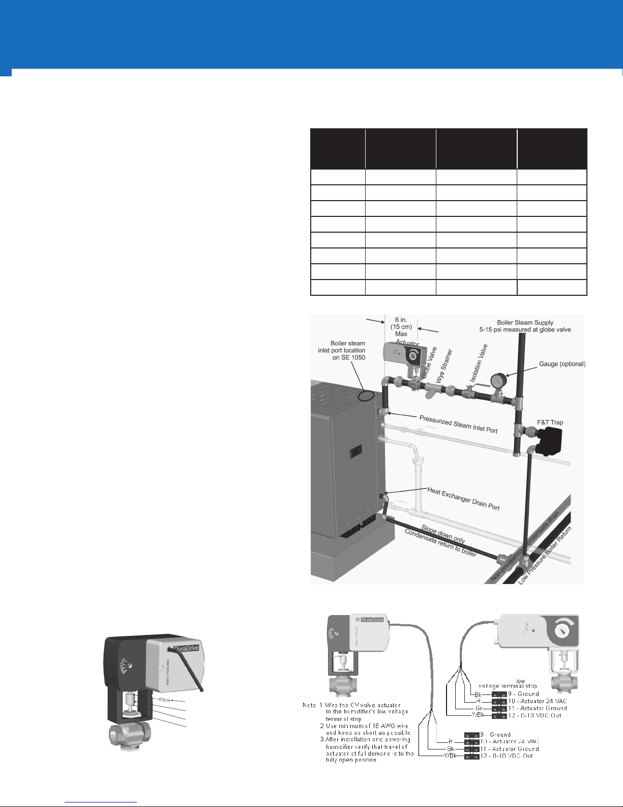
Pressurized Steam Supply
Jam Nut & Washer
Install Requirements
1. Boiler steam supply line design is the responsibility of the
installer. Condair does not accept liability for installation
code violations.
2. The Nortec SE will operate on supply steam pressures
between 5 and 15 psi measured at the globe valve. Pressure
exceeding 20 psi will damage the humidier. If connecting
via pressure reducing valve, install a safety relief valve to
prevent pressures in excess of 15 psi.
3. Boiler steam supply line must be designed so that that
design pressure is present at the globe valve when the
globe valve is completely open (100% demand).
4. Condair supplies a globe valve, actuator and wye strainer
with each Nortec SE humidier.
5. Humidier condensate drain should be returned to the
boiler and not mixed with water from the humidier tank or
auxiliary drains.
6. The steam supply pressure can be entered into the
Nortec SETC control software in the ‘Control Settings’ menu
to provide an accurate display of unit output. Pressure
Based on page 56 of the 2552940 Nortec SE Install and
Operations manual.
Supplied Component Port Size
by Humidier Capacity
Capacity Globe Valve
CV
Valve, Steam
Inlet, Wye Port
Condensate
Port (NPT)
(NPT)
50 2.8 ½” ¾”
100 5.5 ¾“ ¾”
175 10 1” ¾”
250 12 1” ¾”
375 20 1 ¼” ¾”
525 28 1 ½” 1 ¾”
750 40 2” 1”
1050 65 2 ½” 1 ¼”
Actuator Mounting
1. Install Jam nut and lock washer on globe valve stem.
2. Thread the stem extension onto the globe valve.
3. Mount the actuator to the globe valve and secure to the
valve with the mounting nut.
4. Extend the valve stem, fully closing the globe valve.
5. Load the actuator with the provided allen key, two full
turns clockwise.
6. Thread the stem extension until the extension pin hole
aligns to the actuator pin hole and secure with the
connecting pin.
7. Tighten the jam nut against the stem extension.
8. Ensure the valve completely closes when the actuator is not
powered.
Actuator
Nortec
SE 50 - 750
Actuator
Nortec SE 1050
Actuator
Nortec SE 1050
Connecting Pin
Stem Extension
Mounting Nut
Globe
Valve
Nortec SE 50-750 Terminal Strip
Page 6
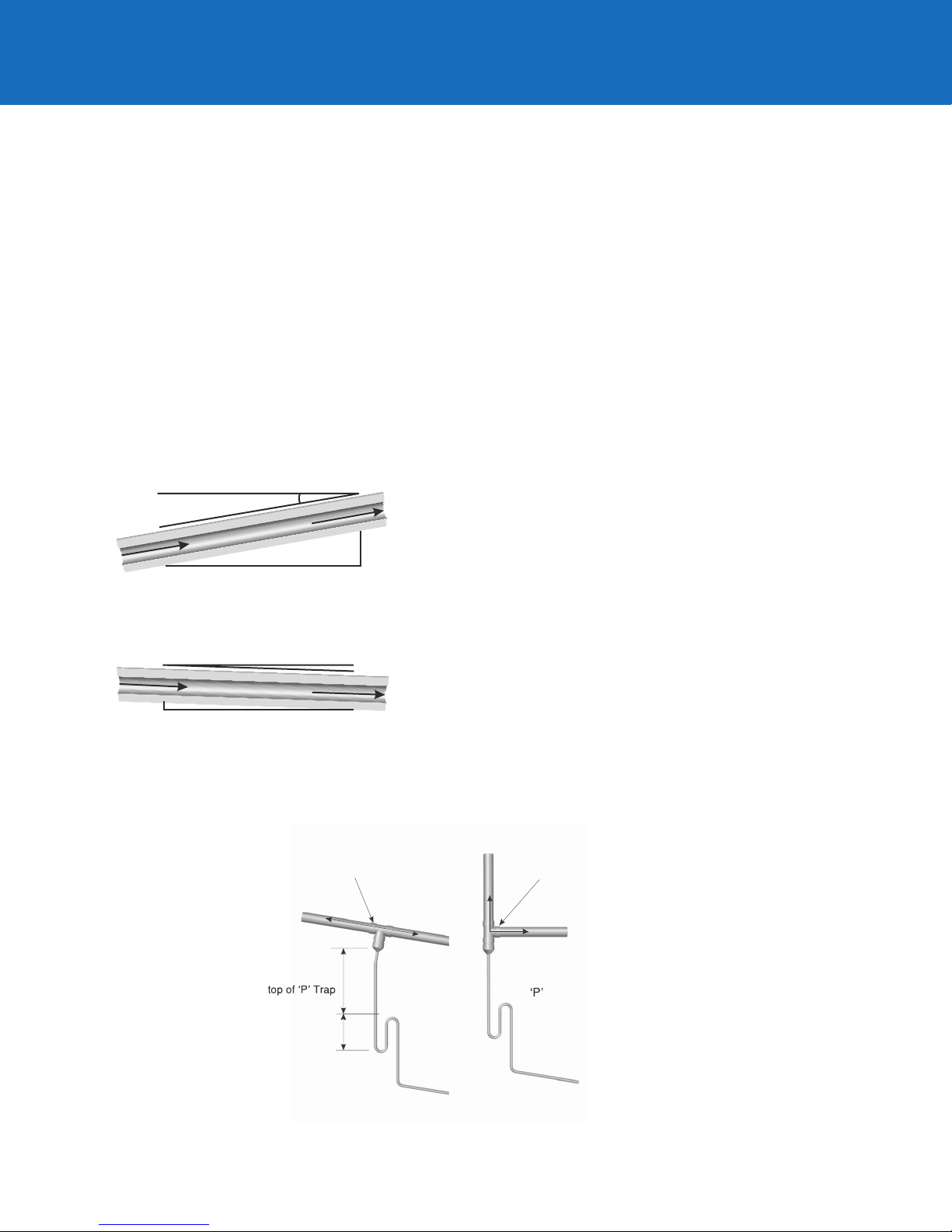
Atmospheric Steam Lines
12 in. (30 cm)
min drop to
P Trap
.
)
t
e
Tee is same size
as steam line
Use a full size tee, not a 90
degree elbow for vertical
to horizontal transitions.
Condensate drains must be sloped down.
Route to humidier ll cup if possible.
Install Requirements
1. Use ONLY copper, stainless steel tube, or Condair supplied steam
line for the atmospheric steam distribution line.
2. Follow recommended steam line materials, size, and length. See
tables to right.
3. Slope the steam lines, minimum 2” for every horizontal foot
against the ow of steam, ½” for every horizontal foot with the
ow of steam.
4. The rst vertical 12” of steam line o the top of the humidier
must not have any bends or turns.
5. Insulate copper or steel tube steam lines with 1.0 in. (2.5 cm) pipe
insulation.
6. Steam lines must not have any restrictions or condensate
trapping which could cause back pressure.
Minimal Slope (up)
10 Degrees
7. Tra p
Steam Direction
2 in.
(5 cm)
1 ft (30 cm)
Minimal Slope (down)
2 Degrees
Steam Direction
Steam Direction
0.5 in.
(12 mm)
1ft (30 cm)
condensate (Use full size ‘T’ for Traps) at all low points.
8. Install a condensate trap at every 15 foot / 4.5 meters of steam
line.
Traps Use:
- CONDAIR 0.375 in condensate hose
- 1/4 in Med-L copper tubing, or
- 0. 375 in stainless steel tubing
static pressur
min 8 in
(20 cm
plus duc
Page 7
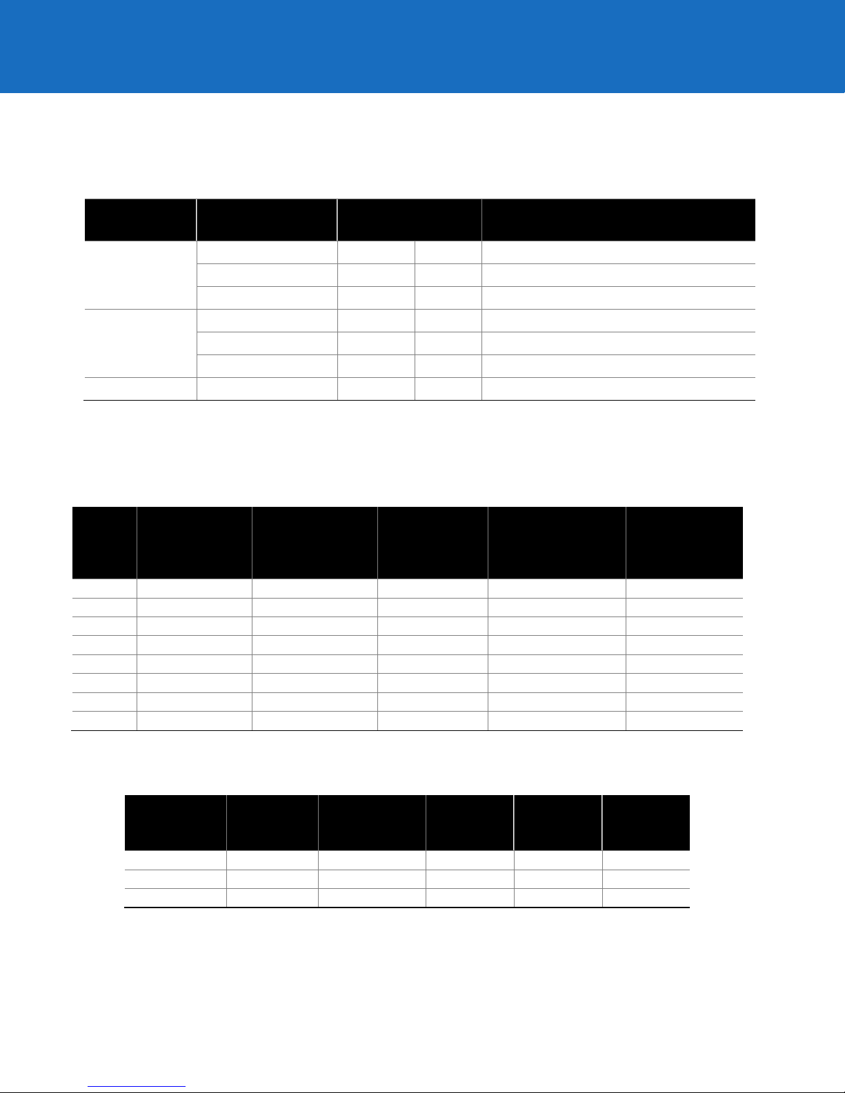
R ecommended Steam Line Material
100
100
(45)
1 1/2
(1 3/4)
90
(27)
0.11
(0.16)
10
(4.5)
250
250
(114) 3 (3)
180
(55)
0.16
(0.24)
28
(13)
375
375
(170) 4 (4)
180
(55)
0.22
(0.33)
39
(18)
525
525
(239) 4 (4)
220
(67)
0.22
(0.33)
48
(22)
1 ½ or 1 ¾
3.5
(1)
1.75
(0.5)
7
(2.1)
0.8
(2.4)
34
(10)
3
5
(1.5)
2.5
(0.75)
11
(3.3)
1.1
(3.1)
54
(16)
Steam Line
Material Lb/hr (kg/hr)
Steam Line Length
ft m Steam Line Description
0-100 (0 -45) 0-90 0-27 1 1/2 in. MED -L Tubing (1.625 in. OD)
Copper Tube
101 -250 (46 -113) 0-180 0-54 3 in. MED -L Tubing (3.125 in. OD)
251 -650 (114 -295) 0-260 0-79
**4 in. MED -L Tubing (4.125 in. OD)
0-100 (0 -45) 0-90 0-27 1.75 inch Tube x 0.065 inch thick wall
*Stainless
Steel Tube
101 -250 (46 -113) 0-180 0-54 3 inch Tube x 0.065 inch thick wall
251 -650 (114 -295) 0-260 0-79 **4 inch Tube x 0.065 inch thick wall
Condair Hose 31-100 (14 -45)** <15 <4.5
Note: * Use only stainless steel tube for reverse osmosis and deionized water applications.
** Use 2 x 4 in. steam lines for steam capacities higher than 750 lb/hr (307 kg/hr)
*** Use one steam hose per 100 lb/hr (45 kg/hr) of output.
***Part Number 1328820 (1 3/4”)
Maximum Recommended Length of Steam Line
Unit
Size
50 50 (23) 1 1/2 (1 3/4) 37 (11) 0.11 (0.16) 4 (2)
Steam Output
.
lb/hr
(kg/hr)
Steam Outlet
and Line Size .
Copper (SST)
Maximum
Length .
ft (m)
Possible Loss
.
lb/hr/ft
(kg/hr/m)
Possible Loss
at Max. length
lb/hr (kg/hr)
175 175 (80) 3 (3) 90 (27) 0.16 (0.24) 14 (6.5)
750 750 (341) 2 X 4 (4) 260 (79) 0.44 (0.66) 114 (52)
1050 1050 (477) 2 X 4 (4) 260 (79) 0.44 0.66) 114 (52)
Equivalent Length of Some Common Fittings
Tube
Diameter in.
4 8 (2.4) 4 (1.2) 15 (4.5) 1.6 (0.5) 80 (24)
90 Degree
Elbow
ft (m)
45 Degree
Elbow
ft (m)
Side
Outlet Tee
ft (m)
Gate Valve
ft (m)
Globe
Valve
ft (m)
Page 8
2575258-B
All information contained in this Quick Start Guide is for general
information purposes only. For complete Condair installation/
operation recommendations for your Condair equipment, please
refer to the installation manual for your specic system, accessories,
Printed in C anada
and components.
All electrical connections must be installed in accordance with local
and national electrical code requirements by a licensed electrician.
All water supply and drain line connections must be installed in
accordance with local plumbing codes by a licensed plumber.
Condair does not accept any liability for installations of humidity
equipment installed by unqualied personnel or the use of parts/
components/equipment that are not authorized or approved by
Condair.
USA 826 Proctor Avenue, Ogdensburg, NY 13669
Canada 2740 Fenton Road, Ottawa, Ontario K1T 3T7
1.866.667.8321
[email protected]
Member of th e Condair Group
 Loading...