

Page 1

2596061 EN 1905
IMPORTANT! Read and save these instructions. This manual to be left with the equipment.
INSTALLATION AND
OPERATION MANUAL
Adiabatic Humidification System
Condair MLP
US version
Humidication and Evaporative Cooling
Page 2

Thank you for choosing Condair
Installation date (DD/MM/YYYY):
Commissioning date (DD/MM/YYYY):
Site:
Model:
Serial number:
Contact
Condair Ltd.
2740 Fenton Road, Ottawa, Ontario K1T3T7
TEL: 1.866.667.8321, FAX: 613.822.7964
EMAIL: na.info@condair.com, WEBSITE: www.condair.com
Condair Inc.
2700 90th Street
Sturtevant, WI., USA 53177
TEL: 1.866.667.8321, FAX: 613.822.7964
EMAIL: na.info@condair.com, WEBSITE: www.condair.com
Proprietary Notice
This document and the information disclosed herein are proprietary data of Condair Ltd. Neither this document, nor
the information contained herein shall be reproduced, used, or disclosed to others without the written authorization
of Condair Ltd., except to the extent required for installation, operation or maintenance of the customer's equipment.
Liability Notice
Condair Ltd. does not accept any liability due to incorrect installation, maintenance or operation of the equipment,
or due to the use of parts/components/equipment that are not authorized by Condair Ltd.
Copyright Notice
© Condair Ltd., All rights reserved.
Technical modication rights reserved.
Page 3

Contents
1 Introduction 5
1.1 Before You Start! 5
1.2 General 5
2 For Your Safety 7
2.1 Safety 7
2.2 Health & Hygiene 8
3 Receiving and Storage 10
3.1 Inspection 10
3.2 Storage and Transportation 10
4 Site Planning 11
4.1 Prior to Starting 11
4.2 General Notes on Positioning 11
4.3 Experts on Site 12
5 Product overview 13
5.1 General description 13
5.2 Model Designation 14
5.3 MLP 100/300 Overview 16
5.4 MLP 500 Overview 17
5.5 MLP 2x800 overview 18
5.6 Principal installation diagram 19
5.7 Inlet water quality requirements 20
5.8 Optional equipment for MLP 20
5.9 MLP options list 21
5.10 MLP accessories list 22
6 Installation 23
6.1 General 23
6.2 Site Requirements and Sizing 24
6.3 Positioning the pump station 25
6.4 Water connection 26
6.5 Electrical installation 27
6.5.1 Power Supply Connection 28
7 Commissioning 29
7.1 Tools and materials for commissioning work 29
7.2 Inlet lter 30
7.3 Prepare for pump ush 31
7.4 Basic set-up of the controller 32
7.5 Pump ush procedure 37
3Contents
Page 4

8 Operation 38
8.1 Overview control unit 38
8.2 Equipment protection 39
8.3 Alarm messages 40
8.4 Controller menu 42
8.4.1 Alarms and user messages 43
8.4.2 Parameter change menu 44
8.4.3 Settings for section parameters 44
8.4.4 Pump 45
8.4.5 Conductivity monitoring, humidity logging and CIP (options) 46
8.5 Weekly inspection 47
9 Maintenance 48
9.1 Important notes on maintenance 48
9.2 Maintenance work 49
9.3 Preventive spare parts chart 50
9.4 Weekly check list 51
9.5 Troubleshooting 52
9.5.1 Malfunction with error indication 52
9.5.2 Resetting the error indication 53
9.5.3 Malfunction without error indication 54
10 Product data 55
11 Declaration of conformity 56
A Appendix 57
A.1 Siemens Scalence Router (option) 57
A.2 Optional Modbus TCP/IP 64
A.3 Setpoint 67
A.4 Temperature Sensor 69
A.5 Electrical Settings in the Humidity Regulator 70
A.6 Overview of calibration for conductivity sensors and converters (ampliers) 71
A.7 ML-system - Condair Ltd. 73
B Appendix 77
B.1 Installation Checklist 77
B.2 Commissioning Checklist 77
B.2.1 Pre-Start-Up Checklist 78
B.2.2 Performance Checklist 80
4 Contents
Page 5

1 Introduction
1.1 Before You Start!
Thank you for purchasing the Condair ML direct room high pressure adiabatic humidication system.
The Condair ML adiabatic humidier incorporates the latest technical advances and meets all recognized safety standards. Never-the-less, improper use of the Condair ML adiabatic humidier may result
in danger to the user or third parties, and/or damage to property.
To ensure safe, proper and economical operation of the Condair ML adiabatic humidier, observe and
comply with all information and safety instructions contained in this manual, as well as all relevant documentation of components of the installed humidication system.
If you have additional questions, contact your local Condair representative. They will be glad to assist you.
1.2 General
Limitations
The subject of this manual is the Condair ML direct room humidication pump stations and associated
equipment whether ancillary or supplementary. The various options and accessories may only be described
in-so-far as is necessary for proper installation and operation of the equipment. Additional information
on available options and accessories can be obtained in the instructions that are supplied with them.
This manual is restricted to the installation, operation, technical data and parts of the Condair ML direct
room humidication pump stations, and is intended for well trained personnel who are suitably qualied
for their respective tasks.
Symbols Used in This Manual
CAUTION!
The word "CAUTION" in conjunction with the general caution symbol is used to provide safety instructions that, if neglected, may cause damage and/or malfunction of the unit or damage to property.
WARNING!
The word "WARNING" in conjunction with the general warning symbol is used to provide safety instructions that, if neglected, may cause injury to personnel. Other specic warning symbols may also
be used in place of the general symbol.
Condair MLP
DANGER!
The word "DANGER" in conjunction with the general danger symbol is used to provide safety instructions that, if neglected, may cause severe injury to personnel or even death. Other specic danger
symbols may also be used in place of the general symbol.
XXXXXXX_EN_1905
5Introduction
Page 6

Other Related Publications
This manual is supplemented by other publications such as the ML Heads Installation Guide, which
are included in the delivery of the equipment. Where necessary, appropriate cross-references to these
publications have been added in this manual.
Storage of Manual
Keep this manual in a place where it is safe and readily accessible. If the equipment is moved to another
location, make sure that the manual is passed on to the new user.
If the manual is lost or misplaced, contact your Condair representative for a replacement copy.
Language Versions
This manual is also available in other languages – contact your Condair representative.
6 Introduction
XXXXXXX_EN_1905 Condair MLP
Page 7

2 For Your Safety
2.1 Safety
DANGER!
Always isolate all supplies to the system before commencing any maintenance or repair.
General
Every person who is tasked with the installation, operation or maintenance of the Condair ML adiabatic
humidier must read and understand this manual before performing any work. Knowing and understanding
the contents of the installation manual and the operation and maintenance manual is a basic requirement for protecting personnel against any kind of danger, preventing faulty operation, and operating the
unit safely and correctly.
All labels, signs and marking applied to the Condair ML adiabatic humidier must be observed and kept
in a readable state.
Personnel Qualications
All procedures described in this manual must only be performed by personnel who are adequately qualied, well trained and are authorized by the customer.
For safety and warranty reasons, any activity beyond the scope of this manual must only be performed
by qualied personnel authorized by Condair.
All personnel working with the Condair ML adiabatic humidier must be familiar with, and comply with
the appropriate regulations on workplace safety and prevention of accidents.
Intended Use
The Condair ML humidication heads are intended exclusively for adiabatic humidication and/or evaporative cooling using a RO water supplied (by others) Condair MLP high pressure pump station within
specied operating conditions (refer to the Condair MLP IOM for details). Any other type of application,
without the express written consent of Condair, is considered to be not conforming to its intended purpose, and may lead to dangerous operation and will void the warranty.
In order to operate the equipment in the intended manner all information contained in this manual, in
particular the safety instructions, must be observed closely.
Safe Operation
If it is suspected that safe operation has been compromised, the ML-System should immediately be shut
down and secured against accidental power-up.
Shut down the Condair ML Humidication System if:
Condair MLP
– Components are damaged, worn or very soiled
– Fans have stopped or are noisy
– Joints, pipes or hoses are leaking
– Unusual or very loud noise
No modications must be made on the ML-System without the manufacturer’s consent. All persons
working with the system must report to the owner if any alterations are detected.
Use only original accessories and spare parts available from your Condair representative.
XXXXXXX_EN_1905
7For Your Safety
Page 8

2.2 Health & Hygiene
DANGER!
Risk of infection or serious illness
The Condair ML System must be installed, operated and maintained in accordance with this manual.
Failure to do so could result in contamination that might cause Legionnaires’ disease, which can be fatal.
DANGER!
Risk of water contamination
To prevent water stagnation and microbial contamination, the systems power supply should be left
switched on. If the system is switched off for more than 48 hours, the pipework and system must be
disinfected as per the instructions, and a full risk assessment must be undertaken to ensure safe
operation.
Health Risks
Please observe the local health and safety codes, standards and technical guidance on the control of
Legionella in water systems.
The user is responsible for ensuring that the water system complies with local regulations, bye-laws and
guidelines (such as the HSE ACoP L8, VDI 6022, ISO 22000, HACCP or equivalent). If inadequately
maintained, water systems, of which any humidier is a part, can support the growth of microorganisms,
including the bacterium that causes Legionnaires’ disease.
Condair ML systems, products and components are produced according to the ISO 22000 standards,
which means that we have considered all aspects of this equipment to reduce the risk of Legionnaires’
disease and other similar conditions. However, the user is responsible for ensuring that the installation,
operation and maintenance work on the equipment is performed in a manner ensuring that the system
stays clean.
Any risks or hazards relating to the system, including during installation and maintenance, should be
identied by a competent health and safety representative who is responsible for introducing effective
control measures.
Water monitoring
The quality of water being used in the Condair ML Humidication System should be checked prior to
system commissioning and comply with the guidelines in the high pressure pump manual.
The Condair ML Humidication System must be monitored for hygiene as part of the maintenance program. Please refer to the maintenance section for further guidance.
8 For Your Safety
XXXXXXX_EN_1905 Condair MLP
Page 9

Guidelines for a Hygienic System
• Carry out a risk assessment of the water system using a competent person, and implement an appropriate monitoring and control program.
• Initiate procedures for changing lters, disinfection etc.
• Enter into a service contract that suits your company.
• Stop the system if polluted drinking water is found in your area.
• Avoid water temperatures between 77 °F (25°C) and 113 °F (45°C), which favour the growth of
Legionella.
• Do not stop the system unless it is faulty or leaking (avoid water stagnation).
• Refrain from closing nozzles or sections, unless there is leakage or a fault (avoid water stagnation).
• Disinfect the high-pressure system at least once a year and after every maintenance or repair. Always
carry out a complete system disinfection if it has been turned off for more than 48 hours.
• Have water samples taken and tested for harmful bacteria at least once a year.
• Conduct follow-up measurements until the system is clean if bacteria have been detected in the system.
Disinfection
Depending on the system hygiene, it is advised that preventative disinfection uid be added to the external RO water tank at an appropriate frequency, but at least once a year.
Condair Ltd. recommends using the disinfection uid HaloSpray or Sanosil S010 AG 5% (part number:
155404000) to the System via the high pressure pump, desired concentration 0.1%. HaloSpray or Sanosil
is safe, non-toxic and eco-friendly which provides a prophylactic, disinfection dose and is effective against
all types of microorganisms, including Legionella and E.coli.
Please read the pump manual for more information on disinfection.
If you are in any doubt about the suitability of water quality, please contact your Condair distributor who
will be happy to support you.
Condair MLP
XXXXXXX_EN_1905
9For Your Safety
Page 10

3 Receiving and Storage
3.1 Inspection
All Condair products are shipped F.O.B at the factory. All damage, breakage or loss claims are the responsibility of the shipping company. Upon receipt, remove the transit packaging and inspect the components
to ensure that no damage has occurred during transit. Inspect the goods as follows:
– Inspect the shipping boxes for damage. Report any shipping box damages to the shipping company
without delay.
– Check the goods against the packing slip to ensure that all items have been delivered. Report any
shortages to your Condair representative within 48 hours of receipt of the goods. Condair does not
assume responsibilities for any shortages beyond this period.
– Unpack the parts/components and check for any damage. If parts/components are damaged, notify
the shipping company immediately.
– Verify the model type on the specication label to ensure that it is suitable for your installation.
3.2 Storage and Transportation
Storage
Store the Condair ML adiabatic humidier in its original packaging inside a protected area that meets the
following requirements until it is installed. These requirements also apply if the unit needs to be stored
for an extended period of time. If put into storage prior to use, the components must be covered and
protected from physical damage, dust, frost and rain. Avoid below freezing temperatures as this can
degrade certain wet parts and components.
For storage Condair recommends:
– Room temperature: 41 to 104°F (5 to 40°C)
– Room humidity: 10 to 75% RH
Transportation
For optimum protection always transport the unit and components in their original packaging, and use
appropriate lifting/transporting devices.
Lifting or handling must only be carried out by trained and qualied personnel. Ensure that the lifting
operation has been properly planned and risk-assessed, and that all equipment has been checked by
a skilled and competent health and safety representative.
The customer is responsible for ensuring that operators are trained in handling heavy goods, and to
enforce the relevant lifting regulations. Refer to the weights and measures section for system weight.
Packaging
It is recommended that the components be kept in its transit packaging for as long as possible prior to
installation.
Keep the original packaging of the unit/components for later use. If the packaging needs to be disposed
of, observe local regulations on waste disposal. Recycle packaging where possible.
Disposal
You must observe local laws and regulations when disposing of your Condair ML system at the end of
its working life.
10 Receiving and Storage
XXXXXXX_EN_1905 Condair MLP
Page 11

4 Site Planning
4.1 Prior to Starting
The basic principles for planning described below are theoretical ones. In practice, the necessary humidication capacity is inuenced by parameters that cannot be covered by this documentation. For
this reason, the values that were determined in theory have to be complemented by practical values or
corrected in many cases. Condair’s technical service team will be pleased to assist you.
Notes on the planning of direct room air humidication systems in one or more zones.
Proceed as follows when selecting and/or dimensioning the air humidication system:
• Determine the volume of the room and the air changes
• Determine the set points (temperature and humidity/relative humidity)
• Determine the humidication areas
• Calculate the maximum humidication capacity
• Dene the device requirements
• Determine the placement of zone valves and hygrostats
4.2 General Notes on Positioning
The positioning of a system is always determined during planning and noted in the system documents.
Prior to mounting the ML Direct Room Humidication heads, ensure that all hose layouts, distances
between heads and atomization clearances have been considered and adhered to, as per the ML Heads
Installation Guide.
The recommended hose layouts, distances between humidication heads and atomization clearances,
are shown in the ML Heads Installation Guide. Consult local and national installation regulations. Condair
does not accept responsibility for violations of the installation codes.
The following general positioning notes, however, have to be read and complied with in any case:
• Make sure that the construction (rafter, beam, wall, pillar, ceiling construction, etc.) on which the
devices and/or system components will be mounted disposes of a sufcient load-carrying capacity
and is suitable for xing
• Position the Condair ML Direct Room Heads in such a way to enable the atomized mist to spread
freely. When the mist is prevented from spreading by obstacles (e.g. ceilings, beams, ventilation
ducts, airow, machinery, etc.), turbulences can build up and condensation may occur as a result.
• ML Heads Installation Guide shows the recommended clearances, of the expansion of the atomization stream, and the clearances that have to be maintained. These are ideal and recommended
maximum capacities using ML nozzles. Different weather, climate and indoor conditions can alter
the spread and distance of the mist.
Condair MLP
• As shown in ML Heads Installation Guide, when the nozzles and humidication heads are placed
one opposite the other, make sure that a minimum distances are adhered to. This will avoid the
streams to condensate each other.
• Pay close attention to the airow of the room. Do not install humidication heads or nozzles in the
immediate vicinity of a supply, return or exhaust system or of a cold-air inlet.
XXXXXXX_EN_1905
11Site Planning
Page 12

• Do not point humidication heads or their nozzles at cold parts of a building, e.g. outside walls,
windows, etc. (risk of condensation).
• Insulate cold-water pipes in the area of the atomizing stream (risk of condensation).
• The evaporation process absorbs heat from the ambient air. For this reason, make sure that the
atomized stream is not directed on persons or on places directly above workplaces.
• In order to guarantee optimum humidication, ensure that the atomizers are sensibly distributed in
the room.
• The system components have to be mounted in such a way to provide enough space for operation
and maintenance.
Please contact Condair’s Technical Service Team in case you have questions on positioning and clearances.
4.3 Experts on Site
Condair has expert technicians employed by Condair who can provide:
• Pre-site analysis
• Positioning and site assistance or recommendations
• Installation support
• Start-up and commissioning
• Bacteriological troubleshooting on site *
• Cleaning and disinfecting
• Preventive maintenance
• Repair and fault nding
• Training and guidance
*Condair uses an industry leading method for measuring bacterial activity in the water; the approved
and patented BactiQuant test. This, unique to Condair, eld test takes water samples from critical project
locations. Thereafter, the bacteriological quality of the water can be read within 30 minutes, and the
system can be disinfected if necessary.
Condair follows the guidelines in VDI 6022 for colony forming units (CFU) counts in humidiers. The
CFU count in the humidication water must not exceed 150 CFU/ml, corresponding to a maximum BQ
value of 52. Please contact your local Condair representative for further information about our services.
12 Site Planning
XXXXXXX_EN_1905 Condair MLP
Page 13

5 Product overview
5.1 General description
The MLP series is a high-pressure pump station for direct room humidication it’s developed by Condair
Group AG with focus on reliable and hygienic humidication solutions.
The MLP comes in ve basic models, MLP 100, 300, 500, 800 and 1000. The number indicates
the maximum continuous water outlet (high-pressure) at 943 psi (65 bar). If a larger capacity than
264 gal/hr (1000 l/h) is needed the MLP’s is made in versions with double or triple high pressure pumps
called e.g. MLP 2x800 or MLP 3x1000.
Important:
All components exposed to water are made of corrosion-resistant material. All hoses are steel-reinforced
and drinking water-approved.
The high-pressure pump is directly mounted on the electric motor. Power is supplied to the 3-phase
asynchronous motor via a magnet-operated protective motor switch. The high-pressure pump is protected against dry running by a pressure switch in the inlet manifold. A temperature sensor monitors the
temperature inside the pump and protects it from overheating.
The control unit consists of a touch display and a PLC mounted in the IP 65-rated electrical cabinet as
well as a power board for control of the high-pressure pump and connection terminals for power supply
(208...480 V/3N~/50-60 Hz).
From the touch screen, the operator can easily change humidity set point in each section, adjust alarm
limits and view hour counters, logged alarms, trend curves, etc.
The pump station is electrically wired at the factory. At the installation site, main power supply, humidity
signal, external safety chain, step valves and additional options must be electrically connected to the
control unit.
Condair MLP
XXXXXXX_EN_1905
13Product overview
Page 14

5.2 Model Designation
The specication label on the side of the Condair ML adiabatic humidier shows its model number, year
made, serial number, power supply and ratings. The breakdown of the model number is shown in Figure 1.
Product series:
Humidication Load (liters/hour):
100
300
500
800
Voltage and phase:
208V/3~
400V/3~
480V/3~
Figure 1: Model designation
Condair MLP 300 480V/3~
Electrical Schematics and Wiring Diagrams
A copy of the electrical schematics and wiring diagrams can be found on the inside panel of the control
panel.
The rating plate is placed in the upper left corner on the side of the control unit (when facing the front).
Figure 2: Rating plate
14 Product overview
XXXXXXX_EN_1905 Condair MLP
Page 15

A label with the internal order number and electrical schematic diagram number is placed on the inside
of the left-hand cabinet hatch (when facing the front) on the control unit.
Figure 3: Label with the internal order number and electrical schematic diagram number
Condair MLP
XXXXXXX_EN_1905
15Product overview
Page 16

5.3 MLP 100/300 Overview
Figure 4: MLP 100/300 Overview
Figure 5: Hydraulic diagram MLP 100/300
F Filter 10", 1 µm
FR Water meter
G1 Pressure gauge, 0-145 psi (0-10 bar)
G2 Pressure gauge, 0-145 psi (0-10 bar)
G3 Pressure gauge,
high-pressure 0-2321 psi (0-160 bar)
K1 Check valve
K2 Check valve
M1 Motor, high pressure pump
MV1 ON/OFF valve 1/2" 0-145 psi (0-10 bar)
P1 PAH high-pressure pump 1015 psi (70 bar)
PS Pressure switch
PT Pressure transmitter (Option)
R Pressure reduction
T Thermostat
UV UV system
V1 Test water tap
Table 1: Legend MLP 100/300 Overview
16 Product overview
XXXXXXX_EN_1905 Condair MLP
Page 17

5.4 MLP 500 Overview
Figure 6: MLP 500 Overview
Figure 7: Hydraulic diagram MLP 500
F
FR
G1
G2
G3
K1
K2
M1
Filter 10", 1 µm
Water meter
Pressure gauge, 0-145 psi (0-10 bar)
Pressure gauge, 0-145 psi (0-10 bar)
Pressure gauge,
high-pressure 0-2321 psi (0-160 bar)
Check valve
Check valve
Motor, high pressure pump
MV1
P1
PS
PT
R
T
UV
V1
ON/OFF valve 1/2" 0-145 psi (0-10 bar)
PAH high-pressure pump 1015 psi (70 bar)
Pressure switch
Pressure transmitter (Option)
Pressure reduction
Thermostat
UV system
Test water tap
Condair MLP
Table 2: Legend MLP 500 Overview
XXXXXXX_EN_1905
17Product overview
Page 18

5.5 MLP 2x800 overview
Figure 8: MLP 2x800 Overview
Figure 9: Hydraulic diagram MLP 2x800
F1 Filter 10", 1 µm
FR1 Water meter
G1 Pressure gauge, 0-145 psi (0-10 bar)
G2 Pressure gauge, 0-145 psi (0-10 bar)
G3 Pressure gauge,
high-pressure 0-2321 psi (0-160 bar)
K1+K2 Check valve
Table 3: Legend MLP 2x800 Overview
K3+K4 Check valve
P1+P2 PAH high-pressure pump 1015 psi (70 bar)
PS Pressure switch
R1+R2 Pressure reduction
T1+T2 Thermostat
UV1 UV system
V1 Test water tap
18 Product overview
XXXXXXX_EN_1905 Condair MLP
Page 19

5.6 Principal installation diagram
sensor
valve
sensor
valve
sensor
valve
modules
Reverse
Osmosis
Ion exchange
Power
Supply
ML Princess
Solenoid
Humididity
Humidication zone
Power
Supply
ML Solo modules
Humidication zone
Drain
Humididity
Solenoid
ML Flex Line system
Humidication zone
Drain
Humididity
Solenoid
Drain
Drain
filtration
treatment:
ML Pump station and water treatment
Power
Supply
treatment:
Optionalwater
Optional water
Water
Supply
Safety pre-
Carbonfilter
Carbon lter
Reverse osmosis
Softening
Softening
Safety preltration
Figure 10: Principal installation diagram
Condair MLP
XXXXXXX_EN_1905
19Product overview
Page 20
5.7 Inlet water quality requirements
The quality of water being used in the MLP system should be checked prior to system commissioning.
Condair A/S recommends that the MLP system be connected to a RO or DI mains water supply.
Table 4: Inlet water quality requirements
Water supply Reverse osmosis or demineralized water
Conductivity 5-50 µS/cm
TDS max 35 ppm
KMnO4 max 10 ppm
NTU max 1.0
Temperature max 59°F (15°C)
Fe max 0.2 ppm
Mn max 0.05 ppm
Max hardness max 1º dH
free chlorine max 0.1 ppm
5.8 Optional equipment for MLP
Choosing the right water treatment is essential for successful humidication. In the ML-System programme,
there is a large variety of water treatment and optional equipment to choose from. The ML-System is
designed to be customised to meet the specications, be it essential water treatment or features. It is
possible to combine ML Systems, water treatment and optional equipment in numerous combinations
and it is thus impossible to describe all of them here. In the following, the most commonly used ancillary
and optional equipment for the MLP system is listed.
Optional and ancillary equipment can be divided into the three following main groups:
MLP options: Added features which are intergraded into the controller of the MLP or placed on its frame,
e.g. conductivity and hardness alarm, BAS integration, ultra-pure water (mixed bed), CIP system, CO
adding, damping water outlet, holding tanks (RTN). Options cannot be retrotted and must therefore be
listed when ordering
Water treatment: Stand-alone systems for improving the water quality in order to meet the inlet water
quality requirements for the MLP, e.g. booster pump, non-return valve, silt/pre-lter, carbon lter and
softener. See separate Water treatment / RO manual for further information.
High-pressure building installation: Added features and optional equipment – e.g. fan speed controller,
ow monitor, temperature read-out. Options for the high-pressure building installation will be described
in the I/O manual for the high-pressure building installation. See separate High-pressure equipment
manual for further information.
2
20 Product overview
XXXXXXX_EN_1905 Condair MLP
Page 21

5.9 MLP options list
Options cannot be retrotted and must therefore be listed in connection with order placement.
Table 5: MLP options list
Fan control (Prepare of the control board)
Fan control box (1-4 zones) Start/stop fans in each zone between humidication cycles.
Overheating protection of the
high-pressure pump (ow/
temp-dependent)
PLC webserver access Access to the PLC's homepage from a standard browser.
Humidity logger Logs the humidity in each zone every 15 minutes (1 year back).
BAS/BMS integration Modbus
TCP/IP
Backup high-pressure pump The pump station is tted with an extra high-pressure pump for
Status relay Potential-free relays for (ready, running, warning, error).
Pulse generator for water meter The water meter is equipped with a pulse emitter which can be
Prepares the control board with terminals I/O for connecting a
fan control box.
Only possible if the control board has been prepared for the
accessory.
Dumps excess water via a solenoid valve if the temperature or
ow through the pump comes outside the permissible limit.
Displays the operating status and humidity for each zone.
Data is stored in a .csv comma-separated values le, which can
be accessed on a SD card or the PLC's webserver.
Displays the operating humidity and alarm status of the system
via a TPC/IP protocol.
redundancy, automatic changeover.
linked to tele-reading systems, the PLC and to M-Bus networks.
Condair MLP
XXXXXXX_EN_1905
21Product overview
Page 22

5.10 MLP accessories list
Accessories can be retrotted.
Table 6: MLP accessories list
Pulse generator for water meter,
retrot kit
ML control box for induct system ML satellite unit for connecting and controlling an induct system
Satellite box (4 zones) Ads 4 additional zones (humidity I/O and zone valve terminals) to
Satellite box (8 zones) Ads 8 additional zones (humidity I/O and zone valve terminals) to
Humidity logger retrot kit Logs the humidity in each zone every 15th minute one year
Alarm lamp Alarm ash which can be placed up to 328 ft (100 m) from the
Modbus TCP/IP Gateway IP
translator
Remote alarm SMS Sends a SMS via a prepay SIM-card if the system goes in alarm
Remote alarm email Sends an email if an alarm is triggered in the system and when
BAS/BMS integration Modbus
TCP/IP, retrot kit
The water meter is equipped with a pulse emitter which can be
linked to tele-reading systems, the PLC and to M-Bus networks.
from an MLP or an MLP pump station.
an existing ML-System.
an existing ML-System.
back. Data is stored in a .csv comma-separated values le.
pump, connects to an alarm output.
Easy setup op Modbus TCP/IP communication to BAS as IP addresses can be chosen by the costumer on site.
and when the alarm is cancelled.
the alarm is cancelled. Up to 25 recipients.
Displays the operating humidity and alarm status of the system
via a TPC/IP protocol.
22 Product overview
XXXXXXX_EN_1905 Condair MLP
Page 23

6 Installation
6.1 General
Strictly observe and perform all installation tasks including the mounting of the unit and connection of the
water and power supplies as described in this manual. Observe and comply with all local and national
codes dealing with water and electrical installations.
Condair does not accept any liability for installation of humidication equipment by unqualied personnel,
or the use of equipment/parts that are not authorized by Condair.
Personnel Qualications
All installation work must be performed only by persons familiar with the ML-System pump station and
sufciently qualied for such work. All work on electric installations must only be performed by adequately
qualied electricians.
Safety
The pump station and any control units may only be connected to the mains after all installation work
has been completed. All statements relating to correct positioning and installation must be followed and
complied with. When installing components of the MLP, use the materials and hoses supplied with the
unit. In case of doubt, please contact your Condair supplier.
Observe the following safety precautions:
WARNING!
Risk of injury and risk of damage to equipment
Do not retighten/unscrew hoses while the system is pressurized!
CAUTION!
Risk of breeding ground for bacteria
Do not use oil, grease, glue, Teon, silicon, O-ring lubrication, etc. when assembling pipes or
hose connections.
All of the above products can act as food for bacteria and therefore may pose a health risks.
Prevention: Wash your hands before or wear clean gloves while assembling parts in direct
contact with water. Keep dust covers on pipes and hoses until just before assembly. Only approved lubricant is dish soap
CAUTION!
Do not fasten the pump station or hoses/pipes to vibrating installations.
Condair MLP
CAUTION!
Risk of damage to internal components from electrostatic discharge (ESD)
The electronic components inside the humidier are sensitive to electrostatic discharge (ESD).
Prevention: Take appropriate and special measures to protect the electronic components inside the
unit against damage caused by ESD.
XXXXXXX_EN_1905
23Installation
Page 24

WARNING!
Heavy object - risk of injury!
The pump station or pump skid are extremely heavy. Smaller models can weigh 275 lb (125 kg)
while the bigger units can weigh in excess of 550 lb (250 kg).
Prevention: Always use appropriate lifting device(s), and proper assistance, safety equipment, har-
ness prior to lifting or moving any Condair ML equipment.
Recommended Tools
Condair recommends the following tools for unpacking, measuring, connecting and tightening all things
regarding installation.
• Screwdriver set
• Spirit level
• Polygrip pliers
• Wire cutters
• Spanner set
• Tape measure
• Marker
• Box cutter
6.2 Site Requirements and Sizing
Please observe the following regarding positioning and installation:
• The pump station must be installed only in a location with a drain in the oor.
• The site must be freely accessible with sufcient space for convenient operation and maintenance.
• Minimum recommended clearance and free space around pump station: 20 inches (0.5 m) side to
side, and 32 inches (0.8 m) front and back.
• The pump station is designed for operation in a frost-free and dry environment, never outdoors.
• Do not install the pump station in exposed locations or locations with heavy dust loads.
• The pump station is designed for installation on a load-bearing oor.
24 Installation
XXXXXXX_EN_1905 Condair MLP
Page 25

6.3 Positioning the pump station
Please observe the following on positioning and installation:
• The pump station must be installed only in a location with a drain in the oor.
• The site must be freely accessible with sufcient space for convenient operation and maintenance
(min. free space around pump station: laterally 19.7" (0.5 m), 31.5" (0.8 m) front / back).
• The pump station is designed for operation in a frost-free and dry environment, never outdoors.
• Do not install the pump station in exposed locations or locations with heavy dust loads.
• The pump station is designed for installation on a load-bearing oor.
Before installing the MLP it is important to consider placement of additional water treatment equipment
in the room ( e.g. Carbon lter, softener, RO). Please note that the combination/size of water treatment
systems will vary from one installation to the next due as a result of water quality and regulatory
requirements in the given location.
Start by examining the types of water treatment systems to be installed and read their installation
instructions as regards location and any requirements for supply and drainage.
Mark the location of the different systems in the room and note any missing supply or drains for the
systems. Make sure you have the necessary xing equipment available: cable ties, cable trays, screws
and wall anchors.
Adjust the screws under each leg on the
frame so that the pump station and the
RO tank (if relevant) can be levelled. Use
a bubble level to ensure that the pump
station is perfectly level.
Figure 11: Adjusting the pump station
Condair MLP
XXXXXXX_EN_1905
25Installation
Page 26

6.4 Water connection
WARNING!
Do not open and ll hoses, pumps, lters or tanks with water if the system is not to be started
immediately after installation (48 hours). Stagnant water acts as a breeding ground for potentially
dangerous micro-organisms.
Before connecting the MLP to the water supply it must be ensured that the incoming water is as clean
as possible. These is done by running a hose from the supply to the drain and open the shut-off valve
completely. Let the water run to drain for at least ten minutes. Shut off the water again and connect MLP to
the water supply with the supplied hose (3/4"/59.1" (3/4"/1.5 m)). Condair recommends that the in coming
water is tested for bacterial contamination please contact Condair for further information on the subject.
1: ¾" RG male inlet connection
2: Gasket
3: Steel braided hose
26 Installation
Figure 12: Water connection
XXXXXXX_EN_1905 Condair MLP
Page 27

6.5 Electrical installation
DANGER!
Danger of electric shock!
Installations and electrical connection must only be done by trained technicians and according
to local standards
High voltages, danger of electric shock! Touching live parts may cause severe injury or death.
All connections must be made according to the electrical documentation which is found inside the control
unit of the electrical cabinet / main box.
Notes on electrical installation
– Installation must be carried out according to local rules and regulations
– The electrical installation (power supply, humidity control) must be carried out according to the wir-
ing diagram supplied with the unit and the applicable local regulations. All information given in the
wiring diagrams must be followed and observed.
– All cables must be run into the control unit via the cable openings and the use of cable glands.
– Make sure the cables do not rub against vibrating parts.
– The supply voltage must comply with the voltage in the wiring diagram.
– Study the system set-up part to get an overview.
– The pump station comes with a 3 m rubber coated power cable.
– Power consumption and size of pre-fuse can be found chapter with product data
Condair MLP
XXXXXXX_EN_1905
27Installation
Page 28

6.5.1 Power Supply Connection
• Make sure that electrical supply corresponds to the specications on the humidication system rating plate.
• Unlock the control panel enclosure door with the provided panel key.
• Insert the power supply cable through a suitable free cable gland and lead the cable to the eld
terminal block, as shown on the picture of the enclosure below.
• Follow the appropriate electrical wiring diagram for the actual humidication system and connect the
power supply leads to the eld terminal block accordingly.
28 Installation
XXXXXXX_EN_1905 Condair MLP
Page 29

7 Commissioning
WARNING!
The system start-up must be carried out or monitored by persons approved and trained by
Condair. Errors in the start-up phase may ultimately result in illness, injury and death of humans..
CAUTION!
When tting water lters, RO membranes, hoses and other components in direct contact with
water please, wear sterile gloves or touch only the packing paper to keep the lter bacteria-free.
Remember to wash your hands!
CAUTION!
Commissioning of the pump should be the last thing performed at an installation site. When
the pump has run with water and the preservation uid (windscreen wash) has been ushed
out, it should always be kept on (summer and winter) in order to keep the system hygienically
clean by allowing it to run its automatic ushing and UV routine.
7.1 Tools and materials for commissioning work
– Screwdriver set (remember small screwdriver for terminals)
– Polygrip pliers
– Spanner set
– Conductivity Meter
– BQ water analyses set ML part: 155600010
– Multi-meter (Volt, Amp)
Condair MLP
XXXXXXX_EN_1905
29Commissioning
Page 30

7.2 Inlet lter
Insert lter:
• Unscrew the lter housing [1] using a lter
wrench.
• Insert the lter [2], and make sure that it is
centered on the guide knob at the bottom of
the lter housing.
• Tighten the lter as much as possible by hand
and then use the lter wrench to tighten approx.
1/4 turn.
• Slowly open the water supply
• If the lter housing is hard to tighten or leaks,
unscrew it and check that the lter is centered,
the O-ring is undamaged and the sealing surface is smooth and free of dirt.
Figure 13: Inlet lter housing and lter
Figure 14: Air-vent screw, inlet lter
Note: Do not touch the lter with your bare hands
(slide it out of the packing directly into the lter
housing).
Airing lter:
• Slowly open the water supply (tap) to the MLP
• Bleed the lter by loosening the air-vent screw
[1] on the lter top until water leaks continuously.
• Retighten the air-vent screw.
30 Commissioning
XXXXXXX_EN_1905 Condair MLP
Page 31

7.3 Prepare for pump ush
CAUTION!
The rst time a new pump and/or RO membrane is to be used, it is important to ush out any
preservation uids so that they do not end up in the high-pressure system.
• Remove plugs and strips from the highpressure
hose and lead it to a drain or a bucket.
Figure 15: Flushing the pump
Before the pump is started for the rst time, the controller must be set up.
Condair MLP
XXXXXXX_EN_1905
31Commissioning
Page 32
7.4 Basic set-up of the controller
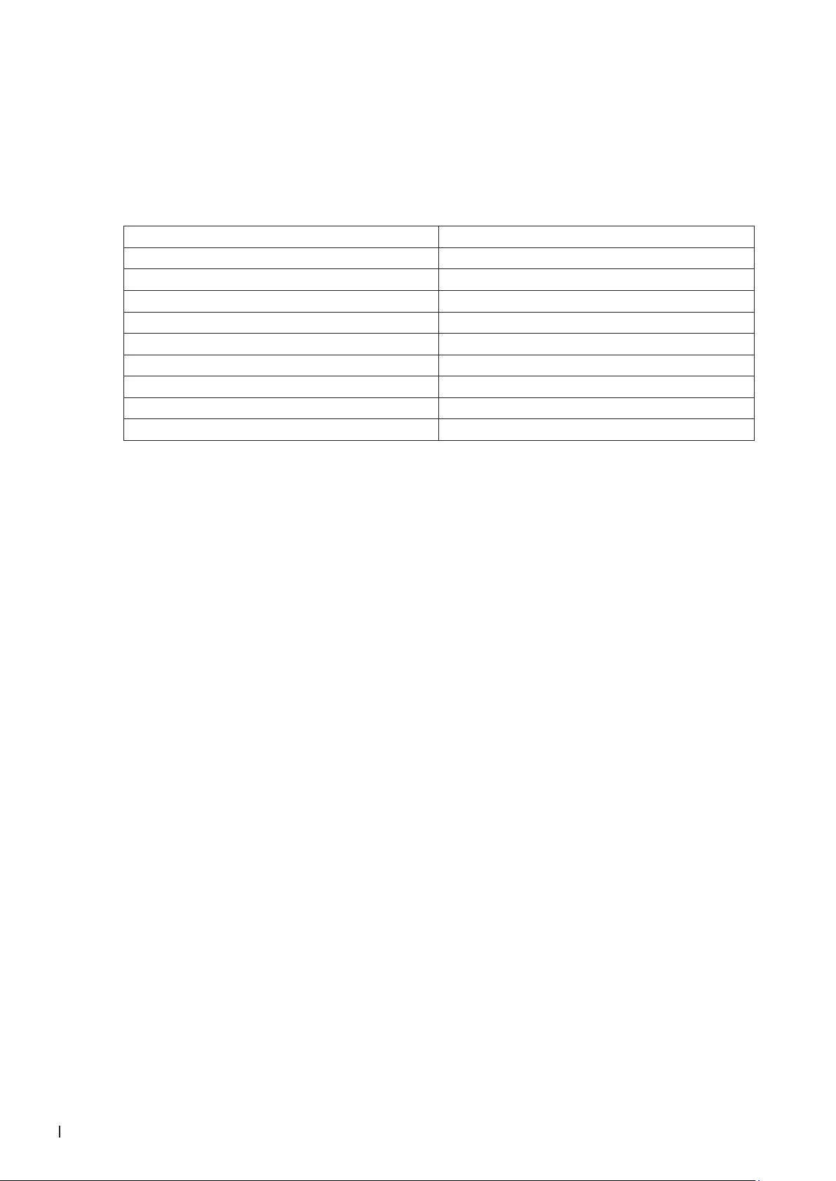
Figure 16: Control unit
1: Touch Screen (D2)
2: Humidication On/Off (S1)
3: Reset/Start (S2/P1)
4: Keyhole, open cabinet
5: Main power switch (S3)
• Put S1 in OFF position
• Start the controller by turning the power switch
S3 in ON position
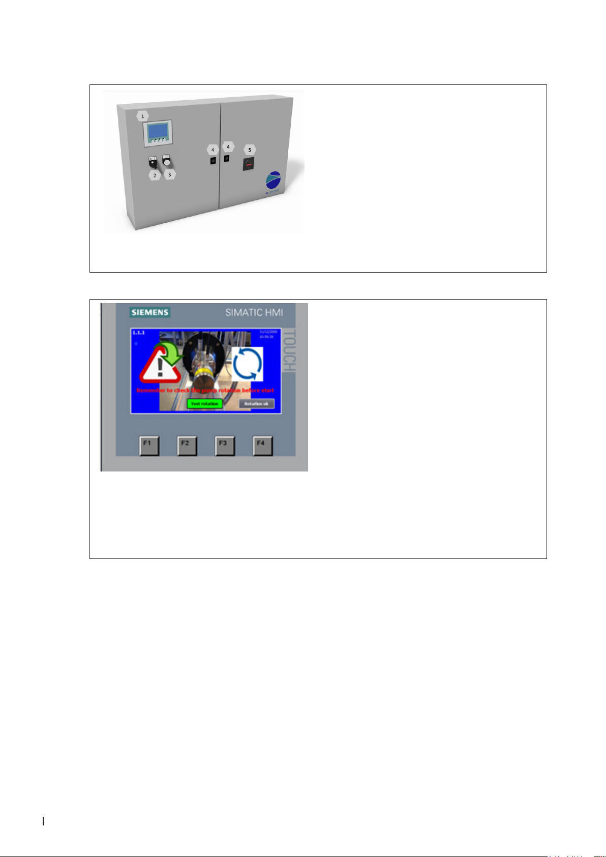
• The display lights up the start center → ►START
1.1.1
Every time the system is switched on after a power
break, you will see a screen that tells you to control
the pump rotation.
Verify that the pump rotation is correct.
A push on the Test rotation starts the high-pressure
pump for 5 seconds, so that the rotation can be
observed according to the arrows on the pump.
When the rotation control has passed it is possible
(by customer’s responsibility) to skip this screen
in the future (It can be deselected in screen 1.6).
Upon completion of rotation control, press Rotation
ok.
A technician pin will be required; 197
32 Commissioning
XXXXXXX_EN_1905 Condair MLP
Page 33

1.1
Select language by pressing the ag.
Select the units to use in the screens.
• Litre/hour
• Lb/hour
• Celsius
• Fahrenheit
Press the right arrow (F4) to continue.
1.0
The Basic setup page provides access to pages
and selectable functions:
1.1-Choice of language
1.2-Calibration of screen
1.3-Set time and date
1.4-Selection of active sections
1.5-Selection of names for the sections
1.6-General selections (settings)
1.7-Membrane ush
1.8- Version and change passwords (factory
settings)
1.9-ML-System (factory settings)
Once you have made your selection(s), press Home
(F1) to continue.
1.2
Calibrate Screen: Adjusts the viewing angle, so
you can stand upright and operate the screen.
When calibrating, do not lean forward in order to
get a better view. You will not get the desired effect.
Condair MLP
XXXXXXX_EN_1905
33Commissioning
Page 34
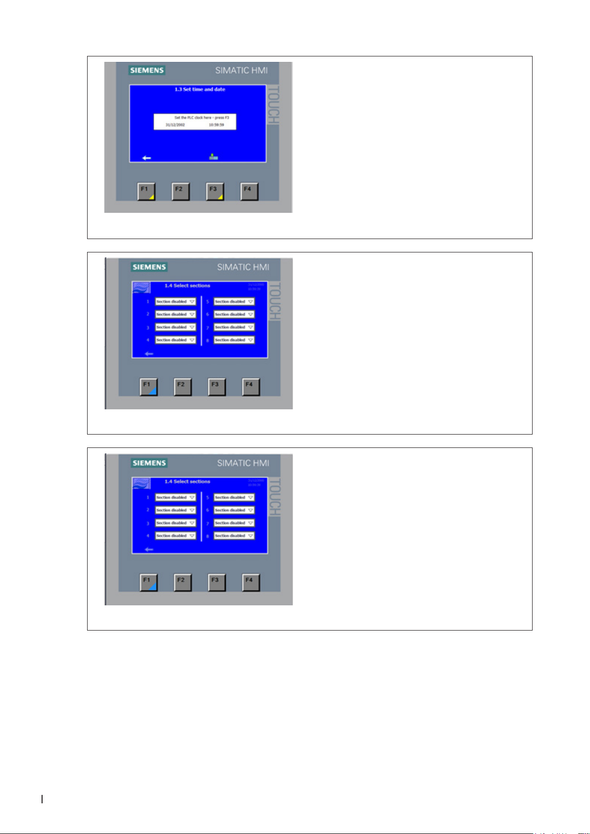
1.3
Time/date can be set (stored in the screen only).
Note: Remember to press F3 to set the PLC clock
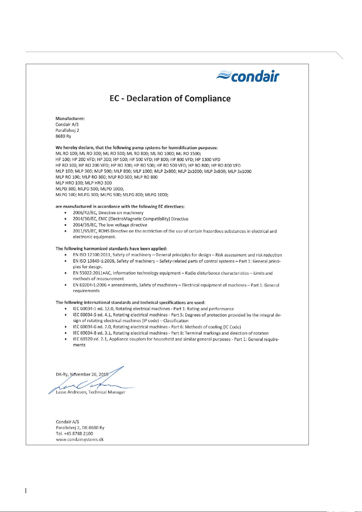
1.4
Select which section (zones) is active.
A section is dened as a humidity sensor and a
valve set connected to the controller
• Section disabled
• Section enabled
1.5
Selection of user-dened section names.
You can use up to 8 characters to dene each
section.
Default is 1-2-3…11-12
34 Commissioning
XXXXXXX_EN_1905 Condair MLP
Page 35

1.6
General selection between options and setups for
the general pump station. Please note that some of
the options require hardware that has to be ordered
together with the pump.
Master pin will be required; 8599
Standard setting is the top choice in the drop-down
menus.
Here also shown in bold:
• No CIP function
• CIP function
• No fan control
• Aut fan control
• Constant fan control
• No EC monitoring
• EC monitoring
• EC monitoring +RV/CO2
• EC monitoring +MB+CO2
• No pressostat 3
• Pressostat 3
• Aut reset disabled (inlet water low pressure)
• Aut reset enabled (inlet water low pressure)
• 1 section – valve set
• 1 section – no valve set
• Humidity controlled (20-80% RH)
• Direct controlled (0-10 V)
• % controlled (0-100%
• No Logging
• Logging selected
• Rotation check enabled (1.1.1)
• Rotation check disabled (1.1.1)
Condair MLP
XXXXXXX_EN_1905
35Commissioning
Page 36

1.7
Select MLP size and select 1-4 or 1-8 sections.
This selection is pre-set from factory according to
the controller hardware.
Changing password is only possible with the master
password.
36 Commissioning
XXXXXXX_EN_1905 Condair MLP
Page 37

7.5 Pump ush procedure
Venting and ushing the high-pressure pump:
Force the HP pump to run by adjusting the set point
in a section to 75%.
Let the HP pump ush for 10 minutes.
Turn S1 (on/off switch) to off position, and connect
the HP discharge hose to the high-pressure
manifold.
Note: It is important to use two wrenches, otherwise
there is a danger of the glue breaks and highpressure manifold leaks.
Figure 17: Connecting HP discharge hose
Leave the main switch turned on and the S1 (on/off switch) in off position. This way the system will perform a ush routine that together with the UV lamp will help keeping the system clean.
Condair MLP
XXXXXXX_EN_1905
37Commissioning
Page 38

8 Operation
Every person operating the MLP's controller must have read and understood this manual.
Knowing and understanding the contents of the manuals is a basic requirement for protecting the personnel against any kind of danger, to prevent faulty operation and to operate the unit safely and correctly.
All safety notes in the installation and operation manual for the MLP must be observed and adhered to.
All work described in this controller manual may only be carried out by properly trained personnel which
is authorised by the customer.
If you have questions after reading this documentation, please contact your Condair representative who
will be happy to assist you.
8.1 Overview control unit
1: Touch Screen (D2)
2: Humidication On/Off (S1)
3: Reset/Start (S2/P1)
4: Keyhole, open cabinet
5: Main power switch (S3)
Figure 18: Control unit
38 Operation
XXXXXXX_EN_1905 Condair MLP
Page 39

8.2 Equipment protection
Pressure switch (inlet water)
The MLP has a pressure switch which monitors the inlet water pressure.
If the inlet water pressure drops, the controller will stop the pump, thus protecting it against dry running.
If the water pressure drops, the screen will display ‘PM Water pressure too low’.
Max. hygrostat to protect against excessive humidication
A max. hygrostat can be connected to the control unit. If humidity levels rise to a value that exceeds
the value set on the max. hygrostat, the system stops and the alarm lamp ashes. The system will not
restart until the alarm is acknowledged by pressing ‘Alarm reset’.
Temperature switch
The high-pressure pump is protected against overheating by a temperature circuit that measures the
current temperature in the pump. The temperature limits can be set individually.
If the temperature exceeds 122°F (50ºC), the pump will stop immediately and must be reactivated via
the reset button once the temperature has dropped again.
Description of touch screen
The screen has four F keys. Each of the keys is used to navigate between the different screen images.
When these are used, the individual key function is indicated in the description directly above the key.
The actual touch screen can be operated by gently tapping the relevant screen ‘buttons’ with your nger.
If you want to change a numerical value, press the relevant number key. This will make a numerical
keyboard appear on which the new value can be entered. Remember to enter any comma that may be
needed.
Any incorrect entry can be deleted using the Backspace button. Once a new value has been entered,
press Enter at the bottom right of the image using the numerical keyboard.
Condair MLP
XXXXXXX_EN_1905
39Operation
Page 40

Protection against unwanted changes
On the display, the control unit settings are password-protected against unwanted changes. The different
user groups have different passwords and different rights.
User (no password) can read operational information and alarms.
User 1 (password 1234) as above + changes of set points.
Technician (password 197) as above + changes of operational parameters and choice of membrane rinse.
Master (password 8599) as above + selectable options, reset to factory settings.
Technician xxxx, as above + factory / service menu.
Additionally, there are areas of the screen that are protected by extra passwords, to which only the ML
System has access.
When a password is required in order to change parameters, a screen will appear where the password
can be entered. Once the password has been entered, the system is unlocked for ve minutes.
8.3 Alarm messages
This page shows alarms and operational messages. The alarm display contains information about when
an alarm was triggered and when it was reset. The page shows active alarms and previous alarms.
Please note that the system does not have a backup memory, which means that previous alarms will
be lost in case of power failure.
Max.Hygrostat Sect. 1…12
Max. hygrostat in the current section has dropped out due to excessive humidity. The system has stopped
and must be restarted once the humidity level has dropped.
Water pressure too low
The water pressure on the water inlet to the pump station is too low.
Sensor error Section 1…12
The signal from one of the humidity sensors is outside the expected interval of 20 to 80% RH. In order
to ensure that it will be possible to start up the system in very dry conditions, the 20% limit is reduced to
5% RH for the rst 10 minutes after the system is switched on. If an alarm is triggered, only the affected
sections will be stopped.
Pump too hot
The water is too hot – above 122°F (50ºC). The system has stopped and must be restarted once the
temperature has dropped.
Thermal relay error
The protective motor switch for the high-pressure pump is disengaged. Engage the relay and try restarting.
40 Operation
XXXXXXX_EN_1905 Condair MLP
Page 41

UV lamp error
There is an error on the UV lamp
CIP dosing time alarm (option)
The CIP weight has not given a signal within the expected time
CIP weight error (option)
The CIP weight gives an incorrect signal
CIP overdosing last day (option)
The CIP self-monitoring system is defect due to possible overdosing. Please call for service
Operational message display
The pump will start automatically after delay.
The pump has been paused, e.g. after disinfection. The pump will start automatically after the expiry of
the set time.
Service
The pre-set service interval has been reached. The system must be serviced!
UV lamp error
The UV bulb or ballast is broken.
UV lamp soon to be changed
Warning 3 weeks prior to UV lamp change / service.
UV lamp error too old
Replace UV lamp and reset service interval.
Condair MLP
XXXXXXX_EN_1905
41Operation
Page 42

8.4 Controller menu
2.0
Normal operation page
Shows up to four sections at a time. The names of
the section changes colour according to the current status.
• White – normal inactive
• Green – active section – humidication is on
• Yellow ash – humidity out of range
• Red ashing – alarm on the section
Humidity, set point and load for each section.
Just tap the set point to go to the set point adjust
screen.
If an alarm or message is triggered, a bar will appear
across the screen, showing the message.
Access to the menu page – the alarm page – the page
for other displays and to the page for section 5-8.
2.2
Changes of set points for the individual section.
42 Operation
XXXXXXX_EN_1905 Condair MLP
Page 43

2.3
Shows the pump temperature and the actual ow –
calculated after the setting for each section.
If the EC option is selected, lines for the actual EC
monitoring will also be displayed.
Hour counter – select between pumps and each
section.
Access to the Trend curve for each section.
2.3.1
Graphic display of humidity development in the
relevant section for the last hour.
Please note that this function will be reset when
the power to the screen is cut.
8.4.1 Alarms and user messages
4.0
All alarms and operational messages are shown,
showing the time at which they occurred and the
time when the alarm stopped.
Please note that the alarm log will be reset after
a power cut.
Condair MLP
XXXXXXX_EN_1905
43Operation
Page 44

8.4.2 Parameter change menu
8.4.3 Settings for section parameters
3.0
Menu for the pages where the different parameters
can be changed.
3.1
Section parameters for sensor scaling and regulator settings
These values should be changed by Condair’s
technicians only.
Hum.Alarm
Set the HI and LO. The alarm appears if the humidity
becomes lower than the pre-set value in HI or lower
than the pre-set value in LO.
44 Operation
XXXXXXX_EN_1905 Condair MLP
Page 45

8.4.4 Pump
3.9
Pump alarm settings
These values should be changed by Condair's
technicians only.
Condair MLP
XXXXXXX_EN_1905
45Operation
Page 46

8.4.5 Conductivity monitoring, humidity logging and CIP (options)
3.10
EC controller set point
These values should be changed by Condair's
technicians only.
3.10.1
Scaling EC sensors
These values should be changed by Condair’s
technicians only.
3.11
For detailed description in the logging option, read
Condair document TI086.
46 Operation
XXXXXXX_EN_1905 Condair MLP
Page 47

3.11.1
Build a log le
3.12
Select the days you want to run a CIP function –
CIP on days (one or two days each week)
Select the CIP start time.
Select the dosing amount (can only be selected in
intervals of 5 ml per 50 litres of water)
8.5 Weekly inspection
During operation, the MLP and the humidication system have to be inspected weekly. On this occasion,
check the following:
• Entire humidication system for leakage
• Electric installation for damage
• Operating display for warning or error messages
• UV lters
• Pressure drop over lters
• Water treatment systems such as carbon lter, softener, RO
If the inspection reveals any irregularities (e.g. leakage, error indication) or any damaged components
take the MLP out of operation. Have a qualied specialist or Condair service technician correct the
damage or malfunction.
Fill in the ‘Service form for weekly monitoring of humidifying systems’ provided in the appendix of this
manual. Failing to do so could affect your warranty
Condair MLP
XXXXXXX_EN_1905
47Operation
Page 48

9 Maintenance
9.1 Important notes on maintenance
Qualication of personnel
All maintenance work must be carried out only by well-qualied and trained personnel authorised by
the owner.
Maintenance and repair of the electrical installation of the Condair MLP must be carried out only by
qualied personnel (e.g. electrician) who are aware of possible dangers and implications.
It is the owner’s responsibility to verify proper qualications of the personnel.
General note
The instructions and details for maintenance work must be followed and upheld.
Only the maintenance work described in this documentation may be carried out.
Only use original ML-System spare parts to maintain the warranty on the system.
Safety
Before maintenance is initiated, the MLP must be taken out of operation in accordance with instructions
in section "Taking the MLP out of operation" and protect against unintentional switching on.
The MLP must be cleaned and disinfected at the intervals described in this manual and the cleaning
work has to be carried out correctly by trained and instructed personal.
WARNING!
Poorly maintained humidication systems may endanger health. Therefore it is mandatory to observe
the specied maintenance intervals and to carry out maintenance work in strict accordance with the
instructions.
48 Maintenance
XXXXXXX_EN_1905 Condair MLP
Page 49

9.2 Maintenance work
To ensure safe, hygienic and economic operation of the MLP, vital components must be checked and
maintained periodically according to the table below. The maintenance intervals and maintenance work
stated below are guideline values. Local conditions, quality of the water, etc. could inuence the maintenance intervals. After having carried out the maintenance work, ll in the maintenance checklist, sign it
and reset possible maintenance indications. The relevant personnel are fully liable for any maintenance
work not carried out.
Service, to be carried out Half
Review of the system
Testing of the system's overall function X X X X
Meter reading of water consumption (if present) X X X X
Reading of pump running hours X X X X
Logbook registration X X X X
Control weekly monitoring checklist X X X X
Water treatment system / incoming water
Analysis of water hardness (in case of water softening) X X X X
Pump unit
Replacement of lters X X X X
Check the condition of the pump (pressure & noise) X X X X
Testing of solenoid valves and replacement if necessary X X X X
Change gasket kit in high pressure relive X X X
Functional testing of max hygrostat circuit X X X X
Functional testing of high pressure gauge X X X X
Functional testing of pressure switch (pressostat) X X X X
Service inspection of PAHT pump (age 2 years or 8000 running hours) X X
Testing of ON/OFF valve and replacement if necessary X X X X
UV system
Functional testing of UV systems X X X X
Cleaning of quartz glass on UV systems X X X
Replacement of UV-lamp X X X
Replacement of quartz glass X
Humidity sensors
Testing and adjusting of humidity sensors. Replaced if +/- 10% deviation X X X X
Checking of max humidity controller (max hygrostat) X X X X
Control units
Analysis and testing of programming X X X X
Transfer relay replacement X X X
Testing of contact K1 and replacement if necessary X X X
Hygiene
Extraction of water sample from pump (Bacterie test) X X X X
Desinfection of the system
year
X X X X
Each
year
Every 2
years
Every 4
years
Condair MLP
XXXXXXX_EN_1905
49Maintenance
Page 50

9.3 Preventive spare parts chart
100 300 2x300 500 2x500 800 2x800 1000 2x1000
Part Description P/N
208V
480V
208V
480V
208V
480V
208V
480V
208V
480V
208V
480V
208V
480V
208V
480V
Water Filters
20" 1-Micron sediment lter 2300218 0 0 1 1 1 1 1 1 1 3 mo.
10" 1-Micron sediment lter 2300213 1 1 0 0 0 0 0 0 0 3 mo.
O-ring for lterhouse 430020050 1 1 1 1 1 1 1 1 1 12 mo.
UV Lamps
8400900 UV lamp for .5 GPM Unit - SQ-PA 2300239 1 0 0 0 0 0 0 0 0 12 mo.
8400902 UV lamp for 2GPM Unit - S2Q-PA 2300241 0 1 1 1 1 0 0 0 0 12 mo.
8400903 UV lamp for 5GPM - S5Q-PA 2300243 0 0 0 0 0 1 1 1 1 12 mo.
Quartz Sleeves
Quartz sleeve (QS-212) for SQ-PA 2300235 1 0 0 0 0 0 0 0 0 24 mo.
Quartz Sleeve (QS-330) for S2Q-PA 2300236 0 1 1 1 1 0 0 0 0 24 mo.
Quartz Sleeve (QS-463) for S5Q-PA UV 2300237 0 0 0
Electrical Control System
Thermal relay 2.8-4.8 A 349010202 0 0 0 0 0 0 0 1 0 2 0 0 0 0 0 0 0 0 36 mo.
Thermal relay 4.5-6.3 A 349010203 0 0 1 0 2 0 0 0 0 0 0 1 0 2 0 0 0 0 36 mo.
Thermal relay 1.1-1.6 A 349010208 0 1 0 0 0 0 0 0 0 0 0 0 0 0 0 0 0 0 36 mo.
Thermal relay 2.2-3.2 A 349010209 1 0 0 1 0 2 0 0 0 0 0 0 0 0 0 0 0 0 36 mo.
Thermal relay 5.5-8.0 A 349010212 0 0 0 0 0 0 1 0 2 0 0 0 0 0 0 1 0 2 36 mo.
Thermal relay 11.0-16.0 A 349010067 0 0 0 0 0 0 0 0 0 0 1 0 2 0 1 0 2 0 36 mo.
Siemens Contactor 24VDC 9A 349010218 1 1 1 1 2 2 1 1 2 2 0 1 0 2 0 1 0 2 36 mo.
Siemens Contactor 24VDC 12A 2585530 0 0 0 0 0 0 0 0 0 0 1 0 2 0 1 0 2 0 36 mo.
Relay, Print frame relay 680010177 6 6 6 6 6 6 6 6 6 12 mo.
High Pressure Pumps
Service kit PAHT 2 104466001 1 0 0 0 0 0 0 0 0 24 mo./8K hr.
Service kit PAHT 4/6.3 104466002 0 1 2 1 2 0 0 0 0 24 mo./8K hr.
Service kit PAHT 10/12.5 104466003 0 0 0 0 0 1 2 1 2 24 mo./8K hr.
Pressure Regulator
Service kit pressure regulator 104481000 1 1 2 1 2 1 2 1 2 12 mo.
Gasket 1/2" connection hose 705020042 2 2 4 2 4 2 4 2 4 12 mo.
Gasket 3/4" connection hose 705020043 2 2 4 2 4 2 4 2 4 12 mo.
Check Valves
Check valve 1/4" high pressure 510020000 1 1 2
Nipple 3/8" hose x 1/4" 730020279 1 1 2 0 0 0 0 0 0 24 mo.
1/4" or 1/8" hose extension tting 108301000 1 1 2 0 0 0 0 0 0 24 mo.
Check valve 3/8" high pressure 510020005 0 0 0 1 2 1 2 1 2 24 mo.
3/8" x M20 nipple w/cone 730020278 0 0 0 1 2 1 2 1 2 24 mo.
Brystnippel 3/8”, 100 bar 721000002 0 0 0 1 2 1 2 1 2 24 mo.
Nozzles
Nozzle Complete stainless 2,5 l/h. 103160000 5% 5% 5% 5% 5% 5% 5% 5% 5% 12 mo.
Nozzle Complete stainless 4,5 l/h. 103150000 5% 5% 5% 5% 5% 5% 5% 5% 5% 12 mo.
Disinfection
Disinfection, Sanosil HM10 Ag 5% - quart 2300001 1 1 1 2 2 0 0 0 0 12 mo.
Disinfection, Sanosil HM10 Ag 5% - Gallon 2587665 0 0 0 0 0 2 2 2 2 12 mo.
Test Strips
HACH Test Strips 5-in-1 50 strips 2300144 1 1 1 1 1 1 1 1 1 12 mo.
Bacteria Testing
BAQ Water Testing Kit 155605000 2
2 2 2 2 2 2 2 2 12 mo.
0 0 1 1 1 1 24 mo.
0 0 0 0 0 0 24 mo.
208V
Service Cycle
480V
50 Maintenance
XXXXXXX_EN_1905 Condair MLP
Page 51

9.4 Weekly check list
Service form for weekly monitoring of MLP
Date
Initial
Reading of water meter
in m³
Reading of hour meter
in hours
Reading of conductivity
in µS/cm
Testing UV light
Manometer 1 (G1)
Manometer 2 (G2)
Difference G1 - G2
Condair MLP
XXXXXXX_EN_1905
51Maintenance
Page 52

9.5 Troubleshooting
Qualication of personnel
Have faults eliminated by qualied and trained personnel only. Malfunctions caused by the electrical
installation must only be repaired by authorised personnel (e.g. electrician).
Repair work on the high-pressure pump may only be carried out by your Condair representative’s service
technician.
Safety
When eliminating faults, the MLP must be taken out of operation and prevented from further inadvertent
operation.
Make sure the power supply to the MLP is disconnected (test with a voltage tester) and that the stop
valve in the water supply line is closed.
9.5.1 Malfunction with error indication
Error message Cause Remedy
Max.
humidistat
Inlet water
pressure too
low
Sensor error Humidity sensor missing or defect Install humidity sensor
Max. humidistat has been tripped, due
to high humidity
Max. humidistat defect or incorrectly set Change max. humidistat
Max. humidistat circuit damaged or not
installed correctly
The inlet water pressure is too low Check the inlet pressure at maximum ow
The Inlet water pressure is too low for
short periods (if inlet pressure and ow
seems ok when measured)
Defect Inlet pressure switch [PS] Replace pressure switch
Wiring to humidity sensor damaged or
incorrectly installed
Check that ventilation is on
Set point is correct
Incoming set point signal OK
Set correct rel. humidity, e.g. 85% RH
Check circuit for faults
Check settings for max. humidistat in
controller are correct
If no max. humidistat, a jumper must be
installed over terminals (4 & 4+)
for pump station according to product data
Check the water installation for periodically high consumption e.g. cleaning, tank
lling and maintenance work
Replace wiring according to electrical
diagram
52 Maintenance
Humidity outside range (below 20% RH
or above 80% RH)
Sensor scaling is wrong Scale the sensor correctly in the controller
XXXXXXX_EN_1905 Condair MLP
Check the humidity at sensor and reset
if below 20% RH
Page 53

Error message Cause Remedy
Stop - Pump
too hot
Water ow through high-pressure pump
too low
Ambient temperature too high at pump
location (max. 77°F (25ºC))
Incoming water to warm Lower inlet water temperature (max.
Inlet pressure / ow missing Defect inlet valve [MV1]
Damaged thermostat or cable [T] Change thermostat and cable
High-pressure pump defect Locate cause of failure, e.g. running
9.5.2 Resetting the error indication
Press the reset button underneath the touch screen.
Check ush valve MV5 at step valve block
opens and nozzle are not clogged
Lower ambient temperature in pump room
(max. 77°F (25ºC))
59°F (15ºC))
Water supply blocked / closed
hours exceeded 8,000, particles / dirt in
system, missing water pressure, defect
inlet valve.
Change pump when cause of failure
has been established and corrected
Note: If the fault has not been eliminated, the error indication reappears after a short while.
Condair MLP
XXXXXXX_EN_1905
53Maintenance
Page 54

9.5.3 Malfunction without error indication
The following table provides malfunctions that do not issue messages, notes on the cause of malfunction
and information on how to eliminate the source of trouble.
Malfunction Cause Remedy
Water's dripping from
modules/ex/
nozzles
Condair MLP
humidies
permanently.
Maximum
humidication
capacity not
reached.
Defect / clogged nozzles Replace nozzles
Zone valves defect / leaking Repair valves
Air in system Air the entire system
Pressure to low Check / repair PAHT pump
Water below 5 µS/cm Adjust RO
Nominal humidity value too high. Reduce nominal humidity value.
Ambient humidity very low. No measures to be taken, just wait.
The internal controller is activated,
although an external controller is
connected
Air change to high Contact your Condair supplier.
Defective zone valves Check the function of valves
Hygrostat defect Check calibration and function
Spray nozzles clogged. Remove nozzles and replace them
Hoses to nozzle pipes are leaking
or disconnected, or nozzle pipes are
leaking.
Deactivate internal controller.
Check hoses/nozzle pipes and seal, as
required
Control unit is
switched on
but the display
of the control
unit does not
show anything.
Service switch in power supply line is
off.
Fuses of the power supply line blown Have an electrician replace fuses of the
Fuse of control unit blown Have an electrician replace fuse of the
Display or control board defective Have a Condair service technician re-
Set service switch in power supply line
to On position.
power supply line.
control unit.
place the display or the control board.
54 Maintenance
XXXXXXX_EN_1905 Condair MLP
Page 55

10 Product data
(180-200)
(108-3600)
396.8-440.9
238.1-7936.6
(72-2844)
(175-190)
385.8-418.9
158.7-6269.9
(160-175)
(108-2400)
352.7-385.8
238.1-5291.1
(72-1896)
(155-170)
341.7-374.8
158.7-4180.0
(85-100)
(108-1200)
187.4-220.5
238.1-2645.5
(75-95)
(72-948)
165.3-209.4
1164.0-2090.0
(1....4)
14.5...58.0
55.1x27.6x63.0
(1400x700x1600)
(1....4)
14.5...58.0
55.1x27.6x63.0
(1400x700x1600)
(1....4)
14.5...58.0
32.3x27.6x63.0
(820x700x1600)
(1....4)
14.5...58.0
32.3x27.6x63.0
(820x700x1600)
(1....4)
14.5...58.0
26.0x19.7x51.2
(660x500x1300)
(1....4)
14.5...58.0
26.0x19.7x51.2
(660x500x1300)
32 A 32 A 50 A 50 A
92.6-
79.4-701.1
MLP100 MLP300 MLP500 MLP800 MLP1000 MLP 2X800 MLP 2X1000 MLP 3X800 MLP 3X1000
Capacity = water consumpt. [lb/h (kg/h)], 60 Hz 26.5-264.6
(42-528)
143.3-176.4
(36-318)
121.3-154.3
(12-120)
Weight [lb (kg)] 110.2-143.3
(65-80)
26.0x19.7x51.2
(660x500x1300)
(55-70)
26.0x19.7x51.2
(660x500x1300)
(50-65)
(660x500x1300)
Dimension w x d x h [inches (mm)] 26.0x19.7x51.2
(1....4)
14.5...58.0
(1....4)
14.5...58.0
(1....4)
Water supply dynamic pressure [psi (bar)] 14.5...58.0
Pipe inlet "RG 3/4" 3/4" 3/4" 3/4" 3/4" 3/4" 3/4" 2x3/4" 2x3/4"
Pipe outlet "RG 1/4" 1/4" 3/8" 3/8" 3/8" 2x3/8" 2x3/8" 4x3/8" 4x3/8"
Sound level [dB(A)] <75 <80 <80 <80 <80 <80 <80 <80 <80
60Hz
Electrical conn. 3-phased Un = 208-277 V
Absorbed Power [kW] 1.1 1.8 2.3 4.0 4.0 7.4 7.4 11.2 11.2
Pre fuse 16 A 16 A 16 A 16 A 20 A
Electrical conn. 3-phased Un = 400-480 V
Absorbed Power [kW] 1.4 2.1 2.6 3.6 4.4 6.8 8.4 9.7 12.5
Pre fuse 16 A 16 A 16 A 16 A 16 A 20 A 20 A 25 A 25 A
Condair MLP
XXXXXXX_EN_1905
55Product data
Page 56
11 Declaration of conformity
56 Declaration of conformity
XXXXXXX_EN_1905 Condair MLP
Page 57

A Appendix
A.1 Siemens Scalence Router (option)
This describes how to set up the Siemens Scalance S615, in
order to create a connection between PLC and external communication (e.g. BMS system).
It is assumed, that the Siemens Scalance S615 is properly connected to the mains supply and the patch cables are connected
to the PLC and to the HMI (if applicable).
The PLC should be connected in port P2-P4.
2589380
Gateway IP Translator, Separate
box, Y17 incl. PIN code
2589381
Gateway IP Translator, Built-in, Y17
incl. PIN code
Connect a PC with a patch cable to port P1 on the Siemens
Scalance S615. (Not the BMS PC)
Change your PC’s IP address to:
IP address: 192.168.1.20
Subnet mask: 255.255.255.0
The image shows the procedure in Windows 10.
If you are using another version of windows or a MAC, you will
nd a lot of instructions on the internet. Search for: Change IP
address windows xx or MAC...
Open the "Network and Sharing Center" (1) in the control panel
and click the "Connections" link (2).
A new window will open, showing the details about your internet connection. Click the "Properties" button (3).
The default settings of a PC is to "Obtain the IP address automatically". However, you can change it, if required.
Condair MLP
Select "Use the following IP address" and ll in (8):
IP address: 192.168.1.20
Subnet mask: 255.255.255.0
Click "OK" and it‘s done.
Don‘t forget to check the box "Validate settings upon exit". Your
PC will automatically run the network diagnostic and verify the
connection.
If your computer is used on more than one network (most likely
not), enter the details like subnet mask, default gateway, preferred DNS server, alternate DNS server, etc (9).
The IP setting is nished now and the communication with the
Siemens Scalance S615 should work.
Switch back to "Obtain an IP address automatically", after the
settings of the Siemens Scalance S615 are done.
XXXXXXX_EN_1905
57Appendix-A
Page 58

Open a browser, enter the IP address 192.168.1.1 in the
address bar and press "Enter".
This warning (or similar) will appear. To proceed click: "Continue to this website (not recommended)".
The login screen for the conguration of the router appears.
At the rst login:
Enter "admin" for both Name and Password.
If the Router is accessed the rst time you are prompted to
change the password.
Select "OK”. The "Account Passwords" window appears.
To ensure that Condair technicians have access in case of a
fault, set the password as follows:
Enter the current User Password:
”admin”
Please enter the new password as below:
”Condair#1234”
”Condair#1234”
Select ”Set Values” and the password is changed.
58 Appendix-A
XXXXXXX_EN_1905 Condair MLP
Page 59

Enter under "Internal (vlan1)":
IP Address: 192.168.100.200
Subnet Mask: 255.255.255.0
Under ”External (vlan2)":
Remove checkmark in "DHCP"
Enter IP address and Subnet Mask:
Example *:
IP Address: 10.20.30.1
Subnet Mask: 255.255.255.0
Under "Create new Gateway" nothing should be changed.
* The IP address to be entered under "External (vlan2)" must t
to the network, to which the BMS is connected.
Choose ”Next” and ”Next” again until the tab ”Time” appears.
Select ”Use PC Time”
Select ”Next” and ”Next” again until the tab ”Summary” appears.
On the last tab "Summary”, select ”Set Values” and the
IP address of the router is congured.
The NAT and Firewall must also be modied.
To do that, the IP address on the PC has to match the newly changed one on the router.
It can be done the same way as shown before on the pages 1 and 2.
IP Address: 192.168.100.20
Subnet Mask: 255.255.255.0
The IP address of the PC is now changed and it‘s possible to connect to the router.
Condair MLP
XXXXXXX_EN_1905
59Appendix-A
Page 60

Open a browser, enter the IP address 192.168.100.20 in the
address bar and press "Enter".
This warning (or a similar one) will appear. In order to proceed,
it is necessary to choose: "Continue to this site (Not recommended)".
The login screen appears.
As the password is changed now, please enter:
Name: ”admin”
Password: ”Condair#1234”
Select ”Login”.
The setup screen for changing the NAT and Firewall settings
appears.
Select ”Layer 3” and then ”NAT”.
60 Appendix-A
XXXXXXX_EN_1905 Condair MLP
Page 61

Select the tab ”NETMAP”.
Enter the different setup as shown on the picture or below.
Remember that the IP addresses have to t to the network, to
which the BMS is connected.
Type: Destination
Source Interface: vlan2 (EXT)
Destination Interface: vlan1 (INT)
Source IP Subnet: IP address has to t to the
BMS system
(e.g. 10.20.30.10/32).
Translated Source IP Subnet: -
Destination IP Subnet: IP address has to t to the
BMS system
(e.g. 10.20.30.5/32).
Translated Destination IP Subnet: 192.168.100.220/32
When all the settings have been entered, select ”Create”.
Select "Security” then ”Firewall” on this screen.
Select the tab ”IP Rules”.
Select ”Create”.
Condair MLP
XXXXXXX_EN_1905
61Appendix-A
Page 62

The line shown below appears with further settings. Please enter the following settings:
Select:
Protocol: IPv4 (Cannot be changed)
Action: ”Accept”
From: ”vlan2 (EXT)”
To: ”vlan1 (INT)”
Source (Range): IP address has to t to the BMS system. (e.g. 10.20.30.10/32)
Destination (Range): 192.168.100.220/32
Service: ”all”
Log: ”none”
Precedence: ”0”
When all the data have been entered, select ”Set Values”.
The setup of the router / IP Translater is now nished.
The patch cable from the network where the BMS system is connected must now be connected to port P5 on the router.
The patch cable from the pump station‘s PLC / switch must be connected to one of the ports P1-P4.
The router one is now congured and connected as shown in the drawing below.
62 Appendix-A
XXXXXXX_EN_1905 Condair MLP
Page 63

Schematic drawing of the Router setup as it will look in most cases:
VLAN2: 10.20.30.0/24
PC:
10.20.30.10
Gateway:
None
Port P1-P4:
192.168.10 0.200
Port P5:
10.20.30.1
CPU : 192.168.100.220
Gateway: 192.168.10 0.200
(Pump 1)
SRC IP:
10.20.30.10
DST IP:
10.20.30.5
(Pump X)
SRC IP:
10.20.30.10
DST IP:
10.20.30.X
(Pump 1)
SRC IP:
10.20.30.10
DST IP:
192.168.10 0.220
(Pump X)
SRC IP:
10.20.30.10
DST IP:
192.168.10 0.XXX
CPU : 192.168.10 0.XXX
Gateway: 192.168.10 0.200
VLAN1: 192.168.100.0/24
NAT-Table
Condair PLC (Pump X)
BMS / C TS
Condair PLC (Pump 1)
Condair MLP
XXXXXXX_EN_1905
63Appendix-A
Page 64

A.2 Optional Modbus TCP/IP
MODBUS communication TCP/IP
ML-System humidication controls with PLC control is available with an option that allows connection
to CTS / BMS systems via Modbus TCP / IP.
The physical connection is made with a standard Ethernet cable that connects the PLC controller with
a standard RJ45 connector.
The option includes changes in the software, and a list of setup and the addresses of parameters to be
transferred between the PLC system and CTS / BMS.
The connection gives actual humidity for each section and gennerel information om the system status.
And it is possible to change setpoint from the BMS system. In addition, there is also a current "status"
integer that describes the plant's operational status so alarms can be transferred to the BMS.
The Modbus TCP / IP connection is set up with ML-System's PLC as Server/(slave) – and the
BMS as a client/(master).
IP PLC: 192.168.135.220 Subnet mask 255.255.255.0
Connect ID 1
Port 502
MB Data adresses 40001 – 40033
Data format Integer (int)
Setpoint 1 R Integer 40001 %RH
Setpoint 2 R Integer 40002 %RH
Setpoint 3 R Integer 40003 %RH
Setpoint 4 R Integer 40004 %RH
Setpoint 5 R Integer 40005 %RH
Setpoint 6 R Integer 40006 %RH
Setpoint 7 R Integer 40007 %RH
Setpoint 8 R Integer 40008 %RH
Setpoint 9 R Integer 40009 %RH
Setpoint 10 R Integer 40010 %RH
Setpoint 11 R Integer 40011 %RH
Setpoint 12 R Integer 40012 %RH
Humidity 1 W Integer 40013 %RH
Humidity 2 W Integer 40014 %RH
Humidity 3 W Integer 40015 %RH
Humidity 4 W Integer 40016 %RH
64 Appendix-A
Humidity 5 W Integer 40017 %RH
Humidity 6 W Integer 40018 %RH
XXXXXXX_EN_1905 Condair MLP
Page 65

Humidity 7 W Integer 40019 %RH
Humidity 8 W Integer 40020 %RH
Humidity 9 W Integer 40021 %RH
Humidity 10 W Integer 40022 %RH
Humidity 11 W Integer 40023 %RH
Humidity 12 W Integer 40024 %RH
Tank level W Integer 40025 %
Actual ow W Integer 40026 l/h (lb/hr)
EC Ro W Integer 40027 µS
EC MB1 W Integer 40028 µS
EC MB2 W Integer 40029 µS
EC tank W Integer 40030 µS
Status mode W Integer 40031
On/Off W Boolean 40032.1
alarm generel W Boolean 40032.2
Level in tank ok W Boolean 40032.3
Water pressure low W Boolean 40032.4
Pump overheated W Boolean 40032.5
Pump2 overheated W Boolean 40032.6
tank overfull W Boolean 40032.7
UV error W Boolean 40032.8
UV age warning W Boolean 40032.9
UV age alarm W Boolean 40032.10
Sensor error W Boolean 40032.11
MaxHyg error W Boolean 40032.12
Cip Alarm W Boolean 40032.13
EC RO alarm W Boolean 40032.14
EC MB1 alarm W Boolean 40032.15
EC MB2 alarm W Boolean 40032.16
EC tank high alarm W Boolean 40033.1
EC tank low alarm W Boolean 40033.2
Too many pump stopped W Boolean 40033.3
Condair MLP
Internal setpoint W Boolean 40033.4
Not used W Boolean 40033.5
Not used W Boolean 40033.6
Not used W Boolean 40033.7
Not used W Boolean 40033.8
Not used W Boolean 40033.9
XXXXXXX_EN_1905
65Appendix-A
Page 66

Not used W Boolean 40033.10
Not used W Boolean 40033.11
Not used W Boolean 40033.12
Not used W Boolean 40033.13
Not used W Boolean 40033.14
Not used W Boolean 40033.15
Not used W Boolean 40033.16
66 Appendix-A
XXXXXXX_EN_1905 Condair MLP
Page 67

A.3 Setpoint
The ON-time for the pump, when the humidity is between setpoint and (setpoint - proportional
band), can be calculated after the formula:
T(on) = Period time x (1 - (humidity level - Setpoint + Pro.band)/Pro.band)
Example: Period time: 3 min., Setpoint: 80% RH, Pro.band: 30%, Minimum ON-time 0,2 min.
With the values from the example above the ON-time for 78, 70 og 60% RH is calculated:
If the humidity level in the room is 78% RH, the ON-time for the pump is:
T(on) = 3 x (1 - (78 - 80 + 30)/30) = 3 x (1 - 0,933) = 0,20 min. = 12 sec.
If the humidity level in the room is 70% RH, the ON-time for the pump is:
T(on) = 3 x (1 - (70 - 80 + 30)/30) = 3 x (1 - 0,667) = 1,00 min.
If the humidity level in the room drops to 60% RH, the ON-time for the pump is:
T(on) = 3 x (1 - (60 - 80 + 30)/30) = 3 x (1 - 0,333) = 2,00 min.
------------------------------------------------------------------------------------------------------------
New Proportional band: If the proportional band in the above example is reduced to 20% instead, the
ON-time for the pump will change quicker when the humidity drops in the room.
Period time: 3 min., Setpoint: 80% RH, Pro.band: 20%, Minimum ON-time 0,2 min.
If the humidity level in the room is 78% RH, the ON-time for the pump is:
T(on) = 3 x (1 - (78 - 80 + 20)/20) = 3 x (1 - 0,90) = 0,30 min. = 18 sec.
If the humidity level in the room is 70% RH, the ON-time for the pump is:
T(on) = 3 x (1 - (70 - 80 + 20)/20) = 3 x (1 - 0,50) = 1,50 min.
If the humidity level in the room drops to 60% RH, the ON-time for the pump is:
T(on) = 3 x (1 - (60 - 80 + 20)/20) = 3 x (1 - 0,0) = 3,00 min. (100%).
If the humidity level in the room drops below 60% RH, (setpoint - pro. band) the pump will run all the
time - Minimum OFF-time (PAU).
Note that the running time of the pump changes quicker when the proportional band is lower.
---------------------------------------------------------------------------------------------------------------
Condair MLP
XXXXXXX_EN_1905
67Appendix-A
Page 68

New Period time: If the period time is changed, the ON- and OFF-times will change accordingly.
Example: Period time in the example changes from 3 to 5 min.
Period time: 5 min., Setpoint: 80% RH, Pro. band: 20%, Minimum ON-time 0,2 min.
If the humidity level is 70% RH, the ON-time for the pump will be:
T(on) = 5 x (1 - (70 - 80 + 20)/20) = 5 x (1 - 0,50) = 2,50 min.
68 Appendix-A
XXXXXXX_EN_1905 Condair MLP
Page 69

A.4 Temperature Sensor
• TS-PT1000 is a PT1000 temperature sensor mounted in stainless steel AISI304 housing
• M12 sensor connector.
• Accuracy: ±0.5 °F at 32 °F (±0.3 °C at 0 °C)
±1.3 °F at 176 °F (±0.7 °C at 80 °C)
• 3 types of thread available:
– M6
– 1/8" pipe thread
– 1/4" pipe thread
Connection:
PT1000 sensor element: pin: pin numbering, M12 socket
1
2
2
1
4
3
3
4
Environment:
Degree of protection: IP65 (IEC 60529) installed with correct M12 connector
Temperature, operation: -22 °F to 176 °F (-30 °C to 80 °C)
Temperature, stock: -22 °F to 185 °F (-30 °C to 85 °C)
Mechanical specifications:
Length: 1.64" (41.7 mm)
Hex width, M6 & 1/8": 0.55" (14 mm)
Hex width, 1/4": 0.75" (19 mm)
Material, housing: Stainless steel, AISI 304
Material, M12 socket: Noryl, black
Weight: M6 & 1/8": 12 g. 1/4": 21 g.
Accessories:
79" (2 m) cable with M12 connector Note: cable colours: 1 = brown; 2 = white; 3 = blue; 4 = black
Gasket
Condair MLP
XXXXXXX_EN_1905
69Appendix-A
Page 70

A.5 Electrical Settings in the Humidity Regulator
Relative humidity
Electrical signal
HIE: Highest electrical input
LOE: Lowest electrical input
HI: Highest reading in display
LO: Lowest reading in display
0-10 minutes after switch on LOE is 0.5 V and LO is 5 % RH
After 10 minutes LOE changes to 2 V and LO to 20 % RH
70 Appendix-A
XXXXXXX_EN_1905 Condair MLP
Page 71

Item: CS-121
Conductivity sensor
high sens. 3/4"
ML nr: 655.050.028
Item: CS-120
Conductivity sensor
std. sens. 3/4"
ML nr: 655.050.029
Item.: CS-111
Conductivity sensor,
high sens. long
ML nr: 655.050.027
Item.: CS-110
Conductivity sensor,
std. sens. long
ML nr: 655.050.024
Range: 0-20 μS
HIE - 10.00 Volt
LOE - 0.00 Volt
HI - 20 μS
LO - 0 μS
Range: 0-45 μS
HIE - 10.00 Volt
LOE - 0.00Volt
HI - 45 μS
LO - 0 μS
Range: 0-20 μS
HIE - 10.00 Volt
LOE - 0.00 Volt
HI - 20 μS
LO - 0 μS
Range: 0-60 μS
HIE - 10.00 Volt
LOE - 0.00 Volt
HI - 60 μS
LO - 0 μS
Range: 0-200 μS
HIE - 10.00 Volt
LOE - 0.00 Volt
HI - 200 μS
LO - 0 μS
Range: 0-450 μS
HIE - 10.00 Volt
LOE - 0.00 Volt
HI - 450 μS
LO - 0 μS
Range: 0-200 μS
HIE - 10.00 Volt
LOE - 0.00 Volt
HI - 200 μS
LO - 0 μS
Range: 0-600 μS
HIE - 10.00 Volt
LOE - 0.00 Volt
HI - 600 μS
LO - 0 μS
Condair MLP
Sensor
A.6 Overview of calibration for conductivity sensors and converters (ampliers)
Item.: CS-101
Conductivity sensor
high sensitivity
ML nr: 655.050.026
Item: CS-100
Conductivity sensor
std. sensitivity
ML nr: 655.050.023
ML – CMR
Converter
Range: 0-20 μS
HIE - 10.00 Volt
LOE - 0.00 Volt
HI - 20 μS
LO - 0 μS
Range: 0-60 μS
HIE - 10.00 Volt
LOE - 0.00 Volt
HI - 60 μS
LO - 0 μS
ML nr. 655.010.050
XXXXXXX_EN_1905
ML – CMR
ML nr. 655.010.050
Range: 0-200 μS
HIE - 10.00 Volt
Range: 0-600 μS
HIE - 10.00 Volt
ML – CMR
ML nr. 655.010.052
LOE - 0.00 Volt
LOE - 0.00 Volt
HI - 200 μS
LO - 0 μS
HI - 600 μS
LO - 0 μS
71Appendix-A
Page 72

HIE, Input standard values, from chart,
Overview of calibration for conductivity sensors
and converters (ampliers)
LOE, Input standard values, from chart,
Overview of calibration for conductivity sensors
and converters (ampliers)
HI, Input standard values, from chart,
Overview of calibration for conductivity sensors
and converters (ampliers)
LO, Input standard values, from chart,
Overview of calibration for conductivity sensors
and converters (ampliers)
If the sensor needs calibration, addjust HI up or
down until EC value is correct
Setting the Alarm’s and Warnings example, this
sensor is choosen :
HIE - 10.00 Volt
LOE - 0.00 Volt
HI - 60 µS
LO - 0 µS
Max limit stop 50 µS
Max limit warn 40 µS
Min. Limit warn 10 µS
Min. Limit stop 5 µS
This setting will give a warning if µS value goes to
40 or 10 µS and stop the pump if µS value goes
to 50 or 5 µS
Max limit stop 100 µS
Max limit warn 40 µS
Min. Limit warn 10 µS
Min. Limit stop 0 µS
This setting vil give a warning if µS value goes to
40 or 10 µS and newer stop the pump
72 Appendix-A
XXXXXXX_EN_1905 Condair MLP
Page 73

A.7 ML-system - Condair Ltd.
Monitoring of humidity and status signals:
As an option the PLC system can through an integrated website be connected to the customer's computer
over TCP/IP so that the client can access a page, that shows the status of the system with monitoring
of the current humidity in each section.
This page can be opened with most standard browsers - We have tested.
The website in the PLC:
Condair MLP
XXXXXXX_EN_1905
73Appendix-A
Page 74

The system displays the current humidity as the page opens - most browsers will then update every
10 seconds. - But you can also manually refresh at any movement by pressing F5.
Also shown is a pump station operating status:
• Humidication stopped
• Humidication active
• One or more operating warnings – System still running
• One or more operating alarms – System stopped
In order to obtain access to the data, use an Ethernet connection directly to the PLC system data switch
located in the control unit to the left of the PLC system.
Use a standard web browser and enter the PLC xed IP address xxx.xxx.xxx.xxx in the address eld.
This can be done through the company's internal Ethernet network – with separate cable or with a laptop
directly into the switch. Perhaps, use a router to get going at this address.
(It is important here to remember that the PC must be located in the same virtual network as the PLC
does).
74 Appendix-A
XXXXXXX_EN_1905 Condair MLP
Page 75

After entering the correct IP address - the following picture appears. Start by downloading and installing
Siemens security certicate (download and follow the onscreen instructions).
Then press Enter
Condair MLP
XXXXXXX_EN_1905
75Appendix-A
Page 76

Press User Pages in the boxes in left side of the screen
Press on the Home Page of the application
The website now opens and update.
To make future connections easier, make a shortcut for example to your desktop.
76 Appendix-A
XXXXXXX_EN_1905 Condair MLP
Page 77

B Appendix
B.1 Installation Checklist
The following is a consolidated installation checklist that can be used in the commissioning of the unit:
Mounting
Unit installed in the correct location (according to 4.2 – General Notes on Positioning and 6.2 – Site
Requirements and Sizing?
Adequate clearance for servicing unit?
Mounting surface stable, and capable of supporting the full operating weight of the humidier?
Unit level?
Mount humidication heads as per "ML Heads Installation Guide" manual?
Electrical Connections
Power supply meet the voltage and current requirements shown on the specication label (Figure 1
on page 14)?
Power supply have an external dedicated fused disconnect?
All wiring done according to the wiring diagram and instructions in this manual?
All cables fastened securely?
All cables free of tension and pass through cable glands or grommets?
Electrical installation meet the applicable national and local codes?
All door panels closed and fastened securely?
Wire humidication heads according to "ML Heads Installation Guide" manual?
B.2 Commissioning Checklist
The Condair ML humidier must always be commissioned for the rst time by a service technician from
your local Condair representative, by a Condair employee, or by personnel who are well trained and
authorized by the customer. It is the customer's responsibility to verify the qualications of personnel.
The intent of the commissioning checklist is to verify that the humidication system has been installed
according to the installation manual.
Commissioning of the Condair ML humidier consists of two steps – an inspection of the site services
and the installation prior to start-up, and performance tests of the unit. Complete the „Pre-Start-Up
Checklist“ below. Retain this copy in the installation manual, and submit a copy of the completed forms
to your local Condair representative.
Condair MLP
XXXXXXX_EN_1905
77Appendix-B
Page 78

B.2.1 Pre-Start-Up Checklist
Inspect the site services and the installation, and ll out the form below.
Note: When lling out the form leave the checkbox un-checked if the item does not apply, or if the requirement is not satised.
General data
Serial Number:
Tag:
Model:
Capacity:
Voltage and Phase:
Customer/Job:
Condair representative:
Customer Address:
Pump Location:
Site Ambient Conditions
Ambient temperature:
(Permissible range: 41-95 °F (5-35 °C))
Ambient humidity level:
(Permissible range: 5-95% RH, non-condensing)
Site Water Supply
Well water
City water
Softened water
Reverse osmosis (RO)
De-ionized water (DI)
Refer to Table 4 "Inlet water quality requirements" for water quality requirements. Note: Run the water
for approximately ve minutes before performing the tests:
Site Water Quality Measurement
1)
Conductivity (µS/cm):
78 Appendix-B
Hardness (gpg):
Silica (ppm):
Chlorides (ppm):
pH level:
1)
Test sample must be collected as close as possible to in the humidier, so that the sample reects
the characteristics of the supply water entering the unit.
XXXXXXX_EN_1905 Condair MLP
Page 79

Site Water Supply, continued...
Water supply pressure meets requirement:
(Permissible range: 50-100 psig (345-690 kPa),, select checkbox, or enter
measurement, as appropriate)
Water supply temperature meets requirement:
(Permissible range: 34-68 °F (1-20 °C), select checkbox, or enter measurement,
as appropriate)
Shutoff valve and union tting installed upstream (by site):
No pressure surges:
(Surge protection device must be installed, if necessary)
All debris ushed from supply line:
No leakages in supply line:
Pump Station Mounting
Unit level?
Front clearance:
Left side clearance:
Right side clearance:
Ground clearance:
Overhead clearance:
Electrical Power Connections
Power supply meets voltage and current requirements shown
on specication label:
Dedicated external fused disconnect switch installed to local
code:
(Fusing must not exceed the maximum current rating shown on specication
label)
Dedicated external non-fused disconnect switch (if installed)
located in vicinity of MLP:
Phase-to-phase voltage measurements:
Proper grounding:
(Green wire must be connected to GND in the supply)
All wiring and connectors fastened securely:
Condair MLP
XXXXXXX_EN_1905
79Appendix-B
Page 80

B.2.2 Performance Checklist
Complete the table below. If you would like to break up the number of heads per their respective
zones. Indicate the appropriate zone and use more space in the Notes section below, as needed.
Enter all notes and exceptions in the space provided below.
ML Distribution Heads
Note: For commissioning the distribution system itself, refer to the individual commissioning checklist
for the distribution system. Please indicate number of Direct Room Humidication Heads per project:
ML Solo
ML Princess
ML Flex System
Notes
Enter notes and exceptions in the space below.
Notes:
80 Appendix-B
Commissioned by: Commissioning Date:
Company:
XXXXXXX_EN_1905 Condair MLP
Page 81

Notes
Page 82

Notes
Page 83

Warranty
Condair Inc. and/or Condair Ltd. (hereinafter collectively referred to as THE COMPANY), warrant for a
period of two years after installation or 30 months from manufacturer’s ship date, whichever date is earlier,
that THE COMPANY’s manufactured and assembled products, not otherwise expressly warranted, are
free from defects in material and workmanship. No warranty is made against corrosion, deterioration, or
suitability of substituted materials used as a result of compliance with government regulations.
THE COMPANY’s obligations and liabilities under this warranty are limited to furnishing replacement
parts to the customer, F.O.B. THE COMPANY’s factory, providing the defective part(s) is returned freight
prepaid by the customer. Parts used for repairs are warranted for the balance of the term of the warranty
on the original humidier or 90 days, whichever is longer.
The warranties set forth herein are in lieu of all other warranties expressed or implied by law. No liability
whatsoever shall be attached to THE COMPANY until said products have been paid for in full and then
said liability shall be limited to the original purchase price for the product. Any further warranty must be
in writing, signed by an ofcer of THE COMPANY.
THE COMPANY’s parts or materials that are considered consumables, including but not limited to:
cylinders, lters, nozzles, membranes, media, gaskets, O-rings, etc. are NOT covered by the warranty.
THE COMPANY makes no warranty and assumes no liability unless the equipment is installed in strict
accordance with a copy of the catalog and installation manual in effect at the date of purchase and by
a contractor approved by THE COMPANY to install such equipment.
THE COMPANY makes no warranty and assumes no liability whatsoever for consequential damage
or damage resulting directly from misapplication, incorrect sizing or lack of proper maintenance of the
equipment.
THE COMPANY makes no warranty and assumes no liability whatsoever for damage resulting from
freezing of the humidier, supply lines, drain lines, or quality of the water used.
THE COMPANY retains the right to change the design, specication and performance criteria of its
products without notice or obligation.
THE COMPANY’s limited warranty on accessories, not of the companies manufacture, such as controls,
humidistats, pumps, etc. is limited to the warranty of the original equipment manufacturer from date of
original shipment of humidier.
Extended Warranty
Extended warranties are available to purchase under the conditions listed above.
Page 84

CONSULTING, SALES AND SERVICE:
Condair Ltd.
2740 Fenton Road
Ottawa, Ontario K1T3T7
Condair Inc.
2700 90th Street
Sturtevant, Wisconsin 53177
Email: condair@condair.com
Website: www.condair.com
 Loading...