

Page 1
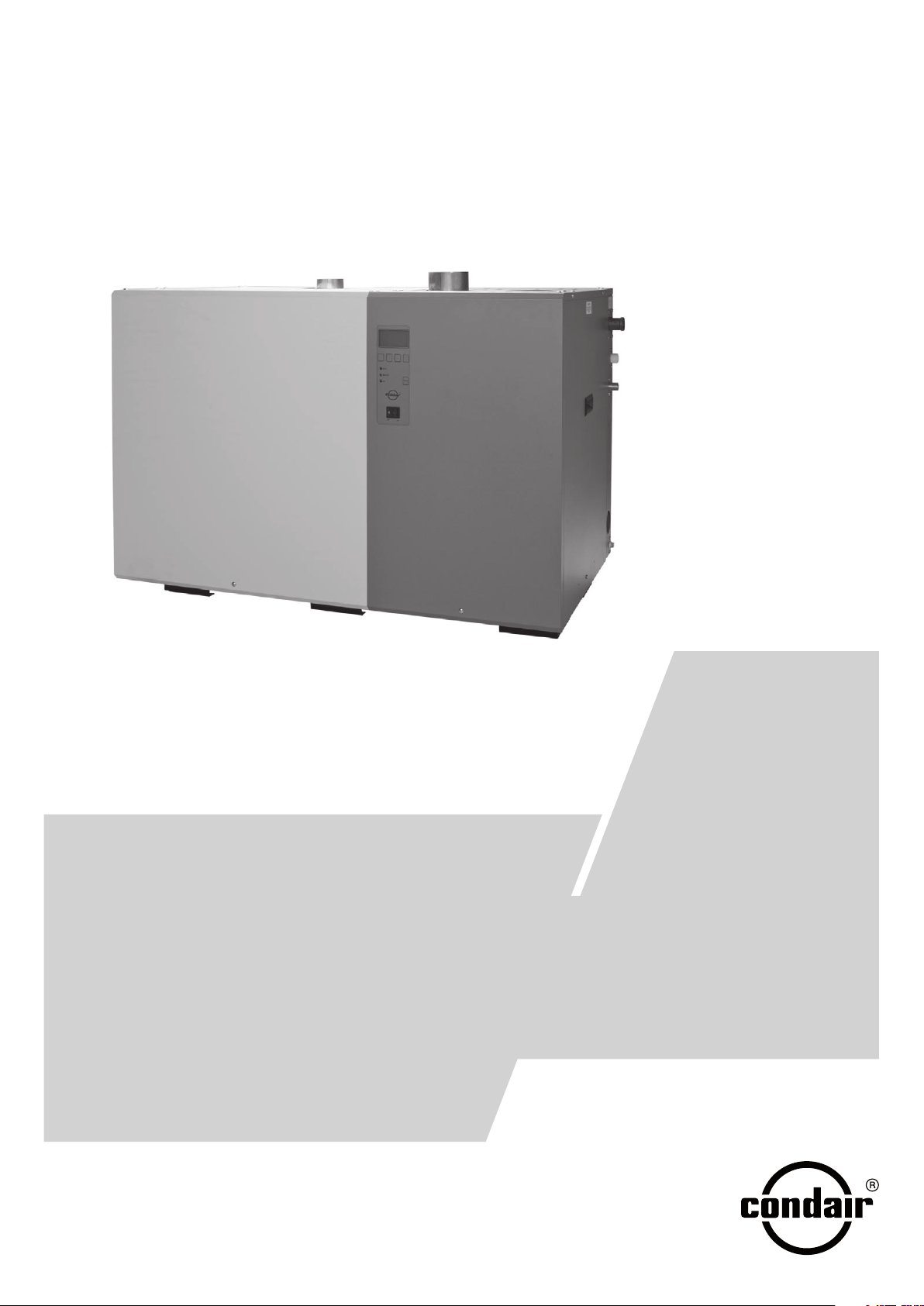
Condair GS… C series
Gasfired steam humidifier
INSTALLATION, COMMISSIONING AND
SERVICE INSTRUCTIONS
1119123 EN 0906
Page 2

Page 3

Contents
1 Introduction 4
1.1 At the very beginning 4
1.2 Notes on the installation, commissioning and service instructions 4
2 For your safety 6
3
3
3
3.2 Delivery 8
3.3 Humidification system overview 9
3.4 Construction of the gasfired steam humidifier 10
3.5 Principle of operation 11
4 Basic planning 13
4.1
4.2 Selecting the control system 15
4.3 Options 17
4.4 Accessories 17
5 Mounting and installation works 19
5.1
5.2 Unit fitting 20
5.3 Steam installation 24
5.4 Water installation 31
5.5 Gas installation 34
5.6 Flue gas installation 37
5.7 Installation of the air inlet line for room air-independent units (RS units) 42
5.8 Installation of control and monitoring devices 44
5.9 Electrical Installation 45
6 Inspecting the installations (Check list) 47
Product Overview 8
.1 Product versions/Model designations 8
Selecting the unit 13
Important notes on mounting and installation works 19
7 Operation 49
7.1
7.2 Function of the display and operating elements 50
7.3 Commissioning 51
7.4 Notes on operation 53
7.5 Taking the unit out of operation 53
8 Maintenance 54
8.1
8.2 Maintenance instructions 54
8.3 Dismantling work for maintenance and the replacement of components 56
8.4 Notes on cleaning agents 66
8.5 Resetting the maintenance reminder 66
9 Troubleshooting 67
9.1
9.2 Error indication 67
9.3 Resetting the error indication 67
10 Specifications 68
10.1
10.2 Flue gas specifications 69
Important notes on operation 49
Important notes on maintenance 54
Important notes on troubleshooting 67
Technical Data 68
Page 4

4
1 Introduction
1.1 At the very beginning
Thank you for deciding on the Condair GS C series Gasfired Steam Humidifier (abbreviated as
“Condair GS”).
The Condair GS incorporates the latest technical advances and satisfies the requirements of the
European Gas Equipment Directive (90/396/EEC) and all known safety standards. Nevertheless,
improper use may result in danger to the user or third parties and/or impairment of the installation
or other material assets.
To ensure a safe, proper, and economical operation of the Condair GS, please observe and comply
with all information and safety instructions contained in the present installation, commissioning and
service instructions as well as the instructions given in the manuals for the components used in the
humidification system.
If you have questions, which are not or insufficiently answered in this documentation, please contact
your Condair supplier. They will be glad to assist you.
1.2 Notes on the installation, commissioning and service instructions
Limitation
The subject of these installation, commissioning and service instructions is the Condair GS C series
Gasfired Steam Humidifier in its different versions. The various accessories are only described insofar
as this is necessary for proper operation of the equipment. Further information on accessories can
be obtained in the respective instructions.
These installation, commissioning and service instructions is restricted to the planning, installation,
commissioning, operation, servicing and trouble shooting of the gasfired steam humidifier Con-
dair
GS and is meant for well trained personnel being sufficiently qualified for their respective
work.
These installation, commissioning and service instructions are supplemented by various separate
items of documentation (operating instructions for Condair GS/GS...OC - C series control, spare
parts list, etc.). Where necessary, appropriate cross-references are made to these publications in
the installation, commissioning and service instructions.
Page 5

Symbols used in this documentation
CAUTION!
The catchword “CAUTION” designates notes in this documentation that, if neglected, may cause
damage and/or malfunction of the unit or other material assets.
WARNING!
The catchword “WARNING” used in conjunction with the general caution symbol designates safety
and danger notes in this this documentation that, if neglected, may cause to injury to persons.
DANGER!
The catchword “DANGER” used in conjunction with the general caution symbol designates safety
and danger notes in this this documentation that, if neglected, may lead to severe injury or even
death of persons.
Safekeeping
5
Please
safeguard these installation, commissioning and service instructions in a safe place, where
they can be immediately accessed. If the equipment changes hands, the installation, commissioning
and service instructions should be passed on to the new operator.
If the installation, commissioning and service instructions get mislaid, please contact your Condair
supplier.
Language
versions
These installation, commissioning and service instructions are available in various languages. Please
contact your Condair supplier for information.
Copyright protection
The present installation, commissioning and service instructions are protected under the Copyright
Act. Passing-on and reproduction of the installation, commissioning and service instructions (or
part thereof) as well as exploitation and communication of the contents are prohibited without written
permission by the manufacturer. Violation of copyright terms is subject to legal prosecution and
arises liability for indemnification.
The manufacturer reserves the right to fully exploit commercial patent rights.
Page 6

6
2 For your safety
General
Every person working with the Condair GS must have read and understood the installation, commissioning
Knowing and understanding the contents of the installation, commissioning and service instructions
is a basic requirement for protecting the personnel against any kind of danger, to prevent faulty operation, and to operate the unit safely and correctly.
If the information in these installation, commissioning and service instructions is not followed exactly, a fire or explosion may result causing property damage, personal injury or
loss of life.
All ideograms, signs and markings applied to the unit must be observed and kept in readable
state.
Qualification of personnel
and service instructions before carrying out any work.
All actions described in the present Installation, commissioning and service instructions (commissioning,
qualified personnel authorised by the owner.
For safety and warranty reasons any action beyond the scope of this manuals must be carried out
only by qualified personnel authorised by the Conair representative.
It is assumed that all persons working with the Condair GS are familiar and comply with the appropriate regulations on work safety and the prevention of accidents.
Intended use
The gas fired steam humidifier Condair GS is intended exclusively for humidification in ventilation
the express written consent of the manufacturer is considered as not conforming with the intended
purpose and may lead to the Condair GS becoming dangerous.
Operation of the equipment in the intended manner requires that all the information in these
installation, commissioning and service instructions is observed (in particular the safety
instructions).
Danger that may arise from the unit
operation, maintenance, etc.) must be carried out only by well trained and sufficiently
systems within the specified operating conditions. Any other type of application without
DANGER! Danger of electric shock
The Condair GS is mains powered. One may get in touch with live parts when the unit is
open. Touching live parts may cause severe injury or danger to life.
Prevention:
chapter 6.3 (switch off the unit, disconnect it from the mains and stop the water and gas supply)
and secure the unit against inadvertent power-up.
before carrying out any work set the Condair GS out of operation as described in
Page 7
DANGER! Danger of explosion
The Condair GS is working with gas. Improper installation, adjustment, alteration, service,
maintenance, or use can cause carbon monoxide poisoning, an explosion, fire, or other
conditions which may cause personal injury or property damage.
7
Prevention:
any work on the gas system must be carried out only by well trained and sufficiently
qualified personnel authorised by the owner. Before carrying out any work on the gas system set
the Condair GS out of operation as described in chapter 6.3. (switch off the unit, disconnect it from
the mains and stop the water and gas supply) and secure the unit against inadvertent power-up.
Do not store or use gasoline or other flammable vapors and liquids in the vicinity of this or any
other appliance
What to do if you smell gas: do not try to light any appliance. Do not touch any electrical switch;
do not use any telephone in your building. Immediately call your gas supplier from a neighbor’s
telephone. Follow the gas supplier’s instructions. If you can not reach your gas supplier, call the
fire department.
DANGER! Danger of burning
The water tank, the steam line and the exhaust system get very hot during operation.
There is danger of burning when touching these components during or shortly after operation.
Prevention:
Do not touch the water tank, the steam line and the exhaust system during operation.
Before carrying out any work set the Condair GS out of operation as described in chapter 6.3 , then
wait until the components has cooled down sufficiently thus preventing danger of burnin.
Behaviour in case of danger
If it is suspected that safe operation is no longer possible, then the Condair GS should immediately
be shut down and secured against accidental power-up according to chapter 6.3. This can be
the case under the following circumstances:
– if you smell gas
– if the Condair GS or its mains cable is damaged
– if the Condair GS is no longer operating correctly
– if connections and/or piping are not sealed
– if components of the Condair GS humidifier are worn or badly soiled.
– if the Condair GS or any components has been exposed to excess humidity.
– after longtime storage under unfavorable conditions.
– after transportation under unfavorable conditions.
All persons working with the Condair GS must report any alterations to the unit that may affect safety
to the owner without delay.
Prohibited modifications to the unit
No modifications must be undertaken on the Condair GS without the express written consent of
the manufacturer.
For the replacement of defective components use exclusively original accessories and spare parts
available
from your Condair supplier.
Page 8

8
3 Product Overview
3.1 Product versions/Model designations
The Condair GS gasfired steam humidifier is available in 6 different models with different maximum steam output performance (40, 80, 120, 160, 200 and 240 kg/h).
All models can be supplied in a version suitable for operation independent of the room air conditions
(With a separate air inlet) and can be operated with natural gas or propane (the unit is supplied Exworks for a specific type of gas operation).
Model designation
GS 40 C G20 RS
Product line
(gasred steam humidier with
operation and display unit)
Steam output (kg/h)
40
80
120
160
200
240
Equipment
Fuel
Natural gas H, E, E(S): G20
Natural gas L, ELL: G25
Natural gas HS: G25.1
Natural gas Lw: G27
Natural gas Ls: GZ350
Propane gas P: G31
Room air-independent unit
(with separate air intake)
The humidifiers are equipped with an operating and display unit, as standard, by means of which
the current operating parameters can be interrogated and the equipment can be configured for operation. The humidifiers are controlled via the internal PID controller or an external continuous
controller.
series
3.2 Delivery
The standard delivery includes:
– Gasfired steam humidifier Condair GS compl. with unit stand (according to the model designa-
tion)
–
Installation, commissioning and service instructions Condair GS C series
– Operating instructions Condair GS control
– Spare parts list
– Accessories ordered according to chapter 4.4 (steam distribution pipes, steam hoses, etc.).
Page 9
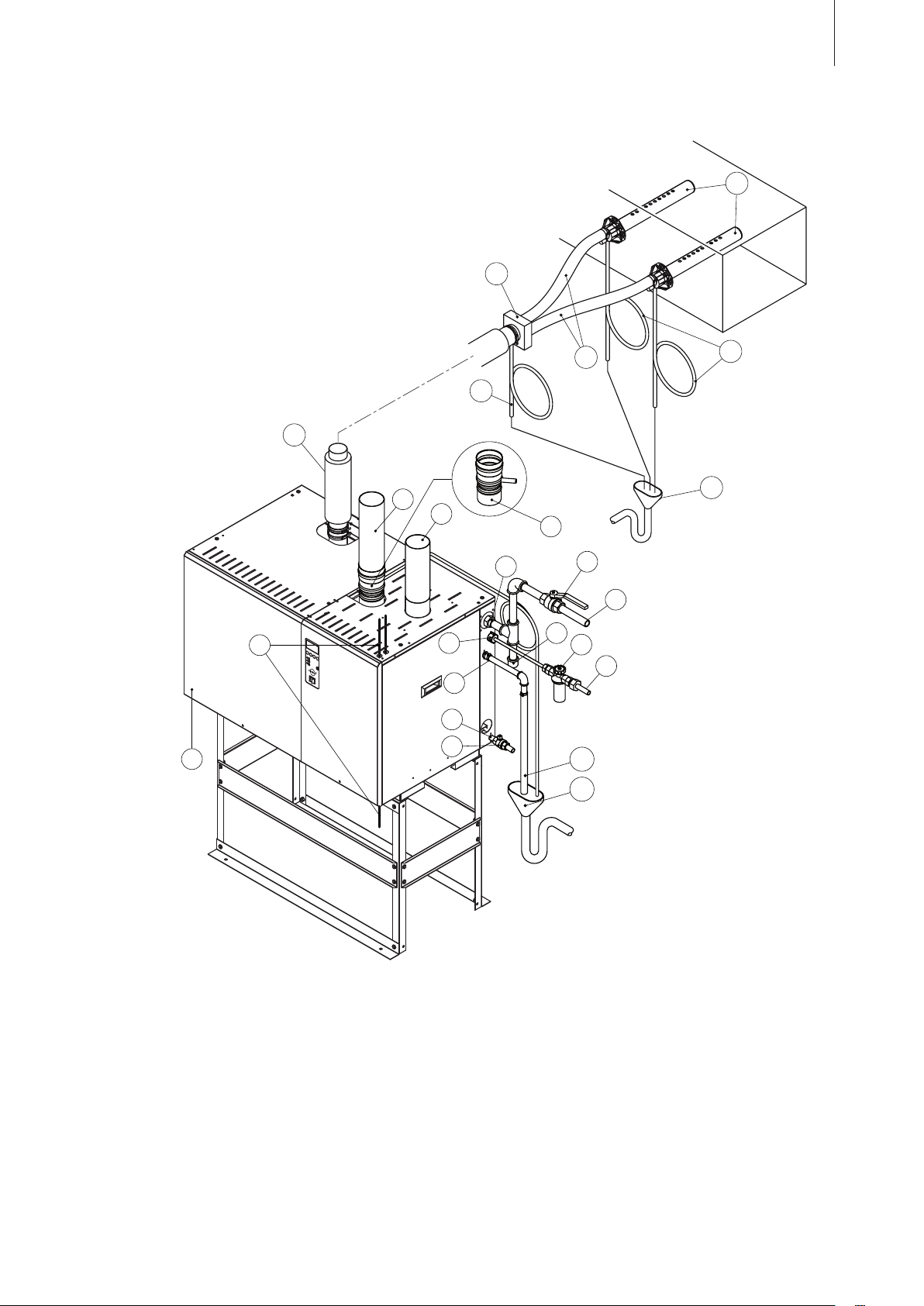
3.3 Humidification system overview
1
10
5
8
9
15
16
12
14
13
17
2
4
3
7
6
11
12
21
19
18
22
20
22
9
1 Gasfired steam humidifier
2 Electrical connections
3 Gas supply connection
4 Shut-off valve gas supply line (building side)
5 Gas supply line (building side)
6 Sediment trap (building side)
7 Fill water connection
8 Filter valve (accessory “Z261”)
9 Water supply line (building side)
10 Drain water connection
11 Drain water line
12 Funnel with trap
13 Auxiliary drain connection
14 Shut-off valve auxiliary drain (building side)
15 Flue gas pipe
16 Flue gas adapter with condensate drain
(accessory “FA...”)
17 Air intake pipe (RS-units only)
18 Main steam pipe (building side)
19 Steam hose adapter (accessory “SA...”)
20 Steam hose (accessory “DS80”)
21 Steam distribution pipe (accessory “81–...”)
22 Condensate hose (accessory “KS10”)
Page 10
10
3
4
2
1
15
22
19
20
23
24
25
26
27
21
28
29
14
17
18
16
5 6
10
7 98
12
1311
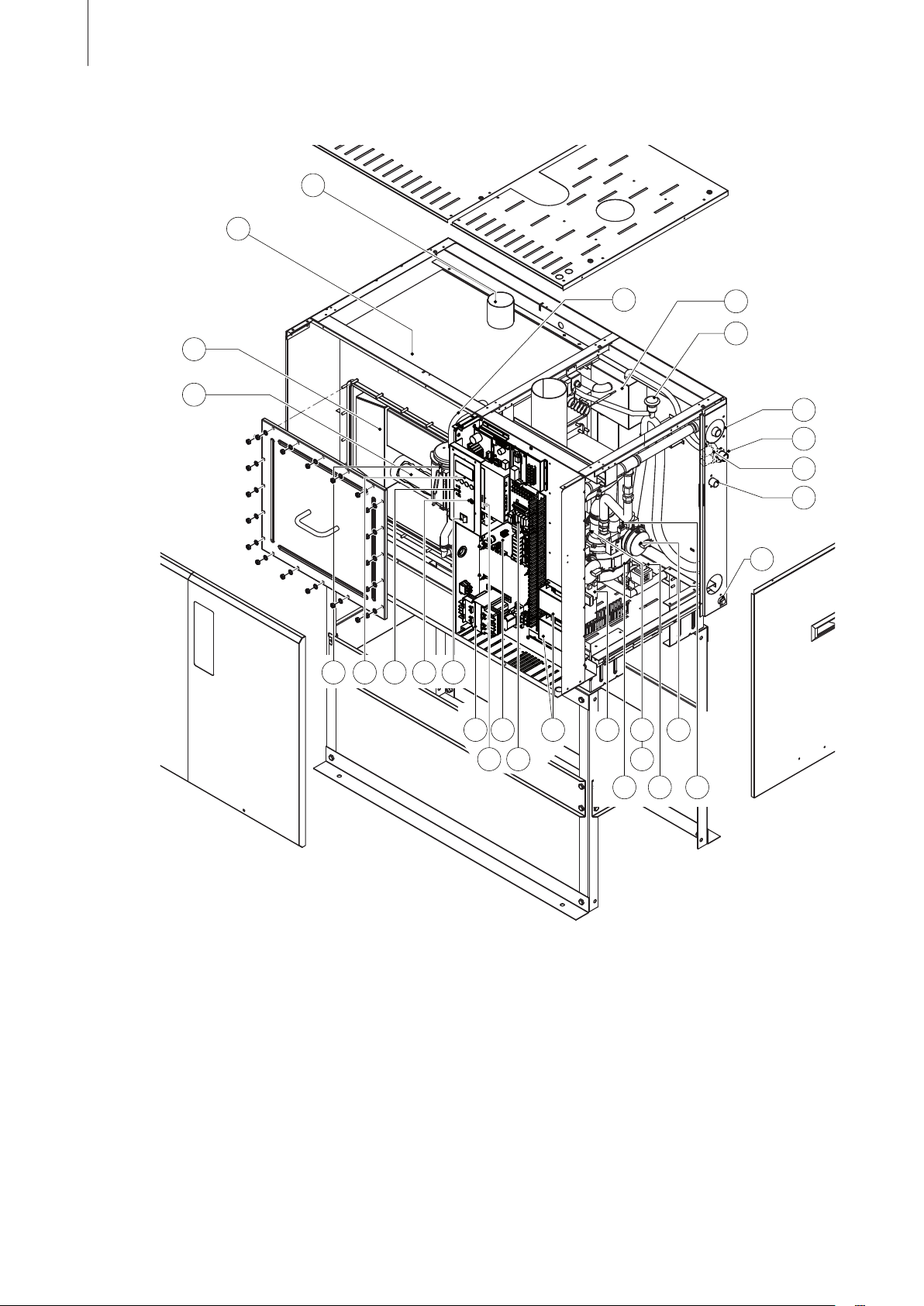
3.4 Construction of the gasfired steam humidifier
1 Water tank
2 Steam outlet(s) (1 to 6)
3 Heat exchanger (1 to 3)
4 Burner (1 to 6)
5 Level unit
6 Key pad and display unit
7 Indication LED’s
green: “Steam production”
yellow: “Maintenance”
red: “Error”
8 Drain key (manual draining)
9 Unit switch
10 Tansformer
11 Control board
12 Driver board
13 Remote operating and fault indication board
14 Ignition modules
15 Burner electronic
16 Combustion air blower (1 to 6)
17 Flame sensor
18 Igniter
19 Drain pump
20 Air pressure switch
21 Gas pressure control valve (1 to 6)
22 Auxiliary drain line
23 Drain connection
24 Double inlet valve filling water
25 Connection filling water
26 Connection gas supply line
27 Vacuum break
28 Filling chamber
29 Pressure equalizer line (level unit)
Page 11
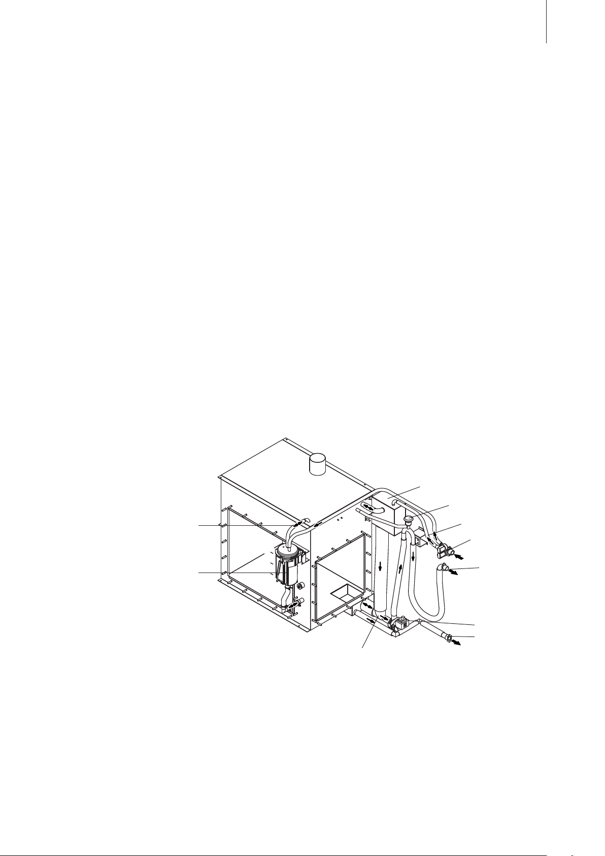
C
B
A
3.5 Principle of operation
Combustion System
The combustion system is based on a fully modulating forced draft combustion air blower, a negative
pressure regulator gas valve and a 100% premix burner. On a call for humidity, the combustion air
blower starts and creates a negative pressure across an orifice located at the air inlet. The blower
starts for a moment to purge the system, then the hot surface ignitor is activated for 15 seconds.
During this time the electronic ignition module does a diagnostic check of safety systems including
the air proving switch which senses the negative pressure at the air inlet.
After the function of the safety systems has been verified, the gas valve will open and the gas/air
mixture is ignited by the hot surface ignitor. If flame is sensed by the flame sensor within 3 seconds
the gas valve remains open and combustion continues. If flame is not sensed, the above sequence
is repeated a maximum of three times after which the ignition module will lock out and a respective
error message will appear in the display.
The gas valve maintains a constant ratio of air to Natural Gas or Propane independent of blower
speed or external conditions. This air and fuel is thoroughly mixed in the blower and then forced
through the burner ports where ignition occurs.
Hot products of combustion are forced through a baffle inside the heat exchanger and then vented
outside. The heat exchanger has large vertical surfaces to minimize scale build-up and promote scale
shedding to the bottom of the tank. This self-cleaning action helps to maintain the efficiency of the
heat exchanger while the smooth surfaces allow for easy cleaning when necessary.
11
The GS 40 has a single combustion chamber/heat exchanger. The combustion system is duplicated
on larger units with multiple chambers inside a common tank.
Regulation of the water level in the tank
Filling chamber
Vacuum break
Pressure equalizer
Main fill line
Double fill valve
Level unit
Drain outlet
Drain pump
Auxiliary drain
Mixing pipe
The level in the water tank is continuously monitored by the level unit. On initial start-up, the control
unit checks the function of the level unit. During this test the tank is filled up first to level “A”, then
drained to level “C” and filled up again to level “A”. As soon as level “B” is reached and the test of the
level unit was successful the humidifier is ready for operation, if a humidification demand is present
the combustion process starts.
Page 12

12
When the water level due to the evaporation process reaches level “B”, the level unit sends a signal
to the control system, which opens the double inlet valve and the water tank is filled up. On reaching level “A”, the level unit again sends a signal to the control system and the double inlet valve is
closed.
If the water level goes below level “C”, the combustion will be interrupted until the water level reaches
“C” again.
To ensure safe operation, the control system constantly monitors the proper function of the level unit
in regular intervals.
Steam generation/control
The steam is generated in the water tank via the heat exchanger/s. The steam production is regulated
continuously by the internal PID controller or an external continuous controller.
Flushing
The
concentration of minerals in the water in the tank increases due to the evaporation process. In
order that this concentration does not exceed a specified value, an appropriate quantity of water is
pumped off from the tank at a fixed time interval and replaced by fresh water. These flushing cycles
are based on steam production to increase the efficiency of the humidifier.
When a flushing cycle is initiated the drain pump is activated and the inlet valve opens. In the mixing
pipe below the filling chamber the hot drain water is mixed with the cold cooling water and leaves
the unit with a temperature approx. around 60 - 70 °C.
If the lowest operating level is reached in the tank during the flushing process, the inlet valve remains
open until the water level in the tank has again reached the normal operating level.
Page 13
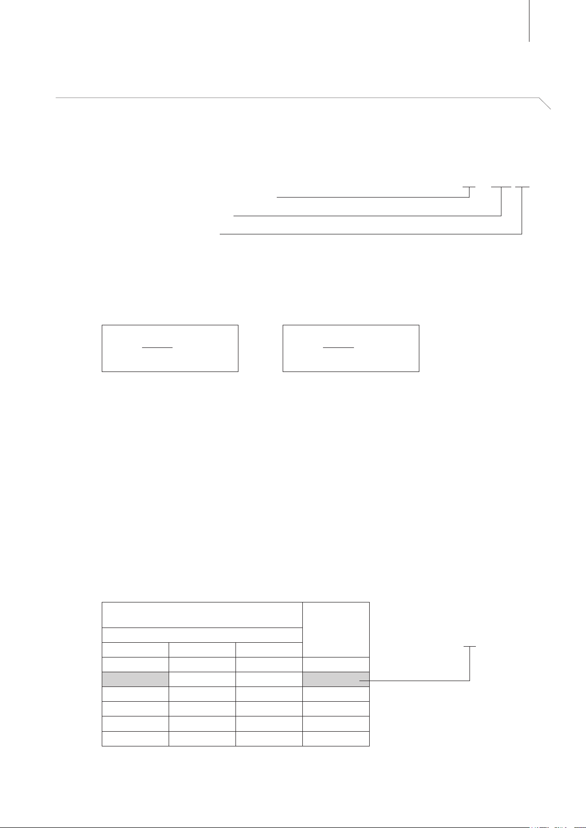
4 Basic planning
4.1 Selecting the unit
The selection of the unit is reflected in the type description:
1. Required maximum steam capacity
2. Required combustion gas
3. Combustion air supply
4.1.1 Calculating the maximum required steam capacity
The maximum required steam capacity is calculated from the following formulas:
13
Condair GS 80 C G20 RS
V•ρ
mD = • (x2 - x1)
1000
mD: maximum steam demand in kg/h
V: volume of supply air portion per hour in m3/h (for indirect room humidification) or room volume
to be humidified per hour in m3/h (for direct room humidification)
ρ: specific gravity of air in kg/m
ε: specific volume of air in m3/kg
x2: desired absolute room air humidity in g/kg
x1: minimum absolute supply air humidity in g/kg
The values for ρ, ε, x2 and x1 can be gathered from the h,x-diagram or the Carrier-Diagram for moist
air respectively.
For a rough estimate of the calculated steam capacity, the following table can be used. The values
listed in the table are based on a desired room air temperature of 20 °C and a desired relative room
air humidity of 45 %rh.
Note: To roughly estimate the calculated maximum steam capacity for larger supply air portions or
room volumes, the values listed in the table can be projected accordingly.
Max. portion of supply air in m3/hr or room vol-
ume to be humidified per hour in m3/hr
Temperature / rel. humidity of supply air
-15°C / 90%rh -5°C / 80%rh 5°C / 60%rh
5000 6600 8000 40
10000 13200 16000 80
15000 19800 24000 120
20000 26400 32000 160
25000 33000 40000 200
30000 39600 48000 240
or
3
V
mD = • (x2 - x1)
1000•ε
max. steam
capacity
in kg/h
Condair GS 80 C G20 RS
Example:
Max. portion of supply air 10000 m3/h,
temperature/rel. humidity of supply air
-15°C/90%rh
Page 14
14
Important notes:
– The required maximum steam capacity depends on the specific application and the installation.
The calculated steam capacity based on the above formulas, the h,x diagram and the condition of
the air to be humidified does not consider any steam loss (e.g. due to condensation in the steam
hoses and the steam distributors), any heat loss of the unit as well as any absorption or release
of humidity of materials located in the room being humidified.
In addition, the calculated steam capacity does not consider any losses caused by the draining
rate depending on the water quality.
The total amount of losses depends on the entire system and must be taken into consideration
when calculating the required steam capacity. If you have any questions regarding the calculation
of the steam capacity please contact your Condair supplier.
– For systems where the max. required steam capacity varies extensively (e.g. for test facilities or
for systems with variable air volume flow, etc.), please contact your Condair supplier.
4.1.2 Combustion gas
The Condair GS can be operated with natural gas or propane. The equipment is configured ex-
works for the respective combustion gas that is to be employed. If required, the equipment can be
converted at a later date to work with one of the other combustion gas.
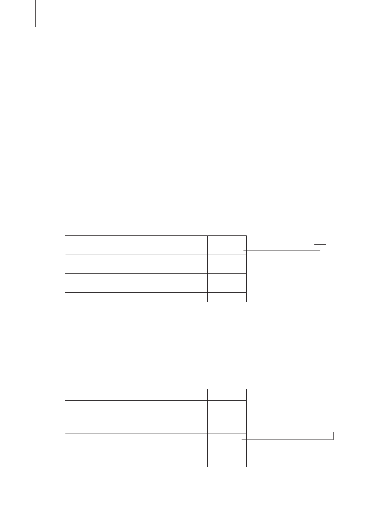
Combustion gas Designation
Natural gas H, E, E(S) G20
Natural gas L, ELL G25
Natural gas HS G25.1
Natural gas Lw G27
Natural gas Ls GZ350
Propane gas P (Liquid gas) G31
4.1.3 Combustion air supply
To ensure correct combustion, care must be taken to provide either a ventilation opening in the
room where the equipment is installed (room air-dependent device) or a separate air inlet pipe
(room air-independent device) so that an adequate supply of clean, fresh air, is available.
Condair GS 80 C G20 RS
Equipment version Designation
Room air-dependent device
For rooms with a sufficiently large ventilation opening
and a source of clean intake air.
Caution! Local building regulations must be observed.
Room air-independent device (RS equipment)
Air supply through a separate pipe from outside the
building. For closed rooms, rooms with low air pressure
and rooms with dirty intake air.
___
RS
Condair GS 80 C G20 RS
Page 15
4.2 Selecting the control system
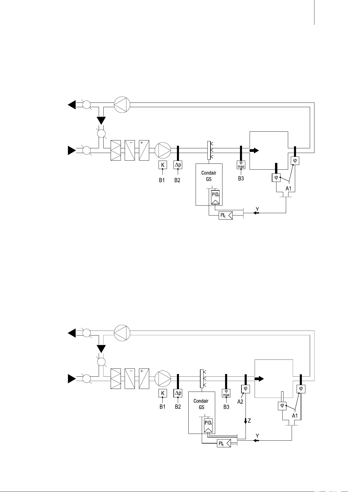
The various control systems
15
– System
1: Room humidity control
System 1 is suited for air conditioning systems with mainly recirculated air. The humidity sensor
is preferably located in the room itself or in the exhaust air duct.
A1 humidity sensor
B1 ventilation interlock
B2 airflow monitor
B3 safety humidistat
external continuous controller (e.g. PI controller)
PI
E
PIDI internal continuous controller (PID controller)
Y input signal from A1
– System 2: Room humidity control with continuous limitation of the supply air humidity
System 2 is suited for air conditioning systems with a large portion of supply air, low supply air
temperature, post-humidification, or variable airflow volume. If the supply air humidity exceeds
the preset value, the continuous limitation is effected prior to the room humidity control.
The humidity sensor (A1) is preferably located in the exhaust air duct or in the room itself. The
humidity sensor (A2) for the limitation of the supply air humidity is located in the supply air duct
after the steam distribution pipe. This control system requires the internal PID controller or an
external continuous controller with the option to connect a second humidity sensor.
Attention! The
continuous limitation of the supply air humidity is no substitute for the safety
humidistat.
A1/2 humidity sensor
B1 ventilation interlock
B2 airflow monitor
B3 safety humidistat
PIE external continuous controller (e.g. PI controller)
PIDI internal continuous controller (PID controller)
Y input signal from A1
Z input signal from A2
Page 16
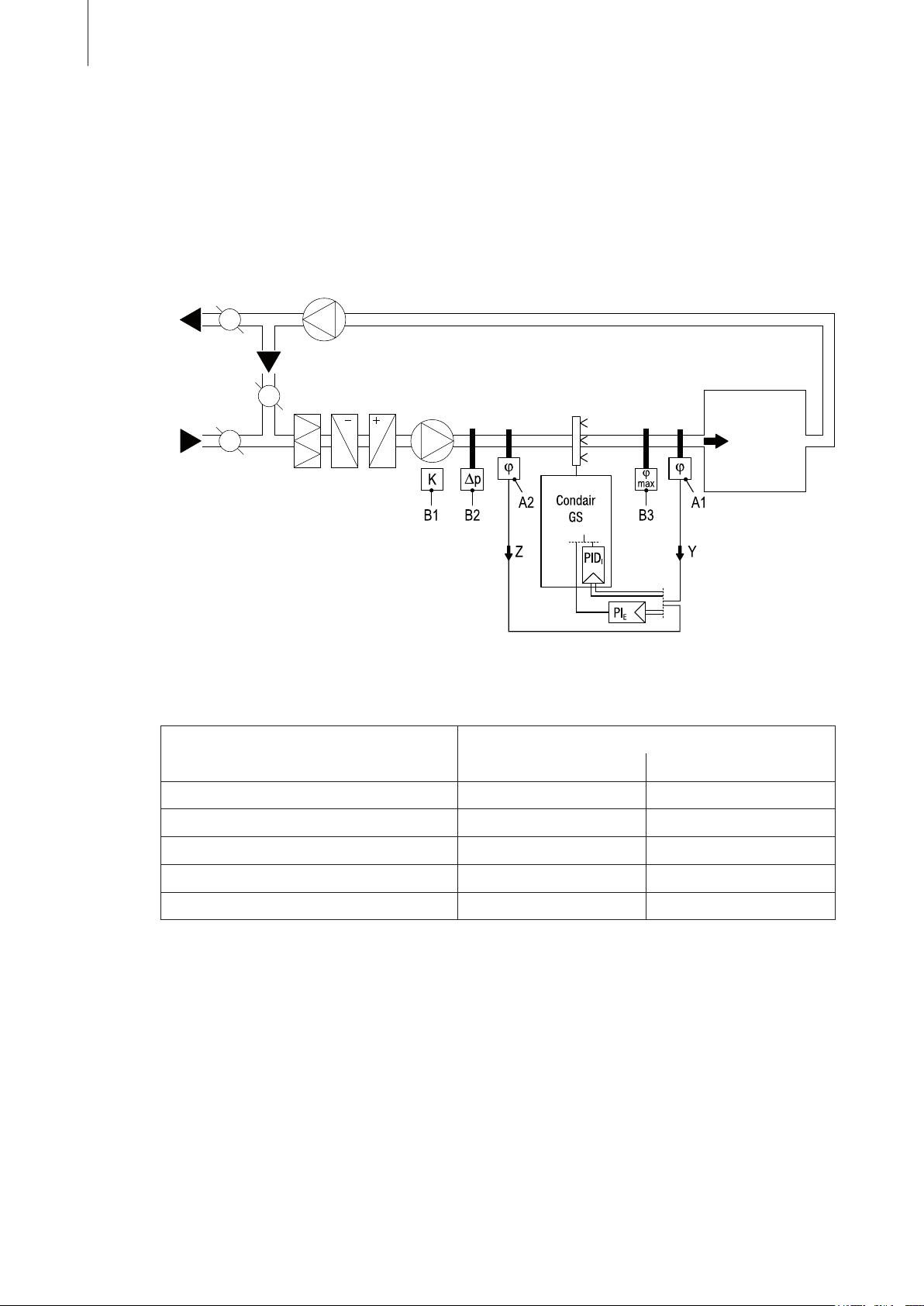
16
– System 3: Supply air humidity control with continuous output limitation
Supply air humidity control (humidity sensor installed in supply air duct) should be used only
where room humidity control is impracticable for technical reasons. Such systems always require
a PI-controller.
The humidity sensor (A1) is located in the supply air duct after the steam distribution pipe. The
humidity sensor (A2) for the continuous output limitation is located in the supply air duct before
the steam distribution pipe. Such a system requires the internal PID controller or an external PIcontroller with the option to connect a second humidity sensor.
A1/2 humidity sensor
B1 ventilation interlock
B2 airflow monitor
B3 safety humidistat
PIE external PI-controller
PIDI internal continuous controller (PID controller)
Y input signal from A1
Z input signal from A2
Which humidity control system for which application?
Application Location of the humidity sensor
Room or exhaust air duct supply air duct
Air conditioning systems with:
Supply air portion up to 33% System 1 System 1
Supply air portion up to 66% System 1 or 2 System 2 or 3
Supply air portion up to 100% System 2 System 3
Supply air humidity control
––– System
Please contact your Condair supplier, if your application meets the following conditions:
– Humidification of small rooms up to 200 m
3
3
– Air conditioning systems with a high number of air exchanges
– Systems with variable air volume flow
– Test facilities with extreme control accuracy requirements
– Rooms with a high variation in max. steam capacity
– Systems with temperature fluctuations
– Cold rooms and systems with dehumidification
Page 17
Control/input signals
The Condair GS is regulated via the internal PID controller or an external continuous controller (e.g.
PI controller).
Important! For
the control systems 2 and 3 the external controller must be equipped with two control
signal inputs.
The Condair GS processes the following control signals:
– 0 ... 10 VDC
– 2 ... 10 VDC
– 0 ... 10 mADC
– 2 ... 10 mADC
– 0 ... 20 mADC
– 4 ... 20 mADC
– 0 ... 5 VDC
– 1 ... 5 VDC
Further information is provided in Chapter 5.9.
Output signals
The Condair GS provides the following output signals:
17
– 10 VDC (max. 20 mA)
– Remote operating and fault signals (4 potential-free contacts)
Further information is provided in Chapter 5.9.
4.3 Options
At the moment no options are needed for the Condair GS.
4.4 Accessories
4.4.1 Accessories overview
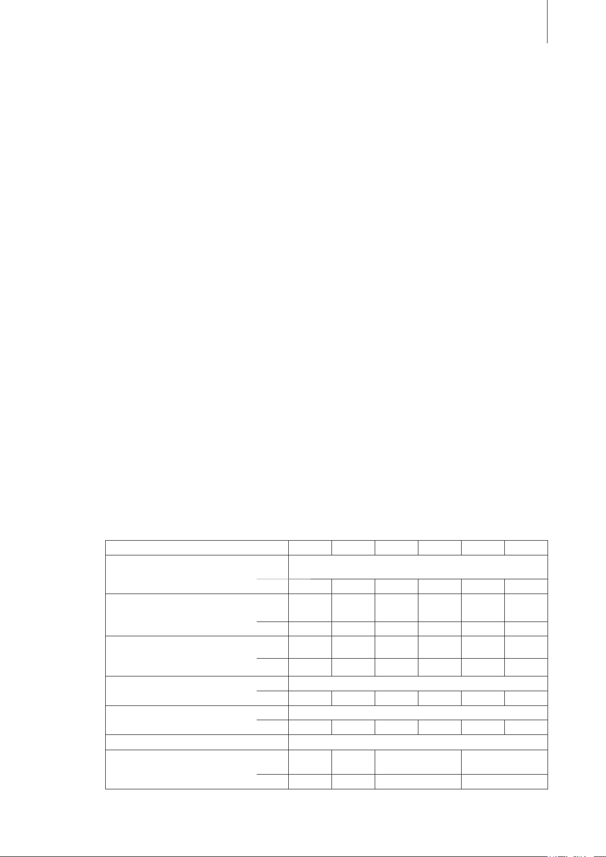
Model Condair GS 40 ... 80 ... 120 ... 160 ... 200 ... 240 ...
Steam distribution pipe
(see accessory details in chapter 4.4.2)
OptiSorp
(see accessory details in chapter 4.4.2)
Steam hose adapter ––– SA80
steam distribution system
81-...
number 1 2 3 4 5 6
System 1 System 2 System 3 System 4 System 2
System 3
number 1 1 1 1 1
(3" / 2x 1 3/4")
number ––– 1 1 1 1 1
SA120
(3" / 3x 1 3/4")
SA160
(4" / 4x 1 3/4")
of each 2
SA200
(4" / 6x 1 3/4")
System 3
SA240
(4" / 6x 1 3/4")
Steam hose / meter DS80
number 1 2 3 4 5 6
Condensate
Filter
Flue gas adapter with
condensate drain
hose / meter KS10
number 1 2 3 4 5 6
valve Z261
FA40 FA80 FA120/160 FA200/240
number 1 1 1 1
(1 pc. per system)
Page 18
18
4.4.2 Accessory details
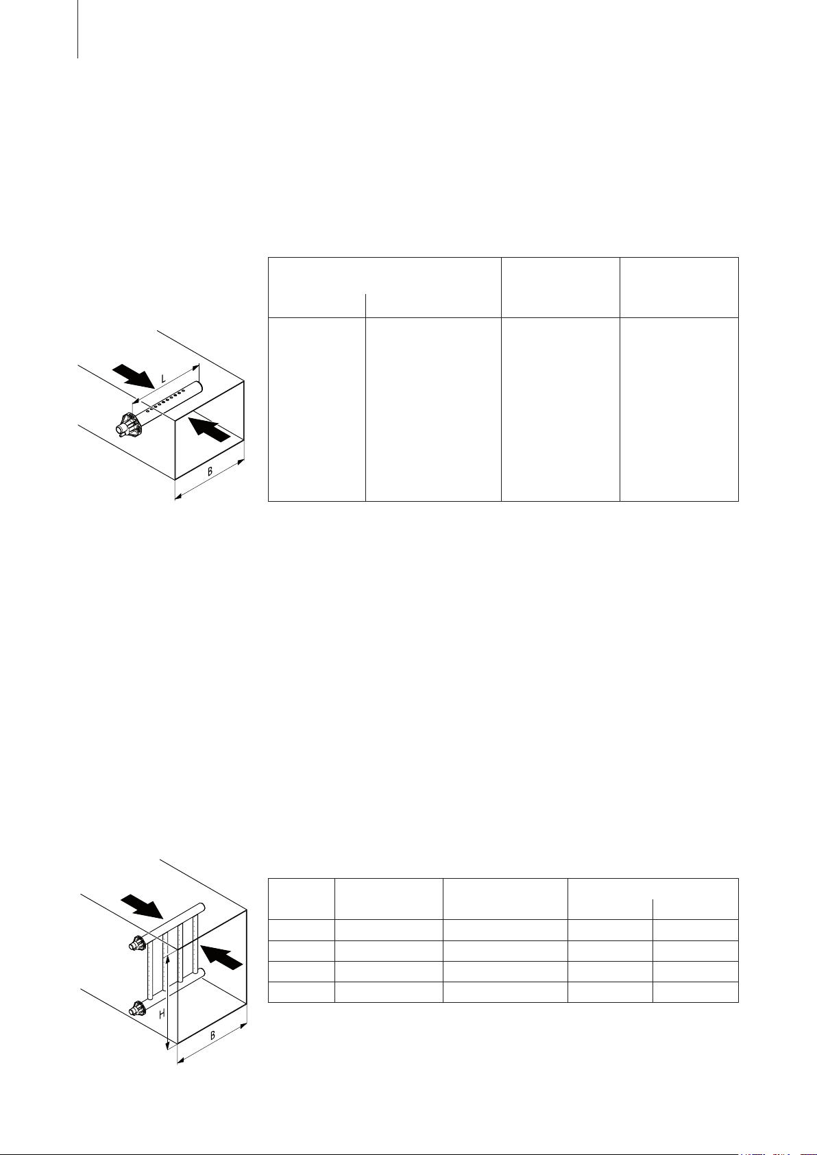
Steam distribution pipes
The steam distribution pipes are selected on the basis of the duct width (for horizontal installation)
or the duct height (for vertical installation) and the capacity of the steam humidifier.
Important! Always
tance).
select the longest possible steam distribution pipe (optimum humidification dis-
Steam distribution pipes
GS 40, 80, 120, 160, 200 and 240
Type Length
81-350 350 400…600 30
81-500 500 600…750 3
81-650 650 750…900 50
81-800 800 900…1100 50
81-1000 1000 1
81-1200 1200 1
81-1500 1500 1600…2000 50
81-1800 1800 2000…2400 50
81-2000 2000 2200…2600 50
300 2300 2500…2900 50
81-2
81-2500 2500 2700…
1)
Material: CrNi steel
2)
Special length on request
3)
To fully exploit the overall capacity of your GS humidifier, the output of each
1)
for
in mm (L)
Duct width (B) Steam capacity
2)
in mm max. in kg/h
100…1300 50
300…1600 50
3100 50
3)
0
steam outlet may be fed to more than one distribution pipe. If more than one
steam distribution pipe is fed per steam outlet the steam line must be divided
into multiple branches. Appropriate fittings are available on request.
Note:
If the humidification distance (see chapter 5.3.1) has to be reduced for technical reasons, the
steam output of your unit must be divided between two steam distribution pipes or the OptiSorp
steam distribution system must be used. If this is the case, contact your Condair supplier.
OptiSorp steam distribution system
The OptiSorp steam distribution system is used in ventilation ducts with a short humidification distance
(for the calculation of the humidification distance refer to chapter 5.3.1). When ordering an OptiSorp
system the duct dimension must be specified. Please consult the data in the following table.
OptiSorp Number of steam
connections
System 1 1 45
System 2 2 90
System 3 3 1
System 4 4 180
1)
For duct widths <600 mm the values in brackets apply
Max. steam capacity
in kg/h
1)
(30) 450...4000 450...1650
(60) 450...4000 450...2200
35 (90) 450...4000 800...3200
(120) 450...4000 800...3200
Duct dimensions
Width in mm Height in mm
Page 19

5 Mounting and installation works
5.1 Important notes on mounting and installation works
Qualification of personnel
All mounting and installation work must be performed only by adequately qualified personnel familiar
with the Condair GS. Ascertaining the qualifications is the customer‘s responsibility.
General notes
All the information contained in these installation, commissioning and service instructions relating to
equipment assembly and to gas, flue gas, water, steam and electrical installation must be uncondi
tionally
The local directives and regulations for the installation of gasfired equipment (Steam humidifiers)
must be unconditionally observed and complied with.
All local regulations relating to the execution of gas, flue gas, water, steam and electrical installations
must be observed and complied with.
observed and complied with.
19
-
Safety
connection of the Condair GS to the mains electrical supply must not be made until all installa-
The
tion
work has been completed.
Incorrectly executed installations can result in personal injury and/or damage to property through
explosions, fires, carbon monoxide poisoning, electric shock, etc. If you require assistance, please
contact a qualified installer, your local gas supplier or your Condair representative. In the installation
itself, use only materials available from your Condair representative and accessories approved by
him.
Page 20
20
5.2 Unit fitting
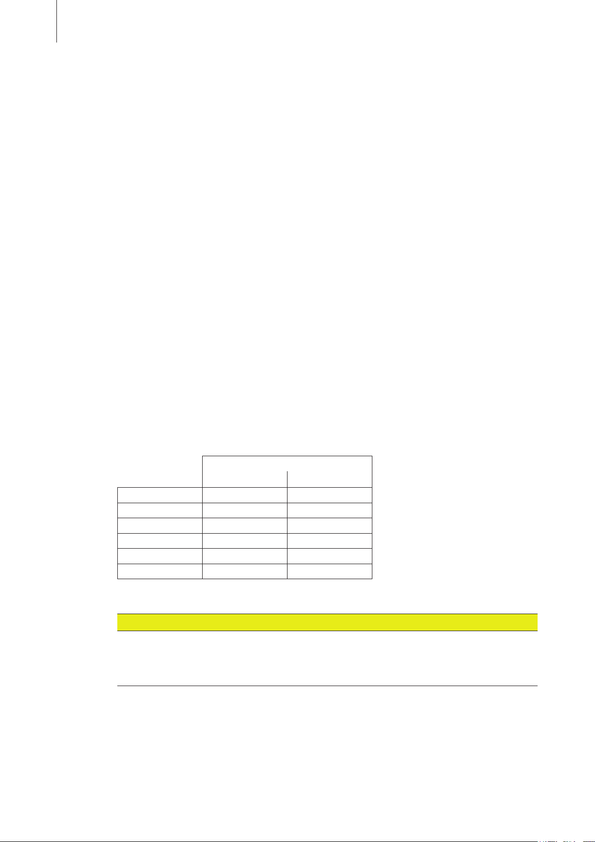
5.2.1 Humidifier location
The positioning of the Condair GS is largely dependent on the location of installation of the steam
distribution pipe (see Chapter 5.3.1) and on the details of the flue gas pipe (see Chapter 5.6) and the
air supply line (RS units only, see Chapter 5.7). To ensure proper functioning of the steam humidifier and to obtain optimum efficiency, the following points must be considered and observed when
choosing the location for the steam humidifier:
– the local and national regulations for installation of gasfired equipment must be observed and
followed. The manufacturer accepts no liability for non-compliance with these regulations.
– Install the steam humidifier so that :
– the length of the steam hose is as short as possible (ideally 2 m, max. 4 m), the minimum
bend radius (R= 300 mm) and the minimum upslope (20 %) and the minimum downslope (5
%) of the steam hose can be maintained (see Chapter 5.3.2).
Note: Long steam lines reduce the maximum steam output of the humidifier, due to the heat
loss involved. The static pressure also increases.
– the flue gas pipe can be installed in accordance with the applicable local building and instal
regulations.
lation
– in the case of room air-independent units (RS units) the installation location can be reached
with an air supply line and good accessibility is assured.
– In the case of room air-dependent units care must be taken to provide an adequate intake of air
(in accordance with local building regulations).
For UK only: Please refer to BS 5440: Part II or BS 6644 when installing units. We draw your at
tention
especially to combustion an ventilation air supply requirements for plant rooms. Permanent
low and high level openings communicating directly with the outside air shall be fitted with grilles
having a total minimum free area as follows.
Free area grille sizes
Low level High level
GS 40 14,400 mm
GS 80 55,800 mm
GS 120 70,200 mm
GS 160 84,600 mm
GS 200 89,000 mm
GS 240 113,400 mm
2
2
2
2
2
2
14,400 mm
27,900 mm
35,100 mm
43,300 mm
50,500 mm
57,700 mm
2
2
2
2
2
2
The room air-independent humidifiers (RS units) do not require a separate ventilation opening,
since the combustion air required is provided by an air intake pipe from outside the building.
-
-
CAUTION!
Operation of the humidifier with unclean air can lead to safety problems and reduce the output
of the unit. Impurities in the air are, for example: Halogens, ammonia, chloride, excessive dust,
lime and dirt. For questions about air quality, please refer to the technical service department
of your Condair distributor
– The Condair GS gasfired steam humidifiers are designed for floor mounting on the unit stand
(included in the delivery) fixed to the floor.
– The sheet covering of the Condair GS heats up during operation (max. surface temperature approx.
60 - 70 °C). Therefore make sure that no heat-sensitive materials are placed in the immediate
vicinity of the humidifier.
Page 21
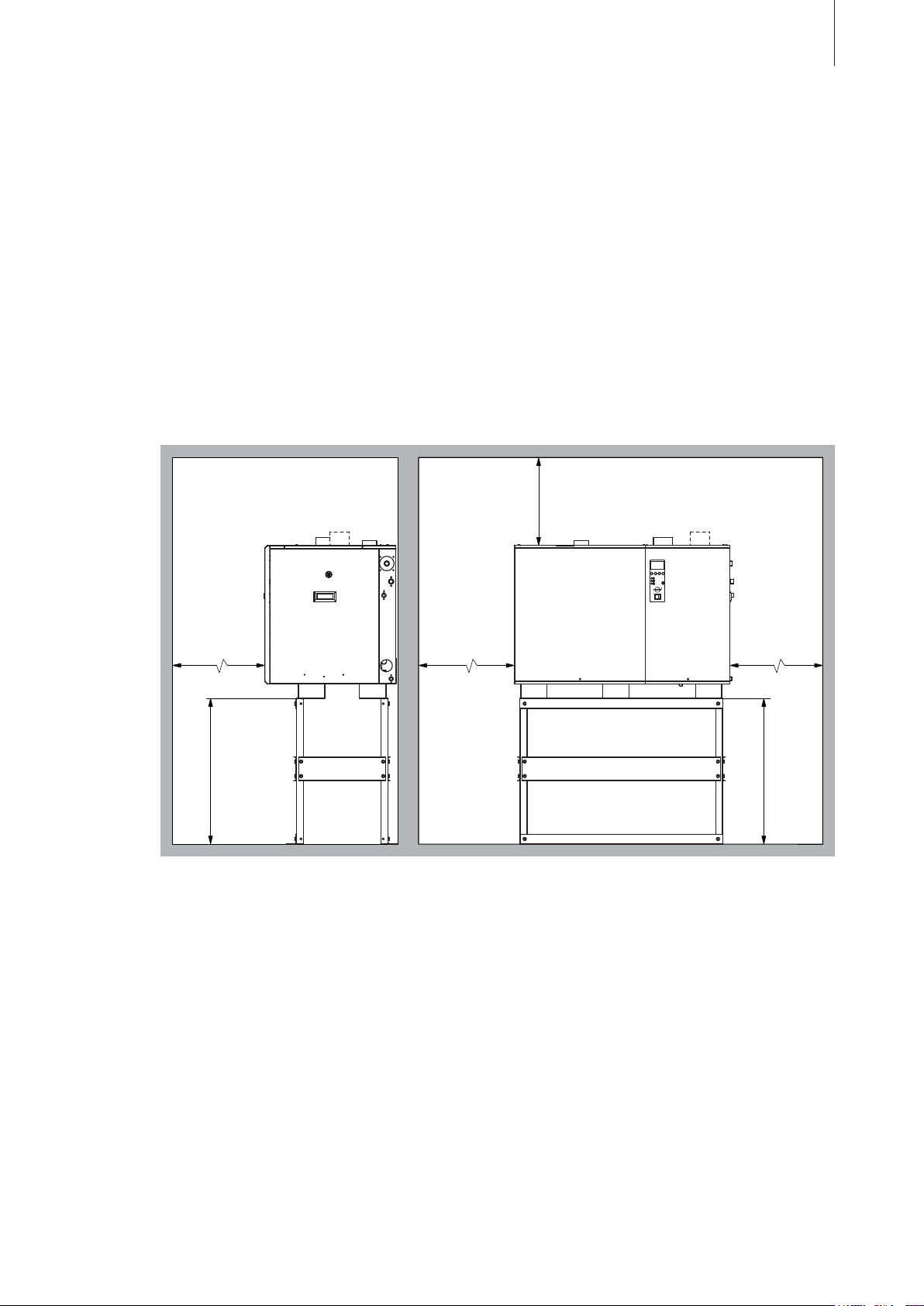
– No combustible materials must be placed in the immediate vicinity of the Condair GS humidifier
(Insulation materials, wooden floor coverings, etc.). Observe local regulations!
– Do not mount the humidifier in a location that is endangered by heat or frost! If the humidifier must
be mounted outside, it must be housed in a weatherproof and thermostatically ventilated cabinet.
If necessary, please contact your Condair representative.
– Do not mount the humidifier on a base that is subject to vibration. If necessary, please contact
your Condair representative.
– The Condair GS must be installed only in locations equipped with a water drain or with sensors
that safely interrupt water supply in case of leakage.
– Do not cover the air openings in the top and bottom covers of the humidifier housing otherwise
the air flow may be insufficient. Furthermore, do not place the unit in a narrow niche or a closed
compartment (observe minimum distances).
21
– Position the humidifier so that the unit is easily accessible and there is sufficient space for main
tenance
min. 1000 mm
work. The minimum distances shown in the following illustration must be maintained.
min. 1000 mm
min. 1000 mm
769 mm
min. 1000 mm
769 mm
-
Page 22
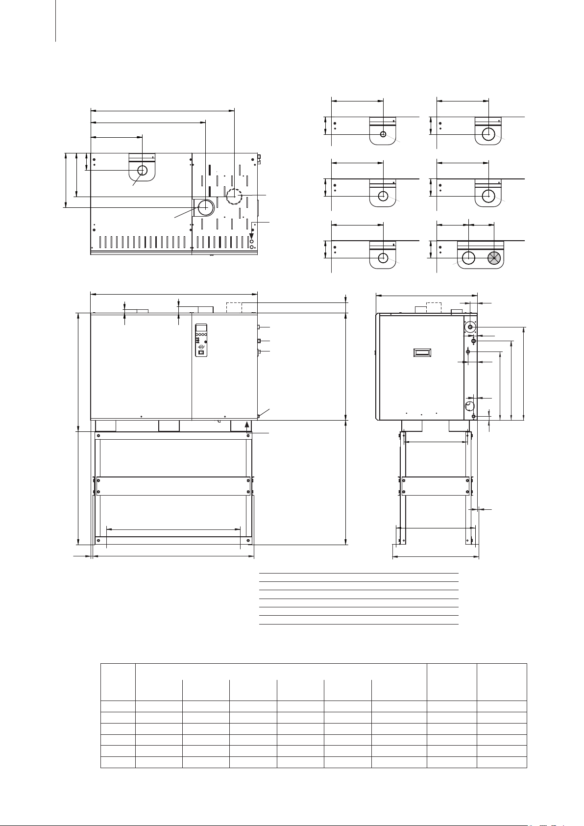
22
D
27
26
64
465
26
538
48
633
15 1094
12
E
F
974
780
353
1133
844
727
72
802
769
25
43
A
B
C
4"
353
139
GS 160
353
139
GS 40
1 3/4"
907
3"
353
139
GS 120
3"
353
139
GS 80
4"
353
139
GS 200
4"
250 203
139
GS 240
139
Dimensions (in mm)
Steam outlet
Flue gas outlet
Air intake
(RS units only)
Control signal
Gas supply
Water supply
Water drain
Auxiliary
water drain
Power supply
A B C D E F
GS 40 528 271 377 421 236 160
GS 80 689 431 537 588 372 295
GS 120 1086 827 933 984 371 278
GS 160 1086 827 933 984 371 278
GS 200 1482 1224 1330 1381 366 187
GS 240 1482 1224 1330 1381 366 187
Connections and weights
Model Connections Net
Flue gas Steam
No.
x ø
GS 40 3" 1 x 1 3/4" BSP 3/4" BSP 1/2" 3/4" NPT 1/2" 140 211
80 4" 1
GS
GS 120 5" 1
GS 160 5" 1
GS 200 6" 1
GS 240 6" 1
x 3" BSP 3/4" BSP 3/4" 3/4" NPT 1/2" 162 273
x 3" BSP 3/4" BSP 1" 3/4" NPT 1/2" 238 459
x 4" BSP 3/4" BSP 1" 3/4" NPT 1/2" 261 471
x 4" BSP 3/4" BSP 1 1/4" 3/4" NPT 1/2" 290 610
x 4" BSP 3/4" BSP 1 1/4" 3/4" NPT 1/2" 314 623
Filling
Water
Gas Water
Drain
Auxiliary
Water Drain
weight
kg
Operating
weight
kg
Page 23
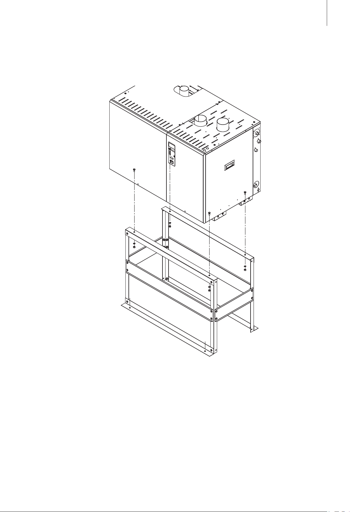
5.2.2 Mounting the humidifier
The Condair GS humidifiers must be mounted on the unit stand supplied with the unit. If mounting
on the unit stand supplied is not possible in your particular case, select a method of mounting that
is of similar stability. In case of doubt, please contact your Condair supplier.
23
Mounting instructions
1. Assemble the unit stand as shown in the separate installation instructions. Hand tighten all bolts
only.
2.
Lift up humidifier with a lifting device approx. 900 mm above the floor.
3. Position unit stand below the humidifier.
4. Lower the humidifier and align with the holes of the unit stand.
5. Fasten the humidifier to the unit stand using the bolts, cup washers and nuts provided.
6. Tighten all nut and bolt pairs to 22.6 Nm (200 lb-in) or until secure.
7. Position the entire assembly to the desired location. Make sure the humidifier is stable, shimming
of the floor below the support legs of the unit stand may be necessary.
8. Fix the unit stand to the floor (mandatory) via the four holes in the support plates of the unit stand.
Page 24
24
5.3 Steam installation
5.3.1 Positioning and mounting of the steam distribution pipes
The location for the steam distribution pipes should be determined at the time of dimensioning the
air conditioning system. Please note the following instructions to ensure proper humidification of the
duct air.
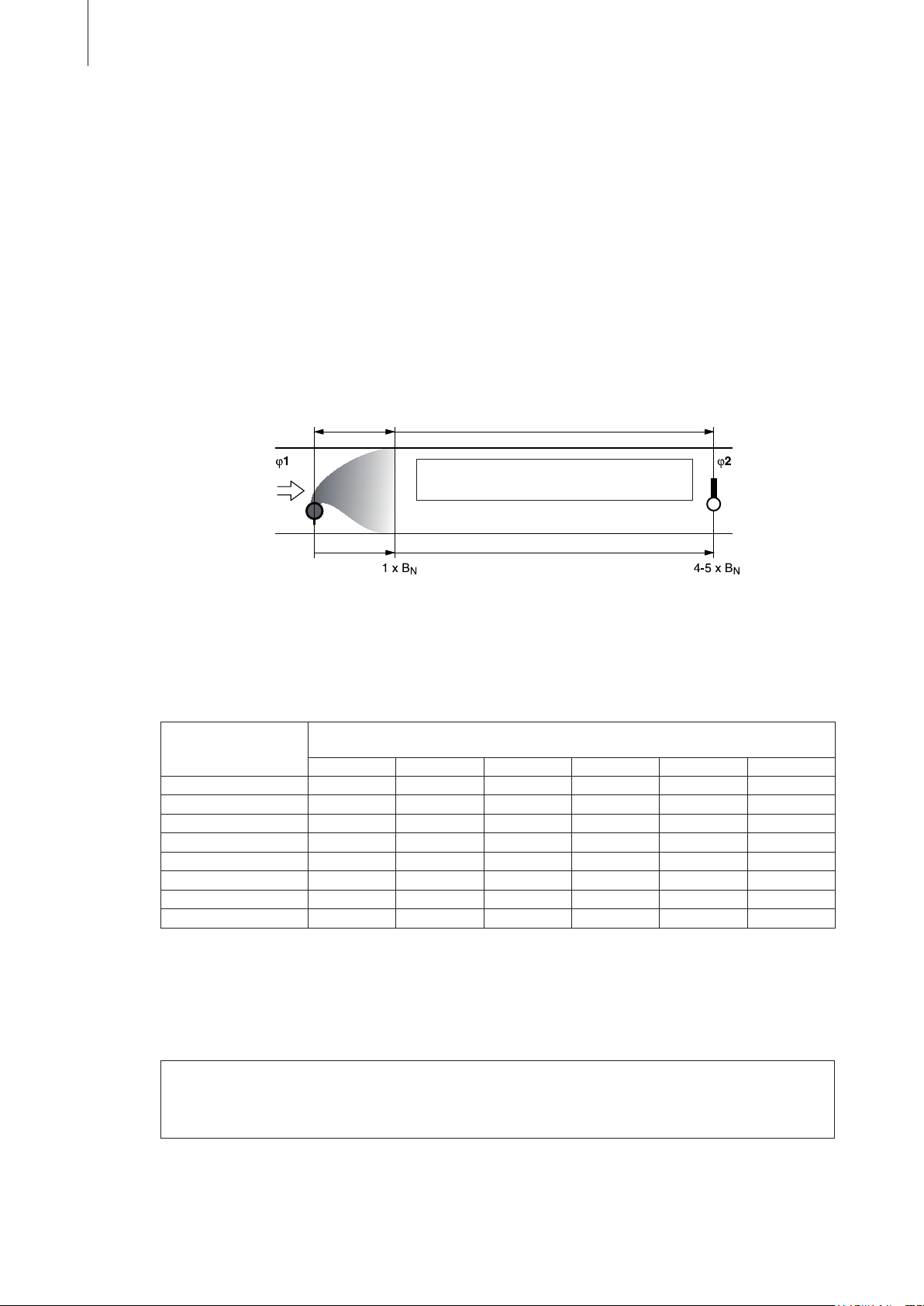
Calculating the humidification distance
The water vapor, emitting from the steam distribution pipes, requires a certain distance to be absorbed
by the ambient air so that it is no longer visible as steam. This distance is referred to as humidification
distance “BN” and serves as a basis for the determination of the minimum distances from the
upstream components in the system.
Humidification
distance B
N
φ 1: Incoming air humidity before humidification
φ 2: Air humidity after humidification
Expansion- and mixing zone
The calculation of the humidification distance “BN” is dependent on several factors. For a rough estimation of the humidification distance “BN”, the following table is useful. Recommended standard
values listed in this table are based on a supply-air temperature range of 15°C to 30°C. The values
given in bold print only apply to steam distribution pipes 81-.., the values in brackets apply to
the OptiSorp steam distribution system.
Input humidity
φ1 in %rh
40 50 60 70 80 90
5 0.9
10 0.8
20 0.7
30 0.5 (0.10) 0.8 (0.17) 1.0 (0.25) 1.4 (0.36) 1.9 (0.52) 2.9 (0.88)
40 – 0.5
50 – – 0.5
60 – – – 0.7
70 – – – – 0.8
(0.22) 1.1 (0.28) 1.4 (0.36) 1.8 (0.48) 2.3 (0.66) 3.5 (1.08)
(0.20) 1.0 (0.26) 1.3 (0.34) 1.7 (0.45) 2.2 (0.64) 3.4 (1.04)
(0.16) 0.9 (0.22) 1.2 (0.30) 1.5 (0.41) 2.1 (0.58) 3.2 (0.96)
(0.11) 0.8 (0.20) 1.2 (0.30) 1.7 (0.45) 2.7 (0.79)
of humidification distance B
Length
Output humidity φ2 in %rh
(0.13) 1.0 (0.24) 1.5 (0.38) 2.4 (0.69)
in m
N
(0.16) 1.2 (0.30) 2.1 (0.58)
(0.20) 1.7 (0.45)
For duct widths <600 mm the humidification distance for the OptiSorp system increases by approx. 50%
φ1 in %rh: Relative supply air humidity prior to humidification at the lowest supply air temperature
φ2 in %rh: Relative supply air humidity after the steam distribution pipe at maximum capacity
Example
given:
φ1= 30 %rh, φ2= 70 %rh
humidification distance B
: 1.4 m (0.36 m for steam distribution system OptiSorp)
N
Note: If the humidification distance has to be reduced for technical reasons, the amount of steam per
steam outlet must be divided between two steam distribution pipes or the steam distribution system
OptiSorp must be used. If this is the case, contact your Condair supplier.
Page 25
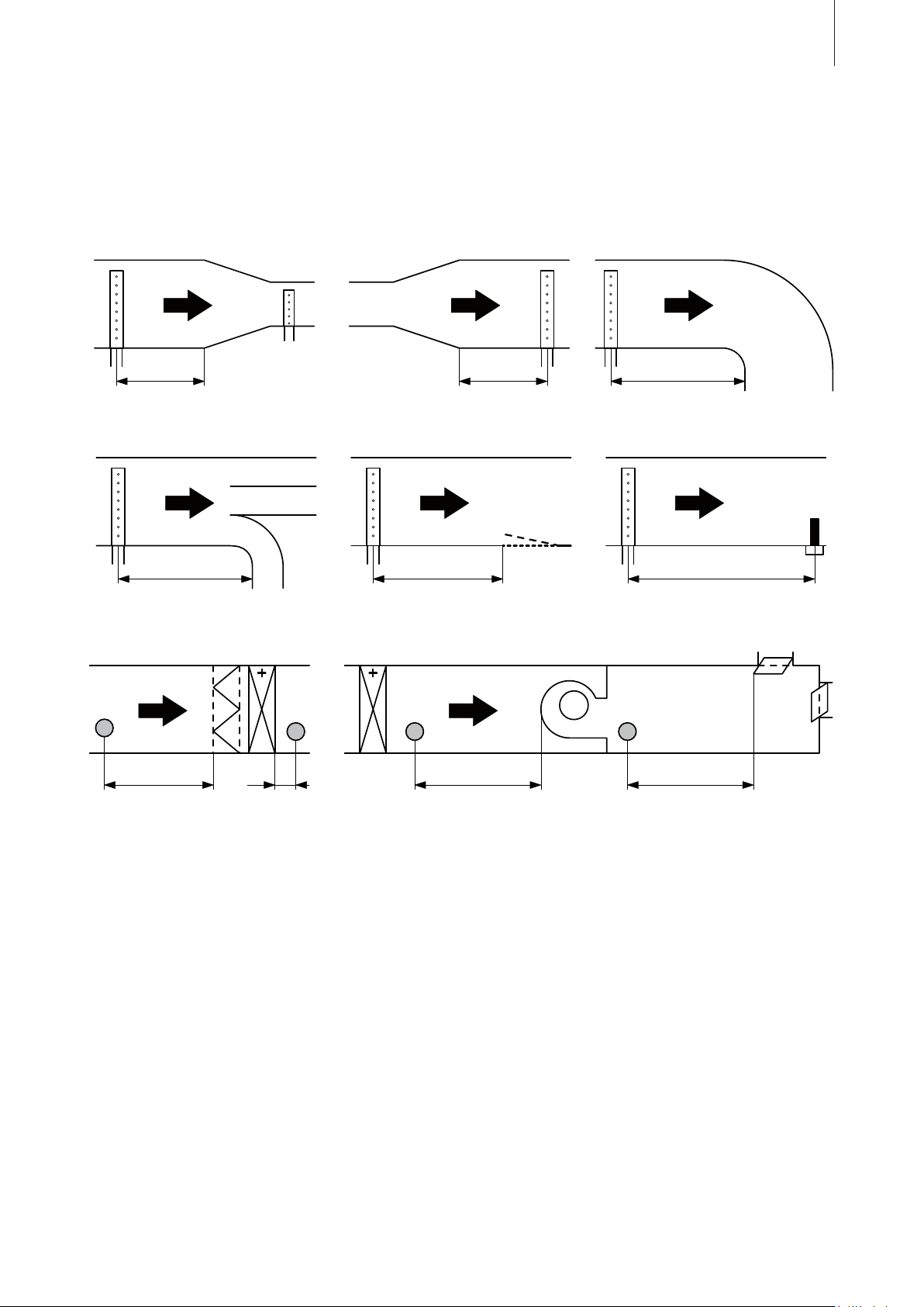
Minimum distances to be observed
0.5 x B
N
B
N
0.5 x B
N
B
N
B
N
5 x B
N
B
N
B
N
1.5 x B
N
*
To prevent the water vapor, that is emitting from the steam distribution pipe, from condensing on
downstream system components, a minimum distance to the steam distribution pipe must be observed
(depends on the humidification distance “BN”).
25
before/after
constriction after expansion before bend
before branch before diffuser before control/temperature sensor
before/after filter/register before/after fan, zone exit
* 2,5 x B
5 cm
before submicron particle filter
N
Installation notes and dimensions
The steam distribution pipes are designed for either horizontal installation (on the duct wall) or, with
accessories, for vertical installation (in the duct floor). The outlet orifices should always point upwards
and at right angles to the airflow.
If possible, the steam distribution pipes should be installed on the pressure side of the duct (max.
duct pressure 1700 Pa). If the steam distribution pipes are installed on the suction side of the duct,
the maximum vacuum must not exceed 800 Pa.
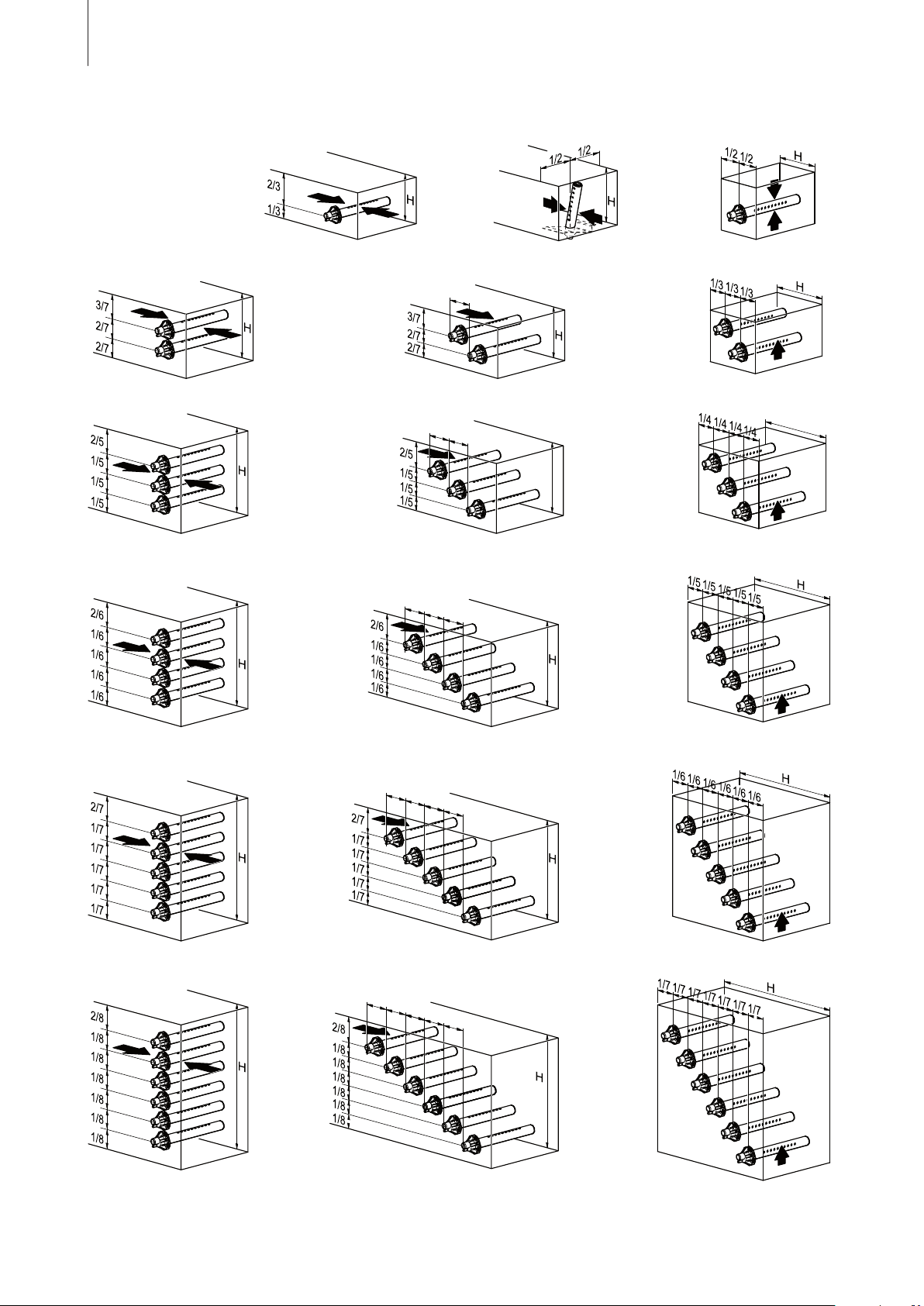
Select a location for the installation, tailored to suit your duct (see the following illustrations) and
position the steam distribution pipes in the duct so that a uniform distribution of steam is achieved.
Page 26
26
H
H
g
min
h
min
g
min
g
min
g
min
g
min
g
min
g
min
g
min
g
min
g
min
g
min
g
min
g
min
g
min
g
min
g min.= 100 mm
h min.= 85 mm
In positioning the steam distribution pipes, the following dimensions should be observed:
H min.= 250 mm H ≥400 mm H
min.= 200 mm
H min.= 400 mm H min.= 350 mm H min.= 300 mm
H min.= 600 mm H min.= 500 mm H min.= 400 mm
H min.= 720 mm H min.= 600 mm H min.= 500 mm
H min.= 840 mm H min.= 700 mm H min.= 600 mm
H min.= 960 mm H min.= 800 mm H min.= 700 mm
Page 27
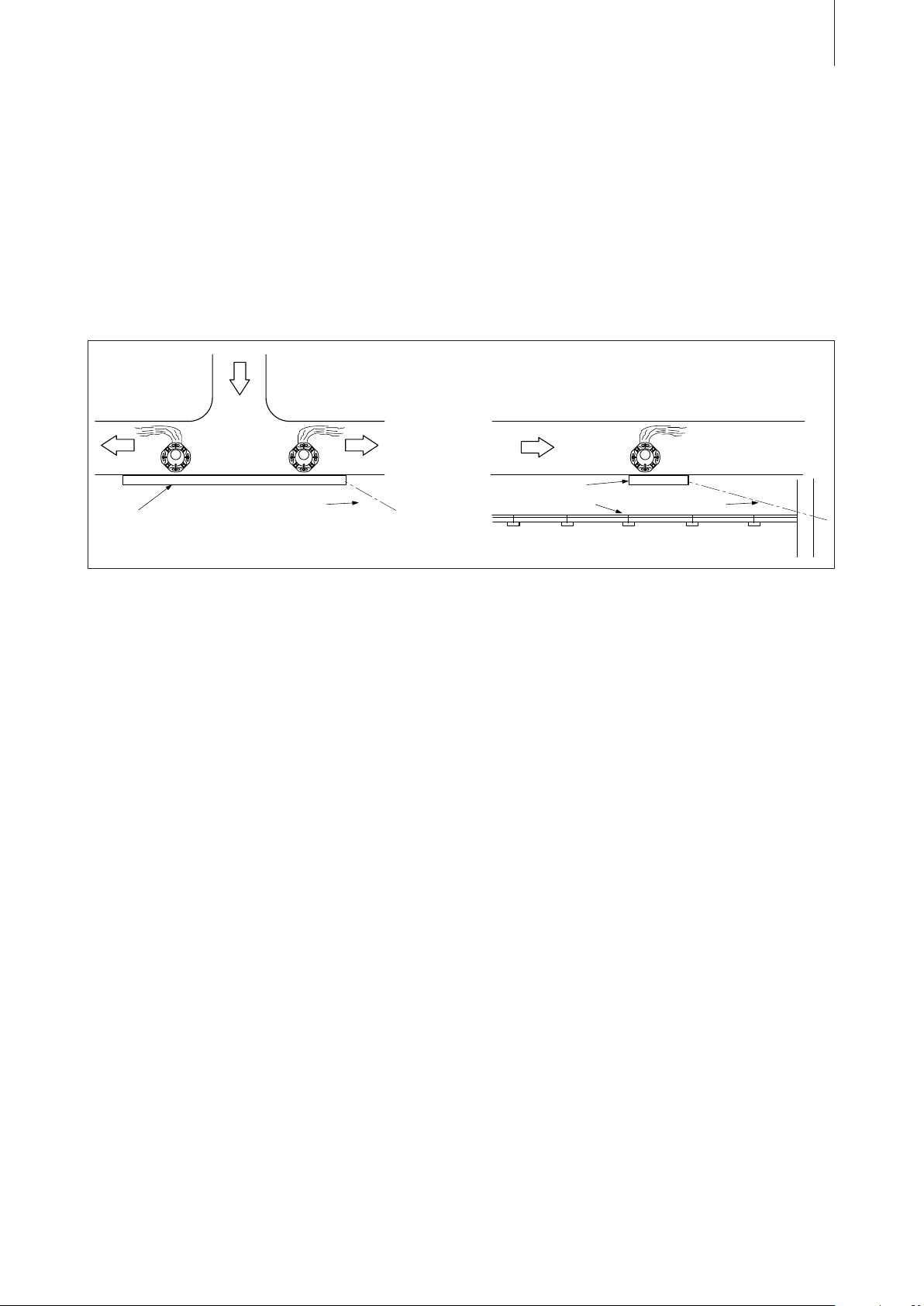
Drain pan
Note: When locating the OptiSorp steam distribution system please note the instructions in the
separate documentation for this product.
Guidelines for dimensioning the ventilation ducts
– To facilitate the installation of the steam distribution pipes and for control purposes, a sufficiently
sized control opening should be planned.
– Within the range of the humidification distance, the ventilation duct should be waterproofed.
– Low temperature ducts below 15°C, shallow ducts, or branch ducts might require the use of a
field supplied condensate drain pan below the steam distributor (see figure below).
Branch duct
Shallow duct
Drain pan
to drain
Ceiling
to
drain
27
– Air ducts passing through cold rooms should be insulated to prevent the humidified air from con
densing along the duct wall.
– Poor airflow conditions within the air duct (e.g. caused by obstacles, tight bends, etc.) can lead
to condensation of the humidified air.
– Steam distribution pipes must not be mounted to round ducts.
– Exercise extreme caution when installing in fiberglass or internally lined ducts. If necessary, re
10-15 cm of the lining where the steam is being introduced.
move
If you have questions relating to the dimensioning of ventilation ducts in combination with Condair
steam humidifiers, contact your Condair supplier.
Installing the steam distribution pipes/OptiSorp steam distribution system
Detailed information on the installation of steam distribution pipes and OptiSorp steam distribution
system can be found in the separate “Mounting Instructions” for this products.
-
-
Page 28
28
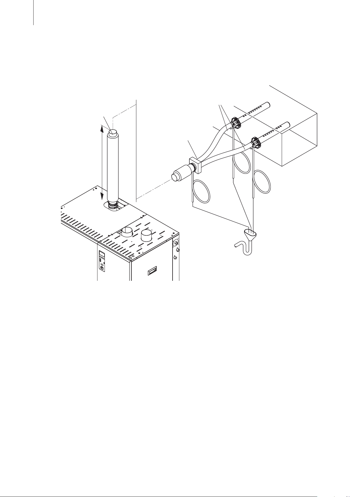
5.3.2 Installing the main steam pipe
The steam pipe between the steam outlet of the unit and the steam hose adapter (main steam pipe)
must be made with solid piping.
Main steam pipe
length 6 m)
(max.
min. 1 m
steam hoses
(max.
steam hose adapter
(accessory “SA..”)
length 4 m)
The following notes must be observed:
– The internal diameter of the steam outlet on the unit must be maintained over the entire length
of the main steam piping.
– The maximum length of the main steam pipe is 6 m.
Important! Allowance must be made for a pressure loss of 10 mm water column (approx.
100 Pa) per meter length or per 90° bend.
– The minimum bend radius for solid pipes is 4-5 x internal diameter. 90° bends should be
avoided. Wherever possible, pipe bends with large radius should be used (e.g. produced using
a pipe bending machine, or constructed from a pair of 45° bends). This reduces the performance
loss due to the formation of condensate, and in addition, the static pressure in the steam line.
– Use Cu pipe (for operation with untreated drinking water only) or stainless steel pipe (min. DIN
1.4301) exclusively.
– To minimize the condensate formation (= loss), the steam pipes must be insulated over the entire
length of the piping.
– Connection of the steam pipe to the steam outlet on the unit and the connection on the steam
hose adapter is effected by means of short lengths of steam hose secured with hose clamps.
– At spots where condensate could accumulate inside the pipe a condensate drain with siphon
(min. hose bend Ø200 mm) must be mounted.
Page 29
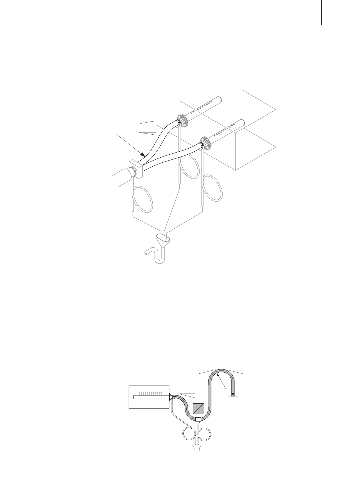
5.3.3 Installing the steam hoses between steam hose adapter
and steam distributors
Important! Use original Condair steam hose exclusively. Other types of steam hoses can cause
undesired operational malfunctions.
The following notes must be observed:
min. 20 %
29
R min. 300 mm
min. 5 %
max. 4 m
– Lead the steam hose with an upslope of at least 20% or with a minimum downslope of 5% to
the steam distribution pipe.
– The steam hose should be kept as short as possible (ideally 2 m, max. 4 m) while observing the
minimum bend radius of 300 mm. Important! Allowance
must be made for a pressure loss
of 10 mm water column (approx. 100 Pa) per meter steam hose.
– Reductions in the cross section such as kinks should be avoided throughout the entire length of
the hose. The installation of a stop cock in the steam hose is not permissible.
– Steam hoses must be prevented from sagging (condensate pockets); if necessary, support with
pipe clamps, rails or wall brackets. If sagging can not be prevented (e.g. when passing by obstacles)
a condensate drain with siphon (min. hose bend Ø200 mm) must be mounted at the lowest
point of the steam hose (see following illustration).
min. 5 %
min. 20 %
Rmin.
max. 4 m
min. 20 %
300 mm
– Important! When deciding on the length and layout of the hose, it should be noted that the steam
hose may become somewhat shorter with progressive ageing.
Page 30
30
Securing the hose
The steam hose must be secured to the steam distribution pipe and humidifier steam outlet by means
of hose clamps.
Steam line with fixed piping
For steam lines with fixed piping, the same instructions apply to the laying of the piping as already
described. The following additional notes should be observed:
– The minimum internal diameter of 45 mm should be applied over the whole length of the piping.
– Use exclusively Cu pipe (for operation with untreated drinking water only) or stainless steel (min.
DIN 1.4301).
– To minimize the condensate formation (=loss), the steam pipes must be insulated.
– The minimum bend radius for solid pipes is 4-5 x internal diameter
bends should be avoided. Wherever possible, tube bends with large radii should be used (e.g.
90°
.
produced using a tube bending machine, or constructed from a pair of 45° bends). This reduces
the performance loss due to the formation of condensate, and in addition, the static pressure in
the steam line.
– Important! Allowance must be made for a pressure loss of 10 mm water column (approx.
100 Pa) per meter length or per 90° bend.
– Connection of the steam pipes to the steam distribution pipe and steam humidifier is effected by
means of short lengths of steam hose secured with hose clamps.
5.3.4 Installing the condensate hoses
Important! Use
ational malfunctions.
original Condair condensate hose exclusively. Other types of hoses can cause oper-
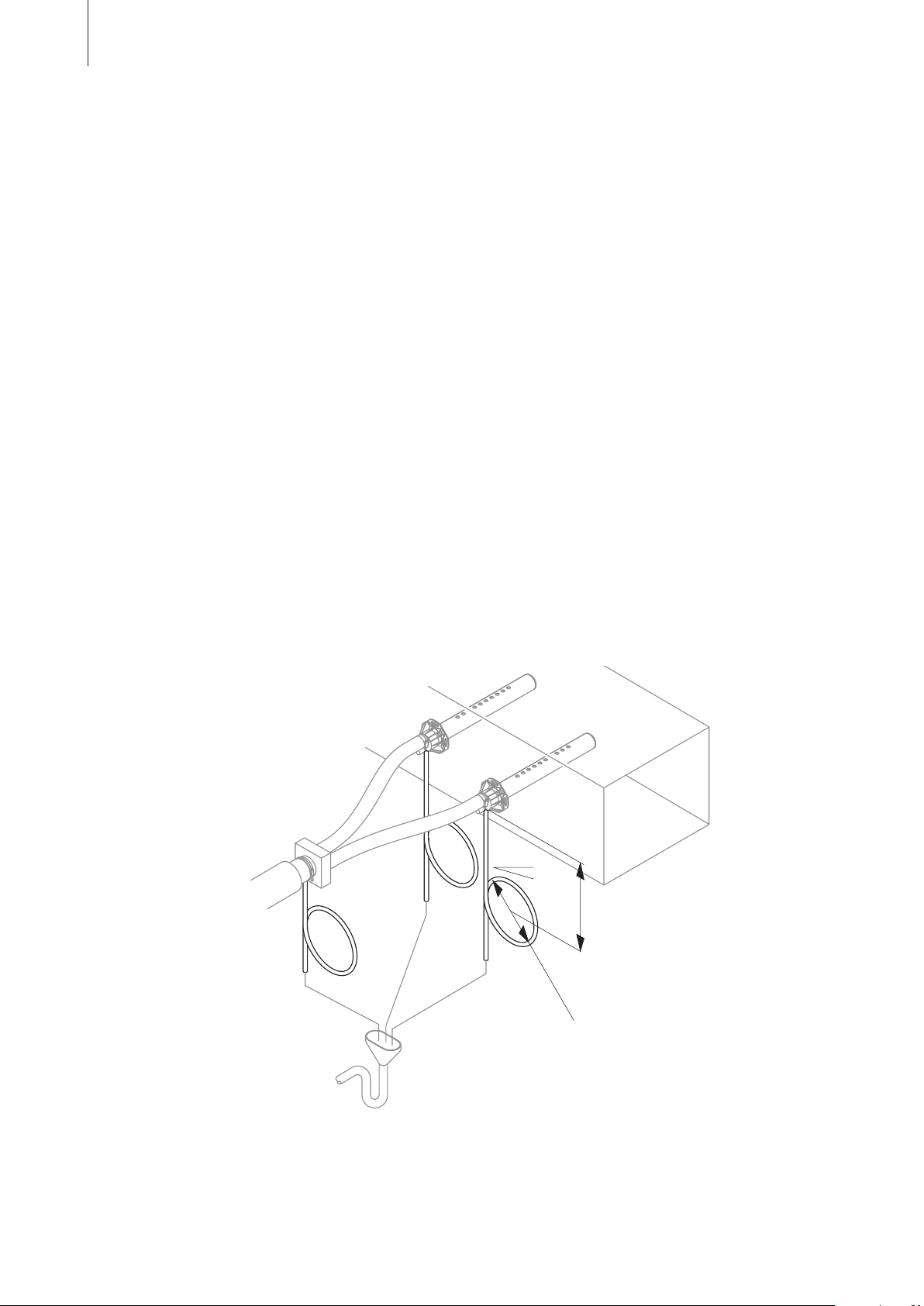
min. 20 %
min. 300 mm
Ø min. 200 mm
The individual condensate hoses of the main steam pipe (if present), the steam hose adapter (if
present) and the steam distribution pipes must be led down with a minimum downslope of 20 %
via a siphon (min. hose bend ø200 mm) into a discharge funnel.
Important! Before putting the unit into operation, the siphon of the condensate hose must be filled
with water.
Page 31
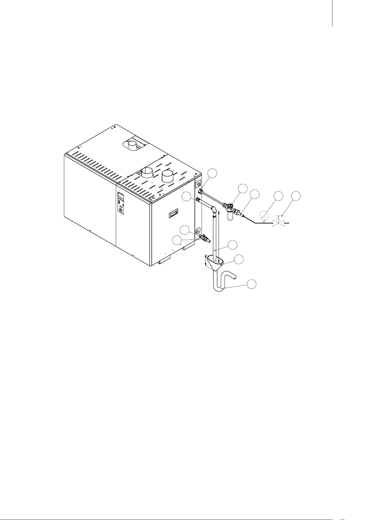
5.4 Water installation
9
6
7
8
10
11
1
2
3
4 5
5.4.1 Performing the water installation
Overview water installation
31
min. 50 cm
min. 15 cm
1 Filling water connection BSP 3/4" (outside thread)
2 Filter valve (accessory “Z261”)
3 Filling water supply line (min. inner Ø: 12 mm)
4 Manometer (installation recommended, building side)
5 Pressure reducing valve (compulsory for water pressures >8 bar, building side)
6 Water drain connection 3/4" (Ø19 mm)
7 Drain line, building side (min. inner Ø: 45 mm, min. 50 cm directed vertically downwards)
8 Funnel (building side, min. height 15 cm)
9 Siphon (min. inner Ø: >45 mm, building side)
10 Auxiliary water drain connection NPT 1/2" (inside thread)
11 Shut-off valve (installation recommended, building side)
Page 32

32
Water supply
The water supply pipe is to be connected via the filter valve (accessory “Z261”), to the connection
on the unit (see foregoing illustration). The filter valve should be installed as close to the humidifier
as possible.
Note: Instead of the filter valve, a shut-off valve and a water filter 5 µm ( (both
essential) can be
used.
The following specifications must be observed:
– Connections on unit: BSP 3/4" (outside thread)
– Min. inner diameter of supply line: 12 mm
– Admissible mains pressure 3.0 to 8.0 bar (hammer-free system)
For mains pressures >8 bar, connection must be made via pressure reducing valve (adjusted to
3.0 bar). For mains pressures <3.0 bar please contact your Condair supplier.
– Supply rate: 10 l/min
– Admissible supply temperature: 1…30 °C
– Notes
on water quality:
– For the water supply of the Condair GS, use exclusively untreated drinking water or fully
demineralized water.
Note:
The use of fully demineralized water reduces the maintenance and the cleaning of the
water tank to a minimum.
– The use of additives such
as corrosion inhibitors, disinfectants, etc. is not allowed, since
these additives may endanger health and affect proper operation.
– If the Condair GS shall be operated with softened or partly softened water, please contact your
Condair supplier.
– The connection material must be pressure-proof and certified for use in drinking water supply
systems.
CAUTION!
Fully demineralized water is aggressive. When making connections to a fully demineralized water
system, use exclusively plastic or stainless steel installation materials (min. DIN 1.4301).
– Important! Before connecting the water line to the unit, the line must be flushed thoroughly.
Page 33

Water drain
The drain line should be connected to the unit drain connection using a hose coupling. The drain
line should drop vertically down for a minimum of 50 cm and into an open drain funnel (min. height
15 cm). The drain line is then connected via a siphon to the building drain line. The minimum internal
diameter of 45 mm must be maintained over the full length of the building drain line. Make sure that
the drain line is correctly attached and easily accessible for the purpose of inspection and cleaning.
The following connection data should be observed:
– Connection on unit (hose connection): 3/4" (Ø19 mm)
CAUTION!
Use only temperature-resistant installation materials!
When using fully demineralized water, only stainless steel (min. DIN 1.4301) or chemically-re-
plastic (e.g. Polypropylene) connection components must be used.
sistant
– Drainage capacity: approx. 20 l/min
– Min. inner diameter of the building drain line: 45 mm
– Min. downslope after siphon: 10 %
Note: It is not permissible to curve the drain pipe upwards, because this can lead to the collection
of deposits at the lowest point in the pipe and to the blockage of the pipe.
33
Page 34
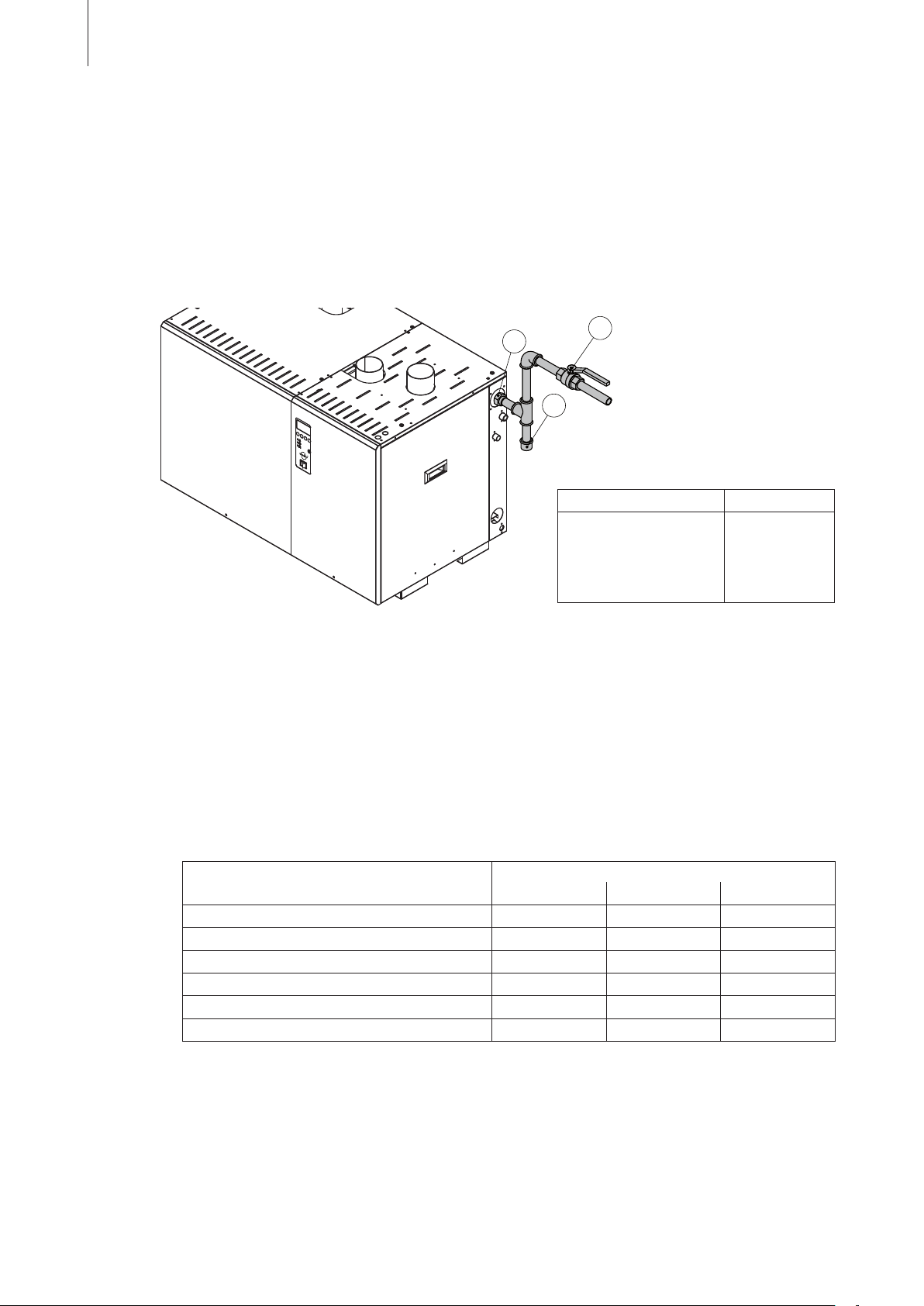
34
3
1
2
5.5 Gas installation
All installation work must be carried out in accordance with the applicable local building and in
stallation
regulations.
5.5.1 Performing the gas installation
Overview Gas installation
-
1 Gas supply connection
Model Connection
GS 40 BSP 1/2"
GS 80 BSP 3/4"
GS 120 and GS 160 BSP 1"
GS 200 and GS 240 BSP 1 1/4"
2 Gas shut-off valve (building side)
3 Sediment trap (Installation - building side -
essential in the case of the use of steel
gas pipes)
Installation notes
The gas supply pipe must be connected to the connection on the unit via a shut-off valve (essential
requirement), which is installed in the immediate vicinity of the unit. When steel gas pipes are in use,
it is essential that a sediment separator be fitted between the shut-off valve and the unit connection.
The following connection data must be adhered to:
– Permissible gas operating pressure:
Gas Operating pressure (mbar)
Nominal Min Max
Natural
Natural
Natural gas HS G25.1 25 20 3
Natural gas Lw G27 20 17.5 2
Natural gas Ls GZ350 13 10.5 16
Propane
–
The connection material used must be pressure tested and approved for gas installations.
gas H, E, E(S) G20 20 17 25
gas L, ELL G25 25 20 3
gas P G31 37 or 50 25 57.5
0
0
3
– Do not use teflon tape on gas line pipe threads. A flexible sealant suitable for use with Natural
Gas and Propane Gas is recommended.
– Plan gas supply piping so it will not interfere with removal of gas valves or blower assemblies and
front or side service doors.
Page 35

5.5.2 Leak testing
After completion of the installation work, the whole gas line must be tested to a maximum pressure
of 40 mbar (4.0 kPa) for natural gas or 150 mbar (15 kPa) for propane and checked for leaks us-
ing a commercially available soap solution. The bubbles indicate leaks. All leaks must be eliminated
before the humidifier is put into operation.
DANGER!
Never use an open flame to check for leaks. The presence of any leakage is a source of danger
to persons and to property, due to the possibility of fire and explosion.
If the gas circuit must be tested to a pressure of over 150 mbar (15 kPa), the gas supply pipe must
be removed from the unit connection. After the test, the gas line must be depressurized before it is
reconnected to the unit.
CAUTION!
Non-observance of the above instruction can lead to damage to the gas pressure regulating valve.
Gas pressure valves overloaded due to high pressure are not covered by the manufacturer‘s
guarantee.
35
5.5.3 Conversion instructions for operating the humidifier with another type of gas
Ex works the appliance is equipped to operate on one type of gas. To convert an appliance for operation on another type of gas, follow the directions below (see also illustration on the following page).
Important: The conversion shall be carried out by a manufacturer’s authorized representative
or person trained and licenced for such activities, in accordance with the requirements of the
manufacturer or local authorities having jurisdiction in the area of installation.
1. Disconnect the humidifier from the electrical power supply and take precautions against inadvert-
ent
switching on.
2. Turn off gas supply to appliance and secure it against inadvertent opening.
3. Undo the screw(s) (phillips screwdriver) and remove the right side panel(s).
4. Disconnect the hose(s) from the inlet elbow (note the layout). Then, loosen the hose clamp and
remove the inlet elbow.
5. Undo the coupling of the corresponding flexible gas pipe and disconnect gas pipe from the gas
pressure regulating valve.
6. Disconnect electrical cables to the gas pressure regulating valve and the air pressure switch
(note assignment before removal).
7. Undo the two screws that mount the venturi manifold to the combustion air blower, then lift up
the manifold together with the gas pressure regulating valve.
8. Undo the four screws and remove the gas pipe connection of the gas pressure regulating
valve.
9. Undo the three screws of the air pressure switch support and remove the pressure switch as
sembly
10. Check the cork gasket and the O-ring in the gas pipe connection for damage and replace if
necessary.
from the gas pressure regulating valve.
-
Page 36
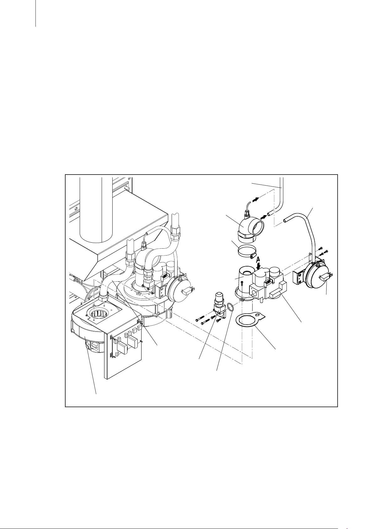
36
11. Attach the gas pipe connection (with mounted O-ring) and the pressure switch assembly to the
gas pressure regulating valve supplied (comes with venturi manifold attached).
Warning! Make sure the gas type indicated on the label of the venturi manifold corresponds to
the gas you are using. Do not change the setting of sealed adjustment screw “A”.
12. Fix the new venturi manifold (don’t forget the cork gasket) together with the gas pressure regulat-
ing valve with the two screws to the combustion air blower.
13. Reconnect the flexible gas pipe to the gas pressure regulating valve and tighten the coupling.
14. Fix the inlet elbow with the hose clamp to the venturi manifold.
15. Reconnect the hose from the air pressure switch and if present from the air inlet manifold (on
RS units only) to the inlet elbow.
16. Reconnect the electrical cables to the gas pressure regulating valve and the air pressure
switch.
On multiple burner units repeat steps 4 to 16 for each gas valve assembly.
17.
Hose to air inlet manifold
(RS units only)
Hose to
pressure switch
Inlet elbow
Combustion air blower
Flexible gas pipe
gas pipe connection
Hose clamp
Venturi manifold
Pressure switch
Gas pressure
regulating valve
Cork gasket
O-ring
18. Carry out a leakage test (Refer to instructions in 5.5.2).
19. Turn power to unit back on and initiate a test fire sequence to check for proper ignition charac-
teristics.
20.
If tests are acceptable, affix appropriate conversion label to data plate. Replace door panel and
fix it with screw. Then, return unit to normal operation.
21. Conversion is now complete.
Page 37
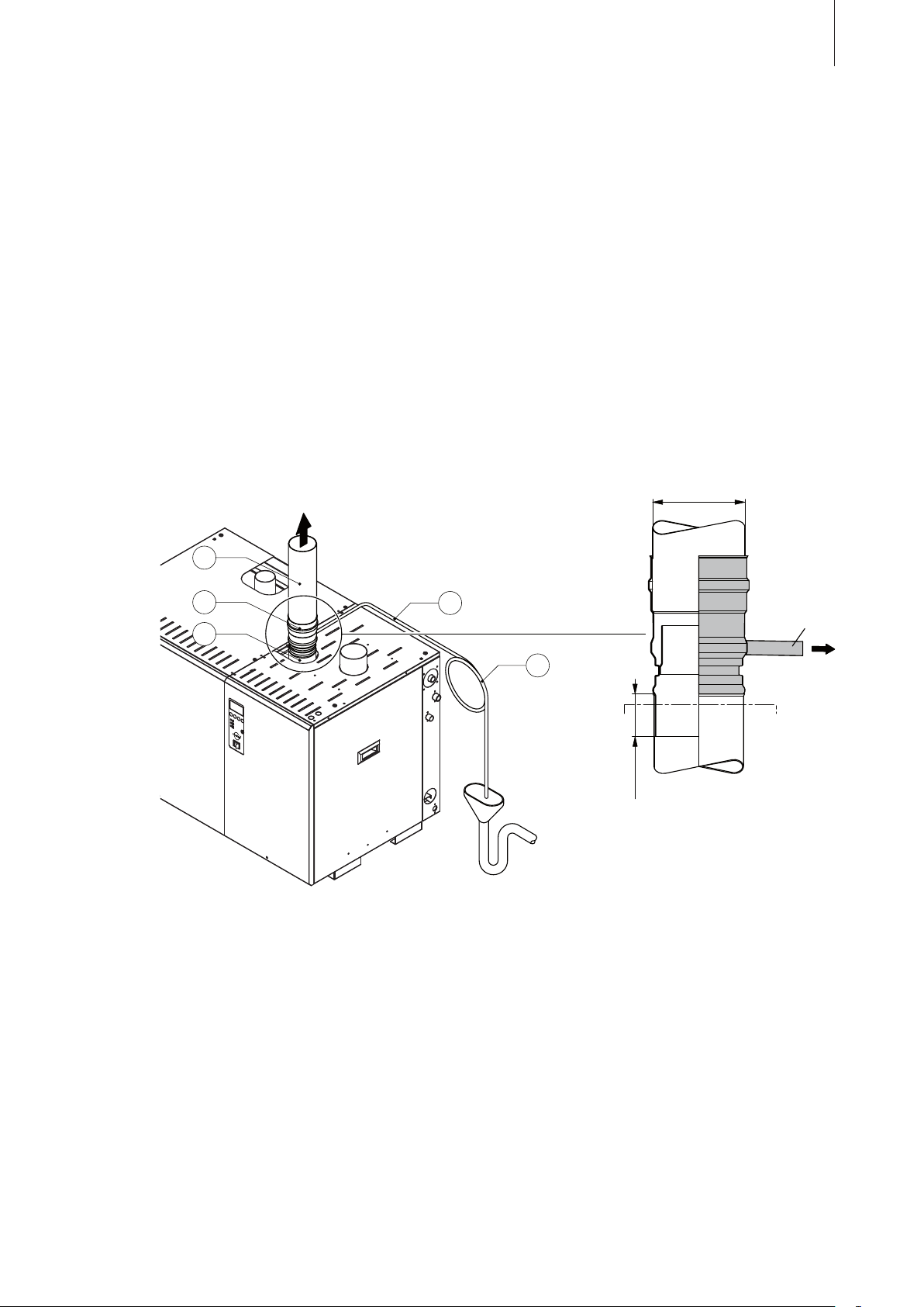
5.6 Flue gas installation
D
A
3
2
1
5
4
Important: Since the regulations for the installation of flueing systems differ from country to country,
the relevant local regulations must be adhered to without reservation.
In any case, please consult your Condair representative. This applies in particular to the room
air-independent steam air humidifiers (RS units).
Please note that flueing must be designed for overpressure or underpressure, depending on local
regulations.
All work concerning the flue pipe installation must be performed only by adequately qualified personnel.
Ascertaining the qualifications is the customers responsibility.
5.6.1 Performing flue gas installation
Overview
37
1 Flue gas connection on the unit
D
GS 40 ø80 mm
GS 80 ø100 mm
GS 120 / GS 160 ø130 mm
GS 200 / GS 240 ø160 mm
A
ø15 mm
max. 40 mm
– GS 40: ø76 mm (3")
– GS 80: ø101 mm (4")
– GS 120/GS 160: ø127 mm (5")
– GS 200/GS 240: ø152 mm (6")
2 Flue gas adapter with condensate drain (accessory “FA...”)
– GS 40: FA40 (D
– GS 80: FA80 (DA= 100 mm)
– GS 120/GS 160: FA120/160 (DA= 130 mm)
= 80 mm)
A
– GS 200/GS 240: FA200/240 (DA= 160 mm)
3 Flue gas pipe (building side)
4 Condensate drain (building side)
5 Siphon (min. diameter 300 mm, building side)
Page 38
38
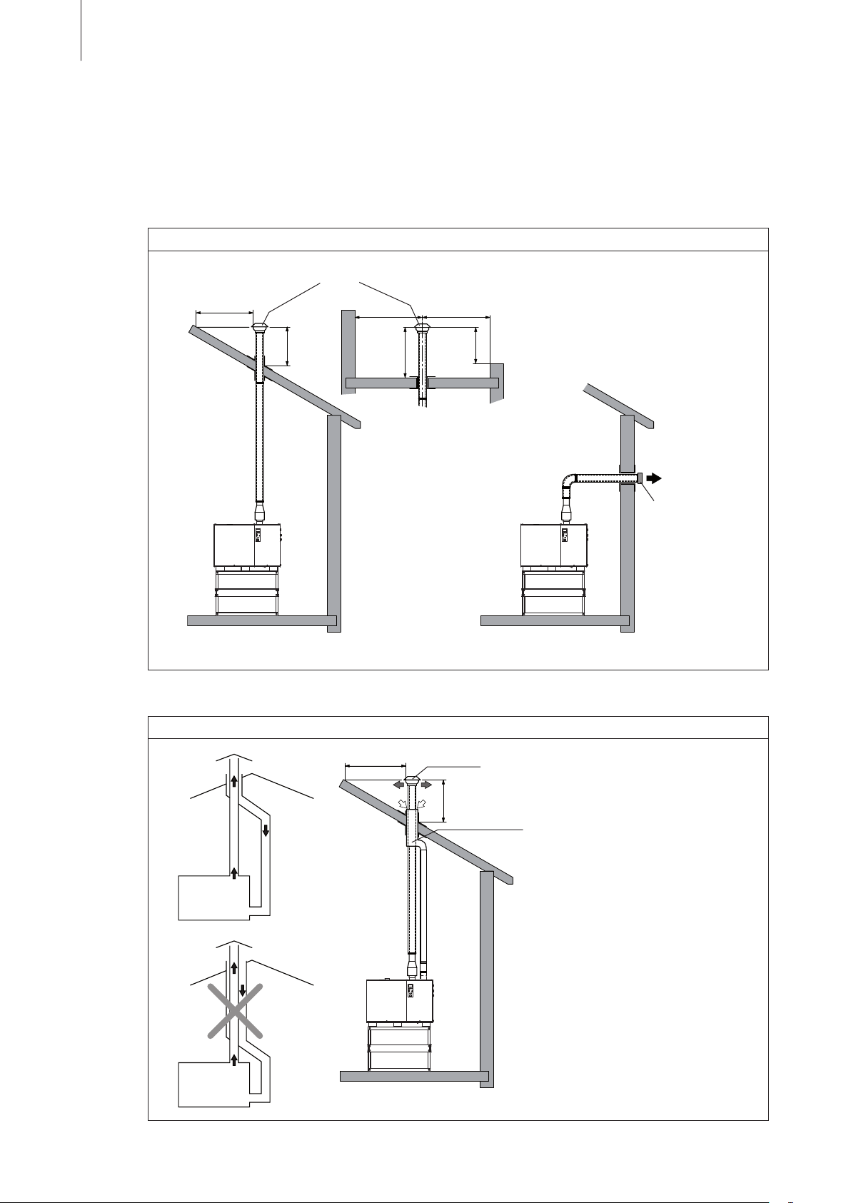
Flue arrangement
There are different types of applicable flue systems for the Condair GS depending on the unit type
(room air-dependent or room air independent units). The following flue gas diagrams are for guidance
only, and must be read in accordance with the local country codes for flue gas systems.
Applicable flue systems for room air-dependent units
Type B23
Rain cap (by client)
min. 1.5m
min.1m
max. flue length for type B23 flue systems: 30 m (see installation notes)
≤ 2.5m> 2.5m
≥ 1m
≥ 1m
Applicable flue systems for room air-independent units – RS units
flue gas terminal
(according local
regulations)
correct
not
correct
Type C33
min. 1.5m
min.1m
max. flue length for type C33 flue systems: 15 m (see installation notes)
Rain cap (by client)
Reference part number for
flue terminal/adapter from
Muelink&Grol
GS 40: 82420
GS 80: 82421
GS 120/GS 160: 82422
GS 200/GS 240: 82423
Page 39

min. 1.5m
39
Type C53
Rain cap (by client)
> 2.5 m ≤ 2.5 m
min.1m
≥ 1m
≥ 1m
air inlet terminal
(according local regulations)
flue gas and
inlet terminals
air
(according local
regulations)
max. flue length for type C53 flue systems: 21 m (see installation notes)
Type C63x
Note: Where local regulations permit, the RS units can be installed as C63x
appliances. As a C63x appliance, the Condair GS can be connected to a
separately approved and maketed system for the supply of combustion air
and discharge of flue gases. For such applications, refer to the applicable
local regulations and the separate Installation Instructions “Installation as
a C6 appliance” available from your Condair dealer.
min. 1.2 m
Page 40

40
General installation notes
The following instruction notes must be observed:
– Flue gas specifications: ---> see table in chapter 10.2
– The flue gas temperature during normal application and when the maintenance schedule is
fulfilled is between 160 - 180 °C. If the unit is not maintained properly the flue gas temperature
could increase. In this case the temperature switch would shut down the unit if the temperature
exceeds 200 °C for safety reasons.
– Use exclusively corrosion free installation and sealing materials tested and approved for flue gas
systems.
All connections of the flue gas pipe must be sealed with high temperature RTV silicone rated for
–
at least 250 °C.
– Select a suitable piping arrangement for the discharge of flue gases from the building.
– The minimum internal diameter must be observed over the entire length of the flue gas pipe.
– GS 40: ø76 mm (3")
– GS 80: ø101 mm (4")
– GS 120/GS 160: ø127 mm (5")
– GS 200/GS 240: ø152 mm (6")
– Horizontal pipe sections should have a minimum upward slope of 21 mm/m and should be sup
every 1.5 m and additionally supported at every pipe bend.
ported
– For any flue lengths over 7 m long, use insulated pipes.
– When the flue pipe is lead through nearby rooms the pipe must be equipped with an F90-type
insulation.
–
Provide a fire-proof screen or barrier (at a minimum distance of 50 mm to flue gas pipe) to prevent
personal injury in areas where inadvertent personnel contact with flue pipe can occur or where
heat-sensitive products are stored.
– Secure the flue pipe (e.g. by means of beading the pipe, see overview) to prevent it from slipping
into the flue connector of the unit.
– A condensate discharge point should be installed at an appropriate position in the GS humidifier
flue gas system (see overview). A siphon with a minimum 300 mm head of water must be installed
in the condensate discharge line, so that no flue gases can escape via the discharge pipe.
Before operating the humidifier, make sure that the siphon in the condensate discharge is filled
with water and the condensate outlet is in accordance with the applicable local regulations for
sanitary installations.
Flueing with overpressure
When flueing with overpressure the maximum admissible length of the flue pipe equals 30 meters for
room air-dependent units and 21 meters for room air-independent RS unit (assuming same diameter
as connector on Condair GS) where each 90° elbow is equal to 3 m and each 45° elbow is equal to
1.5 m of straight pipe. Three elbows outside the humidifier casing is a recommended maximum for
flueing systems.
-
We recommend 30 m or 21 m respectively flue length maximum to ensure that output is maintained.
For lengths over 30 m or 21 m respectively, please consult your Condair supplier.
Page 41

Flueing with underpressure
If local regulations require flueing with underpressure, the underpressure must be within -0.2 and
-0.62 mbar. The applicable local regulations for the layout of flue gas pipes for underpressure must
be observed and complied with.
Additional requirements when flueing through a sidewall
Attention! Some countries prohibit leading the flue pipe through a side wall. Observe local regulations
and contact the local authorities and/or the chimney-sweep.
Position the humidifier as near as possible to the wall through which the flue pipe is to be taken.
Locate the flue terminal at least 1 m above any forced air inlet located within 3 m; or at least 1 m
below, 1 m horizontally from, or 0.5 m above any door, window, or gravity air inlet into any building.
41
A minimum horizontal clearance of 1 m from electric meters, gas meters, regulator and relief equip
ment
is required.
Locate the flue terminal at least 2.5 m above grade when it is adjacent to public walkways.
Locate the bottom of the flue terminal at least 45 cm above grade or ground, or normally expected
snow accumulation level. The snow level may be higher on walls exposed to prevailing winds.
Avoid areas where local experience indicates that condensate drippage may cause problems such
as above planters, patios, or over public walkways, or over an area where condensate or vapor could
create a nuisance or hazard, or could be detrimental to the operation of regulators, relief valves, or
other equipment.
Refer to the flue manufacturer’s installation instructions.
Additional requirements for flue gas systems of RS units
The RS units are certified as C33 and C53 appliances. Where local regulations permit, the RS units
can be installed as C6 appliances. For such applications, refer to the separate Installation Instruc
tions
“Installation as a C6 appliance” available from your Condair dealer.
Please observe the following additional requirements for the flue gas installation of RS units:
– Only use installation material in accordance with the local regulations.
– The flue gas pipe and the air inlet pipe must have the same length (min. 2.1 m, max. 21 m (C33:
max. 15 m)).
-
-
– Observe the requirements regarding terminal locations in section 5.7.
Page 42
42
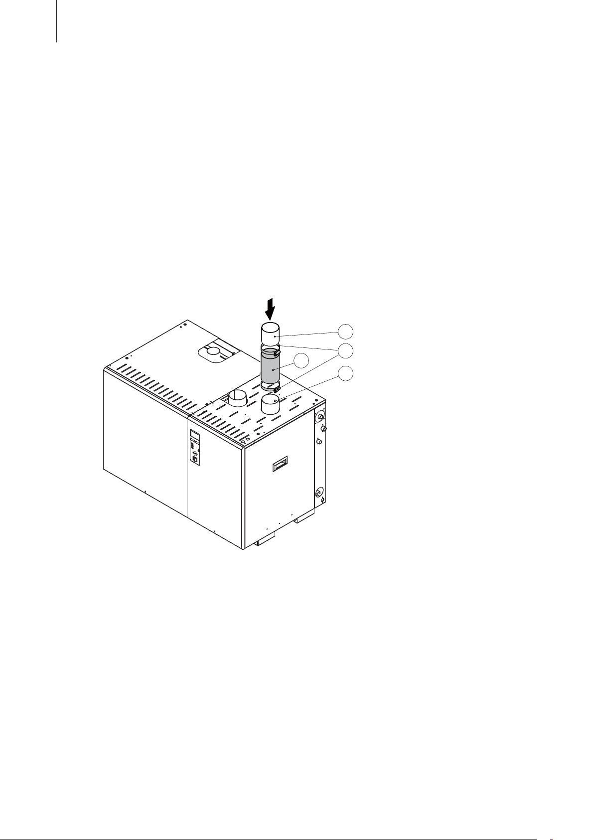
1
2
3
4
5.7 Installation of the air inlet line for room air-independent units (RS units)
Important: Since the regulations for the installation of air supply systems for gasfired appliances differ
from country to country, the relevant local regulations must be adhered to without reservation.
In any case, please consult your Condair representative.
Installation of the air supply line must only be carried out by adequately qualified personnel.
5.7.1 Performing air supply installation
Overview
1 Air supply connection on RS units
– GS 40: ø76 mm (3")
– GS 80: ø101 mm (4")
– GS 120/GS 160: ø127 mm (5")
– GS 200/GS 240: ø152 mm (6")
2 Connection hose (building side)
3 Hose clamps (building side)
4 Air supply line, hose or rigid pipe (building side)
Page 43
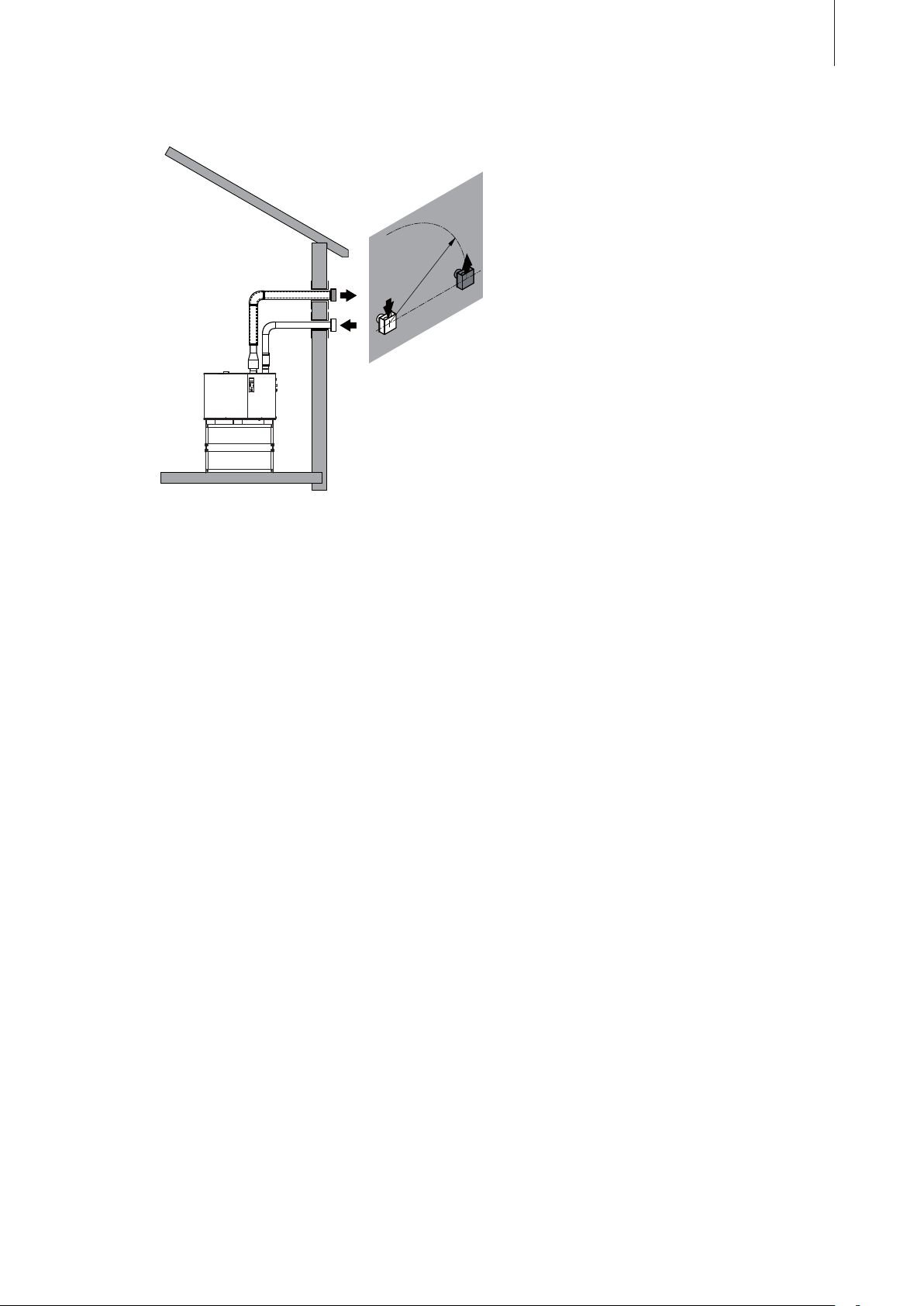
Air supply arrangement
43
min. 1.2 m
Installation notes
– Max. admissible supply air temperature is 30 °C. Make sure the air supply line is not heated up
by the flue gas line.
– The maximum pipe length for the air supply line is equivalent to 21 meters. The minimum diam
(see above) must be maintained over the entire length of the line. In this estimate, each 90°
eter
bend is equal to 3 m of straight pipe length and each 45° bend is equal to 1.5 m of straight pipe
length. Not more than 3 pipe bends must be built into the air supply line.
The air supply line should be approximately as long as the flue gas line and must be supported
at least every 1.5 m of its length and additionally supported at every pipe bend.
– The air supply line can be provided either as a fixed tube or as a hose. The minimum internal
diameter must be observed over the entire length.
– GS 40: ø76 mm (3")
– GS 80: ø101 mm (4")
– GS 120/GS 160: ø127 mm (5")
– GS 200/GS 240: ø152 mm (6")
– All connections on the air supply line must be positively sealed with a silicone sealant to ensure
proper sealing of the air supply line.
– The air supply line must be installed with the supplied air intake wall terminal (see illustration
above and refer to section “Terminal locations”).
– At low temperatures (under 18 °C), water of condensation can form on the outside of the air sup
line. To prevent this, we recommend that air supply lines that are situated in cold rooms are
ply
insulated.
-
-
Page 44

44
Terminal locations
When locating the air intake and the flue gas terminals the following requirements must be ob
served:
All terminal must terminate at an outside location.
–
– Location of air intake and flue gas terminal must comply with all local and national regulations.
– Air intake and flue gas terminal can be installed in different pressure zones.
– Air intake and flue gas terminal cannot be installed on opposite walls of the building.
– A minimum distance of 1.2 m must be maintained between the air intake and the flue gas terminal
to prevent recirculation of flue gases (see figure above).
– When the flue gas or air intake terminal is located less than 2.75 m from the ground or can be
accessed by personnel a guard must be installed at a minimum distance of 50 mm to the terminal
to prevent personal injury.
5.8 Installation of control and monitoring devices
– Install the room humidity sensor and the safety humidistat at the same height as thermostats
and in a location where the measured humidity corresponds to that of the room. Under no circumstances should the humidity sensors be positioned in the vicinity of the air flow from ventilator units or air intake grids. Do not mount humidity sensors on an outer wall, where temperature
fluctuations can affect the control behavior.
-
– Install the duct humidity sensor in a position where the measured humidity corresponds to that
of the room that is being humidified (usually in the duct return circuit). Do not position humidity
sensors in the immediate vicinity of steam distribution pipes, nor in sections of a duct subject to
air turbulence, nor within the path of the humidification process itself.
– Install the safety humidistat in the duct, after the steam distribution pipes and far enough away
from these, that all the steam has been absorbed into the air (minimum distance 3 m). The safety
humidistat must be positioned such that it only detects that the humidity is too high when the room
humidity is in reality too high or has reached the saturation limit.
– Install the flow monitor such that reliably detects the existence of an airflow and the absence of
an airflow. Connect it in such a way, that the circuit is closed when airflow is present and opens
when there is no airflow.
– Before starting the humidifier, check all control and monitoring devices for correct function.
– Calibration of the control and monitoring devices (On/Off and continuous) following the installation
is recommended. The accuracy of the humidity sensor and the safety humidistat must always be
checked before commissioning the humidifier system.
Page 45
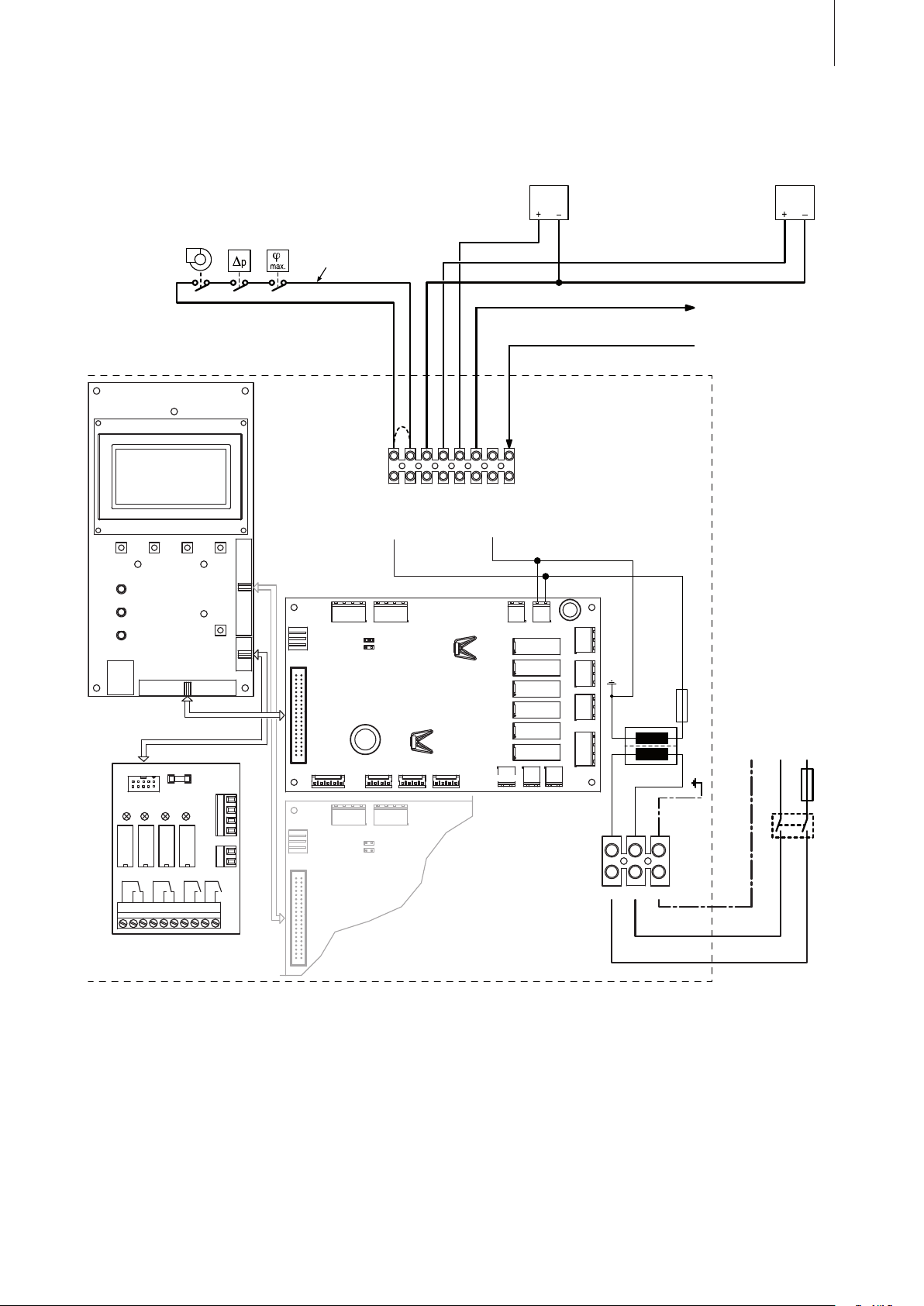
5.9 Electrical Installation
1 2 3 4 5 6 7 8
J1
A2
Z
A1
Y
K1
B1B2B3
F2
0…10 mADC
2…20 mADC
0…20 mADC
4…20 mADC
0…10 VDC
2…10 VDC
0…5 VDC
1…5 VDC
24VAC “Hot”
24VAC “COM”
F1
100mA
Unit ONSteamServiceError
1 2 3 4 5 6 7 8 9 10
H1
L1NPE
220...230V/50...60Hz
L1 N PE
A3
S1
JP3: 5 Vdc, max. 500 mA
JP4: 24 Vdc, max.150 mA
24 Vac
SL
CH1
CH2
+5 Vdc
FTBD
GND
GND
J13-Feedback
JP4
JP3
J10-Modul
J1-RJ45
J2-Driver Board 1
J3 J4-Driver Board 2
J4
PMW1
J19
Float
J6
PMW2J8PMW3
J16
Drain
J15
Fill
Driver
Board 1
Control
Board
J18
24VAC
J17
24VAC
J5-Ign4J3-A/P J7-Ign5 J9-Ign6
J2a-RS485J1-CPU Board
J14
Blower
J13-FeedbackJ10-Modul
Driver
Board 2
J2a-RS485J1-CPU Board
F1
Q
RJ45
Wiring diagram
45
A1 control or sensor signal Y
A2 control or sensor signal Z (air supply limit signal)
A3 Output 24 Vdc (JP4) or 5 Vdc (JP3)
B1 Safety high limit humidistat (building side)
B2 Flow control (building side)
B3 Ventilation interlock (building side)
F1 External Fuse (10 A, slow-acting, building side)
(signal type set via control software)
(signal type set via control software)
220...240 VAC power supply
F2 Fuse (6 A, fast-acting) 24 VAC power supply
H1 Remote operating and fault indication
J1 Cable bridge (if no monitoring devices are connected)
JP3 Jumper (to set output A3 to 5 Vdc max. 500 mA)
JP4 Jumper (to set output A3 to 24 Vdc max. 150 mA)
K1 External safety loop (24 Vac)
Q External service switch or plug-type connector
RJ45 Communication interface (for detailed informations
refer to the separate documentation)
S1 Full tank blow down (24 Vac)
Page 46
46
Installation notes
All work concerning the electric installation must be performed only by adequately qualified personnel
(electrician or workman with equivalent training). Ascertaining the qualifications is the customer‘s
responsibility.
Observe all local regulations concerning the electric installation.
DANGER! Danger of electric shock!
The steam humidifier may be connected to electric mains only after all installation work has been
completed.
CAUTION!
The electronic parts inside the humidifier are very sensitive to electrostatic discharge. To prevent
damage, appropriate measures against electrostatic discharge (ESD protection) must be taken
when carrying out installation work
Primary wiring
Humidifiers require field wiring to primary voltage terminal blocks. Power requirement is 220…240V/50…60Hz,
10 A slow-acting fused (“F1”) circuit, single phase. Wiring is fed through a 22 mm hole in the bottom of the
control compartment. Installation of external service switch “Q” (all pole disconnecting device with a minimum
contact opening of 3 mm) is mandatory.
When installed, the appliance must be electrically grounded in accordance with local codes, if an external
electrical source is utilized.
Connect ground wire to cabinet ground clamp.
External wiring sizes must be in accordance with existing local electrical codes and by-laws.
Remote operation and fault indication (H1)
The Remote operation and fault indication board is equipped with 4 relays for remote operation and fault
indication.
“On”: this relay closes after the humidifier has been powered up
–
– “Steam”: this relay closes as soon as steam is produced
– “Service”: this relay closes when the set maintenance interval has expired
– “Error”: this relay closes when an error occurs
External safety circuit (K1)
To guarantee the safety of the humidification system, monitoring the operation by means of a safety circuit
is an absolute requirement. To accomplish this, the potential-free contacts (250V/2A) of external monitoring
devices (B1: safety high limit humidistat, B2: airflow monitor, B3: ventilation interlock, etc.) are connected in
series to terminals 1 and 2.
Control or sensor signal
The control signal (signal Y) is connected to terminals 3 and 4. The air supply limit signal (signal Z) is con
to terminals 3 and 5. By default the Condair GS is configured for a 0…10 VDC control signals. The
nected
control signal type can be modified via the software (see menu “user settings”, in the operating instructions
for the Condair GS control). The configuration whether the Condair GS is controlled via the internal or via an
external controller is also done via the software.
Output A3
This output is available for custom purposes. The lines are connected to terminals 6 and 7. The output signal
type is configured by setting the jumper on JP3 (5 Vdc max. 500 mA) or on JP4 (24Vdc max. 150 mA).
Full tank blow down 24 VAC (S1)
This input signal can be used for remote triggering a full tank blowdown. If a 24 VAC signal is present for more
than 60 seconds the tank blows down. The signal line is connected to terminals 8 and 7.
-
Page 47

6 Inspecting the installations (Check list)
Before the Condair GS is operated for the first time, the responsible personnel must inspect all
installations for correct execution (observing of local regulations) and check that the unit is
correctly configured. All deficiencies must be corrected by specialist action before commissioning
takes place.
Use the following check list to ascertain that the installations were performed correctly:
– Unit installation
Is the unit in the correct place (see chapter 5.2.1)?
Is the unit correctly aligned vertically and horizontally?
Is steam humidifier properly secured (unit stand fixed to the floor)?
47
– Steam
– Steam distribution pipe
– Steam pipe between steam outlet on unit and steam hose adapter (main steam pipe)
– Steam hose between steam hose adapter and steam distributor
installation
Steam distribution pipe correctly positioned and secured (screws tightened)?
Are the outlet orifices at right angles to the air flow direction?
Maximum length of 6 m?
Minimum bend radius of 4-5 x internal diameter of solid steam pipe?
Is the pipe properly insulated?
Is the correct installation material used?
Is the minimum internal diameter maintained over the entire pipe length?
Maximum length of 4 m?
Minimum bend radius of 300 mm (4-5 x internal diameter with fixed piping)?
Have the instructions for hose positioning been followed?
Steam hose: no sagging (condensate pocket)?
Rigid steam lines: properly insulated? Correct installation material used? Minimum internal
diameter maintained?
Steam hose securely attached with clamps?
Heat expansion during operation and shortening of the hose with ageing taken into con-
sideration?
– Condensate hoses
Downslope of at least 20 %?
Siphons existing and filled with water?
Condensate hoses correctly fixed?
– Water installation
– Filling water supply
Has filter valve (accessory “Z261”) or shut-off valve and filter 5 µm respectively been in-
stalled in supply line?
Have admissible water pressure (3.0 – 8 bar) and temperature (1 – 30 °C) been ob-
served?
Does supply capacity match the humidifier(s)?
Is the piping properly secured and sealed?
Page 48

48
– Water drain
Has minimum inside diameter of drain pipe (at least 45 mm) been maintained throughout
the entire length?
Has drain pipe been installed with a downslope of at least 10 %?
Have temperature-resistant materials been used (up to 100°C)?
Are the hoses and pipes correctly attached and sealed (hose clamps and screwed con-
nections tightened)?
Is the minimum funnel height of 150 mm observed?
– Gas installation
Is the shut-off valve fitted?
Is a sediment separator installed, if steel pipes are used?
Is the gas circuit correctly sealed (leakage check carried out)?
Is the permissible gas pressure being maintained (see the table in 5.5.1)?
Have the correct sealing materials been used?
– Flue gas system
Does the flue gas system comply with the local regulations?
Does flue gas pipe length comply with the maximum recommended (see 5.6.1)?
Is the minimum pipe cross-section (corresponding to the internal diameter at the unit connec-
tion) maintained over the entire length of the pipe?
Have condensate discharge outlets been incorporated where necessary and provided with a
siphon and is the siphon filled with water?
Is the flue gas pipe sealed and has the permitted sealing material been used?
Have all heat-sensitive and easily flammable materials been removed from the vicinity of the
flue gas pipe?
Is the flue gas pipe insulated at all the necessary positions?
Is the flue gas outlet terminal outside the building correctly located?
Have the permitted sealing materials been used?
– Air supply system for room air-independent units (RS units)
Does the air supply system comply with the local regulations?
Does air supply line length comply with the maximum recommended (see 5.7)?
Is the minimum pipe cross-section (corresponding to the internal diameter at the unit connec-
tion) maintained over the entire length of the air supply line?
Is the air supply line correctly sealed and has the permitted sealing material been used?
Is the inlet terminal outside the building correctly located?
– Electrical installation
Does the electrical installation comply with the local regulations?
Do the mains voltages applied correspond to the supply voltage stated on the rating plate of
the unit?
Is the voltage supply correctly fused?
Is the service switch “Q” installed in the supply cable?
Are all components correctly connected in accordance with the wiring diagram?
Are all connection cables fixed?
Are the connecting cables free of tension (fitted through cable glands/secured with cable
clamps?)
Is the Condair GS correctly configured?
Page 49

7 Operation
7.1 Important notes on operation
Qualification of personnel
The Condair GS must only be commissioned and operated by persons who are familiar with equipment
and adequately qualified to undertake this work. Monitoring such qualification is a matter for
the customer.
Initial commissioning must only be undertaken by the Condair service technician or by the customer‘s
own specially trained personnel.
Safety
not store or use gasoline or other flammable vapors and liquids in the vicinity of this or any other
Do
appliance.
49
Should
before shutting off the electrical supply.
Do not operate this appliance if any part has been exposed to excess humidity. Immediately call a
qualified service technician to inspect the appliance and to replace any part of the control system
and any gas control which has been under water.
An open unit must not be operated. Before putting the Condair GS humidifier into operation make
sure all doors are closed and locked with the screw.
For safe operation of the Condair GS humidifier, make sure the ambient conditions meet the respec
tive
To prevent excess humidification the operation of the Condair GS must be monitored by a high limit
on/off humidistat (see chapter 5).
overheating occur, or the gas fail to shut off, shut off the manual gas valve to the appliance
specifications defined in this documentation.
-
Page 50
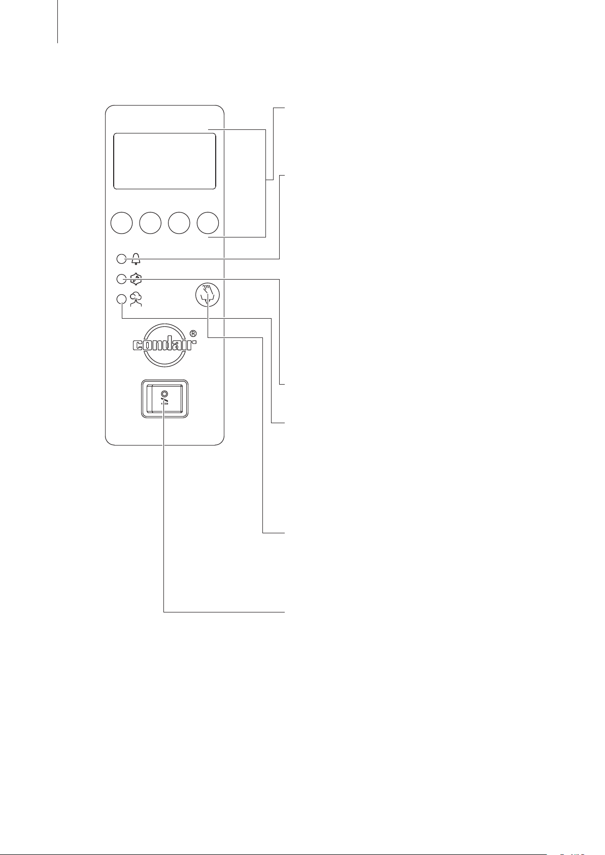
50
7.2 Function of the display and operating elements
Display and control unit
Function: Configuration of the Condair GS.
Indication of operating parameters.
Reset of maintenance counter.
red LED “Fault”
Function: The LED flashes in case of a temporary
malfunction of the unit (Warning status). Further operation of the unit is still possible.The
warning message is shown in the display.
The LED lights in case of a severe malfunction
of the unit (Fault status). Further operation is
not possible any longer. The fault message
is shown in the display.
The LED flashes alternately with the green
LED if the external safety chain (ventilation
interlock has triggered) is open. As soon as
the safety chain is closed again, the indication
disappears.
yellow LED “Maintenance”
Function: The LED lights if the maintenance is due.
green LED “Humidification”
Function: The LED lights if the unit produces steam.
The LED flashes alternately with the red
LED if the external safety chain (ventilation
interlock has triggered) is open. As soon
as the safety chain is closed again, the
indication disappears.
Drain key
Function: Manual draining of the water tank. After
having pressed the drain key, the draining
is controlled via the display and control
unit.
Unit
switch
Function: Switches the unit on and off. The switch is
illuminated when the unit is running.
Page 51

7.3 Commissioning
Before the Condair GS is operated for the first time, the responsible personnel must inspect all
installations for correct execution and check that the unit is correctly configured (see check
list in chapter 6). All deficiencies must be corrected by specialist action before commissioning takes
place.
The humidifier is operated as follows:
1. Examine the humidifier and all installations for possible damage.
CAUTION!
Damaged units and units with damaged installations must not be operated!
2. Check the cleanliness of the outer cabinet:
The panels may be cleaned with a damp cloth and warm soapy water.
CAUTION!
Make sure no water is dripping into the cabinet through the ventilation openings in the unit
housing.
51
. Fill the water tank:
3
• Close the shut-off valve in the gas supply line.
• Open the shut-off valve in the water supply pipe.
• Set humidity controller to maximum humidity demand.
• Switch-on the service switch in the electrical supply circuit.
• Switch-on the humidifier at the unit switch.
• The filling valve opens and the water tank fills (filling time: approx. 30 minutes for the largest
model, for smaller units the filling time is shorter). At the end of the filling cycle the control unit
checks the function of the water level unit. If the control unit has verified the proper function
of the water level unit the ignition sequence starts. After three attempts at ignition the auto
ignition switches off. The red LED lights and a corresponding error message is shown in the
display. Now switch the humidifier Off.
4. Check ignition:
The regulator is still set to maximum humidity demand and the shut-off valve in the gas line is
closed.
Switch-On the humidifier at the unit switch.
•
The combustion air blower starts running for approx. 30 seconds (Pre-purging). Note: On
multi-blower models, wait until all blowers have cycled.
The igniter is activated, then 15 seconds later the gas pressure regulating valve opens. After
4 seconds the gas pressure regulating valve closes and the igniter is de-energized.
After a maximum of three ignition attempts (complete with pre-purging), the humidifier goes
into fault condition.
• Open the shut-off valve in the gas supply pipe.
No gas should flow to the main burner. End of the test.
• Switch-off the humidifier at the unit switch. Note: To reset the safety switch-off, switch-off the
humidifier for at least five seconds and then switch it on again.
• Adjust the humidity controller again to the set humidity value.
Page 52
52
5. Pre-purge of the gas pressure regulating valve(s):
• Disconnect all ignitors from the ignition modules.
• Switch-On the humidifier at the unit switch.
The combustion air blower will pre-purge for 30 seconds. After 15 seconds the gas pressure
regulating valve opens for 4 seconds, then it closes again. After three tries the humidifier goes
into safety lockout.
Note: To reset the safety switch-off, switch-off the humidifier for at least five seconds and then
switch it on again.
Repeat this sequence minimum 2 times in order to make sure no air is left in the gas sy
stem.
Switch-off the humidifier at the unit switch.
•
• Reconnect all ignitors to the ignition modules.
6. Start the humidifier:
• Open the shut-off valve in the water supply pipe.
• Open the shut-off valve in the gas supply pipe.
• Switch on the external service switch.
• Switch the humidifier On at the unit switch.
Condair GS 240
STAR T UP
The Condair GS carries out a system and level test, during which all the
LEDs light up.
If a failure occurs on the system test, a corresponding error message is
shown in the display.
Condair GS 240
Stan dby
03.0 3.200 9 12.0 0.00
Menu
After the system test the unit is in normal operation mode. The display shows
the standard operating display (first page of the indication level).
Note: The contents of the standard operating display depends on the actual
operating status and on the configuration of the Condair GS and can differ
from the opposite display.
-
Condair GS 240
Dema nd :50 %
03.0 3.200 9 12.0 5.00
Menu
As soon as the humidity controller demands humidity, the auto ignition
activates the igniter. This heats up and after approx. four seconds the gas
pressure regulating valve opens. The burner ignites and steam is gene
in the tank via the heat exchanger(s). The green LED lights and the
rated
adjacent display is shown.
If no flame is detected by the flame sensor within three seconds of the ignition,
the gas pressure regulation valve closes again. The ignition sequence
is repeated a maximum of three times, after which the humidifier goes
into system lockout. The red LED lights and an appropriate fault message
appears in the display. At the same time, the operating and remote fault
alarm potential-free contact (“Error”) closes.
Note: The system lockout is reset by switching the humidifier off briefly (5
seconds) and then on again.
Note: for detailed information regarding the operation of the control unit and the configuration settings please observe the information given in the separate operating instructions to the Condair
GS control.
-
Page 53

7.4 Notes on operation
7.4.1 Remote operating and fault indication
Via the operating and fault indication the following operating status are shown remotely:
53
Activated remote
indication relay
“Error” A malfunction (fault status) is
“Service” Maintenance
“Steam demand” Steam demand/
on” Unit switched on Unit switch lights.
“Unit
When? Display on unit
present, further operation is not possible.
mains operational for a certain time.
Steam production
7.4.2 Inspections during operation
During operation the Condair GS and the humidification system have to be inspected weekly. On
this occasion check the following:
is due. The unit re-
LED lights
Red
A corresponding fault message is
shown in the display
Yellow LED lights
The service warning message is
shown in the display
Green LED lights.
The standard operating display is
shown.
The standard operating display is
shown.
• the water, gas and steam installation for any leakage.
• the humidifier and the other system components for correct fixing and any damage.
• the electric installation for any damage.
If the inspection reveals any irregularities (e.g. leakage, error indication) or any damaged compo
take the Condair GS out of operation as described in chapter 7.5. Then, contact your Condair
nents
representative.
7.5 Taking the unit out of operation
If the humidifier must be taken out of operation, e.g. for maintenance work, proceed as follows:
1. Close the shut-off valve in the gas supply pipe.
2. Close the shut-off valve in the water supply pipe.
3. Press the drain switch. The gas pressure regulation valve/s close/s and the tank empties.
Important! If drain pump is defective, drain tank manually via the auxiliary drain.
4. Wait until the water tank empties. Now switch off the humidifier at the unit switch.
-
5. Isolate the humidifier from the electrical power supply: Switch off the external service switch in the
power supply circuit and secure the switch in the Off position to safeguard against unintentional
switch-on.
Page 54

54
8 Maintenance
8.1 Important notes on maintenance
Qualification of personnel
All maintenance work must be carried out only by well qualified and trained personnel authorised
by the owner.
Maintenance and repair of the electrical installation of the Condair GS must be carried out only by
qualified personnel (e.g. electrician) being aware of possible danger and implications.
It is the owner’s responsibility to verify proper qualification of the personnel.
General notes
The instructions and details for maintenance work must be followed and upheld.
Only the maintenance work described in this documentation may be carried out.
Only use original Condair spare parts to replace faulty parts.
Safety
Before
maintenance is initiated, the Condair GS must be taken out of operation in accordance
with instructions in chapter 7.5 and protected against unintentional switching on.
8.2 Maintenance instructions
To maintain operating reliability, the Condair GS must be serviced at regular intervals. Here, a
distinction is made between the first service after 500 hours of operation (I), the minor service
every time the maintenance alarm appears (II) and the annual maintenance (III).
Important! Depending
circumstances it may be necessary to reduce the service interval for the minor maintenance work.
If the lime residues deposited on the floor of the tank exceed a height of 5 cm the interval must
be reduced. If the height is less than 5 cm the interval can be extended.
Important:
Every service action must be documented in the “Maintenance” report sheet (a copy of
this document is provided in these installation, commissioning and service instructions). Warranty
is void if the specified maintenance intervals are not observed and the maintenance work are not
carried out according the instructions.
The following is an overview of the work to be carried out at each of the service stages.
on the hardness of the water and the average steam output, under certain
Components Interval Work required
I II III
ater tank X X X Drain
W
Water outlet pipes, including
siphon
X X X Press
the tank, then open it and measure the height of the
lime residues on the tank floor (max. 5 cm). Remove the
lime from the tank.
Check all pipe connections to the tank (specially the level
unit passages). Clean if necessary.
the drain switch and check for free drainage.
Inspect all pipes for lime deposits and for correct sealing.
Clean or replace pipes with lime deposits. Reseal/replace
leaking pipes.
Page 55
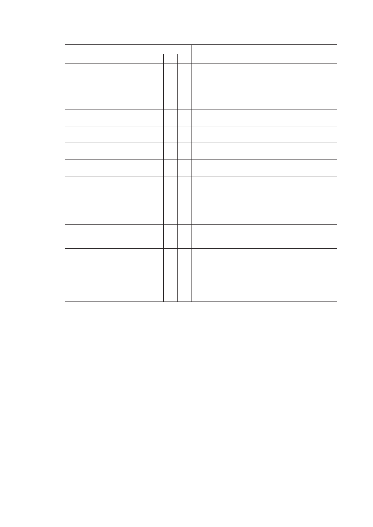
Components Interval Work required
I II III
ater installation X X X Check
W
Unit inner chamber X X X Check
Steam installation X X Inspect
Electrical installation X X Check
Air supply pipe (RS units) X X Check
Flue gas temperature sensor X X V
Flue gas system X X Check
Igniter and flame sensor X Every
Burner / combustion air blower X Remove
all water hoses in the unit for cracks and correct
fixing, replace defective hoses.
Check supply pipes for sealing, seal if necessary. Clean
the filter valve (or water filter).
Check correct function of level unit. Clean or replace if
necessary.
the inner chamber for dirt and deposits and clean
if necessary.
the steam and condensate hoses for cracks and
correct fixing, replace defective hoses.
all cables in the unit for secure fixing and condition
and check the insulation.
for sealing, seal if necessary.
Check screen in air intake terminal, clean if necessary.
isual check that sensor is intact, wired and attached to
the exhaust.
flue gas system for sealing and remove all traces
of condensate. Check screen in flue gas terminal, clean if
necessary. If specified, have the flue gas system inspected
by an appropriate specialist.
year or every 2000 hours (which is reached first).
Remove and replace igniter and flame sensor (special
spares set “Burner parts subject to wear”).
burner and inspect the condition of burner mat.
Blow out burner mat with compressed air or replace burner if
necessary. Replace all burner seals with new ones (special
spares set “Burner parts subject to wear”).
Clean combustion air blower if necessary. The electric motors of the blowers are provided with permanent lubrication
and do not require maintenance.
55
Page 56
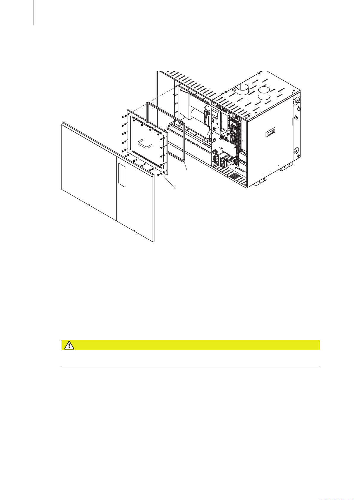
56
8.3 Dismantling work for maintenance and the replacement of components
Prepare water tank for cleaning
Gasket
Torque: 5.7 Nm (50 in-Lb)
1. Take the humidifier out of operation, as described in chapter 7.5.
2. Unlock and remove the left front panel. Then, unscrew the nuts of the side tank cover and remove
the cover.
3. On GS 120 ... 240 only: unlock and remove the left top panel. Then, unscrew the nuts of the top
tank cover and remove the cover.
The re-assembly of the water tank takes place in the reverse sequence. Make sure that the seals of
the tank covers are not damaged (replace if necessary).
Important! Tighten the nuts of the tank cover(s) with a torque wrench (torque: 5.7 Nm). Do not
overtighten the nuts.
Cleaning the water tank
WARNING!
The water and all lime deposits in the tank can be extremely hot and may lead to burning on contact.
Therefore, allow the humidifier to cool before commencing cleaning work.
The combustion chamber walls are usually self-cleaning. Due to the expansion and contraction during
the humidification process, lime deposits peel from the walls and sink to the floor of the tank. An
accumulation of lime on the floor of the tank up to a maximum height of 50 mm is permissible and
does not affect the operation of the humidifier.
• Remove the lime deposits in the tank and combustion chamber walls with a plastic scraper. Do
not use metal spatulas or scrapers, because these are likely to scratch the internal walls of the
tank.
• Remove lime deposits from the floor of the tank with a spatula and/or with an industrial water
suction apparatus. Rinse out residual accumulations of lime with fresh tap water via the open
auxiliary water drain connection (Using a bucket). Never rinse away lime accumulations directly
into the connected water drain outlet, because there is a danger of the drain pump, the drain pipe
and the siphon becoming blocked.
• Remove the hose connections to the tank and clean them internally.
Danger of combustion!
Page 57
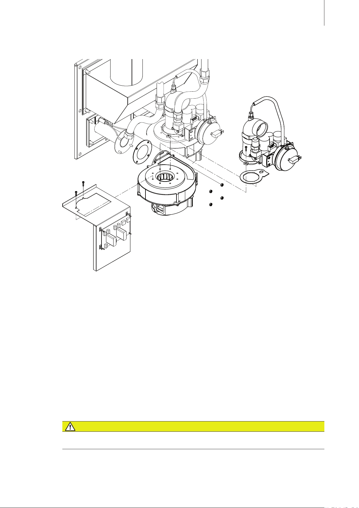
Removal and installation of the combustion air blower
57
1. Take the humidifier out of operation, as described in chapter 7.5.
2. Undo the screw(s) (phillips screwdriver) and remove the right side panel(s).
3. Disconnect cables to combustion air blower, gas pressure regulating valve and pressure switch
(note assignment of the connections).
4. On
RS units only: Undo the hose clamp and remove the air supply hose from the inlet elbow.
Also disconnect the small air hose from the inlet elbow.
5. Undo the coupling of the corresponding flexible gas pipe and disconnect the gas pipe.
6. Undo the two screws of the venturi manifold and lift up the manifold together with the gas pressure re-
gulating valve.
7. Undo the two screws of the electronic board (if present) and remove electronic board.
8. Undo the nuts on the outlet side of the blower and remove the blower unit.
Reinstallation is achieved by following the reverse sequence. Replace defective seals with new ones.
Make sure that all seals are inserted correctly and all cables are connected correctly.
DANGER!
Danger of explosion!
Following maintenance work on the gas system, a leakage test must always be undertaken in
accordance with chapter 5.5.2.
Page 58
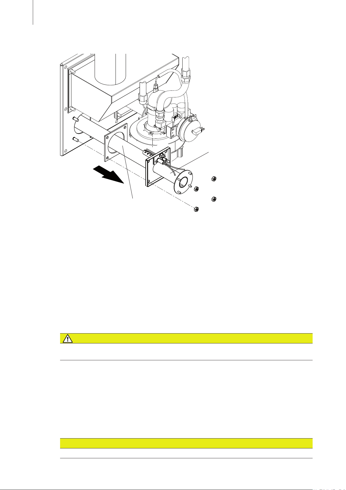
58
Removal and installation of the burner
Hold burner only on metal pipe
Ceramic matting, do not touch!
1. Take the humidifier out of operation, as described in chapter 7.5.
2. Undo the screw(s) (phillips screwdriver) and remove the right side panel(s).
3. Remove the combustion air blower (see the section “Removal and installation of the combustion
air blower” above).
4. Disconnect the cables to the igniter and to the flame monitoring unit and remove the components
(see the section on “Removal and installation of the igniter and the flame sensor”).
5. Unscrew the four nuts in the burner flange and carefully remove the burner unit . Make sure that
the burner is not damaged.
Note:
Grease, dirt and dust at the ceramic matting can affect the performance of the burner.
Re-installation is achieved by following the reverse sequence. Renew the flange seal and replace
igniter and flame sensor if necessary. Tight the nuts of the burner flange with a torque wrench (torque:
10 Nm). Make sure all cables are connected correctly.
DANGER!
Danger of explosion!
Following maintenance work on the gas system, a leakage test must always be undertaken in
accordance with chapter 5.5.2.
Cleaning the burner elements
Carefully blow out the burner element mats (ceramic fibre material) from outside with compressed
air. Severely soiled burner elements should be replaced.
Cleaning the blower/burner chamber of the unit
Carefully clean the blower and the burner chamber by freeing any kind of soiling and accumulations.
CAUTION!
Wet cleaning of the blower and the burner chamber is not permitted!
Page 59
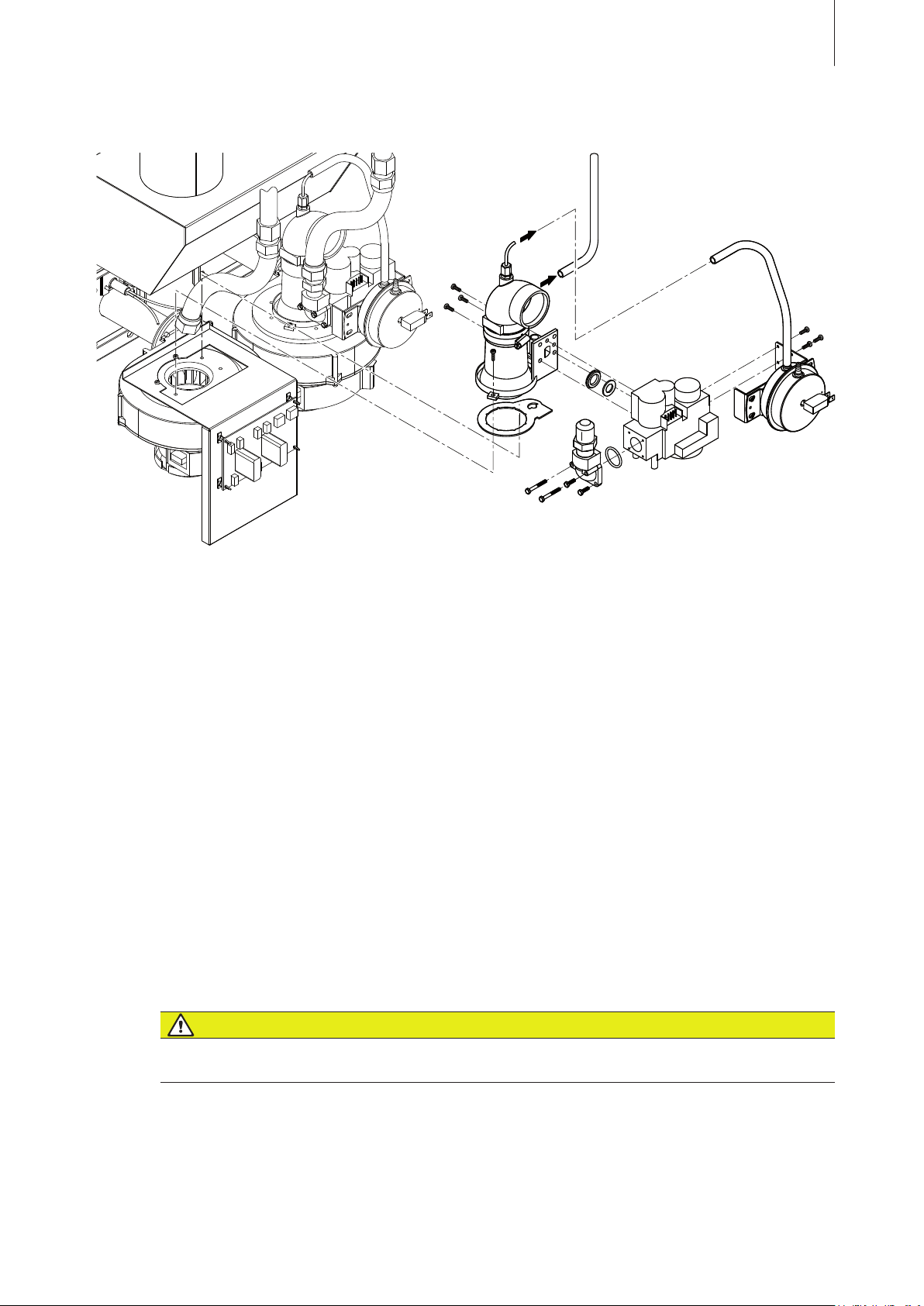
Removal and installation of the gas pressure regulating valve
59
1. Take the humidifier out of operation, as described in chapter 7.5.
2. Undo the screw(s) (phillips screwdriver) and remove the right side panel(s).
3. On RS units only: Undo the hose clamp and remove the air supply hose from the inlet elbow.
Also disconnect the small air hose from the inlet elbow.
4. Disconnect electrical wiring to the gas pressure regulating valve and the pressure switch (note
the connection layout).
5. Undo the coupling of the corresponding flexible gas pipe and disconnect the gas pipe.
6. Undo the two screws of the venturi manifold and lift up the manifold together with the gas pressure re-
gulating valve.
7. Undo the four screws and remove the gas pipe connection of the gas pressure regulating
valve.
8. Pull off the hose connected to the pressure switch (note the connection layout). Then, undo the
three screws of the pressure switch support and remove pressure switch assembly from the gas
regulating valve.
9. Undo the three screws fixing the gas pressure regulating valve to the venturi manifold then,
remove the gas pressure regulating valve from the venturi manifold.
Reinstallation is achieved by following the reverse sequence. Replace defective seals with new ones.
Make sure that all seals are inserted correctly and all cables are connected correctly.
DANGER!
Danger of explosion!
Following maintenance work on the gas system, a leakage test must always be undertaken in
accordance with chapter 5.5.2.
Page 60
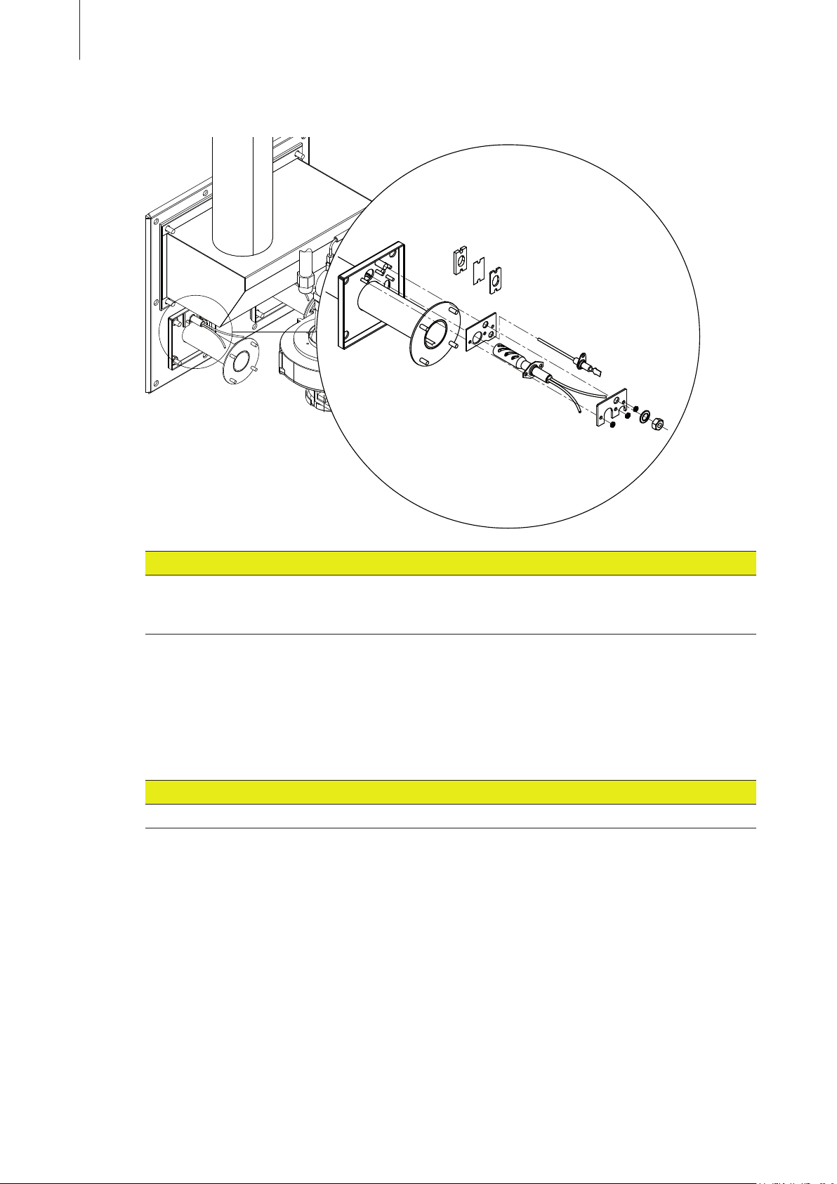
60
Removal and installation of the igniter and the flame sensor
CAUTION!
When replacing the igniter and the flame sensor, use only the set of spares “burner spare parts
subject to wear” available from your Condair supplier, since otherwise the humidifier could be
damaged.
Take the humidifier out of operation, as described in chapter 7.5.
1.
2. Undo the screw(s) (phillips screwdriver) and remove the right side panel(s).
3. Disconnect the wiring connection to the igniter and to the flame sensor.
4. Unscrew the fixing nuts for the igniter and the flame sensor. Now carefully remove the igniter
and flame sensor.
CAUTION!
The silicon carbide igniter is breakable. Therefore handle it with great care to avoid damage.
Reinstallation is achieved by following the reverse sequence. Inspect gaskets and replace if defective.
Make sure that all gaskets are inserted correctly and all cables are connected correctly.
Page 61
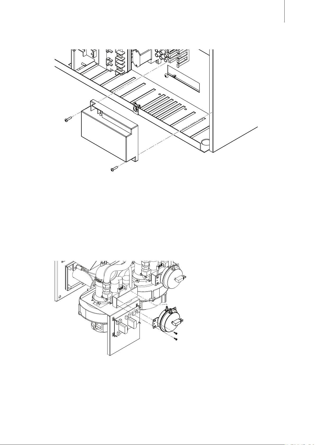
Replacement of the ignition module
61
Take the humidifier out of operation, as described in chapter 7.5.
1.
2. Undo the screw (phillips screwdriver) and remove the right front panel.
3. Note the cable assignment, then remove all connection cables to the ignition module.
4. Unscrew the two fixing screws securing the ignition module and then remove ignition module.
Re-installation follows in the reverse sequence. Make sure the connecting cables are connected
correctly.
Replacement
of the air pressure switch
1. Take the humidifier out of operation, as described in chapter 7.5.
2. Undo the screw(s) (phillips screwdriver) and remove the right side panel(s).
3. Pull off the hose connected to the pressure switch (note the connection layout).
4. Remove the connection cable to the pressure switch (note assignment before removal).
5. Unscrew the two fixing screws and remove the air pressure switch.
Re-installation follows in the reverse sequence. Make sure the cables and the hose are connected
correctly.
Page 62
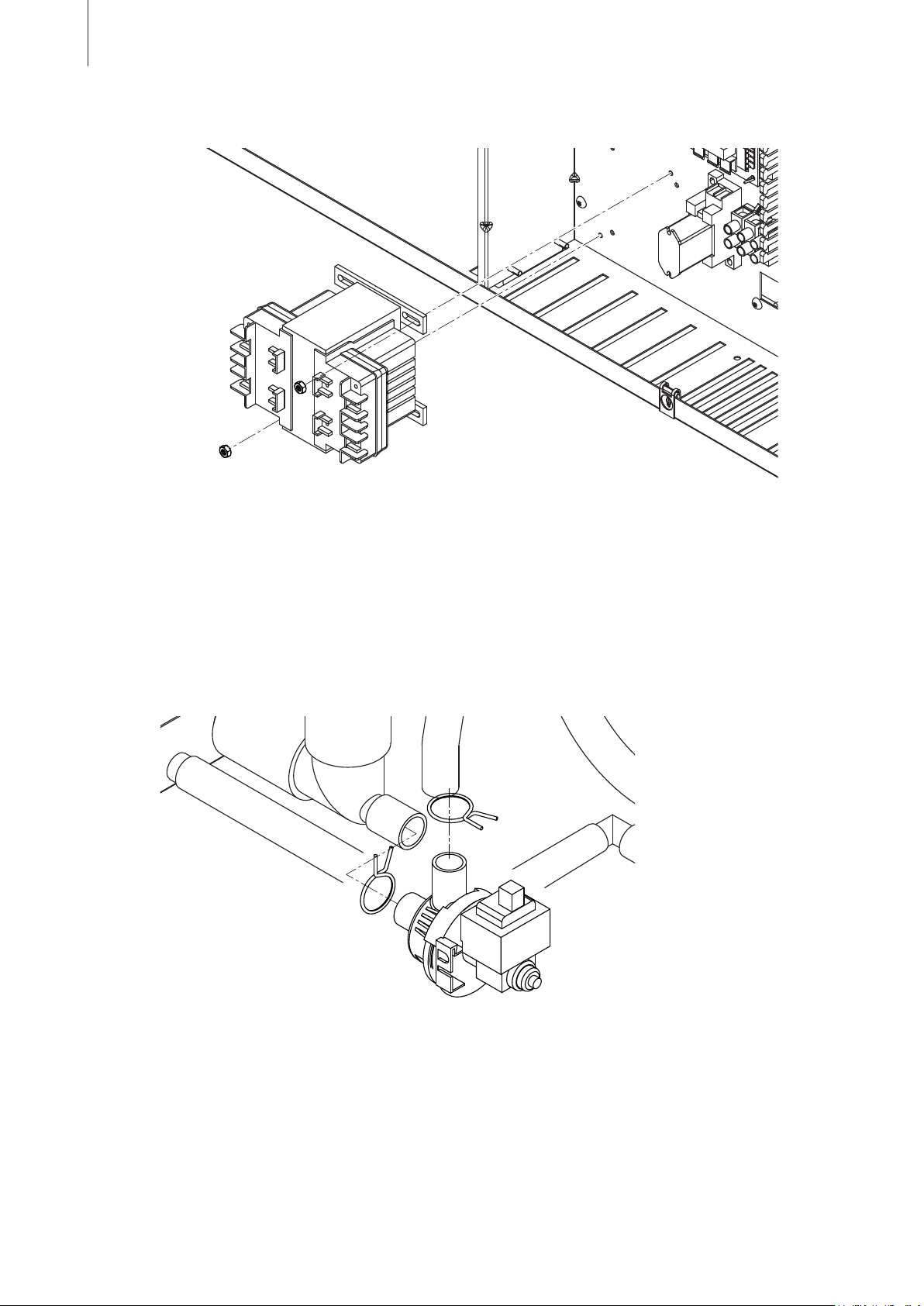
62
Replacing the transformer
1. Take the humidifier out of operation, as described in chapter 7.5.
2. Undo the screw (phillips screwdriver) and remove the right front panel.
3. Remove the connection cables to the transformer, if necessary labeling the cables before removal.
4. Unscrew the two nuts and remove he transformer.
Re-installation is carried out in the reverse sequence. Make sure the cables are connected cor
rectly.
Replacing
the drain pump
-
1. Take the humidifier out of operation, as described in chapter 7.5.
Important! If drain pump is defective, drain tank manually via the auxiliary drain.
2. Undo the screw (phillips screwdriver) and remove the right side panel.
3. Remove the connection cables to the drain pump (note assignment before removal).
4. Remove hose clamps on the drain pump connections and pull off the hoses, then remove the
drain pump.
Re-installation is carried out in the reverse sequence. Make sure the hoses are correctly secured
with the hose clamps and the cables are connected correctly.
Page 63
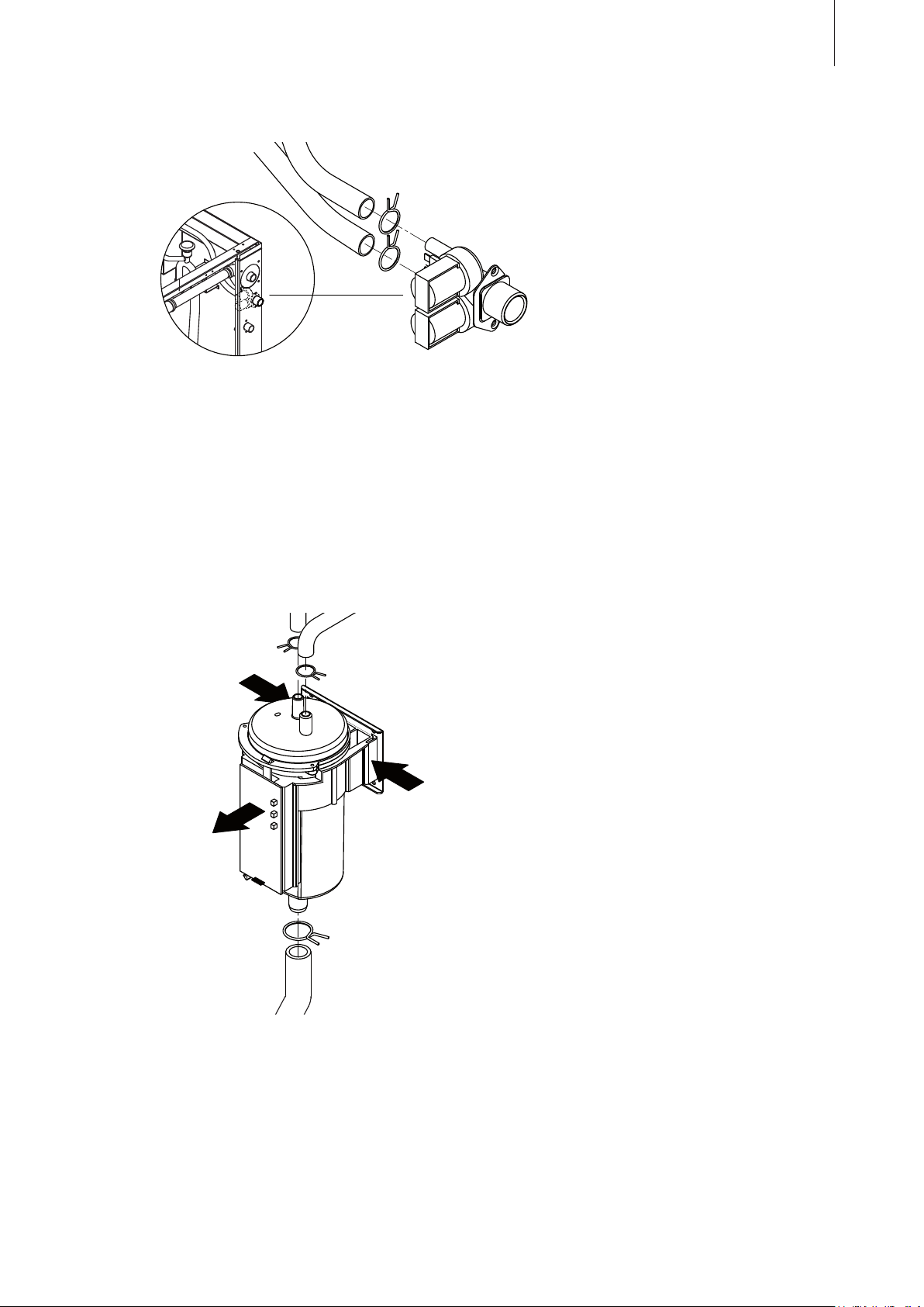
Replacing the fill valve
1. Take the humidifier out of operation, as described in chapter 7.5.
2. Undo the screw (phillips screwdriver) and remove the right side panel.
3. Remove the connection cables to the fill valve (note assignment before removal).
4. Remove hose clamps on the fill valve connections and pull off the hoses.
5. Undo the two screws fixing the fill valve to the housing, then remove the fill valve.
63
Re-installation is carried out in the reverse sequence. Make sure the hoses are correctly secured
with the hose clamps and the cables are connected correctly.
Replacing the water level unit
1. Take the humidifier out of operation, as described in chapter 7.5.
2. Undo the screw (phillips screwdriver) and remove the left front panel.
3. Remove the connection cable to the level unit.
4. Remove hose clamps on the level unit connections and pull off the hoses.
5 Squeeze both sides of the mounting bracket to release it from the slots in the support bracket
behind the water level unit, then remove the level unit.
Re-installation is carried out in the reverse sequence. Make sure the hose are correctly secured with
the hose clamps and the cable is connected correctly.
Page 64
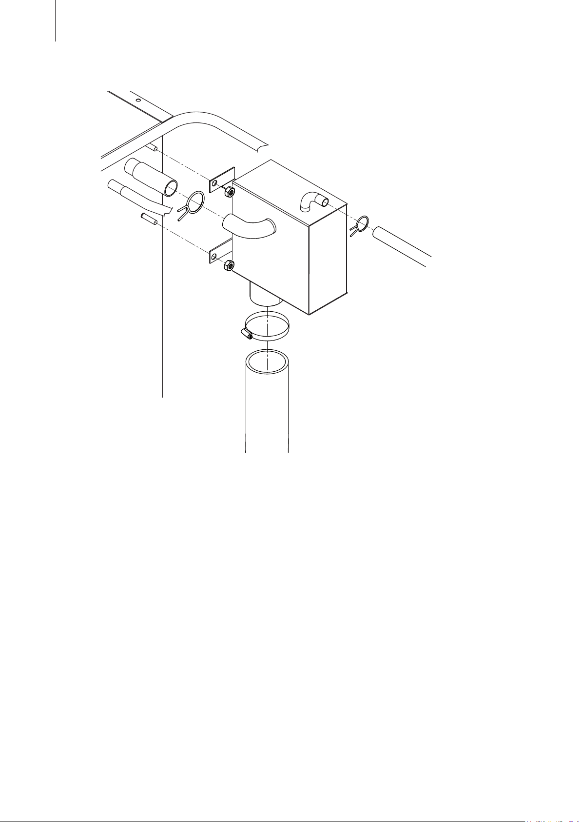
64
Replacing the filling chamber
1. Take the humidifier out of operation, as described in chapter 7.5.
2. Undo the screw (phillips screwdriver) and remove the right side panel.
3. Remove hose clamps on the filling chamber connections and pull off the hoses.
4 Undo the two nuts securing the filling chamber to the face of the tank, then remove the filling
chamber.
Re-installation
is carried out in the reverse sequence. Make sure the hose are correctly secured
with the hose clamps.
Page 65
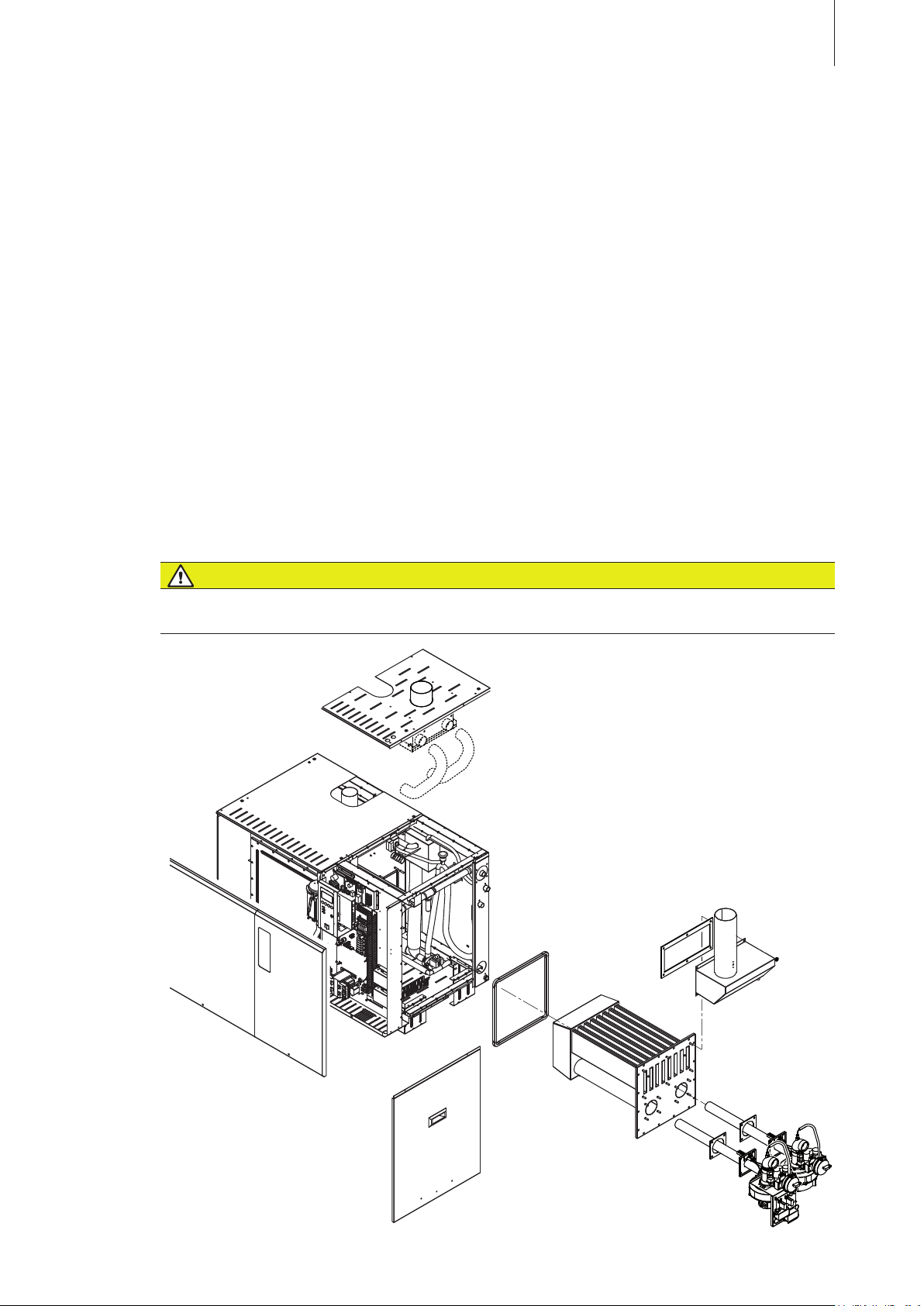
Removal of the heat exchanger (see following illustration)
1. Take the humidifier out of operation, as described in chapter 7.5.
2. Disconnect the gas supply pipe from the connection on the humidifier and close off the pipe.
3. Undo the screw(s) (phillips screwdriver) and remove the right side panel(s).
65
4. On
RS units only: Remove the hoses from air intake manifold and air inlet elbows. Then, dis-
mount air supply pipe at the air supply connection.
5. Dismount flue gas pipe at the flue gas outlet connection.
6. Undo the screw(s) (phillips screwdriver) and remove the left and the right top panels.
7. Free all cable connections to the components (combustion blower, ignition module, air pressure
switch, etc.) of the respective heat exchanger.
Important! Note the connector assignment.
8. Undo the coupling of the respective flexible gas pipe and remove the flexible gas pipe.
9. Dismount the burner with the air blower and the gas pressure regulating valve of the respective
heat exchanger.
10. Unscrew the nuts and remove the flue gas manifold from the heat exchanger.
11. Unscrew the nuts on the heat exchanger and pull out the heat exchanger from the tank.
Re-installation is carried out in the reverse sequence. Replace all seals with new ones. Make sure
all cables are connected correctly.
DANGER!
Danger of explosion!
Following maintenance work on the gas system, a leakage test must always be undertaken in
accordance with chapter 5.5.2.
Page 66

66
8.4 Notes on cleaning agents
The information and specifications relating to the cleaning agents to be used must be strictly observed.
In particular: Information on personal protection, environmental protection and all restrictions in the
use of cleaning agents.
The use of disinfectants is only permitted if they deposit no poisonous residues. In all cases, the
components that have been cleaned in this way are to be rinsed with water.
CAUTION!
Do not use solvents for cleaning purposes, nor aromatized or halogenized hydrocarbons
or other aggressive substances.
local environmental protection regulations without reservation.
Follow
8.5 Resetting the maintenance reminder
After completing maintenance work, the maintenance reminder message must be reset via the reset function in menu mode of the control (see chapter 5.6 in the separate operating instructions for
Condair GS control).
Page 67

9 Troubleshooting
9.1 Important notes on troubleshooting
Qualification of personnel
Have faults eliminated by adequately qualified and trained personnel only. Malfunctions caused by
the electrical installation must be repaired by authorized personnel (e.g. electrician) only.
Safety
eliminating faults, the Condair GS must be taken out of operation, as described in chapter
When
7.5, and prevented from further inadvertent operation.
Make sure the power supply to the unit is cut off (test with voltage tester) and that the stop
valves in the water and gas supply line are closed.
General note
67
Most operational malfunctions are not caused by faulty equipment but rather by improper installa
or disregarding of planning guidelines. Therefore, a complete fault diagnosis always involves a
tion
thorough examination of the entire system. Often, the steam hose connection has not been properly
executed, or the fault lies with the humidity control system.
9.2 Error indication
Malfunctions during operation are indicated by a corresponding warning message (operation still possible, red LED flashes) or a fault message (operation not possible any longer, red LED lights) in the
display of the operating and control unit. Detailed information thereto can be found in the separate
operating instructions for Condair GS control.
9.3 Resetting the error indication
To reset the error indication:
Disconnect the Condair GS from the mains for approx. 5 seconds, then reconnect again.
-
Note: If the fault has not been eliminated, the error indication reappears after a short while.
Page 68

68
10 Specifications
10.1 Technical Data
Condair GS Type 40 80 120 160 200 240
Steam output
room air-dependent
room
air-independent (RS units) kg/h 10…40 10…80 10…120 10…160 10…200 10…240
consumption kw 3
Energy
Gasous fuel Natural gas (G20, G25, G25.1, G27, GZ350) or Propane gas (G31)
Electric connections
power supply 230V/50…60Hz/1Phase
power consumption
power supply fuse 10 A, slow acting
Mechanical Connections
Fill water inlet
Drain Inch 3
Auxiliary drain Inch NPT
Gas line Inch BSP
Steam hose connection Inches 1
Flue pipe connection Inches 3
Humidity control
Possible control signals 0…5VDC / 1…5VDC / 0…10VDC / 0…20mA / 4…20mA
Dimensions
Height cm 81
Width cm 114
Depth cm 5
Shipping weight kg 174 210 295 3
Operating weight
filled kg 211 27
empty kg 140 162 2
Operating conditions
Admissible water pressure
Water quality untreated drinking water or fully demineralized water
Admissible gas supply pressure
Admissible ambient temperature 5…30
Overpressure at the flue outlet
at full load
at minimum load
ype of protection IP20
T
Admissible
Further informations
Conformity CE
Patents Condair®
duct air pressure Pa –800
kg/h 10…40 10…80 10…120 10…160 10…200 10…240
6.5 73.0 109.5 146.0 182.5 219.0
W 460 690 920 1150 1
Inch BSP 3
1/2 BSP 3/4 BSP 1 BSP 1 BSP 1 1/4 BSP 1 1/4
3/4 (45mm) 3 (76 mm) 3 (76 mm) 4 (101 mm) 4 (101 mm) 4 (101 mm)
(76 mm) 4 (101 mm) 5 (127 mm) 5 (127 mm) 6 (152 mm) 6 (152 mm)
(158 unit on stand)
3 69 109 109 149 149
3 459 471 610 623
38 261 290 314
bar 3
mbar G20:
Pa
Pa
17…25 / G25: 20...30 / G25.1: 20...30
G27: 17.5…23 / GZ350: 10.5...16 / G31: 25...57.5
international trademark/international patents
/4
/4 (19 mm)
1/2
19 358 382
…8
80
5
... +1700
380 1610
Page 69

10.2 Flue gas specifications
Natural gas G20 Natural gas G25
full load part load full load part load
Condair GS 40
energy consumption kW 3
gas consumption
kg/h 2.4 0.68 3
3
m
/h 3.478 0.8695 4.0443 1.0111
exhaust temperature °C 180 120 180 120
exhaust
CO
mass flow kg/s 0.015 0.00
-content % 8.9 8 8.7 8
2
flue gas pressure Pa 80 5 80 5
exhaust
Condair
diameter mm 76 76
GS 80
energy consumption kW 7
gas consumption
kg/h 4.72 0.68 6.08 0.87
3
m
/h 6.956 0.8695 8.0886 1.0111
exhaust temperature °C 180 72 180 72
exhaust
CO
mass flow kg/s 0.0
-content % 8.9 4.4 8.7 4.3
2
flue gas pressure Pa 80 5 80 5
exhaust
Condair
diameter mm 101 101
GS 120
energy consumption kW 109.5 10.5 109.5 10.5
consumption
gas
kg/h 7.08 0.68 9.12 0.87
3
m
/h 10.434 0.8695 12.133 1.0111
exhaust temperature °C 180 57 180 57
exhaust
CO
mass flow kg/s 0.045 0.0099 0.051 0.0169
-content % 8.9 2.9 8.7 2.9
2
flue gas pressure Pa 80 5 80 5
exhaust
Condair
diameter mm 127 127
GS 160
energy consumption kW 146 10.5 146 10.5
consumption
gas
kg/h 9.44 0.68 12.16 0.87
3
m
/h 13.9121 0.8695 16.1773 1.0111
exhaust temperature °C 180 49 180 49
exhaust
CO
mass flow kg/s 0.06 0.01
-content % 8.9 2.2 8.7 2.2
2
flue gas pressure Pa 80 5 80 5
exhaust
Condair
diameter mm 127 127
GS 200
energy consumption kW 182.5 10.5 182.5 10.5
consumption
gas
kg/h 11.8 0.68 15.2 0.87
3
m
/h 17.3902 0.8695 20.2216 1.0111
exhaust temperature °C 180 44 180 44
exhaust
CO
mass flow kg/s 0.075 0.0164 0.085 0.0279
-content % 8.9 1.8 8.7 1.7
2
flue gas pressure Pa 80 5 80 5
exhaust
Condair
diameter mm 152 152
GS 240
energy consumption kW 219 10.5 219 10.5
consumption
gas
kg/h 14.16 0.68 18.24 0.87
3
m
/h 20.8682 0.8695 24.2659 1.0111
exhaust temperature °C 180 41 180 41
exhaust
CO
mass flow kg/s 0.09 0.0196 0.102 0.0
-content % 8.9 1.5 8.7 1.5
2
flue gas pressure Pa 80 5 80 5
exhaust
diameter mm 152 152
6.5 10.5 36.5 10.5
.04 0.87
34 0.017 0.0058
3 10.5 73 10.5
3 0.0067 0.034 0.0113
31 0.068 0.0224
69
335
When operating with natural gas G25.1, G27, GZ350 or propane gas (G31), please contact your Condair supplier for the corresponding flue gas specifications
Page 70
Remarks
(e.g. height of the lime residues in the water tank, replaced
parts, measures, etc.)
Signature
Side
3
Condair GS
in d° or ppm
or mg/l CaCO
Water hardness
[h]
hours
Working
III
Annual
Maintenance
II
Small
Maintenance
I
Maintenance
Unit type Serial number Commissioning Software version Location Responsible Internal no.
Maintenance record
Date Time First
Page 71

© Walter Meier (Climate International) Ltd. 2009, Printed in Switzerland
Technical modifications reserved
Page 72

CONSULTING, SALES AND SERVICE:
Solutions for Indoor Climate
Reg.No. 40002-2
Manufacturer:
Walter Meier (Climate International) Ltd.
Talstr. 35-37, P.O. Box, CH-8808 Pfäffikon (Switzerland)
Phone +41 55 416 61 11, Fax +41 55 416 62 62
www.waltermeier.com, [email protected]
 Loading...