

Page 1

Artisan Technology Group is your source for quality
new and certied-used/pre-owned equipment
• FAST SHIPPING AND
DELIVERY
• TENS OF THOUSANDS OF
IN-STOCK ITEMS
• EQUIPMENT DEMOS
• HUNDREDS OF
MANUFACTURERS
SUPPORTED
• LEASING/MONTHLY
RENTALS
• ITAR CERTIFIED
SECURE ASSET SOLUTIONS
SERVICE CENTER REPAIRS
Experienced engineers and technicians on staff
at our full-service, in-house repair center
Instra
Remotely inspect equipment before purchasing with
our interactive website at www.instraview.com
Contact us: (888) 88-SOURCE | sales@artisantg.com | www.artisantg.com
SM
REMOTE INSPECTION
View
WE BUY USED EQUIPMENT
Sell your excess, underutilized, and idle used equipment
We also offer credit for buy-backs and trade-ins
www.artisantg.com/WeBuyEquipment
LOOKING FOR MORE INFORMATION?
Visit us on the web at www.artisantg.com for more
information on price quotations, drivers, technical
specications, manuals, and documentation
Page 2

Real-Time Clock and Interrupt Module (RCIM)
Userís Guide
December 2011
Artisan Technology Group - Quality Instrumentation ... Guaranteed | (888) 88-SOURCE | www.artisantg.com
0898007-600
Page 3

Copyright 2011 by Concurrent Computer Corporation. All rights reserved. This publication or any part thereof is
intended for use with Concurrent Computer Corporation products by Concurrent Computer Corporation personnel,
customers, and end–users. It may not be reproduced in any form without the written permission of the publisher.
The information contained in this document is believed to be correct at the time of publication. It is subject to change
without notice. Concurrent Computer Corporation makes no warranties, expressed or implied, concerning the
information contained in this document.
To report an error or comment on a specific portion of the manual, photocopy the page in question and mark the
correction or comment on the copy. Mail the copy (and any additional comments) to Concurrent Computer Corporation, 2881 Gateway Drive Pompano Beach, FL 3306 9. Mark the envelop e “Attentio n: Real-Time OS Publications
Department.” This publication may not be reproduced for any other reason in any form without written permission
of the publisher.
Concurrent Computer Corporation and its logo are registered trademarks of Concurrent Computer Corporation. All
other Concurrent product names are trademarks of Concurrent while all other product names are trademarks or
registered trademarks of their respective owners. Linux® is used pursuant to a sublicense from the Linux Mark
Institute.
Printed in U. S. A.
Revision History: Level: Effective With:
Original Release -- August 2002 000 RedHawk Linux Release 1.1
Previous Release -- December 2003 210 RedHawk Linux Release 2.0
Current Release -- May 2005 300 RedHawk Linux Release 2.3
Update -- September 2005 310 RedHawk Linux Release 2.3-4.1
Update -- May 2007 320 RedHawk Linux Release 4.2
Update -- April 2008 330 RedHawk Linux Release 5.1
Update -- June 2008 400 RedHawk Linux Release 5.1
Update -- October 2010 500 RedHawk Linux Release 5.4
Update -- December 2011 600 RedHawk Linux Release 6.0
Artisan Technology Group - Quality Instrumentation ... Guaranteed | (888) 88-SOURCE | www.artisantg.com
Page 4

Scope of Manual
Preface
Structure of Manual
This manual is intended for users responsible for the installation and use of the Real-Time
Clock and Interrupt Module (RCIM) on Concurrent Computer Corporation’s iHawk
systems under the RedHawkTM Linux® operating system.
NOTE
Three RCIM models are described in this guide: RCIM I,
RCIM II and RCIM III. The use of the term “RCIM” refers to
functionality common to all three boards. “RCIM I”, “RCIM II”
and “RCIM III” refer to the specific boards. Refer to the section
“Specifications” on page 1-2 for specifications for each of the
boards.
This manual consists of the following:
TM
• Chapter 1, Introduction, contains a general overview and specifications for
the RCIM boards.
• Chapter 2, Hardware, Installation and Configuration, provides a
description of the RCIM boards and connectors, as well as installation and
configuration instructions.
Syntax Nota tion
• Chapter 3, Functional Description, provides the general operation, user
interfaces and configuration options for the clocks and interrupts available
on the RCIM.
• Appendix A, Registers, describes the RCIM registers.
• Appendix B, Calculating RCIM Cable Propagation Delays, provides a
formula for guarding against propagation delay when chaining RCIMs.
• The Index contains an alphabetical reference to key terms and concepts and
the pages where they occur in the text.
The following notation is used throughout this guide:
italic Books, reference cards, and items that the user must specify appear in
italic type. Special terms may also appear in italic.
list bold User input appears in list bold type and must be entered exactly
as shown. Names of directories, files, commands, options and man
page references also appear in list bold type.
iii
Artisan Technology Group - Quality Instrumentation ... Guaranteed | (888) 88-SOURCE | www.artisantg.com
Page 5

RCIM User’s Guide
list Operating system and program output such as prompts, messages and
[] Brackets enclose command options and arguments that are optional.
hypertext links When viewing this document online, clicking on chapter, section,
Related Publications
Title Pub No.
RedHawk Linux Release Notes Version x.x 0898003
listings of files and programs appears in list type.
You do not type the brackets if you choose to specify these options or
arguments.
figure, table and page number references will display the
corresponding text. Clicking on Internet URLs provided in blue type
will launch your web browser and display the web site. Clicking on
publication names and numbers in red type will display the
corresponding manual PDF, if accessible.
RedHawk Linux User’s Guide 0898004
RedHawk Linux Frequency-Based Scheduler (FBS) User’s Guide 0898005
iHawk Optimization Guide 0898011
where x.x = release version
iv
Artisan Technology Group - Quality Instrumentation ... Guaranteed | (888) 88-SOURCE | www.artisantg.com
Page 6

Contents
Preface . . . . . . . . . . . . . . . . . . . . . . . . . . . . . . . . . . . . . . . . . . . . . . . . . . . . . . . . . . . . . . . . . . . . . . . . . . . . . . . . iii
Chapter 1 Introduction
Overview . . . . . . . . . . . . . . . . . . . . . . . . . . . . . . . . . . . . . . . . . . . . . . . . . . . . . . . . . . 1-1
Specifications. . . . . . . . . . . . . . . . . . . . . . . . . . . . . . . . . . . . . . . . . . . . . . . . . . . . . . . 1-2
Chapter 2 Hardware, Installation and Configuration
Board Descriptions . . . . . . . . . . . . . . . . . . . . . . . . . . . . . . . . . . . . . . . . . . . . . . . . . . 2-1
RCIM III. . . . . . . . . . . . . . . . . . . . . . . . . . . . . . . . . . . . . . . . . . . . . . . . . . . . . . . 2-2
Board Illustration. . . . . . . . . . . . . . . . . . . . . . . . . . . . . . . . . . . . . . . . . . . . . 2-2
Connectors and LEDs . . . . . . . . . . . . . . . . . . . . . . . . . . . . . . . . . . . . . . . . . 2-3
LED Functions . . . . . . . . . . . . . . . . . . . . . . . . . . . . . . . . . . . . . . . . . . . . . . 2-3
Input and Output Cables and Connectors . . . . . . . . . . . . . . . . . . . . . . . . . . 2-4
Oscillators . . . . . . . . . . . . . . . . . . . . . . . . . . . . . . . . . . . . . . . . . . . . . . . . . . 2-4
GPS Antenna . . . . . . . . . . . . . . . . . . . . . . . . . . . . . . . . . . . . . . . . . . . . . . . . 2-5
External Interrupt I/O Connector . . . . . . . . . . . . . . . . . . . . . . . . . . . . . . . . 2-5
System Identification. . . . . . . . . . . . . . . . . . . . . . . . . . . . . . . . . . . . . . . . . . 2-7
Daisy Chain Cable. . . . . . . . . . . . . . . . . . . . . . . . . . . . . . . . . . . . . . . . . . . . 2-7
RCIM II . . . . . . . . . . . . . . . . . . . . . . . . . . . . . . . . . . . . . . . . . . . . . . . . . . . . . . . 2-8
Board Illustration. . . . . . . . . . . . . . . . . . . . . . . . . . . . . . . . . . . . . . . . . . . . . 2-8
Connectors and LEDs . . . . . . . . . . . . . . . . . . . . . . . . . . . . . . . . . . . . . . . . . 2-8
LED Functions . . . . . . . . . . . . . . . . . . . . . . . . . . . . . . . . . . . . . . . . . . . . . . 2-9
Input and Output Cable Connectors . . . . . . . . . . . . . . . . . . . . . . . . . . . . . . 2-10
Oscillators . . . . . . . . . . . . . . . . . . . . . . . . . . . . . . . . . . . . . . . . . . . . . . . . . . 2-10
GPS Antenna . . . . . . . . . . . . . . . . . . . . . . . . . . . . . . . . . . . . . . . . . . . . . . . . 2-10
External Interrupt I/O Connector . . . . . . . . . . . . . . . . . . . . . . . . . . . . . . . . 2-10
System Identification. . . . . . . . . . . . . . . . . . . . . . . . . . . . . . . . . . . . . . . . . . 2-12
Daisy Chain Cable. . . . . . . . . . . . . . . . . . . . . . . . . . . . . . . . . . . . . . . . . . . . 2-12
RCIM I . . . . . . . . . . . . . . . . . . . . . . . . . . . . . . . . . . . . . . . . . . . . . . . . . . . . . . . . 2-13
Board Illustration. . . . . . . . . . . . . . . . . . . . . . . . . . . . . . . . . . . . . . . . . . . . . 2-13
Connectors and LEDs . . . . . . . . . . . . . . . . . . . . . . . . . . . . . . . . . . . . . . . . . 2-14
LED Functions . . . . . . . . . . . . . . . . . . . . . . . . . . . . . . . . . . . . . . . . . . . . . . 2-14
Output Cable Connector (P2) . . . . . . . . . . . . . . . . . . . . . . . . . . . . . . . . . . . 2-15
Input Cable Connector (P3). . . . . . . . . . . . . . . . . . . . . . . . . . . . . . . . . . . . . 2-16
External Interrupts Connector (P4) . . . . . . . . . . . . . . . . . . . . . . . . . . . . . . . 2-16
Debug Visibility Connector (P5). . . . . . . . . . . . . . . . . . . . . . . . . . . . . . . . . 2-17
In-System Programming Interface Connector (P6). . . . . . . . . . . . . . . . . . . 2-17
System Identification. . . . . . . . . . . . . . . . . . . . . . . . . . . . . . . . . . . . . . . . . . 2-17
Connection Modes. . . . . . . . . . . . . . . . . . . . . . . . . . . . . . . . . . . . . . . . . . . . . . . . . . . 2-18
Unpacking the RCIM. . . . . . . . . . . . . . . . . . . . . . . . . . . . . . . . . . . . . . . . . . . . . . . . . 2-18
Installation . . . . . . . . . . . . . . . . . . . . . . . . . . . . . . . . . . . . . . . . . . . . . . . . . . . . . . . . . 2-19
Configuration. . . . . . . . . . . . . . . . . . . . . . . . . . . . . . . . . . . . . . . . . . . . . . . . . . . . . . . 2-20
Kernel Configuration . . . . . . . . . . . . . . . . . . . . . . . . . . . . . . . . . . . . . . . . . . . . . 2-20
Driver Configuration . . . . . . . . . . . . . . . . . . . . . . . . . . . . . . . . . . . . . . . . . . . . . 2-20
Static Configuration . . . . . . . . . . . . . . . . . . . . . . . . . . . . . . . . . . . . . . . . . . 2-20
Dynamic Configuration. . . . . . . . . . . . . . . . . . . . . . . . . . . . . . . . . . . . . . . . 2-21
Artisan Technology Group - Quality Instrumentation ... Guaranteed | (888) 88-SOURCE | www.artisantg.com
v
Page 7

RCIM User’s Guide
General Considerations . . . . . . . . . . . . . . . . . . . . . . . . . . . . . . . . . . . . . . . . 2-22
MSI Interrupt Configuration. . . . . . . . . . . . . . . . . . . . . . . . . . . . . . . . . . . . . . . . 2-22
ntp Configuration for GPS Support . . . . . . . . . . . . . . . . . . . . . . . . . . . . . . . . . . 2-23
Verifying ntp/GPS Operation . . . . . . . . . . . . . . . . . . . . . . . . . . . . . . . . . . . . . . . 2-23
Chapter 3 Functional Description
Overview . . . . . . . . . . . . . . . . . . . . . . . . . . . . . . . . . . . . . . . . . . . . . . . . . . . . . . . . . . 3-1
Clocks. . . . . . . . . . . . . . . . . . . . . . . . . . . . . . . . . . . . . . . . . . . . . . . . . . . . . . . . . . . . . 3-1
The Tick Clock . . . . . . . . . . . . . . . . . . . . . . . . . . . . . . . . . . . . . . . . . . . . . . . . . . 3-2
The POSIX Clock . . . . . . . . . . . . . . . . . . . . . . . . . . . . . . . . . . . . . . . . . . . . . . . . 3-2
Direct Access to the Clocks . . . . . . . . . . . . . . . . . . . . . . . . . . . . . . . . . . . . . . . . 3-3
Synchronizing the Clocks . . . . . . . . . . . . . . . . . . . . . . . . . . . . . . . . . . . . . . . . . . 3-3
The rcim_clocksync Utility . . . . . . . . . . . . . . . . . . . . . . . . . . . . . . . . . . . . . 3-3
Synchronizing the Tick Clock . . . . . . . . . . . . . . . . . . . . . . . . . . . . . . . . . . . 3-5
RCIM Masterclock Considerations . . . . . . . . . . . . . . . . . . . . . . . . . . . . . . . 3-5
Synchronizing the POSIX Clock. . . . . . . . . . . . . . . . . . . . . . . . . . . . . . . . . 3-5
Automatic Synchronization . . . . . . . . . . . . . . . . . . . . . . . . . . . . . . . . . . . . . 3-6
Using GPS for System Timekeeping . . . . . . . . . . . . . . . . . . . . . . . . . . . . . . . . . 3-6
Interrupt Processing . . . . . . . . . . . . . . . . . . . . . . . . . . . . . . . . . . . . . . . . . . . . . . . . . . 3-8
Interrupt Processing Logic . . . . . . . . . . . . . . . . . . . . . . . . . . . . . . . . . . . . . . . . . 3-8
Arming and Enabling DIs and ETIs . . . . . . . . . . . . . . . . . . . . . . . . . . . . . . 3-9
Interrupt Recognition Logic . . . . . . . . . . . . . . . . . . . . . . . . . . . . . . . . . . . . 3-9
Setting up Distributed Interrupts . . . . . . . . . . . . . . . . . . . . . . . . . . . . . . . . . 3-10
Obtaining RCIM Values . . . . . . . . . . . . . . . . . . . . . . . . . . . . . . . . . . . . . . . . . . . 3-11
Edge-Triggered Interrupts. . . . . . . . . . . . . . . . . . . . . . . . . . . . . . . . . . . . . . . . . . 3-12
ETI Configuration . . . . . . . . . . . . . . . . . . . . . . . . . . . . . . . . . . . . . . . . . . . . 3-12
ETI Device Files . . . . . . . . . . . . . . . . . . . . . . . . . . . . . . . . . . . . . . . . . . . . . 3-13
User Interface to ETIs . . . . . . . . . . . . . . . . . . . . . . . . . . . . . . . . . . . . . . . . . 3-13
Distributed ETIs. . . . . . . . . . . . . . . . . . . . . . . . . . . . . . . . . . . . . . . . . . . . . . 3-14
Real-Time Clocks (RTCs). . . . . . . . . . . . . . . . . . . . . . . . . . . . . . . . . . . . . . . . . . 3-14
RTC Device Files. . . . . . . . . . . . . . . . . . . . . . . . . . . . . . . . . . . . . . . . . . . . . 3-14
Distributed RTCs . . . . . . . . . . . . . . . . . . . . . . . . . . . . . . . . . . . . . . . . . . . . . 3-14
User Interface to RTCs . . . . . . . . . . . . . . . . . . . . . . . . . . . . . . . . . . . . . . . . 3-15
External Output Interrupts . . . . . . . . . . . . . . . . . . . . . . . . . . . . . . . . . . . . . . . . . 3-15
Configuration. . . . . . . . . . . . . . . . . . . . . . . . . . . . . . . . . . . . . . . . . . . . . . . . 3-16
Programmable Interrupt Generators (PIGs) . . . . . . . . . . . . . . . . . . . . . . . . . . . . 3-16
PIG Device File . . . . . . . . . . . . . . . . . . . . . . . . . . . . . . . . . . . . . . . . . . . . . . 3-16
Distributed PIGs . . . . . . . . . . . . . . . . . . . . . . . . . . . . . . . . . . . . . . . . . . . . . 3-17
Distributed Interrupts . . . . . . . . . . . . . . . . . . . . . . . . . . . . . . . . . . . . . . . . . . . . . 3-17
DI Configuration . . . . . . . . . . . . . . . . . . . . . . . . . . . . . . . . . . . . . . . . . . . . . 3-18
DI Device Files . . . . . . . . . . . . . . . . . . . . . . . . . . . . . . . . . . . . . . . . . . . . . . 3-19
User Interface to DIs . . . . . . . . . . . . . . . . . . . . . . . . . . . . . . . . . . . . . . . . . . 3-19
Appendix A Registers
vi
Artisan Technology Group - Quality Instrumentation ... Guaranteed | (888) 88-SOURCE | www.artisantg.com
RCIM III Registers. . . . . . . . . . . . . . . . . . . . . . . . . . . . . . . . . . . . . . . . . . . . . . . . . . . A-1
RCIM III Address Map. . . . . . . . . . . . . . . . . . . . . . . . . . . . . . . . . . . . . . . . . . . . A-1
RCIM III Registers . . . . . . . . . . . . . . . . . . . . . . . . . . . . . . . . . . . . . . . . . . . . . . . A-3
RCIM II Registers . . . . . . . . . . . . . . . . . . . . . . . . . . . . . . . . . . . . . . . . . . . . . . . . . . . A-21
RCIM II Address Map . . . . . . . . . . . . . . . . . . . . . . . . . . . . . . . . . . . . . . . . . . . . A-21
RCIM II Registers. . . . . . . . . . . . . . . . . . . . . . . . . . . . . . . . . . . . . . . . . . . . . . . . A-23
RCIM I Registers . . . . . . . . . . . . . . . . . . . . . . . . . . . . . . . . . . . . . . . . . . . . . . . . . . . . A-36
Page 8

Contents
RCIM I Address Map . . . . . . . . . . . . . . . . . . . . . . . . . . . . . . . . . . . . . . . . . . . . . A-36
RCIM I Registers . . . . . . . . . . . . . . . . . . . . . . . . . . . . . . . . . . . . . . . . . . . . . . . . A-37
Appendix B Calculating RCIM Cable Propagation Delays
RCIM III . . . . . . . . . . . . . . . . . . . . . . . . . . . . . . . . . . . . . . . . . . . . . . . . . . . . . . . . . . B-1
RCIM II . . . . . . . . . . . . . . . . . . . . . . . . . . . . . . . . . . . . . . . . . . . . . . . . . . . . . . . . . . . B-1
RCIM I. . . . . . . . . . . . . . . . . . . . . . . . . . . . . . . . . . . . . . . . . . . . . . . . . . . . . . . . . . . . B-2
Index . . . . . . . . . . . . . . . . . . . . . . . . . . . . . . . . . . . . . . . . . . . . . . . . . . . . . . . . . . . . . . . . . . . . . . . . . . . . . . . . Index-1
Illustrations
Figure 2-1 RCIM III Board . . . . . . . . . . . . . . . . . . . . . . . . . . . . . . . . . . . . . . . . . . . 2-2
Figure 2-2 RCIM III Connectors and LED Locations . . . . . . . . . . . . . . . . . . . . . . . 2-3
Figure 2-3 RCIM III External Interrupt I/O Connector Pin-outs . . . . . . . . . . . . . . 2-6
Figure 2-4 RCIM II Board . . . . . . . . . . . . . . . . . . . . . . . . . . . . . . . . . . . . . . . . . . . . 2-8
Figure 2-5 RCIM II Connectors and LED Locations . . . . . . . . . . . . . . . . . . . . . . . 2-9
Figure 2-6 RCIM II External Interrupt I/O Connector Pin-outs . . . . . . . . . . . . . . . 2-11
Figure 2-7 RCIM I Board . . . . . . . . . . . . . . . . . . . . . . . . . . . . . . . . . . . . . . . . . . . . . 2-13
Figure 2-8 RCIM I Connectors and LED Locations . . . . . . . . . . . . . . . . . . . . . . . . 2-14
Figure 2-9 RCIM I Output Cable Connector (P2) Pin-outs . . . . . . . . . . . . . . . . . . . 2-15
Figure 2-10 RCIM I Input Cable Connector (P3) Pin-outs . . . . . . . . . . . . . . . . . . . 2-16
Figure 2-11 RCIM I External Interrupts Connector (P4) Pin-outs . . . . . . . . . . . . . 2-17
Figure 3-1 Interrupt Processing Logic . . . . . . . . . . . . . . . . . . . . . . . . . . . . . . . . . . . 3-8
Figure 3-2 Distributed Interrupt Operation Example . . . . . . . . . . . . . . . . . . . . . . . 3-10
Figure A-1 RCIM III Board Status/Control Register (BSCR) . . . . . . . . . . . . . . . . A-3
Figure A-2 RCIM III Firmware Revision/Options Present Register (FWOP) . . . . A-4
Figure A-3 RCIM III Interrupt Enable/Request/Pending/Clear/Arm/Level/Polarity
Registers (IER, IRR, IPR, ICR, IAR, ISLR, ISPR) . . . . . . . . . . . . . . . A-5
Figure A-4 RCIM III External Interrupt Routing Registers (EIRR) . . . . . . . . . . . . A-6
Figure A-5 RCIM III Cable Interrupt Routing Registers (CIRR) . . . . . . . . . . . . . . A-7
Figure A-6 RCIM III PPS Snapshot Register (PPS) . . . . . . . . . . . . . . . . . . . . . . . . A-8
Figure A-7 RCIM III Cable Snapshot Register (CSR) . . . . . . . . . . . . . . . . . . . . . . A-8
Figure A-8 RCIM III Cable Master Time Register (CMTR) . . . . . . . . . . . . . . . . . A-8
Figure A-9 RCIM III Clear Cable Errors Register (CCERR) . . . . . . . . . . . . . . . . . A-9
Figure A-10 RCIM III Output Cable Status Register (OCSR) . . . . . . . . . . . . . . . . A-9
Figure A-11 RCIM III Input Cable Status Register (ICSR) . . . . . . . . . . . . . . . . . . A-10
Figure A-12 RCIM III Tick Clock Upper Register (TCU) . . . . . . . . . . . . . . . . . . . A-10
Figure A-13 RCIM III Tick Clock Lower Register (TCL) . . . . . . . . . . . . . . . . . . . A-11
Figure A-14 RCIM III Tick Clock Status/Control Register (TCSC) . . . . . . . . . . . . A-11
Figure A-15 RCIM III POSIX Clock Seconds Register (PCS) . . . . . . . . . . . . . . . . A-12
Figure A-16 RCIM III POSIX Clock Nanoseconds Register (PCN) . . . . . . . . . . . A-12
Figure A-17 RCIM III POSIX Clock Status/Control Register (PCSC) . . . . . . . . . A-13
Figure A-18 RCIM III POSIX Clock Skip/Add Time Register (PCSAT) . . . . . . . . A-13
Figure A-19 RCIM III Clock Frequency Adjust Register (CFAR) . . . . . . . . . . . . . A-14
Figure A-20 RCIM III RTC Timer Registers (RTCT) . . . . . . . . . . . . . . . . . . . . . . . A-14
Figure A-21 RCIM III RTC Repeat Registers (RTCR) . . . . . . . . . . . . . . . . . . . . . . A-14
Figure A-22 RCIM III RTC Control Registers (RTCC) . . . . . . . . . . . . . . . . . . . . . A-15
Figure A-23 RCIM III Programmable Interrupt Generator Register (PIG) . . . . . . A-16
Figure A-24 RCIM III Programmable Interrupt Set/Clear Registers (PIGS, PIGC) A-16
Figure A-25 RCIM III SPI Count Register (SCR) . . . . . . . . . . . . . . . . . . . . . . . . . A-17
Figure A-26 RCIM III GPS Receive Pointers (GRXP) . . . . . . . . . . . . . . . . . . . . . . A-17
Artisan Technology Group - Quality Instrumentation ... Guaranteed | (888) 88-SOURCE | www.artisantg.com
vii
Page 9

RCIM User’s Guide
Figure A-27 RCIM III GPS Transmit Pointers (GTXP) . . . . . . . . . . . . . . . . . . . . . A-18
Figure A-28 RCIM III GPS Debug Control Register (GDCR) . . . . . . . . . . . . . . . . A-18
Figure A-29 RCIM III GPS Communication Error Register (GCER) . . . . . . . . . . . A-19
Figure A-30 RCIM III SPI Data Buffer (SDB) . . . . . . . . . . . . . . . . . . . . . . . . . . . . A-19
Figure A-31 RCIM III GPS Receive Data Buffer (GRDB) . . . . . . . . . . . . . . . . . . . A-19
Figure A-32 RCIM III GPS Transmit Data Buffer (GRDB) . . . . . . . . . . . . . . . . . . A-20
Figure A-33 RCIM II Board Status/Control Register (BSCR) . . . . . . . . . . . . . . . . A-23
Figure A-34 RCIM II Firmware Revision/Options Present Register (FWOP) . . . . A-24
Figure A-35 RCIM II Interrupt Enable/Request/Pending/Clear/Arm/Level/Polarity
Registers (IER, IRR, IPR, ICR, IAR, ISLR, ISPR) . . . . . . . . . . . . . . A-25
Figure A-36 RCIM II External Interrupt Routing Registers (EIRR) . . . . . . . . . . . . A-26
Figure A-37 RCIM II Cable Interrupt Routing Registers (CIRR) . . . . . . . . . . . . . . A-27
Figure A-38 RCIM II PCI Interrupt Routing Registers (PARR, PBRR, PCRR, PDRR)
. . . . . . . . . . . . . . . . . . . . . . . . . . . . . . . . . . . . . . . . . . . . . . . . . . . . . . . A-28
Figure A-39 RCIM II DDS Adjust Register (DDS) . . . . . . . . . . . . . . . . . . . . . . . . . A-28
Figure A-40 RCIM II PPS Snapshot Register (PPS) . . . . . . . . . . . . . . . . . . . . . . . . A-29
Figure A-41 RCIM II GPS Transmit/Receive Register (GPS) . . . . . . . . . . . . . . . . A-29
Figure A-42 RCIM II Clear Cable Errors Register (CCERR) . . . . . . . . . . . . . . . . . A-29
Figure A-43 RCIM II Tick Clock Upper Register (TCU) . . . . . . . . . . . . . . . . . . . . A-30
Figure A-44 RCIM II Tick Clock Lower Register (TCL) . . . . . . . . . . . . . . . . . . . . A-30
Figure A-45 RCIM II Tick Clock Status/Control Register (TCSC) . . . . . . . . . . . . A-30
Figure A-46 RCIM II POSIX Clock Seconds Register (PCS) . . . . . . . . . . . . . . . . . A-31
Figure A-47 RCIM II POSIX Clock Nanoseconds Register (PCN) . . . . . . . . . . . . A-31
Figure A-48 RCIM II POSIX Clock Status/Control Register (PCSC) . . . . . . . . . . A-32
Figure A-49 RCIM II POSIX Clock Skip/Add Time Register (PCSAT) . . . . . . . . A-32
Figure A-50 RCIM II RTC Timer Registers (RTCT) . . . . . . . . . . . . . . . . . . . . . . . A-33
Figure A-51 RCIM II RTC Repeat Registers (RTCR) . . . . . . . . . . . . . . . . . . . . . . . A-33
Figure A-52 RCIM II RTC Control Registers (RTCC) . . . . . . . . . . . . . . . . . . . . . . A-34
Figure A-53 RCIM II Programmable Interrupt Generator Register (PIG) . . . . . . . A-35
Figure A-54 RCIM II Programmable Interrupt Set/Clear Registers (PIGS, PIGC) A-35
Figure A-55 RCIM I Board Status/Control Register (BSCR) . . . . . . . . . . . . . . . . . A-37
Figure A-56 RCIM I Interrupt Enable/Request/Pending/Clear/ARM/Level/Polarity
Registers (IER, IRR, IPR, ICR, IAR, ISLR, ISPR) . . . . . . . . . . . . . . A-38
Figure A-57 RCIM I External Interrupt Routing Register (EIRR) . . . . . . . . . . . . . A-39
Figure A-58 RCIM I Cable Interrupt Routing Register (CIRR) . . . . . . . . . . . . . . . A-40
Figure A-59 RCIM I Tick Clock Upper Register (TCU) . . . . . . . . . . . . . . . . . . . . . A-41
Figure A-60 RCIM I Tick Clock Lower Register (TCL) . . . . . . . . . . . . . . . . . . . . . A-41
Figure A-61 RCIM I Tick Clock Status/Control Register (TCSC) . . . . . . . . . . . . . A-41
Figure A-62 RCIM I POSIX Clock Seconds Register (PCS) . . . . . . . . . . . . . . . . . A-42
Figure A-63 RCIM I POSIX Clock Nanoseconds Register (PCN) . . . . . . . . . . . . . A-42
Figure A-64 RCIM I POSIX Clock Status/Control Register (PCSC) . . . . . . . . . . . A-42
Figure A-65 RCIM I RTC Control Registers . . . . . . . . . . . . . . . . . . . . . . . . . . . . . . A-43
Figure A-66 RCIM I RTC Timer Registers . . . . . . . . . . . . . . . . . . . . . . . . . . . . . . . A-43
Figure A-67 RCIM I Programmable Interrupt Generator Register (PIG) . . . . . . . . A-44
viii
Artisan Technology Group - Quality Instrumentation ... Guaranteed | (888) 88-SOURCE | www.artisantg.com
Page 10

1
Chapter 1Introduction
This chapter provides an overview and specifications for the Real-Time Clock and
Interrupt Module (RCIM).
NOTE
Three RCIM models are described in this guide: RCIM I,
RCIM II and RCIM III. The use of the term “RCIM” refers to
functionality common to all three boards. “RCIM I”, “RCIM II”
and “RCIM III” refer to the specific boards. The section “Specifications” provides specifications for each of the boards.
Overview 1
The Real-Time Clock and Interrupt Module (RCIM) is a PCI-based card that supports
time-critical applications that require rapid response to external events, synchronized
clocks and/or synchronized interrupts.
1
When RCIM boards of various systems are chained together, an interrupt can be
simultaneously distributed to all connected RCIMs, and from the RCIMs to all the
associated host systems.
A synchronized high-resolution clock is provided so that all the RCIMs in an RCIM chain
on multiple systems can share a common time base. It also provides a local POSIX 1003.1
compliant high resolution clock. An optional GPS module allows alignment of the clock
to GPS standard time. A high stability oscillator is standard. Optional oscillators improve
the accuracy of times measured with the RCIM.
In addition to the clocks, this multi-purpose PCI-based card has the following
functionality:
• connection of external device interrupts
• real time clock timers that can interrupt the system
• programmable interrupt generators which allow generation of an interrupt
from an application program
These functions can all generate local interrupts on the system where the RCIM card is
installed. When systems are chained together, multiple input and output interrupts can be
distributed to other RCIM-connected systems. This allows one timer or one external
interrupt or one application program to interrupt multiple RedHawk Linux systems almost
simultaneously to create synchronized actions.
Artisan Technology Group - Quality Instrumentation ... Guaranteed | (888) 88-SOURCE | www.artisantg.com
1-1
Page 11

RCIM User’s Guide
Specifications 1
Feature RCIM III RCIM II RCIM I
Clocks
POSIX
Length 64 bits (two 32-bit words) 64 bits (two 32-bit words) 64 bits (two 32-bit words)
Resolution High-order 32 bits–1 second
Low-order 32 bits–400 nsec
Oscillator stability +/-2.5 PPM +/-20 PPM +/-100 PPM
Tick Timer
Length 64 bits (two 32-bit words) 64 bits (two 32-bit words) 64 bits (two 32-bit words)
Resolution 64 bit counter of 400 ns ticks 64 bit counter of 400 ns ticks 64 bit counter of 400 ns ticks
Real-Time Clocks
Number 8 8 4
Length 32 bits 32 bits 32 bits
Resolution 1 microsecond
(larger values programmable)
Oscillator stability +/-2.5 PPM +/-20 PPM +/-100 PPM
Local Interrupts
External Edge-Triggered Interrupts 12 12 4
External Output Interrupts 12 12 4
Real-Time Clocks 8 8 4
Distributed Interrupts
Input 12 12 8
Output 12 12 8
Interrupt Response Time
Interrupt to user process < 8 microseconds < 8 microseconds < 8 microseconds
Packaging
Form Factor PCIe PCI PCI
Maximum cable length
(See Appendix B for calculations.)
External Connectors Molex LFH-60 Molex LFH-60 16 position .1’’ Latching Header
PCI Performance x1 66 MHz 64-bit 33 MHz 32-bit
Options
30 meters 32 ft. 10 ft.
GPS Module, Oven Oscillator GPS Module, Oven Oscillator None
Environmental
Operating Temperature 10ο to 40o C 10ο to 40o C 10o to 40o C
Storage Temperature -40o to 65o C -40o to 65o C -40o to 65o C
Relative Humidity 10 to 90% (non-condensing) 10 to 90% (non-condensing) 10 to 80% (non-condensing)
Power
Consumption ~5 watts ~5 watts ~5 watts
High-order 32 bits–1 second
Low-order 32 bits–400 nsec
1 microsecond
(larger values programmable)
High-order 32 bits–1 second
Low-order 32 bits–400 nsec
1 microsecond
(larger values programmable)
1-2
Artisan Technology Group - Quality Instrumentation ... Guaranteed | (888) 88-SOURCE | www.artisantg.com
Page 12

2
Chapter 1Hardware, Installation and Configuration
This chapter provides a description of the RCIM PCI-based boards as well as installation
and configuration information.
Board Descriptions 1
This section provides illustrations and descriptions of the RCIM III, RCIM II and RCIM I
boards.
RCIM II and RCIM I boards mount in a standard PCI slot and the RCIM III board mounts
into a standard PCI-e slot on a host system. A connector is mounted on each RCIM for
connection to external interrupts, and a synchronization cable is included for daisychaining a master RCIM to one or more slave RCIMs.
2
1
Artisan Technology Group - Quality Instrumentation ... Guaranteed | (888) 88-SOURCE | www.artisantg.com
2-1
Page 13

RCIM User’s Guide
GPS Module
Connectors
Oven
Controlled
Crystal
Oscillator
RCIM III 1
Board Illustration 1
Figure 2-1 shows the RCIM III board with optional high stability OCXO (Oven
Controlled Crystal Oscillator) and GPS modules installed.
Figure 2-1 RCIM III Board
2-2
Artisan Technology Group - Quality Instrumentation ... Guaranteed | (888) 88-SOURCE | www.artisantg.com
Page 14

Hardware, Installation and Configuration
Output
Status LED
Input
Status LED
SFP Input
Connector
SFP Output
Connector
GPS Antenna
Connector
External Interrupt
I/O Controller
Connectors and LEDs 1
Figure 2-2 shows the input/output connectors and LEDs on the RCIM III board. Detailed
information on the LEDs and each of the connectors is provided in the following sections.
Figure 2-2 RCIM III Connectors and LED Locations
LED Functions 1
There are two bi-colored status LEDs near the input and output connectors on the
RCIM III board. They will both glow dimly RED when the board is in reset mode
Artisan Technology Group - Quality Instrumentation ... Guaranteed | (888) 88-SOURCE | www.artisantg.com
2-3
Page 15

RCIM User’s Guide
followed by brief intervals of bright RED and GREEN as a test. During normal operation
of the board the LEDs function as follows:
LED description Function
Output
Status
LED
Input
Status
LED
RED solid 10 MHz clock failure
RED 2/sec flash cable option installed but not synchronized or miss-
ing, POSIX clock stopped
GREEN 1/sec flash POSIX clock running without cable option
GREEN 1/sec blink POSIX clock running with cable attached and syn-
chronized
RED/GREEN alternating 2/sec flash
RED 2/sec flash cable option installed but cable unsynchronized or
GREEN solid cable attached and synchronized
POSIX clock running with cable unsychronized or
missing
missing
Input and Output Cables and Connectors 1
The RCIM III uses a pair of standard SFP (small form-factor pluggable) connectors
installed in cages to interface to the RCIM III cable. The cable is used to communicate
interrupts, time stamps and a reference clock between RCIM III boards. The output cable
connector is used when the RCIM is either the master or a slave in the middle of an RCIM
chain (see page 2-18 for a description of RCIM modes). The input cable connector is used
when the RCIM is acting in slave mode or in the middle of an RCIM chain. The cable part
number (HS002-3CBL-xx where xx is length in meters) includes an LC fiber optic cable
and two SFPs that are installed in the empty cages on the master and slave RCIMs. Refer
to the section “Daisy Chain Cable” for more information about the cable.
NOTE
The cable SFPs should only be installed and removed with the
system containing the RCIM III powered down. See the Installation section for ESD caution. Care should be taken to insure that
the SFP modules lock into position and that the RCIM III is not
pushed out of its PCIe slot during the installation of the SFPs. The
fiber optic cables themselves can be installed and removed at any
time without damaging the RCIM III.
Oscillators 1
The temperature compensated crystal oscillator (TCXO) provided with RCIM III has an
accuracy of +/- 2.5 PPM (parts per million).
Two optional oven controlled crystal oscillators (OCXO) provide a temperature stability
of +/- 210 PPB (parts per billion) or +/- 10 PPB (parts per billion).
2-4
Artisan Technology Group - Quality Instrumentation ... Guaranteed | (888) 88-SOURCE | www.artisantg.com
Page 16

Hardware, Installation and Configuration
GPS Antenna 1
The GPS option on the RCIM III includes an active GPS antenna and coaxial cable.
The antenna receives the GPS satellite signals and passes them to the receiver. The GPS
signals are spread spectrum signals in the 1575 MHz range and do not penetrate
conductive or opaque surfaces. Therefore, the antenna must be located outdoors with a
clear view of the sky.
If a different antenna or cable is used, it should match the following specifications:
• 50 Ohm impedence
• 27 dB gain
• 3.3 volt DC power max 30 ma.
External Interrupt I/O Connector 1
The external interrupt I/O connector on the RCIM III is a Molex LFH-60 (Low Force
Helix) that provides twelve outputs and twelve inputs.
The external outputs allow equipment to be attached and controlled by the RCIM. The
outputs are driven by a multiplexer which can select any of the programmable interrupt
generators (PIGs), real-time clock timers (RTCs), edge-triggered interrupts (ETIs) or
distributed interrupts (DIs) to drive the output. The selection is controlled by a set of
configuration registers.
See Chapter 3 for information on using external output interrupts and programmable
interrupts.
The pin-outs for the external interrupt I/O connector are shown in Figure 2-3.
Artisan Technology Group - Quality Instrumentation ... Guaranteed | (888) 88-SOURCE | www.artisantg.com
2-5
Page 17

RCIM User’s Guide
Figure 2-3 RCIM III External Interrupt I/O Connector Pin-outs
2-6
The external interrupt input signals are 5 volt ttl levels. The external interrupt outputs
(labeled
EXT_PIG[0-11]) are driven using a 74ABT16240 line driver. The external interrupt
inputs are terminated with 180 ohms to +5 volts, 330 ohms and 0.1 uf to ground. To drive
this input requires a line driver that can sink at least 30 ma. The input termination limits
the speed of the external interrupt signals and helps prevent noise from causing spurious
interrupts. Since most line drivers can sink more current than they can source, the falling
edge of the signal will be faster.
The signals
EXT_CLKIN and EXT_CLKOUT are used for external 10MHz clocks in or out. An
external clock driving the RCIM III should be capable of driving a 5V ttl signal into a 50
ohm load. The RCIM III will automatically switch to using the external clock if one is
present. The external clock output from the RCIM III is driven using a
74ABT16240 line
driver.
Artisan Technology Group - Quality Instrumentation ... Guaranteed | (888) 88-SOURCE | www.artisantg.com
Page 18

Hardware, Installation and Configuration
The signals
EXT_RXD1, EXT_TXD1, EXT_RXD2, and EXT_TXD2 are RS-232 level signals.
They are currently used for debug purposes.
System Identification 1
The following output to lspci(8) shows the PCI class, vendor and device IDs for the
RCIM III (0e:04.0 (bus:slot.function) will differ on your system):
# lspci -v | grep -i rcim
0e:04.0 System peripheral: Concurrent Computer Corporation RCIM III
Real-Time Clock & Interrupt Module (PCIe) (rev 01)
# lspci -ns 0e:04.0
0e:04.0 Class 0880: 1542:9271 (rev 01)
Daisy Chain Cable 1
The RCIM III uses a fiber optic serial synchronization cable with SFP (small form-factor
pluggable) connectors (part no. HS002-3CBL-xx) to connect RCIM IIIs in an RCIM
chain. The serial data on the cable includes parity and framing information which allow
cable problems to be detected. Polling is done continuously and messages that report the
status of the RCIM III daisy chain cables are output when an error condition is detected.
Messages indicating problems will appear on the systems directly connected by a failing
link.
The serial cables are point to point connections. The “input” cable refers to the cable going
upstream towards the master RCIM. The “output” cable is the downstream connection
away from the master.
RCIM: Input cable disconnected.
RCIM: Input cable connected.
RCIM: Input cable connected but not synchronized.
RCIM: Input cable unsynchronized.
RCIM: Input cable O.K.
RCIM: Output cable disconnected.
RCIM: Output cable connected.
RCIM: Output cable connected but not synchronized.
RCIM: Output cable unsynchronized.
RCIM: Output cable O.K.
RCIM: Cable error on input cable.
RCIM: Cable error on output cable.
The “disconnected” and “connected” messages will only occur based on whether an SFP
is installed in the appropriate cage of the RCIM III.
They will not occur when the optical cable is inserted or removed. They should not occur
during normal operation unless the SFP is not installed correctly or it is malfunctioning.
The “not synchronized” and “unsynchronized” messages indicate that the cable is not
answering attempts to communicate. These messages will occur when the optical cable is
installed or removed. They will also occur when a connected system is powered off.
Artisan Technology Group - Quality Instrumentation ... Guaranteed | (888) 88-SOURCE | www.artisantg.com
2-7
Page 19

RCIM User’s Guide
Oven Controlled
Crystal Oscillator
(OCXO)
GPS Module
Connectors
The last two messages indicate transient errors such as cable parity errors or temporary
loss of cable synchronization. If a transient error occurs, it may require a link in the cable
to resynchronize. If a distributed interrupt is being broadcast on the cable, it may be lost.
Transient errors also affect the synchronization of the tick timers since the cable clock will
not reach all of the systems. Refer to Chapter 3 for instructions for synchronizing clocks.
RCIM II 1
Board Illustration 1
Figure 2-4 shows the RCIM II board with optional high stability OCXO (Oven Controlled
Crystal Oscillator) and GPS modules installed.
Figure 2-4 RCIM II Board
Connectors and LEDs 1
Figure 2-5 shows the input/output connectors and LEDs on the RCIM II board.
2-8
Artisan Technology Group - Quality Instrumentation ... Guaranteed | (888) 88-SOURCE | www.artisantg.com
Page 20

Hardware, Installation and Configuration
RJ45 Cable
Connector
LEDs 1-4
RJ45 Output
Cable Connector
GPS Antenna
Connector
External interrupt
I/O Connector
RJ45 Input
Cable Connector
Detailed information on the LEDs and each of the connectors is provided in the following
sections.
Figure 2-5 RCIM II Connectors and LED Locations
LED Functions 1
The four LEDs for the RJ45 input and output connectors on the RCIM II board function as
follows:
Connector LED Function
RJ45 Output
Cable Connector
RJ45 Input
Cable Connector
LED 1 Red -- Failure, Green -- Activity
LED 2 Cable status:
off cable not connected
yellow cable connected but not synchronized
green cable connected and synchronized
LED 3 Always flashing green
LED 4 Cable status:
off cable not connected
yellow cable connected but not synchronized
green cable connected and synchronized
Artisan Technology Group - Quality Instrumentation ... Guaranteed | (888) 88-SOURCE | www.artisantg.com
2-9
Page 21

RCIM User’s Guide
Input and Output Cable Connectors 1
The output cable connector is used when the RCIM II is either the master, or a slave in the
middle of an RCIM chain (see page 2-18 for a description of RCIM modes). The input
cable connector is used when the RCIM is acting in slave mode.
The cable attached to the output cable connector is an RJ45 serial synchronization cable
(part no. HS002-CBL-10). Refer to the section “Daisy Chain Cable” for more information
about the cable.
Note that although RJ45 cables are used with Gigabit Ethernet, the RCIM II cables are not
Ethernet compatible.
Oscillators 1
The standard crystal oscillator provided with RCIM II has an accuracy of +/- 20 PPM
(parts per million).
Two optional oven controlled crystal oscillators (OCXO) provide a temperature stability
of +/- 210 PPB (parts per billion) or +/- 10 PPB (parts per billion).
GPS Antenna 1
The GPS option on the RCIM II includes an active GPS antenna and coaxial cable.
The antenna receives the GPS satellite signals and passes them to the receiver. The GPS
signals are spread spectrum signals in the 1575 MHz range and do not penetrate
conductive or opaque surfaces. Therefore, the antenna must be located outdoors with a
clear view of the sky.
If a different antenna or cable is used, it should match the following specifications:
• 50 Ohm impedence
• 27 dB gain
• 3.3 volt DC power max 30 ma.
External Interrupt I/O Connector 1
The external interrupt I/O connector on the RCIM II is a Molex LFH-60 (Low Force
Helix) that provides twelve outputs and twelve inputs.
The external outputs allow equipment to be attached and controlled by the RCIM. The
outputs are driven by a multiplexer which can select any of the programmable interrupt
generators (PIGs), real-time clock timers (RTCs), edge-triggered interrupts (ETIs) or
distributed interrupts (DIs) to drive the output. The selection is controlled by a set of
configuration registers.
2-10
See Chapter 3 for information on using external output interrupts and programmable
interrupts.
The pin-outs for the external interrupt I/O connector are shown in Figure 2-6.
Artisan Technology Group - Quality Instrumentation ... Guaranteed | (888) 88-SOURCE | www.artisantg.com
Page 22

Hardware, Installation and Configuration
Figure 2-6 RCIM II External Interrupt I/O Connector Pin-outs
The external interrupt input signals are 5 volt ttl levels. The external interrupt outputs
(labeled
EXT_PIG[0-11]) are driven using a 74ABT16240 line driver. The external interrupt
inputs are terminated with 180 ohms to +5 volts, 330 ohms and 0.1 uf to ground. To drive
this input requires a line driver that can sink at least 30 ma. The input termination limits
the speed of the external interrupt signals and helps prevent noise from causing spurious
interrupts. Since most line drivers can sink more current than they can source, the falling
edge of the signal will be faster.
The signals
EXT_CLKIN and EXT_CLKOUT are used for external 10MHz clocks in or out. An
external clock driving the RCIM II should be capable of driving a 5V ttl signal into a 50
ohm load. The RCIM II will automatically switch to using the external clock if one is
present. The external clock output from the RCIM II is driven using a
74ABT16240 line
driver.
Artisan Technology Group - Quality Instrumentation ... Guaranteed | (888) 88-SOURCE | www.artisantg.com
2-11
Page 23

RCIM User’s Guide
The signals
EXT_RXD1, EXT_TXD1, EXT_RXD2, and EXT_TXD2 are RS-232 level signals.
They are currently used for debug purposes.
System Identification 1
The following output to lspci(8) shows the PCI class, vendor and device IDs for the
RCIM II (0d:06.0 (bus:slot.function) will differ on your system):
# lspci -v | grep -i rcim
0d:06.0 System peripheral: Concurrent Computer Corp RCIM II
Realtime Clock and Interrupts Module (rev 01)
# lspci -ns 0d:06.0
0d:06.0 Class 0880: 1542:9260 (rev 01)
Daisy Chain Cable 1
The RCIM II uses an RJ45 serial synchronization cable (part no. HS002-CBL-10) to
connect RCIM IIs in an RCIM chain. The serial data on the cable includes parity and
framing information which allow cable problems to be detected. Polling is done
continuously and messages that report the status of the RCIM II daisy chain cables are
output when an error condition is detected. Messages indicating problems will appear on
the systems directly connected by a failing link.
The serial cables are point to point connections. The “input” cable refers to the cable going
upstream towards the master RCIM. The “output” cable is the downstream connection
away from the master.
RCIM: Input cable disconnected.
RCIM: Input cable connected.
RCIM: Input cable connected but not synchronized.
RCIM: Input cable unsynchronized.
RCIM: Input cable O.K.
RCIM: Output cable disconnected.
RCIM: Output cable connected.
RCIM: Output cable connected but not synchronized.
RCIM: Output cable unsynchronized.
RCIM: Output cable O.K.
RCIM: Cable error on input cable.
RCIM: Cable error on output cable.
The “not synchronized” and “unsynchronized” messages indicate that the cable is
connected but not answering attempts to communicate. This would be the case if the
connected system was powered off.
The last two messages indicate transient errors such as cable parity errors or temporary
loss of cable synchronization. If a transient error occurs, it may require a link in the cable
to resynchronize. If a distributed interrupt is being broadcast on the cable, it may be lost.
Transient errors also affect the synchronization of the tick timers since the cable clock will
not reach all of the systems. Refer to Chapter 3 for instructions for synchronizing clocks.
2-12
Artisan Technology Group - Quality Instrumentation ... Guaranteed | (888) 88-SOURCE | www.artisantg.com
Page 24

Hardware, Installation and Configuration
Connectors
RCIM I 1
This section provides illustrations and descriptions of the RCIM I board.
Board Illustration 1
Figure 2-7 shows the RCIM I board.
Figure 2-7 RCIM I Board
2-13
Artisan Technology Group - Quality Instrumentation ... Guaranteed | (888) 88-SOURCE | www.artisantg.com
Page 25

RCIM User’s Guide
Output Cable Connector (P2)
Input Cable Connector (P3)
LEDs DS1-DS4
(on Wiring Side
of Board)
External Interrupts Connector (P4)
Connectors and LEDs 1
Figure 2-8 shows the input/output connectors and LEDs on the RCIM I board.
Detailed information on the LEDs and each of the connectors is provided in the following
sections.
Figure 2-8 RCIM I Connectors and LED Locations
LED Functions 1
The four LEDs are on the circuit side of the RCIM I board between the output cable
connector (P2) and the external interrupts connector (P4). They function as follows:
LED Number Function
Red DS1 If on after reset, indicates RCIM module failed
power-up reset.
Yellow DS2 If on, indicates cable clock not connected.
Green DS3 If on, indicates activity in progress.
2-14
Artisan Technology Group - Quality Instrumentation ... Guaranteed | (888) 88-SOURCE | www.artisantg.com
Green DS4 If on, indicates power applied to RCIM.
Page 26

Hardware, Installation and Configuration
Output Cable Connector (P2) 1
The output cable connector is used when the RCIM I is either the master, or a slave in the
middle of an RCIM chain (see page 2-18 for a description of RCIM modes). The cable
attached to the output cable connector is called a synchronization cable (part no. 6010178-
109). The pin-outs for the output cable connector are shown in Figure 2-9.
Figure 2-9 RCIM I Output Cable Connector (P2) Pin-outs
Artisan Technology Group - Quality Instrumentation ... Guaranteed | (888) 88-SOURCE | www.artisantg.com
2-15
Page 27

RCIM User’s Guide
Input Cable Connector (P3) 1
The input cable connector is used when the RCIM I is acting in slave mode (see page 2-18
for a description of RCIM modes). The cable attached to the input cable connector is
called a synchronization cable (part no. 6010178-109). The pin-outs for the input cable
connector are shown in Figure 2-10.
Figure 2-10 RCIM I Input Cable Connector (P3) Pin-outs
External Interrupts Connector (P4) 1
The external interrupts connector on the RCIM I provides four outputs and four inputs.
The external outputs allow equipment to be attached and controlled by the RCIM. The
outputs are driven by a multiplexer which can select any of the programmable interrupt
generators (PIGs), real-time clock timers (RTCs), edge-triggered interrupts (ETIs) or
distributed interrupts (DIs) to drive the output. The selection is controlled by a set of
configuration registers.
See Chapter 3 for information on using external output interrupts and programmable
interrupts.
2-16
Artisan Technology Group - Quality Instrumentation ... Guaranteed | (888) 88-SOURCE | www.artisantg.com
Page 28

Hardware, Installation and Configuration
Pin-outs for the external interrupts connector are shown in Figure 2-11.
Figure 2-11 RCIM I External Interrupts Connector (P4) Pin-outs
Debug Visibility Connector (P5) 1
The debug visibility connector is intended for use on the Concurrent Computer
Corporation manufacturing floor and should not be used outside of that environment.
In-System Programming Interface Connector (P6) 1
The in-system programming interface connector is intended for use on the Concurrent
Computer Corporation manufacturing floor and should not be used outside of that
environment.
System Identification 1
The following output to lspci(8) shows the PCI class, vendor and device IDs for the
RCIM I (0d:06.0 (bus:slot.function) will differ on your system):
# lspci -v | grep -i rcim
0d:06.0 System peripheral: PLX Technology, Inc. RCIM Realtime
Clock and Interrupts Module old ID (rev 01)
# lspci -ns 0d:06.0
0d:06.0 Class 0880: 10b5:8845 (rev 01)
Artisan Technology Group - Quality Instrumentation ... Guaranteed | (888) 88-SOURCE | www.artisantg.com
2-17
Page 29

RCIM User’s Guide
Connection Modes 1
When RCIM boards of various systems are chained together, an interrupt can be
simultaneously distributed to all connected RCIMs, and from the RCIMs to all the
associated host systems.
NOTE
All RCIMs in a chain must be the same model; for example, all
RCIM IIs.
If your system will be part of an RCIM chain, it is best to determine the desired connection
mode before installing an RCIM; it is easier to connect the cable to the cable connectors
before the RCIM is installed.
Note that to reconfigure an RCIM chain, the systems must be powered off and rebooted
after moving the cables. The driver determines if a system is the master RCIM at boot time
and configures the master system to control the cable clock and its enable. Swapping the
cables without rebooting the systems will result in problems with the cable clock.
An RCIM can be connected in one of the following modes:
Isolated mode There are no connections to any other RCIM.
Master mode The RCIM is at the head of a chain of RCIMs. There is no cable
connection going into this RCIM, only a cable connection going out.
The RCIM master is unique in that it controls the clocks (see
Chapter 3 for a discussion).
Pass-through The RCIM is connected to two other RCIMs. There is an input
Slave mode cable connection coming from the previous RCIM in the chain, and
an output cable connection going to the next RCIM in the chain.
Final Slave mode The RCIM is connected to one other RCIM. There is an input cable
connection going into a final slave RCIM but no output cable
connection coming out of it.
Unpacking the RCIM 1
When unpacking the equipment from the shipping container, refer to the packing list and
verify that all items are present. Save the packing material for storing and reshipping the
equipment.
2-18
NOTE
If the shipping container is damaged upon receipt, request that the
carrier’s agent be present during unpacking and inspection of the
equipment.
Artisan Technology Group - Quality Instrumentation ... Guaranteed | (888) 88-SOURCE | www.artisantg.com
Page 30

Hardware, Installation and Configuration
Installation 1
Normally, installation and configuration of the card is done by Concurrent Computer
Corporation. This information is provided for those cases where an RCIM is added to a
system in a post-manufacturing environment.
In order to successfully install the RCIM, you must know if you will be using the RCIM to
accept or deliver external interrupts and the mode in which the RCIM will run (isolated,
master, pass-through slave or final slave). Refer to the section “Connection Modes” above
for details.
CAUTION
Avoid touching areas of integrated circuitry as static discharge can
damage circuits.
Concurrent Computer Corporation strongly recommends that you
use an antistatic wrist strap and a conductive foam pad when
installing or upgrading a system. Electronic components such as
disk drives, computer boards, and memory modules can be
extremely sensitive to Electrostatic Discharge (ESD). After
removing the board from the system or its protective wrapper,
place it flat on a grounded, static-free surface, component side up.
Do not slide the board over any surface.
If an ESD station is not available, you can avoid damage resulting
from ESD by wearing an antistatic strap (available at electronic
stores) that is attached to an unpainted metal part of the system
chassis.
Use the following procedure to install an RCIM in your system:
1. Ensure that your system is powered down.
2. Remove the power cable from the system.
3. Open the case of your system and identify the PCIe slot (RCIM III) or PCI
slot (RCIM II or RCIM I) where you want the RCIM to reside. In general,
it is best for the RCIM to be configured in a slot where minimal or no
contention with other devices occurs and at the highest IRQ priority
possible. Refer to the iHawk Optimization Guide, publication number
0898011, for slot configuration guidelines.
4. Install the RCIM into the desired slot, securing the card in the slot using the
mechanism provided by the case.
5. If this is to be part of an RCIM chain, attach the cable as required. See the
section “Connection Modes” to determine how to connect the cable based
on the connection mode for this system.
6. If you are installing an RCIM board equipped with the optional GPS module, attach the GPS antenna lead and mount the antenna. The antenna
should be mounted on the rooftop or in an open area. Refer to the sections
“Connectors and LEDs” and “GPS Antenna” more information about the
antenna.
7. Replace the cover.
8. Attach the power cable to the system.
9. Apply power and boot the system.
Artisan Technology Group - Quality Instrumentation ... Guaranteed | (888) 88-SOURCE | www.artisantg.com
2-19
Page 31

RCIM User’s Guide
Configuration 1
Kernel Configuration 1
The following RedHawk Linux kernel parameters are associated with the RCIM. All are
accessible through the Character Devices selection of the Kernel Configuration GUI
and are enabled by default in all the pre-built RedHawk Linux kernels.
RCIM This parameter configures the RCIM driver in the kernel. It can be
configured as a module, if desired.
MULTI_RCIM Selects whether the multi-board or the single-board RCIM driver is
to be compiled into the kernel. The multi-board driver is used by
default.
RCIM_MASTERCLOCK This parameter enables the RCIM to be used as a master clock thta
monitors and adjusts system time, resulting in more precise system
timekeeping.
RCIM_PPS This parameter disciplines the RCIM tick and POSIX time-of-day
registers to the pulse-per-second support of the optional GPS
receiver. This provides for time more closely aligned to the official
atomic time as defined by the GPS system. This option has no
effect if your RCIM does not have GPS capability.
RCIM_IRQ_EXTENSIONS This parameter allows other drivers to attach their own interrupt
routines to the RCIM driver. The Frequency-based Scheduler
(FBS) requires this support.
For complete information about modifying kernel tunables and building a kernel, refer to
the RedHawk Linux User’s Guide, publication number 0898004.
Driver Configuration 1
This section describes two methods for configuring an RCIM board: dynamic, via the
writing of a string to a /proc file, and static, via boot time (or module load time) options.
The single-board RCIM driver supports static and dynamic, however the multi-board
driver supports only the dynamic method.
Static Configuration 1
When the single-board RCIM driver initializes on a system, it looks at the value of a single
tunable (rcim=RCIMoptions) for its configuration options. For a statically linked RCIM
driver, this tunable can be specified on the GRUB boot loader command line. For an
RCIM in module form, this tunable can be specified on the insmod(8) command line,
or be placed in modprobe.conf(5) where the modprobe(8) invocation in the
startup script /etc/init.d/rcim will find it.
2-20
The following functionality is defined with the rcim tunable:
Artisan Technology Group - Quality Instrumentation ... Guaranteed | (888) 88-SOURCE | www.artisantg.com
Page 32

Hardware, Installation and Configuration
• the manner in which various interrupts will be triggered: rising or falling
edge, high or low level
• associations between interrupts, output lines and distributed interrupt lines
• the name of the system in an RCIM chain that has the master RCIM
• whether tick clocks are to run locally or be synchronized with the clock of
the master RCIM system in a chain
• whether the RCIM is registered as a master clock
The rcim tunable accepts a comma-separated list of options. For example:
rcim=’host/server1.ccur.com, eti1/rising, di3/high, rtc3|di6’
In this example for an RCIM slave system, the RCIM master system name is
server1.ccur.com, edge-triggered interrupt (eti) #1 is configured to trigger on the rising
edge, distributed interrupt (di) #3 triggers on a high value, and distributed interrupt line
(di) #6 is to be driven by real-time clock timer (rtc) #3.
The sync/nosync options affect clock synchronization across an RCIM chain. “sync”
specifies that the RCIM is to use the cable clock driven by the master RCIM’s local clock.
This is the default.“nosync” specifies that the RCIM uses its local clock.
The clock/noclock options define whether the RCIM is registered as a clocksource for the
system. The default is “clock.” Note that once the RCIM is registered as a clocksource, it
cannot be “unregistered.” Also if the RCIM is configured as a module and registered as a
clocksource, the module will be locked in (‘rmmod rcim” will fail).
On RCIM III and RCIM II systems, the timing sources for RTCs, tick and POSIX clocks
can be configured individually, if desired. For example,
rcim=nosync/r,sync/tp
selects the local clock for the RTCs (r) and the cable clock for the tick (t) and POSIX (p)
clocks. If specifiers are not provided for sync and nosync, all three clocks are set
according to the option in effect.
Dynamic Configuration 1
Configurations can be modified dynamically using echo(1) to write a configuration
string, in the format used by the rcim tunable, to /proc/driver/rcimN/config
(where N is the RCIM card number starting from zero). For example:
echo eti1/f > /proc/driver/rcim0/config
changes eti #1 to trigger on a falling edge. Quotes must be used to surround a
configuration request that contains a vertical bar; for example:
echo “rtc0|di1” > /proc/driver/rcim2/config
Configuration modifications made in this way are not retained when the system is
rebooted. Making these changes requires write permission to the file and should only be
made when the RCIM is not in use.
Refer to Chapter 3 or the rcim(4) man page for complete information about
configuration defaults and selections for each interrupt type.
Artisan Technology Group - Quality Instrumentation ... Guaranteed | (888) 88-SOURCE | www.artisantg.com
2-21
Page 33

RCIM User’s Guide
General Considerations 1
When configuring the RCIM systems, keep the following in mind:
• For a chain of RCIMs, the tick clock and POSIX clock in all slave RCIMs
will be synchronized with the master because the clock signal incrementing
time in the master is broadcast to all slaves. Once the clocks on all RCIMs
are initially syncronized they will remain synchronized.
To synchronize tick clocks, a working TCP/IP connection between all
systems is needed. In addition, each slave RCIM hostname configuration
must be set to the master RCIM, and each slave must be configured to run
the rcim_clocksync init script once on boot. This is only required if
your application is using the tick clock for synchronization.
ntp can be used to synchronize the POSIX clocks, however for the RCIMIII there is a better mechanism: rcimdate(8). The RCIM-III master
broadcasts its POSIX time down the RCIM cabling once per second;
rcimdate uses this to make the slave POSIX clocks exactly match the
master. This has several advantages over ntp: no TCP/IP connections
between systems are required, synchronization is faster, and
synchronization is extremely accurate.
• Interrupts, whether operating locally or distributed across an RCIM chain,
will be processed according to the values configured on each system. If you
wish them to function in a manner different from established defaults, the
desired configuration options must be specified.
• When distributing interrupts across the systems in an RCIM chain, all
systems must have a compatible configuration for the distributed interrupt
lines.
MSI Interrupt Configuration 1
The latest version of RCIM III (revision 9 and later) supports MSI (message signaled
interrupts). By default, the RCIM kernel driver will initialize the hardware to use MSI
interrupts instead of PCI INTA interrupts whenever possible. By using MSI interrupts, the
RCIM III is guaranteed of having its own non-shared interrupt, thus providing more
reliable interrupt response times.
The RCIM driver has an rcim.nomsi=1 option which is independent of the rcim=
configuration option described earlier. All versions of the driver have this option. If
specified the MSI capability is disabled on all RCIM boards that support it. There is no
mechanism to pick which boards are to be MSI-disabled and which ones are not. When
this option is specified, the RCIM driver will fallback to using the PCI INTA interrupt
method. For perfomance reasons, this option should only be used if a problem with MSI
interrupts is encountered.
2-22
For a statically linked RCIM driver, this tunable can be specified on the GRUB boot
loader command line (rcim.nomsi=1). For an RCIM in module form, this tunable can
be placed in /etc/modprobe.conf as “options rcim.nomsi=1”.
This option has no effect on RCIM II or RCIM I systems.
Artisan Technology Group - Quality Instrumentation ... Guaranteed | (888) 88-SOURCE | www.artisantg.com
Page 34

Hardware, Installation and Configuration
ntp Configuration for GPS Support 1
If your system contains the optional GPS module, ntp must be installed and configured to
use the GPS receiver to synchronize the RCIM’s POSIX clock to GPS time. Follow these
steps:
1. Verify that the latest ntpd rpm is installed on the system:
# rpm -ql ccur-ntp-4.2.2p1-7*
*
includes possible updates (.1, .2, etc.) and the architecture type, i386 or
x86_64.
If it is not installed, refer to the RedHawk Linux Release Notes, publication number
0898003, for instructions to install this rpm from the RedHawk installation media.
2. The file /etc/ntp.conf supplied with the rpm contains the following
lines that are required to use the GPS.
server 127.127.8.0 mode 138 prefer #PARSE TSIP (10)+ PPS(128)
fudge 127.127.8.0 flag3 1 #enable PPS signal
The following three lines define a pool of world-wide servers that are randomly
selected at poweron for time synchronization. This feature acts as the default NTP
configuration and serves as backup to GPS. You may wish to include your local
country code before “pool” in these entries for best results; e.g.,
0.us.pool.ntp.org. See www.pool.ntp.org for more information.
server 0.pool.ntp.org
server 1.pool.ntp.org
server 2.pool.ntp.org
A block of commented out entries beginning with “logfile” is used to configure files
used for logging statistics. Uncomment the entries if you wish to enable them.
In addition to the log files, ntpq(1) and ntpdc(1) are used for NTP monitoring.
For more information about NTP, refer to the ntpd(1) man page and
www.ntp.org.
At system poweron, once all data is received from the GPS satellites, accurate
timekeeping is available.
Verifying ntp/GPS Operation 1
To determine when the GPS is producing accurate time, use the peer listing of ntpq(1)
as shown below. This example utilizes command line options, however ntpq can also be
run interactively. Refer to the man page for complete information.
# /usr/sbin/ntpq -np
remote refid st t when poll reach delay offset jitter
========================================================================================
xns2.medbanner.c 192.43.244.18 2 u 33 64 377 72.443 -2.897 11.235
+toshi.keneli.or .GPS. 1 u 43 64 377 27.915 0.938 2.075
Artisan Technology Group - Quality Instrumentation ... Guaranteed | (888) 88-SOURCE | www.artisantg.com
2-23
Page 35

RCIM User’s Guide
-216.56.81.86 193.131.101.50 3 u 33 64 377 49.388 -0.579 2.710
+new.localdomain .GPS. 1 u 42 64 377 0.182 0.010 0.020
*GENERIC(0) .GPS. 0 l 46 64 377 0.000 0.000 0.001
The output shows how the system time compares to other time sources. This includes the
GPS receiver and other time servers.
The column labeled remote is the hostname of the timeserver. The system
new.localdomain is a local network time server; GENERIC(0) is the GPS attached to
the RCIM. The other lines are time servers assigned by pool.ntp.org. The first column
indicates which servers are being selected for synchronization. The '*' in front of
GENERIC(0) indicates that the RCIM GPS receiver is being used as the system peer.
The columns delay, offset, and jitter are all times in milliseconds. The offset is
the difference between the local system time and the time source. In this case we are
synchronized to the GPS receiver to microsecond accuracy.
The delay field is the measured network delay to exchange the time with the remote
server.
The jitter measures the difference between offset values from the same source.
The refid indicates where the remote system gets its time.
The st column is the stratum number. A stratum zero system should have a direct
connection to an authoritative source.
The poll column shows how frequently this server is being polled. The when column is
the time in seconds since the last poll.
The reach column is a bitmap in octal which shows if recent polls have been successful.
The value 377 would indicate that the last 8 polls suceeded.
Another indicator is through the ntpq clockvar command:
# /usr/sbin/ntpq
ntpq> clockvar
assID=0 status=0003 clk_okay, last_clk_fault,
device="Trimble GPS (TSIP) receiver", timecode="\x10\xff\x02\x10",
poll=52, noreply=0, badformat=0, baddata=0, fudgetime1=20.000,
stratum=0, refid=GPS, flags=4,
refclock_ppstime="c66be732.00000000 Tue, Jun 28 2005 15:11:46.000",
refclock_time="c66be734.03ffffff Tue, Jun 28 2005 15:11:48.015",
refclock_status="TIME CODE; PPS; POSITION; (LEAP INDICATION; PPS SIGNAL; POSITION)",
refclock_format="Trimble TSIP",
refclock_states="*NOMINAL: 00:54:26 (98.04%); NO RESPONSE: 00:00:02 (0.06%); FAULT:
00:01:03 (1.89%); running time: 00:55:31",
trimble_tracking_status[08]="ch=4, acq=ACQ, eph=19, signal_level= 6.40, elevation= 9.12,
azimuth= 34.35, collecting data",
trimble_satview="mode: 2D-AUTO, PDOP 8.96, HDOP 8.91, VDOP 1.00, TDOP 2.90, 3 satellites
in view: 18, 26, 29",
trimble_tracking_status[10]="ch=0, acq=ACQ, eph=3, signal_level= 2.60, elevation= 18.18,
azimuth= 86.56, collecting data",
trimble_tracking_status[18]="ch=1, acq=ACQ, eph=19, signal_level= 5.20, elevation= 39.47,
azimuth= 289.19, collecting data",
trimble_tracking_status[26]="ch=2, acq=ACQ, eph=19, signal_level= 15.40, elevation= 69.34,
2-24
Artisan Technology Group - Quality Instrumentation ... Guaranteed | (888) 88-SOURCE | www.artisantg.com
Page 36

Hardware, Installation and Configuration
azimuth= 49.55, collecting data",
trimble_tracking_status[29]="ch=3, acq=ACQ, eph=19, signal_level= 15.80, elevation= 52.49,
azimuth= 48.45, collecting data",
trimble_receiver_health="doing position fixes, Battery backup failed",
trimble_status="machine id 0x5a, Battery Powered Time Clock Fault, Superpackets
supported",
gps_position_ext(XYZ)="x= 1445085.4m, y= -4476862.4m, z= 4277122.9m",
gps_position_ext(LLA)="lat 42.379423 N, lon 71.531318 W, alt 88.35m",
trimble_tracking_status[15]="ch=7, acq=ACQ, eph=3, signal_level= 3.00, elevation= 28.28,
azimuth= 311.83, collecting data",
trimble_tracking_status[09]="ch=4, acq=ACQ, eph=3, signal_level= 1.60, elevation= 23.21,
azimuth= 163.20, collecting data"
ntpq>
The refclock_states message in this example indicates that 98.04% of the time the
GPS is receiving useful data. A higher nominal number indicates the most accuracy.
Additional information is provided by many other messages in this output. Refer to
ntpq(1) for complete details
Artisan Technology Group - Quality Instrumentation ... Guaranteed | (888) 88-SOURCE | www.artisantg.com
2-25
Page 37

RCIM User’s Guide
2-26
Artisan Technology Group - Quality Instrumentation ... Guaranteed | (888) 88-SOURCE | www.artisantg.com
Page 38

3
Chapter 1Functional Description
This chapter describes the clocks and interrupt capabilities provided by the RCIM and the
user interfaces for each.
Overview 1
The Real-Time Clock and Interrupt Module (RCIM) provides two non-interrupting clocks.
One of these clocks can be synchronized with all the RCIMs in an RCIM chain to provide
a common time stamp across systems. The other clock is POSIX 1003.1 compliant and,
although not synchronized across the RCIM chain, it increments in unison with the other
clock on the RCIM board and can be set to a specific time.
In addition to the clocks, the following methods for handling signal processing (interrupts)
are available:
• Edge-Triggered Interrupts (ETIs)
• Real-Time Clocks (RTCs)
• External Output Interrupts
• Programmable Interrupt Generators (PIGs)
• Distributed Interrupts (DIs)
3
These interrupts operate locally on an RCIM system or can be distributed across all RCIM
systems in an RCIM chain. The open(2), close(2) and ioctl(2) system calls are
used to manipulate the interrupts. Separate device files are associated with each interrupt.
The clocks and interrupts are described in this chapter.
Clocks 1
The RCIM provides two non-interrupting clocks, which are fully explained in the sections
that follow.
tick a 64-bit non-interrupting clock that increments by one on each
tick of the common 400ns clock signal. This clock can be reset to
zero and synchronized across the RCIM chain, providing a
common time stamp.
POSIX a 64-bit non-interrupting clock encoded in POSIX 1003.1 format.
The upper 32 bits contain seconds and the lower 32 bits contain
nanoseconds. This clock is incremented on each tick of the
common clock signal. It is primarily used as a high-resolution
local clock. It can be configured to synchronize system time with
GPS standard time on boards equipped with GPS.
All clocks on all RCIMs in the chain are incremented in unison, as they are all driven by a
common clock signal emanating from the master RCIM.
Artisan Technology Group - Quality Instrumentation ... Guaranteed | (888) 88-SOURCE | www.artisantg.com
3-1
Page 39

RCIM User’s Guide
The Tick Clock 1
The tick clock is a 64-bit non-interrupting counter that increments by one on each tick of
the common clock signal. Although it cannot be set to a specific time, it can be
incremented or set to zero. Hence the tick clock cannot be adjusted on the fly to
approximate the current time of day as would be required of a true time-of-day clock. On
RCIM I systems, the system clock is frequency-synchronized with the tick clock.
When an RCIM board is part of an RCIM chain, the tick clocks on all slave RCIMs are
incremented and cleared in synchronization with whatever incrementing and clearing is
done to the tick clock located on the master RCIM.
The tick clock can be read on any system, master or slave, using direct reads when the
device file /dev/rcimN/sclk (where N is the RCIM card number starting from zero)
is mapped into the address space of a program. See the section “Direct Access to the
Clocks” below for details.
By default, tick clock initialization (zeroing) and synchronization with other tick clocks on
the RCIM chain occur automatically whenever the RCIM master boots. Initializing and
synchronizing tick clocks is accomplished using the rcim_clocksync(1) command.
See the sections “Synchronizing the Tick Clock” and “The rcim_clocksync Utility” below
for details.
The POSIX Clock 1
The POSIX clock is a 64-bit non-interrupting counter encoded in POSIX 1003.1 format.
The upper 32 bits contain seconds and the lower 32 bits contain nanoseconds. This clock
is incremented on each tick of the common clock signal. On RCIM III and RCIM II
systems, the system clock is synchronized to the POSIX clock.
For RCIM II and III, setting the system clock (for example, with clock_settime(2))
will set both the system clock and the RCIM POSIX clock to the new time. In addition, the
POSIX clock can be mapped with mmap and then read like any other RCIM register by
applications. However, modifying the RCIM POSIX clock via the mmap method is not
recommended while the system is sychronizing with the RCIM POSIX clock.
The POSIX clock can be loaded with any desired time; however, the value loaded is not
synchronized with other clocks in an RCIM chain. Only the POSIX clock of the RCIM
attached to the host is updated. See the section “Direct Access to the Clocks” below for
details about accessing the POSIX clock.
Although the RCIM I and II have no hardware support for setting the POSIX clocks of all
boards to a consistent value, it is possible to pause the operation of the RCIM board chain,
synchronize the POSIX clock values during the pause using the rcim_clocksync(1)
command on each of the systems, then restart the RCIM board chain. See the section
“Synchronizing the POSIX Clock” later in this chapter for instructions. For the RCIM III,
rcimdate can be run on each slave to synchronize the POSIX clock to that of the master.
No TCP/IP connection or other software is needed. rcimdate utilizes the POSIX
timestamp sent down the RCIM cabling once per second by the RCIM III maser.
3-2
On an RCIM system with GPS module and NTP running, the GPS receiver is used to
synchronize the POSIX clock on the RCIM on which it is attached to GPS time. See the
Artisan Technology Group - Quality Instrumentation ... Guaranteed | (888) 88-SOURCE | www.artisantg.com
Page 40

Functional Description
section “Using GPS for System Timekeeping” for details. Generally, only the master
RCIM needs a GPS; slaves use one of the software methods available for syncronizing
their POSIX clock to the master.
Direct Access to the Clocks 1
The device file /dev/rcimN/sclk (where N is the RCIM card number starting from
zero) can be used to access the RCIM clocks directly using mmap(2). From the address
returned by mmap, the following offsets are used to access the clock fields:
0x0 upper 32-bits of tick clock
0x8 lower 32-bits of tick clock
0x10 status and control (cannot be modified)
0x100 POSIX clock seconds
0x108 POSIX clock nanoseconds
0x110 status and control (cannot be modified)
These offsets are defined in the header file /usr/include/linux.h (with names
beginning with
To set the value of the POSIX clock, the rcim_clocksync(1) utility can be used in
interactive mode using the “update” command.
RCIM_SYNCCLOCK_).
Synchronizing the Clocks 1
The sections below describe the techniques and tools used to synchronize the clocks on
the RCIM.
The rcim_clocksync Utility 1
The rcim_clocksync(1) utility can be used to reset the tick clocks on all connected
RCIMs to zero to provide a common time stamp across the system. This synchronization
operation occurs automatically when the RCIM master system boots. As slave systems
become available, it will be necessary to reissue this command to synchronize the tick
clocks across the RCIM chain, however, this can be automated (see the section
“Automatic Synchronization” below). rcim_clocksync can also be used to
synchronize the POSIX clocks on all connected RCIMs. This procedure is described in the
section “Synchronizing the POSIX Clock.”
Note that the system clock is synchronized with the RCIM and when rcim_clocksync
is run other than at system boot, there are consequences and should be used with caution.
On RCIM III and RCIM II, master and slave system times are synchronized with the
POSIX clock; on RCIM I, the times are synchronized with the tick clock. When system
time stops advancing, time-based functions using those clocks will stop.
Synchronization always succeeds on the RCIM master or isolated system; an error is
returned if synchronization is attempted on an RCIM slave system.
Specifying rcim_clocksync with no options on the RCIM master system synchronizes
all tick clocks in the RCIM chain.
Artisan Technology Group - Quality Instrumentation ... Guaranteed | (888) 88-SOURCE | www.artisantg.com
3-3
Page 41

RCIM User’s Guide
RCIM is isolated RCIM version: 1
Configured RCIM master hostname is Not_Configured
Clock status and values ...
cable signal : ENABLED
tick timer : CABLE_ENABLE LOCAL_ENABLE
posix clock : CABLE_ENABLE LOCAL_ENABLE
tick timer : 10.3361 seconds ( 25840213 ticks)
posix clock : 18665.4696 seconds
operations are:
s - synchronize clocks
0[tp] - stop clock ([t]ick/[p]osix)
1[tp] - start clock ([t]ick/[p]osix)
w[tp] - update clock value ([t]ick/[p]osix)
i[tp] - isolate clock ([t]ick/[p]osix)
c[tp] - connect clock ([t]ick/[p]osix)
d - disable cable clock signal
e - enable cable clock signal
q - quit
enter operation:
rcim_clocksync takes the following options:
-i interactive mode (see below)
-m prints the configured hostname where the RCIM master is located (see “Con-
figuration” in Chapter 2).
-s prints the RCIM connection state
devname The device name of the desired RCIM board. Defaults to
/dev/rcim0/rcim which is the first RCIM board that was found on boot.
/dev/rcim1/rcim, /dev/rcim2/rcim, etc. should be used to point this
tool to the second, third, etc. RCIM board found on boot.
When interactive mode is invoked, a display similar to the following example provides
configuration and status information updated every two seconds, as well as command
usage. These items are explained below.
RCIM is indicates the RCIM mode for this system: master, pass-through slave, final slave or
isolated
RCIM version is the RCIM version number
Configured RCIM master hostname is
indicates the hostname of the RCIM master. This must be configured using the host configuration option
(see “Configuration” in Chapter 2)
cable signal is one of the following:
3-4
ENABLED/DISABLED – For the RCIM master, indicates if the cable clock signal is being propagated to
slaves. For RCIM slaves, indicates if clocks are being driven by the RCIM master or if ticking locally
(without synchronization).
CLOCK_MISSING – Error condition indicating cable clock signal is not being properly propagated to
slaves.
CLOCK_STOPPED – Error condition indicating cable clock signal has been stopped.
Artisan Technology Group - Quality Instrumentation ... Guaranteed | (888) 88-SOURCE | www.artisantg.com
Page 42

Functional Description
Status:
tick timer
posix clock
Va l ue s :
tick timer
posix clock
operations
are:
is one of the following:
CABLE_SYNC – indicates that the RCIM slave clock is being driven by RCIM master cable clock signal, if
available
CABLE_ENABLE – indicates that the RCIM clock resets when RCIM master does a synchronization
LOCAL_ENABLE – indicates that the clock is enabled
NO_RESET_WHEN_DISABLED – indicates that the clock is not reset when disabled
current clock values for each clock
This section is usage information for the interactive mode. At the enter operation: prompt, supply
one of the operation codes to accomplish the task described for that operation. As noted, some operations
require a designation for the clock to be operated on: t for the tick clock; p for the POSIX clock.
Synchronizing the Tick Clock 1
When the RCIM master system boots, rcim_clocksync is executed, which resets all
tick clocks in the RCIM chain to zero.
When an RCIM slave system boots after the master has booted, the tick clocks on the
systems in the RCIM chain will be out of sync, unless automatic clock synchronization is
configured (see the section “Automatic Synchronization” below). Invoking
rcim_clocksync without options on the master RCIM system synchronizes all tick
clocks in the RCIM chain. See the section “The rcim_clocksync Utility” and the
rcim_clocksync(1) man page for more information about this utility.
RCIM Masterclock Considerations 1
For RCIM II and III, the RCIM POSIX clock is the system masterclock. This means that
system time continually looks at the RCIM's POSIX clock and adjusts itself to match.
In previous releases of RedHawk, a broken or stopped RCIM would confuse and often
lock up the system, however this is no longer the case. The RedHawk masterclock code
now continually tests the RCIM POSIX clock for validity and pauses clock
synchronization if problems are detected. This means that the two clocks, the RCIM
POSIX clock and the system clock, become free-running. Once the RCIM POSIX clock
again becomes valid clock synchronization is resumed.
In order for synchronization to resume, RedHawk must detect that both the system clock
and the RCIM POSIX clock are incrementing, that each clock is incrementing at the
correct rate, and that each clock has a value within approximately two seconds of the
other. This latter condition is most easily achieved by executing a clock_settime(3),
but other methods, as documented in masterclock(5), are available that may be more
suitable for specific situations.
Synchronizing the POSIX Clock 1
The POSIX clocks tick synchronously but generally do not have the same clock values
and should not be used as a common time stamp. They can be synchronized with the other
Artisan Technology Group - Quality Instrumentation ... Guaranteed | (888) 88-SOURCE | www.artisantg.com
3-5
Page 43

RCIM User’s Guide
POSIX clocks in the RCIM chain so that they are consistent, if desired. For the RCIM III,
run rcimdate on each slave; on return the slave’s RCIM POSIX clocks will be
synchronized with the master. For RCIM I and II use the following rcim_clocksync
interactive mode procedure defined below.
Note that this operation also synchronizes the RCIM tick clocks. Be aware that while
performing this procedure, the system time stops and time-base functions will be affected.
1. Ensure that all POSIX clocks on all RCIM slave systems are connected
using the cp command.
2. Disable the cable clock signal on the RCIM master system (using the d
command). The POSIX clocks on all systems should stop ticking.
3. Update the time values of the POSIX clocks on each system to the same
value (using the wp command).
4. Re-enable the cable clock signal on the RCIM master system (using the e
command). All clocks should begin ticking.
On RCIM systems equipped with the optional GPS module, the POSIX clock can be
synchronized to standard GPS time. Refer to the section “Using GPS for System
Timekeeping” below for information.
Automatic Synchronization 1
For the RCIM III, each slave system can be configured so that its POSIX clock will be
automatically synchronized with that of the master on boot. To do this, uncomment either
the RCIMDATE=continuous or RCIMDATE=oneshot line in
/etc/sysconfig/rcim on the slave. Subsequently, each time the slave is booted it
will run rcimdate either once or continuously. If it is run once then the slave's POSIX
clock will match that of the master until such time as some application on the master
executes a clock_settime(3) (this is usually done by ntp or ptpd). If rcimdate is
run in continuous mode, then the slave will execute a clock_settime(3) within a few
seconds of each clock_settime(3) occurring on the master.
The system can also be configured to automatically synchronize the tick clocks when an
RCIM slave system is booted. This feature is disabled by default and should be used with
caution. It causes the tick clock on all systems to be reset to zero when any system in the
RCIM chain is booted, which may have an undesirable impact on processes using the tick
clock during synchronization.
To set up automatic synchronization of tick clocks when a slave system is booted, create
an empty file /etc/sysconfig/rcim_clocksync on the slave system. This
activates the /etc/init.d/rcim_clocksync startup script, asking it to reset its
RCIM board and (by default) also reset the slave RCIM boards. This uses ssh(1), which
must be set up to communicate between the slave and master systems.
Using GPS for System Timekeeping 1
On RCIM systems equipped with the optional GPS module, the POSIX clock can be used
for system time synchronized to standard GPS time. The NTP daemon is utilized and
3-6
Artisan Technology Group - Quality Instrumentation ... Guaranteed | (888) 88-SOURCE | www.artisantg.com
Page 44

Functional Description
treats the GPS receiver as a time server. For information about how to configure NTP for
this support, see the section “ntp Configuration for GPS Support” in Chapter 2.
RedHawk Linux includes the RFC-2783 pulse per second (PPS) interface that
synchronizes the system time to the GPS PPS interface. The POSIX clock register is
captured on the on-time edge of the GPS PPS signal. This avoids the jitter which would be
introduced if an interrupt was used to capture the error between the system time and the
GPS time.
A dedicated serial interface, /dev/rcim_uart, is used by NTP to communicate with
the GPS receiver. This symbolic link is pointed to the last RCIM found with a GPS. If
another RCIM is to be used, the administrator must point this special device to the uart
special device file of the desired RCIM to, for example, /dev/rcim3/uart.
Likewise, the device which will receive the GPS pulse per second must be pointed to by
/dev/refclock-0. This symbolic link also points to the last RCIM found having a
GPS. If that is not the GPS that is wanted, the adminstrator must point this symbolic link
to, for example, /dev/rcim3/gps.
Tools such as ntpq(1) and ntpdc(1) can be used for monitoring NTP activity. Other
aids include various log files that can be added to /etc/ntp.conf if desired. Refer to
the ntpd(1) man page and www.ntp.org for details.
Artisan Technology Group - Quality Instrumentation ... Guaranteed | (888) 88-SOURCE | www.artisantg.com
3-7
Page 45

RCIM User’s Guide
PCI Interrupt
interrupt input
polarity
level/edge
arm
clear
enable
set
reset
interrupt request registers
clk
pending
FF
FF
DIs
RTCs
ETIs
PIGs
Interrupt Processing 1
One or more of the following modules is used for interrupt processing on the RCIM:
• Edge-Triggered Interrupts (ETIs) – An ETI allows you to use an external
event to trigger an interrupt. Documentation for ETIs begins on page 3-12.
• Real-Time Clocks (RTCs) – An RTC allows you to set up a counter to
trigger an interrupt. Documentation for RTCs begins on page 3-14.
• External Output Interrupts – An external output signal allows you to use
any of the other signal processing modules as the source for an interrupt on
an external device. Documentation for external output interrupts begins on
page 3-15.
• Programmable Interrupt Generators (PIGs) – A PIG allows you to
programmatically generate a signal that can be used to trigger interrupts.
Documentation for PIGs begins on page 3-16.
• Distributed Interrupts (DIs) – Distributed interrupts allow you to
distribute signals or interrupts across all systems connected using an RCIM
chain. Documentation for DIs begins on page 3-17.
The sections that follow explain how the RCIM interrupts are processed.
Interrupt Processing Logic 1
Interrupt requests, whether generated by the RCIM board or by a software request, are
handled by the edge-triggered interrupts (ETIs) and the distributed interrupts (DIs). Figure
3-1 illustrates how each interrupt request is processed.
Figure 3-1 Interrupt Processing Logic
3-8
Artisan Technology Group - Quality Instrumentation ... Guaranteed | (888) 88-SOURCE | www.artisantg.com
Page 46

Functional Description
DIs and ETIs must be armed and enabled for an interrupt to occur. Each interrupt can be
armed/disarmed and enabled/disabled individually. After power up initialization, all
interrupts are disarmed and disabled.
When the interrupt is armed, interrupt requests set a request bit. When an interrupt is
disarmed, any outstanding requests are turned off and ignored.
Requests for an enabled interrupt are allowed to enter the interrupt priority resolution
logic. The enable bit may be thought of as granting the RCIM board permission to deliver
any interrupt requests that it accepts. When the ETI or DI is disabled, it accepts interrupt
requests, but delays delivering the interrupt until it is re-enabled.
On RCIM III and RCIM II, the input to the interrupt block is used to drive the DI. On
RCIM I, the pending bit is the output of the ETI or DI. This output is routed to the host
computer to which the RCIM board is attached, and additionally to other systems in the
RCIM chain if configured to do so. The ETI or DI interrupt handler on the host clears the
pending bit each time it concludes the processing of an interrupt. This clears the way for
the RCIM board to output the next instance of this interrupt.
Arming and Enabling DIs and ETIs 1
DIs and ETIs are armed using the ioctl(2) system call with the following operations,
which can be used interchangeably:
DISTRIB_INTR_ARM
ETI_ARM
DIs and ETIs are enabled using ioctl(2) with the following operations, which can be
used interchangeably:
DISTRIB_INTR_ENABLE
ETI_ENABLE
Interrupt Recognition Logic 1
By default, the RCIM looks for the leading edge of an input signal to trigger an interrupt.
Once the interrupt is recognized, it must be deasserted and reasserted to cause a new
interrupt request. Optionally, an interrupt may be configured as level-sensitive. In this
mode, an interrupt is triggered when the interrupt signal is high or low. Configuration
options are included with the documentation for each type of interrupt later in this chapter.
For the RCIM to be able to reliably extract interrupts from an input signal, the equipment
generating the signal must hold any value generated for at least 1.5 microseconds before
transitioning to the reset value.
Artisan Technology Group - Quality Instrumentation ... Guaranteed | (888) 88-SOURCE | www.artisantg.com
3-9
Page 47

RCIM User’s Guide
ETI
0
ETI
3
. . .
RTC
0
RTC
3
. . .
PIG
0
PIG
3
. . .
OUT
0
OUT
3
. . .
DI
0
DI
7
. . .
HOST SYSTEM
.
RCIM
Chain
.
.
.
To E xte rn al
Device
Chain
RCIM
To F rom
.
.
. . .
External
Interrupt
Line
. . .
Setting up Distributed Interrupts 1
The RCIM provides the ability to share interrupts across interconnected systems using an
RCIM chain. Although distributed interrupts are covered in detail starting on page 3-17,
the figures below provide an illustration of how they operate. Guidelines for setting up
distributed interrupts based on the illustration follow.
Figure 3-2 Distributed Interrupt Operation Example
In Figure 3-2, there are three scenarios:
• A signal is generated on ETI
OUT
. The interrupt is also passed to the host system.
3
• An interrupt is received from the RCIM chain on DI
to the host system and also sent to an external device via OUT
• An interrupt is generated on PIG
OUT
.
Note that on RCIM III and RCIM II, the local interrupt does not drive the configured DI.
An
ETI_REQUEST ioctl will cause a local interrupt but will not affect the DI associated with
the ETI. For example, if ETI
input to DI
benefit of this is that a local interrupt is not issued for every distributed PIG and ETI. A
PIG should be used for a programmable software controlled interrupt and an ETI should
be used for an external interrupt output.
Please note the following in this example:
• A problem can occur when more than one interrupt module tries to drive
0
directly without passing through the local ETI0 interrupt control logic. A
0
the same signal line. In the example, the ETI
that drives an interrupt on DI0 and another on
3
. This interrupt is sent
7
that is passed to an external device via
0
is configured to drive DI0, it will connect the external ETI
0
.
0
signal drives the interrupt on
3
3-10
Artisan Technology Group - Quality Instrumentation ... Guaranteed | (888) 88-SOURCE | www.artisantg.com
Page 48

Functional Description
and on OUT3. It is possible to configure another signal processing
DI
0
module (say RTC
) to drive the interrupts on DI0 and OUT3 at the same
0
time. In this case, the signal that drives the line will be the one with the
strongest amplifier. It is up to the administrator to avoid this condition.
• You determine which direction a distributed interrupt takes. This means
that on a system where a distributed device resides, it may generate two
interrupts: its local device interrupt (ETI, PIG or RTC) and the distributed
interrupt. There is a separate interrupt vector for each.
It may be desirable to receive both interrupts, but generally only one is
sufficient. By disarming the distributed interrupt, one can prevent that
interrupt from being generated on the local system. By default, a
distributed interrupt is in a disarmed state.
Obtaining RCIM Values 1
There are several methods available for displaying or obtaining RCIM values:
/proc/driver/rcimN filesystem (where N starts from zero):
The following files in this filesystem can be viewed (read only unless noted
otherwise):
config – the RCIM configuration in a form suitable to cut and paste (read/write)
interrupts – a count of all ETI, DI and RTC interrupts per CPU and in total
status – miscellaneous RCIM board status and time synchronization
rawregs – named hex display of all readable RCIM board registers
rtc – status of the RTCs (run status, count values, etc.)
eti – status of the ETIs (armed, enabled, etc.)
di – status of the DI lines (armed, enabled, etc.)
ioctl(2) system call:
Information about a specific interrupt type can be retrieved by specifying the
appropriate operation with the appropriate device file mmap’d into the address
space of the program; for example, ETI_INFO with /dev/rcim0/eti1. Refer
to the rcim_eti(4), rcim_rtc(4) and rcim_distrib_intr(4) man
pages.
The
RCIM_GET_INFO operation with the /dev/rcim0/rcim device file mmap’d
provides the same information as /proc/driver/rcim0/config.
The
RCIM_GET_ADDR operation with the /dev/rcim0/rcim device file mmap’d
provides the virtual and physical address of the RCIM control registers.
The header file /usr/include/rcim.h describes the layout of the
information returned by
RCIM_GET_INFO and RCIM_GET_ADDR. Refer to the
rcim(4) man page.
mmap(2) system call:
mmap can be used to map in some or all of the device registers of the RCIM board.
The register layout is in /usr/include/linux/rcim_ctl.h and in
Appendix A in this guide.
Artisan Technology Group - Quality Instrumentation ... Guaranteed | (888) 88-SOURCE | www.artisantg.com
3-11
Page 49

RCIM User’s Guide
Edge-Triggered Interrupts 1
Each RCIM board has incoming external interrupt lines, called ETIs or edge-triggered
interrupts, so-named after their most common mode of operation. These lines permit users
to provide their own interrupt sources. The RCIM processes and delivers these interrupts
to the host system and, if they are distributed, routes and delivers them to all other RCIMs
in the chain as distributed interrupts. RCIM III and RCIM II support twelve ETIs (0-11);
RCIM I supports four ETIs (0-3).
Each ETI is independently configurable. An ETI may treat the incoming signal as an edge
or level sensitive interrupt. If edge sensitive, it may raise an interrupt on either the rising
or the falling edge. If level sensitive, it may raise interrupts for either the high or the low
signal value. To specify how the incoming signal pattern is converted to interrupt requests,
use one of the ETI configuration options described under “ETI Configuration”.
Applications in turn arm or disarm, enable or disable each ETI on each system on the fly
as appropriate to the needs of those applications.
One requirement the RCIM imposes on external signal generating equipment is that the
signals they output must hold any low or high signal value for at least 1.5 microseconds
before changing to the next state. Pulses of shorter duration may not be recognized by the
interrupt controller. As long as the pulse is longer than 1.5 microseconds, the duration of
the pulse is not important.
The rcim_eti(4) man page provides complete information about ETIs.
ETI Configuration 1
Each edge-triggered interrupt can be configured to trigger on the rising or falling edge of a
signal, or on a high or low signal value using the eti configuration option. This option
has the following syntax:
etiN /[rising|falling|high|low]
The default setting for an ETI is “falling.”
The flag words (rising, falling, high, low) can be specified using the first character
of the word. These words are not case sensitive.
Examples include:
eti0/falling
eti1/r
eti2/h
See the “Configuration” section in Chapter 2 or the rcim(4) man page for the various
methods available for specifying configuration options.
sets ETI 0 to trigger on the falling edge of its input signal
sets ETI 1 to trigger on the rising edge of its input signal
sets ETI 2 to trigger on a high signal value
3-12
Artisan Technology Group - Quality Instrumentation ... Guaranteed | (888) 88-SOURCE | www.artisantg.com
Page 50

Functional Description
ETI Device Files 1
Each ETI is accessed through its own special device file:
/dev/rcimN/etiM
where N is the RCIM card number (starting from zero) and M is the ID of the ETI.
These files are created automatically on system boot by the /etc/init.d/rcim
initialization script.
User Interface to ETIs 1
An ETI is controlled by open(2), close(2), and ioctl(2) system calls. Note that
this device does not support the read(2), write(2) or mmap(2) system calls.
The open call assigns a file descriptor to one edge-triggered interrupt and verifies that the
interrupt is not currently being used by another device driver. One device file exists for
each edge-triggered interrupt. A close call frees the file descriptor and removes any
attached signals. Refer to the man pages for more information.
The following commands to ioctl are used to manipulate the ETIs. These commands
can also be applied to DIs. All ioctl calls use the constants defined in
/usr/include/rcim.h. Refer to the rcim_eti(4) man page for more information.
ETI_ARM arms the ETI
ETI_DISARM disarms the ETI
ETI_ENABLE enables the ETI
ETI_DISABLE disables the ETI
ETI_REQUEST generates a software requested interrupt
ETI_INFO gets information about the ETI
ETI_WAIT causes the process to sleep
ETI_WAKEUP wakes all sleeping processes
ETI_GETICNT returns the number of times this ETI has fired
ETI_KEEPALIVE sets or clears the keepalive state
ETI_VECTOR gets the interrupt vector associated with ETI
IOCTLGETICNT returns the number of times this ETI has fired (generic)
IOCTLKEEPALIVE sets or clears the keepalive state (generic)
IOCTLVECNUM sets the interrupt vector associated with ETI (generic)
IOCTLSIGATTACH requests a signal when an RCIM device generates an interrupt
Note that like DIs, an ETI must be armed and enabled before an interrupt can be received.
Artisan Technology Group - Quality Instrumentation ... Guaranteed | (888) 88-SOURCE | www.artisantg.com
3-13
Page 51

RCIM User’s Guide
Distributed ETIs 1
Any or all of the ETIs on an RCIM can be distributed to all systems connected by an
RCIM chain. The source of a distributed ETI can be located on any of the RCIMs in the
chain.
To determine if a specified ETI has its interrupts sent to all connected systems, use one of
the methods described in the section entitled “Obtaining RCIM Values” on page 3-11. See
the “Distributed Interrupts” section on page 3-17 for information about setting up
distributed interrupts.
Real-Time Clocks (RTCs) 1
The RCIM provides real-time clock timers. Each of these counters is accessible using a
special file and each can be used for almost any timing or frequency control function.
RCIM III and RCIM II support eight 32-bit RTCs (0-7); RCIM I supports four (0-3).
The real-time clock timers are programmable to several different resolutions which, when
combined with a clock count value, provide a variety of timing intervals. This makes them
ideal for running processes at a given frequency (e.g., 600Hz) or for timing code
segments. The timers may be one-shot or periodic; if periodic, the original load value is
automatically reloaded into the counter each time zero is reached.
In addition to being able to generate an interrupt on the host system, the output of an
RCIM real-time counter can be distributed to other RCIM boards for delivery to their
corresponding host systems, or delivered to external equipment attached to one of the
RCIM’s external output interrupt lines.
The rcim_rtc(4) man page provides complete information about RTCs.
RTC Device Files 1
Each RTC is accessed through its own special device file:
/dev/rcimN/rtcM
where N is the RCIM card number (starting from zero) and M is the ID of the RTC.
These files are created automatically on system boot by the /etc/init.d/rcim
initialization script.
Distributed RTCs 1
Any or all of the RTCs on an RCIM can be distributed to all systems connected by an
RCIM chain. The source of a distributed RTC may be located on any of the RCIMs in the
chain.
3-14
To determine if a specified RTC has its interrupts sent to all connected systems, use one of
the methods described in the section entitled “Obtaining RCIM Values” earlier in this
chapter. See the “Distributed Interrupts” section on page 3-17 for information about
setting up distributed interrupts.
Artisan Technology Group - Quality Instrumentation ... Guaranteed | (888) 88-SOURCE | www.artisantg.com
Page 52

Functional Description
User Interface to RTCs 1
A real-time clock timer is controlled by open(2), close(2), and ioctl(2) system
calls. The close system call, if it closes the last open to the device, stops the RTC and
clears its settings unless the
before the close.
The parameters passed through ioctl control the modes of the real-time clock timer, the
clock count value, and counting itself, as well as getting the current settings of the RTC.
This device does not support the read(2) and write(1) system calls.
The following commands to ioctl are used to manipulate the RTCs. All ioctl calls
use the constants defined in /usr/include/rcim.h. Refer to the rcim_rtc(4)
man page for further information.
RTC IOC SE TL initializes RTC values (32-bit interface)
RTCIOCGETL retrieves RTC values (32-bit interface)
RTC IOC SE T initializes RTC values (16-bit interface)
RTCIOCGET retrieves RTC values (16-bit interface)
RTCIOCSETCNT sets RTC clock count
RTCIOCMODCNT modifies RTC clock count
RTCIOCGETCNT gets RTC clock count
RTCIOCRES gets RTC clock resolution
RTC IOC START starts RTC counting
RTC IOC STO P stops RTC counting
RTC IOC WAIT blocks until RTC clock count reaches zero
RTCIOCWAKEUP wakes all sleeping processes
RTC IOC IN FO gets information about RTC
IOCTLGETICNT returns the number of times this clock has fired
IOCTLVECNUM sets interrupt vector for RTC
IOCTLKEEPALIVE does not destroy the timer on final close
IOCTLSIGATTACH requests a signal when this RTC generates an interrupt
IOCTLKEEPALIVE ioctl command was issued to the RTC
External Output Interrupts 1
Each RCIM provides external output signals. These signals can be used as interrupt
sources for other machines or used as signals to control external devices. RCIM III and
RCIM II support twelve external output interrupts (0-11); RCIM I supports four (0-3).
The external output interrupts can be driven from one of several sources internal to the
RCIM. The most common source is from the programmable interrupt generators (PIGs).
PIGs provide full software control for generation of the output signals.
The pin-outs for the external interrupt connectors are described in Chapter 2.
3-15
Artisan Technology Group - Quality Instrumentation ... Guaranteed | (888) 88-SOURCE | www.artisantg.com
Page 53

RCIM User’s Guide
Configuration 1
Each external output line can be configured to be driven by a specified source using the
following configuration option:
<source> | outN
The value specified for the source can be one of the following:
rtcN real-time clock timers
pigN programmable interrupt generators
etiN edge triggered interrupts
diN distributed interrupts
none let the interrupt output line float
Examples include:
rtc3|out0
di5|out2
Defaults for this configuration option are a PIG as source for the corresponding output
line; i.e.:
pig0|out0
pig1|out1
etc.
See the “Configuration” section in Chapter 2 or the rcim(4) man page for the various
methods available for specifying configuration options.
sets output line 0 to be driven by real-time clock 3
sets output line 2 to be driven by distributed interrupt 5
Programmable Interrupt Generators (PIGs) 1
Each RCIM provides programmable interrupt generators (PIGs). PIGs are generally used
to provide software control for the output of an external output signal. Additionally, the
PIGs can be used to drive a signal onto a distributed interrupt line, permitting user
software to generate distributed interrupts that are simultaneously delivered to all RCIMs
in an RCIM chain. RCIM III and RCIM II support twelve PIGs (0-11); RCIM I supports
four PIGs (0-3).
The rcim_pig(4) man page provides complete information about PIGs.
PIG Device File 1
The device file /dev/rcimN/pig is used to access the PIG register on the local system.
This file must be mapped into the address space of a program using mmap(2). By default,
only users with root privileges have access to do this.
On RCIM III and RCIM II, the PIG register is 12 bits wide, one bit for each PIG. Two
additional registers allow the PIG bits to be set and cleared in a multiprocessor safe
manner. In the mmap’ed PIG register page, the set register (PIGS) is at offset 0x10 and the
clear register (PIGC) is at offset 0x20. Setting a PIG generates a distributed interrupt or
3-16
Artisan Technology Group - Quality Instrumentation ... Guaranteed | (888) 88-SOURCE | www.artisantg.com
Page 54

Functional Description
external output, depending on how the PIGs are connected. The required length of the
signal depends upon the requirements of the attached device. If the signal is being fed into
another RCIM, it must hold any low or high value for at least 1.5 microseconds before
changing to the next state.
On RCIM I, the PIG register is a 32-bit register, one bit for each PIG. PIG 0 is controlled
by bit 0 (the least significant bit), PIG 1 by bit 1, etc. The remaining bits are unused.
Writing a value to the bit corresponding to a PIG causes the inverted signal value to be
emitted from the PIG RCIM signal generator. This can be used to control external devices
or generate distributed interrupts, depending on how the PIGs are connected. The required
length of the signal depends upon the requirements of the attached device. If the signal is
being fed into another RCIM, it must hold any low or high value for at least 1.5
microseconds before changing to the next state.
Distributed PIGs 1
Any or all of the PIGs on an RCIM can be distributed to all systems connected by an
RCIM chain. The source of a distributed PIG may be located on any of the RCIMs in the
chain.
To determine if a specified PIG has its interrupts sent to all connected systems, use one of
the methods described in the section entitled “Obtaining RCIM Values” earlier in this
chapter. See the “Distributed Interrupts” section below for information about setting up
distributed interrupts.
Distributed Interrupts 1
The real heart and power of the RCIM lies in its distributed interrupt system. Each RCIM
can distribute interrupts simultaneously to all systems connected via an RCIM chain.
RCIM III and RCIM II support a total of twelve distributed interrupts (0-11); RCIM I
supports a total of eight (0-7). A diagram of this functionality and guidelines for setting up
distributed interrupts can be found in the section “Setting up Distributed Interrupts” earlier
in this chapter.
Any of the edge-triggered interrupts, real-time clock timers or programmable interrupt
generators on any of the RCIM boards in the chain can be configured to be distributed. A
distributed device file is associated with each of the distributed interrupts.
RCIM distributed interrupts must be configured on each system attached to the RCIM that
is either broadcasting or intending to receive a distributed interrupt. Distributed interrupts
can also be configured and used locally on an isolated system. Configuration details are
given in the “DI Configuration” section below. See the section “Obtaining RCIM Values”
on page 3-11 for the methods available for obtaining configuration information.
The rcim_distrib_intr(4) man page provides complete information about DIs.
Artisan Technology Group - Quality Instrumentation ... Guaranteed | (888) 88-SOURCE | www.artisantg.com
3-17
Page 55

RCIM User’s Guide
DI Configuration 1
It is important that all RCIM-connected systems have a compatible configuration for the
distributed interrupt lines of the RCIM.
By default, no distributed interrupts are configured.
Distributed interrupts must first have a source, and then can be configured to trigger on the
rising or falling edge of a signal, or on a high or low signal value.
To define the source for a distributed interrupt, use the following configuration option:
<source> | diN
The value specified for the source can be one of the following:
rtcN real-time clock timers
pigN programmable interrupt generators
etiN edge-triggered interrupts
none the RCIM is not to drive this distributed interrupt
Examples include:
rtc3|di6 sets distributed interrupt 6 to be driven by real-time clock 3
pig1|di3 sets distributed interrupt 3 to be driven by programmable interrupt
generator 1
none|di0 the RCIM is not to drive distributed interrupt 0
Each distributed interrupt can be configured to trigger on the rising or falling edge of a
signal, or on a high or low signal value using the di configuration option. This option has
the following syntax:
diN/[rising|falling|high|low]
The flag words (rising, falling, high, low) can be specified using the first
character of the word. These words are not case sensitive.
Examples include:
di0/falling
di1/r
See the “Configuration” section in Chapter 2 or the rcim(4) man page for the various
methods available for specifying configuration options.
sets distributed interrupt 0 to trigger on the falling edge of its input
signal
sets distributed interrupt 1 to trigger on the rising edge of its input
signal
3-18
Artisan Technology Group - Quality Instrumentation ... Guaranteed | (888) 88-SOURCE | www.artisantg.com
Page 56

Functional Description
DI Device Files 1
Each distributed interrupt is accessed through its own special device file:
/dev/rcimN/diM
where N is the RCIM card number (starting from zero) and M is the ID of the distributed
interrupt.
These files are created automatically on system boot by the /etc/init.d/rcim
initialization script.
User Interface to DIs 1
A distributed interrupt is controlled by open(2), close(2), and ioctl(2) system
calls. Note that this device does not support the read(2), write(2) and mmap(2)
system calls.
The open call assigns a file descriptor to one distributed interrupt. A close call frees the
file descriptor and, if it is the last close, disarms the interrupt if the
is clear. Refer to the man pages for more information.
IOCTLKEEPALIVE state
The following commands to ioctl are used to manipulate distributed interrupts. These
commands can also be applied to ETIs. All ioctl calls use the constants defined in
/usr/include/rcim.h. Refer to the rcim_distrib_intr(4) man page for
more information.
DISTRIB_INTR_ARM arms the DI
DISTRIB_INTR_DISARM disarms the DI
DISTRIB_INTR_ENABLE enables the DI
DISTRIB_INTR_DISABLE disables the DI
DISTRIB_INTR_REQUEST generates a software requested interrupt
DISTRIB_INTR_INFO gets information about the DI
DISTRIB_INTR_WAIT sleeps until the next DI
DISTRIB_INTR_WAKEUP wakes up all sleeping processes
DISTRIB_INTR_KEEPALIVE sets or clears keepalive state
DISTRIB_INTR_GETICNT returns the number of times this DI has fired
DISTRIB_INTR_VECTOR gets interrupt vector for the DI
IOCTLKEEPALIVE sets or clears keepalive state (generic)
IOCTLGETICNT returns the number of times this DI has fired (generic)
IOCTLVECNUM sets interrupt vector for the DI (generic)
IOCTLSIGATTACH requests a signal when an RCIM device generates an interrupt
Note that like ETIs, a distributed interrupt must be armed and enabled before an interrupt
can be received.
Artisan Technology Group - Quality Instrumentation ... Guaranteed | (888) 88-SOURCE | www.artisantg.com
3-19
Page 57

RCIM User’s Guide
3-20
Artisan Technology Group - Quality Instrumentation ... Guaranteed | (888) 88-SOURCE | www.artisantg.com
Page 58

A
Appendix ARegisters
This appendix describes the registers on the RCIM boards.
RCIM III Registers 1
This section contains the address map and registers on the RCIM III board.
RCIM III Address Map 1
Address Function
0xXXXX0000 Board Status/Control Register (BSCR)
0xXXXX0004 Firmware Rev/Options Present Register (FWOP)
0xXXXX0010 Interrupt Enable Register #1 (IER1)
0xXXXX0014 Interrupt Enable Register #2 (IER2)
0xXXXX0020 Interrupt Request Register #1 (IRR1) (Write Only)
0xXXXX0024 Interrupt Request Register #2 (IRR2) (Write Only)
0xXXXX0020 Interrupt Pending Register #1 (IPR1) (Read Only)
0xXXXX0024 Interrupt Pending Register #2 (IPR2) (Read Only)
0xXXXX0030 Interrupt Clear Register #1 (ICR1)
0xXXXX0034 Interrupt Clear Register #2 (ICR2)
0xXXXX0040 Interrupt Arm Register #1 (IAR1)
0xXXXX0044 Interrupt Arm Register #2 (IAR2)
0xXXXX0050 Interrupt Select Level Register #1 (ISLR1)
0xXXXX0054 Interrupt Select Level Register #2 (ISLR2)
0xXXXX0060 Interrupt Select Polarity Register #1 (ISPR1)
0xXXXX0064 Interrupt Select Polarity Register #2 (ISPR2)
0xXXXX0070 External Interrupt Routing Register #1 (EIRR1)
0xXXXX0074 External Interrupt Routing Register #2 (EIRR2)
0xXXXX0078 External Interrupt Routing Register #3 (EIRR3)
0xXXXX0080 Cable Interrupt Routing Register #1 (CIRR1)
0xXXXX0084 Cable Interrupt Routing Register #2 (CIRR2)
0xXXXX0088 Cable Interrupt Routing Register #3 (CIRR3)
0xXXXX0200 PPS Snapshot Register (PPS) (Read Only)
0xXXXX0210 Cable Snapshot Register (CSR) (Read Only)
0xXXXX0220 Cable Master Time Register (CMTR) (Read Only)
0xXXXX0400 Clear Cable Errors (CCERR) (Write Only)
0xXXXX0410 Output Cable Status Register (OCSR) (Read Only)
0xXXXX0420 Input Cable Status Register (ICSR) (Read Only)
0xXXXX1000 Tick Clock Upper (TCU)
0xXXXX1008 Tick Clock Lower (TCL)
Artisan Technology Group - Quality Instrumentation ... Guaranteed | (888) 88-SOURCE | www.artisantg.com
A-1
Page 59

RCIM User’s Guide
Address Function
0xXXXX1010 Tick Clock Status/Control (TCSC)
0xXXXX1100 POSIX Clock Seconds (PCS)
0xXXXX1108 POSIX Clock Nanoseconds (PCN)
0xXXXX1110 POSIX Clock Status/Control (PCSC)
0xXXXX1114 POSIX Clock Skip/Add Time (PCSAT) (Write Only)
0xXXXX1120 Clock Frequency Adjust Register (CFAR)
0xXXXX2000 RTC #0 Control (RTC0C)
0xXXXX2010 RTC #0 Timer (RTC0T)
0xXXXX2014 RTC #0 Repeat (RTC0R)
0xXXXX2020 RTC #1 Control (RTC1C)
0xXXXX2030 RTC #1 Timer (RTC1T)
0xXXXX2034 RTC #1 Repeat (RTC1R)
0xXXXX2040 RTC #2 Control (RTC2C)
0xXXXX2050 RTC #2 Timer (RTC2T)
0xXXXX2054 RTC #2 Repeat (RTC2R)
0xXXXX2060 RTC #3 Control (RTC3C)
0xXXXX2070 RTC #3 Timer (RTC3T)
0xXXXX2074 RTC #3 Repeat (RTC3R)
0xXXXX2080 RTC #4 Control (RTC4C)
0xXXXX2090 RTC #4 Timer (RTC4T)
0xXXXX2094 RTC #4 Repeat (RTC4R)
0xXXXX20A0 RTC #5 Control (RTC5C)
0xXXXX20B0 RTC #5 Timer (RTC5T)
0xXXXX20B4 RTC #5 Repeat (RTC5R)
0xXXXX20C0 RTC #6 Control (RTC6C)
0xXXXX20D0 RTC #6 Timer (RTC6T)
0xXXXX20D4 RTC #6 Repeat (RTC6R)
0xXXXX20E0 RTC #7 Control (RTC7C)
0xXXXX20F0 RTC #7 Timer (RTC7T)
0xXXXX20F4 RTC #7 Repeat (RTC7R)
0xXXXX3000 Programmable Interrupt Generator (PIG)
0xXXXX3010 Programmable Interrupt Generator Set (PIGS) (Write Only)
0xXXXX3020 Programmable Interrupt Generator Clear (PIGC) (Write Only)
0xXXXX3100 SPI Count Register (SCR)
0xXXXX3200 GPS Receive Pointers (GRXP)
0xXXXX3204 GPS Transmit Pointers (GTXP)
0xXXXX3208 GPS Debug Control Register (GDCR)
0xXXXX320C GPS Communication Error Register (GCER)
0xXXXX3800-
0xXXXX3FFF
0xXXXX4000-
0xXXXX47FF
0xXXXX4800-
0xXXXX4FFF
SPI Data Buffer (SDB)
GPS Receive Data Buffer (GRDB)
GPS Transmit Data Buffer (GTDB)
A-2
Artisan Technology Group - Quality Instrumentation ... Guaranteed | (888) 88-SOURCE | www.artisantg.com
Page 60

Registers
Bits
31 30 29 28 27 26 25 24 23 22 21 20 19 18 17 16 15 14 13 12 11 10 9 8 7 6 5 4 3 2 1 0
RCIM Version = 0001 (R) R R
Res.
Cable Clock Stop (R/W) (diag)
Cable Clock Missin g (R )
RCIM Mode Bit Values
Bits
10 Description
Input
Cable
Output
Cable
Cable
Clock
11 Stand-alone Master RCIM Open Open Inactive
10 Master RCIM Open Connected Sourcing
01 Last Slave RCIM Connected Connected Receiving
00 Pass-thru Slave RCIM Connected Open Receiving
GPS RX Buffer Full (R)
Cable Clock Enable (R/W)
GPS TX Buffer Empty (R)
RTC Select Cable Clock (R/W)
Input Cable Error (R)
Input Cable Unsynced (R)
Output Cable Error (R)
Output Cable Unsynced (R)
RCIM Mode (R)
(see table below)
RCIM III Registers 1
RCIM III registers are illustrated in this section.
NOTE: Unless otherwise stated, a bit value of 1=on; 0=off
Figure A-1 RCIM III Board Status/Control Register (BSCR)
This register provides status and control of certain features of the RCIM III board.
Offset: 0000
Artisan Technology Group - Quality Instrumentation ... Guaranteed | (888) 88-SOURCE | www.artisantg.com
A-3
Page 61

RCIM User’s Guide
31 30 29 28 27 26 25 24 23 22 21 20 19 18 17 16 15 14 13 12 11 10 9 8 7 6 5 4 3 2 1 0
Reserved Reserved
Firmware Revision (R)
External Oscillator Present (R)
Optional Oscillator Present (R)
GPS Present (R)
Bits
This register provides information on what options are present on this RCIM board and the firmware
revision.
Offset: 00004
Figure A-2 RCIM III Firmware Revision/Options Present Register (FWOP)
A-4
Artisan Technology Group - Quality Instrumentation ... Guaranteed | (888) 88-SOURCE | www.artisantg.com
Page 62

Registers
Register #1
Bits
31 30 29 28 27 26 25 24 23 22 21 20 19 18 17 16 15 14 13 12 11 10 9 8 7 6 5 4 3 2 1 0
CI AUX Reserved EI RTC
7 6 5 4 3 2 1 0 3 2 1 0 7 6 5 4 3 2 1 0 7 6 5 4 3 2 1 0
CI = Cable Interrupt
AUX = Auxiliary Interrupt (GPS)
EI = External Interrupt
RTC = RTC Interrupt
Register #2
Bits
31 30 29 28 27 26 25 24 23 22 21 20 19 18 17 16 15 14 13 12 11 10 9 8 7 6 5 4 3 2 1 0
Reserved CI Reserved EI Reserved
11 10 9 8 11 10 9 8
AUX2 = GPS_BX_FULL
AUX1 = GPS_TX_EMPTY
AUX3 =
Reserved
AUX0 = GPS_PPS
Figure A-3 RCIM III Interrupt Enable/Request/Pending/C le ar/ Arm/L eve l/Po l arit y Re gi st ers
(IER, IRR, IPR, ICR, IAR, ISLR, ISPR)
The enable registers (IER) enable the selected interrupts.
The request registers (IRR) are software driven requests of the selected interrupts.
The pending registers (IPR) are pending requests.
The clear registers (ICR) clear the selected interrupts.
The arm registers (IAR) arm the selected interrupts for edge triggering.
The level registers (ISLR) set level (1) or edge (0) for the selected interrupts.
The polarity registers (ISPR) set polarity high (1) or low (0) for the selected interrupts.
Offsets: IER1: 0010, IER2: 0014, IRR1/IPR1: 0020, IRR2/IPR2: 0024, ICR1: 0030, ICR2: 0034,
IAR1: 0040, IAR2: 0044, ISLR1: 0050, ISLR2: 0054, ISPR1: 0060, ISPR2: 0064
Artisan Technology Group - Quality Instrumentation ... Guaranteed | (888) 88-SOURCE | www.artisantg.com
A-5
Page 63

RCIM User’s Guide
External Interrupt Number Register Number
Bits
31 30 29 28 27 26 25 24 23 22 21 20 19 18 17 16 15 14 13 12 11 10 9 8 7 6 5 4 3 2 1 0
Res.
3
Res.
2
Res.
1
Res.
0
#1
7
6
54#2
11 10
98#3
5 4 3 2 1 0 5 4 3 2 1 0 5 4 3 2 1 0 5 4 3 2 1 0
Value Description
0x00 Reserved
0x01 Reserved
0x02 Reserved
0x03 Reserved
0x04 RTC 0
0x05 RTC 1
0x06 RTC 2
0x07 RTC 3
0x08 Edge Interrupt 0
0x09 Edge Interrupt 1
0x0A Edge Interrupt 2
0x0B Edge Interrupt 3
0x0C PIG 0
0x0D PIG 1
0x0E PIG 2
0x0F PIG 3
0x10 Cable Interrupt 0
0x11 Cable Interrupt 1
0x12 Cable Interrupt 2
0x13 Cable Interrupt 3
0x14 Cable Interrupt 4
0x15 Cable Interrupt 5
0x16 Cable Interrupt 6
0x17 Cable Interrupt 7
0x18 Cable Interrupt 8
0x19 Cable Interrupt 9
0x1A Cable Interrupt 10
0x1B Cable Interrupt 11
0x1C Reserved
0x1D Reserved
0x1E Reserved
0x1F Reserved
Value Description
0x20 GPS_PPS
0x21 Reserved
0x22 Reserved
0x23 Reserved
0x24 RTC 4
0x25 RTC 5
0x26 RTC 6
0x27 RTC 7
0x28 Edge Interrupt 4
0x29 Edge Interrupt 5
0x2A Edge Interrupt 6
0x2B Edge Interrupt 7
0x2C PIG 4
0x2D PIG 5
0x2E PIG 6
0x2F PIG 7
0x30 Reserved
0x31 Reserved
0x32 Reserved
0x33 Reserved
0x34 Reserved
0x35 Reserved
0x36 Reserved
0x37 Reserved
0x38 Edge Interrupt 8
0x39 Edge Interrupt 9
0x3A Edge Interrupt 10
0x3B Edge Interrupt 11
0x3C PIG 8
0x3D PIG 9
0x3E PIG 10
0x3F PIG 11
Figure A-4 RCIM III External Interrupt Routing Registers (EIRR)
The external interrupt routing registers route selected interrupts to the external interrupt connector.
Offset: EIRR1: 0070, EIRR2: 0074, EIRR3: 0078
A-6
Artisan Technology Group - Quality Instrumentation ... Guaranteed | (888) 88-SOURCE | www.artisantg.com
Page 64

Figure A-5 RCIM III Cable Interrupt Routing Registers (CIRR)
Cable Interrupt Register 1
Bits
31 30 29 28 27 26 25 24 23 22 21 20 19 18 17 16 15 14 13 12 11 10 9 8 7 6 5 4 3 2 1 0
7
6
5
4
3
2
1
0
7 6 5 4 3 2 1 0 7 6 5 4 3 2 1 0 7 6 5 4 3 2 1 0 7 6 5 4 3 2 1 0
Cable Interrupt Register 2
Bits
31 30 29 28 27 26 25 24 23 22 21 20 19 18 17 16 15 14 13 12 11 10 9 8 7 6 5 4 3 2 1 0
Reserved 11
10
9
8
3 2 1 0 3 2 1 0 3 2 1 0 3 2 1 0
Cable Interrupt Number
Value Description Value Description Value Description
0x00 Reserved 0x10 Reserved 0x20 GPS_PPS
0x01 Reserved 0x11 Reserved
0x21
Reserved
0x02 Reserved 0x12 Reserved | |
0x03 Reserved 0x13 Reserved 0x27 Reserved
0x04 RTC 0 0x14 RTC 4 0x28 Edge Interrupt 8
0x05 RTC 1 0x15 RTC 5 0x29 Edge Interrupt 9
0x06 RTC 2 0x16 RTC 6 0x2A Edge Interrupt 10
0x07 RTC 3 0x17 RTC 7 0x2B Edge Interrupt 11
0x08 Edge Interrupt 0 0x18 Edge Interrupt 4 0x2C PIG 8
0x09 Edge Interrupt 1 0x19 Edge Interrupt 5 0x2D PIG 9
0x0A Edge Interrupt 2 0x1A Edge Interrupt 6 0x2E PIG 10
0x0B Edge Interrupt 3 0x1B Edge Interrupt 7 0x2F PIG 11
0x0C PIG 0 0x1C PIG 4 0x30 Reserved
0x0D PIG 1 0x1D PIG 5 | |
0x0E PIG 2 0x1E P IG 6 | |
0x0F PIG 3 0x1F PIG 7 0x3F Reserved
Cable Interrupt Register 3
Bits
31 30 29 28 27 26 25 24 23 22 21 20 19 18 17 16 15 14 13 12 11 10 9 8 7 6 5 4 3 2 1 0
Reserved
1110987654
3
210
5 4 5 4 5 4 5 4 5 4 5 4 5 4 5 4 5 4 5 4 5 4 5 4
The cable interrupt routing registers route selected interrupts to the RCIM interconnecting cable.
Offsets: CIRR1: 0080, CIRR2: 0084, CIRR3: 0088
Registers
Artisan Technology Group - Quality Instrumentation ... Guaranteed | (888) 88-SOURCE | www.artisantg.com
A-7
Page 65

RCIM User’s Guide
Bits
31 30 29 28 27 26 25 24 23 22 21 20 19 18 17 16 15 14 13 12 11 10 9 8 7 6 5 4 3 2 1 0
PPS Snapshot
Bits
31 30 29 28 27 26 25 24 23 22 21 20 19 18 17 16 15 14 13 12 11 10 9 8 7 6 5 4 3 2 1 0
Cable Snapshot
Bits
31 30 29 28 27 26 25 24 23 22 21 20 19 18 17 16 15 14 13 12 11 10 9 8 7 6 5 4 3 2 1 0
Cable Master Time
The PPS Snapshot register contains a snapshot of the nanoseconds field and two bits of the seconds field of
the POSIX clock. The snapshot is taken every time the GPS PPS signal occurs.
Offset: 0200
The Cable Snapshot register contains a snapshot of the nanoseconds field and two bits of the seconds field of
the POSIX clock. The snapshot is taken every time the cable master time is received.
Figure A-6 RCIM III PPS Snapshot Register (PPS)
Figure A-7 RCIM III Cable Snapshot Register (CSR)
Offset: 0210
Figure A-8 RCIM III Cable Master Time Register (CMTR)
The Cable Master Time register contains the seconds field of the master RCIM POSIX clock that is
transmitted on the cable at every transition of the clock at the seconds boundary.
Offset: 0220
A-8
Artisan Technology Group - Quality Instrumentation ... Guaranteed | (888) 88-SOURCE | www.artisantg.com
Page 66

Figure A-9 RCIM III Clear Cable Errors Register (CCERR)
Bits
31 30 29 28 27 26 25 24 23 22 21 20 19 18 17 16 15 14 13 12 11 10 9 8 7 6 5 4 3 2 1 0
Clear Cable Errors
Bits
31 30 29 28 27 26 25 24 23 22 21 20 19 18 17 16 15 14 13 12 11 10 9 8 7 6 5 4 3 2 1 0
Reserved Reserved
Transmit Loss of Lock
Receiver Loss of Lock
Receiver Loss of Sync
Receiver Loss of Signal
SFP Loss of Signal
SFP Not Installed
Error Count (R)
This is a Write Only register that clears any reported cable errors. The data field is don’t care.
Offset: 0400
Figure A-10 RCIM III Output Cable Status Register (OCSR)
This register provides detailed hardware status information pertaining to the output cable.
Offset: 0410
Registers
Artisan Technology Group - Quality Instrumentation ... Guaranteed | (888) 88-SOURCE | www.artisantg.com
A-9
Page 67

RCIM User’s Guide
Bits
31 30 29 28 27 26 25 24 23 22 21 20 19 18 17 16 15 14 13 12 11 10 9 8 7 6 5 4 3 2 1 0
Reserved Reserved
Transmit Loss of Lock
Receiver Loss of Lock
Receiver Loss of Sync
Receiver Loss of Signal
SFP Loss of Signal
SFP Not Installed
Error Count (R)
Bits
31 30 29 28 27 26 25 24 23 22 21 20 19 18 17 16 15 14 13 12 11 10 9 8 7 6 5 4 3 2 1 0
Tick Clock upper 32 bits
This register provides detailed hardware status information pertaining to the input cable.
Offset: 0420
Figure A-11 RCIM III Input Cable Status Register (ICSR)
Figure A-12 RCIM III Tick Clock Upper Register (TCU)
This register contains the upper 32 bits of the tick clock.
Offset: 1000
A-10
Artisan Technology Group - Quality Instrumentation ... Guaranteed | (888) 88-SOURCE | www.artisantg.com
Page 68

Figure A-13 RCIM III Tick Clock Lower Register (TCL)
Bits
31 30 29 28 27 26 25 24 23 22 21 20 19 18 17 16 15 14 13 12 11 10 9 8 7 6 5 4 3 2 1 0
Tick Clock lower 32 bits
Bits
31 30 29 28 27 26 25 24 23 22 21 20 19 18 17 16 15 14 13 12 11 10 9 8 7 6 5 4 3 2 1 0
Reserved Reserved
Cable Enable (R)
No Reset When Disabled (R/W)
Local Enable (R/W)
Select Cable Enable (R/W)
Select Cable Clock (R/W)
This register contains the lower 32 bits of the tick clock.
Offset: 1008
Figure A-14 RCIM III Tick Clock Status/Control Register (TCSC)
This register provides status and control of the tick clock.
Offset: 1010
Registers
Artisan Technology Group - Quality Instrumentation ... Guaranteed | (888) 88-SOURCE | www.artisantg.com
A-11
Page 69

RCIM User’s Guide
Bits
31 30 29 28 27 26 25 24 23 22 21 20 19 18 17 16 15 14 13 12 11 10 9 8 7 6 5 4 3 2 1 0
POSIX Clock seconds
Bits
31 30 29 28 27 26 25 24 23 22 21 20 19 18 17 16 15 14 13 12 11 10 9 8 7 6 5 4 3 2 1 0
POSIX Clock nanoseconds
This register contains the POSIX clock seconds.
Offset: 1100
This register contains the POSIX clock nanoseconds.
Figure A-15 RCIM III POSIX Clock Seconds Register (PCS)
Figure A-16 RCIM III POSIX Clock Nanoseconds Register (PCN)
Offset: 1108
A-12
Artisan Technology Group - Quality Instrumentation ... Guaranteed | (888) 88-SOURCE | www.artisantg.com
Page 70
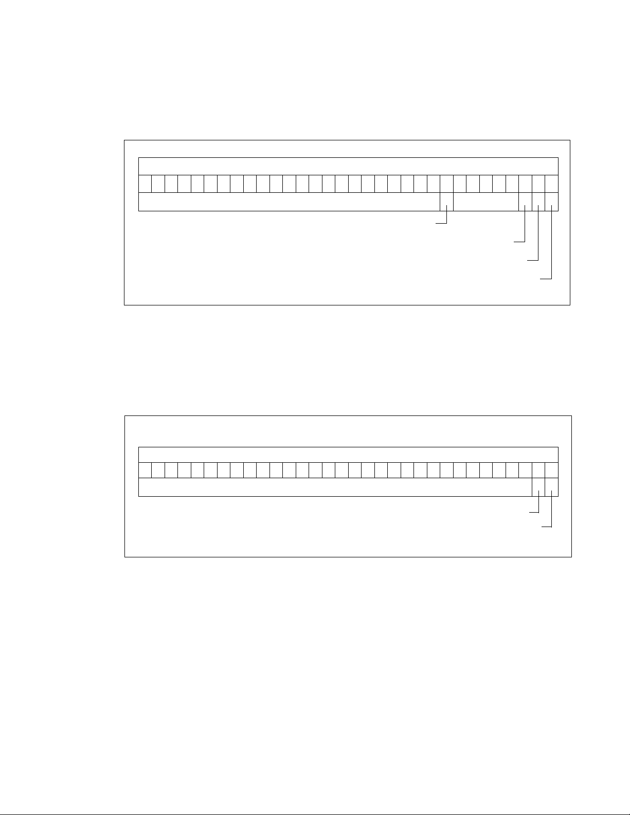
Figure A-17 RCIM III POSIX Clock Status/Control Register (PCSC)
Bits
31 30 29 28 27 26 25 24 23 22 21 20 19 18 17 16 15 14 13 12 11 10 9 8 7 6 5 4 3 2 1 0
Reserved Reserved
Cable Enable (R)
Local Enable (R/W)
Select Cable Enable (R/W)
Select Cable Clock (R/W)
Bits
31 30 29 28 27 26 25 24 23 22 21 20 19 18 17 16 15 14 13 12 11 10 9 8 7 6 5 4 3 2 1 0
Reserved
Skip Time (W)
Add Time (W)
This register provides status and control of the POSIX clock.
Offset: 1110
Registers
Figure A-18 RCIM III POSIX Clock Skip/Add Time Register (PCSAT)
This register skips/adds time to the POSIX clock in 400 nanosecond increments.
Offset: 1114
Artisan Technology Group - Quality Instrumentation ... Guaranteed | (888) 88-SOURCE | www.artisantg.com
A-13
Page 71

RCIM User’s Guide
Bits
31 30 29 28 27 26 25 24 23 22 21 20 19 18 17 16 15 14 13 12 11 10 9 8 7 6 5 4 3 2 1 0
Clock Frequency Adjust
Bits
31 30 29 28 27 26 25 24 23 22 21 20 19 18 17 16 15 14 13 12 11 10 9 8 7 6 5 4 3 2 1 0
RTC timer count value
Bits
31 30 29 28 27 26 25 24 23 22 21 20 19 18 17 16 15 14 13 12 11 10 9 8 7 6 5 4 3 2 1 0
RTC timer repeat value
The clock frequency adjust register is used to control the frequency of the 10 Mhz master clock.
Offset: 1120
The initial RTC timer value is loaded in the RTC timer registers. The current value of the timer is read from
this register. NOTE: Loading this register also loads the RTC Repeat Register for compatibility with RCIM.
Figure A-19 RCIM III Clock Frequency Adjust Register (CFAR)
Figure A-20 RCIM III RTC Timer Registers (RTCT)
Offsets: RTC0T: 2010, RTC1T: 2030, RTC2T: 2050, RTC3T: 2070, RTC4T: 2090, RTC5T: 20B0,
RTC6T: 20D0, RTC7T: 20F0
Figure A-21 RCIM III RTC Repeat Registers (RTCR)
The RTC repeat registers contain the repeat count value.
Offsets: RTC0R: 2014, RTC1R: 2034, RTC2R: 2054, RTC3R: 2074, RTC4R: 2094, RTC5R: 20B4,
RTC6R: 20D4, RTC7R: 20F4
A-14
Artisan Technology Group - Quality Instrumentation ... Guaranteed | (888) 88-SOURCE | www.artisantg.com
Page 72

Registers
Bits
31 30 29 28 27 26 25 24 23 22 21 20 19 18 17 16 15 14 13 12 11 10 9 8 7 6 5 4 3 2 1 0
Reserved
Res.
Reserved
Resolution (R/W)
Repeat (R/W)
Resolution Bit Values
Bits
22 21 20 Description
0 0 0 1 mic rosecond
0 0 1 10 microseconds
0 1 0 100 microseconds
0 1 1 1 millisecond
1 0 0 10 milliseconds
1 0 1 stopped
1 1 0 stopped
1 1 1 stopped
Start (R/W)
(see table below)
Figure A-22 RCIM III RTC Control Registers (RTCC)
This register provides control of the RTCs.
Offsets: RTC0C: 2000, RTC1C: 2020, RTC2C: 2040, RTC3C: 2060, RTC4C: 2080, RTC5C: 20A0,
RTC6C: 20C0, RTC7C: 20E0
A-15
Artisan Technology Group - Quality Instrumentation ... Guaranteed | (888) 88-SOURCE | www.artisantg.com
Page 73

RCIM User’s Guide
Bits
31 30 29 28 27 26 25 24 23 22 21 20 19 18 17 16 15 14 13 12 11 10 9 8 7 6 5 4 3 2 1 0
Reserved PIG
Bits
31 30 29 28 27 26 25 24 23 22 21 20 19 18 17 16 15 14 13 12 11 10 9 8 7 6 5 4 3 2 1 0
Reserved PIG
This register identifies the programmable interrupts.
Offset: 3000
Figure A-24 RCIM III Programmable Interrupt Set/Clear Registers (PIGS, PIGC)
Figure A-23 RCIM III Programmable Interrupt Generator Register (PIG)
Writing to these registers sets/clears the unitary bits in the Programmable Interrupt Register without
affecting the other bits.
Offsets: PIGS: 3010, PIGC: 3020
A-16
Artisan Technology Group - Quality Instrumentation ... Guaranteed | (888) 88-SOURCE | www.artisantg.com
Page 74

Registers
31 30 29 28 27 26 25 24 23 22 21 20 19 18 17 16 15 14 13 12 11 10 9 8 7 6 5 4 3 2 1 0
Reserved
Bits
Count (R)
31 30 29 28 27 26 25 24 23 22 21 20 19 18 17 16 15 14 13 12 11 10 9 8 7 6 5 4 3 2 1 0
Reserved Reserved
Bits
Receive Head Pointer (R)
Receive Tail Pointer
Figure A-25 RCIM III SPI Count Register (SCR)
The SPI (serial peripheral interface) count register contains the count for SPI transfers. The SPI interface is
used to program the FPGA serial prom.
Offset: 3100
Figure A-26 RCIM III GPS Receive Pointers (GRXP)
The GPS receive pointers are used for communication with the optional GPS module.
Offset: 3200
Artisan Technology Group - Quality Instrumentation ... Guaranteed | (888) 88-SOURCE | www.artisantg.com
A-17
Page 75

RCIM User’s Guide
31 30 29 28 27 26 25 24 23 22 21 20 19 18 17 16 15 14 13 12 11 10 9 8 7 6 5 4 3 2 1 0
Reserved Reserved
Bits
T ransmit Tail Pointer (R)T ransmit Head Pointer
31 30 29 28 27 26 25 24 23 22 21 20 19 18 17 16 15 14 13 12 11 10 9 8 7 6 5 4 3 2 1 0
Bits
Reserved
Enable GPS External Communication
Enable UART Loopback
The GPS transmit pointers are used for communication with the optional GPS module.
Offset: 3204
Figure A-27 RCIM III GPS Transmit Pointers (GTXP)
Figure A-28 RCIM III GPS Debug Control Register (GDCR)
The GPS debug control register contains bits used during testing and debug. Setting any of these bits will
disable RCIM communication with the GPS module.
Offset: 3208
A-18
Artisan Technology Group - Quality Instrumentation ... Guaranteed | (888) 88-SOURCE | www.artisantg.com
Page 76

Registers
31 30 29 28 27 26 25 24 23 22 21 20 19 18 17 16 15 14 13 12 11 10 9 8 7 6 5 4 3 2 1 0
Reserved
Bits
Parity Error
Short Start
Frame Error
Bits
31 30 29 28 27 26 25 24 23 22 21 20 19 18 17 16 15 14 13 12 11 10 9 8 7 6 5 4 3 2 1 0
SPI Data Buffer
Bits
31 30 29 28 27 26 25 24 23 22 21 20 19 18 17 16 15 14 13 12 11 10 9 8 7 6 5 4 3 2 1 0
GPS Receive Data Buffer
Figure A-29 RCIM III GPS Communication Error Register (GCER)
The GPS communication error register contains information regarding communication errors with the GPS
module.
Any write to this register will reset the communication interface to the GPS module.
Offset: 320C
Figure A-30 RCIM III SPI Data Buffer (SDB)
This is the SPI Data buffer.
Offset: 3800 to 3FFF
Figure A-31 RCIM III GPS Receive Data Buffer (GRDB)
This is the GPS receive data buffer.
Offset: 4000 to 47FF
Artisan Technology Group - Quality Instrumentation ... Guaranteed | (888) 88-SOURCE | www.artisantg.com
A-19
Page 77

RCIM User’s Guide
Bits
31 30 29 28 27 26 25 24 23 22 21 20 19 18 17 16 15 14 13 12 11 10 9 8 7 6 5 4 3 2 1 0
GPS Transmit Data Buffer
This is the GPS trasmit data buffer.
Offset: 4800 to 4FFF
Figure A-32 RCIM III GPS Transmit Data Buffer (GRDB)
A-20
Artisan Technology Group - Quality Instrumentation ... Guaranteed | (888) 88-SOURCE | www.artisantg.com
Page 78

Registers
RCIM II Registers 1
This section contains the address map and registers on the RCIM II board.
RCIM II Address Map 1
Address Function
0xXXXX0000 Board Status/Control Register (BSCR)
0xXXXX0004
0xXXXX0010 Interrupt Enable Register #1 (IER1)
0xXXXX0014 Interrupt Enable Register #2 (IER2)
0xXXXX0020 Interrupt Request Register #1 (IRR1) (Write Only)
0xXXXX0024 Interrupt Request Register #2 (IRR2) (Write Only)
0xXXXX0020 Interrupt Pending Register #1 (IPR1) (Read Only)
0xXXXX0024 Interrupt Pending Register #2 (IPR2) (Read Only)
0xXXXX0030 Interrupt Clear Register #1 (ICR1)
0xXXXX0034 Interrupt Clear Register #2 (ICR2)
0xXXXX0040 Interrupt Arm Register #1 (IAR1)
0xXXXX0044 Interrupt Arm Register #2 (IAR2)
0xXXXX0050 Interrupt Select Level Register #1 (ISLR1)
0xXXXX0054 Interrupt Select Level Register #2 (ISLR2)
0xXXXX0060 Interrupt Select Polarity Register #1 (ISPR1)
0xXXXX0064 Interrupt Select Polarity Register #2 (ISPR2)
0xXXXX0070 External Interrupt Routing Register #1 (EIRR1)
0xXXXX0074 External Interrupt Routing Register #2 (EIRR2)
0xXXXX0078 External Interrupt Routing Register #3 (EIRR3)
0xXXXX0080 Cable Interrupt Routing Register #1 (CIRR1)
0xXXXX0084 Cable Interrupt Routing Register #2 (CIRR2)
0xXXXX0088 Cable Interrupt Routing Register #3 (CIRR3)
0xXXXX00A0 PCI Interrupt A Routing Register #1 (PARR1)
0xXXXX00A4 PCI Interrupt A Routing Register #2 (PARR2)
0xXXXX00B0 PCI Interrupt B Routing Register #1 (PBRR1)
0xXXXX00B4 PCI Interrupt B Routing Register #2 (PBRR2)
0xXXXX00C0 PCI Interrupt C Routing Register #1 (PCRR1)
0xXXXX00C4 PCI Interrupt C Routing Register #2 (PCRR2)
0xXXXX00D0 PCI Interrupt D Routing Register #1 (PDRR1)
0xXXXX00D4 PCI Interrupt D Routing Register #2 (PDRR2)
0xXXXX0100 DDS Adjust Register #1 (DDS)
0xXXXX0200 PPS Snapshot Register (PPS) (Read Only)
0xXXXX0300 GPS Transmit/Receive Register (GPS)
0xXXXX0400 Clear Cable Errors (CCERR) (Write Only)
0xXXXX1000 Tick Clock Upper (TCU)
0xXXXX1008 Tick Clock Lower (TCL)
0xXXXX1010 Tick Clock Status/Control (TCSC)
Firmware Rev/Options Present Register (FWOP)
Artisan Technology Group - Quality Instrumentation ... Guaranteed | (888) 88-SOURCE | www.artisantg.com
A-21
Page 79

RCIM User’s Guide
Address Function
0xXXXX1100 POSIX Clock Seconds (PCS)
0xXXXX1108 POSIX Clock Nanoseconds (PCN)
0xXXXX1110 POSIX Clock Status/Control (PCSC)
0xXXXX1114 POSIX Clock Skip/Add Time (PCSAT) (Write Only)
0xXXXX2000 RTC #0 Control (RTC0C)
0xXXXX2010 RTC #0 Timer (RTC0T)
0xXXXX2014 RTC #0 Repeat (RTC0R)
0xXXXX2020 RTC #1 Control (RTC1C)
0xXXXX2030 RTC #1 Timer (RTC1T)
0xXXXX2034 RTC #1 Repeat (RTC1R)
0xXXXX2040 RTC #2 Control (RTC2C)
0xXXXX2050 RTC #2 Timer (RTC2T)
0xXXXX2054 RTC #2 Repeat (RTC2R)
0xXXXX2060 RTC #3 Control (RTC3C)
0xXXXX2070 RTC #3 Timer (RTC3T)
0xXXXX2074 RTC #3 Repeat (RTC3R)
0xXXXX2080 RTC #4 Control (RTC4C)
0xXXXX2090 RTC #4 Timer (RTC4T)
0xXXXX2094 RTC #4 Repeat (RTC4R)
0xXXXX20A0 RTC #5 Control (RTC5C)
0xXXXX20B0 RTC #5 Timer (RTC5T)
0xXXXX20B4 RTC #5 Repeat (RTC5R)
0xXXXX20C0 RTC #6 Control (RTC6C)
0xXXXX20D0 RTC #6 Timer (RTC6T)
0xXXXX20D4 RTC #6 Repeat (RTC6R)
0xXXXX20E0 RTC #7 Control (RTC7C)
0xXXXX20F0 RTC #7 Timer (RTC7T)
0xXXXX20F4 RTC #7 Repeat (RTC7R)
0xXXXX3000 Programmable Interrupt Generator (PIG)
0xXXXX3010 Programmable Interrupt Generator Set (PIGS) (Write Only)
0xXXXX3020 Programmable Interrupt Generator Clear (PIGC) (Write Only)
A-22
Artisan Technology Group - Quality Instrumentation ... Guaranteed | (888) 88-SOURCE | www.artisantg.com
Page 80

Registers
Bits
31 30 29 28 27 26 25 24 23 22 21 20 19 18 17 16 15 14 13 12 11 10 9 8 7 6 5 4 3 2 1 0
RCIM Version = 0001 (R) R R
Res.
Cable Clock Stop (R/W) (diag)
Cable Clock Missin g (R )
RCIM Mode Bit Values
Bits
10 Description
Input
Cable
Output
Cable
Cable
Clock
11 Stand-alone Master RCIM Open Open Inactive
10 Master RCIM Open Connected Sourcing
01 Last Slave RCIM Connected Connected Receiving
00 Pass-thru Slave RCIM Connected Open Receiving
GPS RX Buffer Full (R)
Cable Clock Enable (R/W)
GPS TX Buffer Empty (R)
RTC Select Cable Clock (R/W)
Input Cable Error (R)
Input Cable Unsynced (R)
Output Cable Error (R)
Output Cable Unsynced (R)
RCIM Mode (R)
(see table below)
RCIM II Registers 1
RCIM II registers are illustrated in this section.
NOTE: Unless otherwise stated, a bit value of 1=on; 0=off.
Figure A-33 RCIM II Board Status/Control Register (BSCR)
This register provides status and control of certain features of the RCIM II board.
Offset: 0000
Artisan Technology Group - Quality Instrumentation ... Guaranteed | (888) 88-SOURCE | www.artisantg.com
A-23
Page 81

RCIM User’s Guide
31 30 29 28 27 26 25 24 23 22 21 20 19 18 17 16 15 14 13 12 11 10 9 8 7 6 5 4 3 2 1 0
Reserved Reserved
Firmware Revision (R)
External Oscillator Present (R)
Optional Oscillator Present (R)
GPS Present (R)
Bits
This register provides information on what options are present on this RCIM board and the firmware
revision.
Offset: 00004
Figure A-34 RCIM II Firmware Revision/Options Present Register (FWOP)
A-24
Artisan Technology Group - Quality Instrumentation ... Guaranteed | (888) 88-SOURCE | www.artisantg.com
Page 82

Registers
Register #1
Bits
31 30 29 28 27 26 25 24 23 22 21 20 19 18 17 16 15 14 13 12 11 10 9 8 7 6 5 4 3 2 1 0
CI AUX Reserved EI RTC
7 6 5 4 3 2 1 0 3 2 1 0 7 6 5 4 3 2 1 0 7 6 5 4 3 2 1 0
CI = Cable Interrupt
AUX = Auxiliary Interrupt (GPS)
EI = External Interrupt
RTC = RTC Interrupt
Register #2
Bits
31 30 29 28 27 26 25 24 23 22 21 20 19 18 17 16 15 14 13 12 11 10 9 8 7 6 5 4 3 2 1 0
Reserved CI Reserved EI Reserved
11 10 9 8 11 10 9 8
AUX2 = GPS_BX_FULL
AUX1 = GPS_TX_EMPTY
AUX3 =
Reserved
AUX0 = GPS_PPS
Figure A-35 RCIM II Interrupt Enable/Request/Pending/Clear/Arm/Level/Polarity Regis ters
(IER, IRR, IPR, ICR, IAR, ISLR, ISPR)
The enable registers (IER) enable the selected interrupts.
The request registers (IRR) are software driven requests of the selected interrupts.
The pending registers (IPR) are pending requests.
The clear registers (ICR) clear the selected interrupts.
The arm registers (IAR) arm the selected interrupts for edge triggering.
The level registers (ISLR) set level (1) or edge (0) for the selected interrupts.
The polarity registers (ISPR) set polarity high (1) or low (0) for the selected interrupts.
Offsets: IER1: 0010, IER2: 0014, IRR1/IPR1: 0020, IRR2/IPR2: 0024, ICR1: 0030, ICR2: 0034,
IAR1: 0040, IAR2: 0044, ISLR1: 0050, ISLR2: 0054, ISPR1: 0060, ISPR2: 0064
Artisan Technology Group - Quality Instrumentation ... Guaranteed | (888) 88-SOURCE | www.artisantg.com
A-25
Page 83

RCIM User’s Guide
External Interrupt Number Register Number
Bits
31 30 29 28 27 26 25 24 23 22 21 20 19 18 17 16 15 14 13 12 11 10 9 8 7 6 5 4 3 2 1 0
Res.
3
Res.
2
Res.
1
Res.
0
#1
7
6
54#2
11 10
98#3
5 4 3 2 1 0 5 4 3 2 1 0 5 4 3 2 1 0 5 4 3 2 1 0
Value Description
0x00 Reserved
0x01 Reserved
0x02 Reserved
0x03 Reserved
0x04 RTC 0
0x05 RTC 1
0x06 RTC 2
0x07 RTC 3
0x08 Edge Interrupt 0
0x09 Edge Interrupt 1
0x0A Edge Interrupt 2
0x0B Edge Interrupt 3
0x0C PIG 0
0x0D PIG 1
0x0E PIG 2
0x0F PIG 3
0x10 Cable Interrupt 0
0x11 Cable Interrupt 1
0x12 Cable Interrupt 2
0x13 Cable Interrupt 3
0x14 Cable Interrupt 4
0x15 Cable Interrupt 5
0x16 Cable Interrupt 6
0x17 Cable Interrupt 7
0x18 Cable Interrupt 8
0x19 Cable Interrupt 9
0x1A Cable Interrupt 10
0x1B Cable Interrupt 11
0x1C Reserved
0x1D Reserved
0x1E Reserved
0x1F Reserved
Value Description
0x20 GPS_PPS
0x21 Reserved
0x22 Reserved
0x23 Reserved
0x24 RTC 4
0x25 RTC 5
0x26 RTC 6
0x27 RTC 7
0x28 Edge Interrupt 4
0x29 Edge Interrupt 5
0x2A Edge Interrupt 6
0x2B Edge Interrupt 7
0x2C PIG 4
0x2D PIG 5
0x2E PIG 6
0x2F PIG 7
0x30 Reserved
0x31 Reserved
0x32 Reserved
0x33 Reserved
0x34 Reserved
0x35 Reserved
0x36 Reserved
0x37 Reserved
0x38 Edge Interrupt 8
0x39 Edge Interrupt 9
0x3A Edge Interrupt 10
0x3B Edge Interrupt 11
0x3C PIG 8
0x3D PIG 9
0x3E PIG 10
0x3F PIG 11
Figure A-36 RCIM II External Interrupt Routing Registers (EIRR)
The external interrupt routing registers route selected interrupts to the external interrupt connector.
Offset: EIRR1: 0070, EIRR2: 0074, EIRR3: 0078
A-26
Artisan Technology Group - Quality Instrumentation ... Guaranteed | (888) 88-SOURCE | www.artisantg.com
Page 84

Figure A-37 RCIM II Cable Interrupt Routing Registers (CIRR)
Cable Interrupt Register 1
Bits
31 30 29 28 27 26 25 24 23 22 21 20 19 18 17 16 15 14 13 12 11 10 9 8 7 6 5 4 3 2 1 0
7
6
5
4
3
2
1
0
7 6 5 4 3 2 1 0 7 6 5 4 3 2 1 0 7 6 5 4 3 2 1 0 7 6 5 4 3 2 1 0
Cable Interrupt Register 2
Bits
31 30 29 28 27 26 25 24 23 22 21 20 19 18 17 16 15 14 13 12 11 10 9 8 7 6 5 4 3 2 1 0
Reserved 11
10
9
8
3 2 1 0 3 2 1 0 3 2 1 0 3 2 1 0
Cable Interrupt Number
Value Description Value Description Value Description
0x00 Reserved 0x10 Reserved 0x20 GPS_PPS
0x01 Reserved 0x11 Reserved
0x21
Reserved
0x02 Reserved 0x12 Reserved | |
0x03 Reserved 0x13 Reserved 0x27 Reserved
0x04 RTC 0 0x14 RTC 4 0x28 Edge Interrupt 8
0x05 RTC 1 0x15 RTC 5 0x29 Edge Interrupt 9
0x06 RTC 2 0x16 RTC 6 0x2A Edge Interrupt 10
0x07 RTC 3 0x17 RTC 7 0x2B Edge Interrupt 11
0x08 Edge Interrupt 0 0x18 Edge Interrupt 4 0x2C PIG 8
0x09 Edge Interrupt 1 0x19 Edge Interrupt 5 0x2D PIG 9
0x0A Edge Interrupt 2 0x1A Edge Interrupt 6 0x2E PIG 10
0x0B Edge Interrupt 3 0x1B Edge Interrupt 7 0x2F PIG 11
0x0C PIG 0 0x1C PIG 4 0x30 Reserved
0x0D PIG 1 0x1D PIG 5 | |
0x0E PIG 2 0x1E P IG 6 | |
0x0F PIG 3 0x1F PIG 7 0x3F Reserved
Cable Interrupt Register 3
Bits
31 30 29 28 27 26 25 24 23 22 21 20 19 18 17 16 15 14 13 12 11 10 9 8 7 6 5 4 3 2 1 0
Reserved
1110987654
3
210
5 4 5 4 5 4 5 4 5 4 5 4 5 4 5 4 5 4 5 4 5 4 5 4
The cable interrupt routing registers route selected interrupts to the RCIM interconnecting cable.
Offsets: CIRR1: 0080, CIRR2: 0084, CIRR3: 0088
Registers
Artisan Technology Group - Quality Instrumentation ... Guaranteed | (888) 88-SOURCE | www.artisantg.com
A-27
Page 85

RCIM User’s Guide
PCI Interrupt Routing Register 1 (PARR1, PBRR1, PCRR1, PDRR1)
Bits
31 30 29 28 27 26 25 24 23 22 21 20 19 18 17 16 15 14 13 12 11 10 9 8 7 6 5 4 3 2 1 0
Reserved EI Reserved RTC
11 10 9 8 7 6 5 4 3 2 1 0 7 6 5 4 3 2 1 0
PCI Interrupt Routing Register 2 (PARR2, PBRR2, PCRR2, PDRR2)
Bits
31 30 29 28 27 26 25 24 23 22 21 20 19 18 17 16 15 14 13 12 11 10 9 8 7 6 5 4 3 2 1 0
Reserved AUX Reserved CI
3 2 1 0 11 10 9 8 7 6 5 4 3 2 1 0
Bits
31 30 29 28 27 26 25 24 23 22 21 20 19 18 17 16 15 14 13 12 11 10 9 8 7 6 5 4 3 2 1 0
DDS
Figure A-38 RCIM II PCI Interrupt Routing Registers (PARR, PBRR, PCRR, PDRR)
Setting a bit in a PCI interrupt routing register routes selected interrupts to the designated PCI interrupt. The
default power-up value is everything routed to PCI A. Setting bits in multiple registers will drive multiple
PCI interrupt lines.
Offsets: PARR1: 00A0, PARR2: 00A4, PBRR1: 00B0, PBRR2: B4, PCRR1: 00C0, PCRR2: 00C4,
PDRR1: 00D0, PDRR2 00D4
Figure A-39 RCIM II DDS Adjust Register (DDS)
Writing to the Direct Digital Synthesizer Adjust register loads the 32-bit frequency control word into the
onboard AD9851 DDS.
Offset: 0100
A-28
Artisan Technology Group - Quality Instrumentation ... Guaranteed | (888) 88-SOURCE | www.artisantg.com
Page 86

Registers
Bits
31 30 29 28 27 26 25 24 23 22 21 20 19 18 17 16 15 14 13 12 11 10 9 8 7 6 5 4 3 2 1 0
PPS Snapshot
Bits
31 30 29 28 27 26 25 24 23 22 21 20 19 18 17 16 15 14 13 12 11 10 9 8 7 6 5 4 3 2 1 0
GPS T ransmit/Receive
Bits
31 30 29 28 27 26 25 24 23 22 21 20 19 18 17 16 15 14 13 12 11 10 9 8 7 6 5 4 3 2 1 0
Clear Cable Errors
Figure A-40 RCIM II PPS Snapshot Register (PPS)
The PPS Snapshot register contains a snapshot of the nanoseconds field and two bits of the seconds field of
the POSIX clock. The snapshot is taken every time the GPS PPS signal occurs.
Offset: 0200
Figure A-41 RCIM II GPS Transmit/Receive Register (GPS)
The GPS Transmit/Receive register is used for serial communication with the GPS module via the PCI bus
interface.
Offset: 0300
Figure A-42 RCIM II Clear Cable Errors Register (CCERR)
This is a Write Only register that clears any reported cable errors. The data field is don’t care.
Offset: 0400
Artisan Technology Group - Quality Instrumentation ... Guaranteed | (888) 88-SOURCE | www.artisantg.com
A-29
Page 87

RCIM User’s Guide
Bits
31 30 29 28 27 26 25 24 23 22 21 20 19 18 17 16 15 14 13 12 11 10 9 8 7 6 5 4 3 2 1 0
Tick Clock upper 32 bits
Bits
31 30 29 28 27 26 25 24 23 22 21 20 19 18 17 16 15 14 13 12 11 10 9 8 7 6 5 4 3 2 1 0
Tick Clock lower 32 bits
Bits
31 30 29 28 27 26 25 24 23 22 21 20 19 18 17 16 15 14 13 12 11 10 9 8 7 6 5 4 3 2 1 0
Reserved Reserved
Cable Enable (R)
No Reset When Disabled (R/W)
Local Enable (R/W)
Select Cable Enable (R/W)
Select Cable Clock (R/W)
This register contains the upper 32 bits of the tick clock.
Offset: 1000
This register contains the lower 32 bits of the tick clock.
Offset: 1008
Figure A-43 RCIM II Tick Clock Upper Register (TCU)
Figure A-44 RCIM II Tick Clock Lower Register (TCL)
Figure A-45 RCIM II Tick Clock Status/Control Register (TCSC)
This register provides status and control of the tick clock.
Offset: 1010
A-30
Artisan Technology Group - Quality Instrumentation ... Guaranteed | (888) 88-SOURCE | www.artisantg.com
Page 88

Figure A-46 RCIM II POSIX Clock Seconds Register (PCS)
Bits
31 30 29 28 27 26 25 24 23 22 21 20 19 18 17 16 15 14 13 12 11 10 9 8 7 6 5 4 3 2 1 0
POSIX Clock seconds
Bits
31 30 29 28 27 26 25 24 23 22 21 20 19 18 17 16 15 14 13 12 11 10 9 8 7 6 5 4 3 2 1 0
POSIX Clock nanoseconds
This register contains the POSIX clock seconds.
Offset: 1100
Figure A-47 RCIM II POSIX Clock Nanoseconds Register (PCN)
This register contains the POSIX clock nanoseconds.
Offset: 1108
Registers
Artisan Technology Group - Quality Instrumentation ... Guaranteed | (888) 88-SOURCE | www.artisantg.com
A-31
Page 89

RCIM User’s Guide
Bits
31 30 29 28 27 26 25 24 23 22 21 20 19 18 17 16 15 14 13 12 11 10 9 8 7 6 5 4 3 2 1 0
Reserved Reserved
Cable Enable (R)
Local Enable (R/W)
Select Cable Enable (R/W)
Select Cable Clock (R/W)
Bits
31 30 29 28 27 26 25 24 23 22 21 20 19 18 17 16 15 14 13 12 11 10 9 8 7 6 5 4 3 2 1 0
Reserved
Skip Time (W)
Add Time (W)
This register provides status and control of the POSIX clock.
Offset: 1110
Figure A-48 RCIM II POSIX Clock Status/Control Register (PCSC)
Figure A-49 RCIM II POSIX Clock Skip/Add Time Register (PCSAT)
This register skips/adds time to the POSIX clock in 400 nanosecond increments.
Offset: 1114
A-32
Artisan Technology Group - Quality Instrumentation ... Guaranteed | (888) 88-SOURCE | www.artisantg.com
Page 90

Registers
Bits
31 30 29 28 27 26 25 24 23 22 21 20 19 18 17 16 15 14 13 12 11 10 9 8 7 6 5 4 3 2 1 0
RTC timer count value
Bits
31 30 29 28 27 26 25 24 23 22 21 20 19 18 17 16 15 14 13 12 11 10 9 8 7 6 5 4 3 2 1 0
RTC timer repeat value
Figure A-50 RCIM II RTC Timer Registers (RTCT)
The initial RTC timer value is loaded in the RTC timer registers. The current value of the timer is read from
this register. NOTE: Loading this register also loads the RTC Repeat Register for compatibility with RCIM.
Offsets: RTC0T: 2010, RTC1T: 2030, RTC2T: 2050, RTC3T: 2070, RTC4T: 2090, RTC5T: 20B0,
RTC6T: 20D0, RTC7T: 20F0
Figure A-51 RCIM II RTC Repeat Registers (RTCR)
The RTC repeat registers contain the repeat count value.
Offsets: RTC0R: 2014, RTC1R: 2034, RTC2R: 2054, RTC3R: 2074, RTC4R: 2094, RTC5R: 20B4,
RTC6R: 20D4, RTC7R: 20F4
Artisan Technology Group - Quality Instrumentation ... Guaranteed | (888) 88-SOURCE | www.artisantg.com
A-33
Page 91

RCIM User’s Guide
Bits
31 30 29 28 27 26 25 24 23 22 21 20 19 18 17 16 15 14 13 12 11 10 9 8 7 6 5 4 3 2 1 0
Reserved
Res.
Reserved
Resolution (R/W)
Repeat (R/W)
Resolution Bit Values
Bits
22 21 20 Description
0 0 0 1 mic rosecond
0 0 1 10 microseconds
0 1 0 100 microseconds
0 1 1 1 millisecond
1 0 0 10 milliseconds
1 0 1 stopped
1 1 0 stopped
1 1 1 stopped
Start (R/W)
(see table below)
This register provides control of the RTCs.
Offsets: RTC0C: 2000, RTC1C: 2020, RTC2C: 2040, RTC3C: 2060, RTC4C: 2080, RTC5C: 20A0,
RTC6C: 20C0, RTC7C: 20E0
Figure A-52 RCIM II RTC Control Registers (RTCC)
A-34
Artisan Technology Group - Quality Instrumentation ... Guaranteed | (888) 88-SOURCE | www.artisantg.com
Page 92

Registers
Bits
31 30 29 28 27 26 25 24 23 22 21 20 19 18 17 16 15 14 13 12 11 10 9 8 7 6 5 4 3 2 1 0
Reserved PIG
Bits
31 30 29 28 27 26 25 24 23 22 21 20 19 18 17 16 15 14 13 12 11 10 9 8 7 6 5 4 3 2 1 0
Reserved PIG
Figure A-53 RCIM II Programmable Interrupt Generator Register (PIG)
This register identifies the programmable interrupts.
Offset: 3000
Figure A-54 RCIM II Programmable Interrupt Set/Clear Registers (PIGS, PIGC)
Writing to these registers sets/clears the unitary bits in the Programmable Interrupt Register without
affecting the other bits.
Offsets: PIGS: 3010, PIGC: 3020
Artisan Technology Group - Quality Instrumentation ... Guaranteed | (888) 88-SOURCE | www.artisantg.com
A-35
Page 93

RCIM User’s Guide
RCIM I Registers 1
This section contains the address map and registers on the RCIM I board.
RCIM I Address Map 1
Address Function
0xXXXX0000 Board Status/Control Register (BSCR)
0xXXXX0010 Interrupt Enable Register (IER)
0xXXXX0020 Interrupt Request Register (IRR) (Write Only)
0xXXXX0020 Interrupt Pending Register (IPR) (Read Only)
0xXXXX0030 Interrupt Clear Register (ICR)
0xXXXX0040 Interrupt Arm Register (IAR)
0xXXXX0050 Interrupt Select Level Register (ISLR)
0xXXXX0060 Interrupt Select Polarity Register (ISPR)
0xXXXX0070 External Interrupt Routing Register (EIRR)
0xXXXX0080 Cable Interrupt Routing Register (CIRR)
0xXXXX1000 Tick Clock Upper (TCU)
0xXXXX1008 Tick Clock Lower (TCL)
0xXXXX1010 Tick Clock Status/Control (TCSC)
0xXXXX1100 POSIX Clock Seconds (PCS)
0xXXXX1108 POSIX Clock Nanoseconds (PCN)
0xXXXX1110 POSIX Clock Status/Control (PCSC)
0xXXXX2000 RTC #0 Control
0xXXXX2010 RTC #0 Timer
0xXXXX2020 RTC #1 Control
0xXXXX2030 RTC #1 Timer
0xXXXX2040 RTC #2 Control
0xXXXX2050 RTC #2 Timer
0xXXXX2060 RTC #3 Control
0xXXXX2070 RTC #3 Timer
0xXXXX3000 Programmable Interrupt Generator (PIG)
A-36
Artisan Technology Group - Quality Instrumentation ... Guaranteed | (888) 88-SOURCE | www.artisantg.com
Page 94

Registers
Bits
31 30 29 28 27 26 25 24 23 22 21 20 19 18 17 16 15 14 13 12 11 10 9 8 7 6 5 4 3 2 1 0
RCIM Version (R) Reserved Res. Res.
Cable Clock Stop (R/W) (diag)
Cable Clock Enable (R/W)
Cable Clock Missing (R)
RCIM Mode (R)
RCIM Mode Bit Values
Bits
1 0
Description
Input
Cable
Output
Cable
Cable
Clock
Cable
Termination
0 0 Master RCIM Open Connected Sourcing On
0 1 Pass-thru Slave RCIM Connected Connected Receiving Off
1 0 Last Slave RCIM Connected Open Receiving On
1 1 Stand-alone Master RCIM Open Open Inactive On
(see table below)
RCIM I Registers 1
RCIM Iregisters are illustrated in this section.
NOTE: Unless otherwise stated, a bit value of 1=on; 0=off.
Figure A-55 RCIM I Board Status/Control Register (BSCR)
This register provides status and control of certain features of the RCIM I board.
Offset: 0000
Artisan Technology Group - Quality Instrumentation ... Guaranteed | (888) 88-SOURCE | www.artisantg.com
A-37
Page 95

RCIM User’s Guide
Bits
31 30 29 28 27 26 25 24 23 22 21 20 19 18 17 16 15 14 13 12 11 10 9 8 7 6 5 4 3 2 1 0
CI Reserved PIG Reserved EI Reserved RTC
7 6 5 4 3 2 1 0 3 2 1 0 3 2 1 0 3 2 1 0
CI = Cable Interrupt
PIG = Programmable Interrupt Generator
EI = External Interrupt
RTC = RTC Interrupt
Figure A-56 RCIM I Interrupt Enable/Request/Pending/Clear/ARM/Level/Polarity Registers
The enable register (IER) enables the selected interrupt.
The request register (IRR) is a software driven request of the selected interrupt.
The pending register (IPR) is a pending request.
The clear register (ICR) clears the selected interrupt.
The arm register (IAR) arms the selected interrupt for edge triggering.
The level register (ISLR) sets level (1) or edge (0) for the selected interrupt.
The polarity register (ISPR) sets polarity high (1) or low (0) for the selected interrupt.
Offsets: IER: 0010, IRR/IPR: 0020, ICR: 0030, IAR: 0040, ISLR: 0050, ISPR: 0060
(IER, IRR, IPR, ICR, IAR, ISLR, ISPR)
A-38
Artisan Technology Group - Quality Instrumentation ... Guaranteed | (888) 88-SOURCE | www.artisantg.com
Page 96

Figure A-57 RCIM I External Interrupt Routing Register (EIRR)
External Interrupt Number
Bits
31 30 29 28 27 26 25 24 23 22 21 20 19 18 17 16 15 14 13 12 11 10 9 8 7 6 5 4 3 2 1 0
3 2 1 0
7 6 5 4 3 2 1 0 7 6 5 4 3 2 1 0 7 6 5 4 3 2 1 0 7 6 5 4 3 2 1 0
Value Description
0x00 None
0x01 Reserved
0x02 Reserved
0x03 Reserved
0x04 RTC 0
0x05 RTC 1
0x06 RTC 2
0x07 RTC 3
0x08 Edge Interrupt 0
0x09 Edge Interrupt 1
0x0A Edge Interrupt 2
0x0B Edge Interrupt 3
0x0C PIG 0
0x0D PIG 1
0x0E PIG 2
0x0F PIG 3
0x10 Cable Interrupt 0
0x11 Cable Interrupt 1
0x12 Cable Interrupt 2
0x13 Cable Interrupt 3
0x14 Cable Interrupt 4
0x15 Cable Interrupt 5
0x16 Cable Interrupt 6
0x17 Cable Interrupt 7
0x18 Reserved
::
0xFF Reserved
The external interrupt routing register routes selected interrupts to the external interrupt connector.
Offset: 0070
Registers
A-39
Artisan Technology Group - Quality Instrumentation ... Guaranteed | (888) 88-SOURCE | www.artisantg.com
Page 97

RCIM User’s Guide
Cable Interrupt Number
Bits
31 30 29 28 27 26 25 24 23 22 21 20 19 18 17 16 15 14 13 12 11 10 9 8 7 6 5 4 3 2 1 0
7 6 5 4 3 2 1 0
3 2 1 0 3 2 1 0 3 2 1 0 3 2 1 0 3 2 1 0 3 2 1 0 3 2 1 0 3 2 1 0
Value Description
0x0 None
0x1 Reserved
0x2 Reserved
0x3 Reserved
0x4 RTC 0
0x5 RTC 1
0x6 RTC 2
0x7 RTC 3
0x8 Edge Interrupt 0
0x9 Edge Interrupt 1
0xA Edge Interrupt 2
0xB Edge Interrupt 3
0xC PIG 0
0xD PIG 1
0xE PIG 2
0xF PIG 3
The cable interrupt routing register routes selected interrupts to the RCIM I interconnecting cable.
Offset: 0080
Figure A-58 RCIM I Cable Interrupt Routing Register (CIRR)
A-40
Artisan Technology Group - Quality Instrumentation ... Guaranteed | (888) 88-SOURCE | www.artisantg.com
Page 98
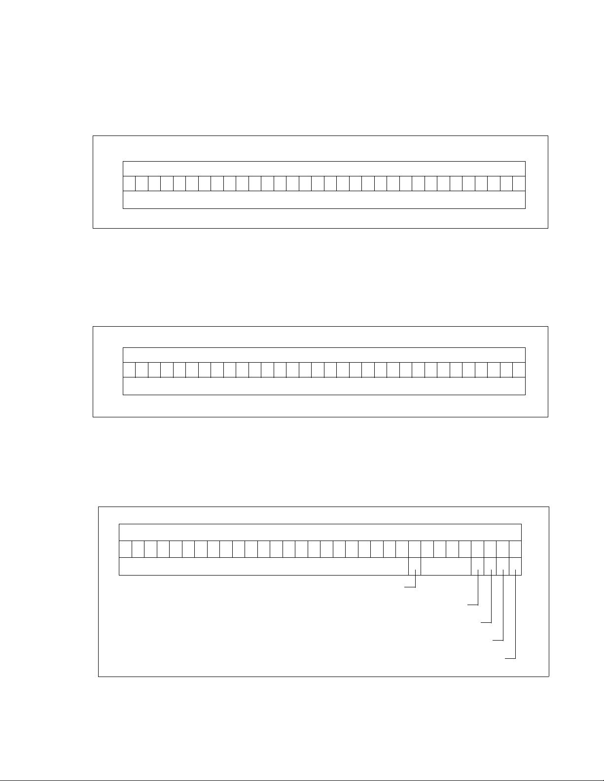
Figure A-59 RCIM I Tick Clock Upper Register (TCU)
Bits
31 30 29 28 27 26 25 24 23 22 21 20 19 18 17 16 15 14 13 12 11 10 9 8 7 6 5 4 3 2 1 0
Tick Clock upper 32 bits
Bits
31 30 29 28 27 26 25 24 23 22 21 20 19 18 17 16 15 14 13 12 11 10 9 8 7 6 5 4 3 2 1 0
Tick Clock lower 32 bits
Bits
31 30 29 28 27 26 25 24 23 22 21 20 19 18 17 16 15 14 13 12 11 10 9 8 7 6 5 4 3 2 1 0
Reserved Reserved
Cable Enable (R)
No Reset When Disabled (R/W)
Local Enable (R/W)
Select Cable Enable (R/W)
Select Cable Clock (R/W)
This register contains the upper 32 bits of the tick clock.
Offset: 1000
Figure A-60 RCIM I Tick Clock Lower Register (TCL)
This register contains the lower 32 bits of the tick clock.
Offset: 1004
Registers
Figure A-61 RCIM I Tick Clock Status/Control Register (TCSC)
This register provides status and control of the tick clock.
Offset: 1010
Artisan Technology Group - Quality Instrumentation ... Guaranteed | (888) 88-SOURCE | www.artisantg.com
A-41
Page 99

RCIM User’s Guide
Bits
31 30 29 28 27 26 25 24 23 22 21 20 19 18 17 16 15 14 13 12 11 10 9 8 7 6 5 4 3 2 1 0
POSIX Clock seconds
Bits
31 30 29 28 27 26 25 24 23 22 21 20 19 18 17 16 15 14 13 12 11 10 9 8 7 6 5 4 3 2 1 0
POSIX Clock nanoseconds
Bits
31 30 29 28 27 26 25 24 23 22 21 20 19 18 17 16 15 14 13 12 11 10 9 8 7 6 5 4 3 2 1 0
Reserved Reserved
Cable Enable (R)
Local Enable (R/W)
Select Cable Enable (R/W)
Select Cable Clock (R/W)
This register contains the POSIX clock seconds.
Offset: 1100
This register contains the POSIX clock nanoseconds.
Offset: 1104
Figure A-62 RCIM I POSIX Clock Seconds Register (PCS)
Figure A-63 RCIM I POSIX Clock Nanoseconds Register (PCN)
Figure A-64 RCIM I POSIX Clock Status/Control Regis ter (PCSC)
This register provides status and control of the POSIX clock.
Offset: 1110
A-42
Artisan Technology Group - Quality Instrumentation ... Guaranteed | (888) 88-SOURCE | www.artisantg.com
Page 100

Figure A-65 RCIM I RTC Control Registers
Bits
31 30 29 28 27 26 25 24 23 22 21 20 19 18 17 16 15 14 13 12 11 10 9 8 7 6 5 4 3 2 1 0
Reserved
Res.
Reserved
Resolution (R/W)
Repeat (R/W)
Resolution Bit Values
Bits
22 21 20
Description
0 0 0 1 mic rosecond
0 0 1 10 microseconds
0 1 0 100 microseconds
0 1 1 1 millisecond
1 0 0 10 milliseconds
1 0 1 stopped
1 1 0 stopped
1 1 1 stopped
Start (R/W)
Bits
31 30 29 28 27 26 25 24 23 22 21 20 19 18 17 16 15 14 13 12 11 10 9 8 7 6 5 4 3 2 1 0
RTC timer count value
This register provides control of the RTCs.
Offsets: RTC #0: 2000, RTC #1: 2020, RTC #2: 2040, RTC #3: 2060
Registers
Figure A-66 RCIM I RTC Timer Registers
The initial RTC timer value is loaded in the RTC timer registers. The current value of the timer is read from
this register.
Offsets: RTC #0: 2010, RTC #1: 2030, RTC #2: 2050, RTC #3: 2070
A-43
Artisan Technology Group - Quality Instrumentation ... Guaranteed | (888) 88-SOURCE | www.artisantg.com
 Loading...