

Page 1
1
1300 650 059 | concoursegolf.com
SMART WHEELS
USER INSTRUCTION MANUAL
Version 3.0
Page 2
1300 650 059 | concoursegolf.com
2
CONGRATULATIONS ON YOUR PURCHASE OF THE CONCOURSE GOLF SMART WHEELS.
Whilst designed to be simple and intuitive to operate, please read the charging instructions prior to
connecting to power for the very first time.
We recommend you read and familiarise yourself with this User Manual prior to operation, to help you get
the most enjoyable ownership experience with your Smart Wheels.
User Instruction Manual | Version 3.0
Page 3
User Instruction Manual | Version 1.71300 650 059 | concoursegolf.com
WE’RE HERE TO HELP
CUSTOMER SUPPORT OR PRODUCT ENQUIRES PLEASE CONTACT CONCOURSE GOLF ON 1300 650 059
OR EMAIL [email protected]
1.0 Product Registration .........................................................4
2.0 What’s Inside - Equipment Check ............................................. 4
3.0 Charging Instructions ........................................................ 5
4.0 Connecting The Smart Wheels To Your Clicgear Push Buggy ....................8
5.0 Connecting The Smart Wheels To Your CBM3 Push Buggy ......................10
6.0 Connecting The Smart Wheels To Other Push Buggy Models ...................11
7.0 Removing your Smart Wheels ................................................12
8.0 Remote Control Function .....................................................13
9.0 Remote Control Mount .......................................................13
10.0 Operating & Power Assited Manual Steering ..................................14
11.0 Important Information .......................................................15
12.0 Warranty & Service ..........................................................15
CONTENTS:
3
Page 4
1300 650 059 | concoursegolf.com
4
IMPORTANT: TO MAXIMISE YOUR BATTERY LIFE, PLEASE READ THE CHARGING INSTRUCTIONS (SECTION 3)
PRIOR TO CONNECTING TO A POWER POINT FOR THE FIRST TIME.
1.0
PRODUCT REGISTRATION
2.0
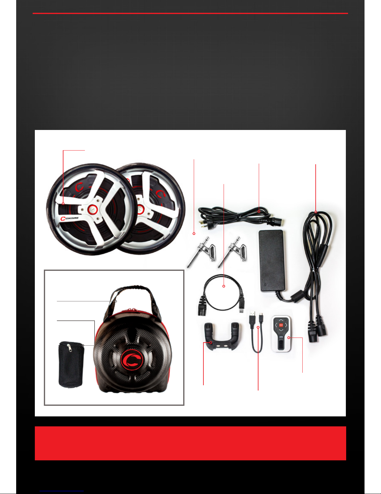
EQUIPMENT CHECK
SMART WHEELS
AXLE CHARGER POWER
CABLE (PART 1)
SOFTWARE
UPGRADE CABLE
CHARGER POWER
CABLE (PART2)
REMOTE CONTROL
CHARGING CABLE
REMOTE
REMOTE
CONTROL
MOUNT
SMART WHEELS
CARRY CASE
REMOTE CONTROL
POUCH
OPTIONAL
To assist with any future software updates and expedite any service enquires throughout the lifetime of your ownership, please ensure
you register your Concourse Smart Wheel purchase online at www.concoursegolf.com
In the unlikely event you may need to complete any warranty returns, the following items will assist with swift service.
• Please retain the carboard box you received your Smart Wheels in for convienient return/shipping.
• Proof of Purchase – Receipt
For details regarding warranty return visit concoursegolf.com or call 1300 650 059
User Instruction Manual | Version 3.0
Page 5
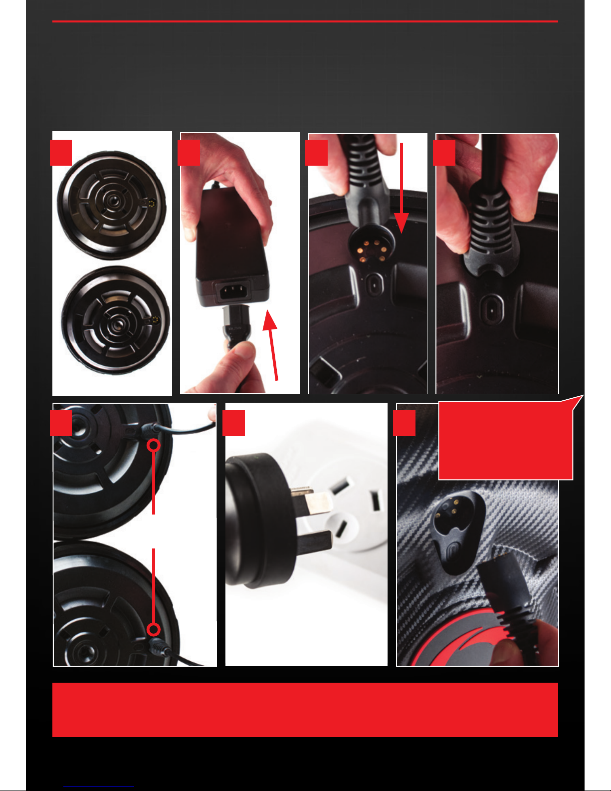
3.1 Remove Smart Wheels from packaging and place face down.
3.2 Remove the two charger power cables )(2 parts) and connect
to each other as shown below.
3.3 Now connect corresponding charging sockets to each wheel.
Ensure these cables are firmly connected to the wheels, and
charger power cables connected before connecting to the
power point in step 6.
1300 650 059 | concoursegolf.com
5
3.0
CHARGING INSTRUCTIONS
IMPORTANT: DO NOT CONNECT CHARGER TO POWER POINT UNTIL BOTH CHARGER POWER CABLES ARE
CONNECTED TO THE WHEELS .
User Instruction Manual | Version 3.0
1 2
ENSURE BOTH WHEELS
ARE CONNECTED
If you have purchased the
optional Travel Case and once
you are familiar with the charging
process you may connect
and charge the wheels whilst
remaining in the Travel Case.
3 4
5 6 7
Page 6
User Instruction Manual | Version 1.71300 650 059 | concoursegolf.com
6
1300 650 059 | concoursegolf.com
IMPORTANT: PLEASE ENSURE BOTH THE WHEELS AND REMOTE ARE FULLY CHARGED AND KEPT ON CHARGE AT ALL
TIMES BETWEEN ROUNDS OF GOLF. ONLY REMOVE THE CHARGER FROM THE WHEELS WHEN YOU ARE READY TO
PLAY. ALSO AVOID PARTIAL CHARGING WHICH MAY AFFECT LONG TERM BATTERY LIFE.
CHARGING
FULL CHARGE
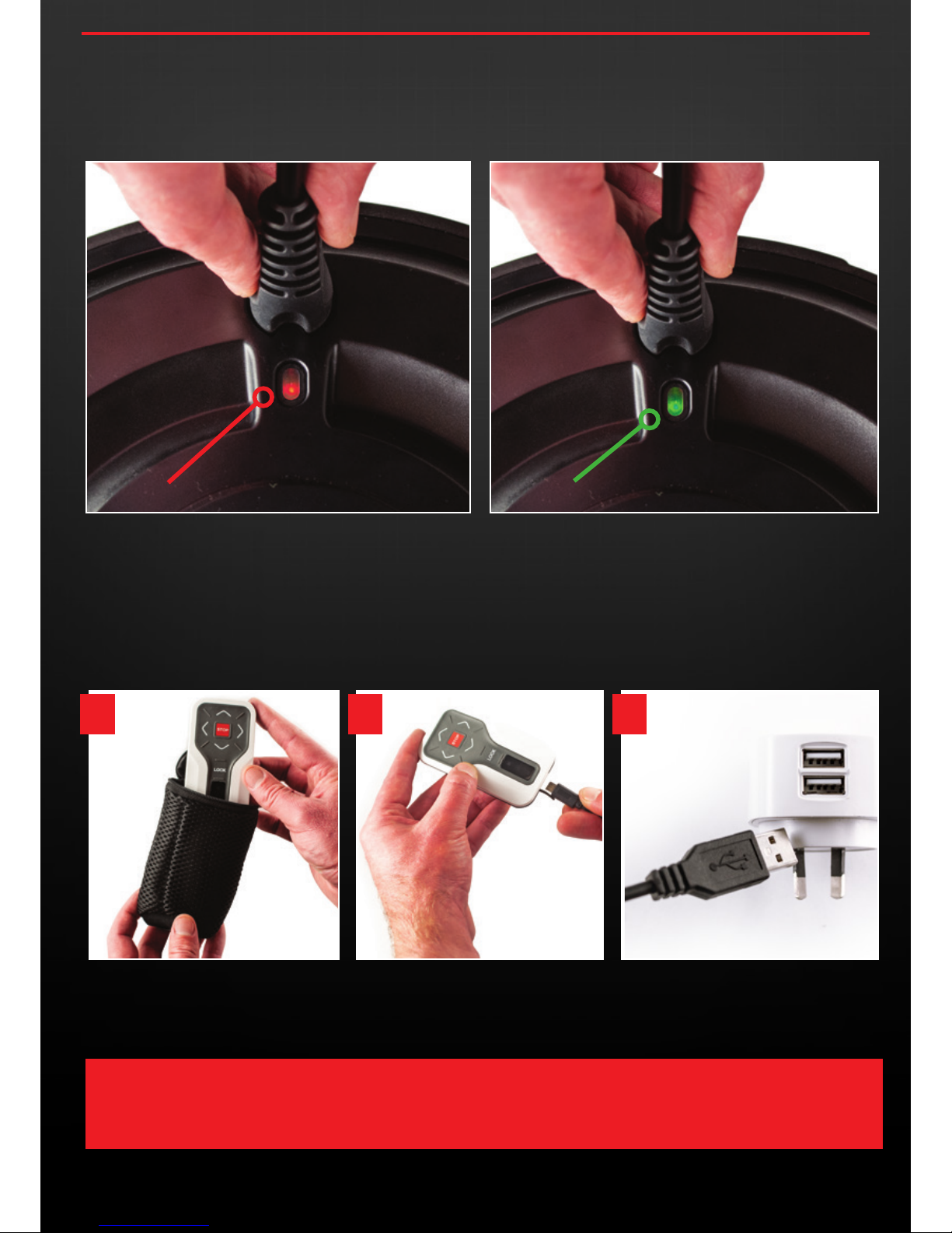
3.4 You may now connect the charging unit to a Power Point and
begin charging for the first time. You will notice an LED light just
below the wheels charging point that should appear RED when
charging begins, and then turn GREEN once the wheels are fully
charged.
3.5 Remove the remote control unit from it’s packaging and
connect the USB charging cable. Now connect the Remote USB
Charging Cable to a USB Charging Port .
Whilst this can be done via a computer’s USB, it is
recommended to use a USB charger that connects directly to
mains power for the most effective and quickest charge.
User Instruction Manual | Version 3.0
1 2 3
Page 7
1300 650 059 | concoursegolf.com
7
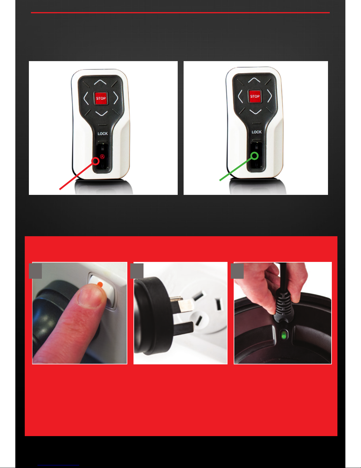
IMPORTANT : ONCE BOTH YOUR WHEELS ARE FULLY CHARGED AND A GREEN LED IS
SHOWING ON BOTH WHEELS, FIRST TURN OFF THE CHARGER AND THEN REMOVE THE
POWER LEAD FROM THE OUTLET BEFORE DISCONNECTING THE WHEELS.
FULL CHARGE
(LIGHT TURNS OFF)
CHARGING
3.7 Once both your Smart Wheels and remote are fully charged
please follow the disconnection instructions below very carefully.
3.6 When charging of the remote begins, you will notice the
middle light on the remote illuminate to Red indicating
charging is required or in process. Once the remote is
completely charged there will be no light showing.
CHARGER DISCONNECTION
User Instruction Manual | Version 3.0
1 2 3
Page 8
8
1300 650 059 | concoursegolf.com
4.0
CONNECTING THE SMART WHEELS TO YOUR CLICGEAR
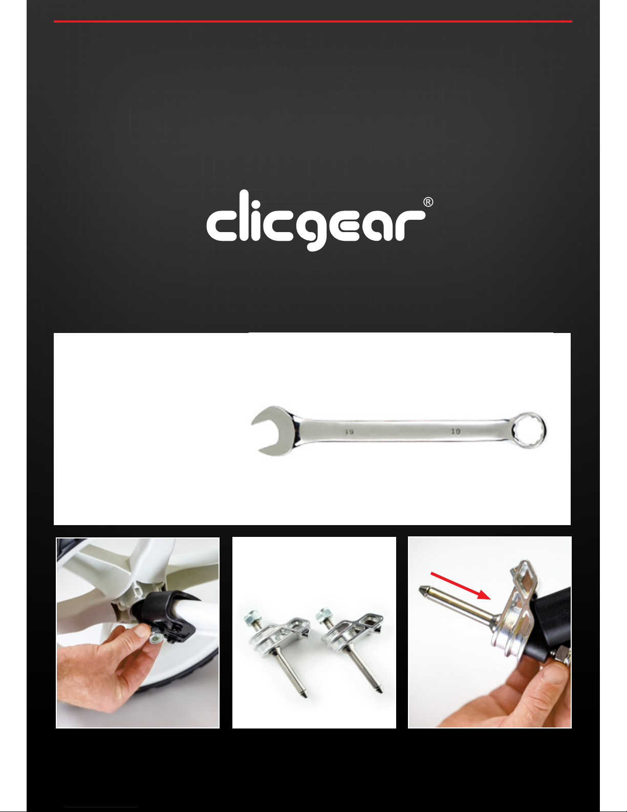
4.1 Position your buggy in a safe manner then remove the original
Clicgear buggy wheels by unscrewing the lock-nut. Please
ensure you use a 19mm Ring spanner to avoid damaging the
nut.
4.2 Position your buggy in a safe manor then remove the lock nut
on your original buggy wheel using a 19mm ring spanner and
then remove the Wheel.
4.3 Locate the 2 small metal Smart Wheel Axles – Left and Right
are the same and fit on either side. You will notice for Clicgear
buggies the axles are attached using a lock nut.
4.4 Connect both Smart Wheels axles to your existing push
buggy where you removed the original buggy wheels from as
indicated below.
MOST CLICGEAR MODELS
PUSH MODELS ONLY
19MM RING
SPANNER REQUIRED
User Instruction Manual | Version 3.0
Page 9
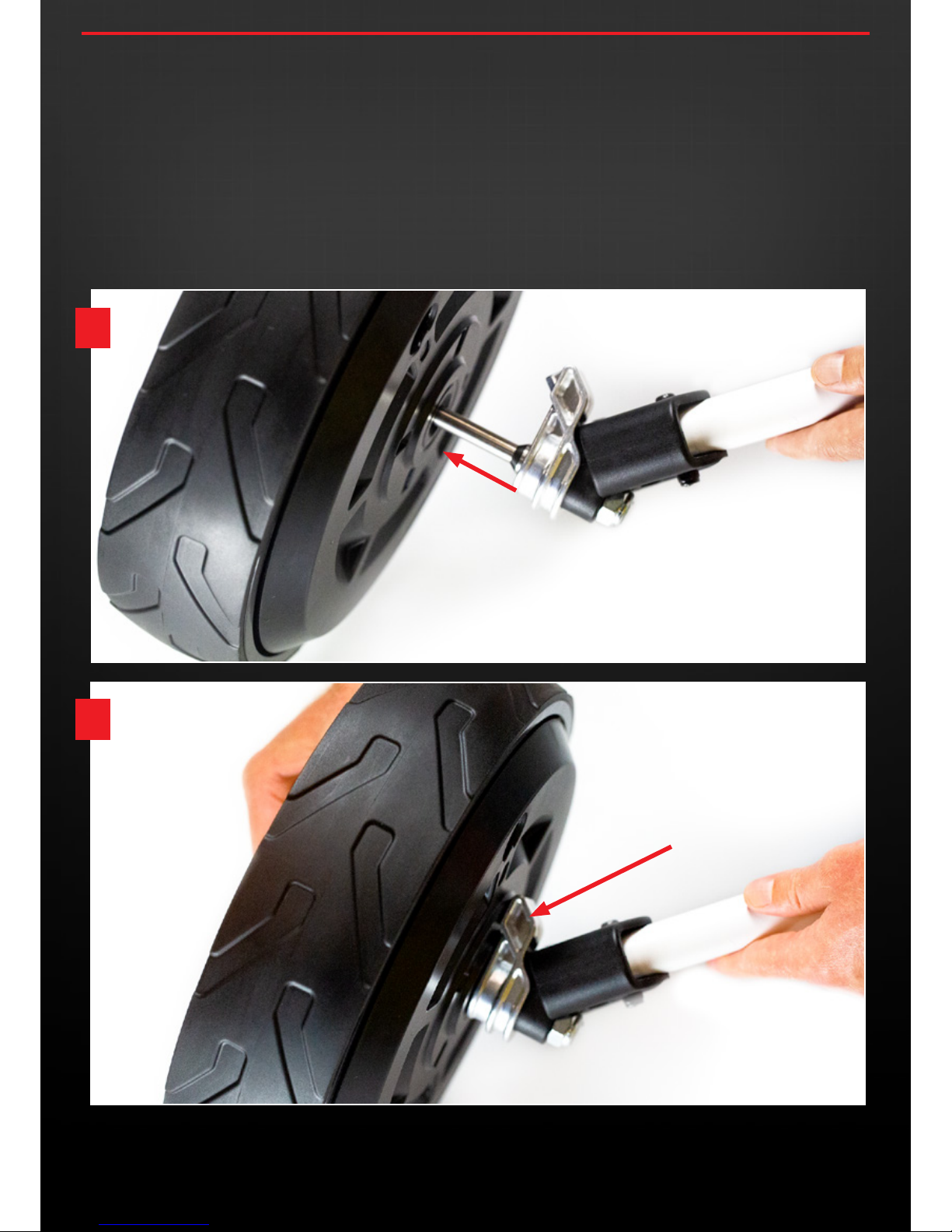
4.5 The Smart Wheels are labelled Left and Right.
Left and Right of the buggy is determined by standing behind
the buggy holding the handle as you would do during play.
Now pick up one wheel and guide it onto the Axle already
connected to your buggy. To avoid excess dirt clogging the
charging socket it is recomended to position the charging
socket at the highest point from the ground as you slide the
wheel into positon. Press the red button on the outside of the
wheel as you guide it onto the axle. Release the red button
when the wheel is in position.
4 .6 To ensure each Smart Wheels is securely locked in place you
may need to slightly rotate (up to ¼ turn) so the raised point
on outside of the axle neatly slots into the corresponding
indentation on the hub of the wheel.
This ensures the central hub of each Smart Wheel locks in place
and does not free-wheel.
Once both wheels are connected in the same manner they will
be able to drive the buggy.
2
1
1300 650 059 | concoursegolf.com
9
SECURELY LOCKED IN POSITION
User Instruction Manual | Version 3.0
Page 10
5.0
CONNECTING THE SMART WHEELS TO YOUR CBM3 BUGGY
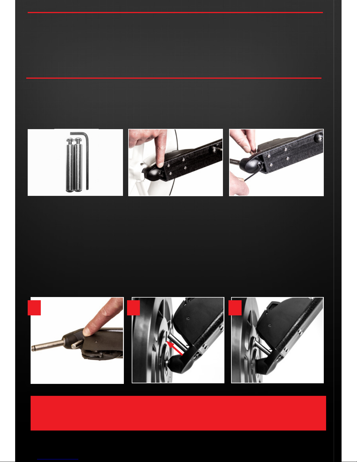
As an owner of the Concourse CBM3 Push Buggy you will not need to fit different axles (as opposed to other push buggy models).
The Smart Wheels will connect directly to the CBM3 axle, however, you do require locking pins to secure the central hub of the
Smart Wheels so the outer drives your buggy.
Before installing the CBM3 axle locking pins, please ensure you position your buggy in a safe and stable manner then remove the
two large free spinning wheels.
5.1 Enclosed you will find two locking pins and a 3mm allen key
as shown below.
5.2 You will notice a hole [also shown below] to thread the
locking pin screw through using the allen key.
5.3 Remove the original buggy wheels. Hold the locking pin,
then using the allen key thread the locking pin screw on
smoothly until it’s secure and tight. Repeat this process with
the opposite side of the CBM3 buggy.
5.4 The Smart Wheels are labelled Left and Right.
Left and Right of the buggy is determined by standing behind
the buggy holding the handle as you would during play.
Now pick up one wheel and guide it onto the Axle already
connected to your buggy. To avoid excess dirt clogging the
charging socket it is recomended to position the charging
socket at the highest point from the ground as you slide the
wheel into positon. Press the red button on the outside of the
wheel as you guide it onto the axle. Release the red button
when the wheel is in position.
5.5 To ensure each Smart Wheels is securely locked in place you
may need to slightly rotate (up to ¼ turn) so the raised point
on outside of the axle neatly slots into the corresponding
indentation on the hub of the wheel.
This ensures the central hub of each Smart Wheel locks in place
and does not free-wheel.
Once both wheels are connected in the same manner they will
be able to drive the buggy.
1300 650 059 | concoursegolf.com
10
1300 650 059 | concoursegolf.com User Instruction Manual | Version 3.0
1 2
LOCKED IN POSITION
3
PLEASE NOTE:
THE LOCKING PINS WILL SUIT EITHER SIDE OF THE BUGGY.
Page 11
1300 650 059 | concoursegolf.com
11
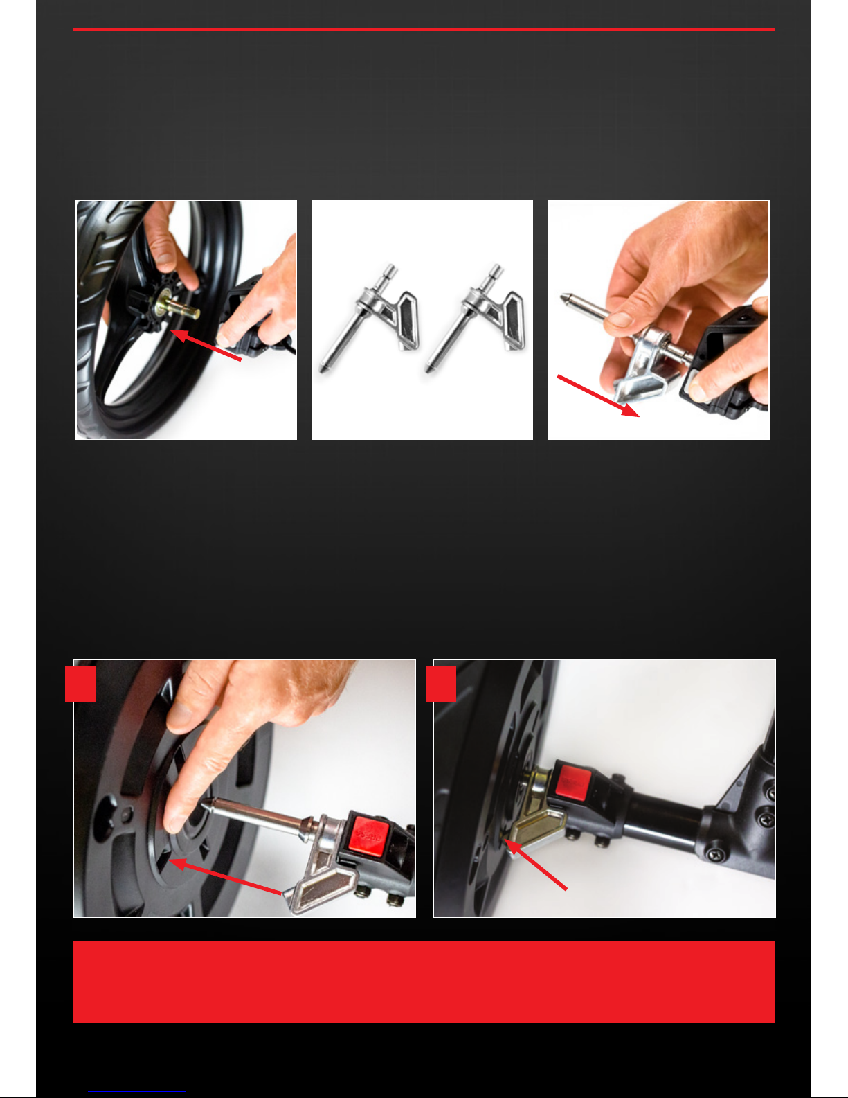
6.1 Position your buggy in a safe manner then remove the original
buggy wheels.
6.2 Locate the 2 small metal Smart Wheel Axles – Left and Right are
the same and fit on either side.
6.3 Connect both Smart Wheels axles to your existing push buggy
where you removed the original buggy wheels (as indicated
below).
Please ensure each firmly click into place, then pull on the axles
to test that they are secure.
6.4 The Smart Wheels are labelled Left and Right.
Left and Right of the buggy is determined by standing behind
the buggy holding the handle as you would during play.
Now pick up one wheel and guide it onto the Axle already
connected to your buggy. To avoid excess dirt clogging the
charging socket it is recomended to position the charging
socket at the highest point from the ground as you slide the
wheel into positon. Press the red button on the outside of the
wheel as you guide it onto the axle. Release the red button
when the wheel is in position.
6.5 To ensure each Smart Wheels is securely locked in place you
may need to slightly rotate (up to ¼ turn) so the raised point
on outside of the axle neatly slots into the corresponding
indentation on the hub of the wheel.
This ensures the central hub of each Smart Wheel locks in place
and does not free-wheel.
Once both wheels are connected in the same manner they will
be able to drive the buggy.
6.0
CONNECTING THE SMART WHEELS TO OTHER MODELS
1 2
SECURELY LOCKED IN POSITION
User Instruction Manual | Version 3.0
CAUTION:
• PLEASE ALWAYS ENSURE WHEN ATTACHING OR REMOVING WHEELS FROM YOUR BUGGY IT IS SECURELY
SUPPORTED/HELD-UP, TO AVOID RISK OF INJURY OR EQUIPMENT DAMAGE.
Page 12
12
1300 650 059 | concoursegolf.com
12
1300 650 059 | concoursegolf.com User Instruction Manual | Version 3.0
7.0
REMOVING YOUR SMART WHEELS
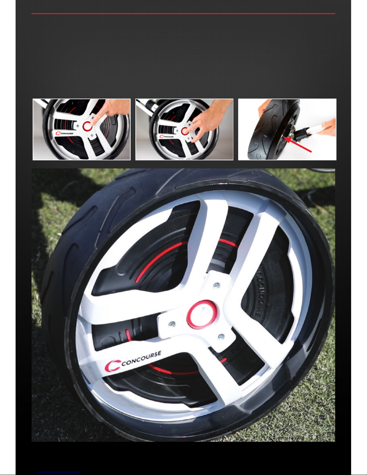
7.1 You can release each of the Smart Wheels by locating the
button in the middle of the outside facing side of the Smart
Wheel.
7.2 To completely remove the Smart Wheels from your buggy,
depress and hold down the button in the middle of the
outsideof the wheel and guide the wheel off it’s axle
completely.
NB: Please ensure when doing so that the buggy is safely
balanced and supported to avoid it toppling over.
Page 13
User Instruction Manual | Version 1.7
13
13
1300 650 059 | concoursegolf.com
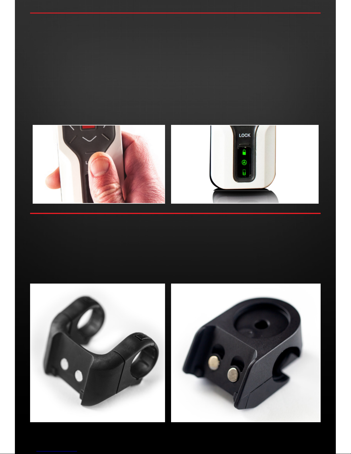
9.0
REMOTE CONTROL MOUNT
8.0
REMOTE CONTROL FUNCTION
8.1 Prior to using your remote control, ensure it has been fully
charged (refer to Section 3 for instruction).
8.2 To switch on the remote, press & hold the “LOCK” button
located in the middle of the remote control just above the LED
lights.
Once activated you will see the LED lights initially illuminating
blue and flashing before turning green. The blue flashing
indicates the remote control is ‘syncing’ with the wheels and
registering charge levels.
8.3 Once all 3 LED’s turn green, remove your finger from the lock
button and when there are no lights showing on the remote,
you are ready to operate the Smart Wheels by remote control.
8.4 If any one of the 3 lights appear red, it indicates either the
wheels are not charged sufficiently, the remote is not charged
sufficiently, or the remote control is locked. To charge either
the remote and or Smart Wheels, please refer to the Charging
Instructions in Section 3.
8.5 To unlock the remote control, simply press the “Lock” button
again and follow the procedure outlined in 7.2 .
9.1 To attach your remote control mount to your Buggy Handle use
the Allen key provided in the kit.
9.2 Fix the Mount on the centre of your push buggy handle so you
can reach the controls using either your left or right thumb.
9.3 Undo the mounting bracket, position the mount around the
handle and then finger tighten the screws so they thread cleanly
back into the mount.
9.4 Once positioned suitably, moderately tighten the mounting
screws so that the remote control mount is securely in position.
CBM3 MOUNT
User Instruction Manual | Version 3.0
Page 14
14
User Instruction Manual | Version 3.01300 650 059 | concoursegolf.com
14
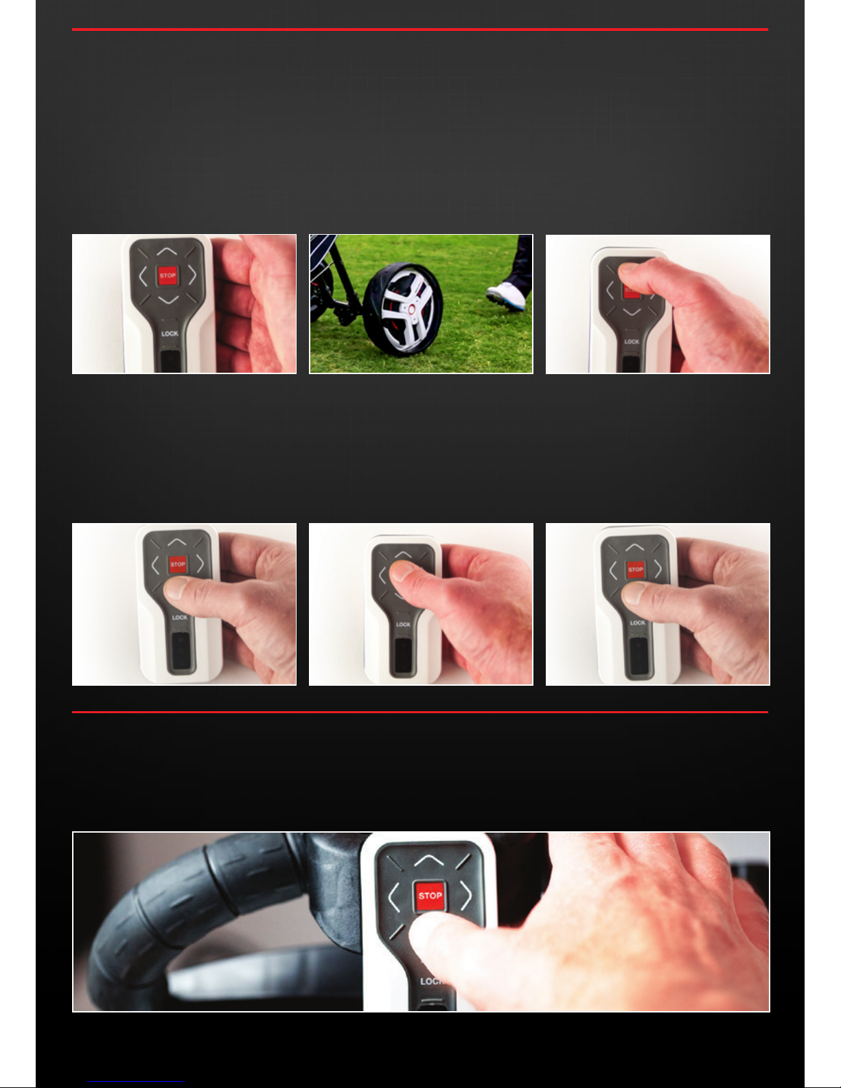
10.1 There are a total of 5 different forward moving speeds the
wheels can transition through to suit your comfortable walking
speed. From static position the Smart Wheels will always
commence in the lowest speed for safety purposes.
10.2 The Smart Wheels are also designed to wirelessly
communicate and maintain speed on varied terrain. To avoid
the buggy accidently tipping on hilly terrain it is recomended to
keep within your reach to reduce risk of accidental dammage.
10.3 FORWARD - Press the forward button to start the Smart Wheels
from stationery position, then to progressively accelerate
through each of the speeds by simply holding the FORWARD
arrow until you reach the desired speed.
10.4 DECELERATING – To decelerate the Smart Wheels press the
REVERSE arrow and hold down until you slow to the desired
speed or come to a complete stop.
10.5 STOP – To stop the Smart Wheels from any speed simply press
the red STOP button located in the middle of the control panel.
The wheels will come to a reasonably quick stop (Note: up to a
few metres if moving at the highest speed).
10.6 REVERSE – To drive the Smart Wheels in REVERSE press and
hold the REVERSE arrow to move your buggy the desired
distance.
Steering left and right by the remote when the remote is not sitting
in it’s cradle is correct, although when it is being operated with the
remote in it’s cradle left and right steering buttons are disabled and
power assisted manual steering occurs. ie: you steer the buggy by
lightly pulling left or right on the handle and the wheels will power
assist the change of direction (like power steeping on a car).
10.0
OPERATING
POWER ASSISTED MANUAL STEERING
FORWARD
DECELERATING STOP REVERSE
Page 15
15
1300 650 059 | concoursegolf.com
15
FOR TERMS & CONDITIONS VISIT OUR WEBSITE
12.0
WARRANTY & SERVICE
WARRANTY CLAIM PROCEDURE & SUPPORT
Contact Concourse Golf National Customer Service Team.
Email: [email protected]
Phone: Toll Free - 1300 650 059
If the fault is deemed a Warranty Claim by Concourse Golf and the Smart Wheels comply within the Concourse Warranty Conditions and
Exclusions, then all costs relating to repairs or replacements will be carried out free of charge.
We believe that Concourse quality is exceptional and we’re confident you’ll agree. In the unlikely event that your Concourse product
develops a problem, simply call 1300 650 059 and our National Customer Service Team will arrange either a repair or replacement with a
minimum of delay.
PRODUCT WARRANTY
The Warranty applies to the Smart Wheels by the serial number being located on the Instruction Manual and the delivery Carton provided
with the Smart Wheels at time of purchase. The Warranty is transferable to all owners of the Buggy and or Smart Wheels provided the
Buggy and or Smart Wheels are within the country of purchase during the Warranty period.
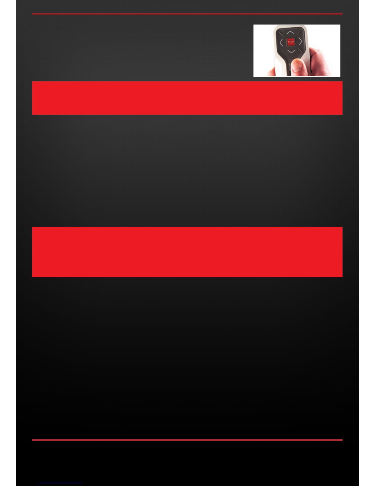
To activate the park brake you simply press the stop button twice in succession on the
remote control and the park brake is activated.
There is no need to switch off the park brake when you are ready to move, just simply press
forward or reverse on the remote and the park brake disengages automatically.
PARK BRAKE FUNCTION
PLEASE NOTE – ALTHOUGH THE PARK BRAKE IS DESIGNED TO ASSIST IN HOLDING THE BUGGY REASONABLY STABLE
WHEN UNATTENDED, IT IS HIGHLY ADVISED THAT YOU ENSURE THE BUGGY IS PARKED IN A SAFE MANOR / POSITION
AND IT CANNOT RUN AWAY AND BECOME DAMAGED, PARTICULARLY AROUND WATER HAZARDS.
User Instruction Manual | Version 3.0
CAUTION: DO NOT ATTEMPT TO REPLACE BATTERY DUE TO RISK OF EXPLOSION. FOR BATTERY REPLACEMENT OR
SERVICE, PLEASE RETURN YOUR SMART WHEELS TO CONCOURSE GOLF.
FOR BATTERY DISPOSAL, PLEASE PRESENT THE WHEELS AND REMOTE AT AN AUTHORISED BATTERY DISPOSAL CENTRE
NEAR YOU, OR RETURN THEM TO CONCOURSE GOLF.
PLEASE ALSO ENSURE THE REMOTE IS ALWAYS CHARGED BY A COMPLIANT USB CHARGER (LIMITED POWER SOURCE
COMPLIANT WITH CLAUSE 2.5 OF EN 609050-1:2006).
For safety purposes and to avoid your buggy ‘running away’
from you, the remote range has been designed to allow for
operation up to 50m.
Beyond 50m the Smart Wheels will automatically come to a
stop and a red and blue light will appear on the remote. Once
you return within range, the remote lights will turn green. The
Smart Wheels will then be ready to operate again, only once
you press the desired directional arrow to begin driving them.
Note: The Smart Wheels are also designed to automatically
stop if the buggy tips completely for safety and protection
purposes, however, it is stongly recomended to keep the
buggy within reach on undulating terrain to avoid the buggy
accidently tipping and causing excess strain on components.
In the event your Smart Wheels discharge fully the wheels can
easily be converted to a free wheeling function. By pressing
the button in the middle of the wheels and partially sliding the
wheel out you will feel it click into “1st Position”. Once it clicks
into this position you will notice the raised point on the outside
of the axle is clear of the indentation of the wheel. This enables
the wheels to rotate freely and your buggy to be pushed
manually.
11.0
IMPORTANT INFORMATION
Page 16
1300 650 059 | concoursegolf.com
User Instruction Manual | Version 1.7
Concourse Golf Pty. Ltd. has made every attempt to ensure the accuracy and reliability of information stated in this user manual to be correct at the time of printing, however,
details are subject to change without notice.
 Loading...