

CONCH HM-730S Installation Instructions Manual
HM-700 Series Human-Machine Interface
HM-730S
Installation Instructions
V1.02 2013-08-05
1. Installation Instructions
HMI is the CPI information products, may result in the use of RF interference
or electromagnetic waves are generated, may affect other appliances, the user
must ensure compliance with the following installation instructions to ensure
the correct use of safety.
1.1. Safety Precautions
You should pay attention to the following safety precautions when installation,
wiring, operation, maintenance and inspection.
1.1.1. Installation Notes
1. Following the specified instruction to install the HMI, or it may result in
equipment damage.
2. Prohibited to let the HMI to exposure in moisture, corrosive gases,
flammable gases and other substances, or it may result in electric shock or
fire.
3. Serial communication cable and network cable and power cable should be
separated, and must be used to mask the cable, otherwise it may cause
unpredictable problems.
4. Attention! When drilling or work with HMI, you should not let the cut wires
or filler and other impurities fall into the HMI internal.
1.1.2. Power Wiring
1. The input power of HMI using a DC power supply, voltage range of 24 ±
20% VDC, too much or too less will be serious damage to HMI. Regularly
check the power supply of DC power source to see if it is stable or not.
2. To avoid electric shock, before connecting to the communications cable or
download cable, please cut off the HMI power.
3. DC power supply must be properly isolated from the main AC power.
4. Do not let the input circuit of HMI and inductive load (solenoid or
electromagnetic switch), inverter or driver to share the power supply.
1.1.3. Power wiring method
1. Please remove the quick connector from HMI body when wiring.
2. Only one cable can be inserted into the cable socket of quick connector.
3. 24VDC' anode connect to the terminal marked as a "+", and 24VDC
cathode connect to the terminal marked as a "-".
4. When error compulsorily pulls out the wire, you should re-check the
connection cable and start.
5. The proposed wiring material are as follows:
Type
Wire Gauge (AWG)
Stripped Length
Torque
Multi-core wire
22~16
7~8 mm
4.5 lb-inch
Single-core wire
22~16
7~8 mm
4.5 lb-inch
1.1.4. FG grounding requirements
1. Please use at least 2mm 2(AWG14) as a grounding conductor, grounding
impedance must be less than 100Ω (class3).
2. Please use the independent grounding pole, should not connect to the
grounding conductor of power circuit.
3. Ground conductors should be as short and as large in size as possible.
The conductors must always be large enough to carry the maximum short
circuit current of the path being considered. Ground conductors should be
connected to a tree from a central star earth ground point. This ensures
that no ground conductor carries current from any other branch.
1
2
4. When FG terminal is connected, please check if the wire is grounded
properly. Because improper grounding may result in communication error,
electric shock or fire.
1.1.5. Communication cable wiring Notes
1. Comply with communication wiring specification for wiring.
2. Restrict cable length to less than 500’(150m) for RS485/422 devices and
50’(15m) for RS232 devices to avoid communication problems.
3. Proper grounding circuit to avoid bad communication quality.
4. Shielded cable must be used for long lengths or cables run in an
electrically noisy environment.
5. When wiring, should be away from AC power cable and high energy and
rapidly switching DC wiring cable.
1.1.6. Operation Notes
1. HMI should meet the editing software to plan the screen. Un-planned HMI
may not be able start the application, or result in abnormal operation.
2. Shouldn't change the wiring when the power is turned on, or it may result
the electric shock or human injure.
3. Do not use a sharp object to touch the panel, or it may cause the panel
sunken, and thus cannot make HMI operate normally.
4. The backup data of this product using the rechargeable lithium battery to
supply the electric, therefore, do not let the product with power off for a
long time (more than 6 months) to cause the low battery and let the kept
data missing (system parameter, recipe, resume...)
1.1.7. Maintenance Checks
1. Prohibiting touch HMI internal, otherwise it may cause electric shock.
2. Prohibiting dismantle the operation panel when power is on, otherwise, it
may cause electric shock.
3. When the power is off for 3 minutes, should not touch the terminal block,
otherwise, the residual voltage may cause electric shock.
4. The vent of HMI should not obstructed, otherwise, it may easily cause a
malfunction.
1.2. Installation and storage environmental conditions
The product must be kept in the shipping carton before installation. In order to
retain the warranty coverage, the HMI should be stored properly when it is not
to be used for an extended period of time. Some storage suggestions are::
1. The storage location should be dry with no dust, should've better with
correctly packaged and placed on a solid shelf surface.
2. Store within an ambient temperature range of -20°C~+60°C (-4°F~140°F).
3. Storage location' ambient relative humidity must be within the range of
10% to 90% without condensation.
4. Do not store in the environment of corrosive gases and liquids.
5. The suitable installation environm ent : No heat-radiating elements, no
water droplets, no vapor, no dust and oily dust' place; non-corrosive,
flammable gases, liquids spaces; no airborne dust or metallic particles of
places; sturdy no vibration、no electromagnetic noise interference' places.
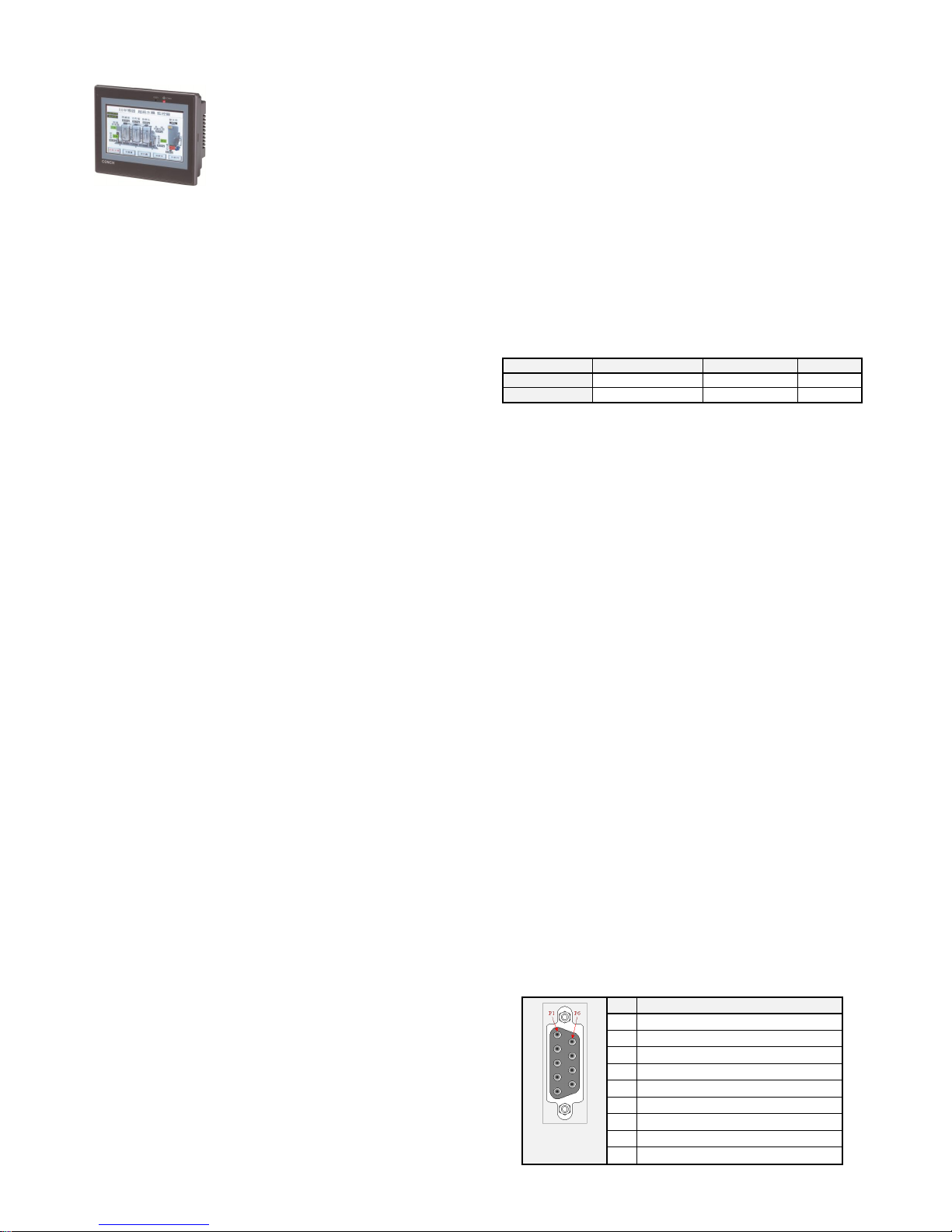
2. Serial port pin definitions
COM1 – ( Support RS232 / RS485 )
D type / 9P
Female socket
Pin
Pin Definitions
1
RS485+
2
RS232 RXD
3
RS232 TXD
4
Terminal resistor for RS485+
5
Signal Ground
6
RS485-
7
RS232 RTS
8
RS232 CTS
9
+5VDC Output ( Maximum 100mA )
3
4
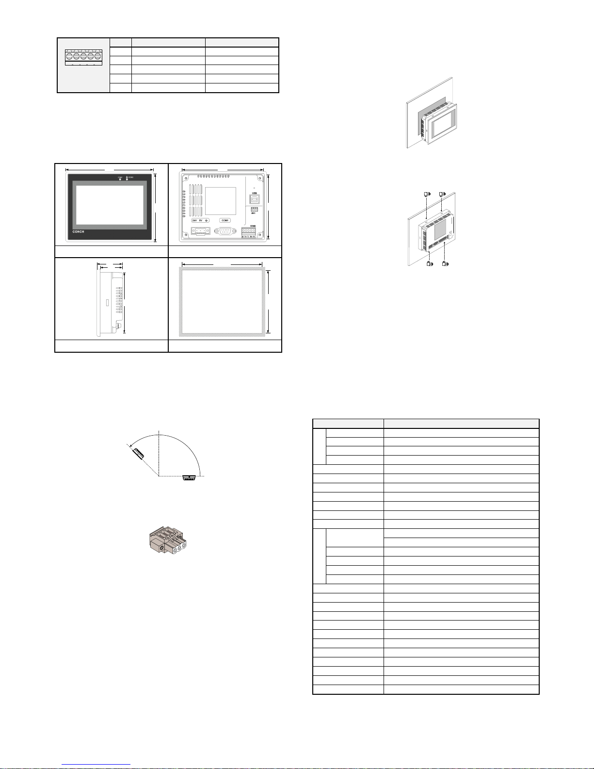
COM2/COM3 – ( Support RS485 / RS422 )
G T+ T- R+ R-
5P terminals
Pin
COM2 Pin Definitions
COM3 Pin Definitions
G
Signal Ground
T+
RS422 TX+ / RS485+
T-
RS422 TX- / RS485-
R+
RS422 RX+
RS485+
R-
RS422 RX-
RS485-
△
!
COM2 can provide 2 kinds of RS485 and RS422 communication
interfaces. COM3 will be enabled when it is in RS485 mode.
3. Mounting
The dimensions of HM -730 - (unit: mm)
Front View
Rear View
Side View
Cutout dimensions
Installation sequence -
1. On a fixed panel, follow the recommendations of mounting diagram to
cutting an area, to install HMI on this panel. As below diagram: (please
make sure to install the waterproof ring before HMI installation) .
2. Make sure the fixed piece screw is installed into the HMI fixed holes, and
then the beneath hooked the front cover, screw head is withstand the
insides of control box. As below diagram:
3. Pl eas e lo ck tig ht wit h 0 .5 N • m tor que an d do not exc eed th is fo rce ,
otherwise, it may damage t he pla sti c sh ell. (to rqu e 0. 5N • m = 4.4 3lb -inch)
5
6
The Installation angle should be between 0 ° ~ 135 °. As below diagram:
90°
135°
0°
Power wiring steps -
1. First, unplug the power terminals, and then use a flat-blade screwdriver to
loosen the screw.
2. Strip 24VDC power cord ( stripping length 7~8 mm ), according to the
polarity insert the power terminal to the corresponding position.
3. Using a flat-blade screwdriver to lock tight the power terminal screw.
4. At last, insert the power terminal into HMI power supply end.
4. Specifications:
Item No.
HM-730 S
Display
Type(65K colors)
4.3” TF T LC D ( 655 36 colors)
Backlight module
LED backlight (Average life 30,000 hours)
Resoultion (pixels)
480 x 272 pixels
Display Size
95.00mm(W) x 53.8mm(H)
Operation System
Embedded R eal Time OS
CPU
32-bit RISC 400MHz
SDRAM
64MB DDR2 RAM
Program memory RO M
45MB NAND Flash Memory
Backup mem ory SRAM
256KB (Maxi. extended to IMB) / 3V lithium battery
RTC
Built-in
Function Key
/
Interface
Serial Port
COM1-( RS232 / RS485 )
COM2/CO M3- ( RS485 / RS422 )
USB Device
USB2.0 Client x 1 (Project pr ogram downloading)
USB Host
/
Ethernet
/
SD Card
/
Input Voltage
24±20% VD C
Power Consumption
Maxi.8W @24VDC
Store Ambient Temp.
-20°C ~ +60°C ( -4°F ~ 140°F )
Operatoin Temp.
0°C ~ +50°C ( 32°F ~ 122°F )
Relative Humidity
10 ~ 90% RH non-condensing
Cooling Method
Natural air circulation
Panel Prot ection Level
IP65, D ust-proof, Drop-proof design (O-ring waterproof)
Shell Material
Industrial Plastic
Vibration resis tance
10~50Hz (x、 y、 z each direction 2G 30 minutes)
Dimensions
128(W) x 102(H) x 39(D) mm
Panel Cutout
119.0±0.5(W) x 93.0±0.5(H) mm
Weight
Approx. 230g
※ Model type and specification are subjected to chan ge without notification
7
8
119.0±0.5
93.0±0.5
92.0
39.0
34.0
118.0
92.0
128.0
102.0
 Loading...