

Page 1

Issue V1.0
Date 01-03-2017
VHSDIR-812EXT-IP3M
External IR Network High Speed Dome
User Manual
Page 2

Page 3
External IR Network High Speed Dome
User Manual
Precautions
V1.0 (01-03-2017)
i
Precautions
Precautions
Please be sure to fully understand this document before using this device, and
strictly observe all rules in this document when using this device. Please also be sure
installation of this device abides by local surveillance rules and regulations. Failure
to correctly use electrical products may cause fire and severe injuries. To prevent
accidents, carefully review the following information.
Symbols
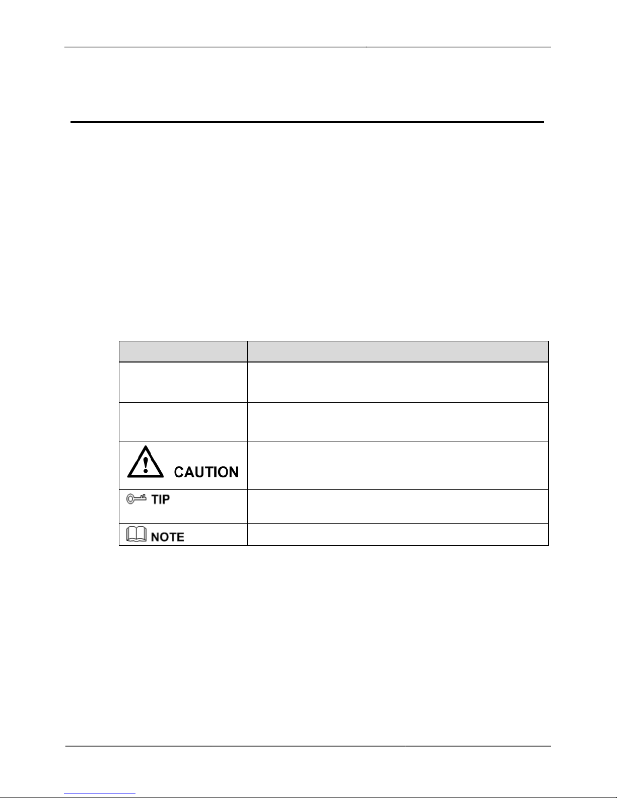
This document may contain the following symbols whose meanings are described
accordingly.
Symbol
Description
Alerts you to fatal dangers which, if not avoided, may
cause death or severe injuries.
Alerts you to moderate dangers which, if not avoided,
may cause minor or moderate injuries.
Alerts you to other risks. Neglecting these advisories may
cause device damage, data loss, deteriorated device
performance, or unpredictable operation.
Provides a tip that may help you resolve problems or save
time.
Provides additional information for reference.
To prevent electric shock or other danger, keep power plugs dry and clean.
!
Strictly observe installation requirements when installing the device. The
manufacturer shall not be held responsible for device damage caused by users' nonconformance to these requirements.
Page 4
External IR Network High Speed Dome
ii
V1.0 (01-03/2017)
Precautions User Manual
!
Strictly conform to local electrical safety standards and use power adapters that are
marked with the relevant LPS standard when installing and using this device.
Otherwise, this device may be damaged.
!
Only use accessories delivered with this device. The voltage must meet input
voltage requirements for this device.
!
If this device is installed in places with unsteady voltage, ground this device to
discharge high energy such as electrical surges to prevent the power supply from
burning out.
!
When this device is in use, ensure that no water or any other liquid flows into the
device. If water or liquid unexpectedly flows into the device, immediately power
off the device and disconnect all cables (such as power cables and network cables)
from this device.
!
Do not focus strong light (such as lighted bulbs or sunlight) on this device.
Otherwise, the service life of the image sensor may be shortened.
!
If this device is installed in places where thunderstorms and lightning frequently
occur, ground the device nearby to discharge high energy such as lightning strikes
to prevent device damage.
!
Avoid heavy loads, intensive shaking, and soaking to prevent damage during
transportation and storage. The warranty does not cover any device damage that is
caused during secondary packaging and transportation after the original packaging
is opened.
!
Protect this device from drops and intensive strikes, keep the device away from
magnetic field interference, and do not install the device in places with vibrating
surfaces or shocks.
!
Clean the device with a soft, dry cloth. For stubborn dirt, dip the cloth into
slightly neutral cleanser, gently wipe the dirt with the cloth, and then dry the
device.
!
Do not jam the ventilation opening. Follow the installation instructions provided in
this document when installing the device.
!
Keep the device away from heat sources such as radiators, electric heaters, or other
heating equipment.
!
Keep the device away from moist, dusty, extremely hot or cold places, or places
with strong electric radiation.
!
If the device is installed outdoors, take insect- and moisture-proof measures to
avoid circuit board corrosion that can affect monitoring.
!
Remove the power plug if the device is idle for an extended period.
!
Before unpacking, check whether the fragile sticker is damaged. If the fragile
sticker is damaged, contact customer services or sales personnel. The manufacturer
shall not be held responsible for any artificial damage to the fragile sticker.
Page 5

External IR Network High Speed Dome
User Manual
Precautions
V1.0 (01-03-2017)
iii
Special Announcement
All complete products sold by the manufacturer are delivered along with name
plates, operation instructions, and accessories after strict inspection. The
manufacturer shall not be held responsible for counterfeit products.
This manual may contain misprints, inaccurate technological information, or product
function and operation descriptions that are slightly inconsistent with the
actual product. The manufacturer will regularly update this manual per product
function improvements/changes and regularly update the software and hardware
described in this manual. Updated information may be added to new versions of this
manual without prior notice.
This manual is only for reference and does not ensure that the information is totally
consistent with the actual product. For consistency, please refer to the actual
product.
Page 6

External IR Network High Speed Dome
iv
V1.0 (01-03/2017)
Contents User Manual
Contents
Precautions ..................................................................................................................... i
1
Overview .................................................................................................................... 1
1.1 Hardware connection ........................................................................................................ 1
1.2 Features ............................................................................................................................. 3
2
Device Dimensions ................................................................................................... 4
3
Device Installation .................................................................................................... 5
3.1 Installation Preparation ..................................................................................................... 5
3.2 Installing a Dome Camera ................................................................................................ 5
3.2.1 Installation Modes ................................................................................................ 5
3.2.2 Wall-Mounted Installation ................................................................................... 6
3.2.3 Suspension Installation ......................................................................................... 8
3.2.4 Celling-Mounted Installation ............................................................................... 9
4
Quick Configuration .............................................................................................. 11
4.1 Login and Logout ........................................................................................................... 11
4.2 Browsing Video ...................................................................................................................... 11
4.2.1 Download the right control in the Internet Explorer .......................................... 13
4.2.2 In the Google, Firefox, or Safari browsers watch real-time video ..................... 13
4.3 Setting Local Network Parameters ................................................................................. 14
5
Technical Specifications ........................................................................................ 16
6
Troubleshooting ...................................................................................................... 20
A Lightning Proof and Surge Signal Proof ........................................................... 21
B Hazardous Substance Declaration ...................................................................... 22
Page 7

IR Network High Speed Dome
User Manual
1 Overview
V1.0 (01-03-2017)
1
1 Overview
1.1 Hardware Connection
Figure 1-1 shows the appearance of the External IR Network High
Speed Dome.
Figure 1-1 External IR Network High Speed Dome
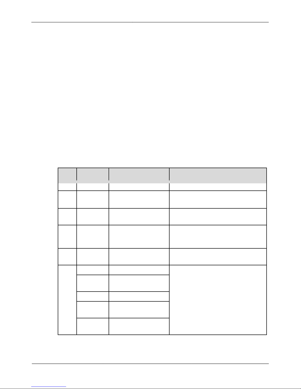
Figure 1-2 & Figure 1-3 show the multi-head cable used by the dome camera. Table 1- 1
describes each connection of the multi-head cable.
Figure 1-2 Multi-head cable
Page 8
IR Network High Speed Dome
2
V1.0 (01-03/2017)
1 Overview User Manual
Figure 1-3 Multi-head cable (optional)
Table 1-1 Hardware port connection
No.
Color
Function
Description
1
N/A
Network port
Connects a standard Ethernet cable.
2
N/A
DC 12V power supply
wire
Supplies power to the device.
3
Yellow/
Green
Grounding wire
N/A
4
White
taped core
Audio input
Receives analogue audio signals
from devices such as a
microphone.
5
Red taped
core
Audio output
Connects to an external active audio
device such as a speaker.
6
Purple
Alarm input channel 1
Two channels of switching-value
alarm input and one channel of
switching-value alarm output.
Grey
Alarm input channel
common terminal
Yellow
Alarm input channel 2
Orange
Alarm output channel
common terminal
White
Alarm output channel
1
Page 9

IR Network High Speed Dome
User Manual
1 Overview
V1.0 (01-03-2017)
3
1.2 Features
Network Features
!
Supports the complete TCP/IP protocol suite.
!
Supports video, audio, and alarm data.
!
Provides a built-in web browser and supports access using Microsoft Internet
Explorer.
!
Supports network data transmission and remote access.
!
Supports Point-to-Point Protocol over Ethernet (PPPoE), Dynamic Host
Configuration Protocol (DHCP), and Dynamic Domain Name System (DDNS).
!
Supports remote upgrade and maintenance.
Image Processing Features
!
Supports dual streams. Encoding parameters for the main stream and sub
stream can be configured separately.
!
Supports dynamic stream parameters based on different image quality requirements.
!
Supports independent hardware compression, constant bit rate (CBR), and Variable
bit rate (VBR). Videos can be compressed using the Motion Joint Photographic
Experts Group (MJPEG) or H.264 standard. The frame rate and bit rate can be
configured.
I/O Features
!
Support bidirectional intercom and unidirectional broadcast.
!
Provides a 10/100 Mbit/s self-adaptive Ethernet port.
Other Features
!
Supports the heartbeat function that allows the management host to learn the
running status of the IP camera in real time.
!
Support alarm input and output, motion detection alarm, and alarm linkage function.
!
Supports level-based user rights management.
Page 10
IR Network High Speed Dome
4
V1.0 (01-03/2017)
2 Device Dimensions User Manual
2 Device Dimensions
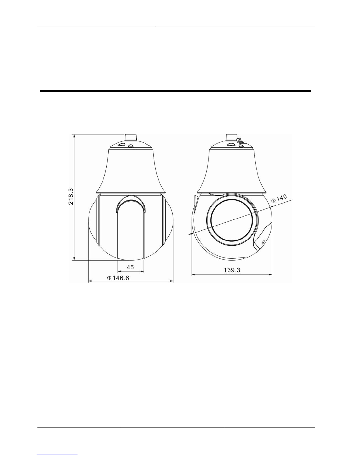
Figure 2-1 shows the camera dimensions.
Figure 2-1 Dimensions (unit: mm)
Page 11
V1.0 (01-03-2017)
5
IR Network High Speed Dome
User Manual
3 Device Installation
3 Device Installation
3.1 Installation Preparation
When installing the camera, you may require the following tools and accessories listed
in Table 3-1. You need to prepare only listed tools as other accessories are delivered
with the camera.
Table 3-1 Installation tools
Tool
Appearance
Cross screwdriver (not included)
Claw hammer (not included)
Impact drill (not included)
Level (not included)
3.2 Installing the Dome Camera
3.2.1 Installation Modes
The dome camera supports wall-mounted, pendant installation and ceiling-mounted
modes.
Preparation
!
Open the package of the camera, carefully take out the camera and the accessories.
Page 12
6
V1.0 (01-03/2017)
IR Network High Speed Dome
User Manual
3 Device Installation
!
Open the dome cover with a screwdriver where the SD card installs on the bottom
of the dome, remove the shake-proof metal block, and then re-tighten the cover .
!
Prepare the bracket before installing the camera.
3.2.2 Wall-Mounted Installation
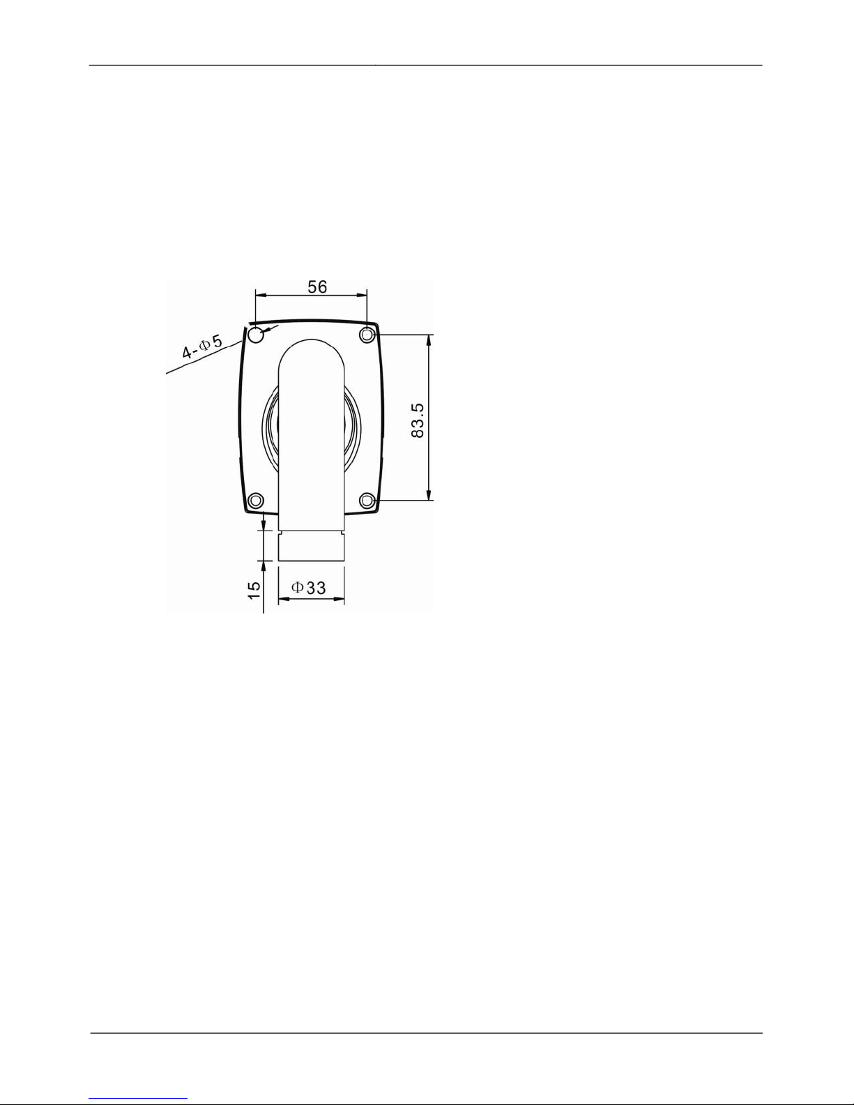
Step 1 Please make the mark based on bracket size before drilling holes into the wall. Drill
four φ8 holes over 60 mm depth. The bracket installation size is shown in Figure 3-1.
Figure 3-1 Bracket installation size
Step 2 Insert four expansion bolts into the holes.
Step 3 Thread all the cables through the wall bracket, as shown in the Figure 3-2.
Page 13

V1.0 (01-03-2017)
7
IR Network High Speed Dome
User Manual
3 Device Installation
Figure 3-2 Thread all cables through the wall bracket
Step 4 Attach the PTZ camera to the wall bracket and fit it into the connector. Then tighten the
three screws to fix the connector and camera, shown in the Figure 3-3.
Figure 3-3 Fix the bracket connector and PTZ camera together
Step 5 Mount the PTZ dome camera to the wall, tighten the four screws on the bracket
completely.
----End
Page 14

8
V1.0 (01-03/2017)
IR Network High Speed Dome
User Manual
3 Device Installation
3.2.3 Pendant Installation
Step 1 Make marks based on suspension bracket size for drilling the hole. Drill four φ8 holes
over 60 mm depth. The bracket installation size is shown in Figure 3-4.
Figure 3-4 Bracket installation size
Step 2 Insert the expansion bolts into the holes.
Step 3 Thread all cables through the cable hole on the side of the suspension bracket, as
shown in the Figure 3-5.
Figure 3-5 Thread the cables through the cable hole on the bracket
Page 15
V1.0 (01-03-2017)
9
IR Network High Speed Dome
User Manual
3 Device Installation
Step 4 Attach the PTZ camera to the suspension bracket and fit it into the connector. Then
tighten the four screws fixing the PTZ dome and bracket, shown in the Figure 3-6.
Figure 3-6 Fix the suspension bracket and PTZ dome together
Step 5 Mount the PTZ dome camera to the mounting surface and tighten the four
screws on the bracket completely.
3.2.4 Ceiling-Mounted Installation
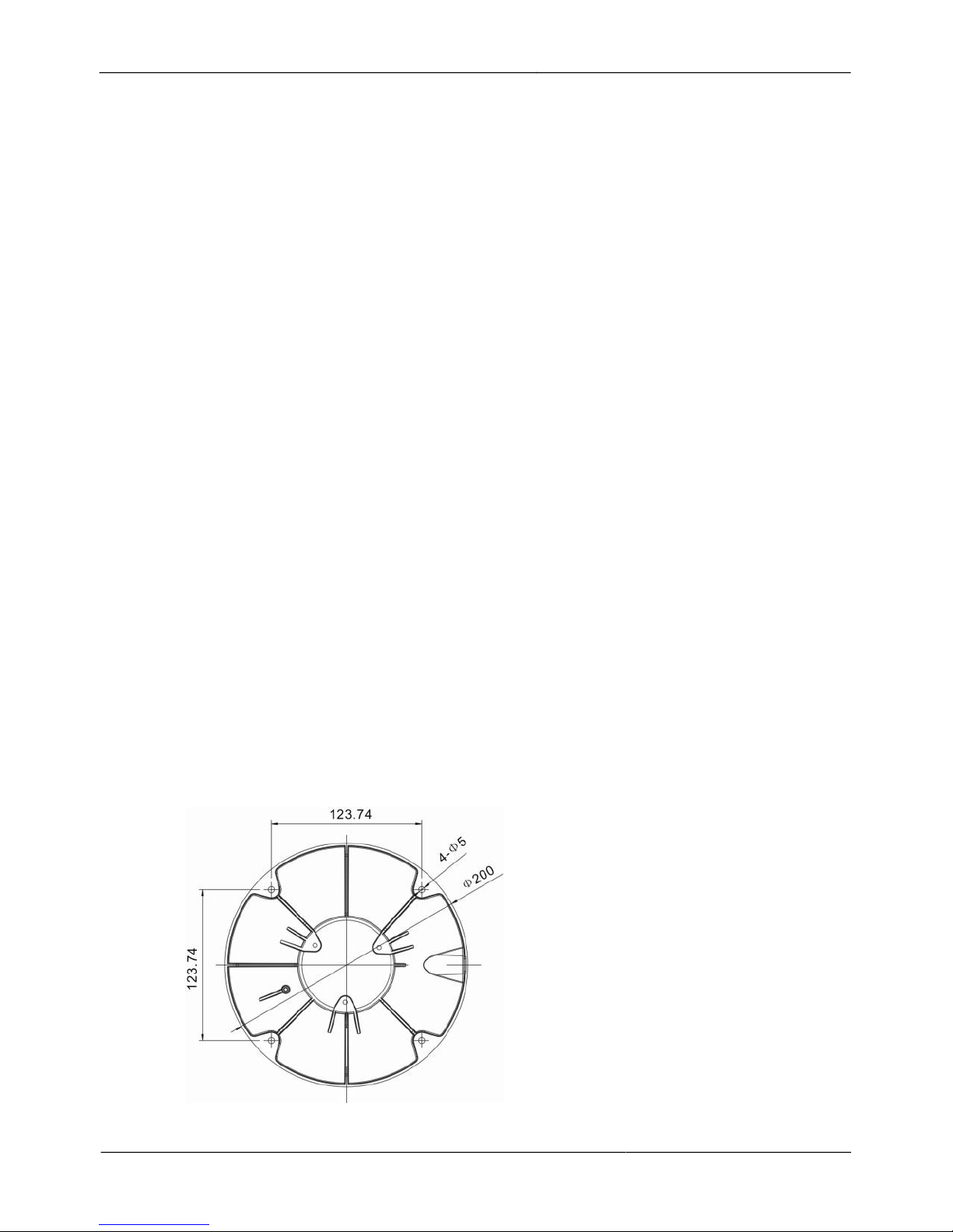
Step 1 Mark based on ceiling bracket size before drilling holes into the ceiling. Drill four φ8
holes over 60 mm depth. The bracket installation size is shown in Figure 3-7.
Figure 3-7 Bracket installation size
Page 16

10
V1.0 (01-03/2017)
IR Network High Speed Dome
User Manual
3 Device Installation
Step 2 Insert the expansion bolts into the holes.
Step 3 Thread all cables through the cable hole on the side of the celling bracket, as shown in
the Figure 3-8.
Figure 3-8 Thread the cables through the cable hole on the bracket
Step 4 Attach the PTZ camera to the celling bracket and fit it into the connector. Then tighten
the four screws fixing the PTZ dome and bracket, shown in the Figure 3-9.
Figure 3-9 Fix the celling bracket and PTZ dome together
Step 5 Mount the PTZ dome camera to the celling and tighten the four screws on the
bracket completely.
----End
Page 17
V1.0 (01-03-2017)
11
IR Network High Speed Dome
User Manual
4 Quick Configuration
4 Quick Configuration
4.1 Login and Logout
You must use Internet Explorer 6 or a later version to access the web management
system; otherwise, some functions may be unavailable.
Login to the camera
Step 1 Open the Internet Explorer, enter the IP address of IP camera (default value:
192.168.0.120) in the address box, and press Enter. The login page is displayed.
Step 2 Input the User name and password.
!
The default name is admin. The default password is admin. Change the password when
you log in the system for the first time to ensure system security.
!
Depending on the camera firmware version, you may be asked if you wish to enable
Enhanced Security. If so, you must then create a new user name and complex password
upon initial log-in.
!
You can change the system display language on the login page.
Step 3 Click Login.
The main page is displayed.
----End
Logout
To logout of the system, click Sign out in the upper right corner of the main page, the
login page is displayed after you log out of the system.
4.2 Browsing Video
Users can browse the real-time video in the web management system.
Preparation
To ensure the real-time video can be play properly, you must perform the following
operation when you log in to the web viewer for the first time:
Page 18

12
V1.0 (01-03/2017)
IR Network High Speed Dome
User Manual
4 Quick Configuration
1.
Open Internet Explorer. Choose Tools > Internet Options > Security > Trusted
sites > Sites.
In the display dialog box, click Add, as shown in Figure 4-1.
Figure 4-1 Adding a trusted site
2.
In Internet Explorer, choose Tools > Internet Options > Security > Custom level,
and set Download unsigned ActiveX control and initialize and script ActiveX
controls not marked as safe for scripting under ActiveX controls and plug-ins
to Enable, as shown in Figure 4-2.
Page 19

V1.0 (01-03-2017)
13
IR Network High Speed Dome
User Manual
4 Quick Configuration
Figure 4-2 Configuring ActiveX control and plug-ins
3.
Download and install the player control as prompted.
The login page is displayed when the control is loaded.
4.2.1 Download the right control in the Internet Explorer
The live video page generates a message prompting users to click to play live
video with ActiveX control to reduce latency.
Click the message, jump to download ActiveX control interface; once downloading is
complete, you can watch more fluent video.
If you are unable to display video you need to download and install the control
On the live video page, click to download the latest version of Flash live video
player and click to play video with ActiveX control to reduce latency.
Click the message click to play live video with ActiveX control to reduce latency,
download the Adobe Flash Player Plugin control interface; once downloading is
complete, you can watch live video.
Click the message click to download the latest version of Flash Play live video,
jump to download the ActiveX control interface; once downloading is complete, you
can watch more fluent video screen.
4.2.2 Watch real- time video in Google, Firefox, or Safari
browsers
Google, Firefox, and Safari browsers only support Adobe Flash Player Plugin to play
video. When Adobe Flash Plugin control version is too low, the browser will
automatically ask you to download the latest control.
Page 20

IR Network High Speed Dome
User Manual
4 Quick Configuration
14
Issue V1.0 (2015-09-30)
4.3 Setting Local Network Parameters
Description
Local network parameters include:
!
IP protocol
!
IP address
!
Subnet mask
!
Default gateway
!
Dynamic Host Configuration Protocol (DHCP)
!
Preferred Domain Name System (DNS) server
!
Alternate DNS server
!
MTU
Procedure
Step 1 Choose Device Configuration > Local Network.
Step 2 Set the parameters per Table 4-1.
Table 4-1 Local network parameters
Parameter
Description
Setting
IP Protocol
IPv4 is the IP protocol that uses
an address length of 32 bits.
[Setting method]
Select a value from the
drop-down list box.
[Default value]
IPv4
Obtain an IP
address
automatically
The device automatically
obtains the IP address from the
DHCP server.
[Setting method]
Click the button to obtain
an IP address
automatically.
NOTE
To query the current IP
address of the device, you
must query it on the
platform based on the
device name.
DHCP IP
IP address of the DHCP server
assigned to the device.
N/A
IP Address
Device IP address that can be
set as required.
[Setting method]
Enter a value manually.
[Default value]
192.168.0.120
Page 21

IR Network High Speed Dome
User Manual
4 Quick Configuration
Issue V1.0 (2015-09-30)
15
Parameter
Description
Setting
Subnet Mask
Subnet mask of the network
adapter.
[Setting method]
Enter a value manually.
[Default value]
255.255.255.0
Default Gateway
This parameter must be set if
the client accesses the device
through a gateway.
[Setting method]
Enter a value manually.
[Default value]
192.168.0.1
Preferred DNS
Server
IP address of a DNS server.
[Setting method]
Enter a value manually.
[Default value]
192.168.0.1
Alternate DNS
Server
IP address of a domain server.
If the preferred DNS server is
faulty, the device uses the
alternate DNS server to resolve
domain names.
[Setting method]
Enter a value manually.
[Default value]
192.168.0.2
MTU
Set the maximum value of
network transmission data
packets.
[Setting method]
Enter a value manually.
Note
The MTU value ranges
from 800 to 1500, the
default value is 1380,
please do not change it
arbitrarily.
Step 3 Click Apply.
!
If the message "Apply succeed!" is displayed, click Confirm. The system will save
the settings. The message "Set network parameter success, Please login system
again" is displayed. Use the new IP address to log in to the web management
system.
!
If the message "Invalid IP Address", "Invalid Subnet Mask", "Invalid default
gateway", "Invalid primary DNS", or "Invalid space DNS" is displayed, set the
parameters correctly.
If you set only the Subnet Mask, Default Gateway, Preferred DNS Server, and Alternate
DNS Server parameters, you do not need to log in to the system again.
----End
Page 22
IR Network High Speed Dome
User Manual
5 Technical Specifications
16
Issue V1.0 (2015-09-30)
5 Technical Specifications
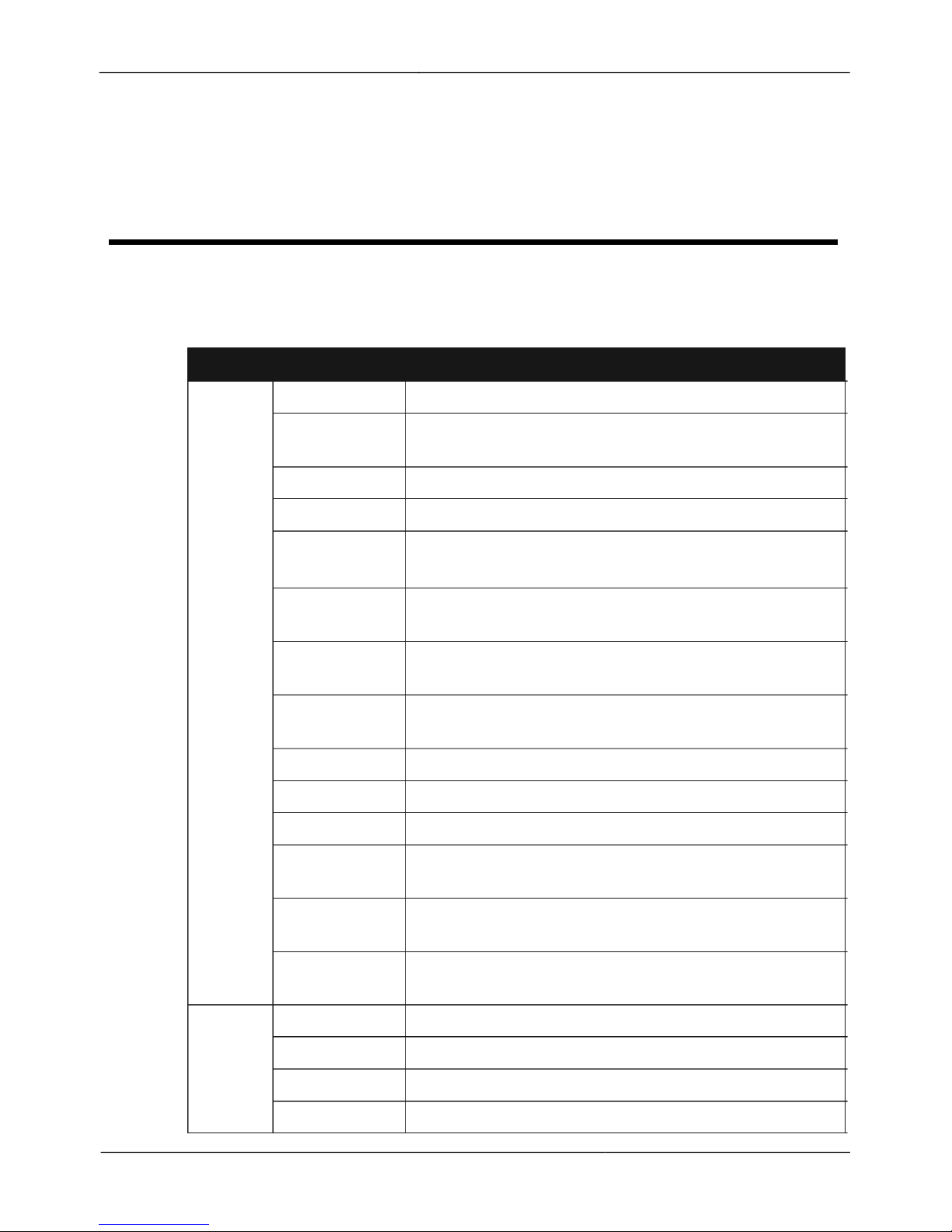
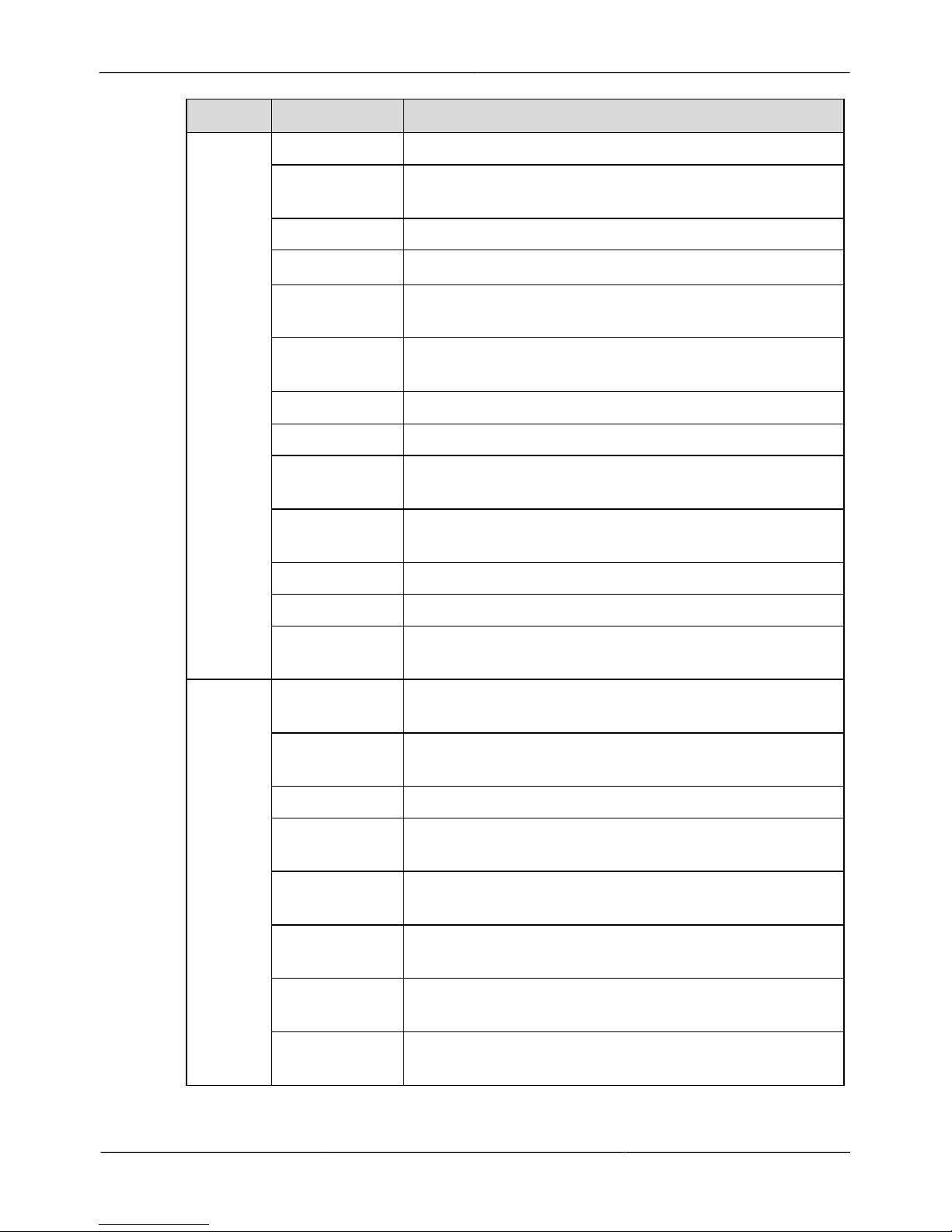
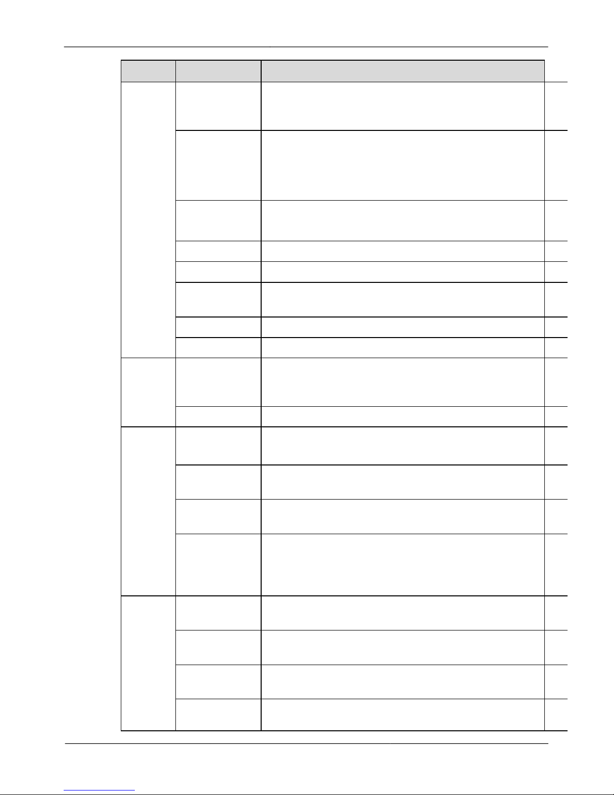
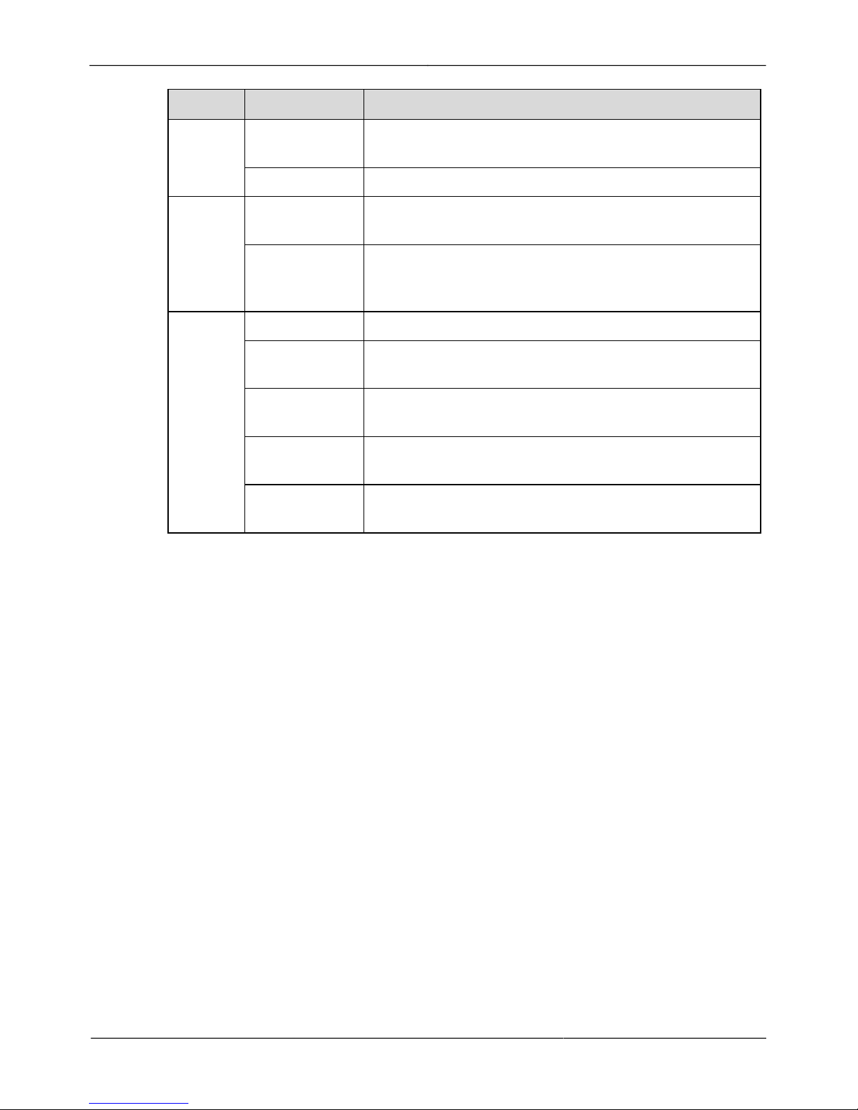
Table 5-1 lists the technical specifications of the camera.
Table 5-1 Technical specifications
Items
Parameters
Details
Camera
Image sensor
1/2.8" CMOS
Effective
pixels
2048(H)
*1536(V)
Digital zoom
16x
Optical zoom
12x
Minimum
illumination
Color: 0.01Lux
B&W: 0.001Lux; IR LED ON: 0Lux
Day/Night
mode
Auto/Color/B/W
Removable
optical filter
Support
Electronic
shutter speed
1/1 s ~1/10000s
Gain control
Auto/Manual
White balance
Auto/Manual
Defogging
Support
Wide dynamic
range
Support
Backlight
compensation
Support
Highlight
compensation
Support
Lens
Focal length
4.7 mm ~56.4mm
Zoom speed
3.8s
Auto iris
Auto/Manual
Focus
Auto/Manual/PUSH
Page 23
IR Network High Speed Dome
User Manual
5 Technical Specifications
Issue V1.0 (2015-09-30)
17
Items
Parameters
Details
PTZ
Pan/tilt Range
Pan: 0°~360°endless; Tilt: -10°~90°auto flip
Manual
Control Speed
Pan: 0.01°/s -180°/s; Tilt: 0.01°/s -90°/s
Preset Speed
Pan: 180°/s; Tilt: 90°/s
PTZ precision
<0.2°
Proportional
zoom
Rotation speed can be adjusted automatically according
to zoom multiples
Number of
presets
300
Patrol
12 patrols, up to 32 presets per patrol
Scan
12
Track memory
6, each track records at most 5 minutes or
1000 commands.
Power-off
memory
Support
Guard position
Activate Preset/cruise/scan/track
3D positioning
Support
Coordinate
display
Support
External
interface
Network
interface
RJ45 10/100Base-Tself-adaptive Ethernet port
Power
interface
DC12V/PoE+
RS485
Not supported
Alarm
interface
Passive input type, 2 alarm input and 1alarm
output(optional)
Audio
interface
1 audio input and 1 audio output(optional)
Bidirectional
Intercom
Support
CVBS
interface
Not supported
SD card
interface
Micro SD
Page 24
IR Network High Speed Dome
User Manual
5 Technical Specifications
18
Issue V1.0 (2015-09-30)
Items
Parameters
Details
Video
Video
encoding
format
H.264(BP/MP/HP)/MJPEG
Resolution
50Hz: 25fps
60Hz: 25fps
Primary stream: 2048*1536, 1080P/720P
Secondary stream: 640*360/D1/CIF/ VGA/QVGA
Frame rate
Primary stream; 300W: 500kbps~12Mbps
Secondary stream: 100kbps~4Mbps
Multi-stream
Support for double stream
Stream type
VBR/CBR
Synchronous
mode
Internal synchronization
S/N Ratio
50dB~55dB
DNR
Auto/Manual (support for 3D noise reduction)
Audio
Audio
encoding
format
Support for G711, RAW_PCM
Audio bit rate
8kbps (G.711),16kbps (RAW_PCM)
Network
Network
protocol
IPv4/IPv6、RTSP/RTP/RTCP、TCP/UDP、HTTPS、
DHCP、DNS、DDNS、PPPoE、SMTP
Heartbeat
mechanism
Support
Streaming
mode
Unicast
Number of
users in
concurrent
access
6
Function
Region of
interest ROI
Support
Video
buffering
Support
User rights
Two roles: administrator and common users. The
administrator can assign common user different rights.
Support for
SDK
Linux C/Windows C&C++SDK
Page 25
IR Network High Speed Dome
User Manual
5 Technical Specifications
Issue V1.0 (2015-09-30)
19
Items
Parameters
Details
Storage
Local storage
type
Support for SD, SDHC card
Capacity
64G
Web
Language
English, Simplified Chinese, Spanish, Portuguese,
Polish and Italian
Management
and
maintenance
Management and maintenance via the web is not
supported. An independent upgrade tool is available.
Environ
mental
features
Power supply
DC12V/PoE+
Power
consumption
Max 22W
Operating
temperature
-40℃~+60℃
Operating
humidity
<90% (non-condensing)
Protection
level
IP66, TVS4000V
Page 26
20
Issue V1.0 (2015-09-30)
IR Network High Speed Dome
User Manual
6 Troubleshooting
6 Troubleshooting
Table 6-1 describes the common faults and solutions.
Table 6-1 Common faults and solution
Problems
Possible Causes
Remedies
No action when
power is switched
on
Power supply fault
Replace power supply
Bad power supply connection
Re-connect
Transformer damaged
Replace
Abnormal selfcheck. Images with
noise
Mechanical failure
Repair
Camera inclined
Reinstall
Power supply insufficient
Replace
Normal self-check
but no images
Video signal fault
Reinstall
Bad video connection
Re-connect
Camera damaged
Replace camera
Poor image
Bad video connection
Re-connect
Power supply insufficient
Replace
Dome camera out of
control
Self-check error
Reboot camera
Bad control connection
Reconnect Ethernet cable
Bad matrix control
Reboot
Lens Control
Issues
In manual state
Use the control
command to set the lens
of dome into
auto/manual state.
Page 27
Issue V1.0 (2015-09-30)
21
IR Network High Speed Dome
User Manual
A Lightning Proof and Surge Signal Proof
A Lightning Proof and Surge Signal Proof
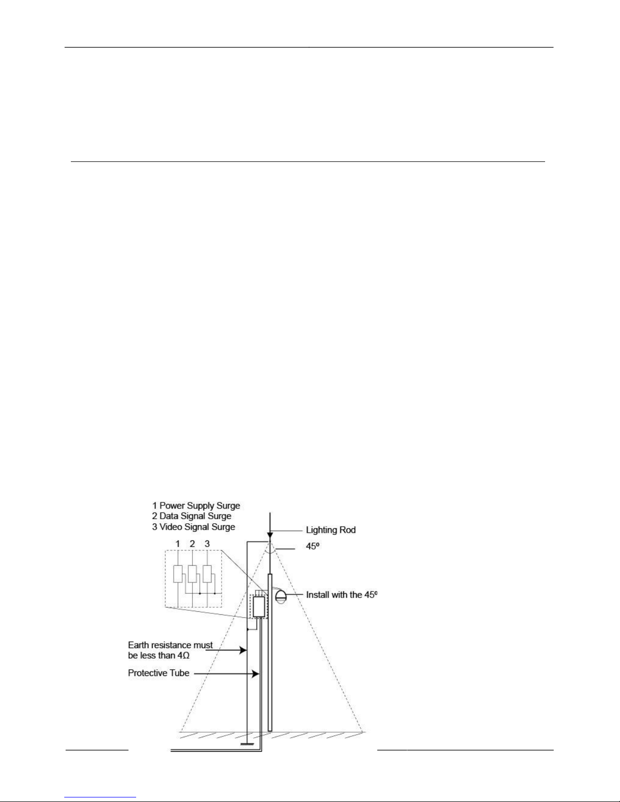
The product adopts TVS lightning proof technology to prevent damage by
lightning strike below 1500 W and impulse signals such as surges; however, it is
also necessary to abide by the following precautions to ensure electrical safety
based on practical circumstances:
!
Keep the communication cables at least 50 meters away from high voltage
equipment or cables.
!
Install outdoor cable lays under eaves as much as possible.
!
In open areas, shield cables in steel tubing and conduct a single point ground to
the tube. Trolley wire is forbidden in such circumstances.
!
In strong thunderstorms or high faradic zones (such as a high voltage
transformer substation), extra strength lightning proof equipment must be
installed.
!
Take the building lightning proof requirements into account to design the lightning
proof and grounding of outdoor equipment and cable laying-out in accordance with
the national and industrial standards.
!
The system must be grounded with equal potentials. The earth ground connection
must satisfy the anti-interference and electrical safety requirements and must not be
short connected with high voltage electricity net. When the system is grounded
separately, the resistance of down conductor should be ≤ 4Ω and the sectional area
of down conductor should be ≤25mm
2
(refer to Figure E.1).
Page 28
22
Issue V1.0 (2015-09-30)
IR Network High Speed Dome
User Manual
B Hazardous Substance Declaration
B Hazardous Substance Declaration
Component
Hazardous Substance or Element
Lead
(Pb)
Mercury
(Hg)
Cadmium
(Cd)
Hexavalent
Chromium
(Cr6+)
Polybrominated
Biphenyls (PBB)
Polybrominated
Diphenyl Ethers
(PBDE)
Structural
part
× ○ ○ ○ ○ ○
Board/circuit
module
× ○ ○ ○ ○ ○
Cable
connector
× ○ ○ ○ ○ ○
Accessories
× ○ ○ ○ ○ ○
○: indicates that the concentration of the hazardous substance in all homogeneous substances of the
component is within the limit specified in SJ/T 11363-2006 Requirements for Concentration
Limits for Certain Hazardous Substances in Electronic Information Products.
×: indicates that the concentration of the hazardous substance in at least one homogeneous substance
of the component exceeds the limit specified in SJ/T 11363-2006 Requirements for Concentration
Limits for Certain Hazardous Substances in Electronic Information Products.
101-500-0162-01
 Loading...