

Page 1
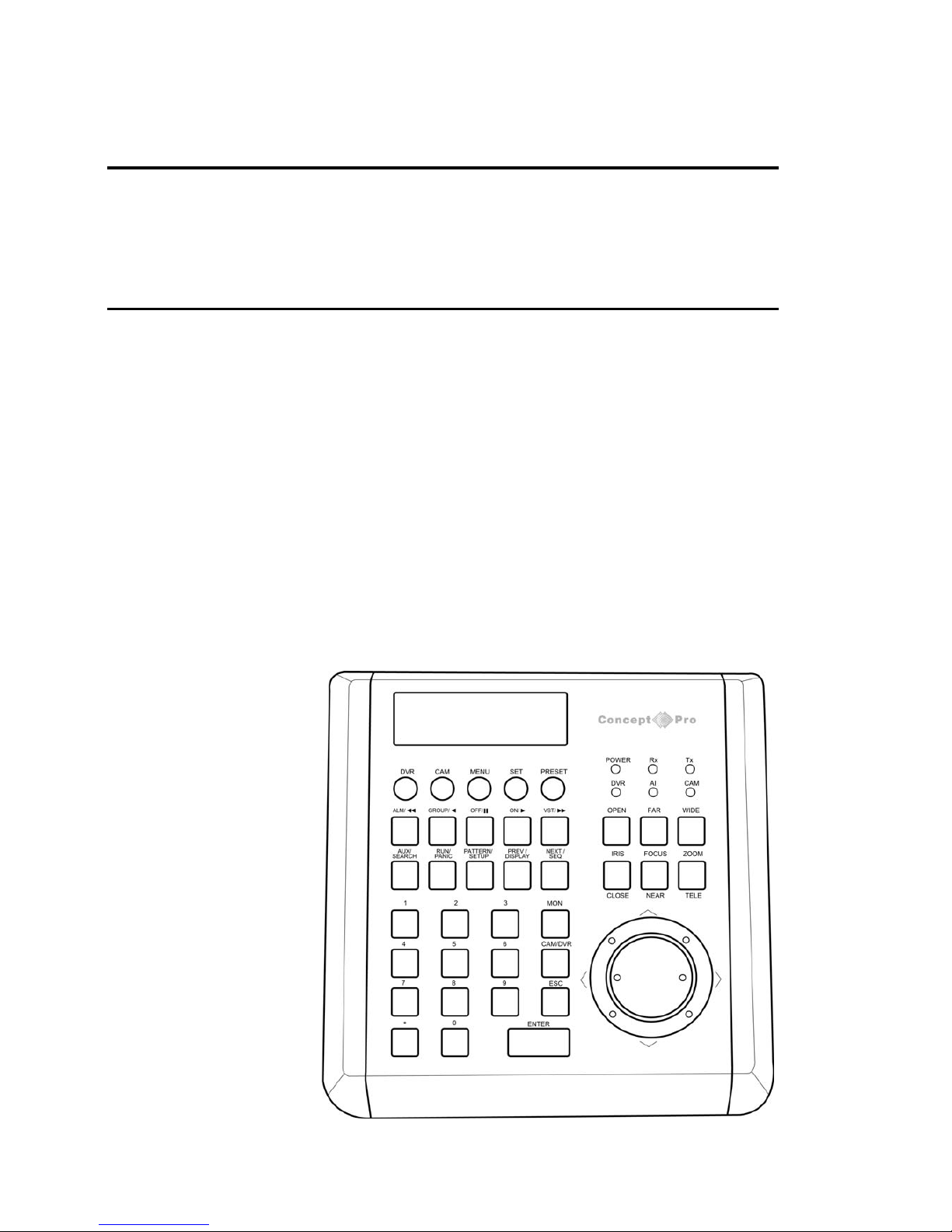
Concept Pro VA-KBDPRO+
3 Axis PTZ / DVR control keyboard
User Manual
Page 2

Contents
Key features 1
Example System configuration 1
Operation modes 2
Getting started 2
Programming the keyboard
Matrix setup 3
DVR setup 3
Camera Setup 4
Key buzzer 5
Key ID 5
Key level 5
Monitor range 5
Camera range 5
DVR range 5
Change default password 5
Reset factory defaults 5
Keyboard operation
CAM mode 6
DVR mode 7
DVR / AI mode 7
Page 3
Key features
Flexible configuration
The VA-KBDPRO+ supports multiple telemetry protocols for compatibility with a wide range of PTZ devices.
Protocols and baudrates can be set globally or individually for each PTZ ID
DVR control
The VA-KBDPRO+ is designed to control all the main functions of one or more Concept Pro VXM4 DVR systems
Matrix support
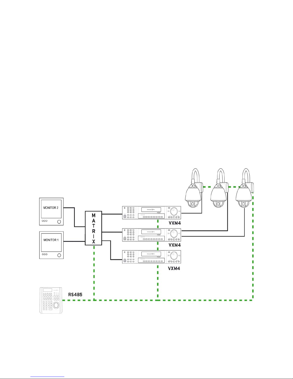
Concept Pro matrix systems can be used wit h the VA-KBDPRO+ for full camera / VXM4 input switching and
monitor output control
Mixed mode (Associate ID) control
The VA-KBDPRO+ can be programmed to control specific PTZ IDs depending on which VXM4 ID and input
channel is selected
1
Example system configuration
Page 4
Operation modes
The VA-KBDPRO+ has 3 operating modes which
are used depending on the system configuration
1. CAM mode
In CAM mode, the VA-KBDPRO+ functions as a
standard PTZ telemetry controller.
The operator can select individual telemetry
devices to control and can also access all features
of those telemetry devices, such as presets,
patterns, groups and menu setup.
If a Concept Pro matrix is connected, as each
camera ID is selected, the matrix will
automatically sw itch to the corresponding input.
Depending on t he matrix configuration, multiple
monitor outputs can also be controlled.
2. DVR mode
In DVR mode, the VA-KBDPRO+ is used to
control all the key functions of one or more
Concept Pro VXM4 digital recorders.
The operator can select individual VXM4s and
select channels, choose display modes, playback
footage or setup the DVR
If a Concept Pro matrix is connected, as each
DVR ID is selected, the matrix will automatically
switch to the corresponding input.
Depending on t he matrix configuration, multiple
monitor outputs can also be controlled.
3. DVR / AI mode
In DVR / AI mode, the VA-KBDPRO+ c an control
telemetry devices and VXM4 channel select ion.
The operator chooses a DVR ID and a particular
channel input to view full screen, and the VAKBDPRO+ automatically selects the associated
speed dome ID. This can then be controlled
directly from the keyboard rather than the DVR
front panel.
If a Concept Pro matrix is connected, as each
DVR ID is selected, the matrix will automatically
switch to the corresponding input.
Depending on t he matrix configuration, multiple
monitor outputs can also be controlled.
Full DVR / AI mode operation must be
programmed through the keyboard setup menu
and is described on page 3
Getting started
Please note: all necessary connections must be
made before applying power to the VA-KBDPRO+
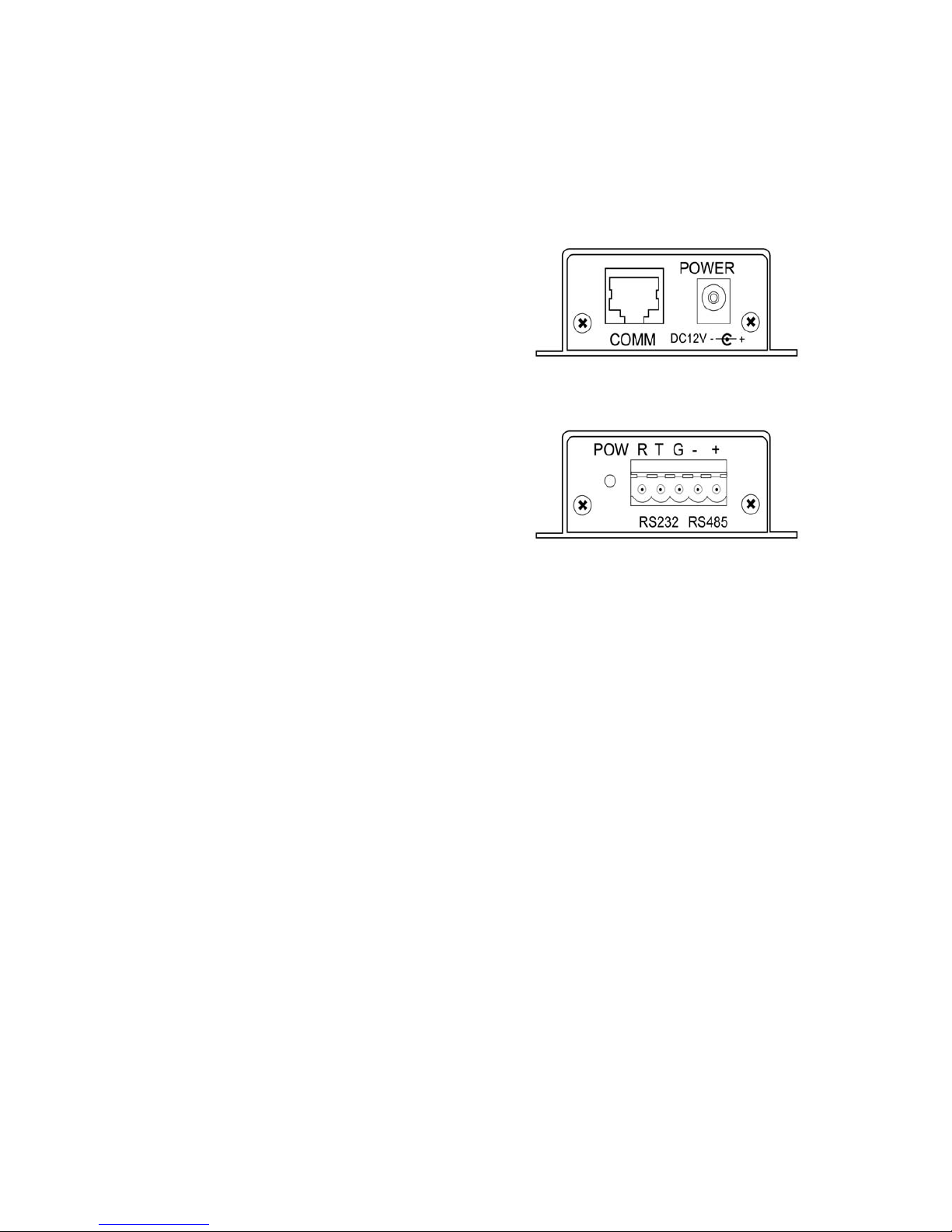
• Connect the supplied CAT5 lead between the
junction box and the VA-KBDPRO+
• Using the 5 way multi plug, connect ‘-’ to the
negative side of the telemetry line and ‘+’ to the
positive side
• If VXM4 control is required, RS485 telemetry
must be connected to the VXM4 via its RS232
port using a VXM4-RS232CONV serial converter
• The RS232 connections on the VA-KBDPRO+
junction box are reserved and should not be used
• Connect power to the VA-KBDPRO+. T he VAKBDPRO+ performs its self test and displays
the startup screen
MONITOR CAM
001 001
VER30<01>
System Keyboard
Press the MENU key to begin normal operation
– the default operation mode is CAM for normal
control of PTZ devices
2
Page 5

Programming the keyboard
To access the keyboard setup, press the MENU
key – the keyboard will prompt for a password
PASSWORD:
**********
Enter t he default password of 9876543210 and
press ENTER. The setup menu is displayed
SET MATRIX:
>SET_PROTOCOL>
To navigate the menu, move the joystick up/down
pressing ENTER to select menu items or ESC to
exit menu items
Matrix setup
SET PROTOCOL
Enter t he keyboard setup menu and use the
joystick to highlight SET MATRIX. The cursor
flashes next to SET_PROTOCOL
SET MATRIX:
>SET_PROTOCOL>
Press ENTER and then twist the joystick left /
right to select the required protocol. Press ENTER
to accept the new protocol setting or ESC to
discard. If using a Concept Pro matrix system, the
protocol should be set to T_VC
Matrix setup
SET BAUDRATE
Enter t he keyboard setup menu and use the
joystick to highlight SET MATRIX. The cursor
flashes next to SET_PROTOCOL. Twist the
joystick right to change the display to
SET_BAUDRATE
SET MATRIX:
>SET_BAUDRATE>
Press ENTER and then twist the joystick left /
right to select the required baudrate. Press
ENTER to accept the new baudrate setting or
ESC to discard. If using a Concept Pro matrix
system, the baudrate should be set to 9600
DVR setup
SET BAUDRATE
Enter t he keyboard setup menu and use the
joystick to highlight SET DVR. The cursor flashes
next to SET_BAUDRATE
SET DVR:
>SET_BAUDRATE>
Press ENTER and then twist the joystick left /
right to select the required baudrate. Press
ENTER to accept the new baudrate setting or
ESC to discard. If using a Concept Pro VXM4, the
baudrate should be set t o 9600
DVR setup
SET ASSOCIATE
Enter t he keyboard setup menu and use the
joystick to highlight SET DVR. The cursor flashes
next to SET_BAUDRATE. Twist the joystick right
to change the display to SET_ASSOCIATE
SET DVR:
>SET_ASSOCIATE>
Press ENTER to display the set associate ID
screen
ID:01 OUT:0001
CH:01 CAM:0001
ID:01 / OUT:0001 – If a Concept Pro matrix is
connected, these two values determine which
matrix channel (OUT) is switched for a particular
DVR (ID).
For example, if a VXM4 with an ID of 7 is
connected to matrix channel 2, set ID to 07 and
OUT to 0002
CH:01 / CAM:0001 – if PTZ devices are
connected to the DVR, these values specifiy
which PTZ ID is connected to which DVR input
channel.
For example, if a speed dome with ID 32 is
connected to DVR input 7, set CH t o 07 and CAM
to 0032
Use the joystick to select the value and enter a
new value using the numeric keypad. Press
ENTER to save changes.
3
Page 6

Camera setup
SET PROTOCOL
Enter t he keyboard setup menu and use the
joystick to highlight SET CAMERA. The cursor
flashes next to SET_PROTOCOL
SET CAMERA:
>SET_PROTOCOL>
Press ENTER to display the SET PROTOCOL
screen
ALL :>VC
0001:>VC
Protocols can be set globally or for each individual
channel.
To set protocol globally, move the joystick
up/down so that the cursor flashes on the ‘>’
symbol next to ALL :
ALL :▓VC
0001:>VC
Twist the joystick left / right to select the required
protocol and press ENTER to confirm. Press ESC
to return to the SET CAMERA menu
To set protocol for each individual channel, move
the joystick up/down so that the cursor flashes on
the ‘0’ of 0001:
ALL :>VC
▓001:>VC
Use the numeric keypad to enter the 4 digit
camera ID to change, eg ‘0002’. The cursor now
moves to protocol selection
ALL :>VC
0002:▓VC
Twist the joystick left / right to select the required
protocol and press ENTER to confirm. The I D
automatically advances t o the next number.
Continue setting up protocols for all camera IDs
as required and then press ESC to return to the
SET CAMERA menu
Camera setup
SET BAUDRATE
Enter t he keyboard setup menu and use the
joystick to highlight SET CAMERA. The cursor
flashes next to SET_PROTOCOL. Twist the
joystick right to change the display to
SET_BAUDRATE
SET CAMERA:
>SET_BAUDRATE>
Press ENTER to display the SET BAUDRATE
screen
ALL :>9600
0001:>9600
Baudrates can be set globally or for each individual
channel.
To set baudrate globally, move the joystick
up/down so that the cursor flashes on the ‘>’
symbol next to ALL :
ALL :▓9600
0001:>9600
Twist the joystick left / right to select the required
baudrate and press ENTER t o confirm. Press ESC
to return to the SET CAMERA menu
To set baudrate for each individual channel, move
the joystick up/down so that the cursor flashes on
the ‘0’ of 0001:
ALL :>9600
▓001:>9600
Use the numeric keypad to enter the 4 digit
camera ID to change, eg ‘0002’. The cursor now
moves to baudrate select ion
ALL :>9600
0002:▓9600
Twist the joystick left / right to select the required
baudrate and press ENTER t o confirm. The ID
automatically advances t o the next number.
Continue setting up baudrates for all camera IDs
as required and then press ESC to return to the
SET CAMERA menu
4
Page 7

Key Buzzer
The VA-KBDPRO+ has an internal key press
buzzer which can be enabled or disabled as
required. Enter the keyboard setup menu and use
the joystick to highlight KEY BUZZER. The cursor
flashes next to ENABLE BEEP
KEY BUZZER:
▓ENABLE BEEP
Twist the joystick left / right to toggle between
ENABLE BEEP / DISABLE BEEP and press
ENTER to confirm
Set Key ID
When multiple k eyboards are used on the same
matrix system, each keyboard must have a unique
ID. Enter the keyboard setup menu and use the
joystick to highlight SET KEY ID.
SET KEY ID:
▓01<01-63)
Use the numeric keypad to enter a KEY ID v alue
and press ENTER to accept
Set Key Level
When multiple k eyboards are used on the same
matrix system, keyboards can be assigned a key
level where 01 is the highest and 15 is the lowest.
For example, a matrix operation performed by one
operator cannot be changed by another operator
unless they have a higher key level. Enter the
keyboard setup menu and use the joystick to
highlight SET KEY LEVEL.
SET KEY LEVEL:
▓01<01-15)
Use the numeric keypad to enter a KEY LEVEL
value and press ENTER to accept.
Set monitor range
Enter t he keyboard setup menu and use the
joystick to highlight SET MON RANGE.
SET MON RANGE:
>▓00-239<000-239
Use the numeric keyboard to enter first and last
values according to the number of monitors
connected to the system, eg 001-009
Set camera range
Enter t he keyboard setup menu and use the
joystick to highlight SET CAM RANGE.
SET CAM RANGE:
>▓00-254<000-254
Use the numeric keyboard to enter first and last
values according to the number of cameras
connected to the system, eg 001-072
Set DVR range
Enter t he keyboard setup menu and use the
joystick to highlight SET DVR RANGE.
SET DVR RANGE:
>▓00-254<000-254
Use the numeric keyboard to enter first and last
values according to the number of monitors
connected to the system, eg 001-006
Change default password
The VA-KBDPRO+ default password can be
changed to prevent unauthorised access. Enter
the keyboard setup menu and use the joystick to
highlight CHANGE PASSWORD.
CHANGE PASSWORD:
>▓876543210
Use the numeric keypad to enter a new 10 digit
password and press ENTER t o confirm
Reset factory defaults
Enter t he keyboard setup menu and use the
joystick to highlight RESET DEFAULT_I?
RESET DEFAULT_I?:
>▓*********
Use the numeric keypad to enter the factory reset
password of 0123456789 and press ENTER
5
Page 8

Keyboard operation
CAM mode
Please note that all the operation examples given
here are for the Concept Pro VHSD-8XX series of
speed domes. For any other type of PTZ
equipment, reference should be made to its user
manual for the appropriate command sequences.
To place the keyboard in to CAM mode, press the
CAM button.
MONITOR CAM
001 001
To select a particular camera ID, press
CAM/D VR – XXX – ENTER
Where XXX is a numeric camera ID
To control the selected camera, move the joystick
up/down/left/right – the further the joystick is
moved, the faster the movement. Twist the
joystick clockwise to zoom in and anti-clockwise
to zoom out. The zoom level can also be
controlled by pressing the WIDE and T ELE buttons
Managing presets
To program a preset position, move the speed
dome to the desired scene and zoom level and
press SET – XXX – ENTER, where XXX is a
preset position between 1 and 128 (but note that
preset 95 is reserved and cannot be used)
To move the speed dome to a preset position
that’s already been programmed, press PRESET –
XXX – ENTER where XXX is a preset position
between 1 and 128 (but note that preset 95 is
reserved and cannot be used)
To clear a preset position from the speed dome
memory, press ESC – XXX – ENTER where XXX
is a preset posit ion between 1 and 128 (but note
that preset 95 is reserved and cannot be used)
Runni ng pattern tours, variable speed
tracking and gr oup functions
To start a pattern tour, press PRESET –13X –
ENTER, where X is a predefined pattern tour
number between 1 & 4
To start a VST f unction, press PRESET –14X –
ENTER, where X is a predefined VST function
between 1 & 8
To start a group, press PR ESET –15X – ENTER,
where X is a predefined group between 1 & 8
Using the speed dome setup menu
To enter the speed dome menu, press
PRESET – 95 – ENTER
To choose a menu item or change settings within
a menu item, move the joystick up / down
To enter a menu item or confirm a new setting,
press NEAR
To exit a menu item or cancel a new setting,
press FAR
Please refer to the manual supplied with the speed
dome for a detailed explanation of the menu setup
procedures
Additional operations if a matrix is connected
When a particular camera ID is selected on the
keyboard, the appropriate input on the matrix is
automatically switched.
To start / stop a sequence, press t he RUN key
To swit ch to the next camera, press the NEXT key
To swit ch to the previous camera, press the
PREV key
When multiple monitors are connected, individual
cameras can be displayed on different monitors.
To select the required monitor, press
MON – XXX – ENTER
And then select the required camera to be
displayed on that monitor by press ing
CAM/D VR – XXX – ENTER
6
Page 9

Keyboard operation
DVR mode
Please note that this keyboard can only control the
Concept Pro VXM4 range of DVRs
To place the keyboard in to DVR mode, press the
DVR button repeatedly until only the yellow DVR LED
is lit
MONITOR DVR
001 001
To select a particular DVR ID, press
CAM/D VR – XXX – ENTER
Where XXX is a numeric DVR ID
To select channels full screen, press XX – ENTER,
where XX is a channel number between 1 & 16.
The SEARCH, PANIC, SETUP, DISPLAY and SEQ
buttons control t he relevant functions of the VXM4
To navigate through the VXM4 on screen displays (eg
during Setup and Search modes), move the joystick
up / down / left / right and press ENTER and ESC to
select or cancel items respectively.
To enter passwords (eg, during Setup and Search
modes), the keyboard must be switched to numeric
entry mode by pressing t he * key
For example, when the VXM4 prompts for a
password, the f ollowing k ey sequence should be used
* - XXXX - * - ENTER, where XXXX is the password
Note – the * key must be pressed after the password
is entered to switch the keyboard back to normal
operation
When the VXM4 is in playback mode, the five
playback buttons and / or the joystick can be used to
control playback as follows:
Select forward play – move the joystick right or press
►
Select reverse play – move the joystick left or press
◄
Pause playback – press װ
Increase forward / decrease reverse play speed –
press ►► or twist the joystick right
Decrease forward / increase reverse play speed –
press ◄◄ or twist the joystick left
Additional operations if a matrix is connected
When a particular VXM4 ID is selected on the
keyboard, the appropriate input on the matrix is
automatically sw itched according to the DVR / Set
Associate programming (page 3).
When multiple monitors are connected, individual
VXM4s can be displayed on different monitors.
To select the required monitor, press
MON – XXX – ENTER
And then select the required VXM4 to be displayed
on that monitor by pressing
CAM/D VR – XXX – ENTER
Keyboard operation
DVR / AI mode
Please note that this keyboard can only control the
Concept Pro VXM4 range of DVRs.
In DVR/AI mode only individual channels can be
selected full screen. For f ull control of a VXM4,
the standard DVR mode should be used (see
opposite)
To place the keyboard in to DVR/AI mode, press
the DVR button repeatedly until both the yellow
DVR and green AI LEDs are lit
DVR:001 CH:01
MON:001 PTZ:001
To select a particular DVR ID, press
CAM/D VR – XXX – ENTER
Where XXX is a numeric DVR ID
To display an individual c hannel of the selected
DVR full screen and take control of the associated
speed dome, press XX – ENTER, where XX is a
channel number between 1 & 16.
As each channel is select ed full screen, the PTZ
value automatically changes according to the DVR
/ Set Associate programming (page 3)
Full control of the associated speed dome is then
available, including programming and recalling
presets, starting groups, t ours, etc.
Additional operations if a matrix is connected
When a particular VXM4 ID is selected on the
keyboard, the appropriate input on the matrix is
automatically switched according to the DVR / Set
Associate programming (page 3).
When multiple monitors are connected, individual
VXM4s can be displayed on different monitors.
To select the required monitor, press
MON – XXX – ENTER
And then select the required VXM4 to be displayed
on that monitor by pressing
CAM/D VR – XXX – ENTER
7
 Loading...