

Page 1
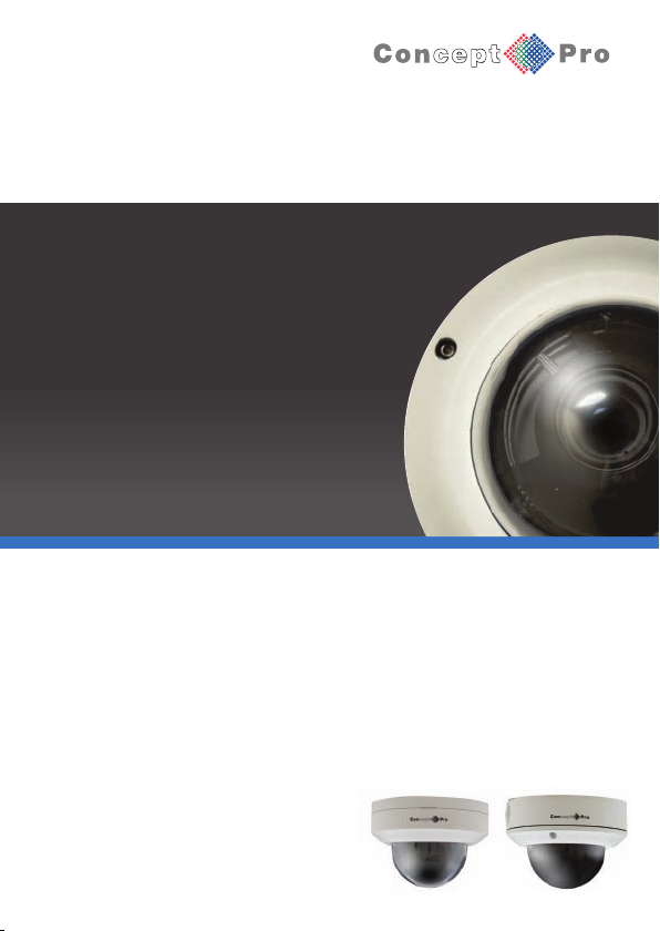
CBP6314DNIR
CBP6324DNIR
CVP9314DNIR
CVP9324DNIR
Infrared Dome Camera
USER MANUAL
Page 2

CAUTION
1. This install ation should be made by a qualified service person and should abide to all local
codes.
2. Avoid installation on a surface subjected to frequent vibration or shocks.
3. Do not opera te the camer a beyond its temperature range or power source ratings.
4. Should any d amage or sus pected damage occur, shutdown the power source, unplu g and
contact your service pro vider.
5. Do not insta ll the camer a under unstable lighting conditions. Severe lighting change or
flicker can cause the ca mera to work improperly.
6. Never use th e camera clo se to a gas or oil leak.
7. Do not disas semble the c amera.
8. Never keep t he camera fa ce to strong light directly, this can damag e the CCD.
9. Ensure all r emovable cov ers are replaced to protect the inner components.
10. Do not insta ll near devi ces which emit a strong electro-magnetic field.
11. Use a dry or damp cloth only for cle aning.
12. Internal dom e only - Do not drop the camera or subject the unit to physical shocks.
PLEASE FOLLO W THE ABOVE CAUTIONS – FAILURE TO DO SO MAY
INVALIDATE THE WARRANTY OR CAUSE SERIOUS INJURY.
Remark: Change s or mo dificat ions no t expres sly app roved by the manufacturer can
cause t he came ra to b e damag ed and become inopera ble. Th is may invalid ate the
user wa rranty.
Page 3
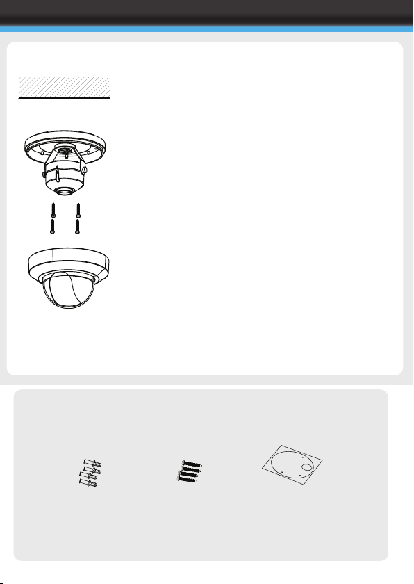
INTERNAL DOME INSTALLATION
CBP Range
FIXING TO A WALL
Ceiling
CBP Range
PACKING CONTENTS
Important: Ensure all cautionary procedures are
observed during installation.
It is recommended the camera is tested during the most
demanding environmental conditions such as low light
or bright sunlight to ensure continuity of effective CCTV
monitoring.
Remove th e camer a unit careful ly from the bo x
reserving the accessory contents in a safe place
Use the s upplied mounti ng temp late to mark t he
space for drilling
Remove th e dome cover u sing a suitabl e coin or
screwdriver
Using the suppli ed fitt ing scr ews, se curely attach the
camera to the drilled surface
Adjust th e tri-a xis gim bal zoo m/focus to giv e the
required image of the area to be monitored.
Replace t he dome cover by push ing fir mly in place
onto the base
Carefully clean the dom e surfa ce with a soft lint
free cloth
Wall Plugs
X4
Fitting Screws
X4
Mounting Template
X1
Page 4
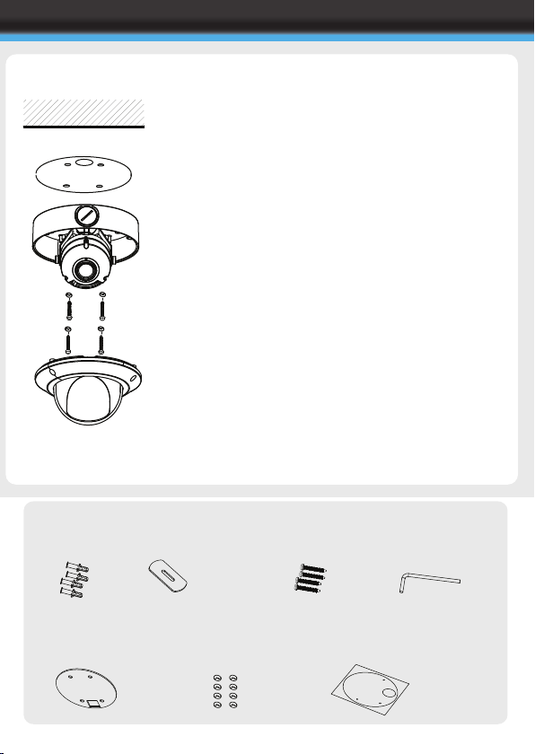
VANDAL RESISTANT DOME INSTALLATION
CVP Range
FIXING TO A WALL
Ceiling
CVP Range
PACKING CONTENTS
Important: Ensure all cautionary procedures are
observed during installation.
It is recommended the camera is tested during the most
demanding environmental conditions such as low light
or bright sunlight to ensure continuity of effective CCTV
monitoring.
Remove th e camer a unit careful ly from the bo x
reserving the accessory contents in a safe place
Use the s upplied mounti ng temp late to mark t he
space for drilling
Remove th e dome cover u sing th e suppl ied dom e
cover screwdriver
Attach th e weath erproof sealin g pad t o the b ase of
the dome with the sticky side against the camera
Using the suppli ed fitt ing scr ews, se curely attach the
camera to the drilled surface
Please note: To ensur e corre ct weat herproo f you
must use the enclosed fitting screws and
weatherproof washers
Adjust th e tri-a xis gim bal zoo m/focus to giv e the
required image of the area to be monitored.
Replace t he dome cover and tig hten th e dome cover
screws using the supplied dome cover screw driver
Carefully clean the dom e surfa ce with a soft lint
free cloth
Wall Plugs
X4
Conduet hole c over
opener
X1
Weatherproof
sealing pad
X1
Fitting Screws
X4
Weatherproof
sealing washer s
X8
Dome cover
screwdriver
X1
Mounting Template
X1
Page 5
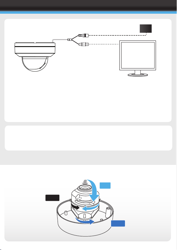
CONNECTION
Connect t he vide o out p ort to your vi deo cab le
running to the monitor / recorder
Check the power supply is of t he corr ect lev el
and connect your power supply into the power
port on the Camera.
View the picture on a monitoring device to
check the power and video connection is
working properly.
Troubleshootin g
Ensure all power and cab le conn ections are cor rect with the Camera and DVR.
If all po wer and cable connect ions are correct and th e camer a pictu re can not be
produced then c ontact your su pplier for tec hnical support .
PSU
Tri-Axis Gimbal
90º
360º
360º
Example shows van dal resistant do me casin g
Page 6
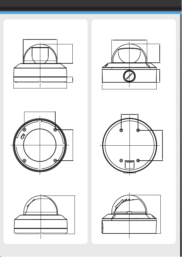
DIMENSIONS
CVP VANDAL RESISTANT RANGECBP INTERNAL DOME RANGE
94.64
147.97
86.00
53.18
15.00
86.00
94.64
51.0135.48
148.39
46.00
82.50
106.10
105.00
Page 7
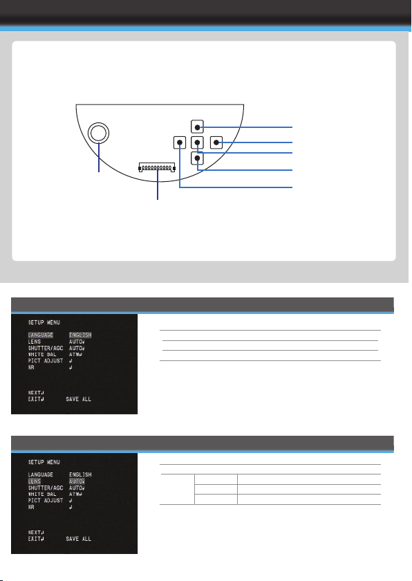
OSD
OSD Controller
RCA SERVICE VIDEO
OUTPUT
LANGUAGE
SERVICE CABLE
(OPTION)
ENGLISH / SPANISH / P ORTUGUESE /
FRENCH / GERMAN / CHINESE /
JAPANESE / RU SSIAN
UP
RIGH T
MENU / E NT ER
DOWN
LEFT
LENS
MANUAL
AUTO TYPE DC
MODE AUTO, OPE N, CLOSE
SPEED 0~255
Page 8
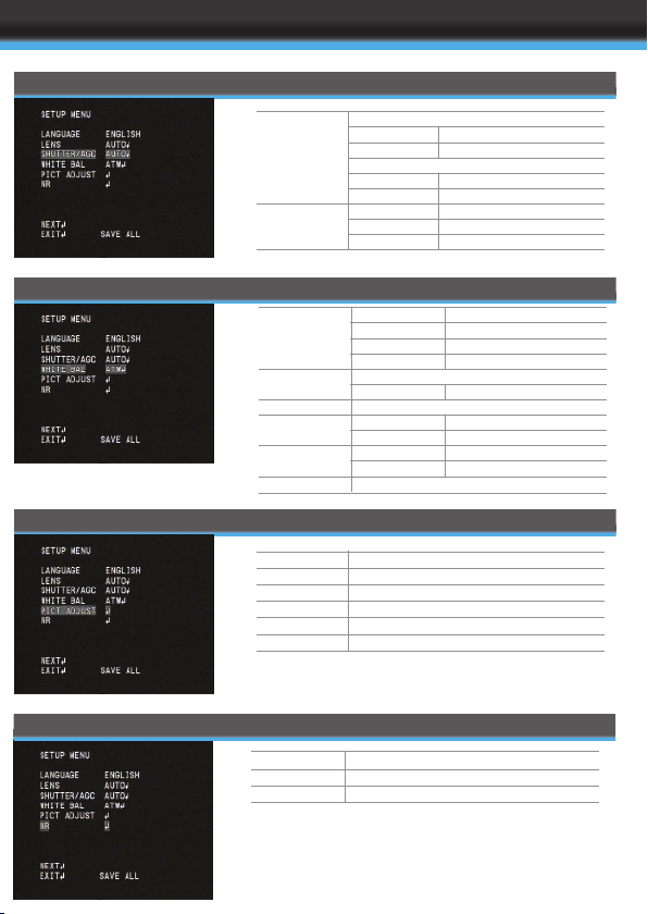
SHUTTER / AGC
WHITE BALANCE
PICT ADJUST
AUTO
MANUAL
ATW
PUSH LOC K
MANUAL LEVEL 0~255
ANTI CR
USER 1 B-GAIN 0~255
R-GAIN 0~255
USER 2 B-G AIN 0~255
R-GAIN 0~255
PUSH
HIGH LUM INANCE
MODE SHUT+AUTO IRIS, AUTO I RIS
BRIGHTNE SS 0~255
LOW LUMI NANCE
MODE AGC, OFF
BRIGHTNE SS 0.25~1.0 0
MODE SHUT+AGC
SHUTTER 1/50~1/1 0000
AGC 6.00~44. 80
SPEED 0 ~255
DELAY CNT 0~255
ATW FRAME X0.50~X2 .00
ENVIRONM ENT INDOOR/O UTDOOR
NR
MIRROR
BRIGHTNE SS
CONTRACT
SHARPNES S
HUE
GRAIN
NR MODE
Y LEVEL
C LEVEL
OFF/ON
0~255
0~255
0~255
0~255
0~255
Y/C, C, Y, OFF
0~15
0~15
Page 9
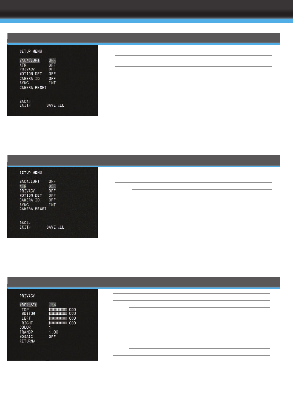
SPECIFICATION
BACKLIGHT
ATR
PRIVACY
OFF/BLC/ HLC
OFF
ON LUMINANCE LOW, MID, HI GH
CONTRAST LOW, MIDLOW, MID,
MIDHIGH, HIGH
OFF
ON AREA SEL 1~4
TOP 0~288
BOTTOM 0~288
LEFT 0~468
RIGHT 0~468
COLOUR 1~8
TRANSP 0.00~1.00
MOSIAC OFF/ ON
Page 10
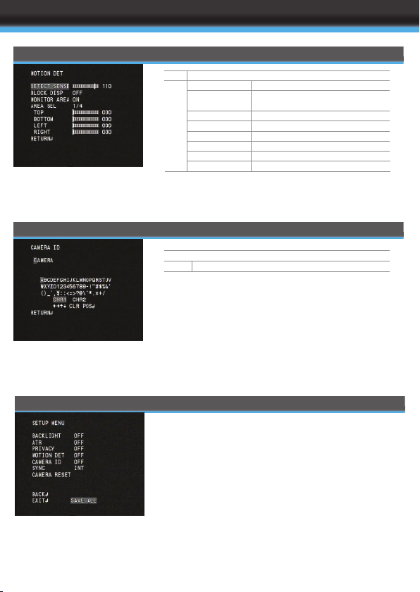
MOTION DETECTION
CAMERA ID
SAVE ALL
OFF
ON DETECT SENSE 0~1 27
BLOCK DI SPLAY OFF/ON/EN ABLE/
SELECT AREA
MONITOR AREA OFF /ON
AREA SELECT 1~4
TOP 0~28 8
BOTTOM 0~288
LEFT 0~288
RIGHT 0~288
OFF
ON OPENS VIRTUAL K EYBOARD
IMPORTANT - PLEASE NOTE:
When all configurations have been made select SAVE
ALL at the bottom of the OSD before exiting
Page 11
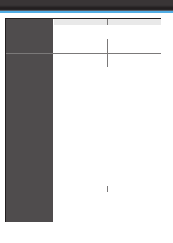
SPECIFICATION
MODEL
Image Senso r
Signal syst em
Effective pixel
Resolution
Min. illmin ation
Lens
Day & Night
S/N Ratio
IR LED
Control Method
ES
White Balan ce
AGC
BLC
DNR
HLC
Privacy Mas king Function
Motion Dete ction
Sync. Mode
Video Output
Power Suppl y
Power Consu mption
Operation Temperature
Dimension
Weight
CBP6314DNIR CBP6324DNIR
1/3" sony S UPER HAD II CCD
PAL/NTSC
PAL: 752(H)*582(V)
NTSC: 768(H )*494(V)
600TV Lines
0.03 Lux/F1 .2 IRE40 (0 Lux IR LEDS ON)
Fixed Lens f=4mm
Software Day night w/o ICR
more than 50dB(AGC Off)
21pcs IR LE DS
Multi-langu age OSD
1/50-1/100, 000sec(PAL)
ATW/ PUSH/ USER1/ USER2/ ANTI CR/Manual/P USG LOCE
AGC Can be adjustable by OSD
1.0V P-P,75 Ohm
DC 12V
-10ºC~ +50º C RH90% MAX
320mA MAX
148x106 (Dx H)
PAL: 976(H)x582(V) ;
NTSC 976(H) x494(V)
650TV Lines in Colour
700TV Lines in B&W
Auto IRIS Vari-f ocal lens
F=2.8-10mm
True day and night With ICR
more than 52dB(AGC Off)
ON/OFF
2D DNR
ON/OFF
4 Zones
4Zones
Internal
DC12V/AC 24 V
650g
Design and spe cificat ion are subject to cha nge wit hout no tice.
Page 12
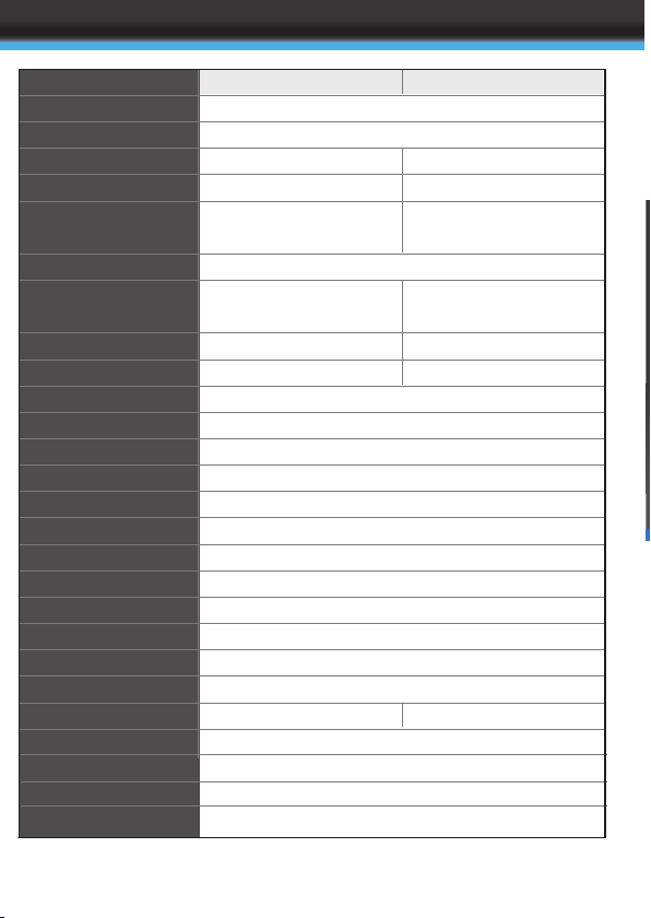
SPECIFICATION
MODEL
Image Senso r
Signal syst em
Effective pixel
Resolution
Min. illmin ation
Lens
Day & Night
S/N Ratio
IR LED
Control Method
ES
White Balan ce
AGC
BLC
DNR
HLC
Privacy Mas king Function
Motion Dete ction
Sync. Mode
Video Output
Power Suppl y
Power Consu mption
Operation Temperature
Dimension
Weight
CVP9314DNIR CVP9324DNIR
1/3" sony S UPER HAD II CCD
PAL/NTSC
PAL: 752(H)*582(V)
NTSC: 768(H )*494(V)
600TV Lines
0.03 Lux/F1 .2 IRE40 (0 Lux IR LEDS ON)
Fixed Lens f=4mm
Software Day night w/o ICR
more than 50dB(AGC Off)
21pcs IR LE DS
Multi-langu age OSD
1/50-1/100, 000sec(PAL)
ATW/ PUSH/ USER1/ USER2/ ANTI CR/Manual/P USG LOCE
AGC Can be adjustable by OSD
1.0V P-P,75 Ohm
DC 12V
-10ºC~ +50º C RH90% MAX
320mA MAX
148.35x10⁵(DxH)
PAL: 976(H)x582(V) ;
NTSC 976(H) x494(V)
650TV Lines in Colour
700TV Lines in B&W
Auto IRIS Vari-f ocal lens
F=2.8-10mm
True day and night With ICR
more than 52dB(AGC Off)
ON/OFF
2D DNR
ON/OFF
4 Zones
4Zones
Internal
DC12V/AC 24 V
950g
Design and spe cificat ion are subject to cha nge wit hout no tice.
Page 13
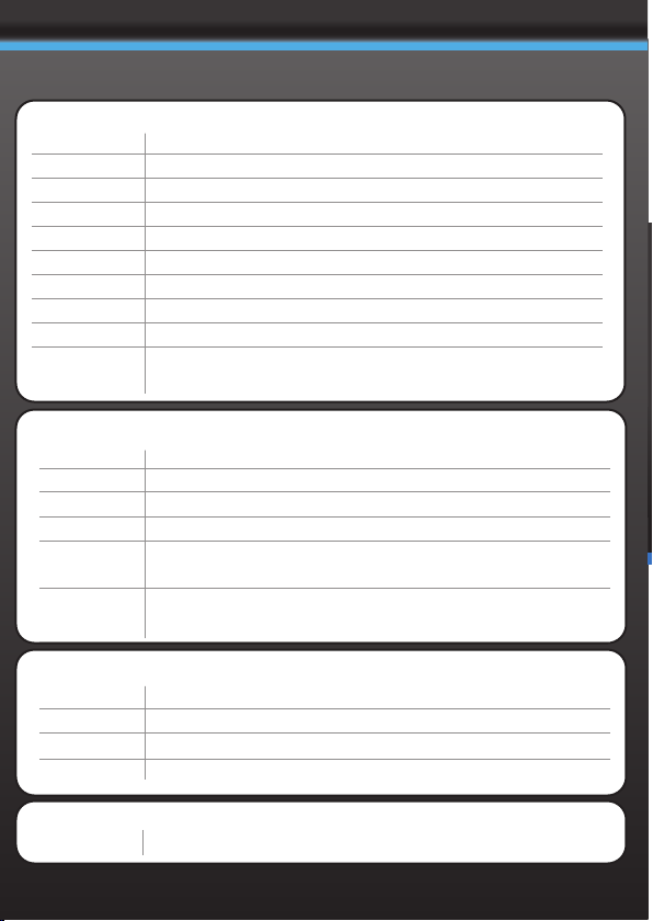
CONCEPT PRO DOME CAMERA RANGE
INTERNAL DOME CAMERAS
CBP3212
CBP5112
CBP5212
CBP4304
CBP5314
CBP4324
CBP6324
CBP6324-B
CBP6324DN
CBP6324WDR
VANDAL RESISTANT DOME CAMERAS
CVP9304
CVP9314
CVP9324
CVP9324DN
CVP9324LL
CVP9324WDR
480TVL, 0.3 Lux, 3.6mm Lens. 90(ø)x62mm
420TVL, 0.3 Lux, 3.6mm Lens, 128(ø)x93mm
480TVL, 0.3 Lux, 3.6mm Lens, 128(ø)x93mm
420TVL, 0.3 Lux, 4mm Lens, 148(ø)x106mm
650TVL, 0.03Lux, 4mm Lens, 148(ø)x106mm
420TVL, 0.3 Lux, 4-9mm Lens,148(ø)x106mm
650TVL, 0.03Lux 2.8-10mm Lens, 148(ø)x106mm
650TVL, 0.03 Lux, 2.8-10mm Lens, 148(ø)x106mm, Black casing
650TVL, 0.03 Lux, 2.8-10mm, Day Night, 148(ø)x106mm
690TVL, 0.01 Lux, 2.8-10mm Lens, Day Night, Wide Dynamic
Range,148(ø)x106mm
420TVL, 0.3 Lux, 4mm Lens, 148.35(ø)x105mm
650TVL, 0.03Lux, 4mm Lens, 148.35(ø)x105mm
650TVL, 0.03Lux 2.8-10mm Lens, 148.35(ø)x105mm
650TVL, 0.03 Lux, 2.8-10mm, Day Night, 148.35(ø)x105mm
600TVL, 0.0002 Lux (DSS/Sens Up on) 2.8-10mm Lens,
148.35(ø)x105mm
690TVL, 0.01 Lux, 2.8-10mm Lens, Day Night, Wide Dynamic Range,
148.35(ø)x105mm
INFRARED DOME RANGE
CBP6314DNIR
CBP6324DNIR
CVP9314DNIR
CVP9324DNIR
VANDAL RESISTANT WALL BRACKET
CVP-BRK
600TVL, 4mm Lens, IR LED, 148(ø)x106mm
650TVL, 2.8-10mm Lens, IR LED, ICR, 148(ø)x106mm
600TVL, 4mm Lens, IR LED, 148.35(ø)x105mm
650TVL, 2.8-10mm Lens, IR LED, ICR, 148.35(ø)x105mm
Wall bracket for use with all CVP dome cameras
Page 14
 Loading...