

Page 1
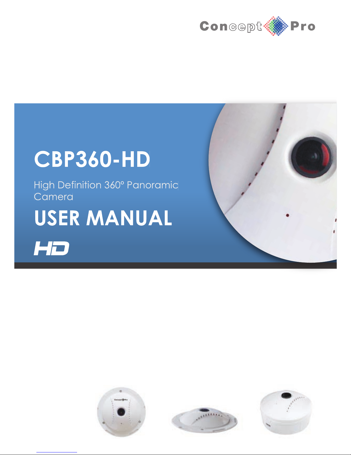
CBP360-HD
High Definition 360º Panoramic
Camera
USER MANUAL
Page 2

1. This installation should be made by a qualified service person and should abide to all local
codes.
2. Avoid installation on a surface subjected to frequent vibration or shocks.
3. Do not operate the camera beyond its temperature range or power source ratings.
4. Should any damage or suspected damage occur, shutdown the power source, unplug and
contact your service provider.
5. Do not install the camera under unstable lighting conditions. Severe lighting change or
flicker can cause the camera to work improperly.
6. Never use the camera close to a gas or oil leak.
7. Do not disassemble the camera.
8. Never keep the camera face to strong light directly, this can damage the sensor.
9. Ensure all removable covers are replaced to protect the inner components.
10. Do not install near devices which emit a strong electro-magnetic field.
11. Use a dry or damp cloth only for cleaning.
12. Internal dome only - Do not drop the camera or subject the unit to physical shocks.
PLEASE FOLLOW THE ABOVE CAUTIONS – FAILURE TO DO SO MAY
INVALIDATE THE WARRANTY OR CAUSE SERIOUS INJURY.
Remark: Changes or modifications not expressly approved by the manufacturer can
cause the camera to be damaged and become inoperable. This may invalidate the
user warranty.
CAUTION
Page 3
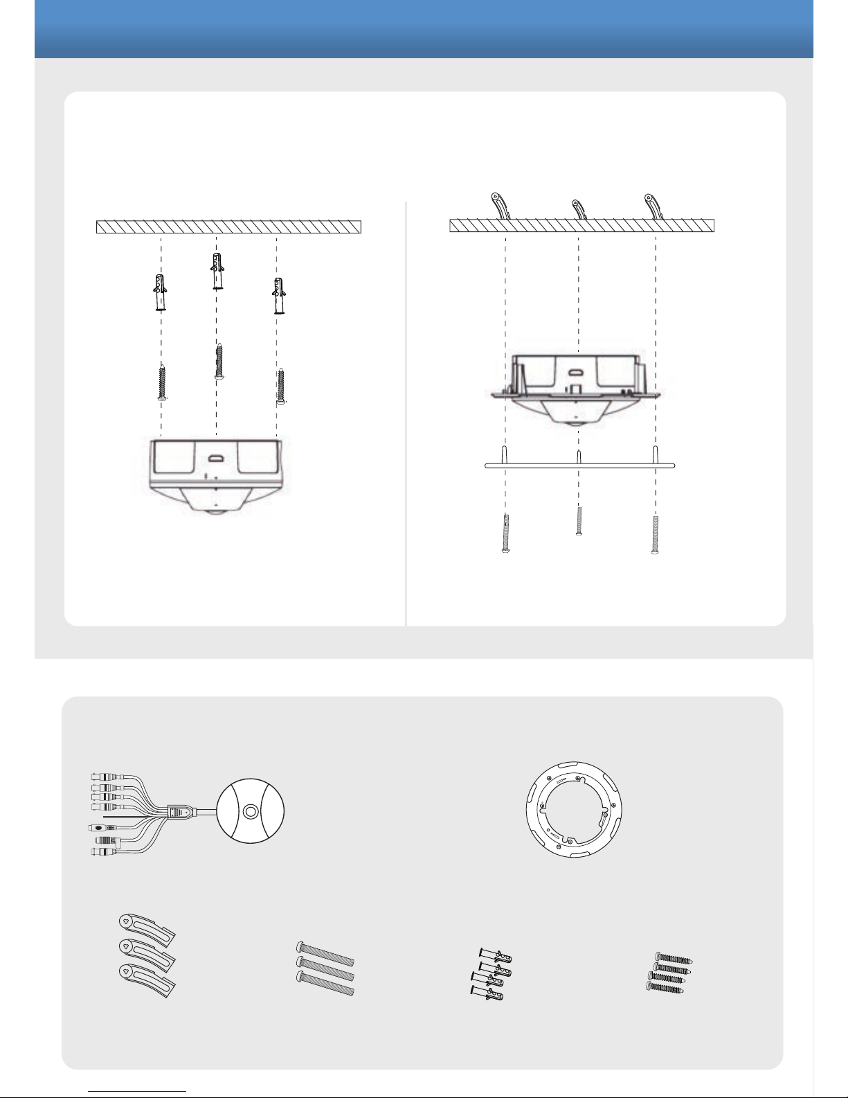
INSTALLATION
PACKING CONTENTS
SURFACE MOUNT FLUSH MOUNT
Wall Plugs
X4
Ceiling Screws
X3
Body Camera
X1
Ceiling Cover
X1
Ceiling Screws
Ceiling
Screws
Ceiling
Ceiling
Screw
Fitting
Screw
Wall
plugs
X3
Fitting Screws
X4
Ceiling
Cover
Ceiling
Page 4
1
2
3
4
5
6
7
8
9
10
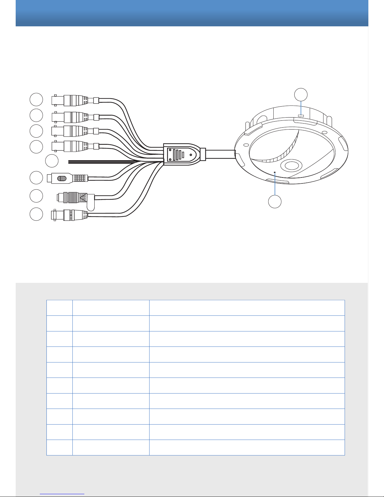
Label1
Label2
Label3
Label4
RS485 cable
RCA cable
Power cable
SDI cable
HDMI connector
Microphone
Camera 1 CVBS(BNC) output
Camera 2 CVBS(BNC) output
Camera 3 CVBS(BNC) output
Camera 4 CVBS(BNC) output
Purple + / white - (Pelco D, 9600)
Audio output to speaker or DVR audio input
DC12V
SDI connector output (BNC gold color)
HDMI output to connect to a HDMI monitor
Pinhole type microphone built in
CONNECTIONS
1
2
3
4
5
10
9
6
7
8
Page 5
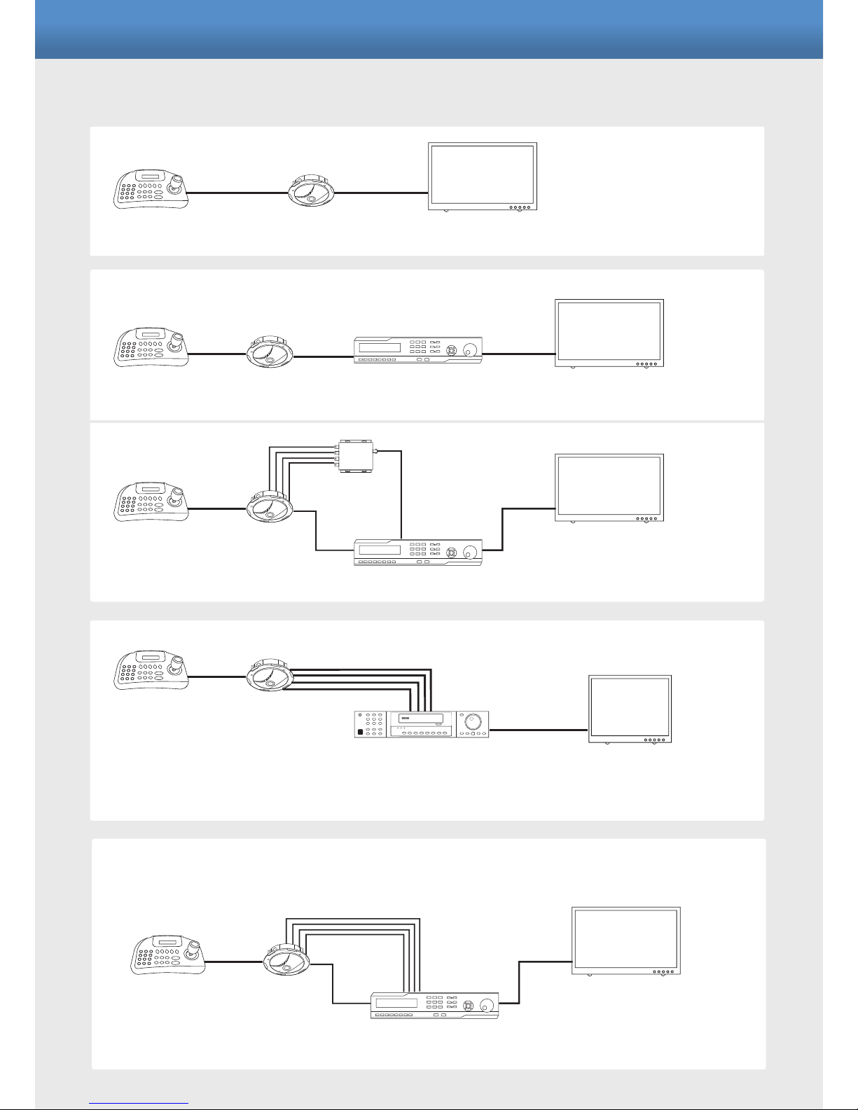
This 360° camera can be installed in many different configuration.
Without DVR
HD-SDI DVR
Analogue DVR
Hybrid HD-SDI and Analogue DVR
CONFIGURATIONS
KEYBOARD CBP360-HD 16:9 1080p Monitor
HDMI CABLE
RS485
CBP360-HD HD-SDI DVR 16:9 1080p Monitor
HDMI / VGA
RS485 HD-SDI
KEYBOARD
CBP360-HD
ANALOGUE DVR
4:3 Monitor
HDMI / VGA / BNC
RS485
KEYBOARD
CBP360-HD
VHD-SD4-CONV
HD-SDI DVR
16:9 1080p Monitor
HDMI / VGA
RS485
HD-SDI
Analogue to HD-SDI
HD-SDI
KEYBOARD
CBP360-HD
VHDR HYBRID DVR
16:9 1080p Monitor
HDMI / VGA
RS485
HD-SDI
ANALOGUE
KEYBOARD
Page 6
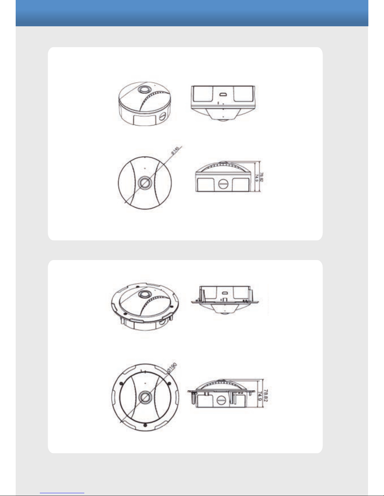
DIMENSIONS
Page 7
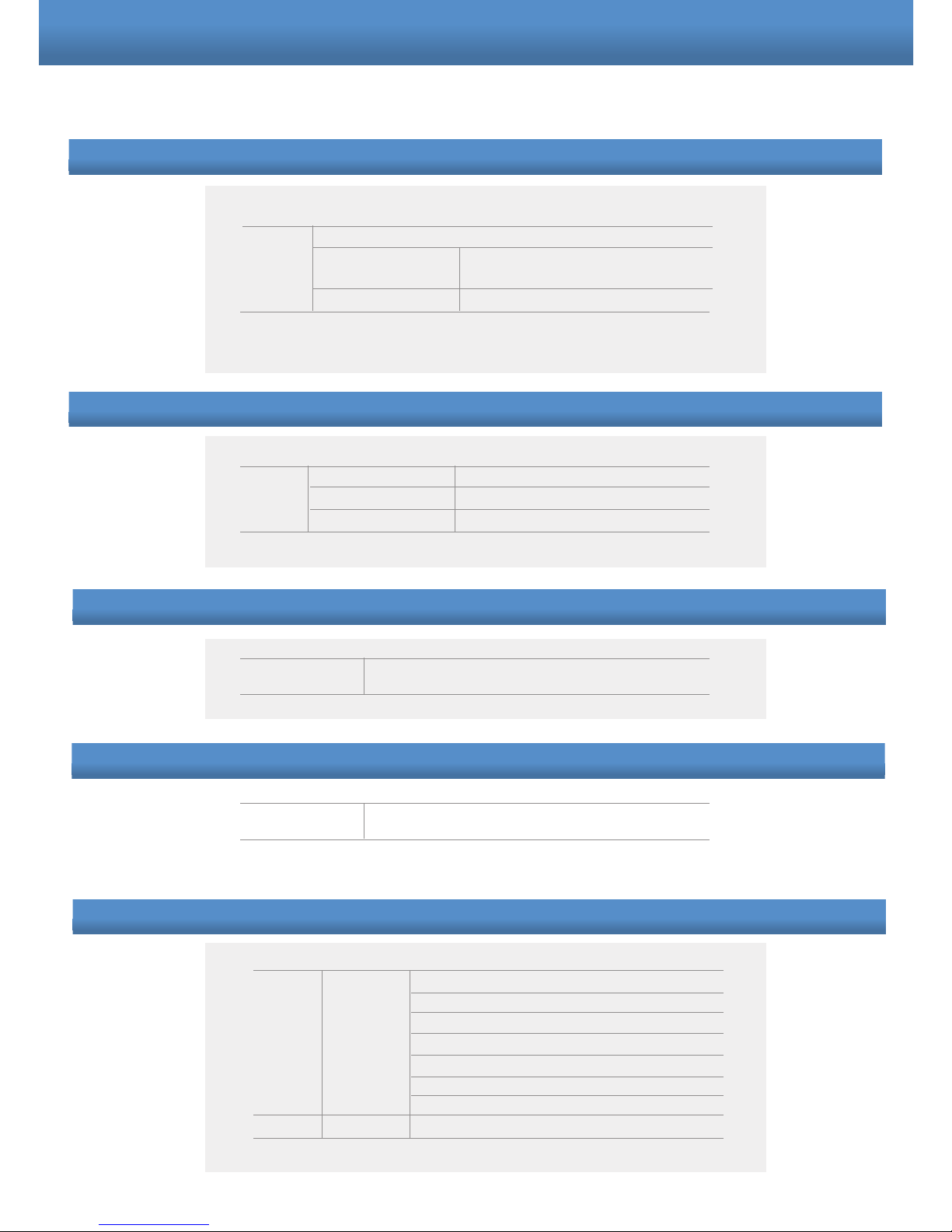
OSD (On Screen Display)
AE (Auto Exposure)
AE 50Hz: PAL /60Hz:NTSC
SHUTTER SPEED
Return
X3; X2; X1; AUTO; 1/100; 1/120;
1/250
AWB (Auto White Balance)
AWB AWB
AWC SET
Return
AUTO, OFF
MD AREA
MODE
RETURN
ACTION
AREA
XPOS
YPOS
WIDTH
HEIGHT
RETURN
ON, OFF
ON/OFF
1~4
0000~1943
0000~1943
0256~1943
0256~1943
BRIGHTNESS
BRIGHTNESS 1 ~ 9
SATURATION
SATURATION 1 ~ 9
MD (Motion Detection)
Page 8
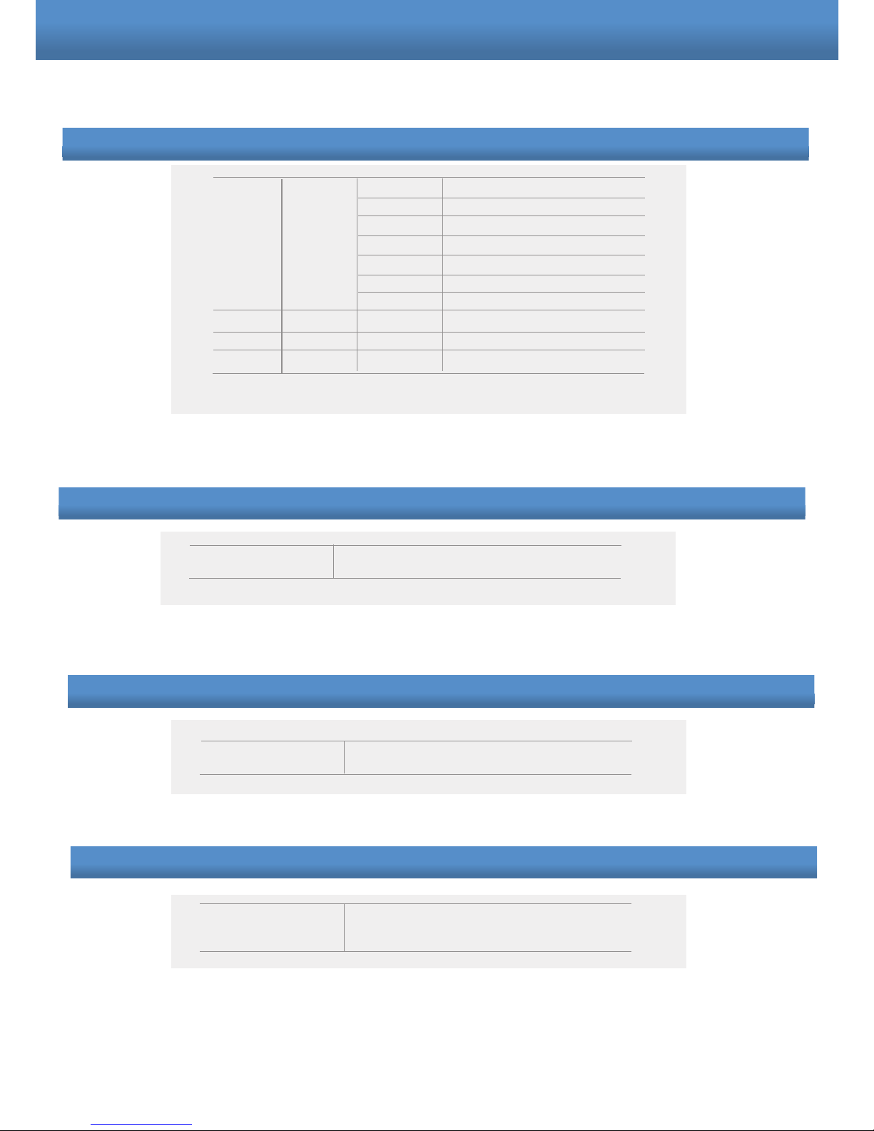
NOISE REDUCTION
NOISE REDUCTION 00~99
SHOW MODE
SHOW MODE WALL 0/ WALL 90/ WALL 180/ WALL
270/ DESK/ CEILING
DAY/NIGHT
DAY/NIGHT AUTO, DAY, NIGHT
MASK
MASK
COLOR
TRANSP
RETURN
MODE
AREA
XPOS
YPOS
WIDTH
HEIGHT
RETURN
1~5
1~3
OFF/ON
1~4
0001~1943
0001~1943
0000~1943
0000~1943
MASK (Privacy Zone)
Page 9
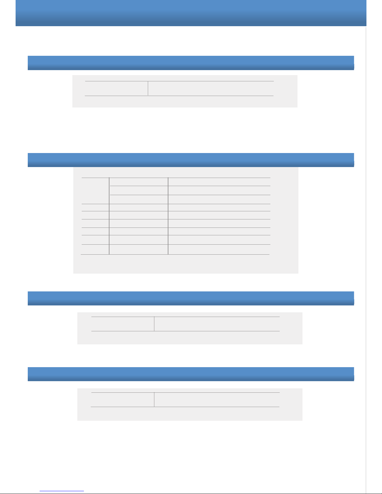
PATTERN (Display Mode Option)
PATTERN MODE 1~13
REBOOT
REBOOT
EXIT
EXIT
SYSTEM CAMERA1
CAMERA2
CAMERA3
CAMERA4
AUTOFLIP
SETID
LOAD DEFAULT
RETURN
ON/OFF
ON/OFF
ON/OFF
ON/OFF
ON/OFF
If user plans to have more than 1
device in the installation
Will reset the device to factory default
SYSTEM
When you change the pattern mode, you have to wait 20 sec
until the change is displayed on the monitor.
Page 10
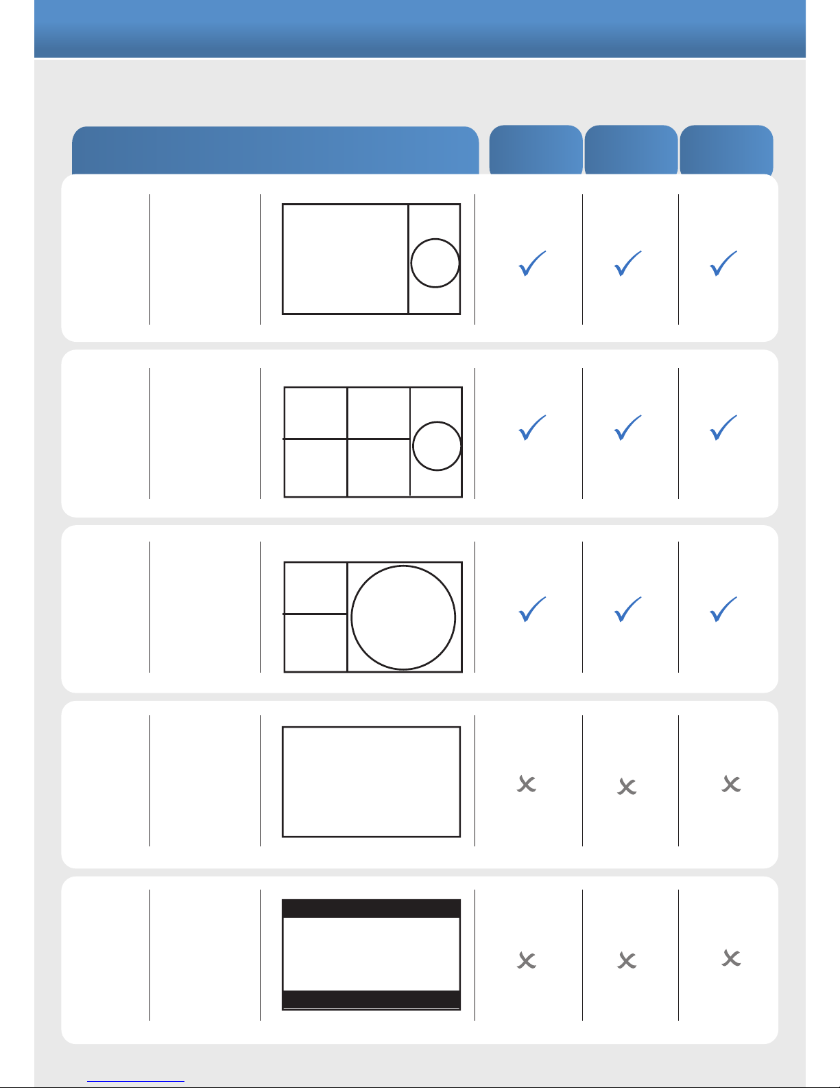
PATTERNS
MODE
1~4
Camera
1~4 + 360º
Camera 1 +
Camera 3 +
360º
*See Note
1
180º in
16:9
Display
Quad +
360º
MODE 5
MODE 6
MODE 7
MODE 8
PATTERN
PRESET
TOUR
PRESET
SEQUENCE
MOTION
TRACKING
CAMERA 1
360º
CAMERA 1 CAMERA 2
CAMERA 3 CAMERA 4
360º
180º IN FULL SCREEN DIS PLAY
CAMERA 1
CAMERA 3
360º
180º IN 16:9 DISPLAY
When you change the pattern mode, you have to wait 20 sec until the change is
displayed on the monitor.
Page 11
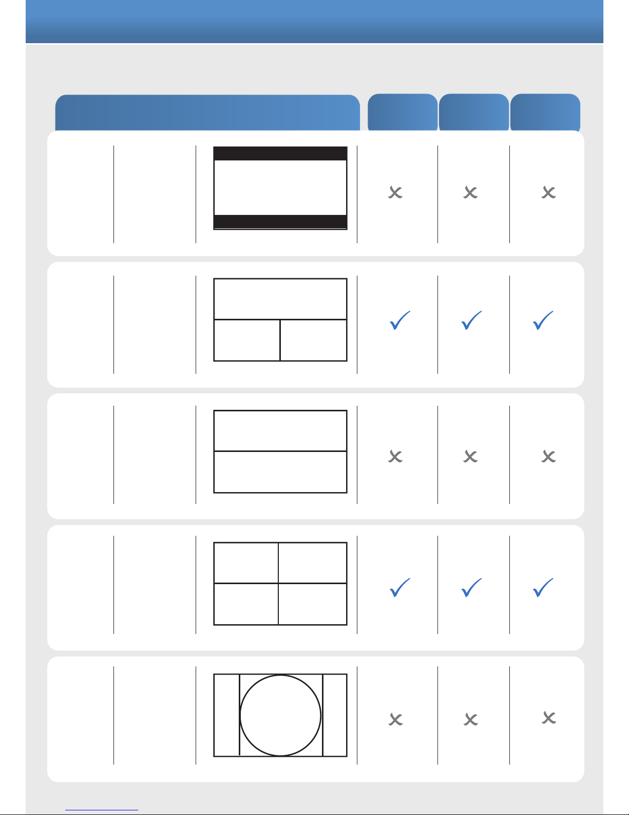
MODE 9 360º Flat
180º + 180º
Quad
Display
Only
360º
Display
Only
180º +
Camera 3 +
Camera 4
MODE 10
MODE 11
MODE 12
MODE 13
PATTERN
PRESET
TOUR
PRESET
SEQUENCE
MOTION
TRACKING
360º FLAT
180º (0 >180º)
180º (181º >360º)
CAMERA 3 CAMERA 4
180º
CAMERA 1
CAMERA 2
CAMERA 3
CAMERA 4
360º
Page 12
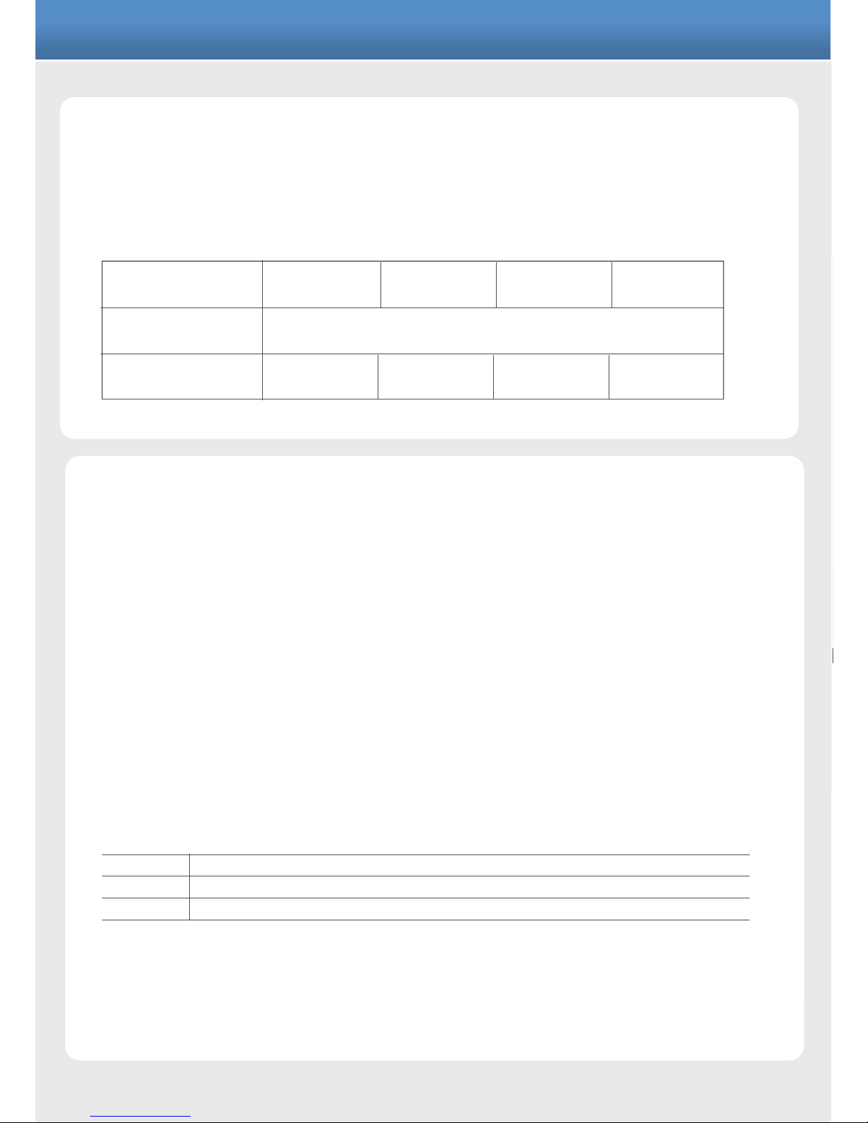
NOTE 1
*Pattern Mode 7
In this mode the user can choose among 4 different angle view, each can have
horizontal and vertical flexibility range
COMMAND LIST
For camera 1 to 4 it is possible to define 3 preset points. These can be use for preset tour
(76) and the preset sequence display (66).
To define a preset for example, preset 1 on camera 1:
Select camera 1
Adjust the camera view using the joystick.
Press "SET" + "1" + "ENTER" on the keyboard (the camera OSD will display POINT1)
Preset set-up may differ depending on RS485 control device.
Concept Pro VA-KBDPRO+ - settings as above. Menu navigation selected by up/down left/right joystick control.
PRESET
NUMBER FUNCTION
95 Enter camera menu
66 Preset Sequence
76 Preset Tour
MOTION DETECTION AND TRACKING
This camera has a motion detection feature and tracks a moving object in the field of view.
Due to the high level of processing for the CPU, it can be activated on one channel only.
It doesn’t apply for 180° and 360° view even if motion detection is enabled.
View available
Verticale range
Horizontal range
120°
-5 > +5
140°
-3 > +3
160°
-1 > +1
180°
0
-5 > +5
Page 13
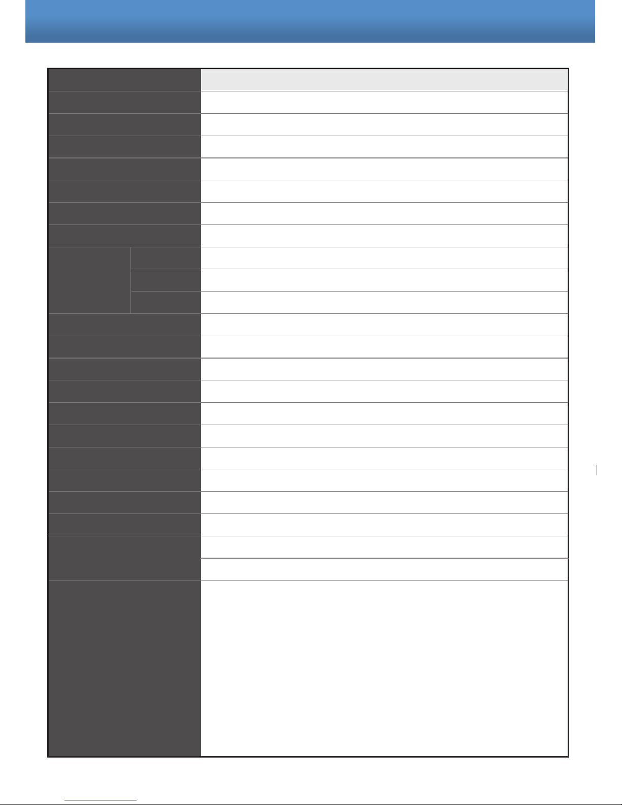
SPECIFICATION
360º Panoramic camera
NTSC or PAL
1/3.2” Color CMOS QSXGA(5Mega Pixel : 2592x1944) image sensor
Internal
2:1 Interlace
More than 51dB
X3; X2; X1; AUTO; 1/100; 1/120; 1/250
Auto
185º
185º
185º
0.45 / 1
PELCO D / 9600
4 CH CVBS / HDMI / SDI
Board lens 1.19mm / F2.0
1080P
DC12V Jack ± 10% / 1A
6.6W (Max)
550mA (Max)
-10°C ~ 50 °C (14°F ~ 122°F )
-20°C ~ 70°C (-4°F ~ 158°F)
78.82(H) x 145(Diameter)mm
78.82(H) x 190(Diameter)mm
Design and specification are subject to change without notice.
Model
Signal System
Pick up device
Synchronizing
Scanning System
S/N Ratio
Electronic Shutter
White Balance
Angle of view Diagonal
Horizontal
Vertical
Gamma Correct
RS485
Video Output
Lens Type
Format
Power Source
Power Consumption
Current
Operating Temperature
Storage Temperature
Dimension
Page 14
 Loading...