

Page 1

EnergySmart
®
Dryer
W Series Models 600 through 5000 with TouchViewTMTechnology (Allen-Bradley)
Corporate Office: 724.584.5500 l Instant Access 24/7 (Parts and Service): 800.458.1960 l Parts and Service: 814.437.6861
U S E R G U I D E
UGD0 41-1212
www.conairgroup.com
Page 2

Conair recommends recording the model and serial number(s) of your equipment
and the date you received it in the User Guide. Our service department uses this
information, along with the manual number, to provide help for the specific equipment you installed.
Please keep this User Guide and all manuals, engineering prints and parts lists
together for documentation of your equipment.
Date:
Manual Number: UGD0041-1212
Serial Number(s):
Model Number(s):
Software Version(s):
Panelview Plus Operator Interface Terminal
Firmware Version Number:
Application File Name:
Programmable Logic Controller:
Firmware Version Number:
Application File Name:
Please record your equipment’s
model and serial number(s) and
the date you received it in the
spaces provided.
DISCLAIMER: Conair shall not be liable for errors contained in this User Guide or for incidental,
consequential damages in connection with the furnishing, performance or use of this information.
Conair makes no warranty of any kind with regard to this information, including, but not limited
to the implied warranties of merchantability and fitness for a particular purpose.
Co p yr ig ht 2 01 2 l C on ai r l A l l ri gh ts r es er ve d
NOTE: The software,
firmware and application
file information for your
specific EnergySmart
Dryer System is contained
on a serial tag that was
attached to the inside of
the EnergySmart Dryer’s
control panel during
assembly.
✐
Page 3

Table of Contents
1-1 Intr odu cti on
Purpose of the user guide . . . . . . . . . . . . . . . . . . . . . . . . . . . . . . . . 1-2
How the guide is organized . . . . . . . . . . . . . . . . . . . . . . . . . . . . . . 1-2
Using the EnergySmart Dryer with your system . . . . . . . . . . . . . . . 1-3
Your responsibilities as a user. . . . . . . . . . . . . . . . . . . . . . . . . . . . . 1-3
ATTENTION: Read this so no one gets hurt . . . . . . . . . . . . . . . . . . . 1-4
How to use the lockout device . . . . . . . . . . . . . . . . . . . . . . . . . . . . 1-6
2-1 Descrip tio n
What is the EnergySmart Dryer System? . . . . . . . . . . . . . . . . . . . . .2-2
Typical applications . . . . . . . . . . . . . . . . . . . . . . . . . . . . . . . . . . . . .2-2
How the EnergySmart Dryer System works . . . . . . . . . . . . . . . . . . .2-3
Specifications: EnergySmart Carousel Plus W Series
Dehumidifying Dryers . . . . . . . . . . . . . . . . . . . . . . . . . . . . . . 2-4
Hopper Temperature Controller (HTC) . . . . . . . . . . . . . . . . . . . . . . . 2-5
GasTrac (CGT) Process Air Heater . . . . . . . . . . . . . . . . . . . . . . . . . . 2-6
Dust Collectors . . . . . . . . . . . . . . . . . . . . . . . . . . . . . . . . . . . . . . . . 2-7
Positive Displacement (PD) Pumps . . . . . . . . . . . . . . . . . . . . . . . . . 2-8
CH Series Insulated Hoppers . . . . . . . . . . . . . . . . . . . . . . . . . . . . . . 2-9
Drying Monitor, DM-II Model . . . . . . . . . . . . . . . . . . . . . . . . . . . . . 2-12
EnergySmart Dryer control options . . . . . . . . . . . . . . . . . . . . . . . . 2-13
3-1 Install a tio n
Installation - General . . . . . . . . . . . . . . . . . . . . . . . . . . . . . . . . . . 3-5
Unpacking the EnergySmart Dryer System components . . . . . . . . . 3-6
Preparing for installation . . . . . . . . . . . . . . . . . . . . . . . . . . . . . . . . . 3-7
Ta bl e of Con te n ts l i
Page 4

Positioning the CH hopper floor stand . . . . . . . . . . . . . . . . . . . . . . . 3-8
Installation of the HTC control
(Models HTC 30, 60 and 90) . . . . . . . . . . . . . . . . . . . . . . . . . 3-9
(Models HTC 120) . . . . . . . . . . . . . . . . . . . . . . . . . . . . . . . . 3-10
(Models HTC 180 and 270) . . . . . . . . . . . . . . . . . . . . . . . . . 3-10
Location and mounting of the HTC heater assembly
(Models HTC 30, 60 and 90) . . . . . . . . . . . . . . . . . . . . . . . . 3-11
(Models HTC 120) . . . . . . . . . . . . . . . . . . . . . . . . . . . . . . . . 3-11
(Models HTC 180 and 270) . . . . . . . . . . . . . . . . . . . . . . . . . 3-11
Installing the CH hopper cone section . . . . . . . . . . . . . . . . . . . . . . 3-12
Installing the CH hopper door, upper and lid sections . . . . . . . . . . 3-13
Installing the cyclone (optional) . . . . . . . . . . . . . . . . . . . . . . . . . . . 3-17
Installing the drying monitor probe . . . . . . . . . . . . . . . . . . . . . . . . 3-22
Installing the receiver(s) (optional). . . . . . . . . . . . . . . . . . . . . . . . . 2-25
Installing the purge valve(s) (optional) . . . . . . . . . . . . . . . . . . . . . . 3-25
Installing the modular distribution box(es) (optional) . . . . . . . . . . . 3-25
Securing the CH hopper to the floor . . . . . . . . . . . . . . . . . . . . . . . 3-26
Location and mounting of the GasTrac heater . . . . . . . . . . . . . . . . 3-27
Location and mounting of the dust collector (optional) . . . . . . . . . 3-28
Location and mounting of the vacuum pump(s)
and dust collector(s) (optional) . . . . . . . . . . . . . . . . . . . . . . 3-30
Positioning the dryer on the floor . . . . . . . . . . . . . . . . . . . . . . . . . 3-31
Removing the cable tie from the desiccant wheel
(W600-1000 models) . . . . . . . . . . . . . . . . . . . . . . . . . . . . . 3-31
Installing the regeneration exhaust cover . . . . . . . . . . . . . . . . . . . 3-31
Installing the return air inlet and air outlet adapters
(W1600-5000 models) . . . . . . . . . . . . . . . . . . . . . . . . . . . . 3-33
Installing the overhead process air duct
(W3200-5000 models) . . . . . . . . . . . . . . . . . . . . . . . . . . . . 3-34
ii l Ta bl e of Co n te nt s
Page 5

Installation - Piping/Hoses. . . . . . . . . . . . . . . . . . . . . . . . . . . . . 3-35
Optional hard piping kits . . . . . . . . . . . . . . . . . . . . . . . . . . . . . . . . 3-36
Connecting the heat sources. . . . . . . . . . . . . . . . . . . . . . . . . . . . . 3-37
Hopper Temperature Controller (HTC) as heat source . . . . . 3-37
GasTrac as heat source. . . . . . . . . . . . . . . . . . . . . . . . . . . . 3-38
Connecting the dryer to the heat source . . . . . . . . . . . . . . . . . . . . 3-39
Connecting the dust collector (optional). . . . . . . . . . . . . . . . . . . . . 3-40
Connecting the cyclone separator (optional) . . . . . . . . . . . . . . . . . 3-41
Installing the Dwyer 641 air velocity transmitter . . . . . . . . . . . . . . 3-42
Installing the level switch (optional). . . . . . . . . . . . . . . . . . . . . . . . 3-44
Adjusting the level sensor (optional) . . . . . . . . . . . . . . . . . . . . . . . 3-45
Installing the process protection RTD sensor. . . . . . . . . . . . . . . . . 3-46
Location of the process material temperature probe (RTD) . . . . . . 3-47
Installing the GasTrac RTD sensor . . . . . . . . . . . . . . . . . . . . . . . . . 3-48
Installing the return air dew point line. . . . . . . . . . . . . . . . . . . . . . 3-49
Installation - Main Power Connections . . . . . . . . . . . . . . . . . . . 3-51
Connecting main power to the dryer . . . . . . . . . . . . . . . . . . . . . . . 3-52
Connecting main power to the HTC
(Models HTC 30, 60, 90 and 120) . . . . . . . . . . . . . . . . . . . . 3-53
(Models HTC 180 and 270) . . . . . . . . . . . . . . . . . . . . . . . . . 3-54
Connecting main power to the GasTrac. . . . . . . . . . . . . . . . . . . . . 3-56
Connecting main power to the vacuum pump(s) (optional) . . . . . . 3-57
Connecting main power to the dust collector(s) (optional) . . . . . . . 3-57
Installation - Conveying Lines . . . . . . . . . . . . . . . . . . . . . . . . . . 3-59
Connecting the conveying lines to the receiver(s) (optional). . . . . . 3-60
Connecting the conveying lines to the purge valve(s) (optional) . . . 3-60
Connecting the conveying lines to the vacuum pump(s) and
dust collector(s) (optional) . . . . . . . . . . . . . . . . . . . . . . . . . . 3-61
Installation - Water Lines . . . . . . . . . . . . . . . . . . . . . . . . . . . . . . 3-63
Typical water lines installation drawing. . . . . . . . . . . . . . . . . . . . . 3-64
Ta bl e of Con te n ts l iii
Page 6

Connecting the aftercooler/intercooler and optional
precooler (W600-1000) . . . . . . . . . . . . . . . . . . . . . . . . . . . . 3-65
Connecting the aftercooler/intercooler and optional
precooler (W1600-5000) . . . . . . . . . . . . . . . . . . . . . . . . . . . 3-66
Installation - Control and Communications Wiring. . . . . . . . . . 3-67
Connecting the HTC to the HTC controller . . . . . . . . . . . . . . . . . . . 3-68
Connecting the RTD sensors (HTC only) . . . . . . . . . . . . . . . . . . . . 3-70
Connecting the GasTrac RTD sensors . . . . . . . . . . . . . . . . . . . . . . 3-72
Connecting the drying monitor probe to the dryer . . . . . . . . . . . . . 3-73
Connecting the receiver to the level switch (optional) . . . . . . . . . . 3-74
Connecting the EnergySmart Dryer control to system
components . . . . . . . . . . . . . . . . . . . . . . . . . . . . . . . . . . . . 3-75
Installation - Compressed Air Lines . . . . . . . . . . . . . . . . . . . . . 3-85
Connecting the compressed air lines (optional) . . . . . . . . . . . . . . . 3-86
Installation - Gas Piping and Exhaust Flue . . . . . . . . . . . . . . . . 3-87
Typical gas line installation drawing . . . . . . . . . . . . . . . . . . . . . . . 3-88
Installing the Conair GasTrac. . . . . . . . . . . . . . . . . . . . . . . . . . . . . 3-89
Connecting the gas and the exhaust flue to the GasTrac. . . . . . . . 3-92
Installation - Testing. . . . . . . . . . . . . . . . . . . . . . . . . . . . . . . . . . 3-95
Checking for proper air flow . . . . . . . . . . . . . . . . . . . . . . . . . . . . . 3-96
Testing the variable frequency drive (VFD). . . . . . . . . . . . . . . . . . . 3-99
Testing the installation of the HTC. . . . . . . . . . . . . . . . . . . . . . . . 3-100
Checking the gas and electrical systems of the GasTrac . . . . . . . 3-102
Testing the installation of the GasTrac. . . . . . . . . . . . . . . . . . . . . 3-103
Testing the primary receiver (optional) . . . . . . . . . . . . . . . . . . . . 3-105
Testing the secondary receiver (optional) . . . . . . . . . . . . . . . . . . 3-107
Configuring the Dwyer 641 air velocity transmitter . . . . . . . . . . . 3-109
Configuring the DM-II drying monitor . . . . . . . . . . . . . . . . . . . . . 3-110
Configuring the level switch (optional). . . . . . . . . . . . . . . . . . . . . 3-110
Using communications (optional). . . . . . . . . . . . . . . . . . . . . . . . . 3-113
iv l Ta bl e of Co n te nt s
Page 7

4-1 Op era tio n
The EnergySmart Dryer System control panel . . . . . . . . . . . . . . . . . 4-2
How to navigate the control screens . . . . . . . . . . . . . . . . . . . . . . . . 4-3
Control function flow charts . . . . . . . . . . . . . . . . . . . . . . . . . . . . . . 4-6
Login flow chart . . . . . . . . . . . . . . . . . . . . . . . . . . . . . . . . . . 4-6
Operation flow chart 1 . . . . . . . . . . . . . . . . . . . . . . . . . . . . . 4-7
Operation flow chart 2 . . . . . . . . . . . . . . . . . . . . . . . . . . . . . 4-8
Operation flow chart 3 . . . . . . . . . . . . . . . . . . . . . . . . . . . . . 4-9
Setup flow chart 1 . . . . . . . . . . . . . . . . . . . . . . . . . . . . . . . 4-10
Equipment setup flow chart 1 . . . . . . . . . . . . . . . . . . . . . . . 4-11
Equipment setup flow chart 2 . . . . . . . . . . . . . . . . . . . . . . . 4-12
Communications setup flow chart . . . . . . . . . . . . . . . . . . . . 4-13
Example setpoint change . . . . . . . . . . . . . . . . . . . . . . . . . . 4-14
Control function descriptions. . . . . . . . . . . . . . . . . . . . . . . . . . . . . 4-15
EnergySmart Dryer System security levels . . . . . . . . . . . . . . . . . . 4-54
EnergySmart Dryer System Modbus communications . . . . . . . . . . 4-56
Starting the EnergySmart Dryer System
(Without OptiMizer™ mode) . . . . . . . . . . . . . . . . . . . . . . . . 4-58
Adjusting the EnergySmart Dryer System
(Without OptiMizer™ mode) . . . . . . . . . . . . . . . . . . . . . . . . 4-62
Starting the EnergySmart Dryer System
(With OptiMizer™ mode). . . . . . . . . . . . . . . . . . . . . . . . . . . 4-67
Stopping the EnergySmart Dryer System. . . . . . . . . . . . . . . . . . . . 4-71
Using dryer recipes (optional) . . . . . . . . . . . . . . . . . . . . . . . . . . . . 4-74
Copying files from the EnergySmart Dryer System . . . . . . . . . . . . 4-80
Using Dewpoint. . . . . . . . . . . . . . . . . . . . . . . . . . . . . . . . . . . . . . . 4-84
Using OptiMizer™. . . . . . . . . . . . . . . . . . . . . . . . . . . . . . . . . . . . . 4-85
Ta bl e of Con te n ts l v
Page 8

5-1 Main ten anc e
Preventative maintenance checklist . . . . . . . . . . . . . . . . . . . . . . . . 5-2
Inspecting the hoses, piping and gaskets . . . . . . . . . . . . . . . . . . . . 5-8
Cleaning the CH hopper . . . . . . . . . . . . . . . . . . . . . . . . . . . . . . . . . 5-9
Maintaining the Dwyer 641 air velocity transmitter . . . . . . . . . . . . 5-10
Cleaning the combustion filter of the GasTrac . . . . . . . . . . . . . . . . 5-11
Cleaning the electrical enclosure filter of the GasTrac. . . . . . . . . . 5-12
Replacing the spark igniter of the GasTrac . . . . . . . . . . . . . . . . . . 5-13
Cleaning the ultraviolet flame detector of the GasTrac. . . . . . . . . . 5-15
Cleaning the process filter. . . . . . . . . . . . . . . . . . . . . . . . . . . . . . . 5-17
Cleaning the regeneration filter . . . . . . . . . . . . . . . . . . . . . . . . . . . 5-18
Cleaning the aftercooler/intercooler coils. . . . . . . . . . . . . . . . . . . . 5-19
Cleaning the volatile trap on the demister
(W600-1000). . . . . . . . . . . . . . . . . . . . . . . . . . . . . . . . . . . . 5-21
Cleaning the volatile trap on the demister
(W1600-5000). . . . . . . . . . . . . . . . . . . . . . . . . . . . . . . . . . . 5-22
Cleaning the precooler coils (optional). . . . . . . . . . . . . . . . . . . . . . 5-23
Replacing the regeneration heater
(W600-1000). . . . . . . . . . . . . . . . . . . . . . . . . . . . . . . . . . . . 5-24
(W1600-2400). . . . . . . . . . . . . . . . . . . . . . . . . . . . . . . . . . . 5-26
(W3200-5000). . . . . . . . . . . . . . . . . . . . . . . . . . . . . . . . . . . 5-28
Checking dew point . . . . . . . . . . . . . . . . . . . . . . . . . . . . . . . . . . . 5-30
Cleaning the dust collector (optional). . . . . . . . . . . . . . . . . . . . . . . 5-32
Cleaning the cyclone separator (optional) . . . . . . . . . . . . . . . . . . . 5-32
6-1 Troub les hoo tin g
Before beginning. . . . . . . . . . . . . . . . . . . . . . . . . . . . . . . . . . . . . . . 6-2
A few words of caution . . . . . . . . . . . . . . . . . . . . . . . . . . . . . . . . . 6-3
vi l Ta bl e of Co n te nt s
Page 9

DIAGNOSTICS
How to identify the cause of a problem . . . . . . . . . . . . . . . . . . . . . 6-4
Shutdown alarms . . . . . . . . . . . . . . . . . . . . . . . . . . . . . . . . . . . . . 6-7
Passive alarms . . . . . . . . . . . . . . . . . . . . . . . . . . . . . . . . . . . . . . 6-14
Dew point troubleshooting. . . . . . . . . . . . . . . . . . . . . . . . . . . . . . . 6-28
Poor material drying troubleshooting. . . . . . . . . . . . . . . . . . . . . . . 6-29
REPAIR
Replacing fuses. . . . . . . . . . . . . . . . . . . . . . . . . . . . . . . . . . . . . . . 6-34
Checking heater solid state relays. . . . . . . . . . . . . . . . . . . . . . . . . 6-35
Checking or replacing temperature sensors . . . . . . . . . . . . . . . . . 6-36
Replacing the desiccant wheel assembly (W600-1000). . . . . . . . . 6-37
Replacing the desiccant wheel motor (W600-1000) . . . . . . . . . . . 6-39
Replacing the desiccant wheel motor (W600-1000) . . . . . . . . . . . 6-40
A Ap pen dix
We’re here to help . . . . . . . . . . . . . . . . . . . . . . . . . . . . . . . . . . . . . A-1
How to contact customer service . . . . . . . . . . . . . . . . . . . . . . . . . . A-1
Before you call... . . . . . . . . . . . . . . . . . . . . . . . . . . . . . . . . . . . . . . A-1
Equipment guarantee . . . . . . . . . . . . . . . . . . . . . . . . . . . . . . . . . . A-2
Performance warranty . . . . . . . . . . . . . . . . . . . . . . . . . . . . . . . . . . A-2
Warranty limitations . . . . . . . . . . . . . . . . . . . . . . . . . . . . . . . . . . . . A-2
Conair print numbers list . . . . . . . . . . . . . . . . . . . . . . . . . . . . . . . . A-3
Ta bl e of Con te n ts l vii
Page 10

vi i i l Ta bl e of C on te nt s
Page 11

Introduction
Purpos e of the user guide . . . . . . . . . . . . . . 1- 2
How the guide is o rganiz e d . . . . . . . . . . . . . 1 - 2
Using the Energ y S mart Dry e r
with your system . . . . . . . . . . . . . . . . . 1- 3
Yo u r r e s ponsib i l i ties as a us e r . . . . . . . . . . . 1-3
ATTENT I O N:
Read this so n o o n e ge t s hu r t . . . . . . . . 1-4
How to u se t h e l o c kout device . . . . . . . . . . . 1-6
S E C T I O N
1
In t ro du ct io n l 1 -1
1
In t rod u ctio n
Page 12

✐
Purpose of the User Guide
This User Guide describes the Conair EnergySmart®Dryer System with
TouchViewTMTechnology and explains step-by-step how to install, operate, maintain and repair this equipment.
Before installing this product, please take a few moments to read the User
Guide and review the diagrams and safety information in the instruction
packet. You also should review manuals covering associated equipment in
your system. This review won’t take long, and it could save you valuable
installation and operating time later.
How the Guide is Organized
Symbols have been used to help organize the User Guide and call your
attention to important information regarding safe installation and operation.
Symbols within triangles warn of conditions that could be hazardous to users or
could damage equipment. Read and take precautions before proceeding.
Numbers indicate tasks or steps to be performed by the user.
A diamond indicates the equipment’s response to an action performed by the user.
An open box marks items in a checklist.
A circle marks items in a list.
Indicates a tip. A tip is used to provide you with a suggestion that will help you with
the maintenance and the operation of this equipment.
Indicates a note. A note is used to provide additional information about the steps
you are following throughout the manual.
1
◆
❒
•
✒
1- 2 l Int ro d uc ti on
Page 13

In t ro du ct io n l 1 -3
Using the EnergySmart Dryer with
Your System
The Conair EnergySmart®Dryer with TouchViewTMTechnology used within your
system is factory configured to be used as a central dryer only. Therefore, this
manual incorporates the information necessary to use these dryers for central
drying applications.
Your Responsibility as a User
You must be familiar with all safety procedures concerning installation, operation and maintenance of this equipment. Responsible safety procedures include:
• Thorough review of this User Guide, paying particular attention
to hazard warnings, appendices and related diagrams.
• Thorough review of the equipment itself, with careful attention
to voltage sources, intended use and warning labels.
• Thorough review of instruction manuals for associated equipment.
• Step-by-step adherence to instructions outlined in this User Guide.
1
In t rod u ctio n
NOTE: Dryers can be used for
various applications.
✐
Page 14

1- 4 l Int ro d uc ti on
ATTENTION:
Read this so no one gets h urt
We design equipment with the user’s safety in mind. You can avoid the potential
hazards identified within this system by following the procedures outlined below
and elsewhere in the User Guide.
WA RNING: Impro p e r i n s tallati o n , operat i o n o r
serv i c ing m ay r e sult in e quipmen t dam a g e o r
persona l inj u r y.
This equipment should be installed, adjusted and serviced by qualified
technicians who are familiar with the construction, operation and
potential hazards of this type of machinery.
All wiring, disconnects and fuses should be installed by qualified electrical technicians in accordance with electrical codes in your region.
Always maintain a safe ground. Do not operate the equipment at power
levels other than what is specified on the machine serial tag and data
plate.
WA RNING: Vo ltage hazard
This equipment is powered by three-phase alternating current,
as specified on the equipment’s serial tags and data plates. Reference
optional additional equipment’s manuals for their power requirements.
A properly-sized conductive ground wire from the incoming power
supply must be connected to the chassis ground terminal inside the
electrical enclosure. Improper grounding can result in severe personal
injury and erratic machine operation.
Always disconnect and lock out the incoming main power source before
opening the electrical enclosure or performing non-standard operating
procedures, such as routine maintenance. Only qualified personnel
should perform troubleshooting procedures that require access to the
electrical enclosure while power is on.
(continued)
Page 15

1
In t rod u ctio n
In t ro du ct io n l 1 -5
ATTENTION:
Read this so no one gets h urt
(c on ti nu ed )
We design equipment with the user’s safety in mind. You can avoid the potential
hazards identified within this system by following the procedures outlined below
and elsewhere in the User Guide.
CA UTION: Hot Surfaces.
Always protect yourself from hot surfaces inside the dryer and hopper.
Also exercise caution around exterior surfaces that may become hot
during use. These include the hopper door frame, the exterior of an
uninsulated hopper, the return air hose and the dryer’s process filter
housing and exhaust outlet and the Hopper Temperature Controller
(HTC) or GasTrac Dryer (CGT).
WA RNING: Do not p lace aerosol , c o mpresse d
gas o r f l a mmable mater i als o n o r nea r thi s
equipme n t .
The hot temperatures associated with the drying process may cause
aerosols or other flammable materials placed on the dryer or hopper to
explode.
Page 16
1- 6 l Int ro d uc ti on
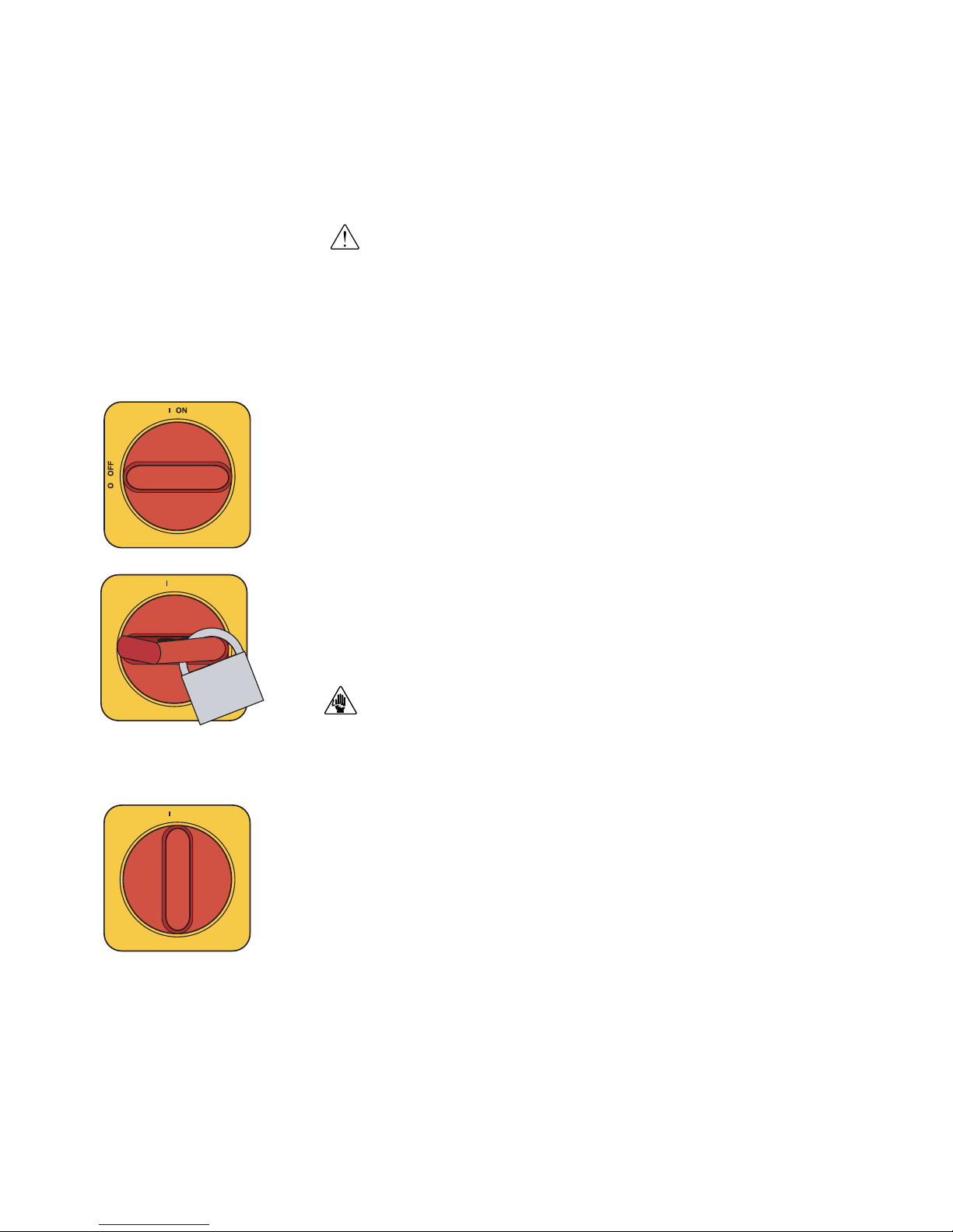
How to Use the Lockout Device
CAUTION: Before performing maintenance or repairs on this product, you should
disconnect and lockout electrical power sources to prevent injury from unexpected
energization or start-up. A lockable device has been provided to isolate this
product from potentially hazardous electricity.
Lockout is the preferred method of isolating machines or equipment from energy
sources. Your Conair product is equipped with the lockout device pictured below.
To use the lockout device:
1
Stop or turn off the equipment.
2
Isolate the equipment from the electric power. Turn the rotary
disconnect switch to the OFF, or “O” position.
3
Secure the device with an assigned lock or tag. Insert a lock or tag
in the holes to prevent movement.
4
The equipment is now locked out.
WARNING: Before removing lockout devices and returning switches to the ON
position, make sure that all personnel are clear of the machine, tools have been
removed and all safety guards reinstalled.
To restore power, turn the rotary disconnect back to the ON position:
1
Remove the lock or tag.
2
Turn the rotary disconnect switch to the ON or “I” position.
ON
O OFF
ON
O OFF
Page 17

De s cr ip ti on l 2- 1
Description
What is the E nergy S m art D rye r Sys t e m ? . . . . 2-2
Typica l a p p l icat i o n s . . . . . . . . . . . . . . . . . . 2- 2
How the Energ y S mart Drye r Sy s t e m w o r ks . . . 2-3
Specif i c a tion s : E n ergyS m a rt C a rousel
Plus W Series Dehu m i d ifying Dr y ers . . . . 2-4
Hopper Temp e r a ture Cont r o l ler ( HTC) . . . 2-5
GasTrac (CGT) Proce s s A ir H e ater . . . . . . 2-6
Dust Collec t o r s . . . . . . . . . . . . . . . . . . 2- 7
Po sitive Displ a c ement (PD) Pumps . . . . . 2-8
CH S e ries Insula t ed H o ppers . . . . . . . . . 2 - 9
Dry i n g M o n i tor, DM-II Mode l . . . . . . . . 2-1 2
Energ y S mart Dry e r co n t r ol o p tions . . . . 2-13
S E C T I O N
2
2
De s cri p tion
Page 18

2- 2 l Des cr i pt io n
What is the EnergySmart®Dryer
System?
Energy efficient drying and superior end product are the results of having precise
control of your drying process. The EnergySmart Dryer System control allows
you to optimize your system settings to achieve consistent drying results that boost
your plant-wide efficiency and produce high quality final product. An OptiMizer™
Mode automatically adjusts the air flow and temperature of your process for maximum system efficiency.
The EnergySmart Dryer System could include:
• EnergySmart Dryer with TouchViewTMTechnology (Allen-Bradley control)
• CH Hopper with an integrated cyclone - optional
• Heater (gas or electric)
• Dust collector(s) - optional
• Patented DM-II drying monitor technology
• Receiver(s) - optional
• Vacuum pump(s) - optional
• Audible alarm
Typical Applications
1 Dryer on the floor, a single CH Hopper with a Hopper Temperature Controller
(HTC) or GasTrac Dryer (CGT) package on a floor stand.
The EnergySmart Dryer System can be used successfully in applications that
require:
• A contamination-free drying environment
• A constant flow of dehumidified air
• Throughput rates of 400 to 5,000 lbs {181 to 2,268 kg} per hour (some
materials can be run at higher rates).
• Dew points of -40°F {-40°C}.
NOTE: The EnergySmart
®
W600 - 5000 dryer provides
no heat to the process air. A
separate heat source is
required at the hopper inlet to
heat the air to the required
drying temperature.
✐
Page 19
De s cr ip ti on l 2- 3
2
De s cri p tion
How the EnergySmart Dr yer System
Works
The drying circuit is a traditional desiccant drying system. The dryer supplies low
dew point air that has passed through a heater (HTC or GasTrac) into the bottom
of a CH Hopper. The air moves up through the hopper picking up moisture from
the material as it transfers its heat into the material. Once the air is at the top of the
hopper, it returns to the dryer after passing through optional filtration to remove
fines. Once in the dryer, the air is cooled by passing through a cooling coil to
lower the temperature so that the air can be dried as it passes through the desiccant
where the moisture is absorbed.
Page 20
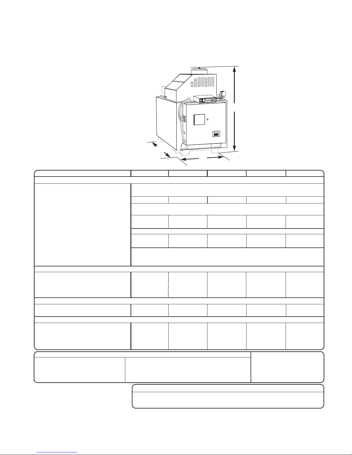
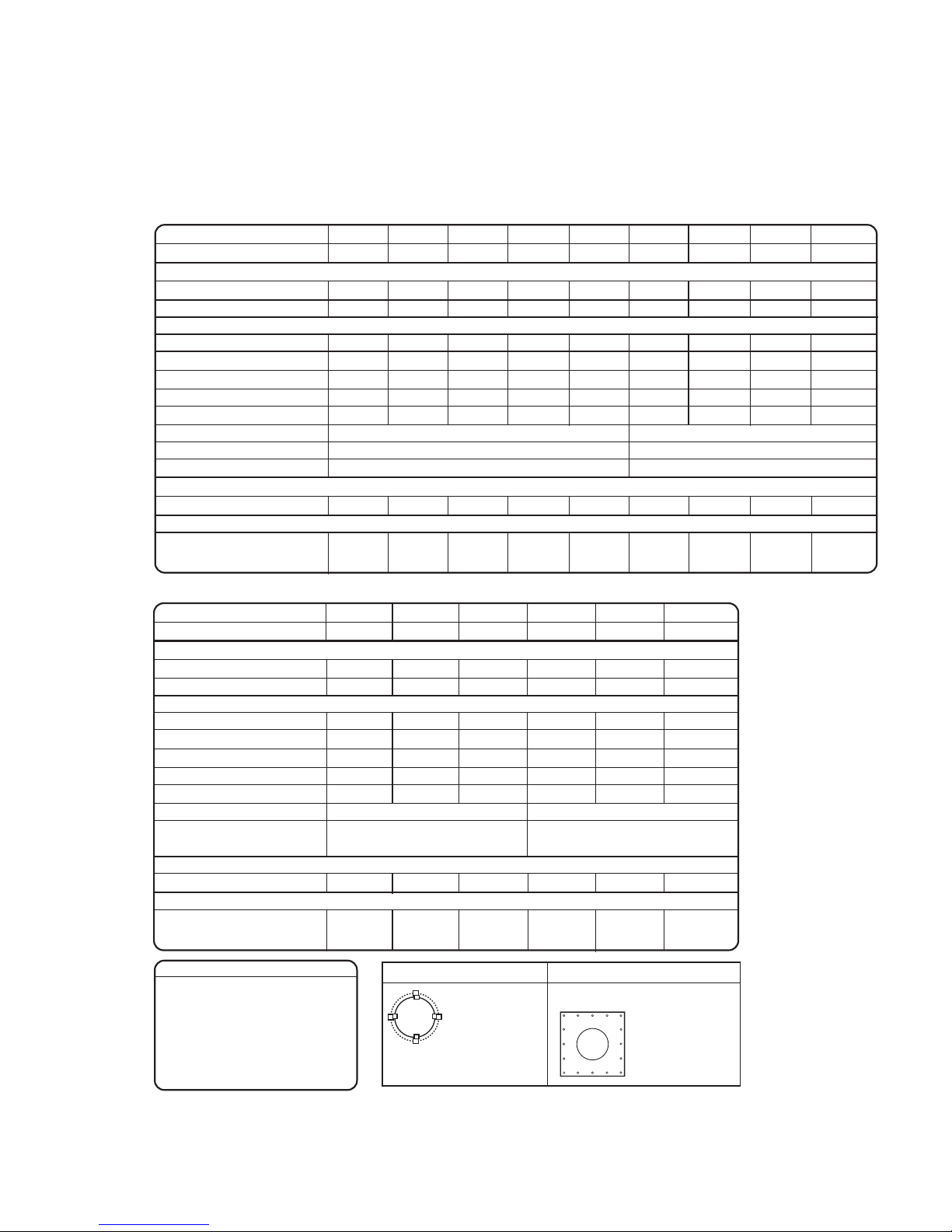
Specifications: EnergySmart Carousel
Plus W Series Dehumidifying Dryers
2- 4 l Des cr i pt io n
TPDX019-0712
SPECIFICATION NOTES:
*
Dryers W600-W5000 that are central dryers do not have process heaters. Hopper Temperature Controllers (HTC’s) or GasTrac Dryers (CGT’s) are used at the hopper for heating the process air. See the Hopper Temperature Controller (HTC) and GasTrac Dryer (CGT) specification sheets for further technical information.
†
Total amps listed apply to dryer only, see the Hopper Temperature Controller (HTC) or GasTrac (CGT) specification sheets for additional power requirements.
‡
Dryers running at 50 Hz will have 17% less airflow, and a 17% reduction in material throughput.
§
Total kW listed at a regeneration temperature of 350°F {177°C}. The total kW listed reflects the kW of the dryer only. It does not include any external heat source, for example
the Hopper Temperature Controller (HTC) or Gastrac Dryer (CGT).
** When drying below 150°F {66°C} a precooler is required.
††
Temperatures above or below the recommended levels may affect dryer performance. Tower, chiller or municipal water sources can be used.
‡‡
Not available in Allen Bradley models.
Specifications may change without notice. Consult a Conair sales representative for the most current information.
APPLICATION NOTES:
All dryers are supplied with an aftercooler/intercooler as standard. The aftercooler/intercooler reduces the temperature of the return air from the drying hopper, improving the efficiency of the desiccant. The
aftercooler/intercooler must be connected with the proper water flow rate and temperature to attain the rated
throughput.
When to use central models
Models W600 - W5000 of Carousel Plus dryers are all configured as central dryers. Central dryers do not
have process heaters. These models should be used when drying multiple materials that require different
drying temperatures. Central models dehumidify the process air, which is then heated to the correct setpoint by a Hopper Temperature Controller (HTC) or GasTrac Dryer (CGT).
When to use additional filtration
The standard return air cartridge filter is sized for the airflow of each dryer model and is suited for most
applications. You should consider adding an optional dust collector and/or volatile trap if:
●
The material contains excessive fines. An additional dust collector or cyclone will extend time between filter
cleaning.
●
The material produces volatiles during drying which condense into a waxy or oily residue. A volatile trap will
help to protect the desiccant.
MODELS W600
*
W800
*
W1000
*
W1300
*
W1600
*
W2000
*
W2400
*
W3200
*
W4000
*
W5000
*
Performance characteristics (with full hopper)
Drying temperature All models 100°- 375°F {38°- 191°C} with options
Dew point All models -40°F {-40°C}
Dimensions inches {cm}
A - Height 93.8 {238.3} 92.2 {134.2} 98.3 {249.7}
B - Width 49.3 {125.2} 53.9 {136.9} 58.2 {147.8}
C - Depth 72.4 {183.9} 106.6 {270.8} 123.6 {313.9}
Outlet/inlet hose diameter 8.0 {20.3} 12.0 {30.5} 12.0 {30.5}
Approximate weight lbs {kg}
Installed 1300 {590} 1300 {590} 1400 {636} 1600 {726} 2000 {907}
Shipping 1495 {678} 1495 {678} 1515 {687} 2620 {1188} 3385 {1535}
Voltage -
Standard/Central
Full load amps
†
400 V/3 phase/50 Hz
‡
89.2 / 34.3 89.2 / 34.3 116.6 / 34.2 152.7 / 42.9 159.4 / 49.6 194.1 / 56.8 221.7 / 57.0 282.7 / 90.5 317.0 / 97.7 371.9 / 97.4
460 V/3 phase/60 Hz 77.6 / 29.8 77.6 / 29.8 101.5 / 29.8 133.4 / 37.8 138.6 / 43.0 168.9 / 49.4 192.8 / 49.4 247.3 / 80.0 275.9 / 84.7 323.7 / 84.7
575 V/3 phase/60 Hz 62.1 / 23.9 62.1 / 23.9 81.1 / 23.8 106.6 / 30.2 110.8 / 34.4 135.1 /39.6 154.2 / 39.6 197.7 / 64.0 220.6 / 67.8 258.7 / 67.7
380 V/3 phase/60 Hz
‡‡
93.9 / 36.1 93.9 / 36.1 122.7 / 36.0 160.7 / 45.2 167.8 / 52.2 204.3 / 59.8 233.4 / 60.0 297.6 / 95.3 333.7 / 102.8 391.5 / 102.5
Total kilowatts§kW {BTU/min} 53 {3017} / 53 {3017} / 72 {4098} / 95 {5407} / 95 {5407} / 114 {6489} / 133 {7570} / 152 {8652} / 190 {10809} / 228 {12972} /
15 {854} 15 {854} 15 {584} 19 {1081} 19 {1081} 19 {1081} 19 {1081} 38 {2157} 38 {2157} 38 {2157}
Water requirements {for aftercooler/intercooler or optional precooler}
**
Recommended temperature
††
45°- 85°F {7° - 29°C} 45°- 85°F {7° - 29°C} 45°- 85°F {7° - 29°C}
Water flow gal./min. {liters/min.} 6 - 25 {22.7 - 94.6} 12 - 40 {45.4 - 151.4} 15 - 50 {56.8 - 189.3}
Water connections NPT 1 1/2 inch NPT 1 1/2 inch NPT 1 1/2 inch NPT
Page 21
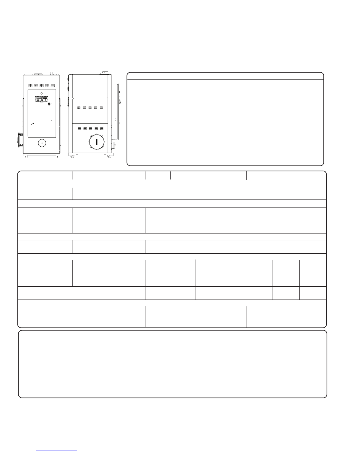
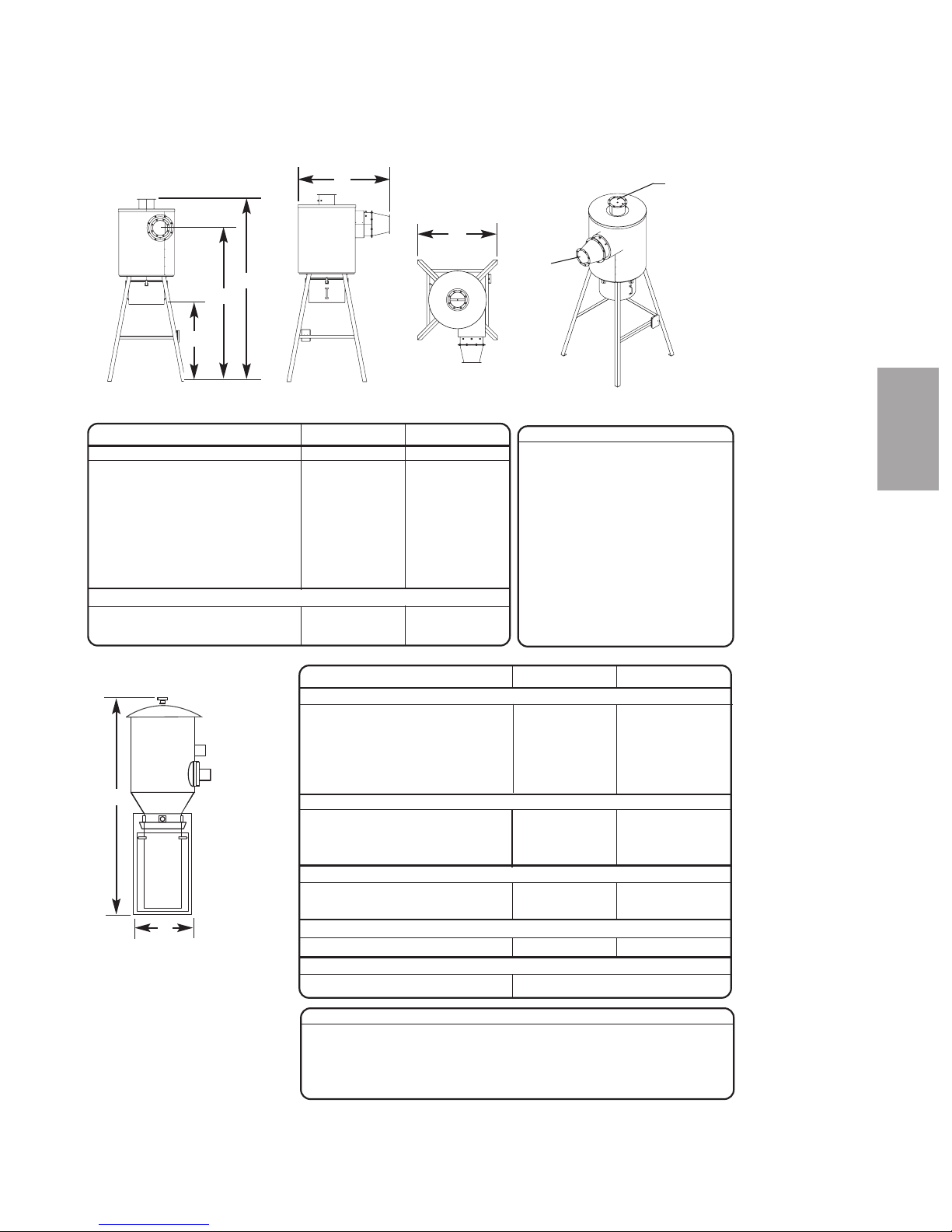
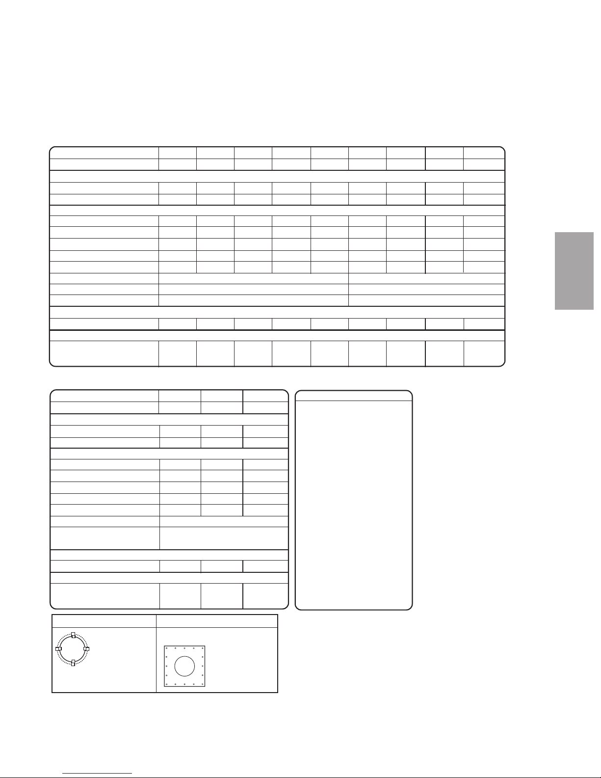
Specifications: Hopper Temper ature
Controller (HTC)
A
B
D
E
F
G
I
MODEL HTC HTC-30H* HTC-60H* HTC-90H* HTC-120H* HTC-180H* HTC-270H*
Carousel Plus dryer model W600 W800 W1000 W1600 W2400 W3200 W5000
Performance characteristics
Temperature range 150° - 375° F {66° - 191° C}
Flow rate cfm 300 400 500 800 1200 1600 2500
Pressure drop@flow rate
inches WC
†
3.0 1.8 2.3 4.0 3.8 5.9 6.4
{mm} WC
†
{76.2} {45.7} {58.4} {101.6} {96.5} {149.9} {162.6}
Dimensions inches {cm} and weight lb {kg}
Heater box dimensions
Inlet size (OD) 8812 12 12 12
Outlet size selection (OD) 8812 12 12 12
A - Height 31.4 {79.8} 27.5 {69.9} 27.0 {68.6} 31.0 {78.7} 34.0 {86.4} 36.4 {92.5}
B - Width 10.1 {25.7} 13.6 {34.5} 16.0 {40.6} 16.0 {40.6} 18.0 {45.7} 24.2 {61.5}
C - Depth 10.7 {27.2} 10.9 {27.7} 10.9 {27.7} 16.0 {40.6} 17.0 {43.2} 17.0 {43.2}
D - Height of discharge 1.75 1.5 2.0 1.0 2.0 1.0
nozzle above the heater box {4.4} {3.8} {5.1} {2.5} {5.1} {2.5}
E - Height of inlet nozzle 10.6 7.1 8.0 10.0 13.0 15.4
below the heater box {26.9} {18.0} {20.3} {25.4} {33.0} {39.1}
Installed weight lb {kg}
‡
38 {17} 37 {17} 78 {35} 93 {43} 102 {46} 131 {59}
Control center dimensions
Height - F 24.0 {61.0} 24.0 {61.0} 36.0 {91.4} 48.0 {122.0} 60.0 {152.4} 60.0 {152.4}
Width - G 24.0 {61.0} 24.0 {61.0} 30.0 {76.2} 36.0 {91.4} 42.0 {106.7} 42.0 {106.7}
Depth - H 10.0 {25.4} 10.0 {25.4} 10.0 {25.4} 10.0 {25.4} 12.0 {30.5} 12.0 {30.5}
Clearance for heat sink - I 3.0 {7.6} 3.0 {7.6} 3.0 {7.6} 3.0 {7.6} 3.0 {7.6} 3.0 {7.6}
Installed weight lb {kg} 150.0 {68.0} 150.0 {68.0} 180.0 {81.6} 250.0 {113.0} consult Conair consult Conair
Voltage full load amps
400 V/3 phase/50-60 Hz 44 87 131 175 261 381
480 V/3 phase/50-60 Hz 38 76 114 152 227 340
575 V/3 phase/50-60 Hz 30 61 91 122 182 272
SPECIFICATION NOTES:
* The HTC model number reflects the kilowatts of each unit. For example, HTC-60 has a 60 kilowatt heater.
† The unit of measure WC is water column.
‡
Weights are approximate.
Specifications may change without notice. Consult a Conair representative for the most current information.
TPDS022-0808
C
De s cr ip ti on l 2- 5
2
De s cri p tion
H
Page 22
MODELS CGT150 CGT250 CGT350 CGT500 CGT700
Performance characteristics
Temperature range ºF {ºC} 250 - 350 {122 - 177}
Maximum flue temperature ºF {ºC} 750 {399}
Combustion blower 0.5 Hp peripheral 0.5 Hp peripheral 1 Hp peripheral 1 Hp peripheral 1 Hp peripheral
Ignition source Spark igniter, interrupted
Burner type Metal-ceramic
Minimum burner capacity BTU/hr 40,000 75,000 90,000 125,000 150,000
Maximum burner capacity BTU/hr 150,000 225,000 350,000 500,000 700,000
Gas consumption*
CFH @250ºF {L/hour} 50 {1416} 90 {2549} 105 {2973} 150 {4248} 230 {6513}
CFH @350ºF {L/hour} 140 {3964} 215 {6088} 325 {9203} 465 {13167} 675 {19114}
Gas pressure to regulator In. H2O {kPa} 10 - 20 {2.49 - 4.98}
Gas pressure from regulator In. H2O {kPa} 4 - 7 {0.99 - 1.74}
Gas heating rate BTU/ft
3
1000
Dimensions in. {mm}
A - Height 54 {1372} 61{1549} 61 {1549} 61 {1549} 61 {1549}
B - Width 29 {737} 37 {940} 37 {940} 37 {940} 37 {940}
C - Length 66 {1676} 64 {1626} 74 {1880} 74 {1880} 74 {1880}
Air inlet/outlet, OD 8 {203} 8 {203} 8 {203} 8 {203} 12 {300}
Approximate weight lb {kg}
Installed 600 {272} 600 {272} 600 {272} 600 {272} 600 {272}
Shipping 700 {317} 700 {317} 700 {317} 700 {317} 600 {272}
Voltage Total amps
380V/3 phase/50Hz 3.0 3.0 1.6 1.3 3.0
415V/3 phase/50Hz 3.0 2.7 1.5 1.2 3.0
240V/3 phase/60Hz 3.0 4.8 2.5 2.0 3.0
480V/3 phase/60Hz 3.0 2.4 1.3 1.0 3.0
Emissions
<10 ppm corrected to 3% O
2
<20 ppm corrected to 3% O
2
<10 ppm corrected to 3% O
2
Carbon Monoxide (CO)
NOX
Unburned hydrocarbons
10 - 30%
2 - 5%
9 - 10.5%
Primary excess air
Oxygen (O2) (ideal 3 - 4%)
Carbon Dioxide (CO
2)
All GasTrac components
meet:
UL372, UL795, FM, CGA, AGA,
NFPA 54, NFPA 79, NFPA 86
and IAS
A
B
C
Specifications: GasTrac (CGT) Process
Air Heater
SPECIFICATION NOTES:
*Designed for natural gas. For alternate fuel, contact your Conair representative.
Specifications may change without notice. Consult a Conair representative for the most current information.
2- 6 l Des cr i pt io n
TPDS009-0408
Page 23
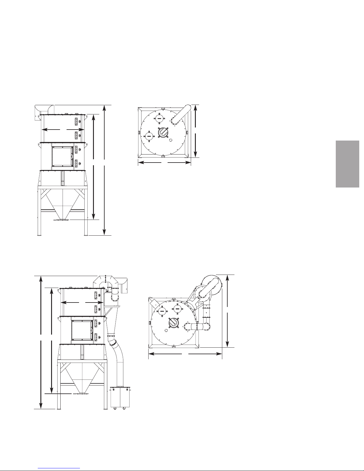
MODELS 18087803 18087801
Uninsulated or Insulated Uninsulated Insulated
Dimensions inches {cm}
A - Height 96.5 {245} 96.5 {245}
B - Height to centerline 81.3 {207} 81.3 {207}
C - Clearance below canister 41.0 {104} 41.0 {104}
D - Depth 53.1 {135} 43.9 {112}
E - Width 42.2 {107} 42.2 {107}
Air inlet/outlet 8 12
Weight lb {kg}
Installed 150 {68} 160 {73}
Shipping 180 {82} 190 {86}
SPECIFICATION NOTES:
Specifications can change without
notice. Check with a Conair representative for the most current information.
Specifications: Dust Collectors
Air outlet
Air
inlet
A
B
C
D
E
De s cr ip ti on l 2- 7
2
De s cri p tion
MODELS DC1 DC2
Performance Characteristics
Pump size range Hp {kW} * 3-7.5 {2.2-5.6} 10-25 {7.5-18.7}
Vacuum line size OD in {mm} 1.5-2.5 {38.1-63.5} 2.25-4.0 {57.2-101.6}
Filter area ft2{M2} 42.8 {4.0} 100.3 {9.3}
Maximum collection capacity ft3{liters} 1.1 {31.1} 2.1{59.4}
Recommended dust collection ft3{liters} 0.75 {21.2} 1.0 {28.3}
Dimensions inches {cm}
A - Height 58.0 {147.3} 67.0 {170.1}
B - Width 15.0 {38.1} 19.0 {48.3}
Depth 20.0 {50.8} 19.0 {48.3}
Weight lb {kg}
Installed 110 {50} 150 {68}
Shipping 140 {64} 280 {127}
Voltage total amps
120V/1 phase/60Hz 1.0 1.0
Compressed air requirement
80-120 psi {5.5-8.3 bars}
SPECIFICATION NOTES:
* Model DC1 works with Conair pump models PSS3, PSS6, PD3, PD5, PD7.5.
Model DC2 works with PSS11, PD10, PD15, PD25.
Specifications can change without notice. Check with a Conair representative for
the most current information.
A
B
in
out
Model DC1 and DC2
TPCS012-0408
Page 24
MODELS PD3 PD5 PD7.5 PD10 PD15 PD25
Motor Type* TEFC TEFC TEFC TEFC TEFC TEFC
Performance
Horsepower 357.5 10 15 25
Standard CFM at Material
Pickup Point @ 10" Hg 52.6 76.6 121.2 154.5 201.1 346.2
Average Sound Level (dbA)
@ 8", 10" and 12" Hg 86 86.3 86 85.8 88.8 93
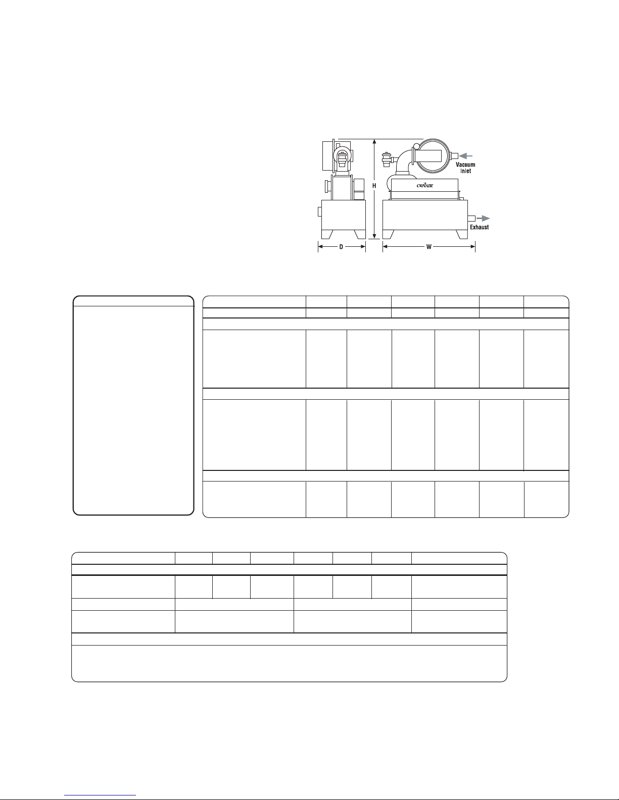
Dimensions in. {mm}
Standard Inlet Size (OD) 1.5 {38} 1.75 {44} 2.25 {57} 2.5 {64} 3.0 {76} 4.0 {102}
Exhaust Line Size (OD) 2.5 {64} 2.5 {64} 2.5 {64} 4.0 {102} 4.0 {102} 4.0 {102}
Height (H) 37 {940} 37 {940} 41 {1041} 51 {1295} 51 {1295} 52 {1321}
Width (W) 35 {889} 35 {889} 35 {889} 39.5 {1003} 39.5 {1003} 39.5 {1003}
Depth (D) 27 {686} 27 {686} 27 {686} 33 {838} 33 {838} 34 {864}
Installed Weight / lb {kg} 325 {147} 325 {147} 370 {168} 625 {283} 640 {290} 960 {435}
Voltage Total Amps
240 7.6 12 18.8 28 39 59
480 3.8 6 9.4 14 19.5 29.5
575 2.9 4.8 7.5 10.7 16 27
* Energy-saving, high efficiency motors
are also available.
Specifications: Positive Di splacement
(PD) Pumps
MODELS PD3 PD5 PD7.5 PD10 PD15 PD25 SUPER (ANY MODEL)
Performance
Average Sound Level (dbA)
@ 8", 10" and 12" Hg
61.9 69.8 76.2 79.3 86.0 90.0 Under 60 dbA
Enclosure Construction Painted Steel Natural Aluminum Painted Steel
Allowance Space for
Service Access / in
48 (Opposite Vacuum Inlet) 36 (Opposite Vacuum Inlet) 36 (Front, Next to Filter)
Dimensions in. {mm}
Height (H) 49 {1245} 64 {1626} 96 {2438}
Width (W) 54 {1372} 55 {1397} 70 {1778}
Depth (D) 32 {813} 36 {914} 50 {1270}
SPECIFICATIONS FOR PUMPS WITH SOUND ENCLOSURES
Specifications not listed below are the same as those listed above. All Sound Enclosures include a cooling fan 115 VAC @ 2 amps.
SPECIFICATION NOTES:
Specifications can change with-
out notice. Check with a Conair
representative for the most current information.
2- 8 l Des cr i pt io n
TPCS026-0408
Page 25
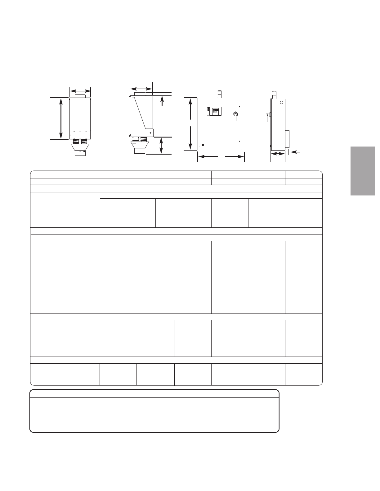
Specifications: CH Series Insulated
Hoppers
Without Integrated Cyclone (Fig. 1)
A
B
C
D
E
With Integrated Cyclone (Fig. 2)
A
BA
D
E
De s cr ip ti on l 2- 9
2
De s cri p tion
TPDS006-0408 REV
Page 26
Specifications: CH Series Insulated
Hoppers
MODEL CH54-70 CH54-85 CH54-99 CH54-114 CH54-129 CH64-158 CH64-187 CH64-215 CH64-248
FIGURE NUMBER Fig. 1 Fig. 1 Fig. 1 Fig. 1 Fig. 1 Fig. 1 Fig. 1 Fig. 1 Fig. 1
Performance characteristics
Capacity ft3{liter} 70 {1982} 85 {2407} 99 {2804} 114 {3228} 129 {3653} 158 {4475} 187 {5296} 215 {6089} 248 {7023}
Capacity @ 35 lb/ft
3
2450 2975 3465 3990 4515 5530 6545 7525 8680
Dimensions inches {cm}
A - Inside diameter 54 {137} 54 {137} 54 {137} 54 {137} 54 {137} 64 {163} 64 {162} 64 {162} 64 {163}
B - Hopper height 101.3 {257}120.1 {305} 132.1 {336} 138.1 {351} 150.1{381} 144.6
{367}
158.6 {403} 174.6 {443} 192.6 {489}
C - Overall height 136.8 {347}154.8 {393} 166.8 {424} 170.8 {434} 182.8 {464} 177.9 {452} 189.9 {482} 207.9 {528} 225.9 {574}
D - Width 69.4 {176} 69.4 {176} 69.4 {176} 69.4 {176} 69.4 {176} 76.0 {193} 76.0 {193} 76.0 {193} 76.0 {193}
E - Depth 69.4 {176} 69.4 {176} 69.4 {176} 69.4 {176} 69.4 {176} 76.0 {193} 76.0 {193} 76.0 {193} 76.0 {193}
Air inlet (OD) 8 {20.3} 8 {20.3}
Air outlet (OD) 8 {20.3} 8 {20.3}
Material discharge (ID) 6 {15.2} 6 {15.2}
Weights lb {kg}
Installed weight (hopper only) 1100 {499}1250 {567} 1450 {658} 1550 {703} 1650 {748} 1850 {839} 2050 {930} 2150 {975} 2250 {1021}
Mounting interfaces
Hopper loader (Top) IT07 IT07 IT07 IT07 IT07 IT07 IT07 IT07 IT07
Material discharge (Bottom) IB03 IB09 IB09 IB09 IB09 IB09 IB09 IB09 IB09
MODEL CH74-245 CH74-366 CH74-487 CH100-450 CH100-675 CH100-900
FIGURE NUMBER Fig. 1 Fig. 1 Fig. 1 Fig. 1 Fig. 1 Fig. 1
Performance characteristics
Capacity ft3{liter} 245 {6938} 366 {10365} 487 {13792} 450 {12743} 675 {19114} 900 {25485}
Capacity @ 35 lb/ft
3
8575 12810 17045 15750 23625 31500
Dimensions inches {cm}
A - Inside diameter 74 {188} 74 {188} 74 {188} 100 {254} 100 {254} 100 {254}
B - Hopper height 170.2 {432} 218.2 {554} 266.2 {676} 199 {505} 249 {632} 297 {754}
C - Overall height 193.7 {492} 241.7 {614} 289.7 {736} 219 {556} 269 {683} 317 {805}
D - Width 90.5 {229.9} 90.5 {229.9} 90.5 {229.9} 120.0 {305} 120.0 {305} 120.0 {305}
E - Depth 90.5 {229.9} 90.5 {229.9} 90.5 {229.9} 120.0 {305} 120.0 {305} 120.0 {305}
Air inlet (OD) 12 {30.5} 12 {30.5}
Air outlet (OD) 12 {30.5} 12 {30.5}
Material discharge (ID) 8 {20.3} 11.875 {30.2}
Approximate weight lb {kg}
Installed weight (hopper only) 3230 {1465} 3830 {1737} 5030 {2282} 9750 {4423} 10800 {4899} 11850 {5375}
Mounting interfaces
Hopper loader (Top) IT07 IT07 IT07 IT07 IT07 IT07
Material discharge (Bottom) IB09 IB09 IB09 IB09 IB09 IB09
Without Integrated Cyclone
Without Integrated Cyclone
SPECIFICATION NOTES:
Specifications can change without
notice. Check with a Conair representative for the most current
information.
IT07
4 equally spaced
mounting clips on a
16.375 in. {416 mm}
diameter bolt circle
IB09
16 bolt holes, 7/16 in.
{11 mm}, on a 16.25 in.
{413 mm} square plate
Top for hopper loaders
Bottom at discharge
2- 1 0 l D es cr ip t io n
TPDS006-0408 REV
Page 27
With Integrated Cyclone
With Integrated Cyclone
Specifications: CH Series Insulated
Hoppers
SPECIFICATION NOTES:
Specifications can change without notice. Check with a Conair
representative for the most
current information.
IT07
4 equally spaced
mounting clips on a
16.375 in. {416 mm}
diameter bolt circle
IB09
16 bolt holes, 7/16 in.
{11 mm}, on a 16.25 in.
{413 mm} square plate
Top for hopper loaders
Bottom at discharge
MODEL CH54-70 CH54-85 CH54-99 CH54-114 CH54-129 CH64-158 CH64-187 CH64-215 CH64-248
FIGURE NUMBER Fig. 2 Fig. 2 Fig. 2 Fig. 2 Fig. 2 Fig. 2 Fig. 2 Fig. 2 Fig. 2
Performance characteristics
C
apacity ft3{liter} 70 {1982} 85 {2407} 99 {2804} 114 {3228} 129 {3653} 158 {4475} 187 {5296} 215 {6089} 248 {7023}
Capacity @ 35 lb/ft
3
2450 2975 3465 3990 4515 5530 6545 7525 8680
D
imensions inches {cm}
A - Inside diameter 54 {137} 54 {137} 54 {137} 54 {137} 54 {137} 64 {163} 64 {162} 64 {162} 64 {163}
B
- Hopper height 101.3 {257}120.1 {305} 132.1 {336} 138.1 {351} 150.1{381} 144.6
{367}
158.6 {403} 174.6 {443} 192.6 {489}
C
- Overall height 140.6 {357}157.6 {400} 169.6 {431} 175.6 {446} 187.6 {477} 182.4 {463} 194.4 {494} 212.4 {539} 230.4 {585}
D - Width 96.4 {245} 96.4 {245} 96.4 {245} 96.4 {245} 96.4 {245} 101.8 {259} 101.8 {259} 101.8 {259} 101.8 {259}
E - Depth 96.4 {245} 96.4 {245} 96.4 {245} 96.4 {245} 96.4 {245} 101.8 {259} 101.8 {259} 101.8 {259} 101.8 {259}
Air inlet (OD) 8 {20.3} 8 {20.3}
Air outlet (OD) 8 {20.3} 8 {20.3}
Material discharge (ID) 6 {15.2} 6 {15.2}
Approximate weight lb {kg}
Installed weight
(hopper and cyclone) 1650 {748}1800 {816} 2000 {907} 2100 {953} 2200 {998} 2400 {1089} 2600 {1179} 2700 {1225} 2800 {1270}
Mounting interfaces
Hopper loader (Top) IT07 IT07 IT07 IT07 IT07 IT07 IT07 IT07 IT07
Material discharge (Bottom) IB03 IB09 IB09 IB09 IB09 IB09 IB09 IB09 IB09
MODEL CH74-245 CH74-366 CH74-487
FIGURE NUMBER Fig. 2 Fig. 2 Fig. 2
Performance characteristics
Capacity ft3{liter} 245 {6938} 366 {10365} 487 {13792}
Capacity @ 35 lb/ft
3
8575 12810 17045
Dimensions inches {cm}
A - Inside diameter 74 {188} 74 {188} 74 {188}
B - Hopper height 170.2 {432} 218.2 {554} 266.2 {676}
C - Overall height 263.5 {669} 311.5 {791} 479.5 {1218}
D - Width 118.6 {301} 118.6 {301} 118.6 {301}
E - Depth 118.6 {301} 118.6 {301} 118.6 {301}
Air inlet (OD) 12 {30.5}
Air outlet (OD) 12 {30.5}
Material discharge (ID) 8 {20.3}
Approximate weight lb {kg}
Installed weight (hopper and cyclone) 3780 {1715} 4380 {1987} 5580 {2531}
Mounting interfaces
Hopper loader (Top) IT07 IT07 IT07
Material discharge (Bottom) IB09 IB09 IB09
De s cr ip ti on l 2- 11
2
De s cri p tion
TPDS006-0408 REV
Page 28
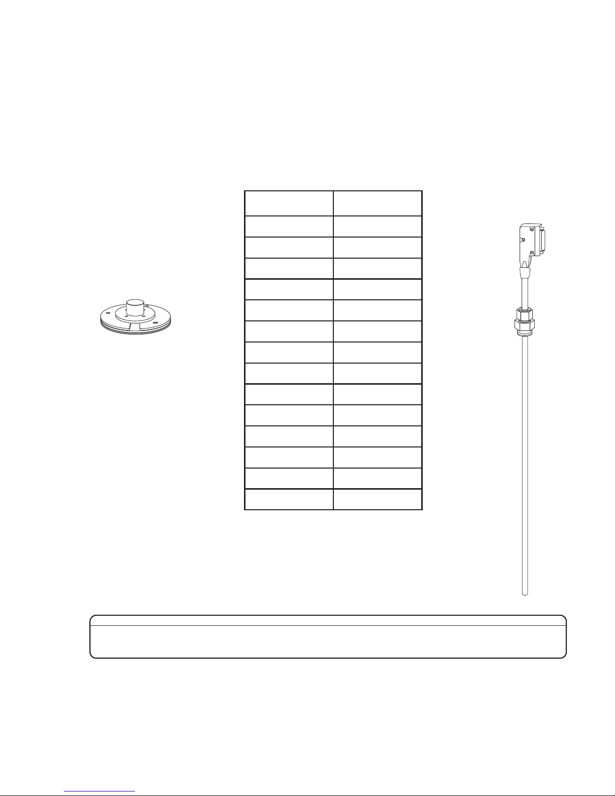
Angled Probe
Allows the DM-II to be used on
hoppers that have insufficient
clearance for correctly mounting
the probe around loading devices.
Probe Mounting
Adapter Kit
(Includes half coupling,
two mounting plates,
screws and gasket)
NOTE: The mounting adapter
kit will only be included if the
DM-II was ordered as a retrofit kit. Otherwise, the adapter
plate will already be in place
on the hopper.
The DM-II package includes:
●
Drying monitoring probe
●
Connecting cable
●
Pre-wired dryer panel
●
Light tower
Specifications: Dr ying Monitor, DM-II
Model
✐
SPECIFICATION NOTES:
Specifications can change without notice. Check with a Conair representative for the most current information.
Drying Hopper # Conair Part #
CH 54-70 1819080140
CH 54-85 1819080141
CH 54-99 1819080142
CH 54-114 1819080123
CH 54-129 1819080143
CH 64-158 1819080125
CH 64-187 1819080126
CH 64-215 1819080127
CH 64-248 1819080144
CH 74-245 1819080126
CH 74-366 1819080145
CH 100-450 1819080132
CH 100-675 1819080133
CH 100-900 1819080134
2- 1 2 l D es cr ip t io n
Page 29

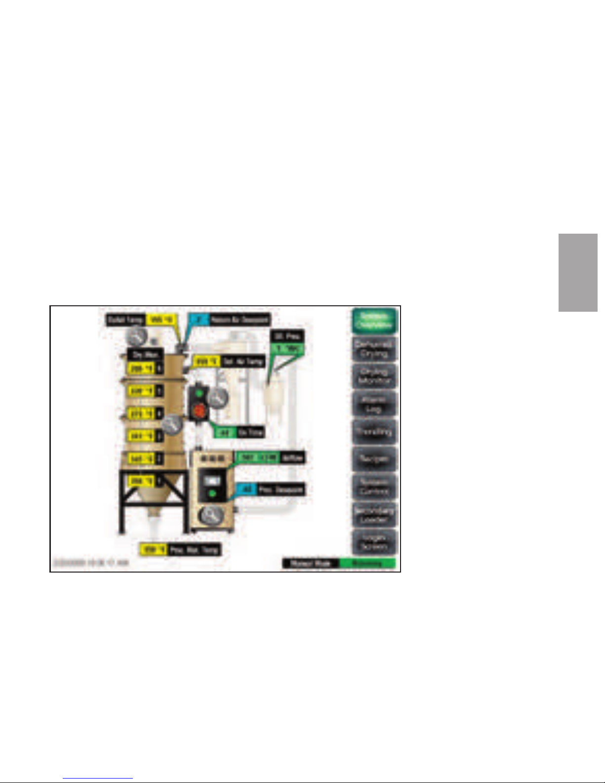
Energ ySmart Dryer Control Options
• Visual alarms - The visual alarm is a blinking red alarm light that alerts the user to
any shut down alarm.
• Trending screens - The trending screens display temperature, air flow, dew point and
differential pressure of the EnergySmart Dryer System. Each can be used to graph
real-time data of a running dryer system.
• Recipe storage screen - The recipe storage screen is used to store and instantly recall
specific dryer parameters that are used with different types of material. Up to 99 dryer
recipes can be saved within the control.
• Loading control screens - Dedicated screens control the function and activation of up
to two (2) optional receivers. Loading, dump and purge times can be individually
altered for each receiver.
• Communications - Allows the dryer to be networked to industrial control systems.
De s cr ip ti on l 2- 13
2
De s cri p tion
Page 30

2- 1 4 l D es cr ip t io n
Page 31

In s ta ll at io n l 3 -1
Installation
Ins t a l l a tion - G e n e r a l . . . . . . . . . . . . . . . . . . . . . 3-5
Unpacking the EnergySmart™ Dryer System
components . . . . . . . . . . . . . . . . . . . . . . . . . . . . . 3-6
Preparing for installation . . . . . . . . . . . . . . . . . . . . . . . 3-7
Positioning the CH hopper floor stand . . . . . . . . . . . . . . 3-8
Installation of the HTC control
(Models HTC 30, 60 and 90) . . . . . . . . . . . . . . . . . 3-9
(Models HTC 120) . . . . . . . . . . . . . . . . . . . . . . . . 3-10
(Models HTC 180 and 270) . . . . . . . . . . . . . . . . . 3-10
Location and mounting of the HTC heater assembly
(Models HTC 30, 60 and 90) . . . . . . . . . . . . . . . . 3-11
(Models HTC 120) . . . . . . . . . . . . . . . . . . . . . . . . 3-11
(Models HTC 180 and 270) . . . . . . . . . . . . . . . . . 3-11
Installing the CH hopper cone section . . . . . . . . . . . . . 3-12
Installing the CH hopper door, upper and lid sections . . 3-13
Installing the cyclone (optional) . . . . . . . . . . . . . . . . . . 3-17
Installing the drying monitor probe . . . . . . . . . . . . . . . 3-22
Installing the receiver(s) (optional). . . . . . . . . . . . . . . . 3-25
Installing the purge valve(s) (optional) . . . . . . . . . . . . . 3-25
Installing the modular distribution box(s) (optional) . . . . 3-25
Securing the CH hopper to the floor . . . . . . . . . . . . . . . 3-26
Location and mounting of the GasTrac heater . . . . . . . . 3-27
Location and mounting of the dust collector (optional). . 3-28
Location and mounting of the vacuum pump(s)
and dust collector(s) (optional) . . . . . . . . . . . . . . . 3-30
Po s i t ioning the d r y e r o n the floor . . . . . . . . . . . 3 - 3 1
Rem o v i n g t h e cab l e tie from the d esiccant
whe e l (W60 0 - 1 0 0 0 m o d e l s ) . . . . . . . . . . . . 3-3 1
S E C T I O N
3
3
In s tal l a tio n
Page 32

Installation ( con t inu e d)
Ins t a l l i n g t h e r e g e n e r a t i on e x h aust c over . . . . . 3 -31
Ins t a l l i n g t h e r e t u r n a i r ada pte r . . . . . . . . . . . . 3- 3 2
Ins t a l l i n g t h e r e t u r n a i r inl e t and air outlet
ada pte r s (W16 0 0 - 5 0 0 0 m o d e l s) . . . . . . . . . 3-33
Ins t a l l i n g t h e o v e r h e a d p r o c ess a i r
duc t (W320 0 - 5 0 0 0 m o d e l s ) . . . . . . . . . . . . 3 - 3 4
Ins t a l l a tion - P i p i n g /Hoses . . . . . . . . . . . . . . . . . 3-35
Opt i o n a l h a r d pip i n g kit s . . . . . . . . . . . . . . . . . 3-36
Con n e c t i n g t h e h e a t sourc e s . . . . . . . . . . . . . . 3-37
Hop p e r tem p e r a t u r e c o n t r o ller ( H TC) a s
hea t source . . . . . . . . . . . . . . . . . . . 3-37
Gas Tr a c a s he a t source . . . . . . . . . . . . . . 3 - 3 8
Con n e c t i n g t h e d r yer to the h e a t s o u r c e . . . . . . 3 - 3 9
Con n e c t i n g t h e d u s t col l e c t o r ( o p t i onal) . . . . . . 3-40
Con n e c t i n g t h e c y clone separ a tor (opti o n a l ) . . . . 3 - 4 1
Ins t a l l i n g t h e D w y e r 6 4 1 air velocit y
tra n s m i t t er . . . . . . . . . . . . . . . . . . . . . . . 3 - 4 2
Ins t a l l i n g t h e l e v e l s wit c h (opt i o n a l ) . . . . . . . . . 3- 4 4
Adj u s t i n g t h e lev e l sens o r (opt i o n a l ) . . . . . . . . . 3-45
Ins t a l l i n g t h e p r o c e s s p r o t e ction RTD sensor . . . 3 - 4 6
Loc a ti o n of the process material temperature
pro b e (RT D ) . . . . . . . . . . . . . . . . . . . . . . 3 - 4 7
Ins t a l l i n g t h e G a s Trac RTD sensor . . . . . . . . . . 3 - 4 8
Ins t a l l i n g t h e r e t u r n a i r dew point line . . . . . . . 3 - 4 9
Ins t a l l a tion - M a i n Po wer C o nnections . . . . . . 3-51
Connecting main power to the dryer . . . . . . . . . . . . . . 3-52
Connecting main power to the HTC
(Models HTC 30, 60, 90 and 120) . . . . . . . . . . . . . 3-53
3- 2 l Ins ta l la ti on
Page 33

Installation ( con t inu e d)
(Models HTC 180 and 270) . . . . . . . . . . . . . . . . . 3-54
Connecting main power to the GasTrac . . . . . . . . . . . . 3-56
Connecting main power to the vacuum pump(s)
(optional) . . . . . . . . . . . . . . . . . . . . . . . . . . . . . . 3-57
Connecting main power to the dust collector(s)
(optional) . . . . . . . . . . . . . . . . . . . . . . . . . . . . . . 3-57
Ins t a l l a tion - C o n v e y ing L i n es . . . . . . . . . . . . . . 3-59
Con n e c t i n g t h e c o n v e y i ng l i n es t o t h e
rec e i v e r ( s) ( o p t ional) . . . . . . . . . . . . . . . . 3-60
Con n e c t i n g t h e c o n v e y i ng l i n es t o t h e purg e
val v e s (op t i o n a l ) . . . . . . . . . . . . . . . . . . . 3 - 60
Con n e c t i n g t h e c o n v e y i ng l i n es t o t h e vacu u m
pum p ( s ) an d dust collect o r ( s ) ( o p t i o n al) . . . 3 - 61
Ins t a l l a tion - W ater L i nes . . . . . . . . . . . . . . . . . 3- 6 3
Typic a l water lines installa tio n drawing . . . . . . . 3-64
Con n e c t i n g t h e a f t e r c o oler/inter c o o l e r
and option a l prec o o l e r ( W 6 0 0 - 1 000) . . . . . . 3 - 6 5
Con n e c t i n g t h e a f t e r c o oler/inter c o o l e r
and option a l prec o o l e r ( W 1 6 0 0 - 5000) . . . . . 3-66
Ins t a l l a tion - C o n t r o l a n d Com m u n i c ations
Wir i n g . . . . . . . . . . . . . . . . . . . . . . . . . . . . . 3-67
Con n e c t i n g t h e H T C to the HTC c o ntroller . . . . . 3-68
Con n e c t i n g t h e R T D s e n s o rs ( H T C o n l y ) . . . . . . . 3 -70
Con n e c t i n g t h e G a s Trac RTD sensors . . . . . . . . . 3 - 7 2
Con n e c t i n g t h e d r ying monito r probe to
the dryer . . . . . . . . . . . . . . . . . . . . . . . . 3-73
Con n e c t i n g t h e r e c e i v e r t o t h e leve l
switch (optio n a l ) . . . . . . . . . . . . . . . . . . . 3 -74
In s ta ll at io n l 3 -3
3
In s tal l a tio n
Page 34

3- 4 l Ins ta l la ti on
Installation ( con t inu e d)
Con n e c t i n g t h e E n e r g y S m a r t D r y e r con t r o l
to system compone n t s . . . . . . . . . . . . . . . 3 - 7 5
Ins t a l l a tion - C o m p r e ssed A ir L i n e s . . . . . . . . . . . 3-85
Con n e c t i n g t h e c o m p r e s sed a i r l i n e s
(op t i o n a l ) . . . . . . . . . . . . . . . . . . . . . . . . 3-86
Ins t a l l a tion - G a s Pipi n g and Exhaust Flue . . . . . . 3-87
Typic a l gas line installa tio n drawing . . . . . . . . . 3-88
Ins t a l l i n g t h e C o n a i r G a s Trac . . . . . . . . . . . . . . 3-89
Con n e c t i n g t h e g a s and the exhaust flue to
the GasTr a c . . . . . . . . . . . . . . . . . . . . . . 3 - 9 2
Ins t a l l a tion - Te s ting . . . . . . . . . . . . . . . . . . . . . 3 - 95
Che c k i n g f o r prop e r air flow . . . . . . . . . . . . . . 3-96
Te s t i ng t h e v a r i a b le f r e quency drive (VFD) . . . . . 3 - 9 9
Te s t i ng t h e i n s t a l la tion o f t h e H T C . . . . . . . . . 3- 1 00
Che c k i n g t h e gas and electrica l syste m s
of the GasTr a c . . . . . . . . . . . . . . . . . . . . 3 - 1 02
Te s t i ng t h e i n s t a l la tion o f t h e G a s Trac . . . . . . . 3-103
Te s t i ng t h e p r i m a r y rec e i v e r ( o p t i o n al) . . . . . . 3-1 0 5
Te s t i ng t h e s e c o n d ar y r e c e i v e r ( o p t ional) . . . . . 3 - 107
Con f i g u r i ng t h e D w y e r 6 4 1 air veloci t y
tra n s m i t t er . . . . . . . . . . . . . . . . . . . . . . 3-109
Con f i g u r i ng t h e D M - I I d r ying
mon i t o r . . . . . . . . . . . . . . . . . . . . . . . . 3 - 1 10
Con f i g u r i ng t h e l e v e l s wi t c h (op t i o n a l ) . . . . . . . 3-110
Usi n g comm u n i c a t i o n s ( o p t ional) . . . . . . . . . . 3 - 1 1 3
Page 35

Installation - General
In s ta ll at io n - Ge ne ra l l 3 -5
3
In s tal l a tio n
Page 36

Unpacking the EnergySmart™
Dryer System Components
Because of their size and shape and the multiple sizes in which the hopper is
available, the components of the EnergySmart Dryer System come packaged for
shipping in the best available manner. The EnergySmart System components
include, depending on the model and options ordered:
! EnergySmart Dryer with TouchView Technology - Allen-Bradley control
! CH Hopper - with or without integrated cyclone - optional
! Heater (HTC or GasTrac)
! Dust Collector(s) - optional
! DM-II Drying Monitor
! Receiver(s) - up to two (2) - optional
! Vacuum pump - up to two (2) - optional
! Hard piping kit - optional
1 For the EnergySmart Dryer System components that are mounted to
pallets, remove the hardware securing each component to its pallet, then
remove the component from the pallet. With a forklift, hoist or crane carefully
move the components to their approximate installation locations.
2 Remove all packing material, protective paper, tape and plastic, including any
inserted inside the components.
3 Carefully inspect all components to ensure no damage occurred during ship-
ping, and that you have all the necessary hardware. If any damage is found,
notify the shipping agent immediately.
4 Take a moment to record serial numbers and electrical power specifications
in the blanks provided on the back of the User Guide's title page. This information will be helpful if you ever need service or parts.
5 You are now ready to begin installation. Follow the preparation steps in the
next section.
6 Determine if your application is electric or gas. Disregard installation
steps for options not used.
3- 6 l Ins ta l la ti on - G en er al
NOTE: Some components may
be strapped to their shipping
pallet, remove as necessary.
✐
Page 37

3
In s tal l a tio n
In s ta ll at io n - Ge ne ra l l 3 -7
Preparing for Installation
The EnergySmart Dryer System is easy to install if you plan the location and
prepare the installation area properly.
1 Make sure the installation area provides:
❒
Grounded power sources supplying the correct voltages and currents for your system components. Check each component's serial
tag for the correct amps, voltage, phase and cycles. Field wiring to
each component should be completed by qualified electrical personnel.
All electrical wiring should comply with your region's electrical codes.
❒
Minimum clearance above and around each component for safe
operation and maintenance. Refer to the component manuals sup-
plied with your EnergySmart Dryer System to determine minimum
clearances needed for each component.
❒
A mounting area that will support the weight of the fully loaded CH
Hopper, floor stand and the other system components. Refer to the
specifications supplied with your EnergySmart Dryer System for the
weights of each component.
❒
A source of water for the aftercooler/intercooler or optional precooler of the dryer. The water source must be tower, city or chiller
water at temperatures of 45° to 85°F {7° to 29°C}. Refer to the specifications supplied with your system for the flow rate. Piping should be
installed to the dryer location. Flexible hose can be used to connect
the water pipes to the aftercooler/intercooler or optional precooler.
❒
If the heat source supplied with your EnergySmart Dryer System is
a GasTrac (CGT), the installation location must provide for an
exhaust flue and gas lines that meet all applicable local, regional
and national codes. Conair recommends that the GasTrac should have
a dedicated vertical stack that exits the building through a rain-protected
roof penetration. See Installation section entitled, Connecting the Gas
and the Exhaust Flue to the GasTrac.
❒
Material and conveying lines installed. If you plan to use optional
vacuum receivers to fill the CH Hopper, install conveying lines to the
hopper location as well as to the optional vacuum pump(s) and its associated dust collector(s) used within your EnergySmart Dryer System.
Page 38

3- 8 l Ins ta l la ti on - G en er al
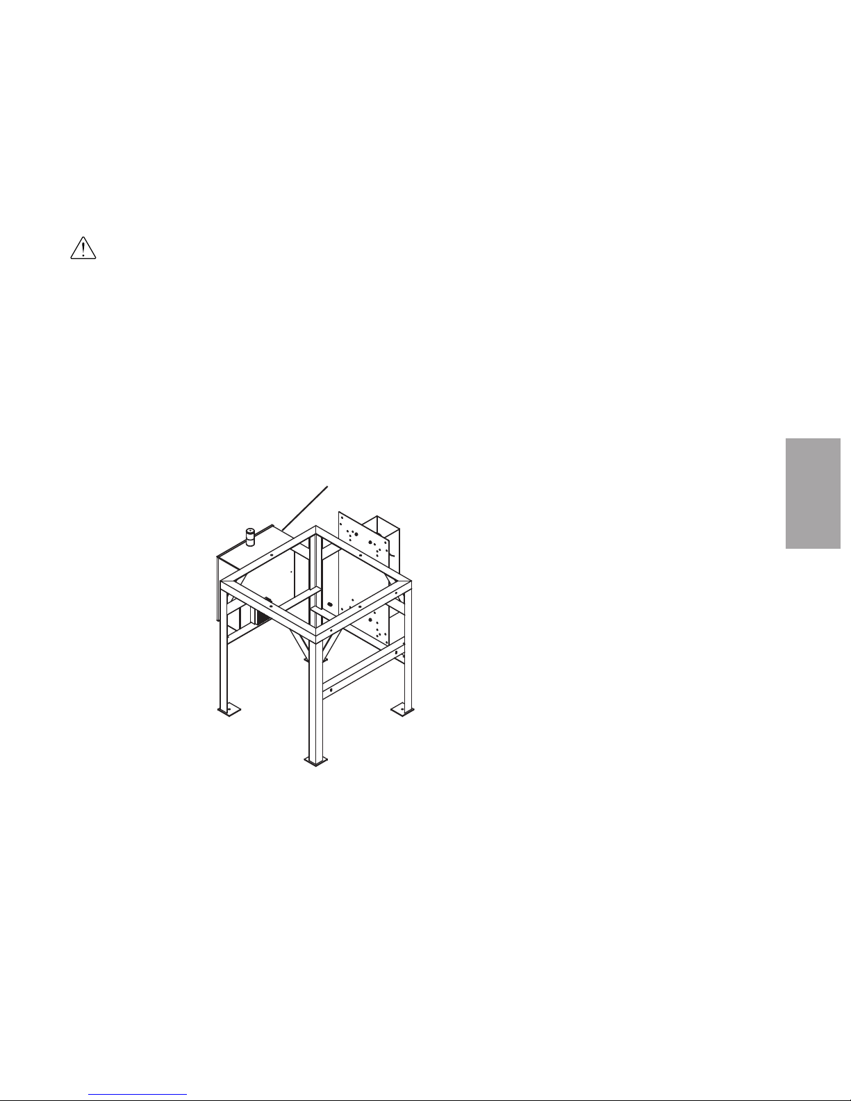
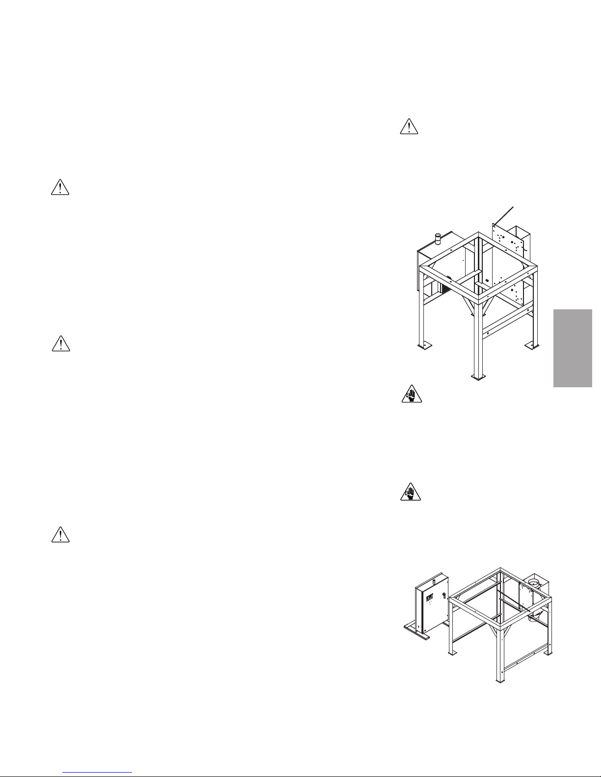
Positioning the CH Hopper Floor
Stand
WARNING: You are responsible for the structural integrity of this installation.
CAUTION: Care should be taken while moving the main CH Hopper floor stand and
sections to ensure that no damage occurs during assembly.
IMPORTANT: You will need to consider the installation of your entire dryer system
before permanently placing any system component, see Installation - Piping and
Hoses for reference.
Due to the varying size of Conair CH Hoppers, Conair recommends:
• Following all applicable local building and safety codes
1 Make sure the installation location for the CH Hopper meets all provisions for
clearances, will support the weight of the fully loaded hopper and provides
space for the installation of the other system components, such as optional
receivers. See the specifications and drawings supplied with your system for
details.
2 Using a forklift, hoist or crane, move the floor stand to its installation location.
NOTE: For EnergySmart Dryer
Systems supplied with "small"
hoppers, the floor stand and cone
section may be pre-assembled
from Conair.
✐
Page 39
3
In s tal l a tio n
In s ta ll at io n - Ge ne ra l l 3 -9
Installation of the HTC Control
(Mode ls HT C 30, 60 , a nd 90 )
CAUTION: You are responsible for the structural integrity of this installation.
NOTE: The HTC control is shipped mounted on the left side of the CH Hopper floor stand
on models 30, 60 and 90.
NOTE: If, by using your own provisions, you change the mounting arrangement of the
control center to a wall mount unit, it must be mounted 6 inches {152.4 mm} off of the
wall to provide clearance for the heat sink.
✐
✐
HTC Control
Center
(continued)
NOTE: If using a GasTrac for the
drying system heat source, see
Installation section entitled,
Installing the CH Hopper Cone
Section.
✐
Page 40

Installation of the HTC Control
(c on ti nu ed ) (Mod el HT C 120)
CAUTION: You are responsible for the structural integrity of this
installation.
1 Securely bolt the HTC control to the left side of the floor stand. Use the
supplied locking fasteners to securely mount the HTC control center to the floor
stand to prevent vibration-induced loosening.
NOTE: If, by using your own provisions, you change the mounting arrangement of the control center to a wall mount unit, it must be mounted 6 inches {152.4 mm} off of the wall to
provide clearance for the heat sink.
Installation of the HTC Control
(c on ti nu ed ) ( Mo de ls HTC 180 and 27 0)
CAUTION: You are responsible for the structural integrity of this installation.
1 Move the control center into
its final location for operation
(see figure to the right). The
control center must be positioned close enough to the
hopper to allow connection of
the RTD temperature probe.
The control center can be
mounted to a wall, the hopper
frame or a floor stand with
customer supplied provisions.
NOTE: If, by using your own provisions, you change the mounting arrangement of the control center to a wall mount unit, it must be mounted 6 inches {152.4 mm} off of the wall to
provide clearance for the heat sink.
✐
HTC Control Center
(Free-Standing)
✐
HTC Control
Center
✐
NOTE: If the lengths of the process
and process protection RTD wiring
are too short for your installation,
contact Conair Parts Department
(800.458.1960) to purchase
extension cables. From outside the
United States, call 814.437.6861.
(continued)
3- 1 0 l I ns ta ll a ti on - Ge ne r al
NOTE: If using a GasTrac for the
drying system heat source,
see
Installation section entitled,
Installing the CH Hopper Cone
Section.
✐
Page 41
CAUTION: Always disconnect
and lock out the main power
sources before making electrical connections. Electrical
connections should be made
only by qualified personnel.
CAUTION: Check the disconnect with a volt meter to
ensure that the power is off.
Location and Mounting of the HTC
Heater Assembly
(Mode ls HT C 30, 60 and 90)
CAUTION: You are responsible for the structural integrity of this installation.
NOTE: The HTC heater assembly is shipped mounted to the back of the floor stand on
Models 30, 60 and 90 (see figure to the right).
NOTE: The heater is prewired to the control box on HTC Model 30, 60 and 90.
Location and Mounting of the HTC
Heater Assembly (M od el HTC 120)
CAUTION: You are responsible for the structural integrity of this installation.
1 Securely bolt the HTC heater assembly to the back of the floor stand (see
figure to the right). Use the locking fasteners provided to securely mount the
heater assembly to the floor stand to prevent vibration-induced loosening.
NOTE: The heater is prewired to the control box on HTC Model 120.
Location and Mounting of the HTC
Heater Assembly
(Mode ls HT C 180 and 270)
CAUTION: You are responsible for the structural integrity of this installation.
1 Securely bolt the HTC heater assembly to the back of the floor stand (see
figure to the right). Use the locking fasteners provided to securely mount the
heater assembly to the floor stand to prevent vibration-induced loosening.
2 Refer to the wiring diagram to make the wiring connections for the heater
and control box. Only a qualified electrician should make the wiring connections between the control and the heater. The customer must supply the appropriately-sized wire and conduit to make connections.
✐
HTC Heater
HTC Heater
IMPORTANT: Always refer
to the wiring diagrams that
came with your HTC before
making electrical connections.
✐
In s ta ll at io n - Ge ne ra l l 3 -1 1
3
In s tal l a tio n
✐
Page 42

Installing the CH Hopper Cone
Section
Install the hopper cone section on the floor stand using the following steps.
IMPORTANT: You will need to consider the location of the CH Hopper’s delivery air inlet in relation to the dryer installation location for proper setup.
IMPORTANT: You will need to consider the location of the HTC heater outlet
in relation to the CH Hopper air inlet location for proper setup.
1 If any hoses, wires, etc. were attached to the floor stand and cone
section (for shipping purposes), make sure they are positioned away
from the mating surfaces of the assemblies so they will not be damaged
during this procedure.
2 Using a forklift, hoist or crane, lift the cone section assembly above
the floor stand.
CAUTION: To prevent accident and injury, lift the cone and hopper sections
onto the floor stand assembly using a forklift, hoist or crane.
3 Set the cone section on the floor stand as shown. Make sure the holes
in the cone section mounting lugs align with the holes in the top of the
floor stand assembly.
4 Secure the cone section to the floor stand assembly using the supplied
hardware.
NOTE: For EnergySmart Dryer
Systems supplied with "small"
hoppers, the floor stand and cone
section may be pre-assembled at
the factory. If your floor stand
and cone section are pre-assembled and you have secured the
floor stand to the floor,
see
Installation section entitled,
Installing the CH Hopper Door,
Upper and Lid Sections.
✐
3- 1 2 l I ns ta ll a ti on - Ge ne r al
NOTE: If using carbon steel hop-
pers, be sure to clean out the
hopper prior to use. Conair
applies a rust inhibitor that must
be removed several hours before
using the hopper.
✐
Page 43

Installing the CH Hopper Door,
Upper and Lid Sections
IMPORTANT: Before installing the hopper door, upper (if applicable), and
lid sections of the CH Hopper, careful consideration should be given to
the following:
• When installing the hopper door section, make sure the hopper door is posi-
tioned to allow easy access into the hopper to aid in installation and to facilitate
hopper cleaning and maintenance in the future.
• When installing the hopper lid section, make sure to identify the location of the
hopper’s return air outlet. The lid section has multiple piping options that can be
connected to an optional cyclone or traditional CH Hopper outlet, then to an
optional dust collector and finally to the dryer’s return air inlet. Consider all piping/hosing possibilities when installing the dryer, heater (gas or electric), optional
dust collector and optional cyclone before making the installation permanent.
Hoppe r D oo r Section
To install the hopper door section of the CH Hopper:
1 Apply sealer around the lip on the top of the cone section.
2 Using a forklift, hoist or crane, lift the hopper door section assembly above
the cone section.
CAUTION: To prevent accident and injury, lift the hopper door section onto the
cone section using a forklift, hoist or crane.
NOTE: When applying the sealer,
do not cover the holes in the cone
section lip. Apply the sealer
around the holes so you will have
a good seal but not interfere with
the mounting hardware that will
be used to secure the hopper
door section to the cone section.
✐
✒
TIP: Conair recommends applying
strip and stick sealer 1/8 inches
{3.2 mm} from the inside to the
edge of the CH Hopper.
NOTE: When installing the hopper
door section, make sure the hopper door is positioned to allow
easy access into the hopper to
aid in the continuing installation
and to facilitate hopper cleaning
and maintenance in the future.
✐
In s ta ll at io n - Ge ne ra l l 3 -1 3
3
In s tal l a tio n
(continued)
Page 44

Installing the CH Hopper Door,
Upper and Lid Sections (c on tin ue d)
Hoppe r D oo r Section ( co nt in ued )
3 Set the hopper door section on the cone section as shown. As the hopper
door section is positioned on the cone section, make sure the holes in the hopper
door section align with the holes in the cone section.
4 Secure the hopper door section to the cone section using the supplied
hardware.
3- 1 4 l I ns ta ll a ti on - Ge ne r al
(continued)
Page 45

Installing the CH Hopper Door,
Upper and Lid Sections (continued)
Hoppe r U pp er Section(s ) ( I f App l ica b le)
To install the hopper upper section(s) of the CH Hopper:
1 Apply sealer around the lip on the top of the hopper door section.
2 Using a forklift, hoist or crane, lift the hopper upper section assembly
above the hopper door section.
CAUTION: To prevent accident and injury, lift the hopper upper section onto the
hopper door section using a forklift, hoist or crane.
IMPORTANT: Line up the sight glasses of the hopper upper section(s) with the sight
glasses of the hopper door section.
3 Set the hopper upper section on the hopper door section. As the hopper
upper section is positioned on the hopper door section, make sure the holes in
the upper section align with the holes in the door section.
4 Secure the hopper upper section to the hopper door section using the
supplied hardware.
NOTE: If more than one (1) hopper upper section is to be installed, repeat the steps
detailed in this section for each hopper upper section.
✐
NOTE: When applying the sealer,
do not cover the holes in the hopper door section lip. Apply the
sealer around the holes so you will
have a good seal but not interfere
with the mounting hardware that
will be used to secure the hopper
upper section to the hopper door
section.
✐
✒
TIP: Conair recommends applying
strip and stick sealer 1/8 inches
{3.2 mm} from the inside to the
edge of the CH Hopper.
In s ta ll at io n - Ge ne ra l l 3 -1 5
3
In s tal l a tio n
(continued)
Page 46

Installing the CH Hopper Door,
Upper and Lid Sections (continued)
Hoppe r L id Section
IMPORTANT: Improper mounting of the hopper lid will cause interference when
installing the DM-II monitor probe and optional integrated cyclone. See the illustration below for recommended hopper lid mounting locations.
To install the hopper lid section of the CH Hopper:
1 Apply sealer around the lip on the top of the hopper door or hopper upper
section, if applicable.
2 Using a forklift, hoist or crane, lift the hopper lid section assembly above
the hopper door or hopper upper section.
3 Set the hopper lid section on the hopper door or hopper upper section as
shown below. As the hopper lid section is positioned on the hopper door or
hopper upper section, make sure the holes in the hopper lid section align with
the holes in the hopper door or hopper upper section.
4 Secure the hopper lid section to the hopper door or hopper upper section
using the supplied hardware.
CAUTION: To prevent accident and injury, lift the hopper lid section onto the hopper
door or hopper upper sections using a forklift, hoist or crane.
NOTE: When applying the sealer,
do not cover the holes in the
upper section lip. Apply the sealer
around the holes so you will have
a good seal but not interfere with
the mounting hardware that will
be used to secure the hopper lid
section to the hopper upper
section.
✐
✒
TIP: Conair recommends applying
strip and stick sealer 1/8 inches
{3.2 mm} from the inside to the
edge of the CH Hopper.
WARNING: To accomplish the
following steps, it may be necessary for personnel to enter the
CH Hopper assembly. If it is
necessary to enter the hopper
assembly, all applicable OSHA
procedures for working within
a confined space MUST BE
followed.
3- 1 6 l I ns ta ll a ti on - Ge ne r al
Page 47

Installing the Cyclone (optional)
The optional cyclone separator is designed to be mounted to the return air outlet of
the CH Hopper.
IMPORTANT: The optional cyclone is designed to be connected to the return air circuit of the CH Hopper, then connected to an optional dust collector or to the dryer’s
air inlet.
To install the cyclone to the CH Hopper:
1 Using a forklift, hoist or crane, raise the cyclone’s mounting bracket to its
installation location on the side of the CH Hopper. Installation location
depends upon your system setup.
2 Remove the five (5) bolts located on the top of the lid of the hopper. The
removal of the five (5) bolts is dependent upon the installation location of the
cyclone.
3 Remove the five (5) bolts located on the hopper upper section or hopper
door section of the hopper. The removal of the five (5) bolts is dependent
upon the installation location of the cyclone.
CAUTION: To prevent accident and injury, move the cyclone separator to its mounting location using a forklift, hoist or crane.
In s ta ll at io n - Ge ne ra l l 3 -1 7
3
In s tal l a tio n
Top Bolt
Pattern
Bottom Bolt
Pattern
(continued)
IMPORTANT: Reference your
system layout drawings for
the correct cyclone bracket
bolt pattern usage before it
is installed.
Page 48
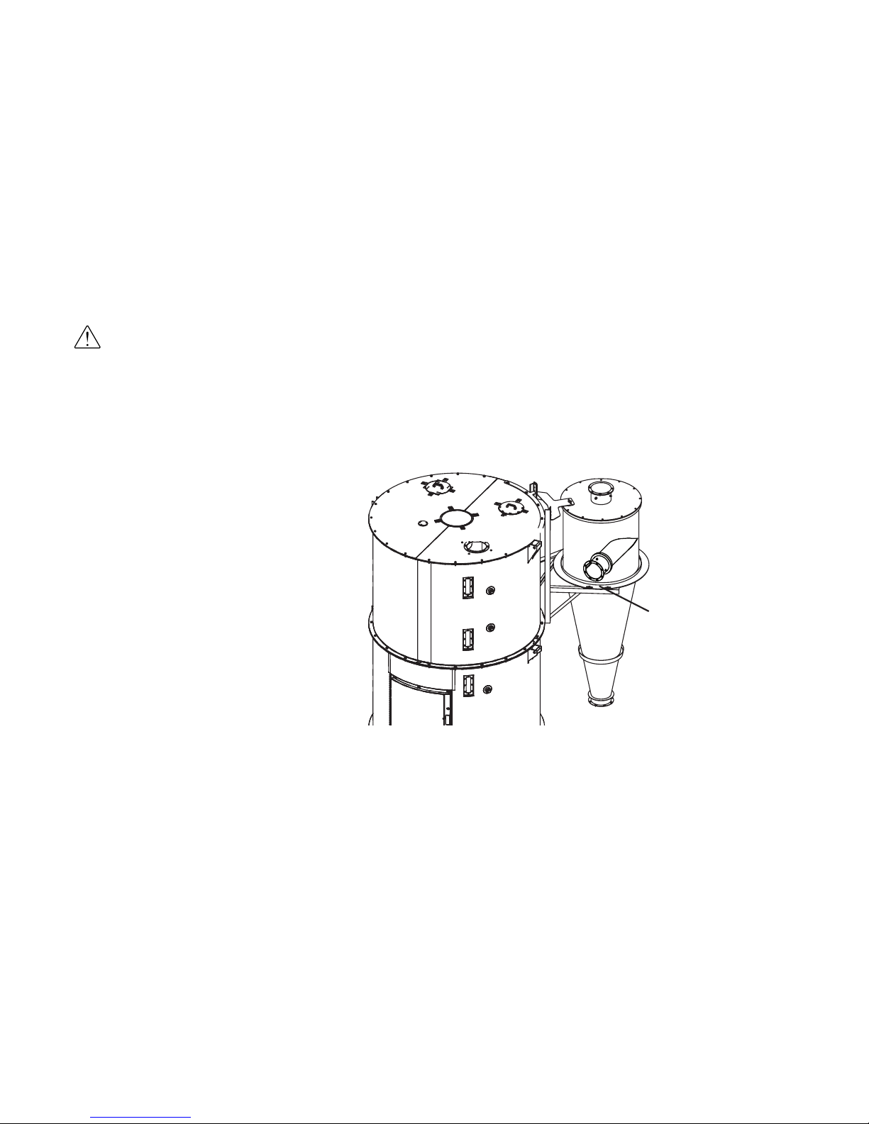
Installing the Cyclone (optional) (continued)
4 Bolt the cyclone bracket to the CH Hopper, using the hardware removed
in Steps 2 and 3. Do not fully tighten the bolts, the cyclone installation may
need to be adjusted for hard piping of the cyclone’s inlet and outlet ports.
5 Using a forklift, hoist or crane, raise the cyclone body to its installation
location on the bracket mounted to the CH Hopper. Installation location
depends upon your system setup.
6 Mount the cyclone body to its installation location on the bracket using the
supplied hardware. Do not tighten the bolts, the cyclone installation may need
to be adjusted for hard piping of the cyclone’s inlet and outlet ports.
7 Locate the three (3) 90 degree pieces of tubing. These pieces will connect
the CH Hopper to the cyclone.
8 Bolt two (2) of the pieces of 90 degree tubing together using the supplied
hardware. Be sure to place the supplied gasket between the two (2) pieces of
tubing before tightening the tube bolts. One of the pieces includes the dew point
return port; the port should be located on the same end as the connection of the
two (2) pieces of 90 degree tubing.
CAUTION: To prevent accident
and injury, move the cyclone
separator to its mounting location using a forklift, hoist or
crane.
3- 1 8 l I ns ta ll a ti on - Ge ne r al
(continued)
Bolts (4)
(Two (2) for each
side)
Page 49
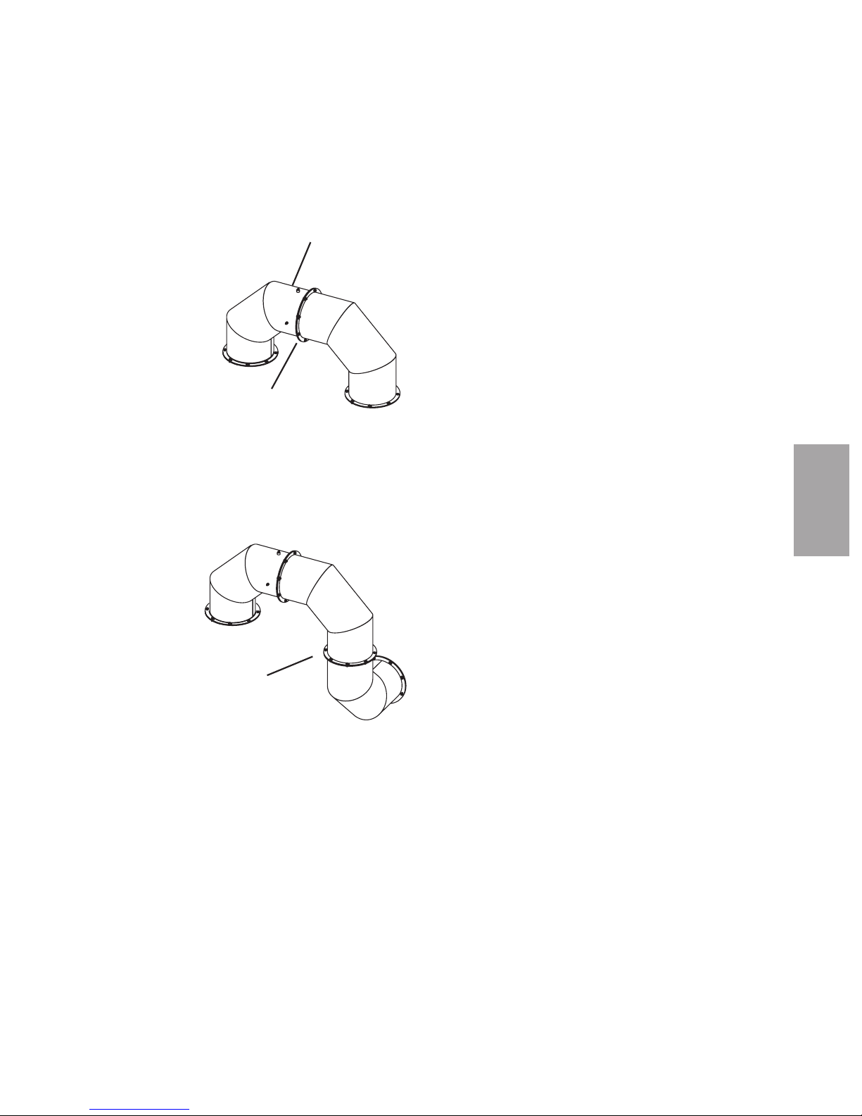
Installing the Cyclone (optional) (continued)
9 Bolt the third piece of 90 degree tubing to the assembly in Step 8 using the
supplied hardware. The third piece of 90 degree tubing should be bolted to
the end of the assembly in Step 8 that DOES NOT have the dew point return
port. Be sure to place the supplied gasket between the two (2) pieces of tubing
before tighten the tube bolts.
10 Loosely bolt the now finished tubing assembly to the CH Hopper’s return
air outlet and to the cyclone’s air inlet, using the supplied hardware. Be
sure to place the supplied gaskets between the tubing assembly and the CH
Hopper outlet and cyclone air inlet before tightening bolts. Mounting location
is dependent upon the installation location of the cyclone.
In s ta ll at io n - Ge ne ra l l 3 -1 9
3
In s tal l a tio n
Dew Point
Return Port
Gasket
Gasket
(continued)
Page 50

3- 2 0 l I ns ta ll a ti on - Ge ne r al
Installing the Cyclone (optional) (continued)
11 Be sure to make any adjustments necessary to the cyclone or tubing
assembly.
12 Tighten all bolts within the cyclone and tubing assemblies with an
appropriately-sized wrench.
13 Locate the 45 degree piece of tubing.
14 Bolt the 45 degree piece of tubing to the outlet of the cyclone using the
supplied hardware. Be sure to place the supplied gasket between the tubing
and the cyclone outlet before tightening bolts. Mounting orientation is dependent upon your system’s configuration.
15 Bolt the straight piece of tubing to the assembly in Step 14 using the sup-
plied hardware. Be sure to place the supplied gasket between the two (2)
pieces of tubing before tighten the tube bolts.
45 Degree
Tubing
(continued)
Page 51

In s ta ll at io n - Ge ne ra l l 3 -2 1
3
In s tal l a tio n
Installing the Cyclone (optional) (continued)
16 Locate the supplied hosing used for the cyclone’s waste container.
17 Connect the hosing to the straight piece of tubing installed in Step 15
using the supplied hose clamp.
18 Route the hose to the waste container. Make sure all hoses are securely
clamped to prevent wasteful leaking. The hoses should be routed neatly and
supported where possible to prevent undue stress on cyclone assembly.
19 Connect the hosing to the waste container’s lid using the supplied hose
clamp.
NOTE: Do not allow
the flexible hoses to
kink or crimp.
✐
Page 52

Installing the Drying Monitor Probe
From the Top of the CH Hopper
The Drying Monitor (DM) probe can be inserted through the existing hole in the
top of the CH Hopper lid section and secured to a threaded coupling with an
appropriate fitting.
1 Insert the DM probe through the
coupling in the top of the hopper
lid section.
2 Screw the fitting into the coupling.
Tighten the fitting with an appropriately-sized wrench.
3 Position the probe so it extends from
just above the top of the hopper lid
section into the hopper, with the tip of
the probe approximately in-line with the
bottom edge of the dry air spreader cone.
4 Push the compression sleeve into the fitting.
5 Tighten the nut over the sleeve. The com-
pression sleeve will crimp the tube to hold the
probe in place. Be sure to position the connector on the DM probe in such a way as to avoid
interference with cables, receiver, etc. Use an
appropriately-sized wrench to tighten the nut
so that it covers all the threads of the fitting.
NOTE: The DM probe's
cable will be connected
to the probe and the
dryer later in the installation process.
✐
Sleeve
Coupling
2
4
5
DM Probe
Location
Connector
3- 2 2 l I ns ta ll a ti on - Ge ne r al
(continued)
Page 53

Installing the Drying Monitor Probe
(c on ti nu ed )
Through the Door of the CH Hopper
The Drying Monitor (DM) probe can also be installed from the inside of the CH
Hopper and secured to the hopper lid section.
1 Remove the two (2) adapter plates from the probe mounting assembly. Set
the adapter plates aside for use in Step 5.
2 Insert the probe and mounting assembly through the door of the CH
Hopper.
3 Pull the probe and mounting assembly through the hole in the top of the
hopper. Fold the gasket around the probe so that it will fit through the
hole.
4 Place the gasket over the probe hole.
5 Place the adapter plates over the gas-
ket and secure them to the hopper
with three (3) 10-32 UNF screws.
Make sure the adapter plate with the
threaded hole is on the bottom, and that
the slots in the adapter plates are oriented in the opposite direction as
shown (See the drawing on the next
page).
6 Secure the coupling to the adapter plates with the four (4) 10-32 UNF
screws.
7 Screw the fitting into the coupling. Tighten with an appropriately-sized
wrench.
8 Make sure the probe is the correct size. The probe should extend from just
above the top of the hopper into the hopper, with the tip approximately in-
line with the bottom edge of the diffuser cone.
DM Probe
Location
In s ta ll at io n - Ge ne ra l l 3 -2 3
3
In s tal l a tio n
(continued)
Page 54

Installing the Drying Monitor Probe
(c on ti nu ed )
Through the Door of the CH Hopper (c ont in ued )
9 Push the compression sleeve into the
fitting.
10 Tighten the nut over the sleeve. The
compression sleeve will crimp the tube
to hold the probe in place. Be sure to
position the connector in such a way as
to avoid interference of the cable with
the receiver, etc. Use an appropriatelysized wrench to tighten the nut so that
it covers the threads.
7
Gasket
4
Sleeve
Coupling
Hopper
Nut
Fitting
Adapter
plate
Threaded
adapter plate
5
6
9
10
3- 2 4 l I ns ta ll a ti on - Ge ne r al
Page 55

3
In s tal l a tio n
Installing the Receiver(s) (o pt io na l)
If a receiver is to be mounted to the top of the CH Hopper, auxiliary hopper or
machine throat, follow the installation instructions, specifications and wiring
diagrams supplied with the receiver. Also refer to the receiver's installation
instructions and operations manual for power, level switch and compressed air
connections/specifications.
Installing the Purge Valve(s ) (op ti ona l)
If a purge valve is to be mounted to the bottom of the CH Hopper or auxiliary hopper follow the installation instructions, specifications, and wiring diagrams supplied with the valve. Also refer to the purge valve's installation instructions and
operations manual for power, compressed air connections/specifications.
Installing the Modular Distribution
Box(es) (op ti on al )
If a modular distribution box is to be mounted to the bottom of the CH Hopper or
auxiliary hopper follow the installation instructions, specifications, and wiring diagrams supplied with the box. Also refer to the modular distribution box's installation instructions and operations manual compressed air connections/specifications.
In s ta ll at io n - Ge ne ra l l 3 -2 5
Page 56
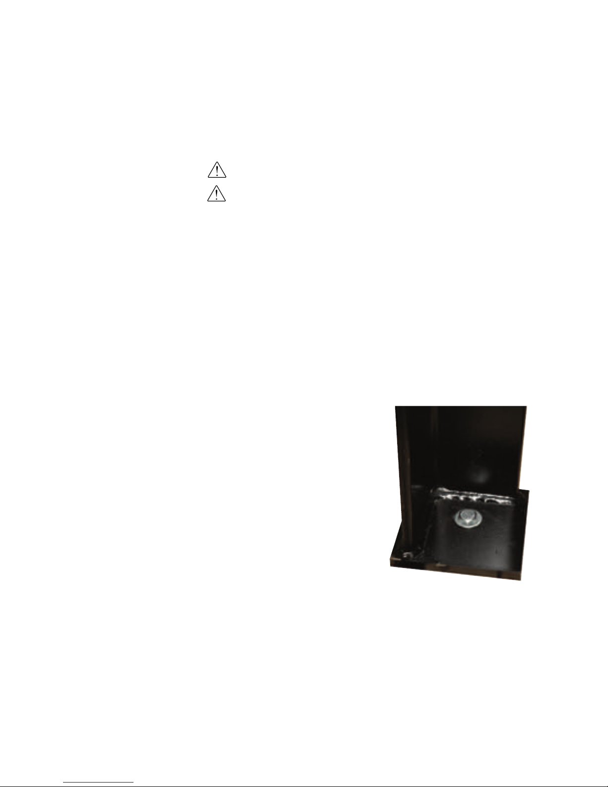
Securing the CH Hopper to the
Floor
WARNING: You are responsible for the structural integrity of this installation.
IMPORTANT: Fasten the CH Hopper floor stand to a rigid floor structure. This will
add rigidity to the installation and help to prevent accidents during operation and
maintenance of the CH Hopper.
Due to the varying size of Conair CH Hoppers, Conair recommends:
• Following all applicable local building and safety codes
• Using anchoring techniques and hardware suitable for the size and weight of a
fully loaded CH Hopper. See Description section entitled, Specifications: CH
Series Insulated Hoppers.
1 Secure the floor stand to the floor; following all applicable building and
safety codes.
✐
NOTE: The footpads on the floor
stand have existing holes that
can be used for anchoring the
floor stand depending on the
local building and safety codes.
3- 2 6 l I ns ta ll a ti on - Ge ne r al
Page 57

3
In s tal l a tio n
Location and Mounting of the
GasTrac Heater (i f equipped)
The GasTrac supplied with the EnergySmart Dryer System is designed to be
mounted to the floor near the CH Hopper air inlet.
1 Using a forklift, hoist or crane, move the GasTrac to its installation
location near the air inlet of the CH Hopper.
CAUTION: To prevent accident and injury, move the GasTrac to its location by using
a forklift, hoist or crane.
2 Position the GasTrac so that the gas, main power supply and exhaust flue
can be connected easily.
IMPORTANT: You will need to consider the location of the CH Hopper’s delivery air
inlet and the dryer installation location to properly install the GasTrac.
3 Secure the GasTrac to the mounting location floor using the holes in the
base of the GasTrac. Check to ensure that the mounting method meets all
local, regional and national codes and regulations.
NOTE: Electrical, control, air flow, gas and exhaust flue connections to the GasTrac will
be covered later in the installation process.
✐
In s ta ll at io n - Ge ne ra l l 3 -2 7
✐
NOTE: If your system has electrical heaters, for the drying system heat source, see Installation
section entitled, Location and
Mounting of the HTC.
Page 58

Location and Mounting of the Dust
Collector (op ti on al )
The optional dust collector that is used with your EnergySmart Dryer System is
designed to be mounted to the floor near the CH Hopper and optional integrated
cyclone.
To install the optional dust collector:
1 Using a forklift, hoist or crane, move the dust collector to its installation
location near the CH Hopper and optional integrated cyclone.
IMPORTANT: You will need to consider the installation of your entire dryer system
before permanently placing any system component.
CAUTION: To prevent accident and injury, move the dust collector to its mounting
location using a forklift, hoist or crane.
2 Secure the dust collector to the mounting location on the floor by using the
holes in the legs of the dust collector. Ensure that the mounting method meets
all local, regional and national codes and regulations.
(continued)
3- 2 8 l I ns ta ll a ti on - Ge ne r al
Inlet
Outlet
Page 59
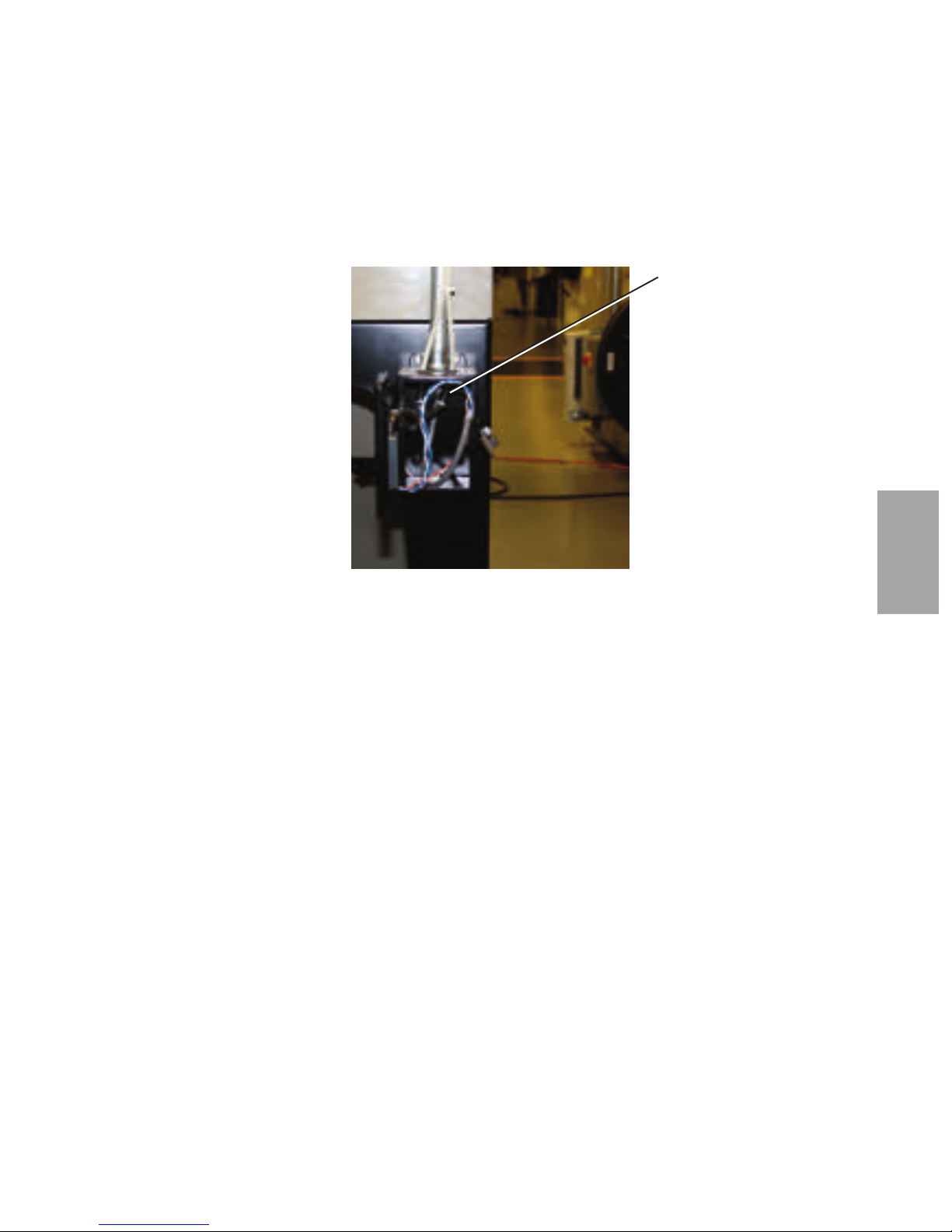
3
In s tal l a tio n
Location and Mounting of the Dust
Collector (op ti on al ) ( co nti nu ed)
3 Ensure that the hoses from the dif-
ferential pressure transmitter,
mounted to the dust collector leg,
have not become detached from the
dust collector's inlet and outlet tubes
during installation.
NOTE: Electrical, control and air flow
connections to the dust collector will
be covered later in the installation
process.
✐
NOTE: Dust collector shown with straight legs. Your EnergySmart
Dryer system will be supplied with dust collectors with “kick-out”
legs.
In s ta ll at io n - Ge ne ra l l 3 -2 9
Pressure
Differential
Transmitter
Page 60

Location and Mounting of the
Vacuum Pump(s) and Dust
Collector(s) ( opti o nal )
The optional vacuum pump(s) and associated dust collector(s) supplied with the
EnergySmart Dryer System are designed to be mounted to the floor and in any
convenient location near the CH Hopper.
1 Using a forklift, hoist or crane, move the vacuum pump(s) and associated
dust collector(s) to their installation location.
CAUTION: To prevent accident and injury, move the vacuum pump(s) and associated dust collector(s) to their locations by using a forklift, hoist or crane.
2 Position the equipment so that the main power supply, communication
cables and conveying lines can be connected easily.
IMPORTANT: You will need to consider the location of all EnergySmart Dryer
System components to properly install the vacuum pump(s) and associated dust
collector(s).
3 Secure the vacuum pump(s) and associated dust collector(s) to their
mounting locations on the floor by using the holes in the base of each
component. Ensure that the mounting method meets all local, regional and
national codes and regulations.
3- 3 0 l I ns ta ll a ti on - Ge ne r al
Page 61

Positioning the Dryer on the Floor
To position the dryer:
1 Lift the dryer from the shipping container using a fork truck.
2 Position the dryer on the floor near the CH Hopper. Make sure the location
allows easy connection to the heat source (HTC or GasTrac), water connections
and to the outlet of the optional dust collector.
Removing the Cable Tie from the
Desiccant Wheel (W 6 0 0 - 1000 m o dels)
The EnergySmart Dryer’s desiccant wheel cable tie must be removed while
installing the dryer.
To remove the cable tie:
1 Open the dryer side panels and remove the cable tie securing the desiccant
wheel, if it was not done while unpacking the dryer.
Installing the Regeneration
Exhaust Cover
The EnergySmart Dryer’s regeneration exhaust cover must be installed before
using the dryer.
To install the regeneration exhaust cover:
1 Remove the exhaust cover that is attached to the dryer’s shipping pallet.
2 Locate the bolt pattern on the top of the dryer, over top of the regeneration
exhaust outlet.
3 Position the regeneration exhaust cover over top of the regeneration
exhaust outlet, aligning both bolt patterns.
4 Secure the regeneration exhaust cover with supplied hardware, using an
appropriately-sized wrench.
✒
Desiccant Cable Tie
Regeneration
Exhaust Cover
In s ta ll at io n - Ge ne ra l l 3 -3 1
3
In s tal l a tio n
Page 62

Installing the Return Air Adapter
The EnergySmart Dryer’s return air adapter must be installed before using the
dryer.
To install the return air adapter:
1 Remove the return air adapter that is attached to the dryer’s shipping
pallet.
2 Locate the bolt pattern on the top of the dryer, over top of the return air
inlet.
3 Position the return air adapter over top of the return air inlet, aligning
both bolt patterns.
4 Secure the return air adapter with supplied hardware, using an
appropriately-sized wrench.
Return Air
Inlet Adapter
3- 3 2 l I ns ta ll a ti on - Ge ne r al
NOTE: If your system has hard piping, use the instructions in the next section.
✐
An optional hard piping kit for
your EnergySmart Dryer system
is available from Conair.
Contact Conair Parts
(800) 458 1960
From outside of the
United States, call:
(814) 437 6861
Page 63

3
In s tal l a tio n
Installing the Return Air Inlet and
Air Outlet Adapters (W1600 - 5000)
The EnergySmart Dryer’s return air inlet and air outlet adapters will be removed
when the dryer is shipped.
To install the return air inlet and air outlet adapters:
1 Remove the return air inlet and dry air outlet adapters that are attached to
the dryer’s shipping pallet.
2 Locate the bolt patterns on the top of the dryer, over top of the return air
inlet and dry air outlet.
3 Position the return air adapter over top of the return air inlet, aligning both
bolt patterns.
4 Secure the return air adapter with supplied hardware, using an
appropriately-sized wrench.
5 Position the dry air outlet adapter over top of the dry air outlet, aligning
both bolt patterns.
6 Secure the dry air outlet adapter with supplied hardware, using an
appropriately-sized wrench.
Dry Air
Outlet
Adapter
Return Air
Inlet Adapter
NOTE: An optional hard piping kit for your EnergySmart Dryer system is available from Conair.
Contact Conair Parts
(800) 458 1960
From outside of the
United States, call:
(814) 437 6861
✐
In s ta ll at io n - Ge ne ra l l 3 -3 3
Page 64
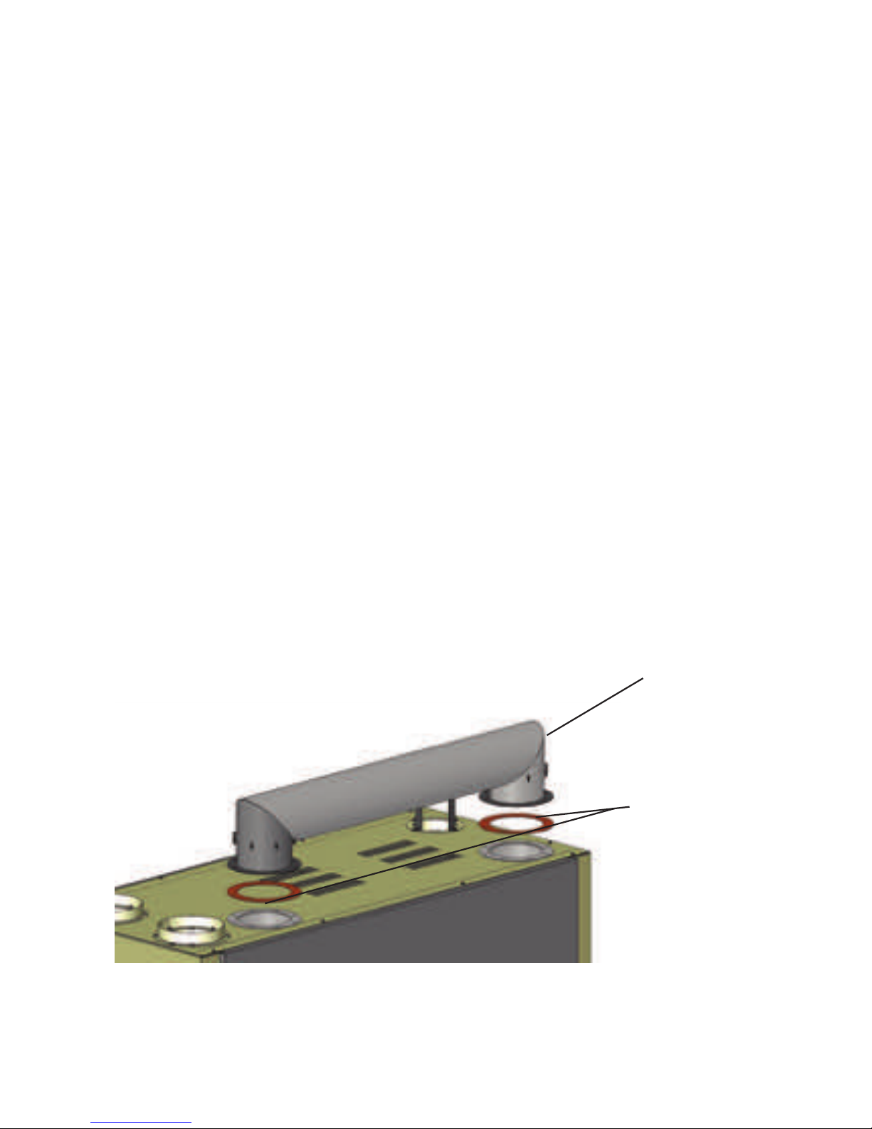
Installing the Overhead Process Air
Duct (W3200 - 5 0 0 0)
The EnergySmart Dryer’s overhead process air duct will be removed when the
dryer is shipped.
To install the overhead process air duct:
1 Remove the overhead process air duct that is attached to the dryer’s ship-
ping pallet. The piping will be shipped as one unit with included gaskets (2).
2 Locate the bolt patterns on the top of the dryer, over top of the overhead
process air duct inlet and outlet.
3 Position the overhead process air duct over top of the overhead process air
duct inlet and outlet making sure to place supplied gaskets between the
overhead process air duct and the inlet and outlet of the dryer, align all bolt
patterns.
4 Secure the piping with supplied hardware, using an appropriately-sized
wrench.
Overhead Process Air
Duct
Gaskets (2)
3- 3 4 l I ns ta ll a ti on - Ge ne r al
Page 65

Installation - Hard Piping Kits
In s ta ll at io n - Pi pi ng / Ho se s l 3- 3 5
3
In s tal l a tio n
Page 66

Optional Hard Piping Kits
The following sections detail the pipe/hose connections between the components
of the EnergySmart Dryer System. The piping can consist of hard piping or flexible tubes.
Conair offers both 8 inch and 12 inch {203.2 and 304.8 mm}hard piping kits that
can be used for your EnergySmart Dryer System installation. For more information concerning hard piping kits, contact your Conair Representative.
3- 3 6 l I ns ta ll a ti on - Pi pi n g/ Ho se s
An optional hard piping kit for
your EnergySmart Dryer system
is available from Conair.
Contact Conair Parts
(800) 458 1960
From outside of the
United States, call:
(814) 437 6861
Page 67
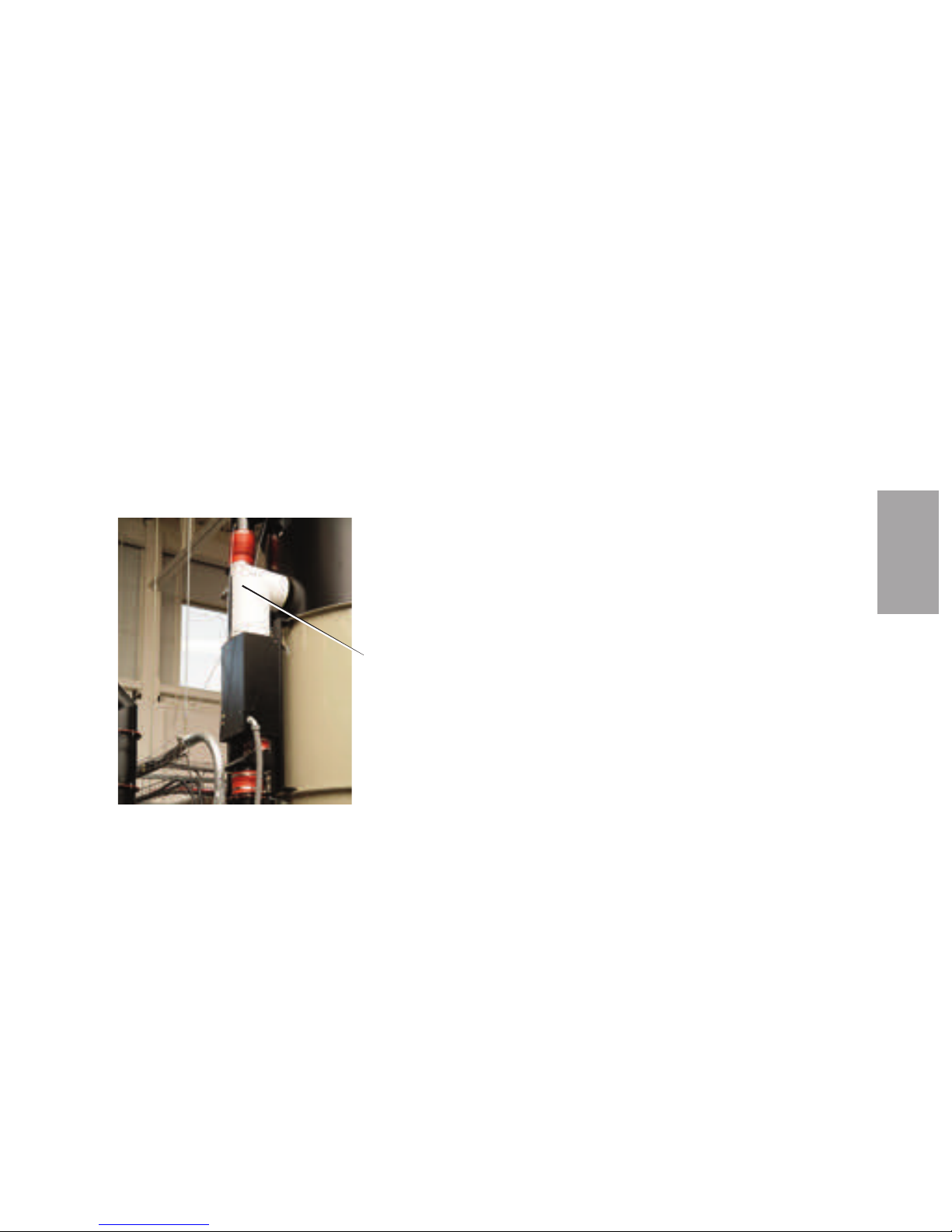
NOTE: Do not allow
the flexible hoses to
kink or crimp.
✐
Connecting the Heat Sources
Hoppe r Te mperature Co nt ro ller (HTC) as He at
Sourc e
NOTE: If your EnergySmart Dryer System was supplied with a GasTrac as the heat
source, see Installation section entitled, Connecting the Heat Sources, Gastrac Heat
Source.
1 Using insulated hard piping or flexible hose, connect the HTC outlet to
the air inlet of the CH Hopper. If flexible hose is used, make sure it is
securely clamped.
Make sure all hoses are securely clamped to
prevent wasteful leaking. The hoses should be
routed neatly and supported where possible to
prevent undue stress on the heater and hopper
assemblies. Also, the bends should be made
with gradual radiuses. Sharp turns will cause
undue pressure drops.
✐
HTC Outlet to CH
Hopper Inlet
Connection
In s ta ll at io n - Pi pi ng / Ho se s l 3- 3 7
3
In s tal l a tio n
(continued)
An optional hard piping kit for
your EnergySmart Dryer system
is available from Conair.
Contact Conair Parts
(800) 458 1960
From outside of the
United States, call:
(814) 437 6861
Page 68
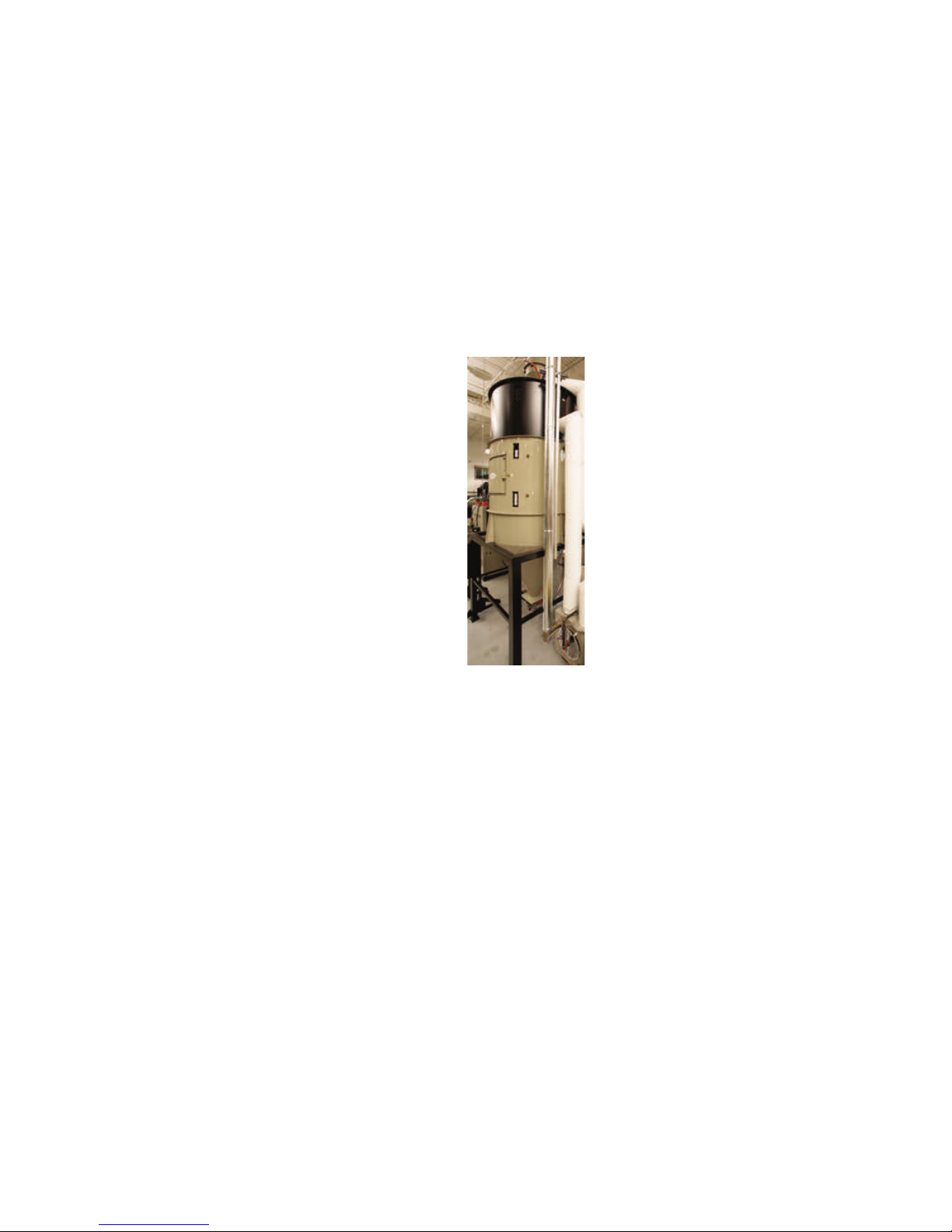
3- 3 8 l I ns ta ll a ti on - Pi pi n g/ Ho se s
Connecting the Heat Sources ( co nti nu ed)
GasTra c as Heat Sour ce
1 Using insulated hard piping or flexible hose, connect the GasTrac outlet to
the air inlet of the CH Hopper. If an insulated flexible hose is used, make sure
it is securely clamped.
Make sure all hoses are securely clamped to
prevent wasteful leaking. The hoses should be
routed neatly and supported where possible to
prevent undue stress on the heater and hopper
assemblies. Also, the bends should be made
with gradual radiuses. Sharp turns will cause
undue pressure drops.
NOTE: Do not allow
the flexible hoses to
kink or crimp.
✐
An optional hard piping kit for
your EnergySmart Dryer system
is available from Conair.
Contact Conair Parts
(800) 458 1960
From outside of the
United States, call:
(814) 437 6861
Page 69

Connecting the Dryer to the Heat
Source
1 Using hard piping or flexible hose, connect the delivery air outlet to the
inlet of the HTC or GasTrac. If a flexible hose is used, make sure it is
securely clamped.
Make sure all hoses are securely clamped to
prevent wasteful leaking. The hoses should be
routed neatly and supported where possible to
prevent undue stress on the heater and hopper
assemblies. Also, the bends should be made
with gradual radiuses. Sharp turns will cause
undue pressure drops.
In s ta ll at io n - Pi pi ng / Ho se s l 3- 3 9
(Dryer Connection to HTC Shown)
HTC Inlet
Dryer Outlet
NOTE: Do not allow
the flexible hoses to
kink or crimp.
✐
3
In s tal l a tio n
An optional hard piping kit for
your EnergySmart Dryer system
is available from Conair.
Contact Conair Parts
(800) 458 1960
From outside of the
United States, call:
(814) 437 6861
Page 70

Connecting the Dust Collector ( op tio na l)
1 Using uninsulated hard piping or flexible hose, connect the optional dust
collector outlet to the EnergrySmart Dryer return air inlet. If a flexible
hose is used, make sure it is securely clamped.
Make sure all hoses are securely clamped to
prevent wasteful leaking. The hoses should be
routed neatly and supported where possible to
prevent undue stress on the heater and hopper
assemblies. Also, the bends should be made
with gradual radiuses. Sharp turns will cause
undue pressure drops.
Dust
Collector
Outlet
Dryer
Inlet
NOTE: Do not allow
the flexible hoses to
kink or crimp.
✐
3- 4 0 l I ns ta ll a ti on - Pi pi n g/ Ho se s
An optional hard piping kit for
your EnergySmart Dryer system
is available from Conair.
Contact Conair Parts
(800) 458 1960
From outside of the
United States, call:
(814) 437 6861
Page 71
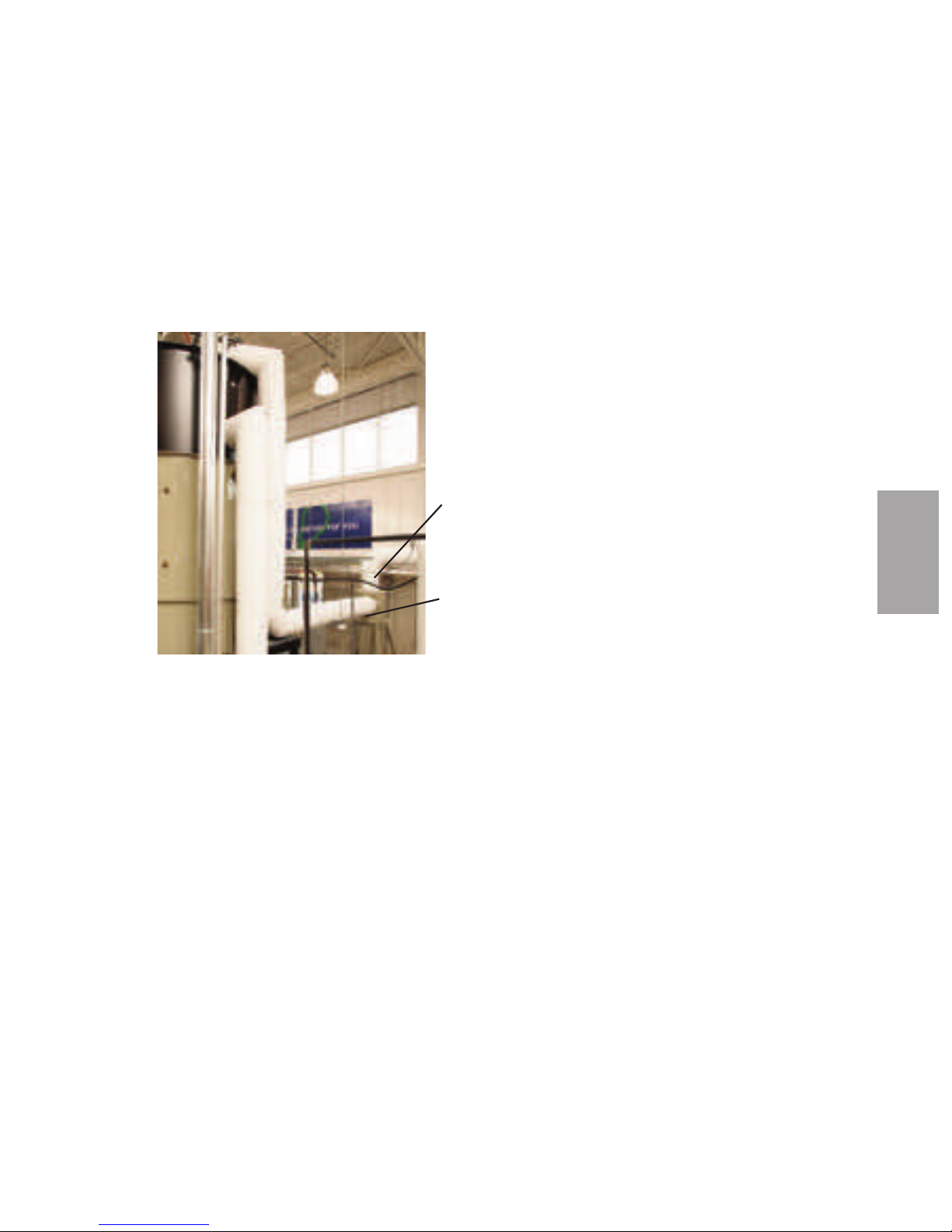
Connecting the Cyclone Separator
(o pt io na l)
1 Using uninsulated hard piping or flexible hose, connect the cyclone outlet
to the optional dust collector inlet or dryer return air inlet. If a flexible
hose is used, make sure it is securely clamped.
Make sure all hoses are securely clamped to
prevent wasteful leaking. The hoses should be
routed neatly and supported where possible to
prevent undue stress on the heater and hopper
assemblies. Also, the bends should be made
with gradual radiuses. Sharp turns will cause
undue pressure drops.
Outlet to
Dust
Collector
Inlet from
Cyclone
NOTE: Do not allow
the flexible hoses to
kink or crimp.
✐
3
In s tal l a tio n
In s ta ll at io n - Pi pi ng / Ho se s l 3- 4 1
An optional hard piping kit for
your EnergySmart Dryer system
is available from Conair.
Contact Conair Parts
(800) 458 1960
From outside of the
United States, call:
(814) 437 6861
Page 72

Installing the Dwyer 641 Air
Velocity Transmitter
The Dwyer 641 Air Velocity Transmitter (AVT) supplied with the EnergySmart
Dryer System should be installed within 8 or 12 in. {203.2 or 304.8 mm}
customer-supplied pipe using a 5/16 × 1/4 in. NPT compression fitting.
IMPORTANT: The AVT should be installed in a straight piece of pipe, on the
return air side of the EnergySmart Dryer. Conair recommends locating the
probe toward the end of long straight section of pipe to allow the air flow
as much length as possible to straighten out before it comes in contact
with the probe. Placing the probe too close to a transition or bend will
influence air flow readings.
To install the AVT:
1 Determine the best location to install the AVTs following the
recommendations above.
2 If Conair’s hard piping kit was not purchased with your system, drill and
tap customer-supplied 8 or 12 in. {203.2 or 304.8 mm} 2 ft. {0.6 m} long pipe
with a 7/16 in. drill bit and 1/4 in. - 18 NPT tap.
AVT in Dryer Return
Air Circuit (Shown
with hard piping kit)
(continued)
3- 4 2 l I ns ta ll a ti on - Pi pi n g/ Ho se s
NOTE: To order Conair's
optional hard piping kit for
your EnergySmart Dryer
System, contact your Conair
representative at: US 800458-1960, International
+1-814-437-6861.
✐
Page 73

Installing the Dwyer 641 Air
Velocity Transmitter (c on ti nu ed )
3 Screw the compression fitting into the customer-supplied pipe.
4 Orient the air velocity probe so that the flow direction arrow stamped on
the NUT used to secure the transmitter is pointing in the direction of the
air flow. The arrow is located on the nut below the conduit bodies.
5 Center in pipe. This will allow you to adjust the air velocity probe in the cen-
ter of the air stream.
Air Flow Direction
Arrows Located
on the Nut
3
In s tal l a tio n
In s ta ll at io n - Pi pi ng / Ho se s l 3- 4 3
NOTE: Refer to Dwyer 641
Instructions found in the
Appendix of this manual.
✐
Page 74

3- 4 4 l I ns ta ll a ti on - Pi pi n g/ Ho se s
Installing the Level Switch (o pti on al)
The level switch is installed on the side of the CH Hopper. The level switch’s
probe will be inserted through the hopper’s side wall at the customer desired level
to signal the dryer’s control to start a loading cycle to refill the hopper.
1 Remove the port plug at the material level that will start a loading cycle with
an appropriately-sized Allen wrench. Several port plugs are located along the
side of the CH Hopper.
2 Locate the level switch.
3 Apply Teflon tape to the installation threads of the level switch.
4 Insert the level switch into the material port selected in Step 1.
5 Install the level switch by rotating the probe and engaging the threads in
Step 3, using an appropriately-sized wrench.
6 Connect the wiring to the level switch as detailed in the supplied wiring
diagram.
Material Level Ports
Threads
CH Hopper
Wall
IMPORTANT: Always refer
to the wiring diagrams that
came with your level
switch before making
electrical connections.
(continued)
Page 75

3
In s tal l a tio n
In s ta ll at io n - Pi pi ng / Ho se s l 3- 4 5
Adjusting the Level Sensor (o pt ion al )
The level sensor should be adjusted both with ambient temperature and with operation temperature. Refer to the instruction manual that came with your level sensor
for further detail. To calibrate the unit:
1 Turn both the COARSE and FINE potentiometers fully counter-clockwise.
The COVERED internal indicator light should be off.
2 Turn the COARSE poten-
tiometer slowly clockwise to
the point where the COVERED indicator light just
turns on and says on.
3 Turn the FINE potentiometer
slowly clockwise until the
COVERED indicator light just
turns OFF. (If the course
potentiometer has been carefully
adjusted, this should occur when
the fine potentiometer is between
the 8 and 10 o’clock positions.)
Now continue to turn the FINE
potentiometer clockwise to the
desired sensitivity setting.
High sensitivity: 1/16 turn
Medium sensitivity: 1/8 turn
Low sensitivity: 1/4 to 1/2 turn
IMPORTANT: The calibration potentiometers are
delicate electronic devices.
Do not use excessive force
when adjusting.
NOTE: It may be convenient
to think of the FINE potentiometer as a clock face and
envision the distance between
consecutive hour numbers.
Turning the FINE potentiometer clockwise one hour position past the point at which
the covered indicator just
turns off would provide a high
sensitivity setting. Two hour
positions past that point
would provide a medium sensitivity setting.
✐
Page 76

3- 4 6 l I ns ta ll a ti on - Pi pi n g/ Ho se s
Installing the Process Protection
RTD Sensor
(H T C Onl y )
The process protection RTD probe is a safety sensor that prevents the HTC’s heater
from overheating in case of a process temperature sensor failure or insulated hose
failure.
The process protection RTD sensor senses the temperature leaving the heater
assembly to prevent damage to the process or the product within the CH Hopper. It
generates an alarm on the HTC control panel (A-49 or A-50) and shuts the heater
off if the air temperature exceeds the process protection setpoint. The element for
this sensor is to be mounted in the heater assembly outlet nozzle before the insulated hose is connected.
1 Insert the process protection RTD probe into the heater assembly outlet
nozzle. Center the end of the probe in the outlet so that the tip does not touch
the inlet tube walls.
2 Tighten compression fitting of the
probe to lock the RTD in place.
3 Route the process protection RTD
cable towards the location of the
HTC control panel.
Process
Protection RTD
Probe
Page 77

3
In s tal l a tio n
In s ta ll at io n - Pi pi ng / Ho se s l 3- 4 7
Location of the Process Material
Temperature Probe (RTD)
The EnergySmart Dryer control is configured to utilize data from an RTD probe,
located within your system, which senses the temperature of the process material
leaving the CH Hopper. However, the EnergySmart Dryer System does not provide a location for a material temperature probe. Therefore, the process material
temperature probe must be incorporated downstream of the CH Hopper and within
your delivery system.
Conair recommends that you check the throat of the machine to which your material is being delivered for an existing tap location that can be used to mount the
RTD. If none exists, a second option is to incorporate RTD mounting capabilities
into the piping/flange that will connect to the bottom of the CH Hopper after the
slide gate.
Conair recommends locating the RTD probe, when possible, within 30 ft {9.15 m}
of the EnergySmart Dryer.
NOTE: If the length of the supplied RTD cable is too short for your installation, route the
cable into a junction box then connect additional twisted pair wire cable of the appropriate length. Route the added cable to the EnergySmart Dryer control panel.
✐
Junction boxes are available
from Conair.
Contact Conair Parts
(800) 458 1960
From outside of the
United States, call:
(814) 437 6861
Page 78
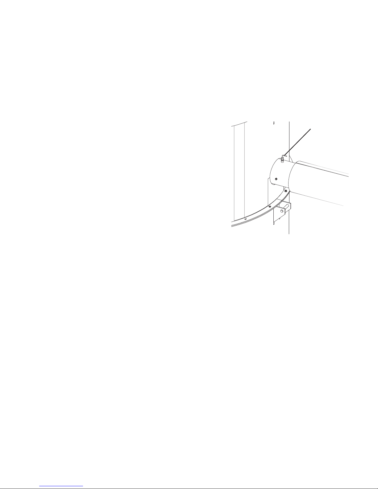
Installing the RTD Sensor
The RTD sensor monitors the temperature of the drying air as it enters the CH
Hopper. If the probe is not installed correctly, temperature readings will be inaccurate.
1 Insert the probe into the air inlet
port of the CH Hopper. The end
of the probe must not touch the
walls of the inlet pipe.
2 Tighten the compression fitting
to lock the RTD probe in place.
3 Route the GasTrac RTD cable
towards the location of the
GasTrac control panel.
RTD Probe
3- 4 8 l I ns ta ll a ti on - Pi pi n g/ Ho se s
Page 79

3
In s tal l a tio n
In s ta ll at io n - Pi pi ng / Ho se s l 3- 4 9
Installing the Return Air Dew Point
Line
The return air dew point line allows the dehumidifying dryer to monitor the moisture contained in the air leaving the CH Hopper via the dry air return port. If the
line is not installed correctly, dew point readings will be inaccurate.
1 Install the dew point line fitting
into the port located at the dry
air return circuit as it leaves the
CH hopper and before it enters
the optional cyclone.
2 Connect the supplied short (3 to
4 ft {0.9 to 1.2 m}) copper tube
to the dew point line fitting.
Route the copper tube down
towards the EnergySmart Dryer.
The copper tube is needed to dissi-
pate heat from the sample air.
3 Connect the supplied Teflon
®
tubing to the end of the copper
tube using the compression fitting supplied. Route the Teflon tubing towards
the Return Air Dew Point fitting on the back of
the
EnergySmart Dryer.
4 Cut the supplied Teflon tubing to the proper
length.
5 Connect the Teflon tubing to the Return Air
Dew Point fitting on the back of the
EnergySmart Dryer.
NOTE: The small fitting to the left of the Return
Air dew point fitting on the back of the dryer
allows the dew point to be checked with a hand
held device.
✐
Dew Point Line
Fitting
Page 80

3- 5 0 l I ns ta ll a ti on - Pi pi n g/ Ho se s
Page 81

3
In s tal l a tio n
Installation - Main Power
Connections
In s ta ll at io n - Ma in P ow er Con n ec ti on s l 3 -5 1
Page 82
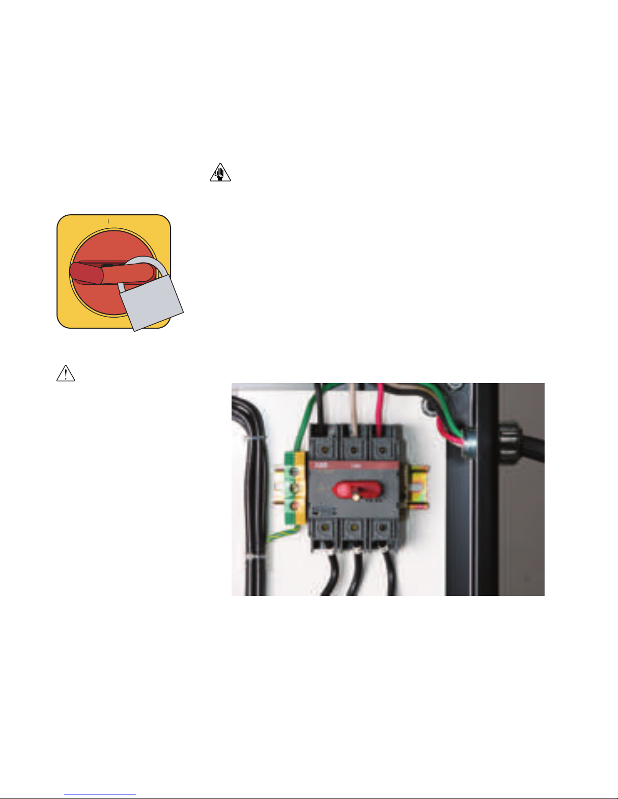
3- 5 2 l I ns ta ll a ti on - Ma in Po we r Co nn ec ti on s
Connecting Main Power to the
Dryer
CAUTION: Always disconnect and lock out the main power sources before making
electrical connections. Electrical connections should be made only by qualified
personnel.
1 Open the dryer’s electrical enclosure. Turn the disconnect dial on the dryer
door to the Off or “O” position. Turn the captive screw and swing the door open.
2 Insert the main power wire through the knockout in the side of the enclo-
sure or the rear of the dryer (the dryer’s electrical wire connection location
was a factory option and may be connected through the front or the rear of the
dryer). Secure the wire with an appropriately-sized strain relief.
3 Connect the power wires to the three (3) terminals at the top of the power
disconnect holder.
4 Connect the ground wire to the ground lug as shown in the photo.
IMPORTANT: Always refer
to the wiring diagrams
that came with your
EnergySmart Dryer before
making electrical
connections.
ON
O OFF
Page 83
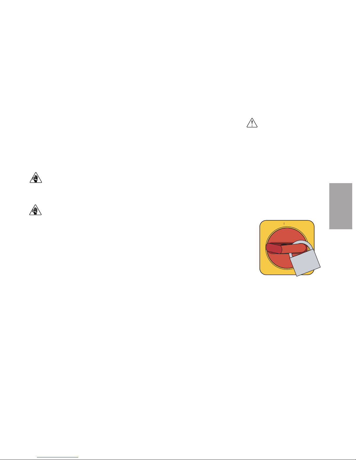
3
In s tal l a tio n
In s ta ll at io n - Ma in P ow er Con n ec ti on s l 3 -5 3
Connecting Main Power to the HTC
(Mode ls HT C 30, 60 , 9 0 a nd 120)
The electrical connection for the HTC models 30, 60, 90 and 120 only consists of
bringing power to the control center. The incoming power should match the rated
nameplate power required on the serial tag on the control center. See Description
section entitled, Specifications: Hopper Temperature Controller (HTC). This power
should be clean and have a voltage variation of no more than +/- 5% of the nameplate voltage. Unless the actual voltage is equal to the nameplate voltage, the actual
kW output of the HTC will vary slightly. The output varies with the square of the
voltage difference.
CAUTION: Always disconnect and lock out the main power sources before making
electrical connections. Electrical connections should be made only by a qualified
technician.
CAUTION: Check the disconnect with a volt meter to ensure that the power is off.
1 Disconnect and lock out the main power before making electrical connec-
tions. Electrical connections should be made only by a qualified technician.
2 Turn the disconnect dial on the control center door to the Off or “O”
position. Turn the captive screw and swing the control center door open.
3
Insert the main power
cable through a knockout in the side of the control center.
Secure the power cable with an appropriately-sized strain relief or use customersupplied conduit. Verify that the incoming power is securely attached to the control center and there is no strain on the incoming power.
4
Connect the power wires
to the three terminals at the top of the power disconnect
holder.
5 Connect the ground wire to the ground lug.
IMPORTANT: Always refer
to the wiring diagrams that
came with your HTC before
making electrical connections.
ON
O OFF
(continued)
Page 84

Connecting Main Power to the HTC
(c on ti nu ed )
(Mode ls HT C 180 and 27 0)
The electrical connection consists of bringing power into the control center and
wiring the power from the control center to the heater assembly. The incoming
power should match the rated nameplate power required on the serial tag on the control center. See Description section entitled, Specifications: Hopper Temperature
Controller (HTC). This power should be clean and have a voltage variation of no
more than +/- 5% of the nameplate voltage. Unless the actual voltage is equal to the
nameplate voltage, the actual kW output of the HTC will vary slightly. The output
varies with the square of the voltage difference.
CAUTION: Always disconnect and lock out the main power sources before making
electrical connections. Electrical connections should be made only by a qualified
technician.
CAUTION: Check the disconnect with a volt meter to ensure that the power is off.
1 Disconnect and lock out the main power before making electrical connec-
tions. Electrical connections should be made only by a qualified technician.
2 Turn the disconnect dial on the control center door to the Off or “O”
position. Turn the captive screw and swing the control center door open.
3
Insert the main power
cable through a knockout in the side of the control center.
Secure the power cable with an appropriately-sized strain relief or use customersupplied conduit. Verify that the incoming power is securely attached to the control center and there is no strain on the incoming power.
4
Connect the power wires
to the three terminals at the top of the power disconnect
holder.
5 Connect the ground wire to the ground lug.
NOTE: The connection between the heater and control center should be made with proper-
ly-sized conductors and protected with appropriate conduit (customer supplied). The routing should be neat and away from potential mechanical damage. The terminations should
be landed on the terminals in the control center and heater junction area. These terminations should be regularly checked to prevent loosening and shorting to ground.
3- 5 4 l I ns ta ll a ti on - Ma in Po we r Co nn ec ti on s
✐
IMPORTANT: Always refer
to the wiring diagrams that
came with your HTC before
making electrical connections.
ON
O OFF
(continued)
Page 85

3
In s tal l a tio n
In s ta ll at io n - Ma in P ow er Con n ec ti on s l 3 -5 5
Connecting Main Power to the HTC
(c on ti nu ed )
(Mode ls HT C 180 and 27 0) ( co nti nu ed )
6
Insert the customer-supplied heater power
wire through a knockout in the
side or bottom of the control center. Secure the wire with an appropriately-
sized strain relief, if conduit is not used.
7 Connect the heater power wires to the control center’s terminal block and
heater ground wire to the ground lug, as shown.
8
Insert the other end of heater power
wire through the knockout in the side
of the heater assembly. Secure the wire with an appropriately-sized strain
relief, if conduit is not used.
9 Connect the heater power wires to the top terminals of the heater assem-
bly’s terminal block and heater ground wires to the ground lug, as shown.
Power Wires
(Gray - Customer
Supplied)
Ground Wires
(Green - Customer
Supplied)
Ground Wires
(Green/Yellow)
Insert the Power
Wires Here
IMPORTANT: Always refer
to the wiring diagrams that
came with your HTC before
making electrical connections.
Page 86

3- 5 6 l I ns ta ll a ti on
Connecting Main Power to the
GasTrac
1 Open the GasTrac electrical enclosure. Turn the disconnect dial on the GasTrac’s
door to the Off or “O” position. Turn the captive screw, and swing the door open.
2 Insert the main power wire through
the knockout in the electrical enclosure. Secure the wire with an appro-
priately-sized relief.
3 Connect the power wires to the
three (3) terminals at the top of the
disconnect holder.
4 Connect the ground wire to either
grounding point shown in the diagram.
Honeywell
ESCSEL
IMPORTANT: Always refer
to the wiring diagrams
that came with the
GasTrac before making
electrical connections.
CAUTION: Electrical Hazard. Always disconnect and lock out the main power
sources before making electrical connections. Electrical connections should be
made only by qualified personnel.
ON
O OFF
Page 87

3
In s tal l a tio n
In s ta ll at io n l 3 -5 7
Connecting Main Power to the
Vacuum Pump(s) (o pt io na l)
1 Connect power. Refer to the accompanying wiring diagram for connection of
the main power supply. IMPORTANT: You must provide a wall-mounted
disconnect for three-phase electrical connection. Incoming voltage and
current must match the electrical specifications on the pump data plate
and serial tag.
WARNING: This equipment should be installed, adjusted, and serviced by qualified
technical personnel who are familiar with the construction, operation and potential
hazards of this type of machine. All wiring, disconnects and fuses should be installed
by qualified electrical technicians in accordance with electrical codes in your region.
Always maintain a safe ground. Do not operate the equipment at power levels other
than what is specified on the the machine serial tag and data plate.
2 Check for proper rotation of the pump after power has been connected
and before operation.
Connecting Main Power to the Dust
Collector(s)
(o pt io na l)
Proper operation of the optional dust collector depends upon its internal vacuum
valve opening whenever the vacuum pump is energized. Electrical connections are
provided by a 3-conductor cable connected to the dust collector. This cable should
be connected to the vacuum pump control enclosure to provide simultaneous operation of the dust collector when the pump is activated. On automatic unload/reload
dust collectors, the cable is attached to the reload control enclosure, which distributes power to the various solenoids for the auto reload function of the dust collector.
IMPORTANT: Always refer
to the wiring diagrams
that came with the vacuum pump(s) before making
electrical connections.
IMPORTANT: Always refer
to the wiring diagrams
that came with the dust
collector(s) before making
electrical connections.
Page 88

3- 5 8 l I ns ta ll a ti on - Pi pi n g/ Ho se s
Page 89

3
In s tal l a tio n
In s ta ll at io n - Ma in P ow er Con n ec ti on s l 3 -5 9
Installation - Conveying Lines
Page 90

3- 6 0 l I ns ta ll a ti on - Ma in Po we r Co nn ec ti on s
Connecting the Conveying Lines to
the Receiver(s) (o pt io na l)
If an optional receiver is mounted to the top of the CH Hopper, follow the instructions supplied with the receiver to connect the conveying lines. Also refer to the
receiver's installation instructions and operations manual for power, level switch
and compressed air connections/specifications.
If a secondary optional receiver is to be used, follow the instructions supplied with
the receiver to connect the conveying lines. Also refer to the receiver's installation
instructions and operations manual for power, level switch and compressed air
connections/specifications
Connecting the Conveying Lines to
the Purge Valv e(s) ( op ti on al)
If a purge valve is to be mounted to the bottom of the CH Hopper or auxiliary hopper follow the installation instructions, specifications, and wiring diagrams supplied with the valve. Also refer to the purge valve's installation instructions and
operations manual for power, compressed air connections/specifications.
Page 91
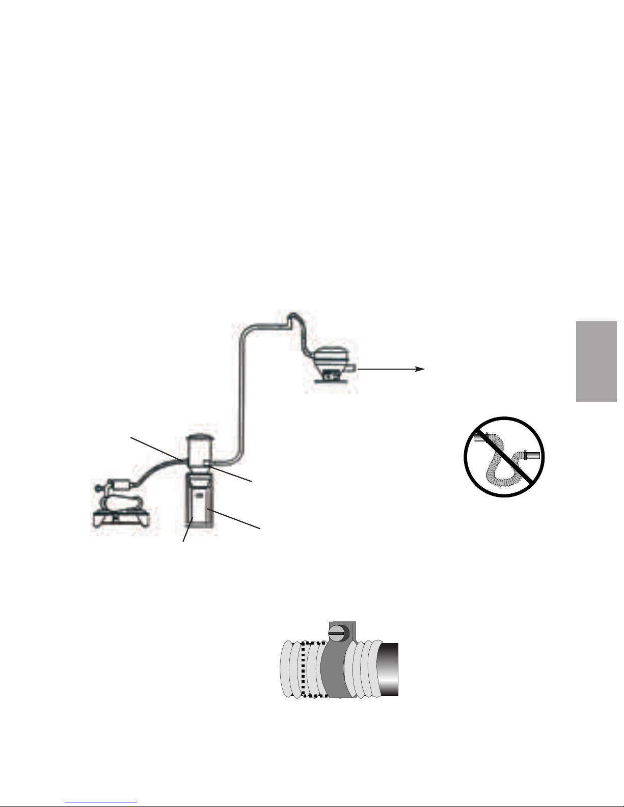
3
In s tal l a tio n
Connecting the Conveying Lines to
the Vacuum Pump(s) and Dust
Collector(s) ( op ti on al )
1 Connect the vacuum line from the optional receiver to the air inlet of the
optional dust collector.
2 Connect the vacuum line from the dust collector’s air outlet to the vacuum
pump’s air inlet.
3 Repeat Steps 1 and 2 if a second optional receiver, dust collector and vacu-
um pump are to be used.
Make sure all hoses are securely clamped to
prevent wasteful leaking. The hoses should be
routed neatly and supported where possible to
prevent undue stress. Also, the bends should
be made with gradual radiuses. Sharp turns
will cause undue pressure drops.
Air Inlet
Air Outlet
Collection Chamber
Floor Stand
To Material Supply
NOTE: Vacuum pump shown above is 180º out of position.
✐
NOTE: Do not allow
the flexible hoses to
kink or crimp.
✐
In s ta ll at io n - Ma in P ow er Con n ec ti on s l 3 -6 1
Page 92

3- 6 2 l I ns ta ll a ti on - Co nv e yi ng L in es
Page 93

Installation - Water Lines
3
In s tal l a tio n
In s ta ll at io n - W at er L in es l 3- 63
Page 94

BACK OF DRYER
WATER CONNECTION
**IT IS RECOMMEND THAT FLEX LINE BE USED TO
ALLOW FOR EASIER REMOVAL OF CONDENSER.
SEE INDIVIDUAL UNIT SPECIFICATION SHEET
FOR UNIT SPECIFIC SIZES
CUSTOMER HARD PLUMB WATER CONNECTION
3- 6 4 l I ns ta ll a ti on - W a te r Lin e s
Typical Water Lines Installation
Drawing
Conair recommends providing
supply and return water
valves at this location.
Page 95

Recommended Water Flow Rates
Dryer Model gal./min. {liters/min.}
600 15 {56.8}
800 15 {56.8}
1000 20 {75.7}
1600 25 {94.6}
2400 25 {94.6}
3200 30 {113.6}
5000 30 {113.6}
3
In s tal l a tio n
In s ta ll at io n - W at er L in es l 3- 65
Connecting the Aftercooler/
Intercooler and Optional Precooler
(W6 0 0 - 1000)
The aftercooler and/or optional precooler require a source of city, tower, or chiller
water and a discharge or return line. You can use water at temperatures of 45 to
85°F {7 to 29°C}.
1 Connect the water supply line to
the aftercooler/intercooler or
precooler inlet. If a manual shut
off valve is used, it should be
mounted on the inlet line.
2 Connect the water discharge or
return line with the pressure
relief valve to the aftercooler/
intercooler or precooler outlet.
Use the bracket supplied to secure
the pressure relief valve to the
back of the dryer.
IMPORTANT: Turn the water off when the dryer is not in use to prevent
condensation.
Aftercooler/Intercooler Inlet
Aftercooler/Intercooler Outlet
✒
TIP: Make the water supply and dis-
charge / return connections with
flexible hoses at least 24 in.
(61 cm) long. This allows you to
easily remove the aftercooler/
intercooler assembly for cleaning.
✒
TIP: If an optional flow control is
also being installed with the aftercooler/intercooler, the manual shut
off valve should be installed on the
inlet line for the flow control.
NOTE: Models W600-1000
dryer aftercooler/intercooler
and dry air delivery configura-
tion shown. Location on larg-
er models are different. Refer
to the labeling on your dryer.
✐
Page 96
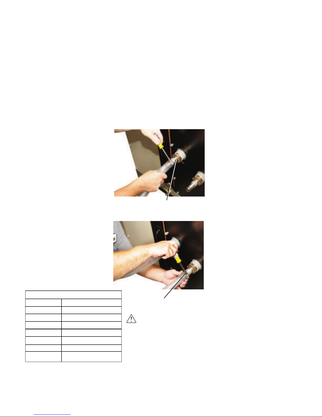
3- 6 6 l I ns ta ll a ti on - W a te r Lin e s
Connecting the Intercooler and
Optional Precooler (W1600 - 5 0 00)
The intercooler and/or optional precooler require a source of city, tower, or chiller
water and a discharge or return line. You can use water at temperatures of 45 to
85°F {7 to 29°C}.
1 Connect the water supply line to
the aftercooler/intercooler or
precooler inlet. If a manual shut
off valve is used, it should be
mounted on the inlet line.
2 Connect the water discharge or
return line with the pressure
relief valve to the aftercooler/
intercooler or precooler outlet.
Use the bracket supplied to secure
the pressure relief valve to the
back of the dryer.
IMPORTANT: Turn the water off when the dryer is not in use to
prevent condensation.
Aftercooler/Intercooler Inlet
Aftercooler/Intercooler Outlet
✒
TIP: Make the water supply and dis-
charge / return connections with
flexible hoses at least 24 in.
(61 cm) long. This allows you to
easily remove the aftercooler/
intercooler assembly for cleaning.
✒
TIP: If an optional flow control is
also being installed with the aftercooler/intercooler, the manual shut
off valve should be installed on the
inlet line for the flow control.
Recommended Water Flow Rates
Dryer Model gal./min. {liters/min.}
600 15 {56.8}
800 15 {56.8}
1000 20 {75.7}
1600 25 {94.6}
2400 25 {94.6}
3200 30 {113.6}
5000 30 {113.6}
Page 97

Installation - Control &
Communication Wiring
3
In s tal l a tio n
In s ta ll at io n - Co nt ro l & Co mm un i ca ti on W i ri ng l 3- 67
Page 98

Wiring the HTC (Electric Process
Heater) to the HTC Controller
IMPORTANT: Always refer to the proper wiring diagram supplied with your
equipment before making electrical connections.
CAUTION: Always disconnect and lock out the main power sources before
making electrical connections. Electrical connections should be made only by
qualified personnel.
1 Refer to the wiring diagram that came with your control.
2 Insert the control wires through a knockout in the side or bottom of the HTC
control center. Secure with a appropriately-sized strain relief, if conduit is not
used.
3 Connect the high temperature and pressure switch wires to the control
center's terminal block.
4 Insert the other end of the control wires through the knockout in one side of
the HTC heater assembly terminal box. Secure with a appropriately-sized strain
relief, if conduit is not used.
5 Connect the high temperature and pressure switch wires to the heater
assembly terminal block.
IMPORTANT: The connection between the heater and control center should
be made with customer supplied wire that has properly sized conductors
and properly protected with customer-supplied conduit. The routing should
be neat and away from potential mechanical damage. The terminations
should be landed on the terminals in the control center and heater junction
area. These terminations should be regularly checked to prevent loosening
and shorting to ground.
ON
O OFF
(continued)
3- 6 8 l I ns ta ll a ti on - Co nt r ol & Co mm u ni ca ti on Wi ri ng
IMPORTANT: Always refer
to the wiring diagram that
came with your HTC
before making electrical
connections.
Page 99
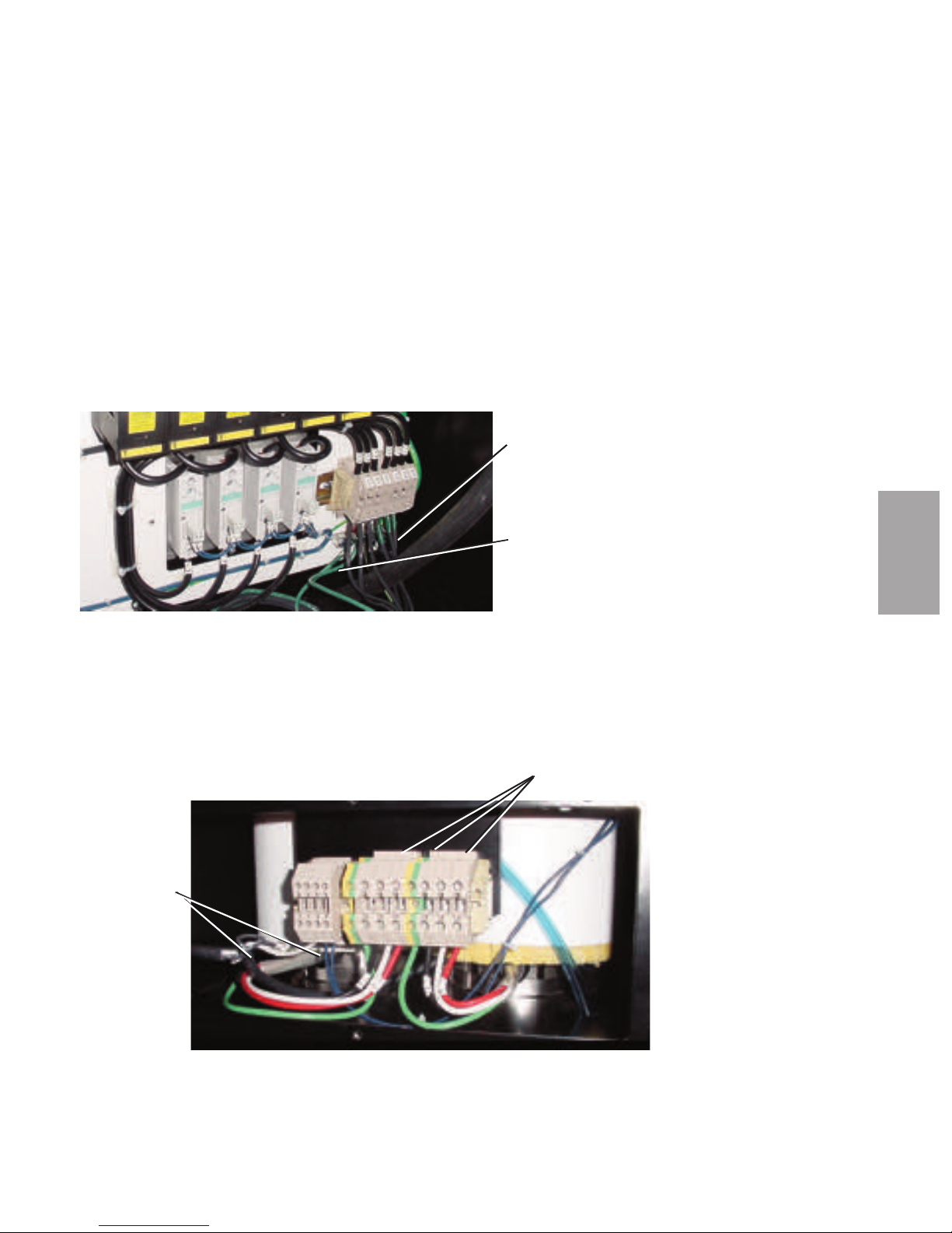
3
In s tal l a tio n
In s ta ll at io n - Co nt ro l & Co mm un i ca ti on W i ri ng l 3- 69
Connecting the HTC to the HTC
Controller ( co nt in ued )
6 Insert the heater power wire through a knockout in the side or bottom of
the HTC control center. Secure the wire with an appropriately-sized strain
relief, if conduit is not used.
7 Connect the heater power wires to the control center’s terminal block and
heater ground wire to the ground lug as shown.
8 Insert the other end of heater power wire through the knockout in the side
of the heater assembly. Secure the wire with an appropriately-sized strain
relief, if conduit is not used.
9 Connect the heater power wires to the top terminals of the heater assem-
bly’s terminal block and heater ground wires to the ground lug as shown.
Power Wires
(Customer
Supplied)
Ground WIres
(Green - Customer
Supplied)
Ground Wires
Green
Insert the Power Wires Here
Page 100
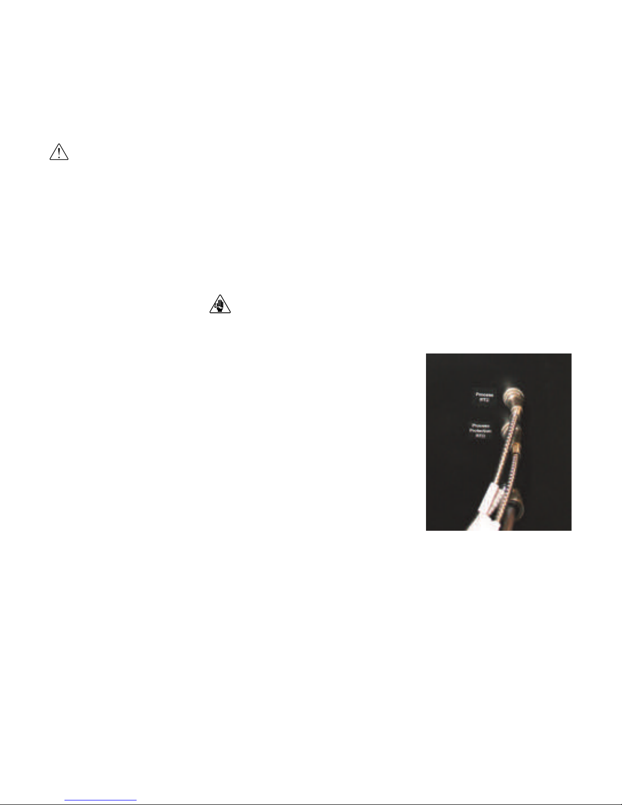
3- 7 0 l I ns ta ll a ti on - Co nt r ol & Co mm u ni ca ti on Wi ri ng
Connecting the RTD Sensors (HTC o nly )
The routing of the RTD sensor cables should be neat and not parallel with the
power connections. When a sensor cable must cross over power wiring, the intersection should be made at right angles (90 degree) to reduce the RFI noise transmitted to the sensor cable.
Pro ce ss Temperatur e RT D P ro be
The process RTD sensor connection should be made to the HTC’s control panel
CAUTION: Always disconnect and lock out the main power sources before making electrical connections. Electrical connections should be made only by qualified personnel.
1 Disconnect and/or lock out main power to
the HTC.
2 Route the process temperature RTD cable
from hopper inlet to the HTC’s control
panel. Plug the connector into receptacle in
the side of the control center labeled
“Process”. Hand tighten the connector. Coil
any excess cable and secure it with a wire tie.
Pro ce ss Pr otection RTD
Pro be
The process protection RTD probe is a safety sensor that prevents the HTC’s
heater from overheating in case of a process temperature sensor failure or insulated
hose failure.
The process protection RTD sensor senses the temperature leaving the heater
assembly to prevent damage to the process or the product in the CH Hopper. It
generates an alarm (A-49 or A-50) at the HTC control panel and shuts the heater
off if the air temperature exceeds the process protection setpoint. The element for
this sensor is to be mounted in the heater assembly outlet nozzle before the insulated hose is connected.
IMPORTANT: Always refer
to the wiring diagrams
that came with your HTC
before making electrical
connections.
(continued)
 Loading...