

Page 1
Belt Conveyor
Moducon series
Instant Access
Parts and Service
(800) 458-1960
(814) 437-6861
www.conairnet.com
The Conair Group, Inc.
One Conair Drive
Pittsburgh, PA 15202
Phone: (412) 312-6000
Fax: (412)-312-6227
UGR004/1200
Installation
Operation
Maintenance
Troubleshooting
Page 2
It is important to record the model and serial number(s) of
your equipment and the date you received it in the User
Guide. Our service department uses this information, along
with the manual number, to provide help for the specific
equipment you installed.
Keep this User Guide and all manuals, engineering prints and
parts lists together for documentation of your equipment.
Date:
Document Number: UGR004/1200
Serial number(s):
Model number(s):
Power Specifications:
Amps
Volts
Phase
Cycle
DISCLAIMER: The Conair Group, Inc., shall not be liable for errors
contained in this User Guide or for incidental, consequential damages in connection with the furnishing, performance or use of this
information. Conair makes no warranty of any kind with regard to
this information, including, but not limited to the implied warranties
of merchantability and fitness for a particular purpose.
Record your equipment’s
model and serial number(s) and the date you
received it in the spaces
provided.
Copyright 2000
All rights reserved
THE CONAIR GROUP, INC.
Page 3

UGR004/1200 Moducon Belt Conveyor
INTRODUCTION . . . . . . . . . . . . . . . . . . .1-1
Purpose of the User Guide . . . . . . . . . . . . . . . . . . . . . . . . .1-2
How the Guide is Organized . . . . . . . . . . . . . . . . . . . . . . .1-2
Your Responsibility as a User . . . . . . . . . . . . . . . . . . . . . .1-2
ATTENTION: Read this so no one gets hurt . . . . . . . . . . .1-3
DESCRIPTION . . . . . . . . . . . . . . . . . . . .2-1
What is the Belt Conveyor? . . . . . . . . . . . . . . . . . . . . . . . .2-2
Typical Applications . . . . . . . . . . . . . . . . . . . . . . . . . . . . .2-2
Belt Conveyor Features . . . . . . . . . . . . . . . . . . . . . . . . . . .2-3
Specifications . . . . . . . . . . . . . . . . . . . . . . . . . . . . . . . . . .2-4
Optional Equipment . . . . . . . . . . . . . . . . . . . . . . . . . . . . . .2-5
INSTALLATION . . . . . . . . . . . . . . . . . . . .3-1
Unpacking the Boxes . . . . . . . . . . . . . . . . . . . . . . . . . . . . .3-2
Preparing for Installation . . . . . . . . . . . . . . . . . . . . . . . . . .3-3
Positioning the Conveyor . . . . . . . . . . . . . . . . . . . . . . . . . .3-4
Setting the Height . . . . . . . . . . . . . . . . . . . . . . . . . . . . . . .3-4
Connecting the Main Power . . . . . . . . . . . . . . . . . . . . . . . .3-5
Adjusting the Conveyor Speed . . . . . . . . . . . . . . . . . . . . . .3-6
O
PERATION . . . . . . . . . . . . . . . . . . . . . .4-1
Control Features . . . . . . . . . . . . . . . . . . . . . . . . . . . . . . . .4-2
Starting the Conveyor . . . . . . . . . . . . . . . . . . . . . . . . . . . .4-2
Stopping the Conveyor . . . . . . . . . . . . . . . . . . . . . . . . . . . .4-3
M
AINTENANCE . . . . . . . . . . . . . . . . . . . .5-1
Preventive Maintenance Schedule . . . . . . . . . . . . . . . . . . .5-3
Checking Electrical Connections . . . . . . . . . . . . . . . . . . . .5-4
TROUBLESHOOTING
. . . . . . . . . . . . . . . .6-1
Before Beginning . . . . . . . . . . . . . . . . . . . . . . . . . . . . . . . .6-2
A Few Words of Caution . . . . . . . . . . . . . . . . . . . . . . . . . .6-2
Identifying the Cause of a Problem . . . . . . . . . . . . . . . . . .6-3
The Conveyor Does Not Move . . . . . . . . . . . . . . . . . . . . . .6-4
Movement is Wrong . . . . . . . . . . . . . . . . . . . . . . . . . . . . .6-5
APPENDIX
Appendix A: Customer Service . . . . . . . . . . . . . . . . . . . . .A-1
Appendix A: Guarantee/Warranty . . . . . . . . . . . . . . . . . . .A-2
Appendix B: AXU Series Control . . . . . . . . . . . . . . . . . . .B-1
PARTS/DIAGRAMS
i
TABLE OF
CONTENTS
Page 4

Page 5

1-1
UGR004/1200 Moducon Belt Conveyor
●●
Purpose of the User Guide . . . .1-2
●●
How the User Guide
is organized . . . . . . . . . . . . . . .1-2
●●
Your Responsibilities
as a User . . . . . . . . . . . . . . . .1-2
●●
ATTENTION: Read this so
no one gets hurt . . . . . . . . . . .1-3
INTRODUCTION
Page 6

Moducon Belt Conveyor UGR004/1200
1-2 INTRODUCTION
This User Guide describes the Conair Moducon Series Belt
Conveyors and explains step-by-step how to install, operate,
maintain and repair this equipment.
Before installing this product, please take a few moments to
read the User Guide and review the diagrams and safety information in the instruction packet. You also should review manuals covering associated equipment in your system. This
review won’t take long, and it could save you valuable installation and operating time later.
Symbols have been used to help organize the User Guide and
call your attention to important information regarding safe
installation and operation.
Symbols within triangles warn of conditions that could
be hazardous to users or could damage equipment.
Read and take precautions before proceeding.
Numbers within shaded squares indicate tasks or steps
to be performed by the user.
A diamond indicates the equipment’s response to an
action performed by the user.
An open box marks items in a checklist.
A shaded circle marks items in a list.
You must be familiar with all safety procedures concerning
installation, operation and maintenance of this equipment.
Responsible safety procedures include:
● Thorough review of this User Guide, paying particular
attention to hazard warnings, appendices and related diagrams.
● Thorough review of the equipment itself, with careful
attention to voltage sources, intended use and warning
labels.
● Thorough review of instruction manuals for associated
equipment.
● Step-by-step adherence to instructions outlined in this
User Guide.
PURPOSE OF
THE USER
GUIDE
HOW THE USER
GUIDE IS
O
RGANIZED
1
◆
❒
●
YOUR
RESPONSIBILITY
A
SAUSER
Page 7
WARNING: Improper installation,
operation, or servicing may result in
equipment damage or personal
injury.
This equipment should only be installed,
adjusted, and serviced by qualified technical
personnel who are familiar with the construction, operation, and potential hazards of this
type of machine.
All wiring, disconnects, and fuses should be
installed by qualified electrical technicians in
accordance with electrical codes in your
region. Always maintain a safe ground. Do not
operate the equipment at power levels other
than what is specified on the machine serial
plate.
INTRODUCTION 1-3
We design equipment with the user’s safety in mind. You can
avoid the potential hazards identified on this machine by following the procedures outlined below and elsewhere in the
User Guide.
ATTENTION:
READ THIS SO NO
ONE GETS HURT
UGR004/1200 Moducon Belt Conveyor
WARNING: Disconnect power
sources to prevent injury from
unexpected energization or startup.
This product has a moving belt. To prevent
possible injury from unexpected startup, always
disconnect and lockout the main power source
before performing maintenance or troubleshooting procedures on this product.
WARNING: Electrical Shock Hazard
This device must be properly grounded.
Improper grounding can result in severe
personal injury and erratic machine operation.
Do not operate the equipment at power levels
other than what is specified on the machine
serial plate.
Page 8

Page 9

2-1
UGR004/1200 Moducon Belt Conveyor
●●
What is the belt conveyor? . . . .2-2
●●
Typical applications . . . . . . . . . .2-2
●●
Conveyor features . . . . . . . . . . .2-3
●●
Specifications . . . . . . . . . . . . . .2-4
●●
Conveyor options . . . . . . . . . . . .2-5
DESCRIPTION
Page 10

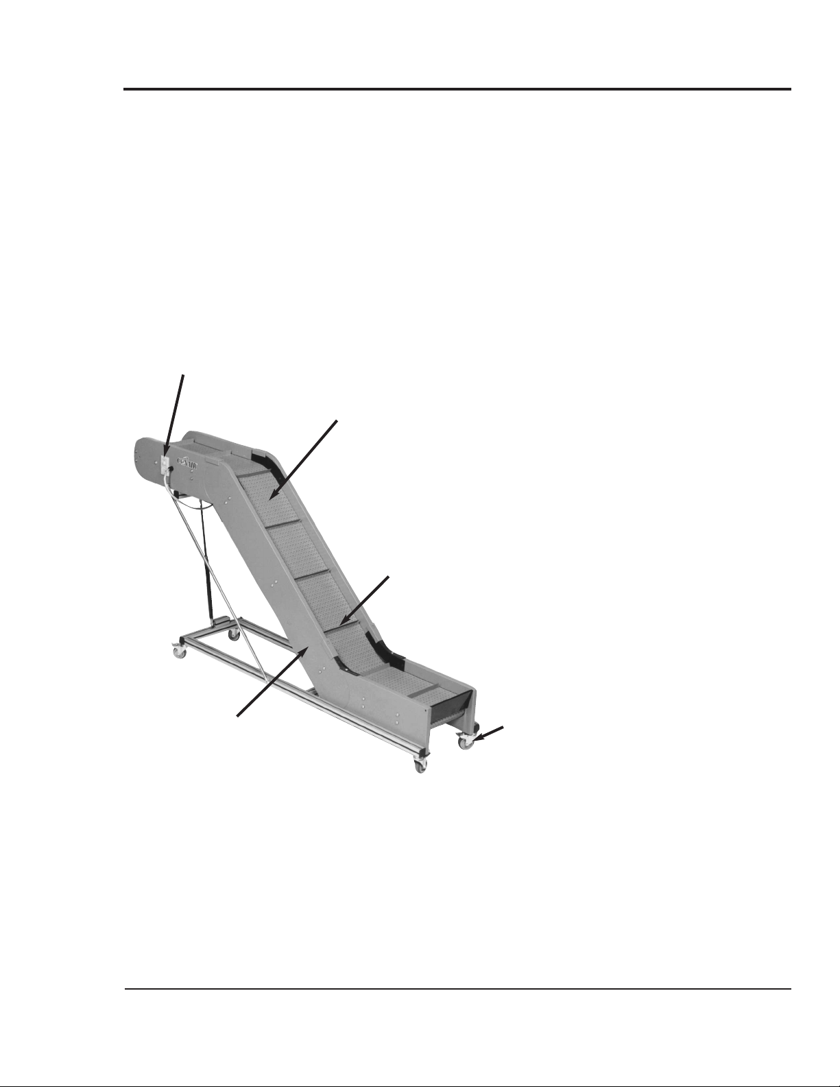
The Moducon Belt Conveyor is a lightweight, mobile conveyor that can be rolled into place and used to move parts or
materials to or from your process.
Because of its modular construction, the conveyor can be built
in virtually any shape, length and width to fit your
application.
Standard belt design is durable modular link polypropylene.
The patented design compensates for belt stretch that causes
slack, a common problem in other conveyor designs.
Permanent belt tracking ensures no wear on belt edges. The
belt system is easy to modify or repair by simply replacing
individual links or flights in the belt.
The Conair Belt Conveyor Moducon series is simple to operate. Just move it into position, adjust the height and plug it in.
The variable speed control lets you set the belt speed to the
desired rate. The optional flights move parts along the inclined
belt.
Moducon Belt Conveyors are ideal for:
● Conveying parts removed from a mold by a robot or
sprue picker.
● Carrying scrap or sprues to a granulator for recovery
● Conveying parts from the processing machine to an
assembly area.
As the application changes, the conveying length can be easily
modified by adding or subtracting side panels, belt links and
belt flights.
WHAT IS THE
BELT CONVEYOR?
Moducon Belt Conveyor UGR004/1200
2-2 DESCRIPTION
TYPICAL
APPLICATIONS
Page 11
UGR004/1200 Moducon Belt Conveyor
DESCRIPTION 2-3
BELT
CONVEYOR
FEATURES
Variable speed control
Allows you to operate at
variable speeds or indexing
to time the belt conveyor
with other auxiliary equipment.
Side walls
Low friction, replaceable
walls are available with optional
extensions that can be fitted to
either side of the conveyor.
Belt
Choose from the standard modular link
design or optional open or side-flexing
designs. The belts are available in:
● Polypropylene (standard)
● Acetal or polyamide (optional)
● Lengths from 3 to 15 feet in 1-foot
increments
● widths from 3 to 36 inches in 3-inch
increments
Steel casters
For easy mobility
(optional).
Flights
Set at regular intervals
move parts along the incline
at 1-, 2- and 3-inch intervals.
Modular construction allows the Moducon series conveyors to
be configured for almost any application. Conveyor types are:
● Flat
● Fixed angle
(30°, 45
°, and 60°)
● Adjustable angle
(0° to 45°), shown below
● Stepped
● 90° radius bend
Page 12

Moducon Belt Conveyor UGR004/1200
2-4 DESCRIPTION
SPECIFICATIONS
ADJUSTABLE ANGLE CONVEYOR
FLAT CONVEYOR
FIXED ANGLE CONVEYOR
STEPPED CONVEYOR
Conveyor length
Floor to belt height
Angle is
adjustable
from
5
° to 45°
Incline length 60 in.
{1500 mm} maximum
Horizontal length
Plastic side panel
Aluminum support frame
Plastic belt
Overall
width
Belt
width
Belt length
Height
above
belt
Height
below
belt
Support frame length
Plastic side panel
Aluminum support frame
Plastic belt
Overall
width
Belt
width
Conveyor length
Floor
to belt
height
Support frame length
Height
above
belt
Height
below
belt
Conveyor length
Floor
to belt
height
Incline length
Horizontal length
Plastic side panel
Aluminum support frame
Plastic belt
Overall
width
Belt
width
Height
above
belt
Height
below
belt
Support frame length
Conveyor length
Floor
to belt
height
Discharge
length
Incline
length
Horizontal
length
Plastic side panel
Aluminum support frame
Plastic belt
Overall
width
Belt
width
Height
above
belt
Height
below
belt
Support frame length
BELT CHARACTERISTICS Temperature Range Strength Hardness Wear Resistance Impact Resistance
BELT MATERIAL
Polypropylene (Standard) 34° - 218° F relatively low relatively low average low below 45° F
Acetal 40° -190° F very good very good average very good
Polyamide (Nylon) - 40° to 284° F excellent relatively high excellent low below -40° F
CONVEYOR TYPE FLAT STEPPED FIXED ANGLE ADJUSTABLE ANGLE
Performance characteristics
Inclines available — Fixed 30°, 45° or 60° Fixed 30°, 45° or 60° Adjustable 5° to 45°
Construction Aluminum frame; plastic sidewalls; plastic belt connector pins, standard; Stainless steel pins, optional
Belt materials Polypropylene, standard; Acetal or Polyamide (Nylon), optional
Belt type, 1-inch pitch Modular link designs, standard; Open or Side flexing designs, optional
Dimensions
Side wall height 2.4 in. {60 mm} above the belt; 4 in. {102 mm} or 8 inch {203 mm} with optional extensions
Belt width Specify desired width from 3 inches {76 mm} to 36 inches {915 mm} in 3-inch {76 mm} increments
Belt length Specify desired length from 3 feet {0.92 M} to 15 feet {5 M} in 12-inch {305 mm} increments
Floor to belt height Specify desired distance from floor to belt surface
Conveyor length Specify horizontal, incline and discharge lengths where applicable
Page 13

UGR004/1200 Moducon Belt Conveyor
DESCRIPTION 2-5
CONVEYOR
OPTIONS
Available options include:
● Belt types
Open belt - This belt has a 1-inch pitch
with an open design that allows faster
parts cooling. You can increase the cooling rate with optional fans mounted
beneath the belt. Belt widths start at 3
inches (76 mm) and increase in 3-inch increments to 36
inches (914 mm). All belt designs can be fitted with 1-, 2or 3-inch flights. The open belt is available in polypropylene, polyamide (nylon) and acetal. Choose color: blue,
gray, red, black or white.
Side flexing belt - this 1-inch pitch
side flexing belt has a turning inside
radius of 2.3 times the belt width. This
belt can be fitted with flights and rubber gripper sections. The side flexing belt material is
available in polypropylene, polyamide (nylon) and acetal.
Choose color: blue, gray, red, black or white.
●
Flights
Flights set at regular intervals in the belt
help hold the part in place on an incline or
decline of the conveyor. Optional flights
are available in heights of 1, 2 or 3 inches.
The application determines the distance between flights.
●
Side flexing units
Optional side flexing modules with a
90
°
bend can be added to flat or inclined
conveyors.
● Gripper sections
Optional grippers help hold the part in
place as it moves along the conveyor. The
rubber grip face is available on the side
flexing belt.
●
Bed plates
When conveying heavy products — weighing 11 lb
(5 kg) or more — bed plates can be added to provide
more support.
●
Stainless steel belt connector pins
When conveying heavy products, the optional stainless
steel connector pins provide better support than standard
plastic pins. Choose when the conveyor may be exposed
to moisture or water.
Page 14

Page 15

3-1
UGR004/1200 Moducon Belt Conveyor
●●
Unpacking the boxes . . . . . . . . .3-2
●●
Cautions and warnings . . . . . . .3-2
●●
Preparing for Installation . . . . . .3-3
●●
Positioning the Conveyor . . . . .3-4
●●
Setting the Height . . . . . . . . . . .3-4
●●
Connecting the Conveyor . . . . .3-5
●●
Adjusting the Conveyor . . . . . . .3-6
INSTALLATION
Page 16

The Moducon Belt Conveyor is shipped already assembled.
Carefully unpack the conveyor and its
components.
Remove all packing material, protective paper,
tape, and plastic. Compare contents to the shipping papers
to ensure that you have all the parts.
Carefully inspect all components to make sure
no damage occurred during shipping. If any damage is
found, notify the shipping agent immediately. Check all
wire terminal connections, bolts, and any other electrical
connections, which may have come loose during shipping.
Record serial numbers and specifications
in the blanks provided on the back of the User Guide's
title page. This information will be helpful if you ever
need service or parts.
Proceed to
P
REPARING FORINSTALLATION
.
UNPACKING
THE
BOXES
Moducon Belt Conveyor UGR004/1200
3-2 INSTALLATION
1
2
3
4
WARNING: Improper installation,
operation, or servicing may result in
equipment damage or personal
injury.
This equipment should only be installed,
adjusted, and serviced by qualified technical
personnel who are familiar with the construction, operation, and potential hazards of this
type of machine.
All wiring, disconnects, and fuses should be
installed by qualified electrical technicians in
accordance with electrical codes in your
region. Always maintain a safe ground. Do not
operate the equipment at power levels other
than what is specified on the machine serial
tag and data plate.
Page 17

UGR004/1200 Moducon Belt Conveyor
INSTALLATION 3-3
PREPARING FOR
INSTALLATION
Plan the location. Make sure the area where the belt conveyor
is installed has the following:
● A grounded power source. The belt conveyor
requires single phase, 100-115V, 50/60 Hz. All wiring
should be completed by qualified electrical technicians
and should comply with your region’s electrical codes.
● Clearance for safe operation and maintenance.
Make sure there is enough clearance around the conveyor for safe operation, maintenance and servicing.
We recommend maintaining at least 24 inches
(510mm) around all sides of the conveyor.
Perform the installation in the following order:
❒ Move the conveyor into position and adjust the level-
ing devices on the legs (or lock the optional casters).
❒ Adjust the height of the legs so that the conveyor belt
is at the proper height for your needs.
❒ Connect the conveyor to the power source.
❒ Adjust the belt speed.
24 inches
(610 mm)
24 inches
(610 mm)
24 inches
(610 mm)
24 inches
(610 mm)
Page 18

Moducon Belt Conveyor UGR004/1200
3-4 INSTALLATION
S
ETTING THE
H
EIGHT
POSITIONING
THE
CONVEYOR
Place the conveyor where it is needed, then verify that the
conveyor is level. If the conveyor is not level, adjust the
leveling devices on the legs. If your conveyor has the optional
casters, lock the casters in position.
Measure from the floor to the top of the conveyor belt. Adjust
the height of the belt by loosening the bolts on the legs and
sliding the conveyor up or down. Be sure to support the
conveyor while adjusting the bolts. Do not move the height
above the height of the leg frame.
Leg frame
Bolts
Belt
Leg frame
Side wall
Leg frame
Height adjustment
bolt above the belt
Belt
Leveling device
Height adjustment,
bolt below the belt
Page 19

UGR004/1200 Moducon Belt Conveyor
INSTALLATION 3-5
CONNECTING
MAIN POWER
WARNING: Disconnect power
sources to prevent injury from
unexpected energization or startup.
This product has a moving belt. To prevent
possible injury from unexpected startup, always
disconnect and lockout the main power source
before performing maintenance or troubleshooting procedures on this product.
WARNING: Improper installation,
operation, or servicing may result in
equipment damage or personal
injury.
This equipment should only be installed,
adjusted, and serviced by qualified technical
personnel who are familiar with the construction, operation, and potential hazards of this
type of machine.
All wiring, disconnects, and fuses should be
installed by qualified electrical technicians in
accordance with electrical codes in your
region. Always maintain a safe ground. Do not
operate the equipment at power levels other
than what is specified on the machine serial
tag and data plate.
Verify that the control button is set to Standby.
Plug the conveyor belt power cord into the
main power source supplying 100-115C/1 phase/50-60Hz.
1
2
Control button
Page 20

Moducon Belt Conveyor UGR004/1200
3-6 INSTALLATION
If the conveyor is not working properly at any time, slide the
control button to the Standby position immediately and unplug
the conveyor from the main power source. Refer to the
T
ROUBLESHOOTING
section of this User Guide.
If you do not encounter any problems during testing, proceed
to the
O
PERATION
section.
ADJUSTING THE
CONVEYOR
To adjust the speed of the conveyor belt:
Turn the speed control dial to Low.
If the speed is not set on Low, turn the dial counterclockwise as far as possible to the Low position. The belt
should not be moving.
Slide the control button to the Run position.
The conveyor belt begins to move.
Adjust the speed of the belt by turning the dial
clockwise until the belt is moving at the speed you want.
2
3
1
Dial
Turn clockwise to increase
belt speed. Turn counterclockwise to slow belt speed.
Control button
Page 21

4-1
UGR004/1200 Moducon Belt Conveyor
●●
Control features . . . . . . . . . . . . .4-2
●●
Before starting . . . . . . . . . . . . . .4-2
●●
Starting the belt conveyor . . . . .4-3
●●
Stopping the belt conveyor . . . .4-3
●●
Emergency stopping . . . . . . . . .4-3
OPERATION
Page 22

The belt conveyor control allows you to start, stop and control
the speed of the belt. Lights indicate when power is being
supplied to the unit and when an alarm condition exists.
CONTROL
FEATURES
Moducon Belt Conveyor UGR004/1200
4-2 OPERATION
S
TARTING THE
CONVEYOR
Make sure the conveyor is level and locked.
Adjust leveling feet as needed. Lock the optional casters.
Inspect the belt and mounting hardware.
Tighten any loose fittings or hardware. Replace any belt
links or flights that are worn, cracked or fractured.
Make sure the control button
in the Standby position.
Turn the speed control dial to Low.
Apply power to the conveyor.
Plug the power cord into the power source.
Slide the control button to the
Run position.
Adjust the belt speed as needed.
Turn the speed control dial clockwise to increase speed.
Turn the dial counterclockwise to decrease speed.
Indicator lights
display power on and
alarm conditions.
Dial
Turn clockwise to increase
belt speed. Turn counterclockwise to slow belt speed.
Control button
Slide left to Run position to
start belt movement.
Slide right to Standby to stop
the belt.
NOTE: The belt does not
move, but power to the the
conveyor is still on when the
unit is in Standby.
2
3
1
5
6
4
7
Page 23

UGR004/1200 Moducon Belt Conveyor
OPERATION 4-3
STOPPING THE
CONVEYOR
To stop the conveyor during operation:
Slide the control button to
the Standby position.
IMPORTANT: The Standby position is not a Power
OFF switch. When you want to stop the conveyor
motor for a long time, disconnect the conveyor from
the main power source.
To stop the conveyor for maintenance or repair:
Slide the control button to
the Standby position.
Disconnect the unit from the power source.
Remove the power plug from the electrical outlet. Follow
the lockout/tagout procedures developed in your facility to
ensure that power cannot be restored to the unit until the
maintenance or repair has been completed.
NOTE: Alarm conditions may stop the conveyor.
The conveyor will stop automatically under the following
alarm conditions:
● The load on the belt exceeds the rated torque
applied to the motor for more than 5 seconds.
The LED indicator light flashes and the motor stops.
● The motor cable or connector is disconnected.
The LED indicator light turns on and the motor stops.
● The motor speed exceeds 2800 rpm.
The LED indicator light turns on and the motor stops.
● Voltage applied to the control is 30% or more
below the the voltage setting.
The LED indicator light turns on and the motor stops.
2
1
1
Page 24

Page 25

5-1
UGR004/1200 Moducon Belt Conveyor
●●
Preventive Maintenance
Schedule . . . . . . . . . . . . . . . . .5-3
●●
Checking Electrical
Connections . . . . . . . . . . . . . .5-4
MAINTENANCE
Page 26

The Belt Conveyor Moducon series models need regular,
scheduled maintenance for peak performance.
Use the maintenance schedule on the following page as a
guide. You may need to shorten the time of the maintenance
schedule, depending on how often you use the conveyor.
Follow all safety procedures when working on the equipment.
PREVENTIVE
MAINTENANCE
SCHEDULE
Moducon Belt Conveyor UGR004/1200
5-2 MAINTENANCE
WARNING: Improper installation,
operation, or servicing may result in
equipment damage or personal
injury.
This equipment should be installed, adjusted,
and serviced only by qualified technical personnel who are familiar with the construction,
operation, and potential hazards of this type of
machine.
All wiring, disconnects, and fuses should be
installed and maintained by qualified electrical
technicians in accordance with electrical codes
in your region.
WARNING: Disconnect power
sources to prevent injury from
unexpected energization or startup.
This product has a moving belt. To prevent
possible injury from unexpected startup, always
disconnect and lockout the main power source
before performing maintenance or troubleshooting procedures on this product.
WARNING: Electrical Shock Hazard
This device must be properly grounded.
Improper grounding can result in severe
personal injury and erratic machine operation.
Do not operate the equipment at power levels
other than what is specified on the machine
serial plate.
Page 27

UGR004/1200 Moducon Belt Conveyor
MAINTENANCE 5-3
PREVENTIVE
MAINTENANCE
SCHEDULE
To maintain the best performance, follow this maintenance
schedule.
●●
Daily, or as needed
❒❒
Inspect leveling feet or casters.
Verify that conveyor is level. Adjust leveling feet as
needed. If the conveyor has optional casters, verify that
they are properly locked in position before operation.
●●
Monthly, or as needed
❒❒
Inspect the conveyor belt.
Check the belt links, pins and flights for wear, cracks
or fractures. Replace sections as needed.
❒❒
Inspect fittings and mounting hardware.
Make sure all fittings, screws, and component mounting hardware are tight. Tighten as needed.
❒❒
Inspect electrical connections.
Make sure all electrical terminals are tight. Adjust as
needed. See
C
HECKINGELECTRICAL
C
ONNECTIONS
, in
this section.
❒❒
Check all electrical cables.
Inspect all electrical cables for cuts and abrasions.
Replace as needed.
Page 28

Moducon Belt Conveyor UGR004/1200
5-4 MAINTENANCE
Be sure the main power is disconnected.
Always disconnect and lock out the main power source
before servicing the unit.
Inspect all wires and connections.
Look for loose wires, burned contacts, and signs of overheated wires. Have a qualified electrician make any necessary repairs or replacements.
Inspect the exterior power cord.
The cord should not be crimped, exposed, or rubbing
against the frame. If the cable runs along the floor, make
sure it is not positioned where it could rest in pooling
water or could be run over and cut by wheels or casters.
CHECKING
ELECTRICAL
CONNECTIONS
1
2
3
WARNING: Improper installation,
operation, or servicing may result in
equipment damage or personal
injury.
This equipment should be installed, adjusted,
and serviced only by qualified technical personnel who are familiar with the construction,
operation, and potential hazards of this type of
machine.
All wiring, disconnects, and fuses should be
installed and maintained by qualified electrical
technicians in accordance with electrical codes
in your region.
WARNING: Disconnect power
sources to prevent injury from
unexpected energization or startup.
To prevent possible injury from unexpected
startup, always disconnect and lock out the
main power source before performing maintenance or troubleshooting on this product.
WARNING: Electrical Shock Hazard
This device must be properly grounded.
Improper grounding can result in severe
personal injury and erratic machine operation.
Do not operate the equipment at power levels
other than what is specified on the machine
serial plate.
Page 29

6-1
UGR004/1200 Moducon Belt Conveyor
●●
Before Beginning . . . . . . . . . . . .6-2
●●
A Few Words of Caution . . . . . .6-2
●●
Identifying the
Cause of a Problem . . . . . . . . .6-3
●●
Answering an Alarm . . . . . . . . .6-3
●●
The Conveyor Does
Not Move . . . . . . . . . . . . . . . . .6-4
●●
Movement is Wrong . . . . . . . . . .6-5
TROUBLESHOOTING
Page 30

You can avoid most problems by following the recommended
installation, operation and maintenance procedures outlined in
this User Guide. If a problem should occur:
❒ Find any wiring, parts, and assembly diagrams that
were shipped with your equipment. These are the best
reference for correcting a problem. The diagrams will note
any custom features or options not covered in this User
Guide.
❒ Verify that you have all instructional materials related
to the conveyor and to any other equipment connected
to the system. Additional details about troubleshooting and
repairing specific components are found in these materials.
BEFORE
BEGINNING
Moducon Belt Conveyor UGR004/1200
6-2 TROUBLESHOOTING
A FEW WORDS
OF
CAUTION
WARNING: Improper installation,
operation, or servicing may result in
equipment damage or personal
injury.
This equipment should be installed, adjusted,
and serviced only by qualified technical personnel who are familiar with the construction,
operation, and potential hazards of this type of
machine.
All wiring, disconnects, and fuses should be
installed and maintained by qualified electrical
technicians in accordance with electrical codes
in your region.
WARNING: Disconnect power
sources to prevent injury from
unexpected energization or startup.
This product has a moving belt. To prevent
possible injury from unexpected startup, always
disconnect and lockout the main power source
before performing maintenance or troubleshooting procedures on this product.
WARNING: Electrical Shock Hazard
This device must be properly grounded.
Improper grounding can result in severe
personal injury and erratic machine operation.
Do not operate the equipment at power levels
other than what is specified on the machine
serial plate.
Page 31

IDENTIFYING THE
CAUSE OF A
PROBLEM
UGR004/1200 Moducon Belt Conveyor
TROUBLESHOOTING 6-3
The Troubleshooting section covers problems directly related
to the operation and maintenance of the belt conveyor.
This section does not provide solutions to problems that originate with other equipment. Additional troubleshooting help
can be found in manuals supplied with the other equipment.
The following alarm conditions will stop the belt conveyor
automatically:
● The load on the belt exceeds the rated torque applied
to the motor for more than 5 seconds.
The LED indicator light flashes and the motor stops.
● The motor cable or connector is disconnected.
The LED indicator light turns on and the motor stops.
● Motor speed exceeds 2800 rpm.
The LED indicator light turns on and the motor stops.
● Voltage applied to the control is 30% or more below the
the voltage setting.
The LED indicator light turns on and the motor stops.
When an alarm occurs during operation, the belt conveyor
stops. The belt will not move and the alarm light will continue
to flash or stay lit until the error is corrected.
Page 32

Moducon Belt Conveyor UGR004/1200
6-4 TROUBLESHOOTING
THE CONVEYOR
DOES NOT
MOVE
For additional information on problems that may have been
caused by the speed control unit, see
A
PPENDIX
B: AXU
S
ERIES
C
ONTROL
.
Symptom
The conveyor does
not move.
Possible cause
Electrical connections
are not correct.
The control button is in the
Standby position.
Both the clockwise and the
counterclockwise inputs are
turned on.
The speed setting potentiometer is not adjusted.
Load on belt exceeds rated
torque applied to the motor
for more than 5 seconds.
Motor speed exceeds
2800 rpm.
Voltage applied to the
control is 30% or more
below the voltage setting.
Solution
Check that:
❒ The conveyor is plugged into a
power source.
❒ The main power source is on.
❒ The interface cables are
connected.
❒ The fuses are good.
❒ The power to the conveyor is on.
Slide the control button to Run.
Turn off either the CW or the CCW
input. See
A
PPENDIX
B: AXU
S
ERIESCONTROL
.
Turn the speed setting potentiometer
slightly clockwise See
A
PPENDIX
B:
AXU S
ERIESCONTROL
.
Remove the excess load from the
belt.
Check voltage to motor. If incoming
voltage is wrong, connect to the
proper power source. If voltage is
correct, contact Conair Service.
Check voltage to motor. If incoming
voltage is wrong, connect to the
proper power source. If voltage is
correct, contact Conair Service.
Page 33

UGR004/1200 Moducon Belt Conveyor
TROUBLESHOOTING 6-5
Symptom
The motor turns
in the wrong
direction.
Motor operation is
unstable and
vibrating.
Possible cause
The clockwise input and
the counterclockwise input
are incorrect or electrical
connection is wrong.
The motor rotates in the
opposite direction depending on gearhead speed
reduction ratio.
The centerline is not
aligned between the motor
(gearhead) output shaft and
load shaft.
The motor and gearhead
are not assembled correctly.
Solution
Set the inputs to the correct
positions: when CW input is at
level L the motor shaft rotates
clockwise; when the CCW input
is at level L it rotates counterclockwise. See
A
PPENDIX
B:
AXU S
ERIESCONTROL
.
Reverse the CW and CCW input
operations. See
A
PPENDIX
B:
AXU S
ERIESCONTROL
.
Check the connection between
the motor (gearhead) output
shaft and the load shaft. See
A
PPENDIX
B: AXU S
ERIES
C
ONTROL
.
Check how the motor and gearhead are assembled. Check the
pinion shaft type. See
A
PPENDIX
B: AXU S
ERIESCONTROL
.
For additional information on problems that may have been
caused by the speed control unit, see
A
PPENDIX
B: AXU
S
ERIES
C
ONTROL
.
BELT MOTOR
MOVEMENT IS
WRONG
Page 34

Page 35

UGR004/1200 CUSTOMER SERVICE
APPENDIX A-1
Conair has made the largest investment in customer support in
the plastics industry. Our service experts are available to help
with any problem you might have installing and operating
your equipment. Your Conair sales representative also can help
analyze the nature of your problem, assuring that it did not
result from misapplication or improper use.
To contact Customer Service personnel, call:
From outside the United States, call: 814-437-6861
You can commission Conair service personnel to provide onsite service by contacting the Customer Service Department.
Standard rates include an on-site hourly rate, with a one-day
minimum plus expenses.
If you do have a problem, please complete the
following checklist before calling Conair:
❒ Make sure you have all model, serial and parts list numbers
for your particular equipment. Service personnel will need
this information to assist you.
❒ Make sure power is supplied to the equipment.
❒ Make sure that all connectors and wires within and between
the conveyor and related components have been installed
correctly.
❒ Check the troubleshooting guide of this manual for a solu-
tion.
❒ Thoroughly examine the instruction manual(s) for associat-
ed equipment, especially controls. Each manual may have
its own troubleshooting guide to help you.
❒ Check that the equipment has been operated as described in
this manual.
❒ Check accompanying schematic drawings for information
on special considerations.
BEFORE YOU
C
ALL ...
H
OW TO
C
ONTACT
C
USTOMER
SERVICE
Additional manuals and
prints for your Conair
equipment may be
ordered through the
Customer Service or
Parts Department for a
nominal fee.
WE’RE HERE
TO
HELP
Page 36

GUARANTEE/WARRANTY UGR004/1200
A-2
APPENDIX
EQUIPMENT
GUARANTEE
PERFORMANCE
WARRANTY
WARRANTY
LIMITATIONS
Conair guarantees the machinery and equipment on this order,
for a period as defined in the quotation from date of shipment,
against defects in material and workmanship under the normal
use and service for which it was recommended (except for
parts that are typically replaced after normal usage, such as
filters, liner plates, etc.). Conair’s guarantee is limited to
repairing or replacing, at our option, the part or parts determined by us to be defective after examination. The customer
assumes the cost of transportation of the part or parts to and
from the factory.
Conair warrants that this equipment will perform at or above
the ratings stated in specific quotations covering the equipment or as detailed in engineering specifications, provided the
equipment is applied, installed, operated and maintained in the
recommended manner as outlined in our quotation or specifications.
Should performance not meet warranted levels, Conair at its
discretion will exercise one of the following options:
● Inspect the equipment and perform alterations or adjust-
ments to satisfy performance claims. (Charges for such
inspections and corrections will be waived unless failure to
meet warranty is due to misapplication, improper installation, poor maintenance practices or improper operation.)
● Replace the original equipment with other Conair equip-
ment that will meet original performance claims at no extra
cost to the customer.
● Refund the invoiced cost to the customer. Credit is subject
to prior notice by the customer at which time a Return
Goods Authorization Number (RGA) will be issued by
Conair’s Service Department. Returned equipment must be
well crated and in proper operating condition, including all
parts. Returns must be prepaid.
Purchaser must notify Conair in writing of any claim and provide a customer receipt and other evidence that a claim is
being made.
Except for the Equipment Guarantee and Performance
Warranty stated above, Conair disclaims all other warranties with respect to the equipment, express or
implied, arising by operation of law, course of dealing,
usage of trade or otherwise, including but not limited to
the implied warranties of merchantability and fitness for
a particular purpose.
 Loading...