

Page 1

Sure Cut Rotary Knife Cutter
Instant Access
Parts and Service
(800) 458-1960
(814) 437-6861
www.conairnet.com
The Conair Group, Inc.
One Conair Drive
Pittsburgh, PA 15202
Phone: (412) 312-6000
Fax:(412)-312-6227
SC-5 Servo Model
UGE059/1003
Installation
Operation
Maintenance
Troubleshooting
Page 2

It is important to record the model and serial number(s) of
your equipment and the date you received it in the User
Guide. Our service department uses this information, along
with the manual number, to provide help for the specific
equipment you installed.
Keep this User Guide and all manuals, engineering prints and
parts lists together for documentation of your equipment.
Date:
Document Number: UGE059/1003
Serial number(s):
Model number(s):
Power Specifications:
Amps
Volts
Phase
Cycle
DISCLAIMER: The Conair Group, Inc., shall not be liable for errors
contained in this User Guide or for incidental, consequential damages in connection with the furnishing, performance or use of this
information. Conair makes no warranty of any kind with regard to
this information, including, but not limited to the implied warranties
of merchantability and fitness for a particular purpose.
Record your equipment’s
model and serial number(s) and the date you
received it in the spaces
provided.
Copyright 2003
All rights reserved
THE CONAIR GR OUP, INC.
Page 3

UGE059/1003 SC-5 SURE CUT Servo Knife Cutters
TABLE OF
CONTENTS
INTRODUCTION . . . . . . . . . . . . . . . . . . .1-1
Purpose of the User Guide . . . . . . . . . . . . . . . . . . . . . . . . .1-2
How the Guide is Organized . . . . . . . . . . . . . . . . . . . . . . .1-2
Your Responsibilities as a User . . . . . . . . . . . . . . . . . . . . .1-2
ATTENTION: Read this so no one gets hurt . . . . . . . . . . .1-3
How to Use the Lockout Device . . . . . . . . . . . . . . . . . . . .1-5
DESCRIPTION . . . . . . . . . . . . . . . . . . . .2-1
What is the SC-5 Sure Cut? . . . . . . . . . . . . . . . . . . . . . . . .2-2
Typical Applications . . . . . . . . . . . . . . . . . . . . . . . . . . . . .2-4
How the SC-5 Sure Cut Works . . . . . . . . . . . . . . . . . . . . . .2-5
SC-5 Sure Cut Features . . . . . . . . . . . . . . . . . . . . . . . . . . .2-7
Specifications . . . . . . . . . . . . . . . . . . . . . . . . . . . . . . . . . .2-7
Optional Equipment . . . . . . . . . . . . . . . . . . . . . . . . . . . . . .2-8
INSTALLATION . . . . . . . . . . . . . . . . . . . .3-1
Unpacking the Boxes . . . . . . . . . . . . . . . . . . . . . . . . . . . . .3-2
Preparing for Installation . . . . . . . . . . . . . . . . . . . . . . . . . .3-3
Positioning the SC-5 Sure Cut . . . . . . . . . . . . . . . . . . . . . .3-4
Connecting the Main Power Source . . . . . . . . . . . . . . . . . .3-6
Installing the Encoder . . . . . . . . . . . . . . . . . . . . . . . . . . . .3-7
Installing the Cutter Blades . . . . . . . . . . . . . . . . . . . . . . . .3-8
Mounting the Cutter Bushings . . . . . . . . . . . . . . . . . . . .3-10
Checking Repeatability . . . . . . . . . . . . . . . . . . . . . . . . . .3-12
Preparing for Testing . . . . . . . . . . . . . . . . . . . . . . . . . . . .3-13
Testing the Installation . . . . . . . . . . . . . . . . . . . . . . . . . . .3-13
OPERATION . . . . . . . . . . . . . . . . . . . . . .4-1
The Cutter Control Feature . . . . . . . . . . . . . . . . . . . . . . . .4-2
Before Starting . . . . . . . . . . . . . . . . . . . . . . . . . . . . . . . . .4-3
Powering Up . . . . . . . . . . . . . . . . . . . . . . . . . . . . . . . . . . .4-3
Main Screen . . . . . . . . . . . . . . . . . . . . . . . . . . . . . . . . . . .4-5
Preset to Run . . . . . . . . . . . . . . . . . . . . . . . . . . . . . . . . . .4-10
Time Preset . . . . . . . . . . . . . . . . . . . . . . . . . . . . . . . . . . .4-11
Cut Mode . . . . . . . . . . . . . . . . . . . . . . . . . . . . . . . . . . . . .4-18
Maintenance Area . . . . . . . . . . . . . . . . . . . . . . . . . . . . . .4-19
Encoder Area . . . . . . . . . . . . . . . . . . . . . . . . . . . . . . . . . .4-20
Unit of Measure . . . . . . . . . . . . . . . . . . . . . . . . . . . . . . . .4-22
Scale Distance . . . . . . . . . . . . . . . . . . . . . . . . . . . . . . . . .4-23
Homing . . . . . . . . . . . . . . . . . . . . . . . . . . . . . . . . . . . . . .4-25
Offset Example . . . . . . . . . . . . . . . . . . . . . . . . . . . . . . . .4-26
Preventative Maintenance . . . . . . . . . . . . . . . . . . . . . . . . .4-27
Power On Time . . . . . . . . . . . . . . . . . . . . . . . . . . . . . . . .4-28
Checking Cut Quality . . . . . . . . . . . . . . . . . . . . . . . . . . .4-29
Starting the SC-5 Sure Cut . . . . . . . . . . . . . . . . . . . . . . . .4-29
Making Adjustments During Operation . . . . . . . . . . . . . .4-30
Stopping the SC-5 Sure Cut . . . . . . . . . . . . . . . . . . . . . . .4-31
i
Page 4

SC-5 SURE CUT Servo Knife Cutter UGE059/1003
MAINTENANCE . . . . . . . . . . . . . . . . . . . .5-1
Maintenance Features . . . . . . . . . . . . . . . . . . . . . . . . . . . .5-2
Warnings and Cautions . . . . . . . . . . . . . . . . . . . . . . . . . . .5-2
Maintenance Overview . . . . . . . . . . . . . . . . . . . . . . . . . . .5-4
Preventative Maintenance Schedule . . . . . . . . . . . . . . . . . .5-4
Checking the Blades . . . . . . . . . . . . . . . . . . . . . . . . . . . . .5-6
Inspecting Cutter Bushing Screws . . . . . . . . . . . . . . . . . . .5-7
Checking the Closure Latch . . . . . . . . . . . . . . . . . . . . . . . .5-7
Cleaning the Blade Tray . . . . . . . . . . . . . . . . . . . . . . . . . .5-8
Lubricating the Slide Rail System . . . . . . . . . . . . . . . . . . .5-8
Adjusting the Proximity Switches . . . . . . . . . . . . . . . . . . .5-9
Checking Electrical Connections . . . . . . . . . . . . . . . . . . .5-10
B-Loc Installation and Removal . . . . . . . . . . . . . . . . . . . .5-12
TROUBLESHOOTING . . . . . . . . . . . . . . . .6-1
Before Beginning . . . . . . . . . . . . . . . . . . . . . . . . . . . . . . . .6-2
A Few Words of Caution . . . . . . . . . . . . . . . . . . . . . . . . . .6-2
Identify the Cause of a Problem . . . . . . . . . . . . . . . . . . . . .6-3
Electrical Problems . . . . . . . . . . . . . . . . . . . . . . . . . . . . . .6-4
Product Quality Problems . . . . . . . . . . . . . . . . . . . . . . . . .6-8
Replacing Safety and Proximity Switches . . . . . . . . . . . .6-12
Checking the Servo Amplifier . . . . . . . . . . . . . . . . . . . . .6-12
Adjusting the Proximity Switches . . . . . . . . . . . . . . . . . .6-14
Checking the Encoder . . . . . . . . . . . . . . . . . . . . . . . . . . .6-15
Checking the Motor/Reducer Assembly . . . . . . . . . . . . . .6-17
Checking Repeatability . . . . . . . . . . . . . . . . . . . . . . . . . .6-18
APPENDIX . . . . . . . . . . . . . . . . . . . . . . . . .
Customer Service Information . . . . . . . . . . . . . . . . . . . . . .A-1
Warranty Information . . . . . . . . . . . . . . . . . . . . . . . . . . . .A-2
Cutter Blade Selection and Use . . . . . . . . . . . . . . . . . . . . .B-1
Cutting Tips . . . . . . . . . . . . . . . . . . . . . . . . . . . . . . . . . . .B-3
Calculating Blade Interruption . . . . . . . . . . . . . . . . . . . . . .B-4
Conair Cutter Blades . . . . . . . . . . . . . . . . . . . . . . . . . . . . .B-6
All About Cutter Bushings . . . . . . . . . . . . . . . . . . . . . . . .C-1
Blade and Bushing Lubrication . . . . . . . . . . . . . . . . . . . . .D-1
Operator Display Overview . . . . . . . . . . . . . . . . . . . . . . . . E-1
P
ARTS/DIAGRAMS
This section has been provided for you to
store spare parts lists and diagrams.
ii
Page 5

1-1
UGE059/1003 SC-5 SURE CUT Servo Knife Cutter
●●
Purpose of the User Guide . . . .1-2
●●
How the User Guide
is organized . . . . . . . . . . . . . . .1-2
●●
Your Responsibilities
as a User . . . . . . . . . . . . . . . .1-2
●●
ATTENTION: Read this so
no one gets hurt . . . . . . . . . . .1-3
●●
How to Use the
Lockout Device . . . . . . . . . . . .1-5
INTRODUCTION
Page 6

SC-5 SURE CUT Servo Knife Cutter UGE059/1003
1-2 INTRODUCTION
This User Guide describes the Conair SC-5 Sure Cut Servo
Knife Cutter and explains step-by-step how to install, operate,
maintain and repair this equipment.
Before installing this product, please take a few moments to
read the User Guide and review the diagrams and safety information in the instruction packet. You also should review manuals covering associated equipment in your system. This
review won’t take long, and it could save you valuable installation and operating time later.
Symbols have been used to help organize the User Guide and
call your attention to important information regarding safe
installation and operation.
Symbols within triangles warn of conditions that could
be hazardous to users or could damage equipment.
Read and take precautions before proceeding.
Numbers within shaded squares indicate tasks or steps
to be performed by the user.
A diamond indicates the equipment’s response to an
action performed by the user.
An open box marks items in a checklist.
A shaded circle marks items in a list.
You must be familiar with all safety procedures concerning
installation, operation and maintenance of this equipment.
Responsible safety procedures include:
● Thorough review of this User Guide, paying particular
attention to hazard warnings, appendices and related diagrams.
● Thorough review of the equipment itself, with careful
attention to voltage sources, intended use and warning
labels.
● Thorough review of instruction manuals for associated
equipment.
● Step-by-step adherence to instructions outlined in this
User Guide.
PURPOSE OF
THE USER
GUIDE
HOW THE USER
GUIDE IS
O
RGANIZED
1
◆
❒
●
YOUR
RESPONSIBILITY
ASAUSER
Page 7

WARNING: Improper installation, operation, or servicing may result in
equipment damage or personal injury.
This equipment should only be installed, adjusted, and serviced by qualified technical personnel who are familiar with the construction, operation, and potential hazards of this type of
machine.
All wiring, disconnects, and fuses should be
installed by qualified electrical technicians in
accordance with electrical codes in your region.
Always maintain a safe ground. Do not operate
the equipment at power levels other than what
is specified on the machine serial plate.
INTRODUCTION 1-3
We design equipment with the user’s safety in mind. You can
avoid the potential hazards identified on this machine by following the procedures outlined below and elsewhere in the
User Guide.
ATTENTION:
READ THIS SO NO
ONE GETS HURT
UGE059/1003 SC-5 SURE CUT Servo Knife Cutter
DANGER: Sharp blades!
Most injuries caused by knife blades occur
when the cutter has been turned off. Handle
blades with care at all times.
● Always lock out the cutter before opening the
cutting chamber.
● Always wear cut-resistant gloves when the
cutting chamber is open and when handling
blades.
SC-5 cutters are equipped with several safety
devices to ensure safe operation. Never remove
or disable these devices to sustain production.
Operating without these devices can cause
severe injury.
● When the knife guard is opened, the knife
guard switch stops the cutter.
● Two proximity-type safety switches prevent
operation unless the cutter bushings are in
place.
● The STOP button activates a circuit that
stops the knife.(Do not attempt to change a
blade or work in the cutting chamber with out
locking out the power.
Page 8

In order to protect the operator from possible harm from the
rotating blade wheel, several safety features are built into this
cutter. They include:
Two electric switches make a contact between the side
and the clear polycarbonate sliding blade observation
windows such that the windows MUST BE CLOSED
in order to enable the blade wheel to spin.
●●
This prevents someone from opening the windows and
having the blade wheel spin which can cause serious
injury. Tampering with this safety feature will VOID
ANY responsibility for safety.
A proximity switch is positioned on both the upstream
and downstream side of the bushing holder. If there
are no bushings in either side, the blade will not spin.
●●
This prevents someone from inserting their hands or
fingers in the cutting mechanism while the blade wheel
is spinning. Tampering with this feature will also
VOID ANY responsibility for safety.
A safety switch is positioned on the bushing holder flip
up guard to prevent operation unless fully closed.
●●
This prevents someone from inserting their hands or
fingers in the cutting mechanism while the blade wheel
is spinning. Tampering with this feature will also
VOID ANY responsibility for safety.
A lockable main power disconnect is provided to pre-
vent the possibility of hazardous electrical shock while
servicing the main electrical enclosure. (See How to
use the Lockout Device, in Section 1)
SC-5 SURE CUT Servo Knife Cutter UGE059/1003
1-4 INTRODUCTION
WARNING:Voltage Hazard
This equipment is powered by three-phase
alternating current, as specified on the machine
serial tag and data plate.
A properly-sized conductive ground wire from
the incoming power supply must be connected
to the chassis ground terminal inside the electrical enclosure. Improper grounding can result in
severe personal injury and erratic machine
operation.
Always disconnect and lockout power before
opening the electrical enclosure or performing
non-routine procedures such as maintenance
and service.
ATTENTION:
READ THIS SO NO
ONE GETS HURT
CAUTION:It is always recommend
that the main power cord be disconnected and placed in clear view
of the operator or service personnel while changing blades or servicing the cutter in any capacity.
Page 9
HOW TO USE
THE
LOCKOUT
DEVICE
UGE059/1003 SC-5 SURE CUT Servo Knife Cutter
INTRODUCTION 1-5
WARNING: Electrical hazard
Before performing maintenance or repairs on
this product, disconnect and lock out electrical
power sources to prevent injur y from unexpected energization or start-up. A lockable device
has been provided to isolate this product from
potentially hazardous electricity.
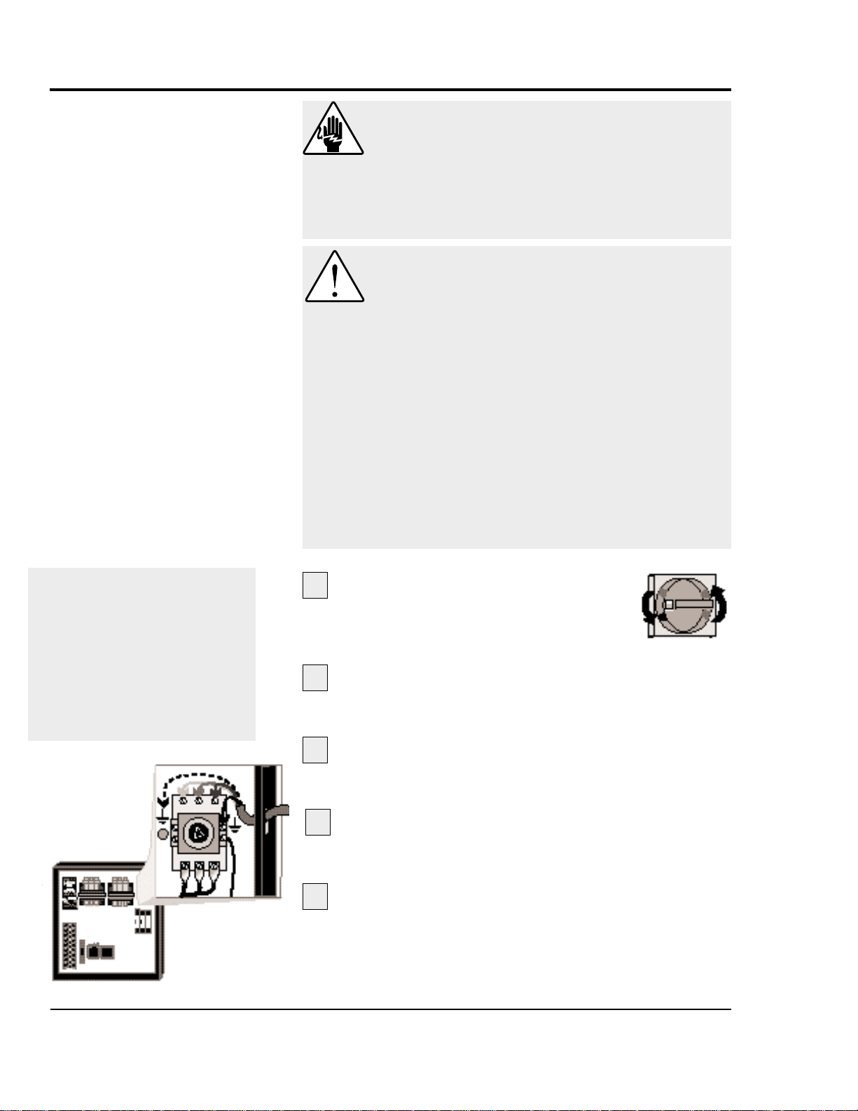
Lockout is the preferred method of isolating machines or
equipment from energy sources. Your Conair product is
equipped with the lockout device pictured below. To use the
lockout device:
Stop or turn off the equipment. Do not stop the
cutter by turning off the disconnect. Always touch the off
soft key on the interface first.
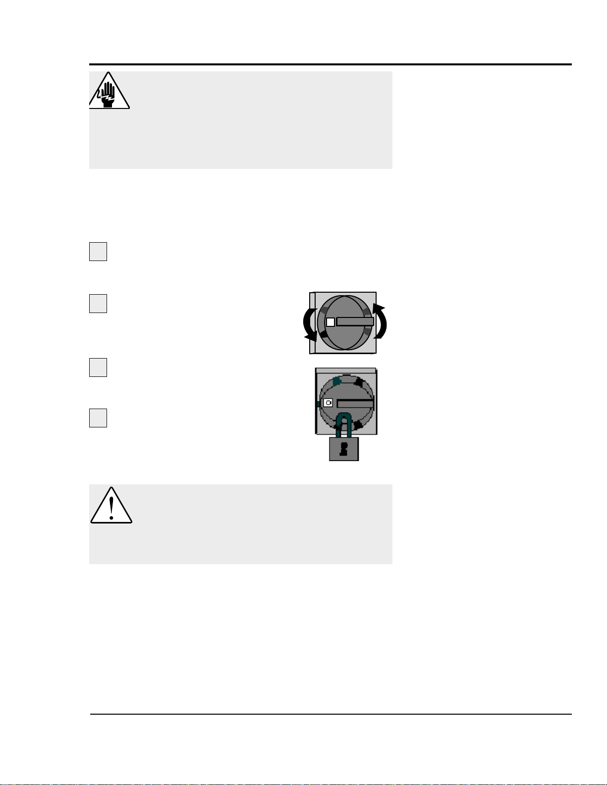
Isolate the equipment from
electrical power.
Turn the rotary disconnect switch to
OFF or O position.
Secure the device with an
assigned lock or tag.
The equipment is now locked
out.
CAUTION: Moving parts
Before removing lockout devices and returning
switches to the ON position, make sure that all
personnel are clear of the machine, tools have
been removed and all safety guards are reinstalled.
3
4
1
2
O
Page 10

Page 11

2-1
●●
What is the SC-5 Sure Cut
Knife Cutter . . .............2-2
●●
Typical Applications . . . .......2-4
●●
How the SC-5Works ...........2-5
●●
SC-5 Features . ...............2-7
●●
Specifications . ...............2-7
●●
Optional Equipment . . . . .......2-8
DESCRIPTION
UGE059/1003 SC-5 SURE CUT Servo Knife Cutter
Page 12

The Conair SC-5 Sure Cut Series rotary knife cutter has been
designed to be “The most versatile cutter of the industry”.
With both capacity to cut small parts at high speeds or large
tubes or profiles at low speeds this cutter can eliminate the
need for moving cutters in and out of a line per application.
Today with custom profile houses potentially running 2-3 different profiles on one line in a given day, time is at a premium. Having to move different cutters in and out of line is no
longer acceptable when time is money.
Mechanical Features
This series of servo rotary knife cutters use a 24 inch diameter
flywheel optimizing surface speed and power. This is in fact
the largest diameter wheel which could be used while still
allowing it’s mounting under the bushing holder.
Flywheel
With a 24 inch diameter flywheel which is 1inch thick, many
benefits become available.
Planetary Gear Reducer
A 10:1 in-line servo motor rated planetary gear reducer with 7
arc-minutes maximum backlash is mounted directly to a 3000
rpm brushless servomotor. A top flywheel speed of 300 rpm is
realized. Even though the flywheel appears to be moving
slowly, the actual surface speed at the blade at only 300
RPM’s is over 0.438 inch per millisecond. That’s twice the
surface speed of a typical clutch brake cutter.
Instead of mounting the cutter head directly to the servo motor
shaft, which is generally not designed for high radial load or
axial load due to small shaft diameters, the 24 inch flywheel is
mounted to the planetary gear reducer shaft which is designed
for just this type of application. At the gear ratio and output
speeds which this cutter was designed, radial load on the output shaft of the reducer is in excess of 1000 lbs where the
servo motor shaft may only be 100 lbs or less. Potential wear
on the servo motor shaft bearings is minimized.
The high speed\low torque power of the servo motor is efficiently converted into a low RPM\high surface speed\high
torque power more suitable for cutting applications.
WHAT IS THE
SC-5 SURE
CUT?
SC-5 SURE CUT Servo Knife Cutter UGE059/1003
2-2 DESCRIPTION
Continued
Page 13

W
HAT IS THE
SC-5 S
URE
CUT?
CONTINUED
DESCRIPTION 2-3
UGE059/1003 SC-5 SURE CUT Servo Knife Cutter
The larger diameter flywheel used on the servo cutter offers
the potential of higher surface speeds at dramatically lower
blade rpm’s with high cutting torque. The typical grey area
between on-demand cutting and flywheel cutting (150 cpm
on-demand up to 300 cpm flywheel), typically seen in DC driven clutch\brake cutter is eliminated.
It should not be necessary to cut in on demand mode in excess
of 150 cuts per minute which will greatly save on premature
wear to the system. Not only does this cutter offer optimum
blade surface speed throughout an extremely wide cuts per
minute range, but extreme accuracy throughout.
The added benefit of the 24 inch diameter by one inch thick
aluminum wheel is the stored inertia which adds power for
cutting larger profiles and tubes. The size of the wheel actually adds horsepower to the system. Due to the use of 10:1 gear
reduction, the servomotor is made extremely efficient and easily able to handle this weight with out detrimental effects.
Page 14

Cutting from Below the Bushing Holder
The SC-5 Sure Cut Servo Cutter housing maximizes versatility and operational ease. Due to the size of the flywheel it was
determined best to mount it directly below the bushing holder
keeping the center of gravity low and offering the following
benefits:
● Accessibility of the flywheel for ease of blade changes.
● Built in blade lubrication tray can be integral to the design
of the cutting chamber.
● An optional blade heating system can be added to give
optimum versatility to this cutter.
● With the bushing holder above the flywheel tremendous
cutting capacity is available without extreme blade length.
● Ease of discharge conveyor interface for part support and
automatic ejection systems is made simple with this layout.
● The optional slide system can enable the use of rigids and
flexibles.
To get the full benefit from the servo cutter Conair has provided several cutting modes, see Cutter Control, Section 4. The
Conair SC-5 Sure Cut servo rotary knife cutter is a truly innovative cutter. Loaded with features and backed up by the most
extensive service support system in the industry.
SC-5 SURE CUT Servo Knife Cutter UGE059/1003
2-4 DESCRIPTION
TYPICAL
APPLICATIONS
Page 15

Extruded material that has been sized and cooled enters the
cutter from the upstream side (See How the SC-5 Sure Cut
Works, Section 2, step 1). Typically, a puller is placed just
before the cutter; the puller pulls the extrudate through the
sizing and/or cooling tanks and feeds it into the cutter.
The positional servo motor, is direct coupled to the cutter
head, or an in-line planetary gear reducer that drives the cutter head. The planetary gear reducer arrangement increases
cutting torque, improves servo motor efficiency, and offers
improved bearing load ratings.
The cutting knife, attached to the cutter head, is driven by
the servo motor (See How the SC-5 Sure Cut Works, Section
2, step 2). Two cutter bushings guide and support both the
extrudate and the cutting knife. The cutter head is mounted
directly to the in-line planetary gear reducer shaft using a BLoc coupling device, and may have as many as four optional
blade positions. See Installation and Removal of B-Loc,
Section 5.
Two types of cutting modes are available. On-demand cutting modes (Timer, Encoder, Auto and Product) provide a
single rotation cut cycle. However, in continuous cutting
modes (Flywheel and Optional Follower) the cutting mechanism rotates continuously.
The knife guard includes a stainless steel lower tray, which
can be used for blade lubrication. The upper knife guard
includes a clear polycarbonate window. This allows you to
watch the cutting blade during operation.
Cut pieces are collected or carried on to further processing
by an optional conveyor (See How the SC-5 Sure Cut Works,
Section 2, step 3).
Continued on next page.
H
OW THE SC-5
S
URE CUT
WORKS
UGE059/1003 SC-5 SURE CUT Servo Knife Cutter
DESCRIPTION 2-5
Page 16

SC-5 SURE CUT Servo Knife Cutter UGE059/1003
2-6 DESCRIPTION
The cutter head holds the
blade(s) as they rotate
and pass between the
bushings, cutting the
extrudate.
Extruded material enters the
cutter from the upstream side.
1
Cut pieces are collected or
carried away on a conveyor.
2
3
HOW THE SC-5
S
URE CUT
WORKS
C
ONTINUED
Page 17

The SC-5 Sure Cut Servo Cutter features:
SC-5
F
EATURES
DESCRIPTION 2-7
UGE059/1003 SC-5 SURE CUT Servo Knife Cutter
Swivel Casters
Parts discharge chute or
optional discharge conveyor
Optional slide base
assembly with position
locking mechanism
Wide Range of Cutter
Bushing Capacities
24-inch diameter flywheel with multiple
blade mounting system
Polycarbonate blade
observation window
Optional blade
lubrication system
Heavy-duty leveling
screws and pads
The standard control:
● Large easy-to-read display.
● Soft keys allows the opera-
tor to select different functions.
● Numeric keys permits data
entry for the operator.
● Fixed function keys contain
universal symbols and text.
MODELS SC-5
Performance characteristics
Extruder capacity in. {mm}
Tube diameters 2.25 - 5.25 {57 - 133}
Profile dimensions 2x4 - 2x10, 4x7 {51x102 - 51x254, 102x178}
Blade drive motor Hp {kW} 4.6 {3.4}
Feed direction right>left
Dimensions in. {mm}
A - Height 47 {1194}
B - Height to centerline 40±2 {1016±50.8}
C - Length 44 {1118}
D - Width 52 {1321}
Voltage/phase/frequency 230 V/3/60 Hz 0r 460 V/3/60 Hz
Cutter control Red Lion {CL01/FM4}
A
B
C D
● 24-inch flywheel
● Up to 150 cuts/minute on
demand with one blade
● Up to 300 cuts/minute with one
blade on Flywheel mode
● Blade speeds adjustable to
300 RPM
● Surface speeds to 0.438 inches
per millisecond
● Heavy-duty positional AC
brushless servo drive
● 10:1 planetar y gear head
reducer
● 3,000 pulse bi-directional
encoder
S
PECIFICATIONS
CONAIR SERVO CUTTER
Version 1.0
Page 18

OPTIONAL
EQUIPMENT
SC-5 SURE CUT Servo Knife Cutter UGE059/1003
2-8 DESCRIPTION
Slide Base
This option is highly recommended for cutting flexible extrudates. While the cutter base is fixed and aligned with the
puller, the cutter itself is mounted on a set of linear slides that
allow as much as 12 inches of movement. The cutter can be
moved away from the puller for startup, then moved close to
the puller to enhance delivery to the cutter bushings.
Blade Wipe
The blade wipe system keeps the cutting blade clean by
removing lubricant and particles from the blade. A felt pad
sandwiched between two pieces of stainless steel and mounted
next to the bushing wipes the knife before each cut.
Custom Bushing Holder Sizes Available:
Heavy Duty Blade Positions
●●
One blade position standard
●●
Optional 2 or 4 blade positions available
●●
Optional simitare blade available (see parts list for optional
blades.)
Round Profile
2.25 inch (standard) 2x4 inch
3.25 inch 2x6 inch
4.25 inch 2x8 inch
5.25 inch 2x10 inch
3x6 inch
4x7 inch
Page 19

UGE059/1003 SC-5 SURE CUT Servo Knife Cutter
DESCRIPTION 2-9
TIP: Conair strongly recom-
mends the use of an isolation
transformer.Ensuring clean
and proper power can help
avoid the need for costly service calls.
Discharge Conveyor
A discharge conveyor facilitates the removal of cut parts.
Discharge conveyors are available in the following sizes:
● 6 inches wide by 6 feet long
● 6 inches wide by 10 feet long
● 6 inches wide by 16 feet long
Isolation Transformer
The isolation transformer protects sensitive electronics from
incoming power, which helps prevent errors caused by electrical noise. It also protects equipment from electrical noise generated by the servo motor and associated amplifier.
NOTE: An isolation transformer will not compensate for a
ground that does not meet code requirements.
Left to Right Machine Operation
This option changes the machine direction from the standard
right to left extrusion flow.
Special Paint Type or Color
This option covers any change from the standard Conair
paint.
Your Conair sales representative can analyze your needs and
recommend the options that are right for your system.
OPTIONAL
EQUIPMENT
Page 20

Page 21

3-1
UGE059/1003 SC-5 SURE CUT Servo Knife Cutter
●●
Unpacking the Boxes . . . . . . . . .3-2
●●
Preparing for Installation . . . . . .3-3
●●
Positioning the SC-5
Sure Cut . . . . . . . . . . . . . . . . .3-4
●●
Connecting the Main
Power Source . . . . . . . . . . . . .3-6
●●
Installing the Encoder . . . . . . . .3-7
●●
Installing the Cutter
Blades . . . . . . . . . . . . . . . . . . .3-8
●●
Mounting the Cutter
Bushings . . . . . . . . . . . . . . . .3-10
●●
Checking Repeatability . . . . . .3-12
●●
Preparing for Testing . . . . . . . .3-13
●●
Testing the Installation . . . . . . .3-13
INSTALLATION
Page 22

The SC-5 Sure Cut Series Servo Knife Cutter comes fully
assembled in a single crate.
UNPACKING THE
BOXES
SC-5 SURE CUT Servo Knife Cutter UGE059/1003
3-2 INSTALLATION
CAUTION: Lifting
To avoid personal injury or damage to the cutter, lift the cutter using a for klift or hoist with
straps that have been positioned at the cutter's
center of gravity.
Carefully uncrate the cutter and its components.
Remove all packing material
, protective paper,
tape, and plastic. Compare contents to the shipping papers
to ensure that you have all the parts.
Carefully inspect all components to make sure
no damage occurred during shipping. Check all wire terminal connections, bolts, and any other electrical connections, which may have come loose during shipping.
Record serial numbers and specifications in the
blanks provided on the back of the User Guide's title
page. This information will be helpful if you ever need
service or parts.
You are now ready to begin installation.
Complete the preparation steps in Preparing for
Installation, Section 3.
1
2
3
4
5
Page 23
You need these tools for installation:
❒ wire strain relief
❒ 16- or 18-inch adjustable wrench
❒ set of Allen wrenches
❒ set of feeler gauges
❒ ½ inch open or box end wrench
❒ flashlight
Plan the location. Make sure the area where the
servo cutter is installed has the following:
● A grounded power source. Check the cutter’s seri-
al tag for the correct amps, voltage, phase and
cycles. All wiring should be completed by qualified
personnel and should comply with your region’s
electrical codes.
● Clearance for safe operation and maintenance.
Make sure there is enough clearance around the
servo cutter for maintenance and servicing. If the
servo cutter has the optional slide base, be sure to
check for clearance by extending the slide system in
both directions.
PREPARING FOR
INSTALLATION
UGE059/1003 SC-5 SURE CUT Servo Knife Cutter
INSTALLATION 3-3
1
2
WARNING: Improper installation, operation, or servicing may result in
equipment damage or personal injury.
This equipment should only be installed, adjusted, and serviced by qualified technical personnel who are familiar with the construction, operation, and potential hazards of this type of
machine.
All wiring, disconnects, and fuses should be
installed by qualified electrical technicians in
accordance with electrical codes in your region.
Always maintain a safe ground. Do not operate
the equipment at power levels other than what
is specified on the machine serial tag and data
plate.
Page 24
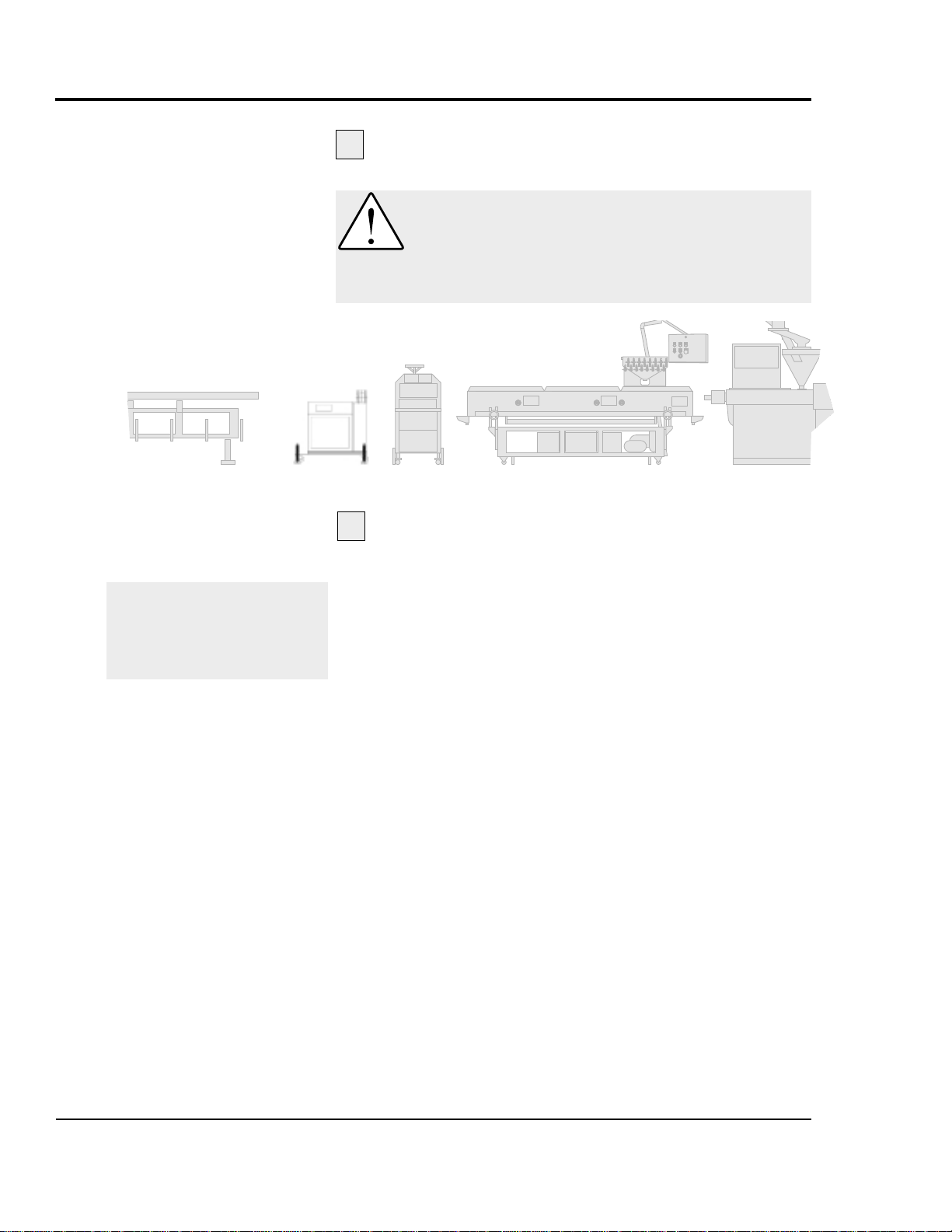
Move the servo cutter into position. Place the
servo cutter in position downstream of the belt puller.
Determine the best distance from the belt puller to
the SC-5 Sure Cut cutter.
● For flexible products, the cutter should be located
as close to the puller as possible to insure a minimum amount of space for the product between the
point of exit of the puller and the inlet to the cutter
bushing for most flexible products.
● For rigid products, allow some deflection space
between the puller and cutter. This will minimize
product sag or excessive deflection during cutting
which could affect the cut length accuracy.
As a general rule, place the cutter such that you feel
no shock from the cut with your fingernail placed
on the extrudate on the entrance of the puller. If you
feel shock form the cut, simply allow more space
between the cutter and puller.
SC-5 SURE CUT Servo Knife Cutter UGE059/1003
3-4 INSTALLATION
1
P
OSITIONING
THE
SERVO
CUTTER
CAUTION: Lifting
To avoid personal injury or damage to the cutter, lift the cutter using a for klift or hoist with
straps that have been positioned at the cutter's
center of gravity.
2
NOTE: If the slide base option
was purchased, the cutting
chamber can be slid back from
the frame to allow ease of the
string up procedure.
SC-5 Cutter
Continued
Page 25
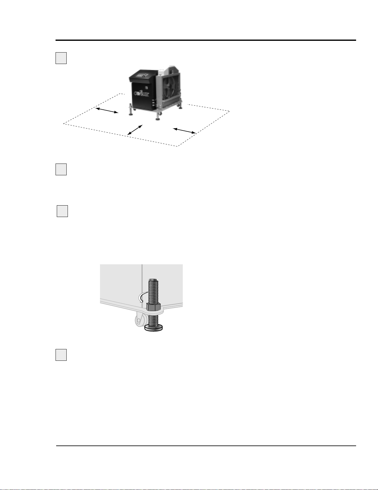
Align the cutter with the extrusion line.
Measure the centerline height of the extrudate as
it exits the extrusion die. Adjust all equipment on the extrusion
line (sizing tank, cooling tanks, belt puller, and cutter) to this
height.
Adjust the cutter's floorlock/caster assembly
to the center height of the extrusion line using a 16- or
18-inch adjustable wrench. Once the correct height is
reached, adjust the pad assembly to remove the weight
from the casters for operation. This minimizes machine
vibration during the cutting cycle.
Use a plumb line or laser to check for a
straight line
from the extrusion die through each line
component to the cutter bushings. Adjust as necessary.
UGE059/1003 SC-5 SURE CUT Servo Knife Cutter
INSTALLATION 3-5
4
5
6
3
POSITIONING
THE
SERVO
CUTTER
CONTINUED
Page 26
3-6 INSTALLATION
Open the servo cutter’s electrical
enclosure.
Turn the disconnect dial on
the door to the OFF or O position and
open the door.
Insert the main power wire through the knockout
in the side of the enclosure. Secure the wire with a rubber
compression fitting or strain relief.
Connect the power wires to the terminals indicated
on the wiring diagram that came with your machine.
1
2
IMPORTANT: Always refer to
the wiring diagrams that
came with your servo cutter
before making electrical connections.The diagrams show
the minimum size main power
cable required for your cutter,
and the most accurate electrical component information.
CONNECTING
THE
MAIN
POWER SOURCE
3
WARNING: Electrical hazard
Before performing any work on this product, disconnect and lock out electrical power sources
to prevent injury from unexpected energization
or start-up. A lockable device has been provided to isolate this product from potentially hazardous electricity.
WARNING: Improper installation, operation, or servicing may result in
equipment damage or personal injury.
This equipment should only be installed, adjusted, and serviced by qualified technical personnel who are familiar with the construction, operation, and potential hazards of this type of
machine.
All wiring, disconnects, and fuses should be
installed by qualified electrical technicians in
accordance with electrical codes in your region.
Always maintain a safe ground. Do not operate
the equipment at power levels other than what
is specified on the machine serial tag and data
plate.
SC-5 SURE CUT Servo Knife Cutter UGE059/1003
Check every terminal screw to make sure wires are
secure. Gently tug each wire. If a wire is loose, use a
screwdriver to tighten the terminal.
Connect the ground wire to either grounding point
shown in the diagram.
4
5
Page 27
UGE059/1003 SC-5 SURE CUT Servo Knife Cutter
INSTALLATION 3-7
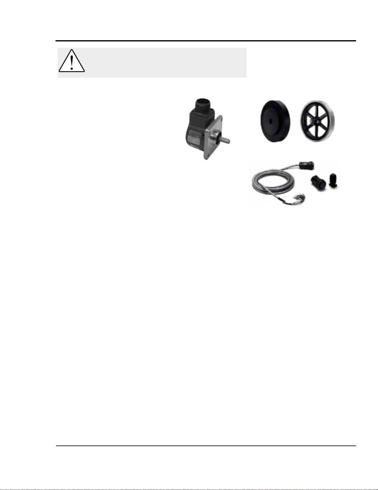
Conair uses bi-directional encoders to ensure that only product
that moves forward is counted.
Installing the encoder consists of several parts:
● the encoder
● the measuring wheel
● the connecting cable
The encoder is fitted with a one foot
circumference wheel which rides on
either the upper belt of the belt puller or (for rigid profiles and
pipe) on the extrudate itself upstream of the puller.
The encoder is supplied with an integral mounting bracket.
How and where you attach the encoder to the puller depends
on your particular puller and application.
● If the wheel rides on the puller belt, make sure that its lin-
ear alignment is the same as the belt. Place the wheel near
the center of the belt to minimize bouncing. Try to avoid
cracks and other belt features that may effect accuracy.
● Make sure the location allows you to keep the wheel
clean. Any small buildup on the wheel will effect its circumference and change the cut length.
After the encoder is installed, attach it to the cutter control
using the supplied cable. The cable has been hard-wired to the
control at the factory.
INSTALLING THE
ENCODER
CAUTION: Handle with care.
The encoder is a delicate piece of equipment
and must be handled gently.
Wheels
Connecting
Cable
Encoder
Page 28
SC-5 SURE CUT Servo Knife Cutter UGE059/1003
3-8 INSTALLATION
I
NSTALLING THE
CUTTER
BLADES
DANGER: Sharp blades!
Most injuries caused by knife blades occur
when the cutter has been turned off. Handle
blades with care at all times.
● Always lock out power to the cutter before
opening the cutting chamber.
● Always wear cut-resistant gloves when the
cutting chamber is open and when handling
blades.
● Always wait until the cutter head has completely stopped before opening the knife
guard.
SC-5 Sure Cut cutters are equipped with several safety devices to ensure safe operation.
Never remove or disable these devices to sustain production. Operating without these devices
can cause severe injury.
Never attempt to change or work on Blades
without first locking out power to the machine.
● When the knife guard is opened, the
knife guard switch stops the cutter.
● Two proximity-type safety switches prevent
operation unless the cutter bushings
are in place.
● The STOP button activates a circuit that
stops the cutter head.
Installing the Cutter Blades
Shut off the main power disconnect and
unplug the main power cord
when entering the
cutter housing. There is a safety interlock on the cutter
blade housing that will deactivate the servo amplifier and
control system.
Remove the screws holding the blades,
remove the old blades and insert the new
blades.
The blade, or blades as the case may be, will fit
onto a roll pin or in a machined slot with a blade
clamp to squeeze or tighten. Secure the blade.
For more information about choosing the appropriate blade for
your material, see the Appendix B.
1
2
Continued
Page 29
INSTALLATION 3-9
UGE059/1003 SC-5 SURE CUT Servo Knife Cutter
TIP: We recommend that you:
● Apply some protective cover on the portion of
the blade you are handling, such as masking tape
to help prevent getting cut during installation and to
leave it on until such time that you will start and
check the cutting operation.
● Check the length that the blade extends out of
the cutter blade wheel. The blade needs to be
carefully checked to insure that the entire blade will
pass completely through the product.
This is especially important with the very first insta-
llation and can be accomplished by rotating the
wheel with the blade installed manually though the
bushing and visually check to see that it will completely cover the entire bore of the bushing.
INSTALLING THE
CUTTER
BLADES
C
ONTINUED
CAUTION:Never attempt to change or work on
blades without first locking out power to the
machine.
CAUTION: Use extreme caution as the blades
will be very sharp.With the power off, the blade
wheel can spin freely.
Page 30

DANGER: Sharp blades!
Always wear cut-resistant gloves when the cutting chamber is open and when handling
blades.Never open cutting chamber without
locking out the cutter power and waiting until
the cutter head stops spinning.
3-10
INSTALLATION
SC-5 SURE CUT Servo Knife Cutter UGE059/1003
MOUNTING THE
CUTTER
BUSHINGS
The Bushings
Generally, the bushing will be in two parts, an inlet and an
outlet with the inlet bushing being tapered or otherwise contoured to assist in guiding the product into the cutter mechanism. It is extremely crucial to the success of the cutting
process that bushing bores be exact and in perfect alignment
with each half. They should be polished smoothed, burr free
and generally several thousands oversized for optimum performance.
Installation of the bushing
Open the top hinged cover (yellow) to expose
the top of the bushing holder.
Use the two set screws positioned on top of the
bushing holder and turn them counterclock
wise to loosen and remove the bushings.
Replace the desired bushings and tighten up
the two set screws just enough to barely be
able to move the bushings.
Rotate the blade wheel until the blade enters
the space between the two bushings.
Move the outlet bushing in until you can bare-
ly feel the blade scrape along the inside of the
bushing.
Move the inlet bushing inward until there is
about 0.001 to 0.003 inch clearance between
the blade and the outlet bushing.
Tighten the two screws in the housing to lock
in the bushings.
Rotate the blade wheel
by hand so that the blade
passes through the space between the two bushings to
insure that it will clear without hitting either bushing and
passes through the space with little effort.
1
2
3
4
5
6
7
8
Page 31

UGE059/1003 SC-5 SURE CUT Servo Knife Cutter
INSTALLATION 3-11
CHECKING THE
ALIGNMENT OF
THE
BUSHINGS
For more information about
setting and adjusting the gap
for the bushings, see About
Cutter Bushings in the
Appendix C.
Checking the Alignment of bushing to blade
Once you are sure that the blade will easily clear the bushings as it goes through the space you should then make
some test cuts to insure quality.
Close the safety cover.
Turn on the Power (Rotary main disconnect).
Press the Green start button.
Do several test cuts by pressing the manual
cut button.
Check the quality of the cuts. Adjust the bushing if necessary.
1
2
3
4
5
Page 32

SC-5 SURE CUT Servo Knife Cutter UGE059/1003
3-12 INSTALLATION
CHECKING
REPEATABILITY
Before any Conair SC-5’s are shipped, they are tested for cut
time repeatability to be sure they are within performance specifications. The repeatability test checks the performance of the
rotary knife cutter to return to the home park position after a
complete cut. Acceptable repeatability times allowed for each
cutter model prior to shipping are:
Type of Cutter Repeatability Time
AC Pneumatic Cutter Less than 1 millisecond
DC Pneumatic Cutter Less than 1.5 millisecond
Positional Servo Less than 0.1 millisecond
Note: 1-millisecond at 60 feet per minute is equal to 0.012 inches.
The repeatability mode is built into the Conair cutter controls
and allows you to perform similar tests, without any external
test equipment. It is recommended that you check repeatability
on a regular basis. Refer to Operation Section 4, Control
Instructions Test to run repeatability tests. Acceleration/deceleration delays of the servo do not contribute to repeatability
error; any error is attributed solely to motor stability, couplings, assembly, power, and proximity sensor alignment.
Use any blade speed and line speed. The line speed is only
seen while in the Encoder or Product modes. It is recommended that the tests be performed at cut intervals between 0.5 and
5-seconds. Do not change the blade speed or the line speed
after starting the test.
Page 33

UGE059/1003 SC-5 SURE CUT Servo Knife Cutter
INSTALLATION 3-13
Make sure all components are installed according
to assembly drawings. Make sure that all bolts on the cutter have been tightened.
Check that cutter is firmly locked into position
with the anchoring screws.
Check that all wiring conforms to electrical
codes
, and all wiring covers are in place.
Locate the main disconnect switch on the front
of the control cabinet.
Turn it on. You should see the
Redlion interface illuminate and start communications
and the yellow power light should now be on.
Make sure the bushings and the blade doors
are in place and secure.
Check that the bushing
access door is closed and the threaded knob is tight and
the E-stop is in the out position.
Press the green start button. If the guard circuit is
ready the green start button will now be illuminated.
Do a test cut, by pressing the black manual cut
button.
You should have caused the flywheel to com-
plete on test cut.
To enable the cutter, push the center arrow
key .
If for any reason any of these steps could not be achieved
please refer to the troubleshooting section of the manual.
1
2
PREPARING FOR
TESTING
1
3
TESTING THE
INSTALLATION
2
3
4
5
Page 34

Page 35

4-1
UGE059/1003 SC-5 SURE CUT Servo Knife Cutter
●●
The Cutter Control . . . . . . . . . . .4-2
●●
Before Starting . . . . . . . . . . . . . .4-3
●●
Powering Up . . . . . . . . . . . . . . . .4-3
●●
Main Screen . . . . . . . . . . . . . . . .4-5
●●
Total Screen . . . . . . . . . . . . . . . .4-6
●●
Batch Screen . . . . . . . . . . . . . . .4-7
●●
Length Screen . . . . . . . . . . . . . .4-9
●●
Preset to Run . . . . . . . . . . . . . .4-10
●●
Time Preset . . . . . . . . . . . . . . .4-11
●●
Blade Speed . . . . . . . . . . . . . . .4-13
●●
Function Areas . . . . . . . . . . . . .4-15
●●
Test Screen . . . . . . . . . . . . . . . .4-16
●●
Cut Mode . . . . . . . . . . . . . . . . .4-18
●●
Min. Measurement . . . . . . . . . .4-19
●●
Maintenance Area . . . . . . . . . .4-19
●●
Encoder Area . . . . . . . . . . . . . .4-20
●●
Unit of Measure . . . . . . . . . . . .4-22
●●
Scale Distance . . . . . . . . . . . . .4-23
●●
Homing . . . . . . . . . . . . . . . . . . .4-25
●●
Offset Example . . . . . . . . . . . . .4-26
●●
Preventative Maintenance . . . .4-27
●●
Power On Time . . . . . . . . . . . . .4-28
●●
Checking Cut Quality . . . . . . . .4-29
●●
Starting the SC-5 Sure Cut . . .4-29
●●
Making Adjustments
During the Operation . . . .4-30
●●
Stopping the SC-5 Sure Cut . .4-31
OPERATION
Page 36

SC-5 SURE CUT Servo Knife Cutter UGE059/1003
4-2 OPERATION
OPERATOR
CONTROL
FEATURES
The Operator Control provides an intuitive user-friendly
method to interface with the Conair Servo Cutter. Information
is viewed and entered at the Operator Control and is communicated to the servo positional amplifier via the RS-232 serial
communication link.
The Operator Control is a flat membrane panel consisting of
22-keys and a large 2 line x 20 back lit LCD screen.
Soft Keys-allows
the operator to
select different
functions.
Numeric KeysPermits data entry
for the operator
Fixed Function
Keys-Contain uni-
versal symbols &
text
Soft Keys
Soft keys - these are the three keys directly under the display.
All three have a triangle on them. Occasionally, pages will
appear that allow the operator to use one of the soft keys. On
those occasions, text would typically appear directly above
the key and the key will have a function. Think of the text as
the soft key function indicator or title. These keys will be
referred to in this manual from left to right as soft keys 1, 2
and 3 respectively.
Numeric keys
These are the black keys containing numbers 0 to 9. Numbers
permit data entry of parameters. See Raise and Lower for
value trim.
Fixed Function Keys (at Bottom)
Underneath the numeric keys are fixed function keys. They
contain universal symbols and text. The fixed function keys
are Raise, Lower, Next, Prev (previous), Enter, Delete, Exit,
Menu and Mute. These functions are described in the
"Function keys - Fixed Functions" section of this manual.
LCD Screen
The screen shows various pages depending on operator
actions. In addition, it is used to indicate warnings.
Mostly, it is used for viewing status and for setting parameters.
CONAIR SERVO CUTTER
Version 1.0
Page 37
UGE059/1003 SC-5 SURE CUT Servo Knife Cutter
OPERATION 4-3
Before you start daily operation of the servo cutter, you need
to perform preventative maintenance. Necessary maintenance
is described in the Maintenance section of this Users Guide,
see preventative maintenance, Section 5.
Daily maintenance includes:
● Inspecting the cutter blades
● Inspecting the blade mounting hardware
● Making sure the cutter bushings are properly secured
● Inspecting the closure latch on the knife guard
● Checking cutter alignment with extrusion line
● Performing any floor lock adjustments as needed
These items and weekly, monthly, and semi-annual maintenance procedures are detailed in the Maintenance section of
this User Guide.
Plug in the power cord to restore power after any
required maintenance.
Turn on the main power. The cutter control will
bootup. The amber power on light illuminates.
While the cutter is booting up, perform the next three steps:
Make sure the E-Stop button is in the out,
extended position.
Make sure that the Cut Enable is Off.
If necessary, press button to display off.
Press Start Cutter button.The light in the button
should light. On SC-5 cutters, the cutter head will make
one revolution until it finds its home offset position.
BEFORE
STARTING
WARNING: Be sure that power to the SC-5
cutter is OFF when doing any maintenance on
the servo cutter.Follow all safety rules when
performing any maintenance on this equipment.
P
OWERING U
P
NOTE:You can watch the servo motor amplifier's
status screen during bootup through the
window on the back of the electrical enclosure.This display gives information that may
be useful if you have a problem. See the
Troubleshooting section.
1
2
3
4
5
Continued
Page 38

SC-5 SURE CUT Servo Knife Cutter UGE059/1003
4-4 OPERATION
POWERING UP
C
ONTINUED
Open the knife guard. The machine start push
button should go out.
If the cutter is not working properly at any time, turn it off
immediately and refer to the Troubleshooting section of this
User Guide.
If you do not encounter any problems, proceed to the
Operation section.
Power Up Sequence
At power up a series of system screens briefly appear. The
software is Red Lion's Edict-97. This screen or similar shows
first.
Next, the Communications message appears
If there are any problems with communications, this screen
will remain on longer than a couple of seconds.
If there are no communication problems the Conair SC-5
Cutter program will begin to run. The following message or
similar shows for 5-seconds.
After the 5 second delay the Main Screen will appear.
Note: If “Home Runtime Failed” message is dis
played.Check for malfunctions of misadjusted
sensor.
6
Edict-97 Runtime
Ver. 5.05.134
**STARTING COMMS**
CONAIR SERVO CUTTER
Version 1.0
Page 39

UGE059/1003 SC-5 SURE CUT Servo Knife Cutter
OPERATION 4-5
MAIN SCREEN
There are two types of main screens, length or time measurement and cuts per minute measurement. The type displayed
varies depending on the current cut mode setting.
See the mode operator display overviews.
The Main Screen has seven features. The top line displays the
active preset (only with multi preset option), cut mode, active
measurement and the unit of measure. The bottom line contains three soft key functions, softkey1/Parts, softkey2/cut
On/Off and softkey3, which varies depending on the current
cut mode setting.
Active Preset
With the multi preset option in on-demand modes the active
preset value changes upon batch completion. As the cutter
sequences through multiple presets, the operator always
knows which preset is being processed.
Active Measurement
The measurement value displayed will be the active length or
time preset or cuts per minute depending on the active cut
mode. It displays the value only when the machine is started
and softkey2 On/Off is on. If the machine is stopped or softkey2 On/Off is off, this counter will be forced to zero.
If a negative symbol is shown to the left of the measurement
value, the encoder signal is reversed, i.e. rotating in the wrong
direction. The Cutter will not function while the encoder is
going negative. It is possible to correct this by using the
encoder direction function located in the encoder area of the
maintenance area. See the maintenance area display overview.
Length, Time or Blade Softkey
This key is mode dependent see the mode operator display
overview for the current cut mode.
On/Off Softkey
Under the active measurement in the center of the bottom line
of the display is a soft key labeled On or Off. Pressing this
key while On is displayed will disable the cutter. Likewise
pressing this key while Off is displayed enables the cutter.
Pressing the stop button forces the cut enable off.
Manual cuts can still be made while the cut enable is off.
OPERATOR
CONTROL
INSTRUCTIONS
MAIN SCREEN
1 ENC 00000.000 in.
Parts Off Length
Page 40
4-6 OPERATION
Menu function key is used to access the Menu Area.
This area can only be accessed from the main display
screen for each mode. See the Menu Area section for more
information.
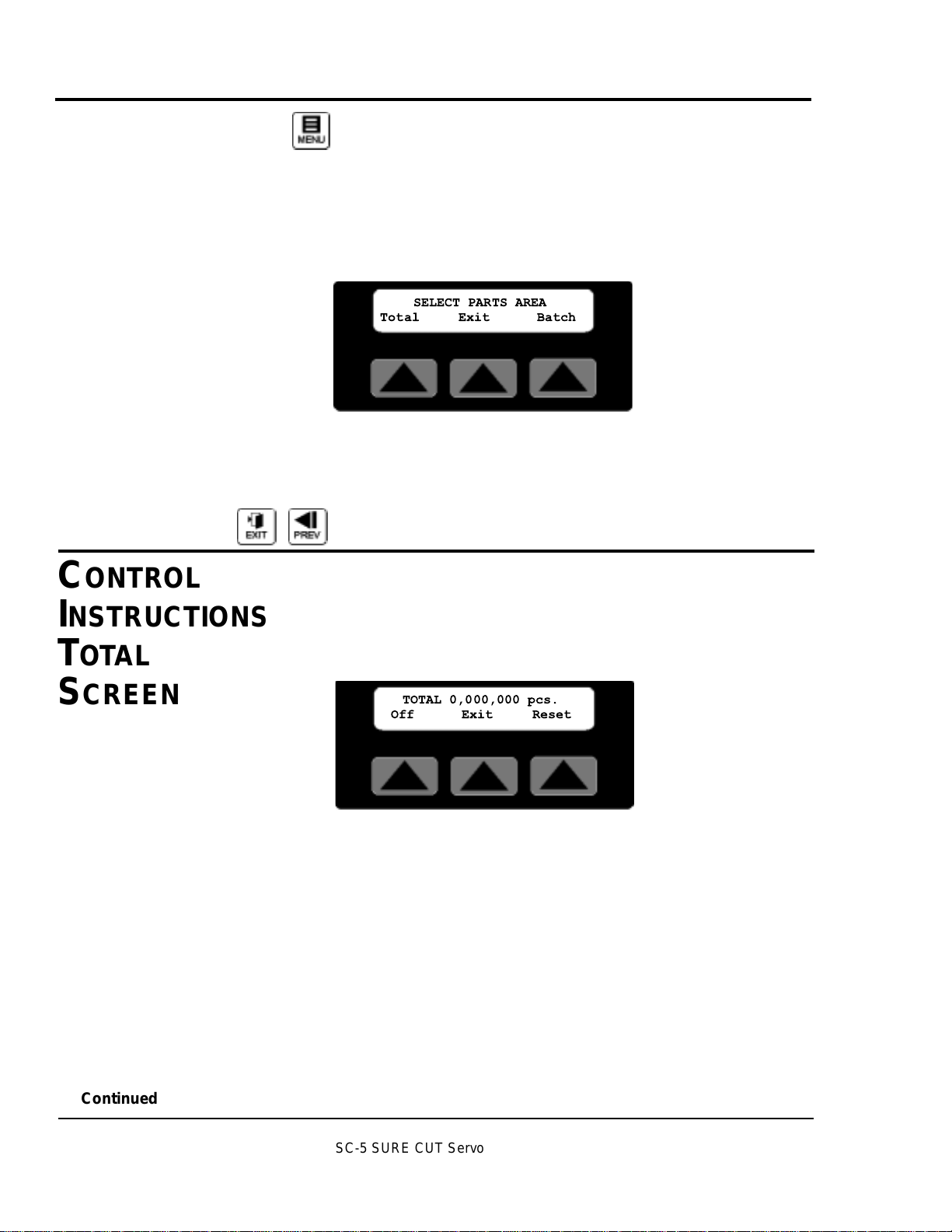
Parts Select Area Screen
Under the current mode on the left side of the bottom line of
the display is a soft key labeled Parts. Pressing this key
accesses the Parts Select Screen.
This screen provides access to the parts Total/softkey1 or
Batch/softkey3 areas. Pressing Exit/softkey2 returns the display to the active main screen. If no selection is made within
30 seconds the display returns to the active main screen.
EXIT or PREV, fixed function keys return the display to the
previous screen.
TOTAL SCREEN
By pressing softkey1 located under the word Total on the Parts
Select Screen, a seven-decade total counter is available.
Additional information on how to access this screen can be
found in the operator display overview in Appendix E of this
manual.
This is typically used to count cut pieces during the day or
days that the product is being produced. Sample or manual
cuts are not counted. When enabled the count continues to
accumulate even if the total display is not being viewed. It is
also possible to turn this counter off or on.
On/Off Softkey1
Under the counter on the left is a soft key labeled On or Off.
Pressing this key while On is displayed will disable the
counter. Likewise pressing this key while Off is displayed
enables the counter.
Exit Softkey2
Under the counter, in the center is a soft key labeled Exit.
Pressing this key will return the display to the Parts Select
screen.
CONTROL
INSTRUCTIONS
C
ONTROL
INSTRUCTIONS
TOT AL
S
CREEN
Continued
SC-5 SURE CUT Servo Knife Cutter UGE059/1003
SELECT PARTS AREA
Total Exit Batch
TOTAL 0,000,000 pcs.
Off Exit Reset
Page 41
OPERATION 4-7
Reset Softkey3
Under the counter, on the right is a soft key labeled Reset.
Pressing this key will zero the counter.
EXIT or PREV, fixed function keys return the display to the
Parts Select screen.
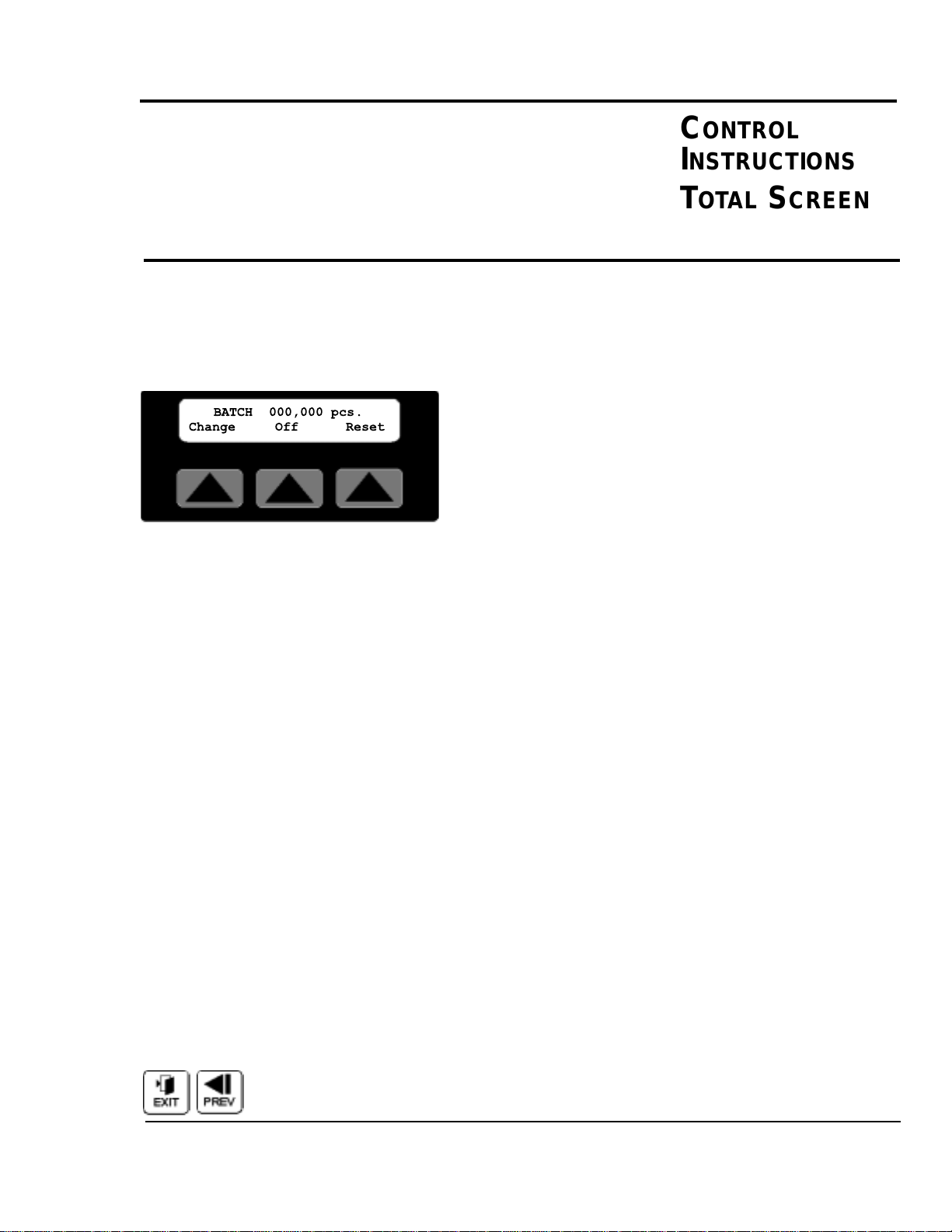
BATCH SCREEN
By pressing softkey3 located under the word Batch on the
Parts Select Screen, a six-decade Batch counter is available.
Additional information on how to access this screen can be
found in the operator display overview in Appendix E of this
manual.
This is typically used to count the pieces required to fill a carton, with the product being cut. The batch counter counts up
to the batch preset and resets to zero. As the accumulated
count reaches the alarm preset the batch pre-warn output-3
energizes then when the batch preset is reached the batch
complete output-2 briefly energizes and both outputs turn
back off. Sample/Manual cuts are not counted. When enabled
the count continues to accumulate even if the batch display is
not being viewed. It is also possible to turn this counter off or
on.
Change Softkey1
Under the counter, on the left is a soft key labeled Change.
Pressing this key displays the Select Batch Area screen. The
operator can then choose to set the batch or alarm preset.
On/Off Softkey2
Under the counter near the center is a soft key labeled On or
Off. Pressing this key while On is displayed will disable the
counter. Likewise pressing this key while Off is displayed
enables the counter.
Reset Softkey3
Under the counter, on the right is a soft key labeled Reset.
Pressing this key will zero the batch counter.
EXIT or PREV, fixed function keys return the display to the
Parts Select screen.
CONTROL
INSTRUCTIONS
BATCH
SCREEN
CONTROL
INSTRUCTIONS
TOTAL SCREEN
CONTINUED
Continued
UGE059/1003 SC-5 SURE CUT Servo Knife Cutter
BATCH 000,000 pcs.
Change Off Reset
Page 42

SC-5 SURE CUT Servo Knife Cutter UGE059/1003
4-8 OPERATION
Batch Select Area Screen
Under the batch counter, on the left is a soft key labeled
Change. Pressing this key displays the Select Batch Area
screen. Additional information on how to access this screen
can be found in the operator display overview in Appendix E
of this manual.
This screen provides access to the batch Preset/softkey1 or
batch Alarm/softkey3 areas. Pressing Exit/softkey2 returns the
display to the batch counter screen. If no selection is made
within 30 seconds the display returns to batch counter screen.
Batch Preset Screen
By pressing the soft key located under the word Batch on the
Batch Area Screen, the preset for the Batch counter is available.
The number shown is the current batch preset. A cursor will
appear in the least significant digit. The user has a choice of
ways to adjust this number.
Exit or Prev, If no change is required press Exit or Prev to
return to the Main screen.
Raise will increase the preset by 1. The key can be pressed
once for each increment required or held down to scroll up.
Releasing the key will freeze the preset at the last value.
Lower will decrease the preset by 1. The key can be pressed
once for each decrement required or held down to scroll
down. Releasing the key will freeze the preset at the last
value.
CONTROL
INSTRUCTIONS
BATCH
SCREEN
C
ONTINUED
Continued
SELECT BATCH AREA
Preset Exit Alarm
PRESET 000,000
Exit
pcs
Page 43
UGE059/1003 SC-5 SURE CUT Servo Knife Cutter
OPERATION 4-9
Numeric keys
Key in the batch required and press enter. If you require a
batch of 50 parts you must key in 50 and then press enter.
Enter or Delete?
If the keyed in number is correct press the enter key for it to
be accepted and return to the Main screen. If it is wrong press
the delete key and the previous preset will reappear.
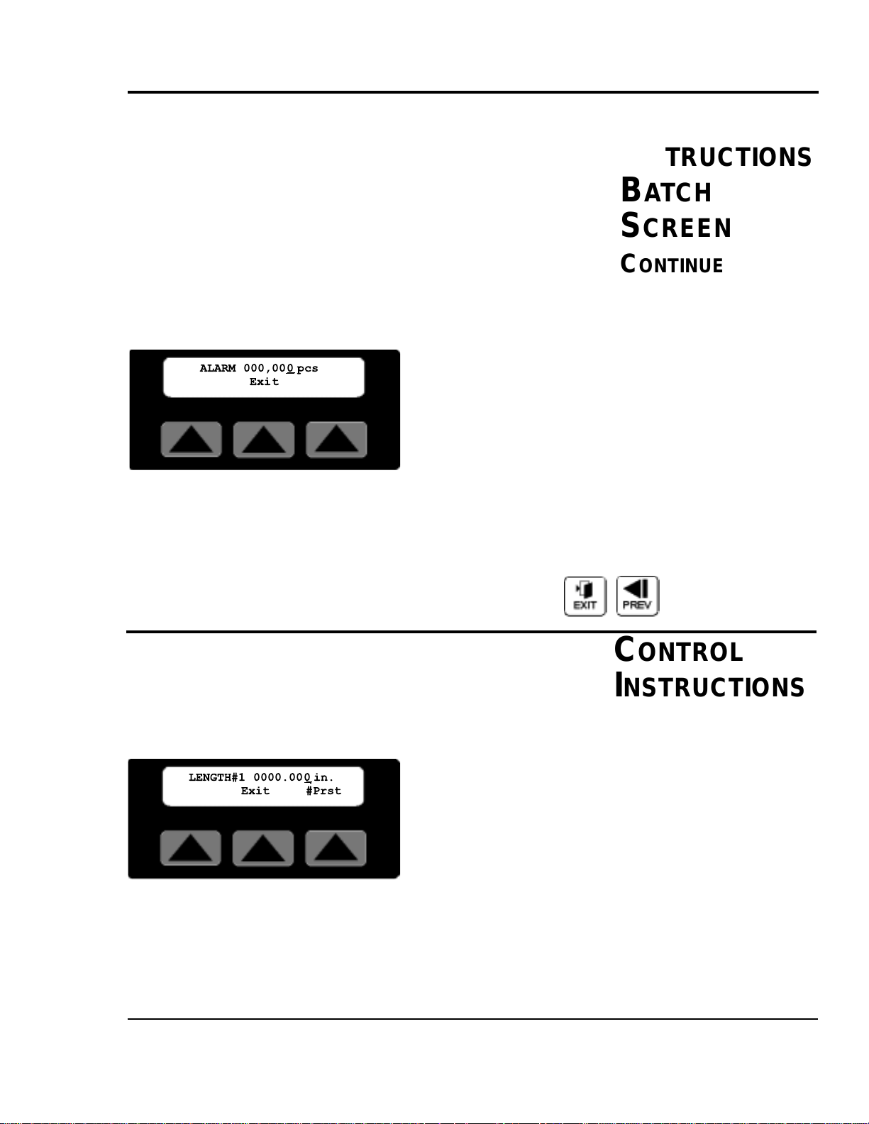
Batch Pre-Alarm Preset Screen
By pressing the soft key located under the word Alarm on the
Batch Area Screen, the preset for the Batch pre-warn Alarm is
available.
The number shown is the current alarm preset. A cursor will
appear in the least significant digit. The user has a choice of
ways to adjust this number. See entering the batch preset
above. Please note: This value must be less than the batch
preset.
Exit or Prev, if no change is required press Exit or Prev to
return to the Main screen.
LENGTH SCREEN
By pressing the soft key located under the word Length on
the Encoder, Follower or Auto Mode Main Screen, the preset
for the Length counter is available. Additional information on
how to access this screen can be found in the operator display overview in Appendix E of this manual.
The number shown is the current length preset value, i.e. the
length to cut the product. A cursor will appear in the least
significant digit. The user has a choice of ways to adjust this
number. Pressing the #Prst/Softkey3 accesses the number of
presets to run screen. This feature is only available with the
multiple preset/batch option.
CONTROL
INSTRUCTIONS
LENGTH
SCREEN
Continued
CONTROL
INSTRUCTIONS
BATCH
SCREEN
C
ONTINUED
ALARM 000,00
Exit
pcs
0
LENGTH#1 0000.00
Exit #Prst
0 in.
Page 44

SC-5 SURE CUT Servo Knife Cutter UGE059/1003
4-10 OPERATION
Exit or Prev, if no change is required press Exit or
Prev to return to the Main screen.
Raise will increase the preset by 0.010 inch. The key can be
pressed once for each 0.010 inches increment required or held
down to scroll up. Releasing the key will freeze the preset at
the last value then press enter.
Lower will decrease the preset by 0.010 inch. The key can be
pressed once for each 0.010 inch decrement required or held
down to scroll down. Releasing the key will freeze the preset
at the last value then press enter.
Numeric keys
Key in the length required and press enter. The decimal place
is fixed so remember this when entering the preset. If you
require 24 inches you must key in 24000 and then press enter.
Keying only 24 will set the length to 0.024 inches.
Enter or Delete?
If the keyed in number is correct press the enter key for it to
be accepted and return to the Main screen. If it is wrong press
the delete key and the previous preset will reappear.
PRESETS TO RUN SCREEN
By pressing the soft key located under the word #Prst on any
Length Screen, the value for the number of presets to run is
available. Additional information on how to access this screen
can be found on the multiple preset example in the operator
display overview in Appendix E of this manual.
The number shown is the current number of presets to run
value, i.e. how many measurement presets and batches to run.
The acceptable range for this value is 1 to 4. The cutter will
process preset#1/batch#1 then #2 then #3 then #4 and back to
#1 continuously. If a 2 is entered only preset/batch 1 and 2 are
processed. A cursor will appear in the least significant digit.
The user has a choice of ways to adjust this number.
CONTROL
I
NSTRUCTIONS
PRESET TO
RUN SCREEN
Continued
CONTROL
INSTRUCTIONS
LENGTH
SCREEN
C
ONTINUED
RUN 4 PRESETS
Exit
Page 45

UGE059/1003 SC-5 SURE CUT Servo Knife Cutter
OPERATION 4-11
Exit or Prev, If no change is required press Exit or Prev to
return to the previous Length Screen.
Raise will increase the number by 1. The key can be pressed
once for each increment of 1 required or held down to scroll
up. Releasing the key will freeze the preset at the last value
then press enter.
Lower will decrease the preset by 1. The key can be pressed
once for each decrement of 1 required or held down to scroll
down. Releasing the key will freeze the preset at the last
value then press enter.
Numeric keys
Key in the number required and press enter. If you require 4
presets key in 4 and then press enter.
Enter or Delete?
If the keyed in number is correct press the enter key for it to
be accepted and return to the Main Timer Mode screen. If it
is wrong press the delete key and the previous preset will
reappear.
TIME SCREEN
By pressing the soft key located under the word Time on the
Main Timer Mode Screen, the preset for the timer is available. Additional information on how to access this screen can
be found in the operator display overview in Appendix E of
this manual.
The number shown is the current time preset value, i.e. the
time interval to cut the product. A cursor will appear in the
least significant digit. The user has a choice of ways to adjust
this number.
Exit or Prev, If no change is required press Exit or Prev to
return to the Main Timer Mode Screen.
C
ONTROL
INSTRUCTIONS
TIME SCREEN
CONTROL
INSTRUCTIONS
PRESET TO
RUN SCREEN
CONTINUED
Continued
TIME 00000.00 0
Exit
sec
Page 46

SC-5 SURE CUT Servo Knife Cutter UGE059/1003
4-12 OPERATION
Raise will increase the preset by 0.010 second. The key can
be pressed once for each 0.010 second increment required or
held down to scroll up. Releasing the key will freeze the preset at the last value then press enter.
Lower will decrease the preset by 0.010 second. The key can
be pressed once for each 0.010 second decrement required or
held down to scroll down. Releasing the key will freeze the
preset at the last value then press enter.
Numeric keys
Key in the time required and press enter. The decimal place is
fixed so remember this when entering the preset. If you
require 1.5 seconds you must key in 1500 and then press enter.
Keying only 15 will set the time to 0.015 seconds.
Enter or Delete?
If the keyed in number is correct press the enter key for it to
be accepted and return to the Main Timer Mode screen. If it is
wrong press the delete key and the previous preset will reappear.
HOLD-OFF TIME SCREEN
By pressing the soft key located under the word Time on the
Main End Sense Mode Screen, the preset for the hold-off
timer is available. Additional information on how to access
this screen can be found in the operator display overview in
Appendix E of this manual.
The number shown is the current hold-off time preset, i.e. the
time interval to ignore the photo eye and avoid false cuts. A
cursor will appear in the least significant digit. The user has a
choice of ways to adjust this number.
Exit or Prev, If no change is required press Exit or Prev to
return to the Main End Sense Mode Screen.
C
ONTROL
INSTRUCTIONS
HOLD-OFF
S
CREEN
CONTROL
INSTRUCTIONS
TIME SCREEN
C
ONTINUED
Continued
Holdoff 00000.500
Exit
sec
Page 47

UGE059/1003 SC-5 SURE CUT Servo Knife Cutter
OPERATION 4-13
Raise will increase the preset by 0.010 second. The key can
be pressed once for each 0.010 second increment required or
held down to scroll up. Releasing the key will freeze the preset at the last value then press enter.
Lower will decrease the preset by 0.010 second. The key can
be pressed once for each 0.010 seconds decrement required or
held down to scroll down. Releasing the key will freeze the
preset at the last value then press enter.
Numeric keys
Key in the time required and press enter. The decimal place is
fixed so remember this when entering the preset. If you
require 1.000 seconds you must key in 1000 and then press
enter. Keying only 1 will set the time to 0.001 seconds and an
error message will be displayed.
Enter or Delete?
If the keyed in number is correct press the enter key for it to
be accepted and return to the Main End Sense Mode screen. If
it is wrong press the delete key and the previous preset will
reappear.
BLADE SPEED SCREEN
By pressing the soft key located under the word Blade or
Speed depending on the current mode, the preset for that
modes blade speed is available. Additional information on
how to access this screen can be found in the operator display
overview in Appendix E of this manual.
The number shown is the active modes current blade speed
preset, i.e. the speed the blade will pass through the part. A
cursor will appear in the least significant digit. The user has a
choice of ways to adjust this number.
Exit or Prev, if no change is required press Exit or Prev to
return to the Blade Select or Main Mode Screen.
C
ONTROL
I
NSTRUCTIONS
BLADE SPEED
S
CREEN
CONTROL
INSTRUCTIONS
HOLD-OFF
SCREEN
CONTINUED
Continued
SPEED 0750.0 rpm
Exit
Page 48
Raise will increase the preset by 1.0. The key can be pressed
once for each 1.0 increment required or held down to scroll
up. Releasing the key will freeze the preset at the last value
then press enter.
Lower will decrease the preset by 1.0. The key can be pressed
once for each 1.0 decrement required or held down to scroll
down. Releasing the key will freeze the preset at the last value
then press enter.
Numeric keys
Key in the time required and press enter. The decimal place is
fixed so remember this when entering the preset. If you
require 750.0 rpm you must key in 7500 and then press enter.
Keying only 750 will set the speed to 075.0 rpm and an error
message with the valid range will be displayed.
Enter or Delete?
If the keyed in number is correct press the enter key for it to
be accepted and return to the Blade Select or Main Mode
Screen. If it is wrong press the delete key and the previous
preset will reappear.
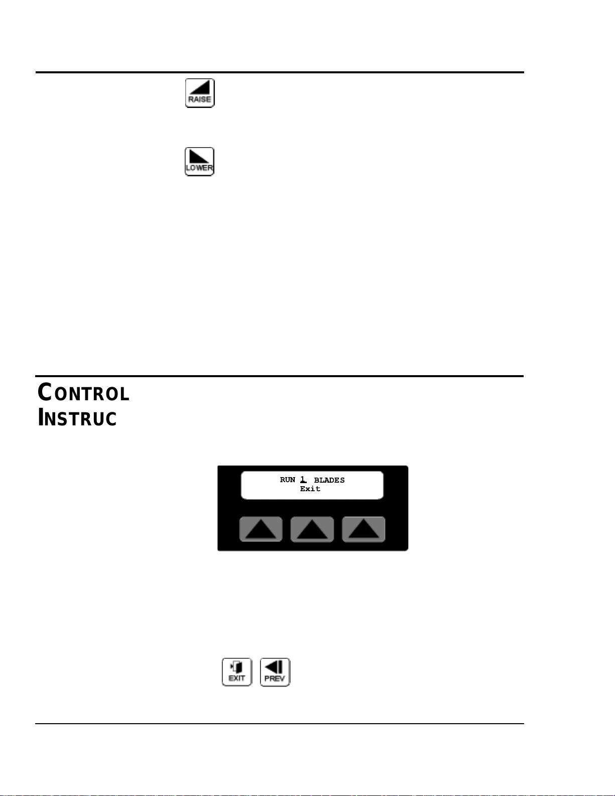
BLADE COUNT SCREEN
By pressing the soft key located under the word Blade or
Count depending on the current mode, the preset for the blade
count is available. Additional information on how to access
this screen can be found in the operator display overview in
Appendix E of this manual.
The number shown is the current blade count preset, i.e. the
number of blades mounted to the cutter head. A cursor will
appear in the least significant digit. The user has a choice of
ways to adjust this number.
Exit or Prev, if no change is required press Exit or Prev to
return to the Blade Select or Main Mode Screen.
CONTROL
INSTRUCTIONS
BLADE COUNT
SCREEN
Continued
CONTROL
INSTRUCTIONS
BLADE SPEED
SCREEN
CONTINUED
4-14 OPERATION
SC-5 SURE CUT Servo Knife Cutter UGE059/1003
1
RUN
BLADES
Exit
Page 49
Raise will increase the preset by 1. The key can be pressed
once for each 1 increment required or held down to scroll up.
Releasing the key will freeze the preset at the last value then
press enter.
Lower will decrease the preset by 1. The key can be pressed
once for each 1 decrement required or held down to scroll
down. Releasing the key will freeze the preset at the last value
then press enter.
Numeric keys
Key in the number of blades mounted and press enter. If the
value entered is out of range an error message with the valid
range will be displayed.
Enter or Delete?
If the keyed in number is correct press the enter key for it to
be accepted and return to the Blade Select or Main Mode
Screen. If it is wrong press the delete key and the previous
preset will reappear.
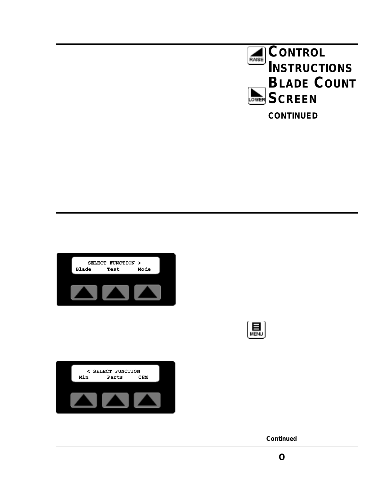
FUNCTION AREAS
Additional information on how to access and navigate these
screens can be found in the operator display overview section
of this manual.
Menu fixed function key is used to access the Function Areas
from any main mode screen. There are two Function Area
screens. The user can toggle between the two screens with the
Next and Prev fixed function keys.
CONTROL
I
NSTRUCTIONS
FUNCTION
AREAS
C
ONTROL
INSTRUCTIONS
BLADE COUNT
SCREEN
CONTINUED
Continued
O
PERATION 4-15
UGE059/1003 SC-5 SURE CUT Servo Knife Cutter
SELECT FUNCTION >
Blade Test Mode
< SELECT FUNCTION
Min Parts CPM
Page 50
Next or Prev, Pressing Next selects the second Function Area.
Pressing Prev returns the display to the first Function Area
screen. Pressing Prev from the first Function Area screen
returns the display to the active main mode screen.
Menus are a convenient way to access and monitor parameters
that do not need to be altered often, i.e. blade speed, blade
count, cut mode, repeatability test, min. allowable measurement and cuts per minute.
The most frequently used functions for a certain cutting mode
are directly available from the main screen for the active
mode. For a guide to screen navigation for any active mode
see the operator display overview section of this manual for
that mode. For information on the Blade and Parts Softkeys
see their respective sections covered earlier in this manual.
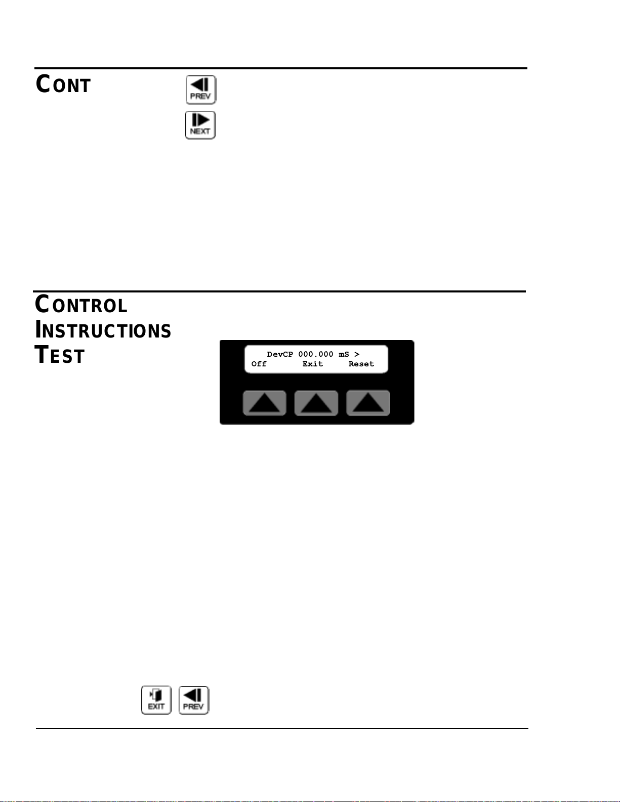
TEST SOFTKEY
Pressing soft key two located under the word Test on the first
Function area screen, selects the repeatability tester.
The DevCP repeatability tester displays total deviation time in
milliseconds. This time is from a cut being requested until the
blade reaches the part. The smallest measured value is subtracted from the largest measured value and the resulting deviation is displayed on the screen. New data is sampled every
consecutive cut. The DevCP repeatability test is available in
all on-demand modes. This test is used as a tool for verifying
the accuracy of the cutter.
On/Off Softkey1
On the display, on the lower left side is a soft key labeled On
or Off. Pressing this key while On is displayed will reset all
values and disable testing. Likewise pressing this key while
Off is displayed starts the test.
Reset Softkey3
On the display, on the lower right side is a soft key labeled
Reset. Pressing this key will reset all test values and start a
new test.
Exit or Prev, Pressing Exit, Prev or the Softkey under the
word Exit resets all values and disables testing then returns the
display to the Function area screen.
CONTROL
INSTRUCTIONS
T
EST
CONTROL
INSTRUCTIONS
FUNCTION
AREAS
C
ONTINUED
Continued
4-16 OPERATION
SC-5 SURE CUT Servo Knife Cutter UGE059/1003
DevCP 000.000 mS >
Off Exit Reset
Page 51

OPERATION 4-17
UGE059/1003 SC-5 SURE CUT Servo Knife Cutter
Next, Pressing Next selects the DevCC test if available. If the
arrow on the top right hand side of the screen is visible the
current mode also supports the DevCC test.
The DevCC repeatability tester also displays total deviation
time in milliseconds. This time is from a cut being
requested until the next cut request. The smallest measured
value is subtracted from the largest measured value and the
resulting deviation is displayed on the screen. The DevCC
repeatability test is available in some on-demand modes, and
all continuous modes. This test is used as a tool for verifying
the accuracy of the upstream puller or the precision timer
option.
On/Off Softkey1
On the display, on the lower left side is a soft key labeled On
or Off. Pressing this key while On is displayed will reset all
values and disable testing. Likewise pressing this key while
Off is displayed starts the test.
Reset Softkey3
On the display, on the lower right side is a soft key labeled
Reset. Pressing this key will reset all test values and start a
new test.
Exit, Pressing Exit or the Softkey under the word Exit resets
all values, disables testing then returns the display to the
Function area screen.
Prev, Pressing Prev selects the DevCP test if available. If the
arrow on the top left hand side of the screen is visible the current mode also supports the DevCP test.
NOTE:The test available DevCP, DevCC or both is
dependent on the active cut mode.
NOTE:The test available DevCP, DevCC or both is
dependent on the active cut mode.
C
ONTROL
I
NSTRUCTIONS
TEST
CONTINUED
< DevCC 000.000 mS
Off Exit Reset
Page 52
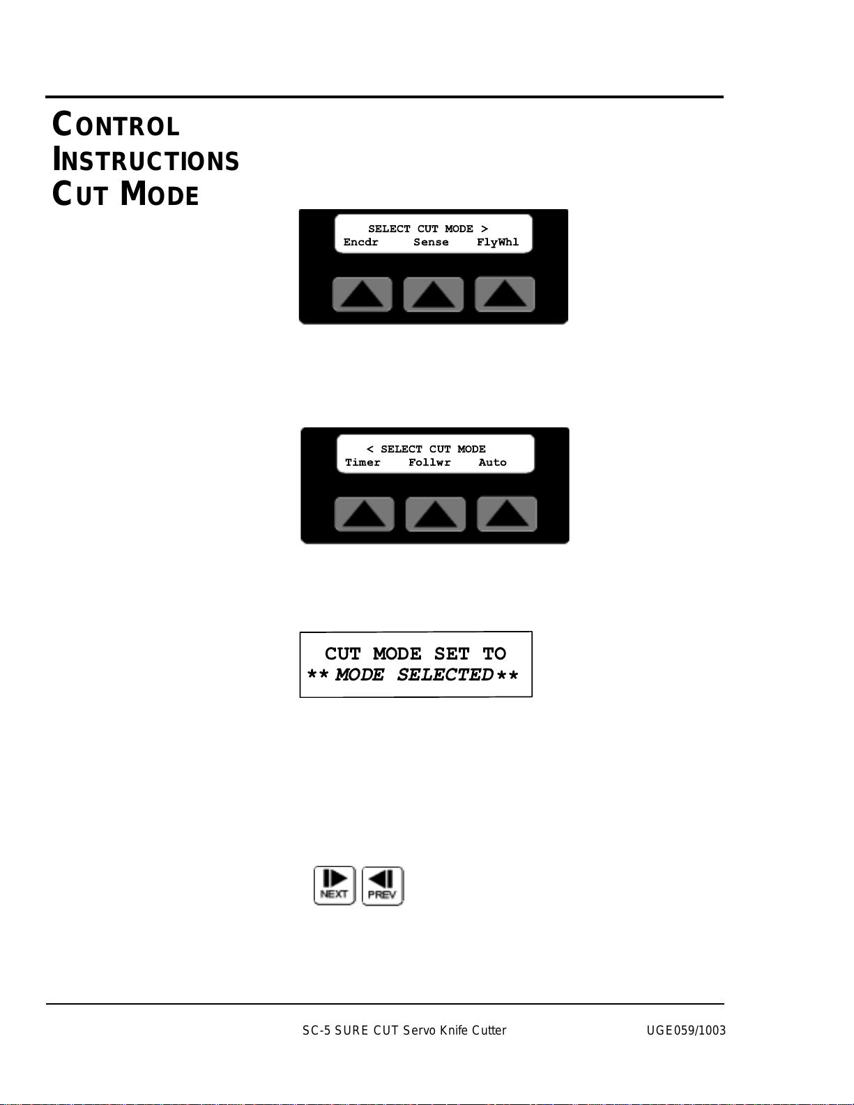
4-18 OPERATION
Mode Softkey
By pressing the soft key located under the word Mode, the different Cut Modes are available. There are two Cut Mode
screens. The first screen provides choices for the standardmodes available on all cutters.
The second screen displays choices for optional cut modes.
The user can toggle between the two screens with the Next
and Prev fixed function keys. Additional information on how
to access these screens can be found in the function area of the
operator display overview section of this manual.
Press the Softkey located under the cut mode desired to select
that mode. If the mode is available an acknowledgment will be
displayed.
This message will be displayed for 3 seconds or until any key
is pressed.
Next or Prev, Pressing Next selects the second Cut Mode
Area. Pressing Prev returns the display to the first Cut Mode
Area. Pressing Prev from the first Cut Mode Area screen
returns the display to the Function Area screen.
CONTROL
INSTRUCTIONS
CUT MODE
SC-5 SURE CUT Servo Knife Cutter UGE059/1003
SELECT CUT MODE >
Encdr Sense FlyWhl
< SELECT CUT MODE
Timer Follwr Auto
CUT MODE SET TO
MODE SELECTED
**
**
Page 53

OPERATION 4-19
UGE059/1003 SC-5 SURE CUT Servo Knife Cutter
Min Softkey
By pressing the soft key located under the word Min on the
second Function Area Screen, the Minimum allowable measurement value is displayed. The active mode and the
cuts per minute limit for the model of cutter determines the
actual value displayed. The screen will be displayed for 15
seconds or until any key is pressed, then return to the second
Function Area screen.
CPM Softkey
By pressing the soft key located under the word CPM on the
second Function Area Screen, the calculated cuts per minute
are displayed.
The active mode, measurement value, blade speed, number of
blades and line speed may all contribute to determining the
actual value displayed. The screen will be displayed for 15
seconds or until any key is pressed, then return to the second
Function Area screen.
MAINT. AREA
Menu function key is used from the first Function Area screen
to access the Maintenance area. There are two menus Maint.
and Factory, with access via password to various sub-menus.
C
ONTROL
INSTRUCTIONS
MINIMUM
MEASUREMENT
CONTROL
INSTRUCTIONS
MAINTENANCE
A
REA
CURRENT MIN TIME
IS 00000.150 sec.
THE CURRENT SETTINGS
PRODUCE 0000.000 cpm
SELECT MENU AREA
Maint. Factory
Page 54
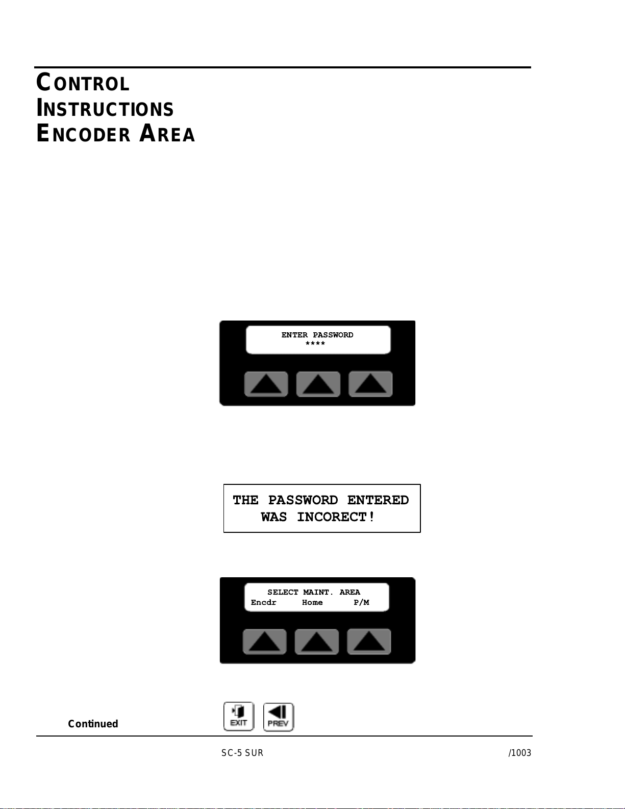
4-20 OPERATION
Menus are a convenient way to access and monitor parameters
that do not need to be altered often, i.e. home position,
encoder direction, scale or unit of measure. In addition, preventive maintenance parameters can be monitored for troubleshooting and scheduling purposes.
Factory Softkey
This area is password protected for factory use only.
Please do not attempt to get around the password protection as
parameters beyond this point are used for calibration and
setup. These parameters should only be modified by trained
personal. Improper settings will reduce the performance and
possibly cause severe damage to your machine.
Maint. Softkey
Located under the word Maint. is the Maintenance soft key.
The Maintenance area is password protected. This area should
only be accessed by qualified personal.
After pressing the Maintenance Softkey, the password entry
screen is displayed. With the numeral keys press 6 2 0 9 then
the Enter key to access the maintenance area. An improper
password will cause this message to be displayed for 3 seconds.
There are three sub-menus, Encdr, Home, and P/M accessible
in the maintenance area.
Exit or Prev, Pressing Exit or Prev will return the display to
the Menu Area screen.
CONTROL
INSTRUCTIONS
ENCODER AREA
Continued
SC-5 SURE CUT Servo Knife Cutter UGE059/1003
ENTER PASSWORD
****
THE PASSWORD ENTERED
WAS INCORECT!
SELECT MAINT. AREA
Encdr Home P/M
Page 55
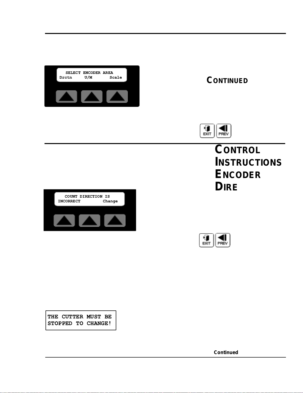
OPERATION 4-21
UGE059/1003 SC-5 SURE CUT Servo Knife Cutter
Encdr Softkey
By pressing the soft key located under the word Encdr on the
Maint. Area Screen, there are three sub-menus, Drctn, U/M,
and Scale accessible. Additional information on how
to access this screen can be found in the Maintenance Area of
the operator display overview section of this manual.
Exit or Prev, Pressing Exit or Prev will return the display to
the Maint. Area screen.
DIRECTION SOFTKEY
By pressing the soft key located under the word Dirctn on the
Encdr. Area Screen, the direction of the encoder rotation can
be changed. Located on the lower left side of the display is the
status text (INCORRECT/CORRECT) for the encoder direction.
Exit or Prev, Pressing Exit or Prev will return the display to
the Encoder Area screen.
Change Softkey
With the machine stopped, by pressing the soft key located
under the word Change. The direction of the encoder is
reversed. After the change if the count direction is positive, the
status text will now display the word CORRECT.
Attempting to change the encoder direction with the cutter
running will result in the following message.
This message will be displayed for 3 seconds or until any key
is pressed. Press stop on the operator panel then try again.
CONTROL
INSTRUCTIONS
ENCODER
DIRECTION
C
ONTROL
INSTRUCTIONS
ENCODER AREA
C
ONTINUED
Continued
SELECT ENCODER AREA
Drctn U/M Scale
COUNT DIRECTION IS
INCORRECT Change
THE CUTTER MUST BE
STOPPED TO CHANGE!
Page 56
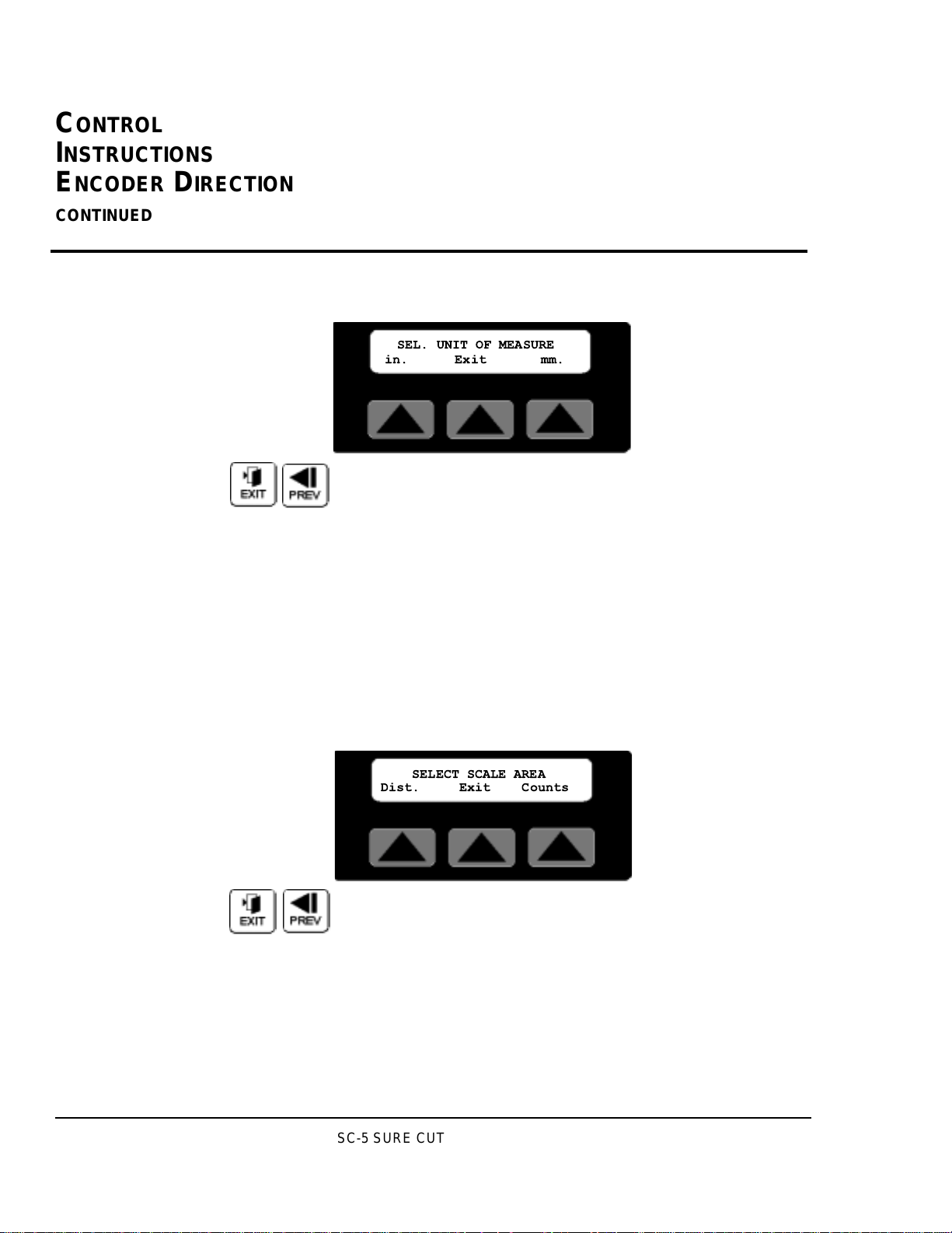
4-22 OPERATION
If a negative symbol is shown to the left of the count value on
the main mode screen the encoder signal is reversed, i.e. rotating in the wrong direction. The Cutter will not function while
the encoder is going negative. The Direction function corrects
this by changing what the servo drive interprets as a positive
direction, CW or CCW rotation.
UNIT OF MEASURE SOFTKEY
By pressing the soft key located under the word U/M on the
Encoder Area screen, the Eng. Units can be set.
Exit or Prev, Pressing Exit or Prev will return the display to
the Encoder Area screen.
in./mm. Softkeys
Pressing the soft key located under in. or mm. Changes all displayed measurements to the respective unit of measure.
The scaled distance must now be set for the desired unit. See
the Scale Area Dist. Softkey description.
Scale Softkey
By pressing the soft key located under the word Scale on the
Encoder Area Screen, there are two sub-menus, Dist., and
Counts accessible. Additional information on how to access
this screen can be found in the Maintenance Area of the operator display overview in Appendix E of this manual.
Exit or Prev, Pressing Exit or Prev will return the display to
the Encoder Area screen.
SETTING THE SCALE FACTOR
The Encoder mode uses a scale factor to compensate for configurations that differ from the standard (a measuring wheel
with a 1 foot circumference; a 3000 bi-directional quadrature
pulse encoder; and English units of measure). The prescale
value is set at the factory for your equipment and typical unit
of measurement. However, it may occasionally be necessary to
adjust the prescale value.
CONTROL
INSTRUCTIONS
UNIT
OF
MEASURE
CONTROL
I
NSTRUCTIONS
ENCODER DIRECTION
CONTINUED
SC-5 SURE CUT Servo Knife Cutter UGE059/1003
SEL. UNIT OF MEASURE
in. Exit mm.
SELECT SCALE AREA
Dist. Exit Counts
Page 57

OPERATION 4-23
UGE059/1003 SC-5 SURE CUT Servo Knife Cutter
CONTROL
INSTRUCTIONS
SCALE
D
ISTANCE
DISTANCE SOFTKEY
By pressing the soft key located under the word Dist. on the
Scale Value Screen, the scaled distance is available. This value
must be set after a U/M change. Additional information on
how to access this screen can be found in the Maintenance
Area of the operator display overview in Appendix E of this
manual.
The number shown is the current distance value, i.e. the circumference of the measuring wheel or distance per revolution
of the encoder. A cursor will appear in the least significant
digit.
Exit or Prev- if no change is required press Exit or Prev to
return to the Scale Value screen.
Raise will increase the value by 0.001inch. The key can be
pressed once for each 0.001inch increment required or held
down to scroll up. Releasing the key will freeze the value at
the last value.
Lower will decrease the value by 0.001inch. The key can be
pressed once for each 0.001inch decrement required or held
down to scroll down. Releasing the key will freeze the value
at the last value.
Numeric keys
Key in the distance desired and press enter. The decimal place
is fixed so remember this when entering the value. If you
require 12.000 inches you must key in 12000 and then press
enter. Keying only 12 will set the distance to 0.012 inches.
Enter or Delete?
If the keyed in number is correct press the enter key for it to
be accepted and return to the Scale Value screen. If it is wrong
press the delete key and the previous value will reappear.
ENTER DISTANCE PER
ENTER DISTANCE PER
COUNTS 12.00 0 in.
COUNTS 12.00 in.
0
Page 58
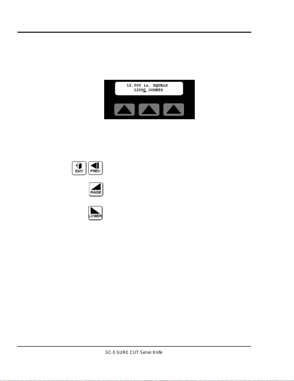
4-24 OPERATION
C
ONTROL
INSTRUCTIONS
SCALE COUNTS
COUNTS SOFTKEY
By pressing the soft key located under the word Counts on the
Scale Value Screen, the scaled counts are available. Additional
information on how to access this screen can be found in the
Maintenance Area of the operator display overview in
Appendix E of this manual.
The number shown is the current count value, i.e. the pulses
per revolution of the encoder. For example a 3000 pulse quadrature encoder will produce 3000 x 4 channels or 12000
counts. A cursor will appear in the least significant digit. The
user has a choice of ways to adjust this number.
Exit or Prev, if no change is required press Exit or Prev to
return to the Scale Value screen.
Raise will increase the value by 1. The key can be pressed
once for each 1 increment required or held down to scroll up.
Releasing the key will freeze the value at the last value.
Lower will decrease the value by 1. The key can be pressed
once for each 1 decrement required or held down to scroll
down. Releasing the key will freeze the value at the last value.
Numeric keys
Key in the count desired and press enter. If you require 12000
counts you must key in 12000 and then press enter.
Enter or Delete?
If the keyed in number is correct press the enter key for it to
be accepted and return to the Scale Value screen. If it is wrong
press the delete key and the previous value will reappear.
SC-5 SURE CUT Servo Knife Cutter UGE059/1003
12.000 in. EQUALS
12000 COUNTS
Page 59
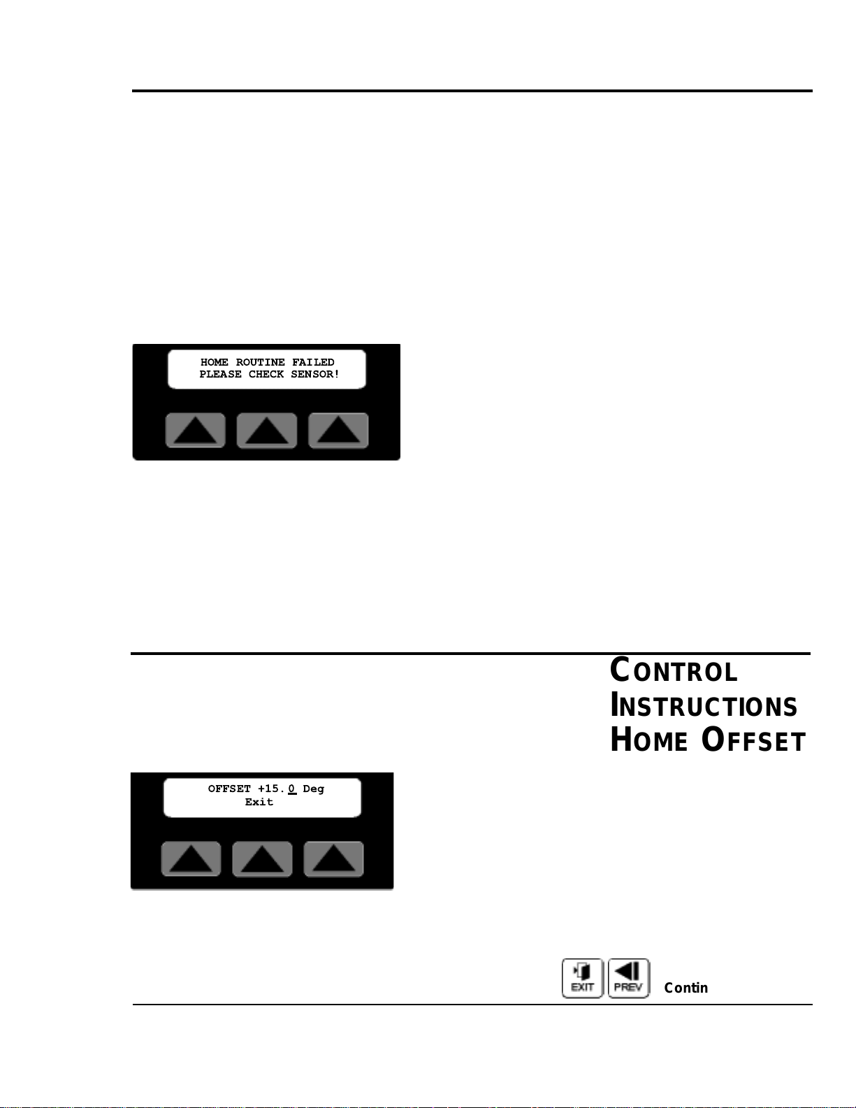
O
PERATION 4-25
UGE059/1003 SC-5 SURE CUT Servo Knife Cutter
CONTROL
INSTRUCTIONS
HOMING
HOMING
A defined Home location is required for all servo-positioning
applications. After initial power up, emergency stop or guard
opened, home position must be found. All motion is relative to
this home position. The Home cycle occurs once after power
is applied to the servo drive in response to the Start push button being pressed. The cutter head rotates towards the home
sensor at the programmed On-Demand blade speed. After the
home sensor has been found, the cutter head will decelerate
and stop at the specified offset position. This position is then
set to 0.0 degrees at the end of the home sequence. If the
home sensor is not found in one revolution of the cutter head,
the following message is displayed on the operator.
The sensor may be faulty, have a loose connection or be
improperly adjusted. Press any key on the operator to
acknowledge the fault. Disconnect power, fix the problem then
restart the cutter.
After a successful home has been completed, if the cutter is
stopped away from the home position and the power to the
machine is left on, the cutter head position is still known.
When the cutter is restarted, the cutter head will return at the
programmed On-Demand blade speed to the home position.
HOME OFFSET SCREEN
By pressing the soft key located under the word Home on the
Maintenance Screen, the offset for the home position is available. Additional information on how to access this screen can
be found in the Maintenance Area of the operator display
overview in Appendix E of this manual.
The number shown is the current offset value, i.e. the distance
from position zero. A cursor will appear in the least significant
digit. The user has a choice of ways to adjust this number.
Exit or Prev, If no change is required press Exit or Prev to
return to the Maintenance Area screen.
C
ONTROL
INSTRUCTIONS
H
OME OFFSET
Continued
HOME ROUTINE FAILED
PLEASE CHECK SENSOR!
OFFSET +15. 0 Deg
Exit
Page 60

4-26 OPERATION
Raise will increase the value by 1.0. The key can be pressed
once for each 1.0 increment required or held down to scroll
up. Releasing the key will freeze the value at the last value.
Lower will decrease the value by 1.0. The key can be pressed
once for each 1.0 decrement required or held down to scroll
down. Releasing the key will freeze the value at the last value.
Numeric keys
Key in the distance desired and press enter. The decimal place
is fixed so remember this when entering the value. If you
require 15.0 degrees you must key in 150 and then press enter.
Keying only 15 will set the distance to 01.5 degrees.
Enter or Delete?
If the keyed in number is correct press the enter key for it to
be accepted and return to the Maintenance Area screen. If it is
wrong press the delete key and the previous value will reappear.
HOME OFFSET EXAMPLE
With the Cut Enable on/off turned off and the cutter started,
entering a new value at the Home Offset screen will initiate a
home routine using the new value.
The graphic example above demonstrates the resulting home
position with a 15 degree offset.
The acceptable range for this value is 00.0 to +45.0 degrees.
Making an entry outside of this range generates the following
error message on the operator display.
After 5 seconds or if any key is pressed the display returns to
the Home Offset
CONTROL
INSTRUCTIONS
OFFSET
EXAMPLE
C
ONTROL
I
NSTRUCTIONS
HOME OFFSET
CONTINUED
SC-5 SURE CUT Servo Knife Cutter UGE059/1003
HOME OFFSET RANGE IS
00.0 TO +45 Deg.
Page 61

OPERATION 4-27
UGE059/1003 SC-5 SURE CUT Servo Knife Cutter
PREVENTIVE MAINTENANCE SOFTKEY
Pressing the soft key located under the word P/M on the
Maint. area screen. Selects the P/M area screen. Three preventive maintenance sub-menus for monitoring Inputs, Time
and Cycles are displayed.
Additional information on how to access this screen can be
found in the Maintenance Area of the operator display
overview in Appendix E of this manual.
Inputs Softkey
Pressing the soft key located under the word Inputs on the
P/M area screen, selects the inputs monitoring screen.
This screen displays the cutters input status. Active inputs are
equal to On and de-energized inputs are equal to Off. This
information could be used for troubleshooting with out the
use of a meter.
Input #1 = End Sense Trigger when On
Input #2 = Run when Off
Input #3 = Manual Cut Trigger when On
Input #4 = Home Registration when On
Input #5 = E-Stop when Off
Input #6 = Spare
Exit or Prev, Pressing Exit or Prev returns the display to the
Select P/M area screen.
CONTROL
INSTRUCTIONS
PREVENTIVE
MAINTENANCE
SELECT P/M AREA
Inputs Time Cycles
I1=Off I2=Off I3=Off
I4=On I5=On I6=Off
Page 62
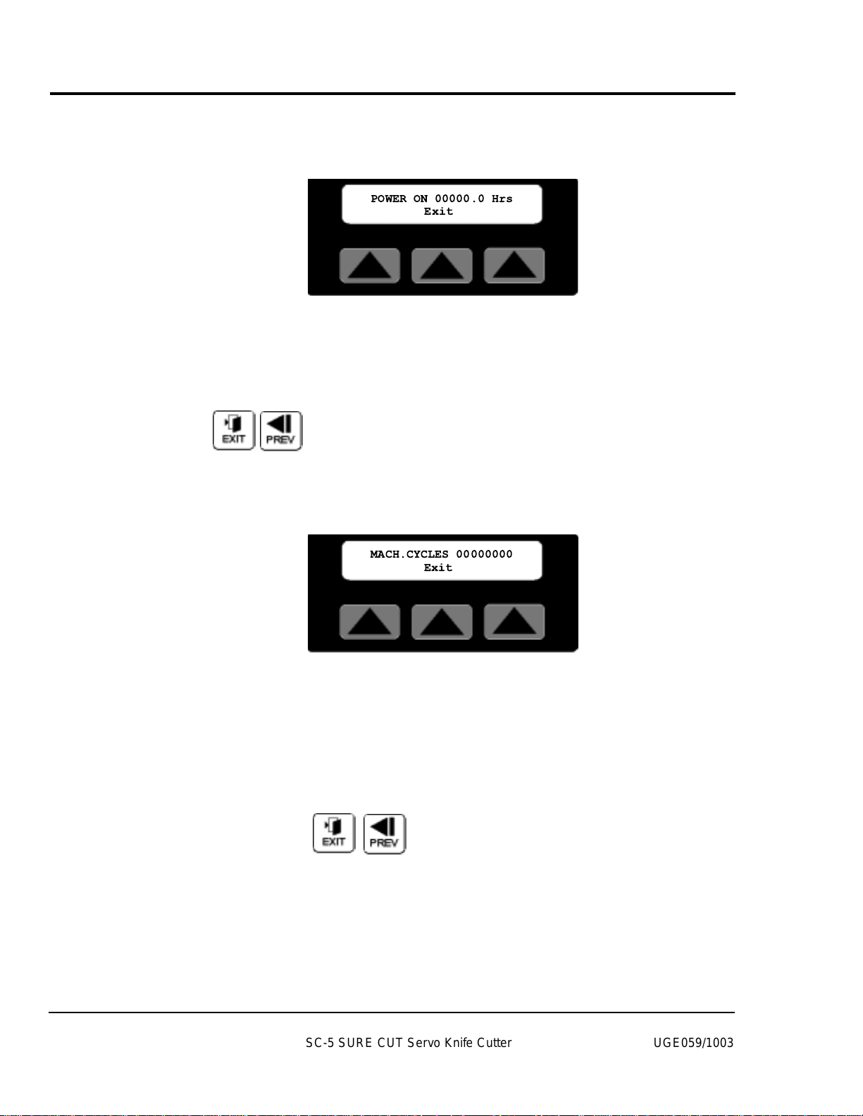
4-28 OPERATION
CONTROL
INSTRUCTIONS
POWER ON TIME
TIME SOFTKEY
Pressing the soft key located under the word Time on the
P/M area screen, selects the Power-On time screen.
The Power-On time screen displays the total time in hours
that the machine has had the power switched on. This information could be used for scheduling preventive maintenance.
The displayed time can not be reset.
Exit or Prev, Pressing Exit, Prev or the Softkey under the
word Exit returns the display to the Select P/M area screen.
Cycles Softkey
Pressing the soft key located under the word Cycles on the
P/M area screen, selects the machine cycles screen.
The Machine Cycles screen displays the absolute total cuts
that the machine has made since manufacture. This information could be used for scheduling preventive maintenance.
The displayed count can not be reset.
Exit or Prev, Pressing Exit, Prev or the Softkey under the
word Exit returns the display to the Select P/M area screen.
SC-5 SURE CUT Servo Knife Cutter UGE059/1003
POWER ON 00000.0 Hrs
Exit
MACH.CYCLES 00000000
Exit
Page 63

UGE059/1003 SC-5 SURE CUT Servo Knife Cutter
Press the manual cut button and observe the
movement of the cutter blade. The cutter head makes a
single rotation and the blade moves through the cutter
bushings without interference.
Insert a piece of extrudate through the cutter bushings.
Press the manual cut button.
A single cut is made
at the preset blade speed. (This works even if Cut On/Off
is off.)
Inspect the cut. If necessary, adjust the blade design
or blade speed. See All About Cutter Blades, Appendix B.
OPERATION 4-29
CHECKING CUT
QUALITY
4
3
2
1
If you have not already done so, check the cutter hardware,
power up the cutter, select cutting mode and blade speed, and
make a test cut to check cut quality.
When you are satisfied with cut quality, press the Cut On/Off
soft key and on is displayed, automatic operation begins.
When the extrudate is running within tolerance, cut it with a
knife or saw and feed it through the cutter bushings.
STARTING THE
SC-5 C
UTTER
Page 64

MAKING
ADJUSTMENTS
DURING
OPERATION
4-30 OPERATION
There are several adjustments you can make during normal
cutting. These adjustments include:
● In Timer mode, adjust the time between cuts
● In Encoder and Follower modes, adjust the length
● In Product mode, adjust the hold-off time
● In Flywheel mode, adjust blade speed
● Adjust blade speed in all modes except
Follower
● Perform a manual cut and reset the length by pressing
the manual cut button at any time during on-demand cutting. Pressing Reset/Test has no effect during continuous
cutting.
● Count the total number of cuts by pressing the Total
On/Off soft key. Use the Reset button to return the count
to zero. This feature is useful for collecting samples during a production run.
● Count the batches of cuts by pressing the Total On/Off
soft key. Use the Reset button to return the count to zero.
This feature is useful for collecting samples during a production run.
● Stop cutting temporarily by setting Cut On/Off to off.
This allows you to view the cutting blade (through the
window) or perform other tasks without shutting down
the cutter.
NOTE:While the controller will allow you to
switch modes during operation, this is not
recommended.
SC-5 SURE CUT Servo Knife Cutter UGE059/1003
Page 65

Use this procedure to safely stop the servo cutter:
Press Cut On/Off soft key to stop cutting (soft key
text changes to off).
Press Stop Cutter button to disable the servo motor
(start light is off).
Turn the rotary disconnect to the off position.
Disconnect the power cord
if it is equipped with
a plug on the end.
Lock out the rotary disconnect.
Clean the lubricant reservoir
if you are shutting
the servo cutter down for the day.
S
TOPPING THE
SC-5 CUTTER
OPERATION 4-31
WARNING: Never stop the servo cutter by opening the knife guard.
This can cause damage to the equipment and
injury to personnel.
WARNING: Never turn off the rotary
disconnect first.
Doing so will turn off all power to the unit, and
the cutter will not be brought to a controlled
stop.For safe stopping, always follow the
sequence given above.
1
2
3
4
5
6
UGE059/1003 SC-5 SURE CUT Servo Knife Cutter
Page 66

Page 67

5-1
UGE059/1003 SC-5 SURE CUT Servo Knife Cutter
●●
Maintenance Features . . . . . . . .5-2
●●
Warnings and Cautions . . . . . . .5-2
●●
Maintenance Overview . . . . . . .5-4
●●
Preventative Maintenance
Schedule . . . . . . . . . . . . . . . . .5-4
●●
Checking the Blades . . . . . . . . .5-6
●●
Inspecting Cutter
Bushing Screws . . . . . . . . . . .5-7
●●
Checking the Closure Latch . . .5-7
●●
Cleaning the Blade Tray . . . . . . .5-8
●●
Lubricating the Slide
Rail System . . . . . . . . . . . . . . .5-8
●●
Adjusting the
Proximity Switches . . . . . . . . .5-9
●●
Checking Electrical
Connections . . . . . . . . . . . . .5-10
●●
BLoc Installation and
Removal . . . . . . . . . . . . . . . . .5-12
MAINTENANCE
Page 68

W
ARNINGS AND
CAUTIONS
The Servo Cutter SC-5 Sure Cut models needs regular, scheduled maintenance for peak performance. Among the features
that require maintenance are:
● Cutter blades
● Blade mounting hardware
● Cutter bushings
● The knife guard hardware
● Cutter alignment
● Floor locks
● Lubrication tray
● Shafts of optional slide rail system
● Electrical cables
● Control panel lights
MAINTENANCE
FEATURES
SC-5 SURE CUT Servo Knife Cutter UGE059/1003
5-2 MAINTENANCE
To maintain the best performance of the servo cutter, it must
be cleaned and inspected regularly. Maintenance includes a
daily, weekly, quarterly, and semi-annual (every 6 months)
schedule.
Use this maintenance schedule as a guide. You may need to
shorten the time of the maintenance schedule, depending on
how often you use the servo cutter, and the types of material
flowing through it.
Follow all precautions and warnings when working on the
equipment.
WARNING: Improper installation,
operation, or servicing may result in
equipment damage or personal injury.
This equipment should only be installed, adjusted, and serviced by qualified technical personnel who are familiar with the construction, operation, and potential hazards of this type of
machine.
All wiring, disconnects, and fuses should be
installed by qualified electrical technicians in
accordance with electrical codes in your region.
Continued
Page 69
UGE059/1003 SC-5 SURE CUT Servo Knife Cutter
MAINTENANCE 5-3
WARNING:Voltage Hazard
This equipment is powered by alternating current, as specified on the machine serial tag and
data plate. Do not operate the equipment at
power levels other than what is specified on the
machine serial tag and data plate.
A properly-sized conductive ground wire from
the incoming power supply must be connected
to the chassis ground terminal inside the electrical enclosure. Improper grounding can result in
severe personal injury and erratic machine
operation.
LOCKOUT/TAGOUT:
Before performing maintenance or repairs on
this product, disconnect and lock out electrical
power sources to prevent injur y from unexpected energization or start-up. A lockable disconnect device has been provided to isolate this
product from potentially hazardous electricity.
DANGER: Sharp blades!
Most injuries caused by knife blades occur
when the cutter has been turned off. Handle
blades with care at all times.
● Always wear cut-resistant gloves when the
cutting chamber is open and when handling
blades.
● Always lock out the cutter before opening the
cutting chamber.(See Lockout/tagout above)
● Always wait until the cutter head has stopped
completely before opening the knife guard.
SC-5 Sure Cut cutters are equipped with several safety devices to ensure safe operation.
Never remove or disable these devices to sustain production. Operating without these devices
can cause severe injury.
● When the knife guard is opened, the knife
guard switch stops the cutter but does not
remove powder from the drive.
● Two proximity-type safety switches prevent
operation unless the cutter bushings are in
place.
● The STOP button activates a circuit that
stops the knife.
WARNINGS AND
CAUTIONS
C
ONTINUED
Page 70

This section describes the daily, weekly, monthly and semiannual maintenance schedules that should be performed when
changing materials or lines, or when changing equipment, as
well as the maintenance procedures to follow.
Cutting either flexible or rigid materials generates tremendous
shock and vibration to the entire unit. Anything that can
loosen, will over time.
To maintain the best performance, follow this maintenance
schedule and develop an effective preventative maintenance
program.
●
Daily
❒❒
Checking cutter blade(s)
Clean, sharpen or replace as needed (see Checking the
Blades, Section 5).
❒❒
Inspecting the blade mounting hardware
The blade securing bolt should use both a lock washer
and flat washer, and be tightened enough to fully compress the lock washer. Replace the holding pins if they
appear worn.
❒❒
Inspecting the cutter bushing screws
Check that the cutter bushing screws are secure (see
Inspecting Cutter Bushing Screws, Section 5).
❒❒
Checking the closure latch on the knife guard
See Checking the Closure Latch, Section 5.
❒❒
Inspecting cutter alignment
Proper cutter alignment is critical for optimum performance. Use a plumb line or laser to check for a
straight line from the extrusion die to the cutter bushings.
❒❒
Check floor locks
It is always recommended that the weight be removed
from the casters for optimum stability during cutting
cycles. Check to see if the floor locking mechanism is
properly adjusted.
SC-5 SURE CUT Servo Knife Cutter UGE059/1003
5-4 MAINTENANCE
MAINTENANCE
OVERVIEW
PREVENTATIVE
M
AINTENANCE
SCHEDULE
Continued
Page 71
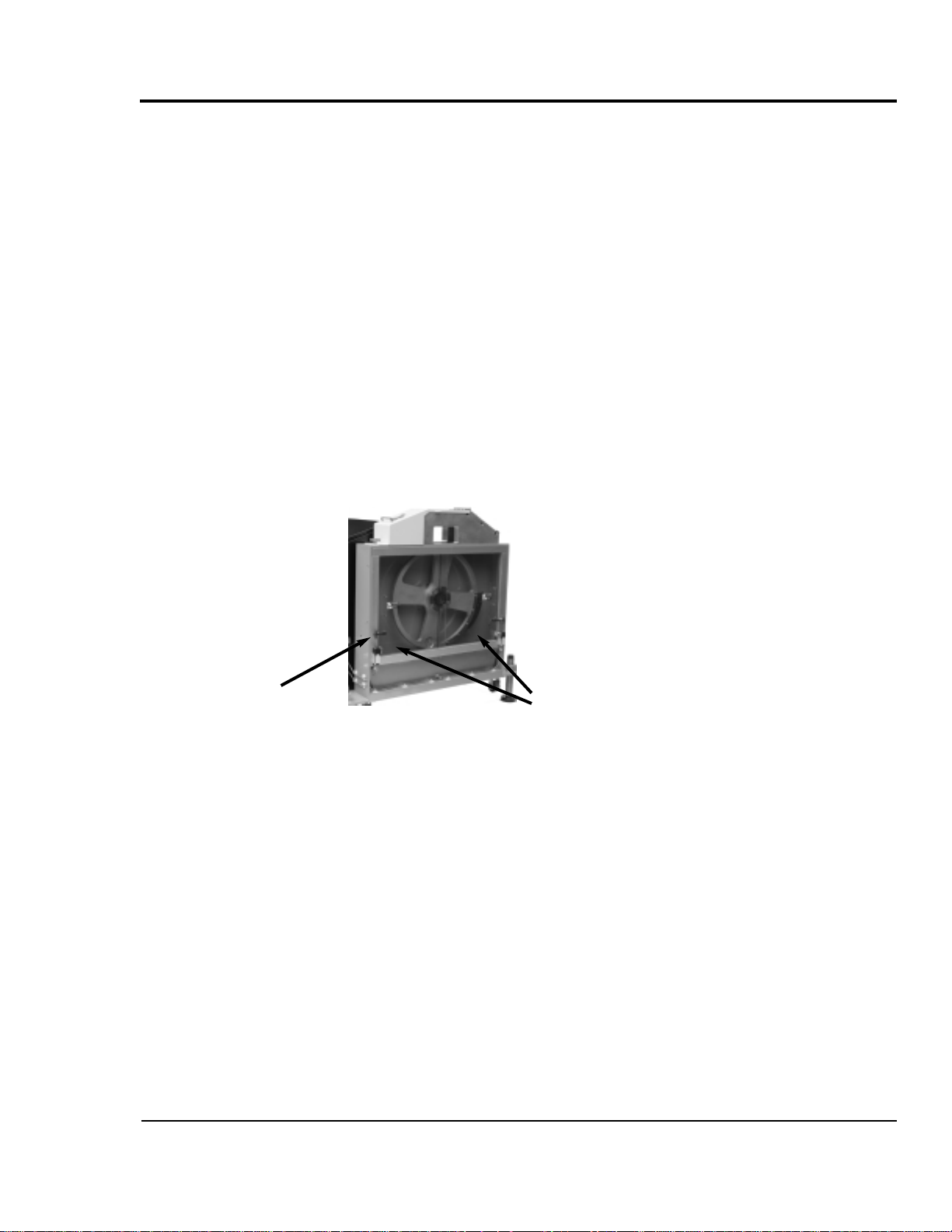
● Weekly
❒❒
Cleaning the blade lubrication tray (if the cutter
has this option). See Cleaning the Blade Tray,
Section 5.
❒❒
Lubricating shafts on optional slide rail system
See Cleaning the Blade Tray, Section 5.
●
Monthly
❒❒
Checking hardware on the knife guard
Inspect the hardware on the knife guard (fasteners on
hinge and the clear blade guard window). Tighten as
needed.
❒❒
Checking bushing holder proximity switches
Inspect the sets screws which retain the bushing holder
proximity switches for tightness. Adjust as needed. See
Adjusting the Proximity Switches, Section 5.
❒❒
Checking the draw latch
Inspect the latch on knife guard windows for wear and
PREVENTATIVE
MAINTENANCE
SCHEDULE
C
ONTINUED
UGE059/1003 SC-5 SURE CUT Servo Knife Cutter
MAINTENANCE 5-5
❒❒
Clean the clear blade guard window
Clean using glass cleaner or plain water. Other materials may cause premature loss of clarity or crazing.
●
Semi-annual (every 6 months)
❒❒
Inspecting electrical terminals
Check all electrical terminals for tightness; adjust as
needed. See Checking Electrical Connections, Section
5.
❒❒
Checking torque on Trantorque coupling device
Check the tightness (torque) of the Trantorque coupling
device with a torque gauge. This device connects the
cutter head to the Micron reducer shaft. See Checking
Torque, Section 5.
❒❒
Checking all electrical cables
Inspect all electrical cables for cuts and abrasions.
Replace as needed.
❒❒
Inspecting control panel lights
Check to make sure no LEDs or lights are burned out
on the control panel. Replace as needed.
Draw Latch
Clear Guard Windows
Page 72
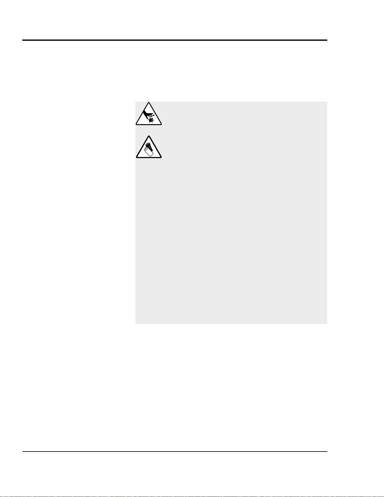
Blades become dull over time depending on the material being
cut, cut rate, blade speed, and blade material and thickness.
Check blades regularly for sharpness as well as scratches,
nicks, burrs, and material buildup. Clean, sharpen or replace
as needed (see Installing Cutter Blades, Section 3).
CHECKING
BLADES
SC-5 SURE CUT Servo Knife Cutter UGE059/1003
5-6 MAINTENANCE
DANGER: Sharp blades!
Most injuries caused by knife blades occur
when the cutter has been turned off. Handle
blades with care at all times.
● Always wear cut-resistant gloves when the
cutting chamber is open and when handling
blades.
● Always lock out the cutter before opening the
cutting chamber.
● Always wait until the cutter head has stopped
completely before opening the knife guard.
SC-5 Sure Cut cutters are equipped with several safety devices to ensure safe operation.
Never remove or disable these devices to sustain production. Operating without these devices
can cause severe injury.
● When the knife guard is opened, the knife
guard switch stops the cutter and prevents
starting the cutter again.
● Two proximity-type safety switches prevent
operation unless the cutter bushings are in
place.
● The STOP button activates a circuit that
stops the knife.
Page 73

UGE059/1003 SC-5 SURE CUT Servo Knife Cutter
MAINTENANCE 5-7
Check the set screws that secure the cutter bushings. If bushings move during cutting, cutting blades and possibly the
drive chain could be damaged.
INSPECTING
CUTTER
BUSHING
SCREWS
CHECKING THE
KNIFE
GUARD
Check the hand knob and tighten it so the knife guard closes
completely. This prevents false triggering of the safety switch.
Cutter
bushing
screws
Hand knob
Page 74
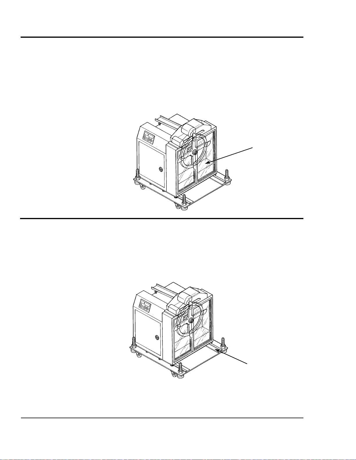
SC-5 SURE CUT Servo Knife Cutter UGE059/1003
5-8 MAINTENANCE
This tray is built into the cutter assembly as a simple method
of applying lubrication to your blade during cutting cycles.
Depending on cut rate and type of material and lubrication,
the area will need to be cleaned on a regular basis and the
lubricant replaced. Open the clear guard windows and, using a
shop vac or other similar equipment, remove all liquid and
solids from the cutting chamber and around the bushings.
Replace the lubricant. For more information, see Blade and
Bushing Lubrication, Appendix D.
CLEANING THE
BLADE TRAY
(OPTIONAL)
Check the shafts on the slide rail system. Even though these
shafts are stainless steel, it is recommended that a light oil
(WD-40 or similar) be applied to the shafts as needed. Wipe
off any excess.
LUBRICATING
THE
SLIDE RAIL
S
YSTEM
(OPTIONAL)
Optional blade
lubrication system
Optional slide base
assembly with position locking mechanism
Page 75
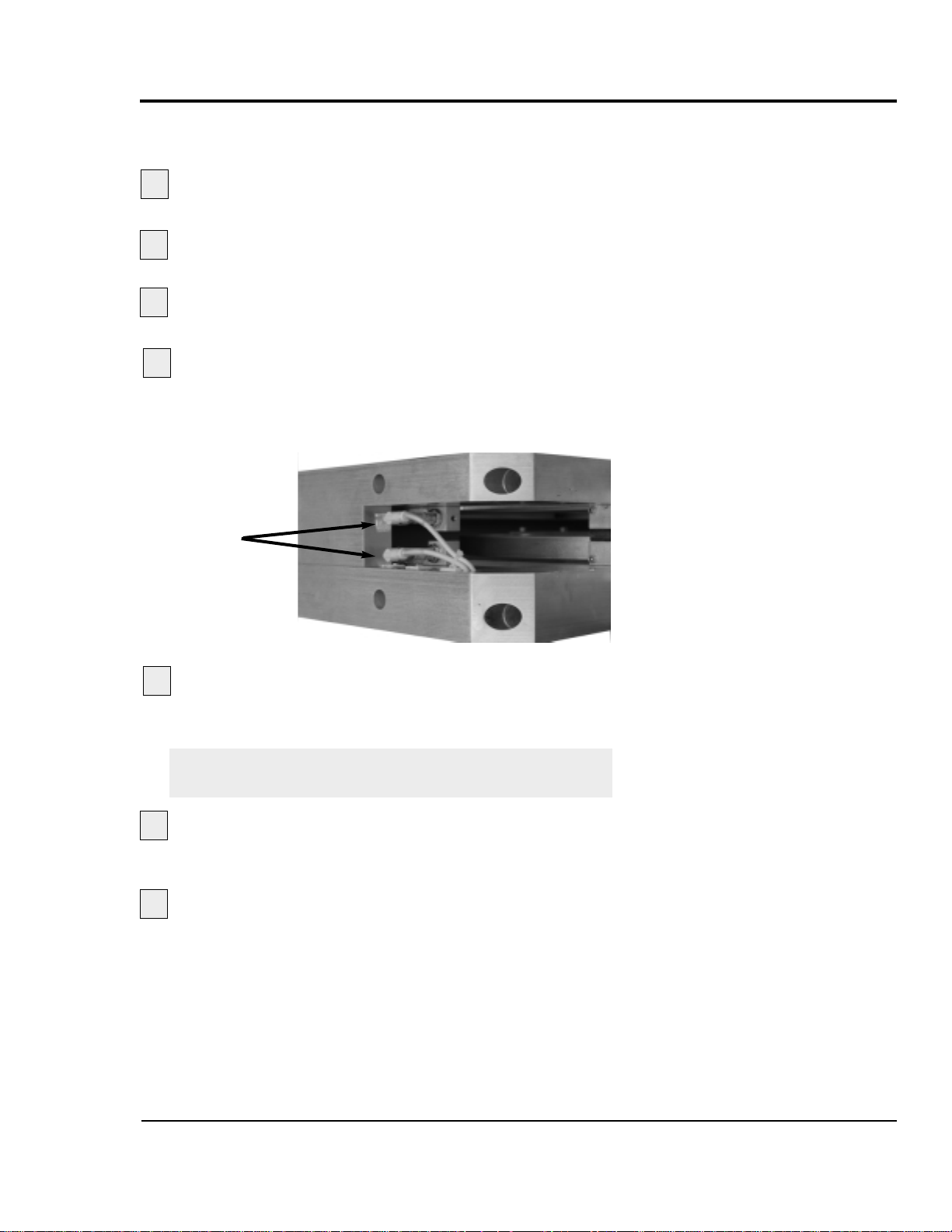
Follow all warnings and cautions listed at the beginning of the
Maintenance section of this User Guide.
Be sure the main power is disconnected and the
cutter is locked out.
Loosen the set screws that hold the cutter bushings.
Remove the cutter bushings.
Check the depth of the proximity switch
face for each bushing
. It should be recessed no more
than 0.010 inches, but should not interfere with the bushings themselves.
Check the tightness
of each proximity switch's
retaining screw. Use an Allen wrench to perform this
task.
IMPORTANT:You can damage the proximity switch if
you over-tighten the retaining screw.
Replace cutter bushings and check for proper cut-
ting blade alignment. See Mounting the Cutter Bushings,
Section 3 and the Appendix A and C.
Plug in the power cord and turn the main power dis-
connect to the on position if all other maintenance is completed.
ADJUSTING THE
PROXIMITY
SWITCHES
UGE059/1003 SC-5 SURE CUT Servo Knife Cutter
MAINTENANCE 5-9
2
1
3
4
6
7
5
Proximity
switches
Page 76

Be sure the main power is disconnected and
the cutter is locked out
. Always disconnect and
lock out the main power source before opening the unit or
servicing.
Turn the main power disconnect to the off
position
before opening the electrical enclosure on the
back of the cutter, or the back of the control. This is a
safety device to prevent you from opening the doors if the
power is still on.
CHECKING
ELECTRICAL
CONNECTIONS
SC-5 SURE CUT Servo Knife Cutter UGE059/1003
5-10 MAINTENANCE
WARNING: Electrical hazard
Before performing any work on this product,
disconnect and lock out electrical power
sources to prevent injury from unexpected energization or start-up. A lockable device has been
provided to isolate this product from potentially
hazardous electricity.
WARNING: Improper installation, operation, or servicing may result in
equipment damage or personal injury.
This equipment should only be installed, adjusted, and serviced by qualified technical personnel who are familiar with the construction, operation, and potential hazards of this type of
machine.
All wiring, disconnects, and fuses should be
installed by qualified electrical technicians in
accordance with electrical codes in your region.
Always maintain a safe ground. Do not operate
the equipment at power levels other than what
is specified on the machine serial tag and data
plate.
1
2
Main power
safety disconnect
Continued
Page 77

Open the electrical enclosure.
Inspect all wires and connections
. Look for loose
wires, burned contacts, and signs of over-heated wires.
Have a qualified electrician make any necessary repairs or
replacements.
Close the electrical enclosure door.
Inspect the exterior power cords.
Cords should
not be crimped, exposed, or rubbing against the frame. If
the main power cord runs along the floor, make sure it is
not positioned where it could rest in pooling water or
could be run over and cut by wheels or casters.
UGE059/1003 SC-5 SURE CUT Servo Knife Cutter
MAINTENANCE 5-11
3
4
5
6
CHECKING
ELECTRICAL
CONNECTIONS
C
ONTINUED
Page 78
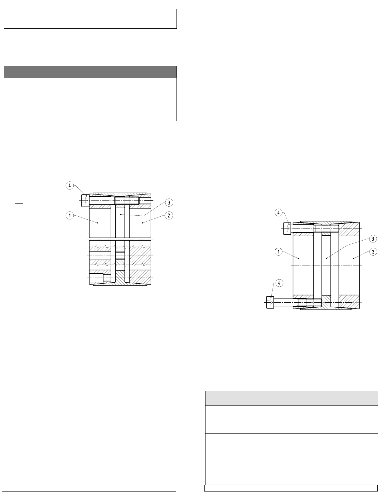
INSTALLATION AND REMOVAL INSTRUCTIONS FOR
B-LOC™ LOCKING ASSEMBLY SERIES B112
Thank you for purchasing a B-LOC™ Keyless Frictional Locking Device.
B-LOC™ keyless connectors provide a high capacity, zero-backlash
shaft/hub or coupling connection by means of a mechanical interference
fit. Please follow these INST ALLA TION AND REMOVAL INSTRUCTIONS
carefully to ensure proper performance of this B-LOC™ unit.
! WARNING !
When installing or removing B-LOC™ products, always adhere to the following
safety standards:
1. Be sure that all power switches are locked out before installing or removing
B-LOC™ products.
2. Eye protection is required when installing or removing B-LOC™ products
- please wear safety glasses and protective clothing.
INSTINST
ALLAALLA
ALLA
ALLAALLA
TIONTION
TION
TIONTION
Figure 1
INST
INSTINST
(Refer to Figures 1 and 2)
B-LOC™ Locking Assemblies are supplied lightly oiled and ready for installation. When reinstalling a used unit, make sure that all slits are aligned and
that front and rear clamp collars are not reversed (when assembled correctly
there are no holes or threads behind taps in clamp collar Item 1, and no threads
behind taps in center collar Item 3). The frictional torque capacity of these
devices is based on a coefficient of friction of 0.12 for lightly oiled screw,
taper, shaft and bore
contact areas.
Therefore, it is important
not to use Molybdenum Disulfide (e.g.,
Molykote, Never-Seeze
or similar lubricants) in
any Locking Assembly
installation.
1. Make sure that lock-
ing screw, taper,
shaft and bore contact areas are clean
and lightly oiled and
that all collar slits are
aligned.
2. Loosen all locking
screws by a minimum of four (4) turns and transfer at least two (2) screws
to push-off threads in clamp collar Item 1 to disengage this part from
center collar Item 3. Similarly, transfer at least two (2) screws to push-off
threads in center collar Item 3 to disengage this part from clamp collar
Item 2 (see Figure 2).
3. Completed assembly can now be placed on shaft and inserted into hub
bore by pushing against face of collar Item 1 while ensuring that collar
Item 2 is not engaged at tapers during this phase.
4. After placement of Locking Assembly, relocate locking screws used for
separation of collars.
5. Hand tighten connection and confirm that clamp collar Item 1 is parallel
with face of part to be attached to shaft and/or with the front facing edge of
center collar Item 3.
6. Use torque wrench and set it approximately 5% higher than specified tight-
ening torque MA. Tighten locking screws in either a clockwise or counterclockwise sequence (it is not necessary to tighten in a diametrically opposite pattern), using only 1/4 (i.e., 90°) turns for several passes until 1/4
turns can no longer be achieved.
7. Continue to apply overtorque for 1 to 2 more passes. This is required to
compensate for a system-related relaxation of locking screws since
tightening of a given screw will always relax adjacent screws. Without
overtorquing, an infinite number of passes would be needed to reach
specified tightening torque.
8. Reset torque wrench to specified torque (MA) and check all locking screws.
No screw should turn at this point, otherwise repeat Step 7 for 1 or 2 more
passes. It is not necessary to re-check tightening torque after equipment
has been in operation.
B-LOC Corporation 26 Gilbert Street Monroe, NY 10950 For technical assistance, please call 1-800-865-7756
NOTE: In installations subjected to extreme corrosion, the slits in clamp
The Locking Assembly should be positioned so that slits in Locking Assembly
collars that contact the shaft are located approximately opposite the keyway.
In addition, a locking screw should be centered directly over the keyway.
When tightening locking screws, it is important to follow the installation procedure outlined above, which specifies equal 1/4 turns of each locking screw.
Failure to follow these instructions could result in excessive tightening of the
screw over the keyway, possibly causing permanent deformation of the Locking Assembly collars. Even after 1/4 turns can no longer be achieved, it is
important to continue to use equal turning angles for every screw until the
specified tightening torque is reached.
IMPORTANT! Make sure ends of locking screws used for removal are
1. Check to ensure that axial movement of clamp collars - necessary for
2. Remove all locking
3. Release collar Item 1
4. Transfer locking screws used for dismounting of clamp collar Item 1 into
collars Item 1 and Item 2, as well as in center collars, should be
sealed with a suitable caulking compound or equivalent. Likewise,
push-off threads should also be protected from corrosion.
INSTINST
ALLAALLA
INST
INSTINST
ASSEMBLIES OASSEMBLIES O
ASSEMBLIES O
ASSEMBLIES OASSEMBLIES O
Prior to initiating the following removal procedure, check to ensure that
no torque or thrust loads are acting on the Locking Assembly, shaft or
ground flat and are slightly chamfered to prevent damage
to screw and collar threads during push-off.
release of connection - is not restricted. Likewise, ensure that push-off
threads are in good
condition.
screws. Transfer required number of
screws into all pushoff threads of clamp
collar Item 1 (see
Figure 2).
by progressively tightening all push-off
screws. Typically , the
push-off screws appear to be completely
tight after just one
pass of tightening
without any noticeable separation of clamp collars. Although it seems that the screws cannot
be tightened further, several more rounds of torquing in either a clockwise or
counterclockwise sequence will increase the push-off force in the system and
ultimately release part of the front collar. Afterwards, only the screws which
are still tight should be tightened further until complete dismounting is achieved.
Remove clamp collar Item 1.
all push-off threads in center collar Item 3 (see Figure 2). Release clamp
collar Item 2 by repeating procedures outlined in Step 3.
LOCKING SCREW SIZES AND SPECIFIED TIGHTENING TORQUE M
Metric Series
25 x 55 to 35 x 60 1 to 1-7/16 12 M 6 5
40 x 75 to 65 x 95 1-1/2 to 2-9/16 30 M 8 6
70 x 110 to 90 x 130 2-5/8 to 3-5/8 60 M10 8
100 x 145 to 120 x 165 3-3/4 to 4-3/4 105 M12 10
130 x 180 to 160 x 210 4-15/16 to 6 166 M14 12
170 x 225 to 260 x 325 6-7/16 to 8 257 M16 14
280 x 355 to 340 x 425 500 M20 17
360 x 455 to 600 x 695 675 M22 17
TION OF TION OF
ALLA
TION OF
ALLAALLA
TION OF TION OF
(Refer to Figure 2)
any mounted components.
B112 LOCKING ASSEMBLY
B-LB-L
OC™OC™
L L
B-L
OC™
B-LB-L
VER SHAFT KEYWVER SHAFT KEYW
VER SHAFT KEYW
VER SHAFT KEYWVER SHAFT KEYW
REMOREMO
REMO
REMOREMO
Inch Series
OC™OC™
VV
ALAL
V
AL
VV
ALAL
OCKINGOCKING
L
OCKING
L L
OCKINGOCKING
Tightening
Torque
M
A
(ft-lbs)
AA
YY
SS
A
Y
S
AA
YY
SS
Figure 2
Screw
Size
A
Hex
Key
Size
(mm)
Page 79

6-1
UGE059/1003 SC-5 SURE CUT Servo Knife Cutter
●●
Before Beginning . . . . . . . . . . . .6-2
●●
A Few Words of Caution . . . . . .6-2
●●
Identifying the
Cause of a Problem . . . . . . . . .6-3
●●
Electrical Problems . . . . . . . . . .6-4
●●
Product Quality Problems . . . . .6-8
Repair
●●
Replacing Safety and
Proximity Switches . . . . . . . .6-12
●●
Checking the
Servo Amplifier . . . . . . . . . . .6-12
●●
Adjusting the
Proximity Switches . . . . . . . .6-14
●●
Checking the Encoder . . . . . . .6-15
●●
Checking the Motor/
Reducer Assembly . . . . . . . . .6-17
●●
Checking Repeatability . . . . . .6-18
TROUBLESHOOTING
Page 80

You can avoid most problems by following the recommended
installation, operation and maintenance procedures outlined in
this User Guide. If you have a problem, this section will help
you determine the cause and tell you how to fix it.
Find any wiring, parts, and assembly diagrams that were
shipped with your equipment. These are the best reference for
correcting a problem. The diagrams will note any custom features or options not covered in this User Guide.
Verify that you have all instructional materials related to the
servo knife cutter. Additional details about troubleshooting
and repairing specific components are found in these materials.
Check that you have manual for other equipment connected in
the system. Troubleshooting may require investigating other
equipment attached to, or connected with the cutter.
BEFORE
BEGINNING
SC-5 SURE CUT Servo Knife Cutter UGE059/1003
6-2 TROUBLESHOOTING
A F
EW WORDS
OF
CAUTION
WARNING: Improper installation, operation, or servicing may result in
equipment damage or personal injury.
This equipment should only be installed, adjusted, and serviced by qualified technical personnel who are familiar with the construction, operation, and potential hazards of this type of
machine.
All wiring, disconnects, and fuses should be
installed and adjusted by qualified electrical
technicians in accordance with electrical codes
in your region. Always maintain a safe ground.
Do not operate the equipment at power levels
other than what is specified on the machine
serial tag and data plate.
WARNING: Electrical hazard
Before performing maintenance or repairs on
this product, disconnect and lock out electrical
power sources to prevent injur y from unexpected energization or start-up. A lockable device
has been provided to isolate this product from
potentially hazardous electricity.
Continued
Page 81

The Troubleshooting section covers problems directly related
to the operation and maintenance of the servo cutter. This section does not provide solutions to problems that originate with
other equipment. Additional troubleshooting help can be
found in manuals supplied with the other equipment.
The main problems you will see with the servo cutter are:
● Cutter operation problems, which focus on problems
that are clearly related to the operation of the cutter’s
electrical control systems.
● Plastic product quality concerns, which deal with prod-
uct characteristics that may be related to cutter operation.
Of course, other sections of the extrusion line also influence the quality of the extruded product. This section
does not provide solutions to problems originating with
other equipment on the extrusion line.
Additional troubleshooting help can be found in the manufacturer’s manuals included with this User Guide.
IDENTIFYING THE
CAUSE OF A
PROBLEM
UGE059/1003 SC-5 SURE CUT Servo Knife Cutter
TROUBLESHOOTING 6-3
DANGER: Sharp blades!
Most injuries caused by knife blades occur
when the cutter has been turned off. Handle
blades with care at all times.
● Always wear cut-resistant gloves when the
cutting chamber is open and when handling
blades.
● Always lock out power to the cutter before
opening the cutting chamber.
● Always wait until the cutter head has stopped
completely before opening the knife guard.
SC-5 Sure Cut cutters are equipped with several
safety devices to ensure safe operation. Never
remove or disable these devices to sustain production. Operating without these devices can
cause severe injury.
● When the knife guard is opened, the knife
guard switch stops the cutter and prevents
starting the cutter again.
● Two proximity-type safety switches prevent
operation unless the cutter bushings are in
place.
● The STOP button activates a circuit that
stops the knife.
A F
EW WORDS
OF
CAUTION
C
ONTINUED
Page 82

SC-5 SURE CUT Servo Knife Cutter UGE059/1003
6-4 TROUBLESHOOTING
ELECTRICAL
PROBLEMS
Look in this section when you have problems such as lights on
the control that are working improperly, buttons that do not
execute the function properly, and when information input is
not executed properly.
Symptom
◆ The green start
button does not
illuminate when
pressed
◆ Pressing the cut
enable soft key and
cutter does not
start cutting
◆ Pressing the
Reset/Test button
does not produce a
cut when in an ondemand mode.
P ossible cause
The E-stop button is
pushed in.
A safety switch has failed.
There is a loose connection.
The relay is bad.
The guard circuit failed.
The servo amplifier is not
in Program mode.
There is a loose connection.
Solution
Pull out the E-stop button.
Check to see if:
❒ The blade guard is closed.
❒ Master Control relay
(MCR) has failed. Replace
relay.
Check connections and replace
if needed.
Check wiring between cutter
control and the relay.
Repair or replace the relay.
Check guard circuit, repair or
replace components.
Check servo, if necessary,
reboot main power.
Check wiring and tighten connection.
Page 83

UGE059/1003 SC-5 SURE CUT Servo Knife Cutter
TROUBLESHOOTING 6-5
Symptom
◆ After pressing
Start Cutter, the
cutter head rotates
slowly but does not
stop.
◆ Master safety
relay does not energize
◆ While in
Encoder mode, no
count is displayed
Possible cause
The Blade home proximity switch failed or the
connection to it is loose.
Guard circuit is open.
Input from encoder
failed.
Encoder failed.
Solution
Check connections and replace
switch if needed.
Check to see if:
❒ The blade guard is closed.
❒ Loose connection to guard
circuit. Tighten connection.
❒ Guard switch is bad.
Replace switch.
Check encoder cable for continuity. Connect any loose wires.
Replace encoder.
ELECTRICAL
PROBLEMS
C
ONTINUED
Page 84

ELECTRICAL
PROBLEMS
C
ONTINUED
SC-5 SURE CUT Servo Knife Cutter UGE059/1003
6-6 TROUBLESHOOTING
Symptom
◆ In encoder or
timer modes, the
display shows the
count which resets,
but a cut does not
occur at the point
of reset.
◆ Cutter stops and
nothing is displayed
Possible cause
There is a problem with
the cutter control.
There is a problem with
the servo amplifier.
There is a loose connection.
There is an anti-jam circuit signal.
There is a problem with
the home proximity
switch.
Solution
Check for control output.
See Checking the Servo
Amplifier.
Check wiring for loose connections.
This error appears when the
blade does not go through the
cut cycle in the required time.
Check for:
❒ Loose connection on cutter
control or servo amplifier.
❒ Fault on Amplifier prevent-
ing cut cycle.
❒ Blade is stuck in extrudate/
bushings.
❒ Look at the drive and
record the fault code and
call the Conair service
department.
See Adjusting the Proximity
Switches, Section 5.
Page 85

UGE059/1003 SC-5 SURE CUT Servo Knife Cutter
TROUBLESHOOTING 6-7
Symptom
◆ Blade speed does
not change when new
speed is entered into
the control.
◆ Cutter mode selec-
tion does not change
cut mode.
◆ The park (home)
position is drifting,
i.e. the blade parks
further away from
the original park site.
Possible cause
There is a communication
failure between the control and drive.
There is a communication
failure between the control and drive.
The coupling between the
servo motor and the
Micron reducer has
slipped.
The Trantorque coupling
has slipped.
Solution
Check for wiring for loose
connections and tighten.
Check for wiring for loose
connections and tighten.
See Checking the Motor/
reducer assembly, Section 6.
Refer to the Trantorque
instructions, Section 5.
ELECTRICAL
PROBLEMS
C
ONTINUED
Page 86

SC-5 SURE CUT Servo Knife Cutter UGE059/1003
6-8 TROUBLESHOOTING
Look in this section when the final product does not meet
standards: has strings, burrs, cracks, or is misshaped.
Symptom
◆ Hairs or strings.
Possible cause
Blade speed is too low.
The blade is too thick.
The blade is wrong for
the application.
Material is building up
on the blade and wiping
off on the cut site.
There are imperfections
on the blade.
A hole or slot in the blade
cut path is causing a
‘cheese grater’ effect.
The extrudate is too cold.
Solution
Increase the blade speed or
decrease the blade cut path
area (blade width)
Excessive blade thickness can
cause frictional heat. Use a
thinner blade.
Change angle of the blade
attack or the blade style to
decrease the cut path area.
Use blade lubrication (water,
etc.) or change lubricants.
Consider a blade wiping system.
The cutting edge should not
have grind marks, burrs or
other imperfections. Check the
blade and replace if necessary.
Change blade design.
If the extrudate is too cold, it
can fracture during cutting.
Raise the extrudate's temperature.
PRODUCT
QUALITY
PROBLEMS
Page 87

UGE059/1003 SC-5 SURE CUT Servo Knife Cutter
TROUBLESHOOTING 6-9
Symptom
◆ Burrs at cut site.
Possible cause
The bushings are not providing enough support
during cutting.
The bushing gap is too
wide.
The blade speed is too
low.
Solution
Change bushing design to
make them more supportive.
The bushing gap should be no
more than .001-.003 inch larger than the blade. Check and
adjust if necessary.
Low blade speeds can cause
excessive blade interruption.
Increase blade speed or
decrease the blade cut path
area.
PRODUCT
QUALITY
PROBLEMS
C
ONTINUED
Page 88

SC-5 SURE CUT Servo Knife Cutter UGE059/1003
6-10 TROUBLESHOOTING
Symptom
◆ Cracks at cut
site.
Possible cause
The extrudate is too cold.
The blade speed is too
high.
The bushings are not providing enough support
during cutting.
The cutting blade is too
sharp.
If using Nylon, it may be
cooling too quickly.
Solution
If the extrudate is too cold, it
can fracture or whiten during
cutting. Raise the extrudate's
temperature.
High blade speeds can cause
too much impact. Lower the
blade speed.
Change the bushing design to
make them more supportive.
A blade that is too sharp can
fracture some materials, especially rigid PVC and nylons.
Slightly dull the blade.
If nylon is cooled too quickly,
its molecular structure may
become unstable, leading to
poor physical properties. Try
more gradual cooling.
PRODUCT
QUALITY
PROBLEMS
C
ONTINUED
Page 89

UGE059/1003 SC-5 SURE CUT Servo Knife Cutter
TROUBLESHOOTING 6-11
Symptom
◆ Cut is not square.
Possible cause
The blade speed is too
low.
The blade is misaligned.
The cutter bushings are
not properly gapped.
The knife bevel is not
symmetric.
For rigid products the
puller is too close to the
cutter.
Solution
Low blade speeds can cause
excessive blade interruption.
Increase blade speed or
decrease the blade cut path
area.
Check that blade is 90 degrees
relative to the bushing holder.
If the cutter bushings are not
properly gapped, the blade
may be free to move with the
extrudate. Check and adjust if
necessary . See Appendix A.
If the knife bevel is asymmetric, the blade will tend to move
in the direction of the smaller
bevel. Be sure that the bevel is
symmetric. NOTE: You can
use this to your advantage with
some rigid products.
There must be enough space
between the puller and cutter
to allow for extrudate stoppage
that occurs during cutting.
Allow enough space so no cut
shock is detectable at the input
to the belt puller with your fingernail.
PRODUCT
QUALITY
PROBLEMS
C
ONTINUED
Page 90
REPLACING
SAFETY AND
PROXIMITY
SWITCHES
SC-5 SURE CUT Servo Knife Cutter UGE059/1003
6-12 TROUBLESHOOTING
Three safety switches are included in SC-5 Sure Cut cutters: a
keyed safety switch on the knife guard, and a proximity switch
on each cutter bushing. A failure in any of these switches will
prevent the cutter from running.
●
Safety Switch
If you suspect a problem with the keyed safety switch on
the knife guard, check for loose or damaged wires.
Replace the switch if wires appear to be undamaged.
●
Proximity Switches
The proximity switches on the cutter bushings have LEDs
that light when the bushing is sensed. If an LED does not
light when the bushing is in place:
Check for loose or damaged wires.
Remove the cutter bushing and make sure the prox-
imity switch is properly positioned, i.e. 0.010 inch
from the bushing surface.
Remove the proximity switch by loosening the set
screw. Test it by bringing some object close to the
sensor when the power is turned on. If the LED does
not light, replace the proximity switch.
The servo amplifier is equipped with a digital readout that can
be seen through the viewing window on the electrical enclosure. This display shows amplifier status and error messages.
Refer to the supplier's documentation included with this User
Guide.
NOTE: Make sure you look for servo amplifier messages
before you shut off the power.
3
CHECKING THE
SERVO
AMPLIFIER
1
2
CAUTION: Insure that all personnel
involved in the installation, operation
and maintenance of this particular
cutting machine,
as well as those persons
who will act as supervisor y personnel, have
read and fully understand these instructions
and those contained in any and all accompanying suppliers manuals and instruction sheets
before attempting to install, operate or perform
maintenance on this machine.
Page 91
The home position proximity switch should be 0.010 inch
from the 5/16 inch thread rod on the cutter head for proper
operation.
Open the flywheel clear guard window.
Locate the 5/16 inch thread rod on the cutter
head.
It should be 0.010 inch from the proximity switch
sensor when it passes that location. If necessary, loosen
the jam nuts, readjust the distance, and re-tighten the jam
nuts.
If the proximity switch does not sense the cutter
head after this adjustment, remove the switch and test it
outside the cutter. Replace if necessary.
A
DJUSTING THE
P
ROXIMITY
S
WITCHES
DANGER: Sharp blades!
Always wear cut-resistant gloves when the cutting chamber is open and when handling
blades.Never open cutting chamber without
locking out the cutter power.
Most injuries caused by knife blades occur
when the cutter has been turned off. Handle
blades with care at all times.
1
2
3
T
ROUBLESHOOTING 6-13
UGE059/1003 SC-5 SURE CUT Servo Knife Cutter
Page 92

6-14 TROUBLESHOOTING
SC-5 SURE CUT Servo Knife Cutter UGE059/1003
CHECKING THE
ENCODER
When the encoder is working properly, the encoder LEDs on
the control panel light or flicker as the encoder wheel moves
and generates signals. If the LEDs do not light when the
encoder wheel moves:
Check all connections.
Check the encoder cable for damage.
If neces-
sary, replace.
Check the connector that attaches the cable to
the encoder.
Internal wiring may be shorted out if this
connector is not handled properly.
Check the encoder itself. There should be no play
in the shaft.
If all else fails, contact Conair Customer Service. See
Appendix A.
WARNING: Delicate equipment
The encoder is a delicate piece of equipment.
Any rough handling can damage fragile parts.
3
1
2
4
5
Continued
Page 93

CHECKING THE
ENCODER
C
ONTINUED
Encoder Mounting and General Information
The provided encoder is a precision instrument which outputs
3000 bi-directional quadrature pulses per revolution of the
shaft.
Do not apply excessive axial or radial thrust on encoder shaft
(rated for 30lbs. axial thrust).
Do not press or dive gears or pinions on the encoder shaft.
Encoders are an instrument containing an accurately posi-
tioned electronic system. Dropping will cause damage as the
inner disc is made of glass and is easily damaged.
Parts should slide freely on the shaft prior to securing with a
clamp or set screw. (.001 slide fit).
Excessive clearance in mounting hole can lead to inaccuracy.
If encoder is taken apart, the warranty is invalidated. (seal bro-
ken)
Encoder wheel should not exceed .001 TIR.
If mounting encoder and wheel assembly on belt or roller:
● Tighten bracket to facilitate no vertical movement.
● Apply encoder wheel to surface to be measured in position
that will not allow slippage, but confirms to above warnings.
Alternatives to above mounting of encoder:
● Direct drive through solid (precision board) coupling to
encoder on output side of any type gear box to remove error
due to backlash in gears.
● Use O-ring as a drive belt from belt sheave to encoder
wheel. (Items must be machined on mandrels or actual
mounting shafts to facilitate precision TIR to obtain best
accuracy.)
UGE059/1003 SC-5 SURE CUT Servo Knife Cutter
TROUBLESHOOTING 6-15
Page 94

Open the flywheel clear guard window.
Remove the cutter head
by loosening the Trantorque
assembly. Refer to the manufacturer's guide included with
this User Guide for information about the Trantorque
assembly.
Locate the four bolts holding the motor/reducer
assembly to the cutter. Remove them and carefully
remove the assembly from the cutter.
Refer to the Micron installation and maintenance
information included with this User Guide to check and
adjust the motor/reducer assembly. Refer to section 5,
Installation and Removal Instructions for B-Loc.
6-16 TROUBLESHOOTING
SC-5 SURE CUT Servo Knife Cutter UGE059/1003
CHECKING THE
MOTOR/REDUCER
ASSEMBLY
1
3
2
4
Page 95

Before any Conair puller/cutters are shipped, they are tested
for cut time repeatability to be sure they are within performance specifications. The repeatability test checks the performance of the rotary knife cutter to return the home park position after a complete cut. Acceptable repeatability times
allowed for each cutter model prior to shipping are:
Type of Cutter Repeatability Time
AC Pneumatic Cutter Less than 1 millisecond
DC Pneumatic Cutter Less than 1.5 millisecond
Positional Servo (FX) Less than 0.1 millisecond
Note: 1-millisecond at 60 feet per minute is equal to .012 inches.
The repeatability mode is built into the Conair cutter controls
and allows you to perform similar tests, without any external
test equipment. It is recommended that you check repeatability
on a regular basis. Acceleration/deceleration delays of the
servo do not contribute to repeatability error; any error is
attributed solely to motor stability, couplings, assembly,
power, and proximity sensor alignment.
Use any blade speed and line speed. The line speed is only
seen while in the Encoder or Product modes. It is recommended that the tests be performed at cut intervals between 0.5 and
5-seconds. Do not change the blade speed or the line speed
after starting the test.
To test repeatability:
Turn on the cutter. Performing the test with the cutter
off-line shows problems with the cutter; performing the
test with the cutter on-line shows a problem with the
puller.
Place the cutter in any mode except follower
mode.
Press the Cut On/Off button;
the cutter is activated
automatically.
Press and hold the Move Right button
for a minimum of 5 seconds.
Read the results on the display.
Repeat the test by pressing the Reset/Test Cut button to begin
a new sample period.
To end the Repeatability test, press any button except the
Reset/Test Cut button. The LED returns to its normal display.
1
2
3
5
4
TESTING
REPEATABILITY
UGE059/1003 SC-5 SURE CUT Servo Knife Cutter
TROUBLESHOOTING 6-17
Page 96

Page 97

SERVICE INFORMATION
APPENDIX A-1
Conair has made the largest investment in customer support in
the plastics industry. Our service experts are available to help
with any problem you might have installing and operating
your equipment. Your Conair sales representative also can help
analyze the nature of your problem, assuring that it did not
result from misapplication or improper use.
To contact Customer Service personnel, call:
From outside the United States, call: 814-437-6861
You can commission Conair service personnel to provide onsite service by contacting the Customer Service Department.
Standard rates include an on-site hourly rate, with a one-day
minimum plus expenses.
If you do have a problem, please complete the
following checklist before calling Conair:
❒ Make sure you have all model, serial and parts list
numbers for your particular equipment. Service
personnel will need this information to assist you.
❒ Make sure power is supplied to the equipment.
❒ Make sure that all connectors and wires within
and between the cutter and related components have
been installed correctly.
❒ Check the troubleshooting guide of this manual
for a solution.
❒ Thoroughly examine the instruction manual(s)
for associated equipment, especially controls.
Each manual may have its own troubleshooting
guide to help you.
❒ Check that the equipment has been operated as
described in this manual.
❒ Check accompanying schematic drawings for
information on special considerations.
BEFORE
YOU
C
ALL ...
HOW TO
CONTACT
CUST OMER
SERVICE
Additional manuals and
prints for your Conair
equipment may be
ordered through the
Customer Service or
Parts Departments for
a nominal fee.
WE’RE HERE
TO
H
ELP
Page 98

WARRANTY INFORMATION UGE059/1003
A
PPENDIX A-2
EQUIPMENT
GUARANTEE
PERFORMANCE
WARRANTY
WARRANTY
LIMITATIONS
Conair guarantees the machinery and equipment on this
order, for a period as defined in the quotation from date of
shipment, against defects in material and workmanship
under the normal use and service for which it was recommended (except for parts that are typically replaced after
normal usage, such as filters, liner plates, etc.). Conair’s
guarantee is limited to replacing, at our option, the part or
parts determined by us to be defective after examination.
The customer assumes the cost of transportation of the
part or parts to and from the factory.
Conair warrants that this equipment will perform at or
above the ratings stated in specific quotations covering the
equipment or as detailed in engineering specifications,
provided the equipment is applied, installed, operated and
maintained in the recommended manner as outlined in our
quotation or specifications.
Should performance not meet warranted levels, Conair at
its discretion will exercise one of the following options:
● Inspect the equipment and perform alterations or
adjustments to satisfy performance claims. (Charges
for such inspections and corrections will be waived
unless failure to meet warranty is due to misapplication, improper installation, poor maintenance practices
or improper operation.)
● Replace the original equipment with other Conair
equipment that will meet original performance claims
at no extra cost to the customer.
● Refund the invoiced cost to the customer. Credit is
subject to prior notice by the customer at which time a
Return Goods Authorization Number (RGA) will be
issued by Conair’s Service Department. Returned
equipment must be well crated and in proper operating
condition, including all parts. Returns must be prepaid.
Purchaser must notify Conair in writing of any claim and
provide a customer receipt and other evidence that a claim
is being made.
Except for the Equipment Guarantee and Performance
Warranty stated above, Conair disclaims all other warranties with respect to the equipment, express or
implied, arising by operation of law, course of dealing,
usage of trade or otherwise, including but not limited to
the implied warranties of merchantability and fitness for
a particular purpose.
Page 99

Cutter blade characteristics such as material, design, and
thickness can have a large effect on cut quality.
Blade materials
Blue tempered spring steel is most commonly used because
of its cost and availability over a wide range of thicknesses
(0.010-0.062 inch). It is a very tough material with an HRC
value of approximately 48-51 and fair wear characteristics.
Razor blade stainless steel is becoming very popular due to
its HRC value of 57-58, which leads to improved wear resistance. This material retains good toughness, but will chip or
break. It is available in 0.010-0.062 inch thicknesses. Because
it is non-corrosive, stainless steel is a good choice for medical
cutting applications, and may even be coated with Teflon to
enhance cut quality.
A-2 is a good grade of tool steel with an HRC of 60. Its minimum thickness (0.031 inch) forces the blade manufacturer to
grind it down for thinner applications, which adds cost. A-2 is
more wear resistant than stainless, but is also more brittle.
M-2 is an excellent grade of tool steel with an HRC of 63-66.
It is one of the best materials for coating with titanium nitride
for improved wear resistance. (However, coatings generally
cause some slight loss of sharpness.) 0.025 inch material is
available, which covers many applications without the need
for secondary grinding operations.
D-2 is another excellent tool steel with an HRC range of 58-
60. It is tougher than M-2 but has slightly less wear resistance.
Its minimum thickness (0.035 inch) and the need for specialized grinding materials, make it a relatively expensive material. It is the material of choice for cutting Kevlar-reinforced
hose.
CPM 10-V is a form of carbide developed especially for the
high speed punch industry. With an HRC of 60-62 and a
toughness that far exceeds D-2, it is by far the best cutting
blade material. Because its minimum thickness is 0.035 inch,
and it requires the use of diamond grinding wheels, CPM 10V is the most expensive of the blade materials.
CUTTER BLADE
SELECTION
AND
USE
UGE059/1003 CUTTER BLADE SELECTION AND USE
APPENDIX B-1
Page 100

Blade Design
Straight-edge knives have a straight cutting surface. A chopping action (which has cutting forces parallel to the cut) is
typically obtained with straight-edge blades.
Because the blade is mounted on a rotary arm, some slicing
action (which has additional force vectors at various angles to
the cutting edge) is obtained, but generally not through the
entire cutting action. If a slicing action is required, the angle
of attack can be modified by mounting the blade on a 30-45
degree angle as close to the cut site as possible. In many cases
the bushings must be modified to allow the blade holder to
have close proximity to the cut site. This offers the steepest
angle of attack throughout the entire cutting process.
Generally straight knives can be obtained in thicknesses from
0.004-0.060 inch depending on the application.
Curved-edge knives offer increased slicing throughout the
entire cutting action. They are generally used for cutting rubber preforms, rubber hose, flexible foams, and other materials
that require slicing. Blade lubrication is often used to enhance
the cut and minimize blade and bushing buildup.
As a general rule, curved-edge knives offer improved cut quality on rigid materials if additional heat can be used. However
if used on cold rigid materials, curved knives have a tendency
to produce wavy or angled cuts.
A curved edge knife can sometimes cut larger cross section
profiles and tubing with the same horse power as a straight
edge blade. However, the use of a curved blade increases
product interruption. To overcome this effect, use a variable
speed rotary knife cutter to vary the blade speed to obtain the
desired cut quality.
Piercing blade (bat-wing, woodpecker) knives are specifically designed for cutting thin wall tubing. Their shape minimizes penetration marks caused by the flattening action of the
blade prior to penetration of the extrudate. These are the most
expensive type of blade, and the most susceptible to breakage.
Because the point is exposed and not fully supported by the
bushings, it may deflect into the bottom of the bushing bore
and break off. For these reasons, piercing blade knives are
usually used as a last resort.
Some rigid materials require warming when this type of blade
is used because the impact of the point can cause cracking or
whitening.
CUTTER BLADE SELECTION AND USE UGE059/1003
B-2 APPENDIX
CUTTER BLADE
SELECTION
AND
USE
 Loading...