

Page 1

SYSTEM CONFIGURATION
for S900II robots
Software Version 1.0
Corporate Office: 412.312.6000 l Instant Access 24/7 (Parts and Service): 800.458.1960 l Parts and Service: 814.437.6861
USERGUIDE
www.conairnet.com
WARNING - Reliance on this Manual Could Result in Severe Bodily Injury or Death!
This manual is out-of-date and is provided only for its technical information, data and capacities. Portions of this manual
detailing procedures or precautions in the operation, inspection, maintenance and repair of the product forming the subject
matter of this manual may be inadequate, inaccurate, and/or incomplete and cannot be used, followed, or relied upon.
Contact Conair at info@conairgroup.com or 1-800-654-6661 for more current information, warnings, and materials about
more recent product manuals containing warnings, information, precautions, and procedures that may be more adequate
than those contained in this out-of-date manual.
Page 2
Page 3
System
Configuration
S900II
I – Memory
I – MEMOR
Y
I – 1. Accessing the memory
After
accessing ”Memory Management” by pressing [Memo_M] (programming menu), pressing the
[M_Read] key gives access to the read (or modification) function of the user and system RAM or
EEPROM memory (at the address of the memory box by default if necessary).
The
address of the
keypad and the first row of alphanumerical keys of the keyboard.
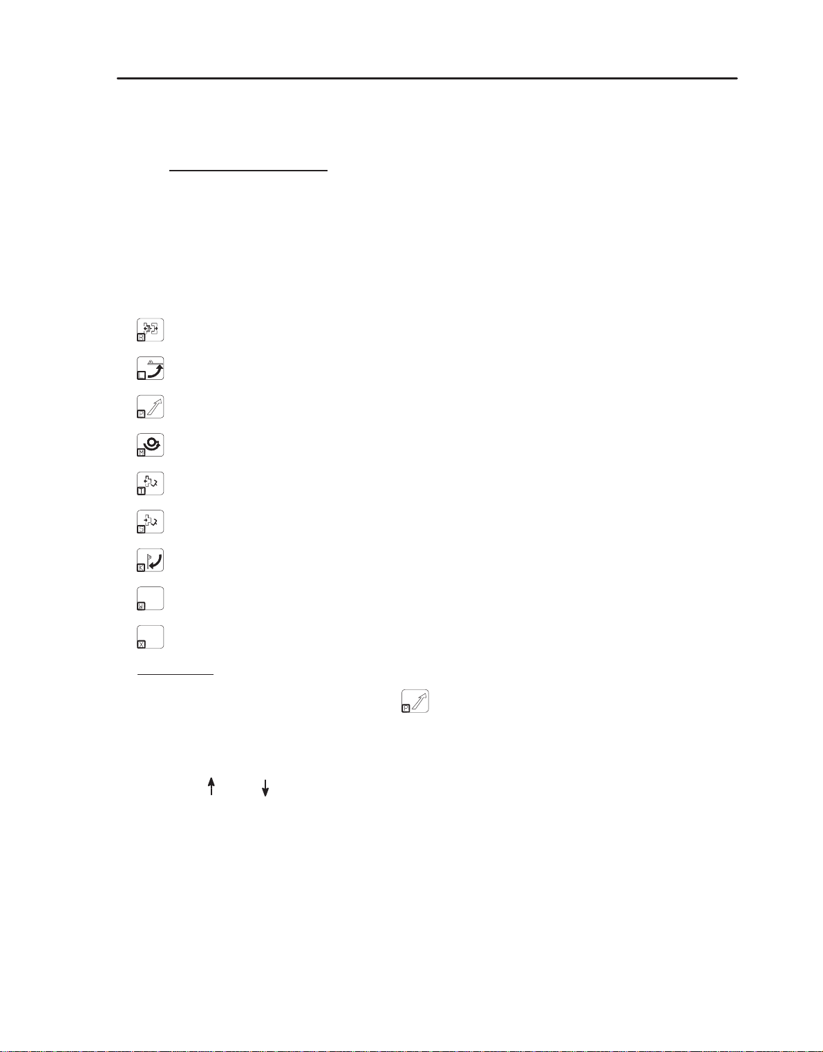
Certain areas are directly accessible from the keyboard :
: beginning of the PRG editing area (0 x 006 430).
: beginning of the PLC editing area (0 x 009 430).
: beginning of the program storage in RAM area (0 x 00B 300).
: beginning of the MODULE where the programs are stored (0 x 800 000).
: transfer buffer PRG E17.
area at which reading is to begin is given in hexadecimal (0 to F) using the numerical
: robot serial number in RAM.
: RAM access password.
: beginning of parameters in RAM.
: beginning of the faults 200 to 204 message table in RAM.
For example
: to access the beginning of the program storage area, the procedure is as follows :
[Memo_M] –> [M_Read] –> [Address] –>
*
The keys
:
[ + ] or [ – ] to change addresses 2 by 2.
[ ]
[PG DN] or [PG UP] to change addresses 100 by 100 (hexadecimal).
or
[ ]
to change addresses 10 by 10 (hexadecimal).
Page 4

I – Memory
* The function keys F1 to F5 :
[Address] to change the address.
[Modif] to change the contents of the memory area displayed (word).
[Search] to search for a particular word (e.g. : FA1B)
System
Configuration
S900II
[Print] to
print the memory contents from the displayed address (in order to search
for the incorrect instructions which will be printed as ????).
[StopPr] to stop sending the memory contents to the printer.
Note
: To access the modification function, a password is necessary which remains valid as long as the
user
does not exit the “M_Read” procedure. Certain critical system areas cannot be read
and all requests
to modify them will be rejected.
By default, the value given after modification request is 0 x FFFF (useful to delete words in the
memory).
As for the other functions, the EXIT key is used to abandon a request or to exit the procedure.
Page 5
System
Configuration
S900II
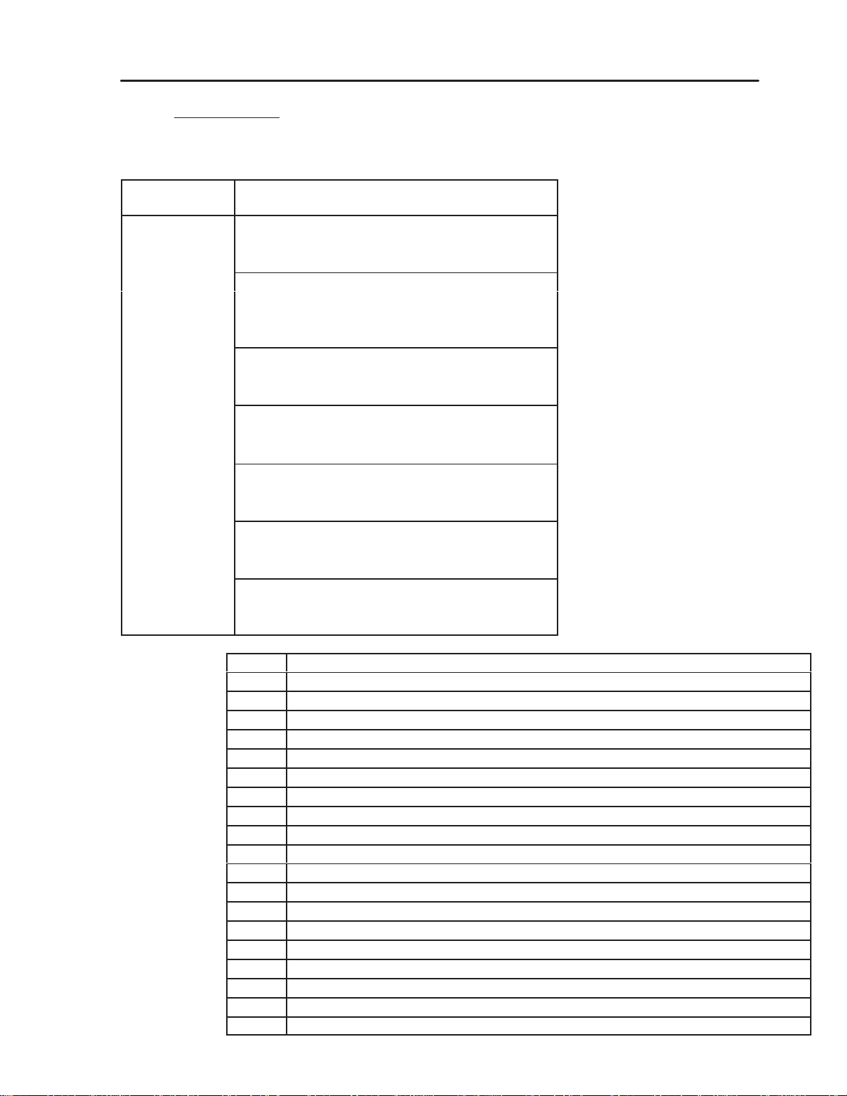
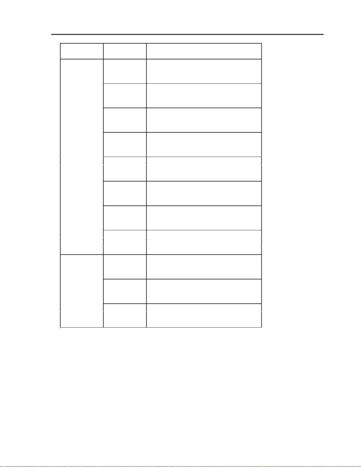
I – 2. Memory areas
I – 2. 1.Data saved in RAM (512 K x 8) 0 to 7 FFFF
ess in
Addr
Hexadecimal
00000
Variables used by Philips (BOOT)
027FF
02800
“Fixed” SEPRO variables, see table below for
details of the variables
0A4FF
0A500
SEPRO parameters in RAM
0B2FF
0B300
PRG storage area (128 K × 8)
2A6FF
2A700
SEPRO variables / work tables
37FFF
38000
Temporary transfer area (128 K x 8)
57FFF
58000
Piles and heaps used by the ERM kernel
7FFFF
Contents
I – Memory
02800 En Ordre = RAM contents correct indicator (GIRLAFRIDOU).
02810 Bit_U_S = System and user bits table.
02890 Bit_Tpo = PLC timer bits table.
028A0 Imag_S = Images of the 255 ON/OFF outputs.
029A0 Imag_E = Image of the 255 ON/OFF inputs.
02AA0 Word_U = User words table (16–bit WORD).
02AE0 Word_S
= System words table (see Programming Level 2 manual for description).
02B20 Tpo_Aut = PLC timers table.
02B40 Compt = Counters table (standard and stacking).
04AA0 Pile_Def = Pile of historic faults.
04BC0 Comptime = Times basic counter.
04BC4 Dir_RAM = PRG / PLC directory in editing area.
04C04 Dir_PP = PRG directory in save area.
05254 Dir_PLC = PLC directory in save area.
05710 Mod_PP = PRG directory in the module.
05D60 Mod_PLC = PLC directory in the module.
0621C Tab_temps = Robot times table.
06230 WWord_U = Double words table (32 bits).
06430 Ram_PP = PRG editing area.
09430 Ram_PLC = PLC editing area.
Page 6
I – Memory
System
Configuration
S900II
I – 2. 2.Program addressing in memory
The PRG and PLC programs are stored in the RAM memory, starting from the address 0xB300.
The maximum length of a PRG is 12286 bytes ; 4096 bytes for a PLC.
This area reserved for the permanent storage varies depending on the option 32 to 128 Kbytes.
that it remains compatible with previous software versions, the RAM if formatted with 0xFFFF like
So
an
EEPROM.
This formatting is carried out when the robot is first started up (for the 128 Kbytes) or
when the memory is totally set to 0 [ RsMEM ] (on the size provided for in the options)
parameters are stored in FLASHPROM at the address
The
0xF10E0000. An image of this address is
stored in RAM at the address 0xA500. The length of the parameters is fixed at 2800 bytes.
“SAP message” file is stored in FLASHPROM at the address 0xF10E1200.
The
Its length is fixed at
4590 bytes.
The programs, parameters and SAP messages are transferred via a temporary buffer of 12286 bytes
at the address 0x38000. (This buffer can be extended to 128 Kbytes).
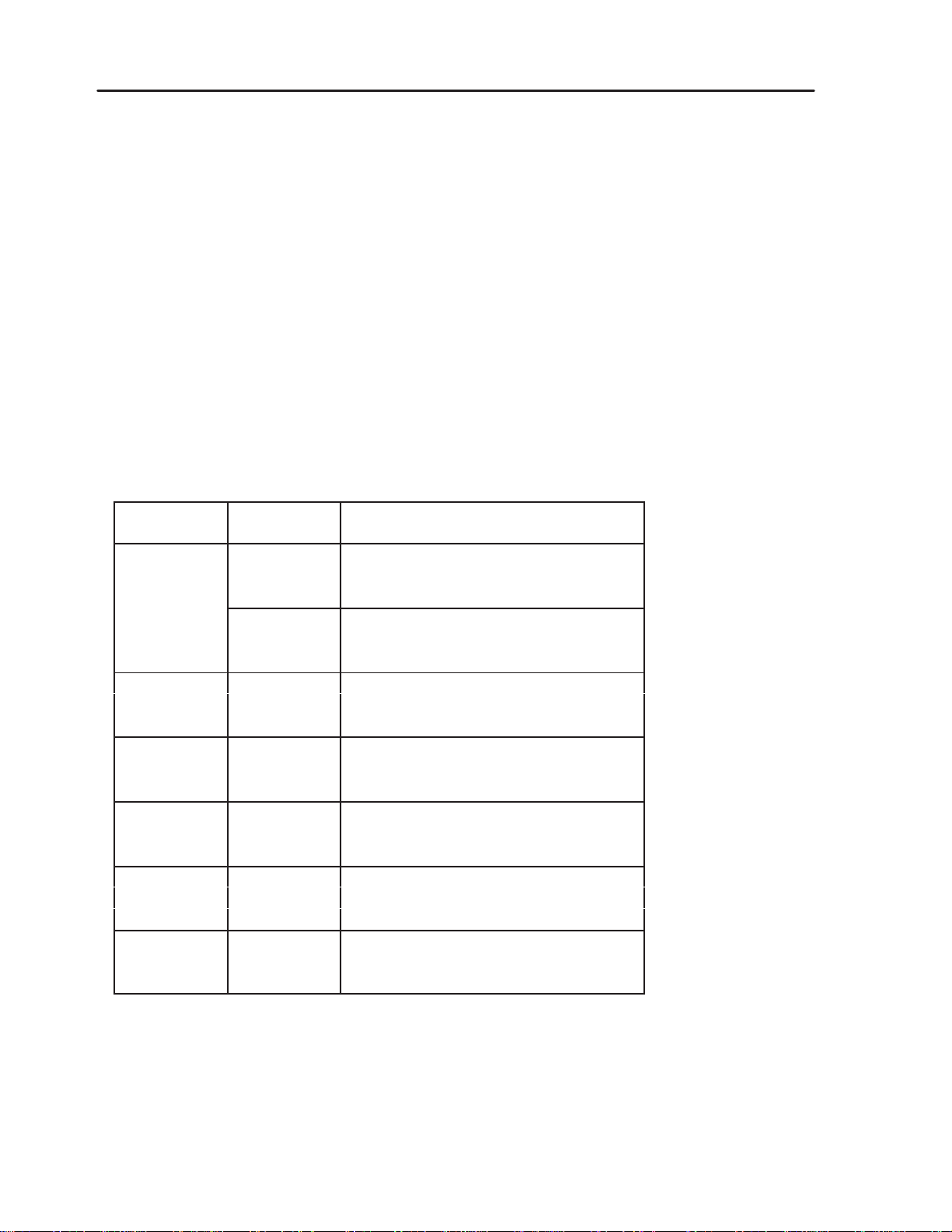
I – 2. 3.Data in Flashprom (1 M x 8) F10 00000 to F10 FFFFF
Block
number
Addr
ess in
Hexadecimal
Contents
F10 00000
ERM kernel + SEPRO program
1st block F10 0FFFF
F10 10000
SEPRO code (1)
F10 1FFFF
F10 20000
2nd block SEPRO code (2)
F10 3FFFF
F10 40000
3rd block SEPRO code (3)
F10 5FFFF
F10 60000
4th block SEPRO code (4)
F10 7FFFF
F10 80000
5th block SEPRO code (5)
F10 9FFFF
F10 A0000
6th block Reserved for extension of SEPRO code
F10 BFFFF
Page 7
System
Configuration
S900II
I – Memory
Block
number
Addr
ess in
Hexadecimal
Contents
F10 C0000
Messages in language 1
F10 CEBEF
F10 CEBF0
Messages in language 2
F10 DD7DF
F10 DD7E0
Font robot 1
F10 DE7EF
F10 DE7F0
Font robot 2
7th block F10 DF7FF
F10 DF800
Messages Code converter table IMM 1
F10 DF9FF
F10 DFA00
Code converter table IMM 2
F10 DFBFF
F10 DFC00
Code converter table Printer 1
F10 DFDFF
F10 DFE00
Code converter table Printer 2
F10 DFFFF
F10 E0000
SEPRO parameters
8th block F10 E0DFF
F10 E1200
Parameters
SAP messages
and SAP F10 E2256
F10 E2400
Reserved for SEPRO
F10 FFFFF
Page 8
I – Memory
System
Configuration
S900II
I – 3. Specific information
These are directly accessed using the Memory Read function followed by the request [Address] and
a letter :
to access the memory area containing the passwords.
–
to access the memory area containing the serial number and the type of robot.
–
15 0
B2A0
B2A2
B2A4
B2A6
B2A8
B2AA
B2AC
B2AE
B2B0
B2B4
B2E0
B2E2
B2E4
B2E6
B2E8
B2EA
B2EC
B2EE
00 00
00 00
00 00
04 D2
00 00
00 00
00 00
00 00
00 00
00 00
000400
00
007335
98
Password to access edition (....)
Password to access parameters (....)
Password to access maintenance (....)
Password to block the modes (....)
Password to block the selection of the PRG N° to be
executed (....)
Operating time.
Operating time in automatic.
Robot serial number :
E.g. 1024
Robot type :
E.g. 350 BB (000) –> 3503000–D –> 357398–H
Model Type Specific
0 BX
1 BY
2 BZ
3 BB
4 BC
5 AX
6 AY
7 AZ
Page 9
System
Configuration
S900II
II – Instruction codes
II – INSTRUCTION
CODES
II – 1. Part programs
Type
Display Codop (hexadecimal) Examples
of Instruction
ACTION ACT 00 (to 99) * A000 [oper. 16 bits] A000000C = ACT12
Action
No.
OUTPUT OUT 000 (to 255) * A001 [oper. 16 bits] A0010050 = OUT080
Output No.
INPUT IN 000 (to 255) A002 [oper. 16 bits] A002000A = IN010
Normal
Input No.
INPUT IN/000 (to 255) A003 [oper. 16 bits] A0030020 = IN/032
Reverse
TIMER TIME 001 to 999
A004[oper.4bits]0[oper.11bits] A004000A = TIME010
Input No.
SAP marker
No.
V
alue
in 1/10s
A004300A = TIME010
Marker P03
TIME W_00 à 15 A004 0000 1 [oper.11bits] A004080A = TIMEW10
A004080F = TIMEW15
Word
No.
BIT BIT 000 (to 127) A005 [oper. 16 bits] A0050063 = BIT 99
Bit No.
/ BIT 000 (to 127) A006 [oper. 16 bits] A006007D = BIT 127
* The actions and outputs replaced by text (e.g.: part grip 1) keep the same CODOP
Page 10
II – Instruction codes
System
Configuration
S900II
Type
Display Codop (hexadecimal) Examples
of Instruction
FUNCTIONS (FUNC)
SPEED VEL.X 001 to 100 B000[oper.4bits][oper.12bits] B0000062 = VEL.X 098
in % of the VEL.Y 001 to 100
parametered speed VEL.Z 001 to 100
VEL.B 001 to 100
VEL.C 001 to 100
B001[oper.4bits][oper.12bits] B001000A = VEL.Y 010
B002[oper.4bits][oper.12bits] B0020012 = VEL.Z 018
B003[oper.4bits][oper.12bits] B0030064 = VEL.B 100
B004[oper.4bits][oper.12bits] B004A032 = VEL.C 050
SAP marker
N°
V
alue in
1/10s
Marker P10
VEL.X WW_*nn B050 0000 [oper.12bits] B0500042 = VEL.X WW066
VEL.Y WW_*nn B051 0000 [oper.12bits] B0510043 = VEL.Y WW067
VEL.Z WW_*nn B052 0000 [oper.12bits] B0520042 = VEL.Z WW066
VEL.B WW_*nn B053 0000 [oper.12bits] B0530042 = VEL.B WW066
VEL.C WW_*nn B054 0000 [oper.12bits] B0540043 = VEL.C WW067
*(nn
= 00 to 55
Word
and 66 to 67)
No.
ACCELERATION ACC.X 001 to 100 B010 [oper. 16 bits] B010000F = ACC.X 015
in % of the parametered ACC.Y 001 to 100 B011 [oper. 16 bits] B0110064 = ACC.Y 100
acceleration ACC.Z 001 to 100 B012 [oper. 16 bits] B0120044 = ACC.Z 068
ACC.B 001 to 100 B013 [oper. 16 bits] B0130005 = ACC.B 005
ACC.C 001 to 100 B014 [oper. 16 bits] B0140032 = ACC.C 050
Value
in %
Master MOVEMENT MASTER.X B030
MASTER.Y B031
MASTER.Z B032
MASTER.B B033
MASTER.C B034
IMPRECISION IMP.X B040
IMP.Y B041
IMP.Z B042
IMP.B B043
IMP.C B044
Page 11

System Configuration
S900II
II – Instruction codes
Type
of Instruction
Display Codop (hexadecimal) Examples
MOTORIZED
MOTIONS
SLOW APPROACH SLA.X 001 to 100 B020 [oper. 16 bits] B0200026 = SLA.X 026
in % of the maximum SLA.Y 001 to 100 B021 [oper. 16 bits] B0210034 = SLA.Y 034
parametered speed SLA.Z 001 to 100 B022 [oper. 16 bits] B0220090 = SLA.Z 090
SLA.B 001 to 100 B023 [oper. 16 bits] B0230100 = SLA.B 100
SLA.C 001 to 100 B024 [oper. 16 bits] B0240010 = SLA.C 010
Value
in %
LINEAR
ABSOLUTE X.ABS_L distance C000[oper.8bits][oper.24bits] C00000000664=X.ABS.L00163.6
(Numerical operands) Y.ABS_L distance C001[oper.8bits][oper.24bits] C001000F423F=Y.ABS.L99999.9
Z.ABS_L distance C002[oper.8bits][oper.24bits] C00200000320=Z.ABS.L00080.0
B.ABS_L distance C003[oper.8bits][oper.24bits] C0030000003F=B.ABS.L00006.3
C.ABS_L distance C004[oper.8bits][oper.24bits] C0040000050C=C.ABS.L00150.0
STACKING X.STK_L distance C010[oper.8bits][oper.24bits] C01000008ACF=X.STK.L03453.5
Y.STK_L distance C011[oper.8bits][oper.24bits] C01100030DE3=Y.STK.L20016.3
Z.STK_L distance C012[oper.8bits][oper.24bits] C01200000159=Z.STK.L00034.5
B.STK_L distance C053 Reserved for general STKs
C.STK_L distance C054 Absolute distances from the header
RELATIVE X.REL_L distance C020[oper.8bits][oper.24bits] C020800000A0=X.REL.L–0016.0
Y.REL_L distance C021[oper.8bits][oper.24bits] C021000000A0=Y.REL.L–0016.0
Z.REL_L distance C022[oper.8bits][oper.24bits] C0228001869F=Z.REL.L–9999.9
B.REL_L distance C023[oper.8bits][oper.24bits] C02300002706=B.REL.L+0999.9
C.REL_L distance C024[oper.8bits][oper.24bits] C0240000000A=C.REL.L+0001.0
CHECKING X.CTL_L distance C030[oper.8bits][oper.24bits] C03000000664=X.CTL.L00163.6
Y.CTL_L distance C031[oper.8bits][oper.24bits] C031000F423F=Y.CTL.L9999.9
Z.CTL_L distance C032[oper.8bits][oper.24bits] C03200000320=Z.CTL.L00080.0
B.CTL_L distance C033[oper.8bits][oper.24bits] C0330000003F=B.CTL.L00006.3
C.CTL_L distance C034[oper.8bits][oper.24bits] C0340500050C=C.CTL.L00150.0
Marker
Distance in 1/10 mmSAP marker No.
P05
ROTATING
ABSOLUTE X.ABS_R Angle C100[oper.8bits][oper.24bits] C10000000664=X.ABS.R00163.6
(Numerical operands) Y.ABS_R Angle C101[oper.8bits][oper.24bits] C101000005DC=Y.ABS.R00150.0
Z.ABS_R Angle C102[oper.8bits][oper.24bits] C10200000320=Z.ABS.R00080.0
B.ABS_R Angle C103[oper.8bits][oper.24bits] C1030000003F=B.ABS.R00006.3
C.ABS_R Angle C104[oper.8bits][oper.24bits] C10400000159=C.ABS.R00034.5
STACKING X.STK_R Angle C110[oper.8bits][oper.24bits] C11000008ACF=X.STK.R03453.5
Y.STK_R Angle C111[oper.8bits][oper.24bits] C11100030DE3=Y.STK.R20016.3
Z.STK_R Angle C112[oper.8bits][oper.24bits] C11200000159=Z.STK.R00034.5
RELATIVE X.REL_R Angle C120[oper.8bits][oper.24bits] C12000000384=X.REL.R+90.0
Y.REL_R Angle C121[oper.8bits][oper.24bits] C12180000320=Y.REL.R–90.0
Z.REL_R Angle C122[oper.8bits][oper.24bits] C12200000320=Z.REL.R+80.0
B.REL_R Angle C123[oper.8bits][oper.24bits] C12380000159=B.REL.R–34.5
C.REL_R Angle C124[oper.8bits][oper.24bits] C1240000003F=C.REL.R+06.3
Page 12

II – Instruction codes
System Configuration
S900II
Type
Display Codop (hexadecimal) Examples
of Instruction
CHECKING X.CTL_R Angle C130[oper.8bits][oper.24bits] C13000000664=X.CTL.R00163.6
Y.CTL_R Angle C131[oper.8bits][oper.24bits] C131000F423F=Y.CTL.R9999.9
Z.CTL_R Angle C132[oper.8bits][oper.24bits] C13200000320=Z.CTL.R00080.0
B.CTL_R Angle C133[oper.8bits][oper.24bits] C1330000003F=B.CTL.R00006.3
C.CTL_R Angle C134[oper.8bits][oper.24bits] C1340000050C=C.CTL.R00150.0
Angle
in
1/10 deg.
C10200AAAAAA=Z.ABS.RTeach
TEACHING Teach C
Previous
instruction
Instruction code
SAP Marker No.
[oper.8bits]AAAAAA C01000AAAAAA=X.STK.LTeach
SAP marker No.
MOTORIZED
MOTIONS (cont’d)
LINEAR
ABSOLUTE X.ABS_L WW *nn C200 [oper. 16 bits] C200000A = X.ABS.L WW10
(Words) Y.ABS_L WW *nn C201 [oper. 16 bits]
Z.ABS_L WW *nn C202 [oper. 16 bits]
B.ABS_L WW *nn C203 [oper. 16 bits]
C.ABS_L WW *nn C204 [oper. 16 bits]
STACKING X.STK_L WW *nn C210 [oper. 16 bits]
C210000B = X.STK.L WW11
Y.STK_L WW *nn C211 [oper. 16 bits]
Z.STK_L WW *nn C212 [oper. 16 bits]
RELATIVE X.REL_L WW *nn C220 [oper. 16 bits]
C2200041 = X.REL.L WW65
Y.REL_L WW *nn C221 [oper. 16 bits]
Z.REL_L WW *nn C222 [oper. 16 bits]
B.REL_L WW *nn C223 [oper. 16 bits]
C.REL_L WW *nn C224 [oper. 16 bits]
CHECKING X.CTL_L WW *nn C230 [oper. 16 bits]
C2300010 = X.CTL.L WW16
Y.CTL_L WW *nn C231 [oper. 16 bits]
Z.CTL_L WW *nn C232 [oper. 16 bits]
B.CTL_L WW *nn C233 [oper. 16 bits]
C.CTL_L WW *nn C234 [oper. 16 bits]
ROTATING
ABSOLUTE X.ABS_R WW *nn C300 [oper. 16 bits] C300000A = X.ABS.R WW10
(Words) Y.ABS_R WW *nn C301 [oper. 16 bits]
Z.ABS_R WW *nn C302 [oper. 16 bits]
B.ABS_R WW *nn C303 [oper. 16 bits]
C.ABS_R WW *nn C304 [oper. 16 bits]
STACKING X.STK_R WW *nn C310 [oper. 16 bits]
C3100020 = X.STK.R WW32
Y.STK_R WW *nn C311 [oper. 16 bits]
Z.STK_R WW *nn C312 [oper. 16 bits]
*(nn
= 00 to 55 and 64 to 65)
Page 13

System
Configuration
S900II
II – Instruction codes
Type
Display Codop (hexadecimal) Examples
of Instruction
RELATIVE X.REL_R WW *nn C320 [oper. 16 bits] C3200001 = X.REL.R WW01
Y.REL_R WW *nn C321 [oper. 16 bits]
Z.REL_R WW *nn C322 [oper. 16 bits]
B.REL_R WW *nn C323 [oper. 16 bits]
C.REL_R WW *nn C324 [oper. 16 bits]
CHECKING X.CTL_R WW *nn C330 [oper. 16 bits]
C3300041 = X.CTL.R WW65
Y.CTL_R WW *nn C331 [oper. 16 bits]
Z.CTL_R WW *nn C332 [oper. 16 bits]
B.CTL_R WW *nn C333 [oper. 16 bits]
C.CTL_R WW *nn C334 [oper. 16 bits]
*(nn
= 00 to 55 and 64 to 65)
WWORD
No.
FREE X. FREE C040
Y. FREE C041
Z. FREE C042
B. FREE C043
C. FREE C044
LINE LIN. B046
Page 14

II – Instruction codes
System Configuration
S900II
Type
Display Codop (hexadecimal) Examples
of Instruction
LINEAR
POS_ANA X = POS ANA + distance C060 [oper. 32 bits]
Y = POS ANA + distance C061 [oper. 32 bits]
Z = POS ANA + distance C062 [oper. 32 bits]
B = POS ANA + distance C063 [oper. 32 bits]
C = POS ANA + distance C064 [oper. 32 bits]
POS_NUM X = POS NUM + distance C070 [oper. 32 bits]
Y = POS NUM + distance C071 [oper. 32 bits]
Z = POS NUM + distance C072 [oper. 32 bits]
B = POS NUM + distance C073 [oper. 32 bits]
C = POS NUM + distance C074 [oper. 32 bits]
VEL ANA NORMAL X = VEL ANA_N + distance C080 [oper. 32 bits]
Y = VEL ANA_N + distance C081 [oper. 32 bits]
Z = VEL ANA_N + distance C082 [oper. 32 bits]
B = VEL ANA_N + distance C083 [oper. 32 bits]
C = VEL ANA_N + distance C084 [oper. 32 bits]
VEL ANA INTEGRAL X = VEL ANA_I + distance C090 [oper. 32 bits]
Y = VEL ANA_I + distance C091 [oper. 32 bits]
Z = VEL ANA_I + distance C092 [oper. 32 bits]
B = VEL ANA_I + distance C093 [oper. 32 bits]
C = VEL ANA_I + distance C094 [oper. 32 bits]
VEL NUM NORMAL X = VEL NUM_N + distance C0A0[oper. 32 bits]
Y = VEL NUM_N + distance C0A1 [oper. 32 bits]
Z = VEL NUM_N + distance C0A2 [oper. 32 bits]
B = VEL NUM_N + distance C0A3 [oper. 32 bits]
C = VEL NUM_N + distance C0A4 [oper. 32 bits]
VEL NUM INTEGRAL X = VEL NUM_I + distance C0B0[oper. 32 bits]
Y = VEL NUM_I + distance C0B1 [oper. 32 bits]
Z = VEL NUM_I + distance C0B2 [oper. 32 bits]
B = VEL NUM_I + distance C0B3 [oper. 32 bits]
C = VEL NUM_I + distance C0B4 [oper. 32 bits]
Page 15

System
Configuration
S900II
II – Instruction codes
Type
Display Codop (hexadecimal) Examples
of Instruction
ROTATING
POS_ANA X = POS ANA + angle C160 [oper. 32 bits]
Y = POS ANA + angle C161 [oper. 32 bits]
Z = POS ANA + angle C162 [oper. 32 bits]
B = POS ANA + angle C163 [oper. 32 bits]
C = POS ANA + angle C164 [oper. 32 bits]
POS_NUM X = POS NUM + angle C170 [oper. 32 bits]
Y = POS NUM + angle C171 [oper. 32 bits]
Z = POS NUM + angle C172 [oper. 32 bits]
B = POS NUM + angle C173 [oper. 32 bits]
C = POS NUM + angle C174 [oper. 32 bits]
VEL ANA NORMAL X = VEL ANA_N + angle C180 [oper. 32 bits]
Y = VEL ANA_N + angle C181 [oper. 32 bits]
Z = VEL ANA_N + angle C182 [oper. 32 bits]
B = VEL ANA_N + angle C183 [oper. 32 bits]
C = VEL ANA_N + angle C184 [oper. 32 bits]
VEL ANA INTEGRAL X = VEL ANA_I + angle C190 [oper. 32 bits]
Y = VEL ANA_I + angle C191 [oper. 32 bits]
Z = VEL ANA_I + angle C192 [oper. 32 bits]
B = VEL ANA_I + angle C193 [oper. 32 bits]
C = VEL ANA_I + angle C194 [oper. 32 bits]
VEL NUM NORMAL X = VEL NUM_N + angle C1A0[oper. 32 bits]
Y = VEL NUM_N + angle C1A1 [oper. 32 bits]
Z = VEL NUM_N + angle C1A2 [oper. 32 bits]
B = VEL NUM_N + angle C1A3 [oper. 32 bits]
C = VEL NUM_N + angle C1A4 [oper. 32 bits]
VEL NUM INTEGRAL X = VEL NUM_I + angle C1B0[oper. 32 bits]
Y = VEL NUM_I + angle C1B1 [oper. 32 bits]
Z = VEL NUM_I + angle C1B2 [oper. 32 bits]
B = VEL NUM_I + angle C1B3 [oper. 32 bits]
C = VEL NUM_I + angle C1B4 [oper. 32 bits]
Page 16

II – Instruction codes
System
Configuration
S900II
Type
Display Codop (hexadecimal) Examples
of Instruction
TEST, CONDITIONS
. 1 Operand
on Bit IF BIT 000 (to 127) D000 [oper. 16 bits]
IF/BIT 000 (to 127) D010 [oper. 16 bits]
on Output IF OUT 000 (to 255) D001 [oper. 16 bits]
IF/OUT 000 (to 255) D011 [oper. 16 bits]
on Input IF IN/000 (to 255) D002 [oper. 16 bits]
IF IN 000 (to 255) D003 [oper. 16 bits]
IF/IN 000 (to 255) D013 [oper. 16 bits]
on Timer IF TIM 00 (to 15) D004 [oper. 16 bits]
IF/TIM 00 (to 15) D014 [oper. 16 bits]
Operand
No.
. 2 Operands
* on Word (16 bits) IF WRD 000 (to 4095) D300 [oper. 16 bits]
–> 1st Operand IF/WRD 000 (to 4095) D310 [oper. 16 bits]
with decimal value = 0000 (to 9999) D400 [oper. 16 bits]
> = 0000 (to 9999) D401 [oper. 16 bits]
< = 0000 (to 9999) D402 [oper. 16 bits]
AND 0000 (to 9999) D403 [oper. 16 bits]
with hexadecimal value = 0000 (to FFFF) D410 [oper. 16 bits]
> = 0000 (to FFFF) D411 [oper. 16 bits]
< = 0000 (to FFFF) D412 [oper. 16 bits]
AND 0000 (to FFFF) D413 [oper. 16 bits]
Note : If the decimal
value cannot exceed
9,999, the hexadecimal
value
goes up to
65,535.
with Counter = CNT 00 (to 15) D420 [oper. 16 bits]
> = CNT 00 (to 15) D421 [oper. 16 bits]
< =CNT 00 (to 15) D422 [oper. 16 bits]
AND CNT 00 (to 15) D423 [oper. 16 bits]
with Inputs (modulo 16) =IN 000 (to 112) D430 [oper. 16 bits]
> =IN 000 (to 112) D431 [oper. 16 bits]
< =IN 000 (to 112) D432 [oper. 16 bits]
AND IN 000 (to 112) D433 [oper. 16 bits]
with Word (16 bits) = WRD 0000 (to 4095) D440 [oper. 16 bits]
> = WRD 0000 (to 4095) D441 [oper. 16 bits]
< = WRD 0000 (to 4095) D442 [oper. 16 bits]
AND WRD 0000(to 4095) D443 [oper. 16 bits]
Page 17

System
Configuration
S900II
II – Instruction codes
Type
Display Codop (hexadecimal) Examples
of Instruction
* on WWord (32 bits) IF WWRD 000 (to 127) D320 [oper. 16 bits]
–> 1st Operand IF/WWRD 000 (to 127) D330 [oper. 16 bits]
with decimal value =
> =
< =
AND
with hexadecimal value =
> =
< =
AND
00000000
00000000 (to FFFFFFFF)
(to 09999999)
00000000
00000000
00000000
00000000
00000000
00000000
(to 09999999)
(to 09999999)
(to 09999999)
(to FFFFFFFF)
(to FFFFFFFF)
(to FFFFFFFF)
D500 [oper. 32 bits]
D501 [oper. 32 bits]
D502 [oper. 32 bits]
D503 [oper. 32 bits]
D510 [oper. 32 bits]
D511 [oper. 32 bits]
D512 [oper. 32 bits]
D513 [oper. 32 bits]
with Counter = CNT 00 (to 15) D520 [oper. 16 bits]
> = CNT 00 (to 15) D521 [oper. 16 bits]
< = CNT 00 (to 15) D522 [oper. 16 bits]
AND CNT 00 (to 15) D523 [oper. 16 bits]
with Inputs (modulo 16) = IN 000 (to 112) D530 [oper. 16 bits]
> = IN 000 (to 112) D531 [oper. 16 bits]
< = IN 000 (to 112) D532 [oper. 16 bits]
AND IN 000 (to 112) D533 [oper. 16 bits]
Note
: If the decimal
value cannot exceed
9,999,999,
the
hexadeci
mal value goes up to
4,294,967,295.
-
with Word (16 bits) = WRD 0000 (to 4095) D540 [oper. 16 bits]
> = WRD 0000 (to 4095) D541 [oper. 16 bits]
< = WRD 0000 (to 4095) D542 [oper. 16 bits]
AND WRD 0000(to 4095) D543 [oper. 16 bits]
with WWord (32 bits) = WWRD 000 (to 127) D550 [oper. 16 bits]
> = WWRD 000 (to 127) D551 [oper. 16 bits]
< = WWRD 000 (to 127) D552 [oper. 16 bits]
AND WWRD 000(to 127) D553 [oper. 16 bits]
* on Counter IF CNT 00 (to 15) D340 [oper. 16 bits]
–> 1st Operand IF/CNT 00 (to 15) D350 [oper. 16 bits]
with decimal value = 0000 (to 9999) D900 [oper. 16 bits]
> = 0000 (to 9999) D901 [oper. 16 bits]
< = 0000 (to 9999) D902 [oper. 16 bits]
AND 0000 (to 9999) D903 [oper. 16 bits]
with hexadecimal value =
0000 (to FFFF) D910 [oper. 16 bits]
> = 0000 (to FFFF) D911 [oper. 16 bits]
< = 0000 (to FFFF) D912 [oper. 16 bits]
AND 0000 (to FFFF) D913 [oper. 16 bits]
with Counter = CNT 00 (to 15) D920 [oper. 16 bits]
> = CNT 00 (to 15) D921 [oper. 16 bits]
< = CNT 00 (to 15) D922 [oper. 16 bits]
AND CNT 00 (to 15) D923 [oper. 16 bits]
Page 18

II – Instruction codes
System
Configuration
S900II
Type
Display Codop (hexadecimal) Examples
of Instruction
with Inputs (modulo 16) = IN 000 (to 112) D930 [oper. 16 bits]
> = IN 000 (to 112) D931 [oper. 16 bits]
< = IN 000 (to 112) D932 [oper. 16 bits]
AND IN 000 (to 112) D933 [oper. 16 bits]
with Word (16 bits) = WRD 0000 (to 4095) D940 [oper. 16 bits]
> = WRD 0000 (to 4095) D941 [oper. 16 bits]
< = WRD 0000 (to 4095) D942 [oper. 16 bits]
AND WRD 0000(to 4095) D943 [oper. 16 bits]
INITIALIZATION
. 1 Operand
* on Bit –> 1 SET.BIT 032 (to 127) D015 [oper. 16 bits]
on Bit –> 0 RST.BIT 032 (to 127) D017 [oper. 16 bits]
* on Output –> 1 SET.OUT 000 (to 127) D016 [oper. 16 bits]
on Output –> 0 RST.OUT 000 (to 127) D018 [oper. 16 bits]
* on Word –> 0 RST.WRD 0000 (to 4095) D019 [oper. 16 bits]
V
ariable number
* on WWord –> 0 RST.WWRD 00 (to 63) D01D [oper. 16 bits]
Variable
number
* on Counter –> 0 RST.CNT 0000 (to 0015) D01A 00 [oper. 8 bits]
Counter number
RST.CNT 0041 (to 9980)
D01A[oper. 8 bits] [oper. 8 bits]
PRG No.
SP No.
. 2 Operands
* on Word (16 bits) SET.WRD 0000 (to 4095) D600 [oper. 16 bits]
–> 1st Operand
with decimal value = 0000 (to 9999) D700 [oper. 16 bits]
+ 0000 (to 9999) D701 [oper. 16 bits]
– 0000 (to 9999) D702 [oper. 16 bits]
x 0000 (to 9999) D703 [oper. 16 bits]
/ 0000 (to 9999) D704 [oper. 16 bits]
AND 0000 (to 9999) D705 [oper. 16 bits]
OR 0000 (to 9999) D706 [oper. 16 bits]
with hexadecimal value = 0000 (to FFFF) D710 [oper. 16 bits]
+ 0000 (to FFFF) D711 [oper. 16 bits]
– 0000 (to FFFF) D712 [oper. 16 bits]
x 0000 (to FFFF) D713 [oper. 16 bits]
/ 0000 (to FFFF) D714 [oper. 16 bits]
AND 0000 (to FFFF) D715 [oper. 16 bits]
OR 0000 (to FFFF) D716 [oper. 16 bits]
Page 19

System Configuration
S900II
II – Instruction codes
Type
Display Codop (hexadecimal) Examples
of Instruction
with Counter = CNT 00 (to 15) D720 [oper. 16 bits]
+ CNT 00 (to 15) D721 [oper. 16 bits]
– CNT 00 (to 15) D722 [oper. 16 bits]
x CNT 00 (to 15) D723 [oper. 16 bits]
/ CNT00 (to 15) D724 [oper. 16 bits]
AND CNT 00 (to 15) D725 [oper. 16 bits]
OR CNT 00 (to 15) D726 [oper. 16 bits]
with Inputs (modulo 16) = IN 000 (to 112) D730 [oper. 16 bits]
+ IN 000 (to 112) D731 [oper. 16 bits]
– IN 000 (to 112) D732 [oper. 16 bits]
x IN 000 (to 112) D733 [oper. 16 bits]
/ IN 000 (to 112) D734 [oper. 16 bits]
AND IN 000 (to 112) D735 [oper. 16 bits]
OR IN 000 (to 112) D736 [oper. 16 bits]
with Word (16 bits) = WRD 0000 (to 4095) D740 [oper. 16 bits]
+ WRD 0000 (to 4095) D741 [oper. 16 bits]
– WRD 0000 (to 4095) D742 [oper. 16 bits]
x WRD 0000 (to 4095) D743 [oper. 16 bits]
/ WRD 0000 (to 4095) D744 [oper. 16 bits]
AND WRD 0000 (to 4095)D745 [oper. 16 bits]
OR WRD 0000 (to 4095) D746 [oper. 16 bits]
* on WWord (32 bits) SET.WWRD 000 (to 127) D620 [oper. 16 bits]
–> 1st Operand
with decimal value =
with hexadecimal value =
with Counter = CNT 00 (to 15
00000000
00000000
+
–
00000000
x
00000000
/
00000000
AND
OR
00000000
+
00000000
00000000
–
x
00000000
/
00000000
AND
OR
+ CNT 00 (to 15
– CNT 00 (to 15
x CNT 00 (to 15
/ CNT 00 (to 15
(to 09999999)
(to 09999999)
(to 09999999)
(to 09999999)
(to 09999999)
00000000
00000000
(to FFFFFFFF)
(to FFFFFFFF)
(to FFFFFFFF)
(to FFFFFFFF)
(to FFFFFFFF)
00000000
00000000
(to 09999999)
(to 09999999)
(to FFFFFFFF)
(to FFFFFFFF)
) D820 [oper. 16 bits]
) D821 [oper. 16 bits]
) D822 [oper. 16 bits]
) D823 [oper. 16 bits]
) D824 [oper. 16 bits]
AND CNT 00 (to 15
OR CNT 00 (to 15
) D826 [oper. 16 bits]
D800 [oper. 32 bits]
D801 [oper. 32 bits]
D802 [oper. 32 bits]
D803 [oper. 32 bits]
D804 [oper. 32 bits]
D805 [oper. 32 bits]
D806 [oper. 32 bits]
D810 [oper. 32 bits]
D811 [oper. 32 bits]
D812 [oper. 32 bits]
D813 [oper. 32 bits]
D814 [oper. 32 bits]
D815 [oper. 32 bits]
D816 [oper. 32 bits]
) D825 [oper. 16 bits]
Page 20

II – Instruction codes
System
Configuration
S900II
Type
Display Codop (hexadecimal) Examples
of Instruction
with Inputs (modulo 16) = IN *nn D830 [oper. 16 bits]
+ IN *nn D831 [oper. 16 bits]
– IN *nn D832 [oper. 16 bits]
*nn = 00 to 112 x IN *nn D833 [oper. 16 bits]
and 136 to 240 / IN *nn D834 [oper. 16 bits]
AND IN *nn D835 [oper. 16 bits]
OR IN *nn D836 [oper. 16 bits]
with Word (16 bits) = WRD 0000 (to 4095) D840 [oper. 16 bits]
+ WRD 0000 (to 4095) D841 [oper. 16 bits]
– WRD 0000 (to 4095) D842 [oper. 16 bits]
x WRD 0000 (to 4095) D843 [oper. 16 bits]
/ WRD 0000 (to 4095) D844 [oper. 16 bits]
AND WRD 0000 (to 4095) D845 [oper. 16 bits]
OR WRD 0000 (to 4095) D846 [oper. 16 bits]
with WWord (32 bits) =
WWRD *nn and 200–202 D850 [oper. 16 bits]
+ WWRD *nn D851 [oper. 16 bits]
– WWRD *nn D852 [oper. 16 bits]
*nn = 0 to 127 x WWRD *nn D853 [oper. 16 bits]
/ WWRD *nn D854 [oper. 16 bits]
AND WWRD*nn D855 [oper. 16 bits]
OR WWRD *nn D856 [oper. 16 bits]
* on Counter SET.CNT 0000 (to 0015) D640 [oper. 8 bits] Standard counter
–> 1st Operand SET.CNT 0041 (to 9980)
D640[oper. 8 bits] [oper. 8 bits] Stacking counter
PRG
No.
SP No.
with decimal value = 0000 (to 9999) DA00 [oper. 16 bits]
+ 0000 (to 9999) DA01 [oper. 16 bits]
– 0000 (to 9999) DA02 [oper. 16 bits]
x 0000 (to 9999) DA03 [oper. 16 bits]
/ 0000 (to 9999) DA04 [oper. 16 bits]
AND 0000 (to 9999) DA05 [oper. 16 bits]
OR 0000 (to 9999) DA06 [oper. 16 bits]
with hexadecimal value =
0000 (to FFFF) DA10 [oper. 16 bits]
+ 0000 (to FFFF) DA11 [oper. 16 bits]
– 0000 (to FFFF) DA12 [oper. 16 bits]
x 0000 (to FFFF) DA13 [oper. 16 bits]
/ 0000 (to FFFF) DA14 [oper. 16 bits]
AND 0000 (to FFFF) DA15 [oper. 16 bits]
OR 0000 (to FFFF) DA16 [oper. 16 bits]
with Counter = CNT 00 (to 15) D920 [oper. 16 bits]
+ CNT 00 (to 15) D921 [oper. 16 bits]
– CNT 00 (to 15) D922 [oper. 16 bits]
x CNT 00 (to 15) D922 [oper. 16 bits]
/ CNT 00 (to 15) D922 [oper. 16 bits]
AND CNT 00 (to 15) D923 [oper. 16 bits]
OR CNT 00 (to 15) D923 [oper. 16 bits]
Page 21

System Configuration
S900II
II – Instruction codes
Type
Display Codop (hexadecimal) Examples
of Instruction
with Inputs (modulo 16) = IN 000 (to 112) DA30 [oper. 16 bits]
+ IN 000 (to 112) DA31 [oper. 16 bits]
– IN 000 (to 112) DA32 [oper. 16 bits]
x IN 000 (to 112) DA33 [oper. 16 bits]
/ IN 000 (to 112) DA34 [oper. 16 bits]
AND IN 000 (to 112) DA35 [oper. 16 bits]
OR IN 000 (to 112) DA36 [oper. 16 bits]
with Word (16 bits) = WRD 0000 (to 4095) DA40 [oper. 16 bits]
+ WRD 0000 (to 4095) DA41 [oper. 16 bits]
– WRD0000 (to 4095) DA42 [oper. 16 bits]
x WRD 0000 (to 4095) DA43 [oper. 16 bits]
/ WRD 0000 (to 4095) DA44 [oper. 16 bits]
AND WRD 0000 (to 4095)DA45 [oper. 16 bits]
OR WRD 0000 (to 4095) DA46 [oper. 16 bits]
–> + 1 INC.CNT 0000 (to 0015) D01B 00 [oper. 8 bits]
Standard No.
INC.CNT 0041 (to 9980)
D01B[oper. 8 bits] [oper. 8 bits]
PRG
No.
SP No.
–> – 1 DEC.CNT 0000 (to 0015) D01C 00 [oper. 8 bits]
Standard No.
DEC.CNT 0041 (to 9980)
D01C[oper. 8 bits] [oper. 8 bits]
PRG No.
SP No.
Page 22

II – Instruction codes
II – 2. PLC programs
System Configuration
S900II
Type
Display Codop (hexadecimal)
of Instruction
PROG.PLC xx header (num) PLC xx FC [oper. 16 bits]
PLC
No.
TEST CONDITION IF ... See part programs
INITIALISATION SET ... See part programs
RST ...
INC ...
DEC ...
COMPARISON xxxx > = xxxx
CMP 0000 (to 0015) V
0000 (to 0015)
AL 0000 (to FFFF)
D020 [oper. 16 bits] [oper. 16 bits]
Counter No.
Value
TIMER xx VALUE xxxx TIMER 00 (to 15) VAL 0000 (to 9999) D021 [oper. 16 bits] [oper. 16 bits]
Timer No.
Pre–selection No.
AND FUNCTION on BIT AND BIT 000 (to 127) D022 [oper. 16 bits]
AND FUNCTION on OUTPUT AND OUT 000 (to 127) D023 [oper. 16 bits]
AND FUNCTION on BIT OR BIT 000 (to 127) D024 [oper. 16 bits]
OR FUNCTION on OUTPUT OR OUT 000 (to 127) D025 [oper. 16 bits]
Variables
No.
END OF PROGRAM END F5 [oper. 16 bits]
PLC No.
Page 23

System Configuration
S900II
III – Pr
ogram codes
III – PROGRAM
III – 1.
Declaration of programs, subroutines and PLCs
"
Header codes of PRG, SP,..., SR, PLC
G F9b xn = Main program
G b = 0, standard PRG (encoded on 15 bits)
b = 1 , SAP PRG (encoded on 15 bits)
G FAnn = STD, STK.. // subroutine (see stacking header)
G FBnn = Return subroutine (see home return header)
G FCnn = PLC program
G FEnn = FREE
"
STEP TRANSITION codes
G EC00 + Step number 0 to 999
G E.g. : EC12 => Step number 18 (decimal)
G E.g. : ED00 => Step number 256 (decimal)
CODES
"
END of PRG, SP..., SR, PLC codes
G F0nn = End of ”standard” SP nn.
G F1nn = End of ”standard” stacking SP nn.
G F2nn = End of ”general” stacking SP nn.
G F3nn = End of SP // nn.
G F4nn = End of simple or total SR nn.
G F8nn = End of simple or total SR with return to step 0 of PRG 00.
G F5nn = End of PLC nn.
G F7nn = End of main program (PRG) nn.
"
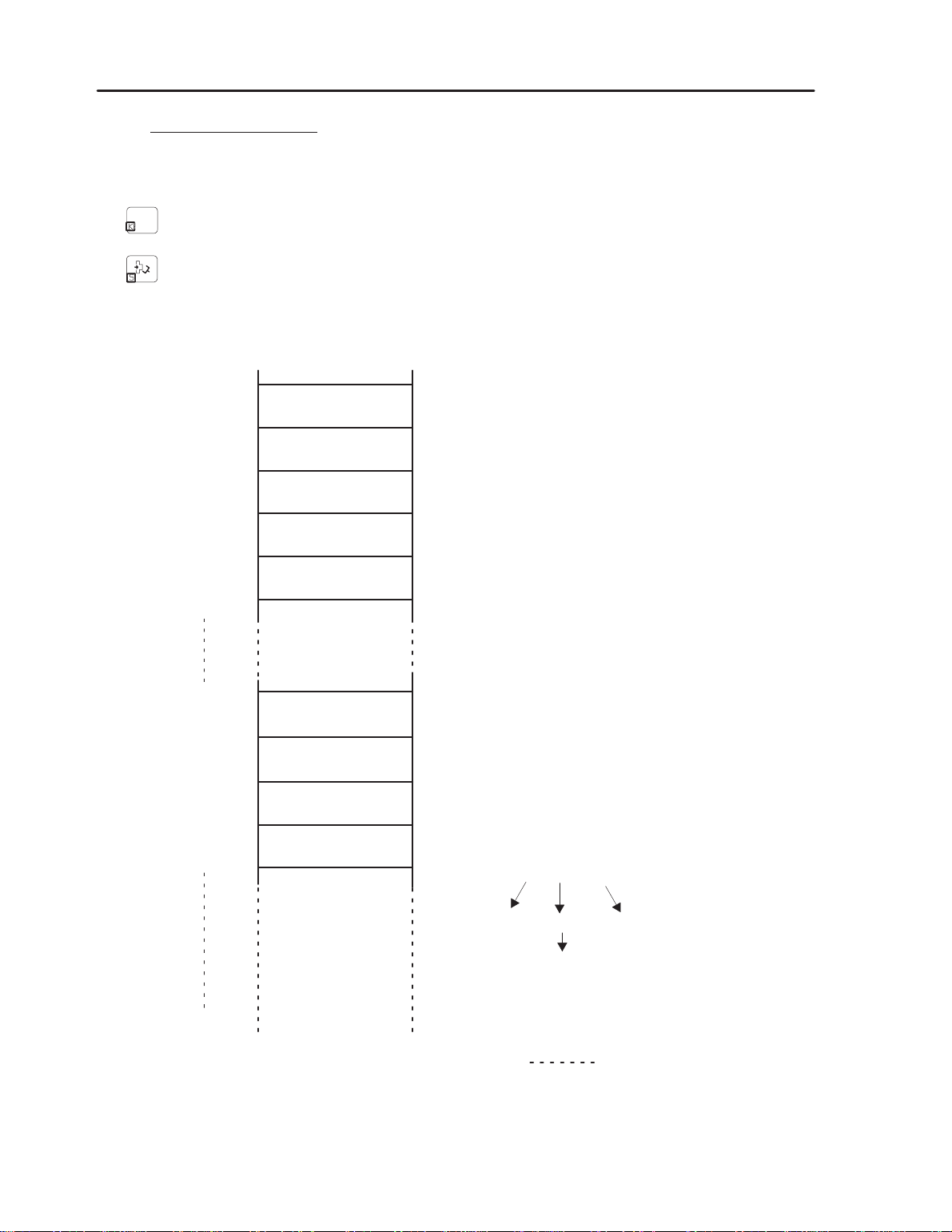
PRG architecture in the memory area
pr
evious pr
ogram
F9 nn
PRG (text)
F7 nn
FA xx
SP
PRG nn
F1 xx
FB pp
F4 pp
F9 mm
SR
following PRG
Page 24

III – Pr
ogram codes
System
Configuration
S900II
III – 2.
Subroutine and program calls
"
SPECIFIC codes for SP, SR, PLC as an instruction
G E000 [oper. 16 bits] :
Standard SP SP nn Lmm (nn = 01 to 40) (mm = 00 to 99)
Regular Stacking SP SP nn D Lmm (or I Lmm) (nn = 41 to 60) (mm = 00 to 99)
General Stacking SP SP nn D Lmm (or I Lmm) (nn = 61 to 80) (mm = 00 to 99)
Parallel SP SP nn L00 (nn = 81 to 99)
The operand contains :
. high order word –> the LABEL number
–> bit 0 x 8000 at 0 indicates DIRECT
–> bit 0 x 8000 at 1 indicates REVERSE
. low order word –> the SP number.
E.g. : E000 0103 –> SP 03 L01
E.g. : E000 8229 –> SP 41 I L02
G E100 [oper. 16 bits] : PLC prog. – Display : PLC 00 (to 99)
G E500 [oper. 16 bits] : Home Return – Display : SR 01 (to 99)
"
Return label
G E600 [oper. 16 bits] : Labels ”L” for SP – Display : L00 to L99
G E700 [oper. 16 bits] : Labels ”R” for SR – Display : R00 to R99
Page 25

System
Configuration
S900II
IV – V
ariable addr
essing
IV – V
ARIABLE
IV – 1. Output – OUT –
Accessible in read and write.
Number
(logical address)
OUT 000
OUT 255
IV – 2. Input – IN –
Accessible in read.
ADDRESSING
Physical
address
28A0
299F
Structures / Functions
2 A1D
Forcing
(Extended monitor)
not used
Continuous status
(See Param. No 14)
OUT
125
Number
(logical address)
IN 000
Physical
address
29A0
2 9AB
IN 255
2A9F
IV – 3. User and system bits – BIT –
Each address corresponds to an 8 bit structure in memory.
not used
0281x
Forcing
(Extended monitor)
x = bit number in hexadecimal (e.g.: Bit 31, address = 0282F).
Only the low order word is used.
– System bits accessible in Read – No. 0 to 30.
Structures / Functions
not used
BIT 0
IN
01
1
– System bits accessible in Read and Write – No. 31 to 33.
– User bits accessible in Read and Write – No. 34 to 127.
For the definition of these bits, see the Programming Level 2 manual, paragraph I3.
Page 26

IV – V
ariable addr
essing
IV – 4. 16 bits user and system words – WRD –
System
Configuration
S900II
Number
(logical address)
WRD 0000 2AA0
WRD 0031 2ADF
WRD 0032 2AE0
WRD 0063 2B1E
WRD 0064 2B20
WRD 0079 2B3F
WRD 0080 2B40
WRD 0095 2B5F
WRD 0096 2B60
WRD 4096 3A9F
Physical
address
Structures / Functions
32 user Words (read/write) with no predefined functions.
B15 0
16 bit structure available
32 system Words (read only). For the definition of these
words, see the Programming Level 2 manual, paragraph
I4
16 user Words (read/write) supporting the PLC timers
(TIM 00 to TIM 15).
16 user Words (read/write) supporting the standard
counters (CNT 00 to CNT 15).
4000 user Words (read/write) supporting the stacking
subroutine counters (CNT 0041 to CNT 9980).
IV – 5. 32 bit user and system words – WWRD –
Number
(logical address)
WWRD 000 6230
WWRD 063 6327
WWRD 064 6328
Physical
address
Structures / Functions
64 user Words (read/write) with no predefined functions.
b31 0
32 bit structure available
64 system Words (read only). For the definition of these
words, see the Programming Level 2 manual, paragraph
I5
WWRD 127 642C
Specific words
WWRD 0116 6400 Values for calculating the automatic anticipated restart.
WWRD 0117 6404 Values for calculating the automatic anticipated restart.
See chapter VI – page 28.
Page 27

System
Configuration
S900II
IV – 6. Counters
Each address corresponds to a 16 bit structure in the memory.
WRD0088
b15 b0
2 B4x
CNT0008
. values from 0000 to 9999 in decimal
. values from 0000 to FFFF in hexadecimal
x = bit number in hexadecimal (e.g.: CNT 0008, address = 2 B50).
– Standard counters – No. 0000 to 0015 (0x2B40 to 0x2B5E).
– Regular stacking counters – No. 0041 to 9960 (as from 0x2 B60).
– General stacking counters – No 0061 to 9980.
IV – V
ariable addr
essing
For the definition of these counters, see the Programming Level 2 manual, paragraph I6.
IV – 7. Timers
IV – 7. 1.End of timer for part program
Accessible in read and write.
Number
(logical address)
Physical
address
Structures / Functions
TIM00 2 890
TIM01 2 891
TIM02 2 892
TIM03 2 893
TIM04 2 894
TIM05 2 895
TIM06 2 896
2 897
TIM07 2 897
TIM08 2 898
not used
TIM09 2 899
TIM10 2 89A
Only the low order word is used
TIM11 2 89B
TIM12 2 89C
TIM13 2 89D
TIM14 2 89E
TIM15 2 89F
TIM07
IV – 7. 2.PLC timer
TIM00 to 15 = WRD 0064 to 0079 see chapter IV – 4.
Accessible in read and write.
Page 28

V – CPU fault signalling
System
Configuration
S900II
V – CPU FAUL
V – 1. Flashing
These signal a CAN network fault by displaying the problem number in binary on the LEDs at the
bottom of the CPU, and the node number (if concerned) on the LEDs at the top if the pendant is not
functioning.
30
Leds
T SIGNALLING
1 = CAN driver initialization fault
2 = Write problem in Flashprom
5 = A double (or more) node on the network (code + node)
6 = Problem during the CONNECTION phase (code + node)
7 = Problem during the PREPARATION phase (code + node)
8 = Problem during the START phase (code + node)
= The network does not correspond to the parametered configuration (code + node)
9
10 = “Node–guarding” problem (code + node). Communication fault with the pendant ;
this
may be due to the CAN speed being too great for the length of the cable used,
line adaptation, or interference, etc.
11 = CPU emission problem
12 = CPU reception problem
13 = Topology fault of the remote I/O
15
= EMERGENCY message received (code + node). Problem on the pendant or with
communication between the pendant and the CPU (see 10)
or a bad
Note : In the event of a NODE GUARDING fault, fault 15 may appear alternately with fault 10.
Page 29

System
Configuration
S900II
V – CPU fault signalling
V – 2. Fixed
Leds
These signal a fault when powering up by giving the problem number in binary on the LEDs at the
bottom of the CPU, and the node number (if concerned) on the LEDs at the top if the pendant is not
functioning.
1 = Problem with recovering the parameters in Flashprom
2 = Problem during the opening of the PC link
3 = Problem during the opening of the EUROMAP 17 link
4 = Problem during the opening of the printer 2 link
5 = Problem during the opening of the CAN link
6 = Message not present in Flashprom
7 = Problem with the CPU’
8 = Problem with the Flashprom’
s RAM
s checksum
9 = Problem with the axes declared and the axes’ boards present
10 = The configuration has changed
11 = Problem during the initialization of the axes’ boards by the CPU
15
= Communication problem with the
pendant during powering up. The CAN speed
may be changed by transfering the parameters with the PC at 2400 Bds, slave = 1.
Page 30

VI – IMM Anticipated Restart
System Configuration
S900II
VI – IMM
"
ANTICIPATED REST
Parameter 174 : type of IMM anticipated restart
ART
G 0 : no anticipated restart
G 1 : anticipated restart
G 2 : programmed delay anticipated restart –> WWRD 63 programmed in step 0.
"
Parameter
175 : basic value of the auto–adaptative delay and
the programmed delay
"
Parameter 176 : minimum value of the auto–adaptative delay (safety margin)
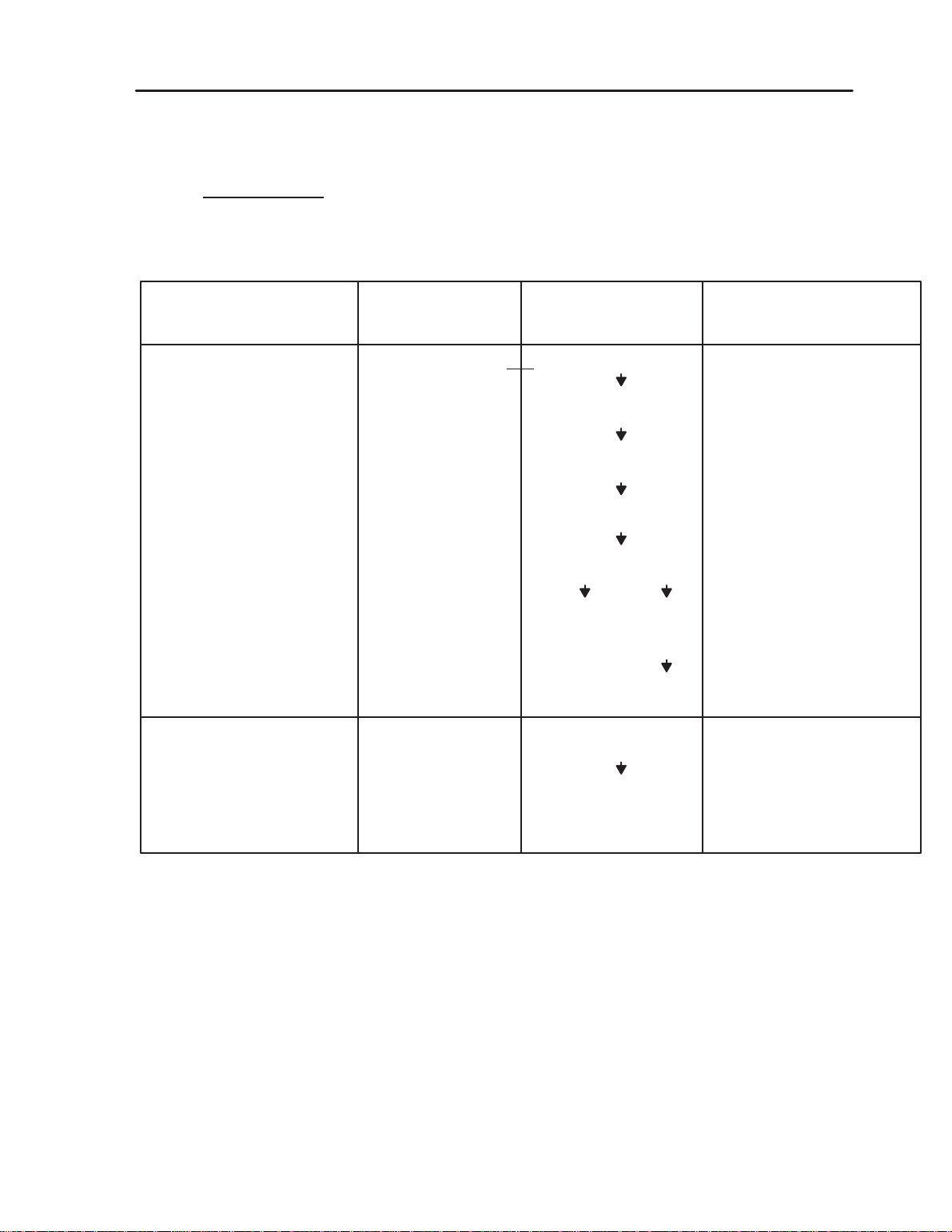
Anticipated restart effective if :
G offset wait is not valid (parameter 451)
G and if the robot is in automatic
G and if Kv equals 100 %
G and if there is a SET WWRD63 in step 0 of the program
G and if the value of WWRD63 is greater than or equal to
VCM
programmed
VCM
Tr = WWRD 116
double the minimum value of
in
the case of
restart with
parameter 175
2
programmed
delay
BHM
P176
Tm = WWRD 117
MO
Tr = robot disengaging time in 1/10 s (WWRD 116)
Tm = IMM motion start time in 1/10 s (WWRD 117)
Rt = theoretical delay = Tr – Tm + P176 or 0 if the result is negative
Rapp = Applied delay
Rapp > Rt
yes
no
Rapp = Rt
Rapp = 66% of (Rt – Rapp)
There is a fault if mould open (or OPA) goes to 0 and BHM = 0
D_5
: MOVEMENT OUTSIDE CAMS
D_32:
PREMATURE MACHINE RESTART
(if there is no anticipated restart running)
(if there is an anticipated restart running)
Page 31

System
Configuration
S900II
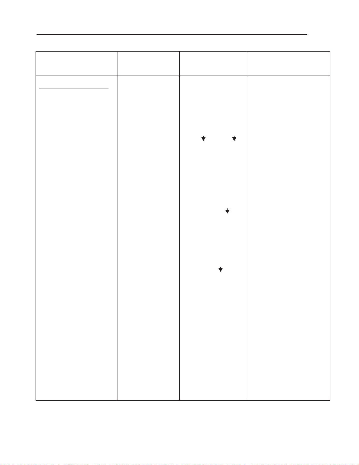
Safety circuit principle.
VI – IMM Anticipated Restart
A hard–wired circuit controls the respective positions of the moving mould (“MO” = Mould Open
signal) and of the robot (“ZBD” = Arm Free Area / “ZHM” = Outside Mould Area signal).
output of this
The
hard–wired circuit (”MO” + ”ZBD” + ”ZHM” = ”KA301”) activates a power relay
(KA301 contactor).
During normal operation, the KA301 relay is activated. The KA301 contacts are used in series with
the SBD relay contact from the interface board, which therefore means that the software safety that
manages the SBD relay with a hard–wired safety device is doubled.
When
there
is a fault (robot position not conform compared to the moving mould position), the KA301
relay falls, which
in turn activates the control relay KA16A, which is self–powered and which stops
the KA301 relay becoming active (the blocking of KA301 prohibits the IMM cycle).
You must power down the robot cabinet to cancel this fault.
FOR 32 OUTPUT BOARDS : as OUTxx active at power up
ANCILLARY “ARM
FREE” SAFETY
“KA301” relay
CONTROL
ANCILLARY “ARM
FREE” SAFETY
“KA301” relay
CONTROL
Page 32

VI – IMM Anticipated Restart
System
Configuration
S900II
IF IN XX
SET WORD 62 = 200
Until a parameter for the control input for the anticipated restart safety circuit is integrated into the
software, this input must be monitored and a fault must be generated using the monitoring PLC.
RELANCE ANTICIPEE NON CONFORME : in French
ANTICIPATED RESTART NOT CONFORM : in English
REARME ANTICIPADO NO CONFORME : in Spanish
VORAUSB. NEUSTART FEHLERHAFT : in German
 Loading...