

Page 1

CONAIR
MNL-00102
WARNING - Reliance on this Manual Could Result in Severe Bodily Injury or Death!
This manual is out-of-date and is provided only for its technical information, data and capacities. Portions of this manual
detailing procedures or precautions in the operation, inspection, maintenance and repair of the product forming the subject
matter of this manual may be inadequate, inaccurate, and/or incomplete and cannot be used, followed, or relied upon.
Contact Conair at info@conairgroup.com or 1-800-654-6661 for more current information, warnings, and materials about
more recent product manuals containing warnings, information, precautions, and procedures that may be more adequate
than those contained in this out-of-date manual.
MANUAL
CL-79
05-15-96 79 1
Page 2

CONAIR
Contents
1. Introduction.....................................................................................................3
2. Technical specifications ............................................................................ 4
2.1 Dimensions ......................................................................................................... 4
2.2 Data ....................................................................................................................4
3. Functional description ............................................................................ 5-6
3.1 Overview.............................................................................................................5
3.2 Safety system..................................................................................................... 6
4. Safety regulations ...................................................................................... 7
4.1 Overview ............................................................................................................. 7
4.2 Sound level ......................................................................................................... 7
5. Installation ................................................................................................ 8-9
5.1 Pre-start checks .................................................................................................. 8
5.2 Opening and closing the hopper and screenbox ................................................ 8
5.3 Electrical connection........................................................................................... 9
6. Operation and daily maintenance..........................................................10-11
6.1 Starting and stopping........................................................................................ 10
6.2 Inspection ......................................................................................................... 10
6.3 Cleaning............................................................................................................ 11
6.4 Trouble-shooting............................................................................................... 11
7. Servicing ................................................................................................. 12-17
7.1 Changing the knives ....................................................................................12-13
7.2 Sharpening the knives .................................................................................14-15
7.3 Inspecting and adjusting the belts .................................................................... 16
7.4 Lubrication ........................................................................................................ 1 6
7.5 Assembling/disassembling the rotor pulley.......................................................17
8. Spare parts list .................................................................................... 18-26
8.1 Overview........................................................................................................... 18
8.2 Ordering spare parts......................................................................................... 18
8.1.1 79, Cutter housing, all models.............................................................................. 19
8.1.1 79, Cutter housing,all models .......................................................................... 20-21
8.1.2 79, table ................................................................................................................ 22
8.1.2 79, diagram ........................................................................................................... 22
8.1.3 79, table ................................................................................................................ 23
8.1.3 79,diagram ............................................................................................................ 23
8.1.4 79, Hopper ............................................................................................................ 24
8.1.5 79, Blower F3 with cyclone AX-5.......................................................................... 25
8.1.6 Pause/pulse relay when emptying with air veyor ................................................. 26
9. Electrical scheme......................................................................................... 27
10. Layout .................................................................................................... 28-31
10.1 Dimensions ..................................................................................................28-31
11. Options .................................................................................................... 32-35
11.1 Overview ........................................................................................................... 32
11.1.1 79, all models: Third fixed knife, disassembling/assembling ............................. 33
11.1.2 79, all models: Third fixed knife, sharpening...................................................... 34
05-15-96 79 2
Page 3

1. Introduction
This manual is for CONAIR MAR TIN's 79 series granulators. The
abbreviations mean:
-B = Band conveyor -U = Suction blower
-L = Low level -V = Ejector (Air V eyor).
The manual should be studied carefully before installing and using the
equipment, in order to prevent personal injury and damage to the machinery .
Always take great care when the knives are within reach,
since they are very sharp and can cause personal injury.
CONAIR MAR TIN granulators are built for granulation of injection moulded,
blow moulded or extruded plastic waste where the granulator’s size and
performance corresponds to the type of waste. For any other products or
materials, approval must be obtained from the dealer or head-office in order for
the conditions of the guarantee to remain valid.
CONAIR
The different types of granulator are designed so that maintenance and cleaning
can be carried out quickly and simply , both during routine maintenance as well
as when changing colour or material.
All servicing work should be carried out by a person with technical training or
corresponding professional experience. The manual contains instructions for
both handling and servicing the granulator . Chapter 7, which contains servicing
instructions, is intended for service engineers. Other chapters contain
instructions for the daily operator .
Delivered with the granulator are a manual, tool kit and touch-up paint.
Any modifications, changes, or rebuilding of the granulator must be approved
by CONAIR MAR TIN in order to avoid personal injury and damage to
machinery and to ensure that the documentation remains correct.
If you have any questions, please contact your local dealer or our head-office.
05-15-96 79 3
Page 4

CONAIR
2. Technical specifications
2.1 Dimensions
See chapter 10, Layout.
2.2 Data
Serial Number
Motor power......................................................................
Capacity ......................................................................
V-belts ......................................................................
Voltage ......................................................................
Blower type (optional) .......................................................
Rotating knives .................................................................
Fixed knives ......................................................................
Screen ......................................................................
Weight:.............................................................................. -L= 185 kg
.................................................................................. -LB = 220 kg
.................................................................................. -LBU = 250 kg
.................................................................................. -LBV= 240 kg
05-15-96 79 4
Page 5
CONAIR
3. Functional description
3.1 Overview
79 granulators are designed for grinding different types of plastic waste.
79
79
C
B
A
E
D
A
D
B
C
E
The granulator is controlled from an electrical cabinet with a start/stop function
and an emergency stop button.
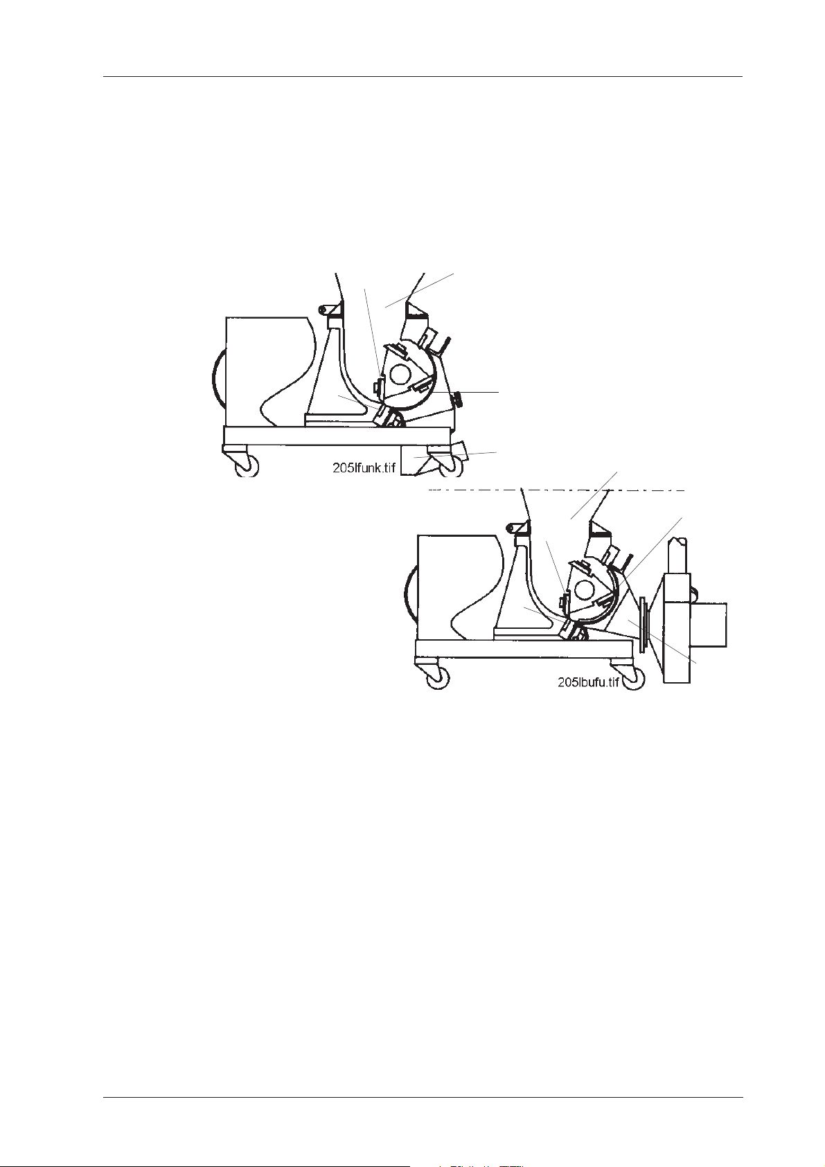
The material is fed into the hopper (A) and falls down to the rotor. The rotor’s
knives (B) grind the material against the fixed knives (C) in the cutter housing.
Both the fixed and rotating knives can be changed or re-sharpened when
necessary . The sharpening is carried out in a special fixture outside of the
granulator .
Under the rotor is a screen (D) through which the granulate passes before it
comes down into the granule bin. The screen is available with various hole sizes
depending on the required degree of coarseness of the granulate.
The granulated material is then collected in the granule bin (E). The standard -L
model is fitted with a suction pipe. The -LBU is fitted with a suction blower
which sucks the granulate out of the granule bin. The -LBV is fitted with an
ejector (air veyor).
The granule bin, screen and screen box are designed to be removed so that the
rotor can easily be cleaned. The hopper is constructed so that it can be opened
up to allow improved access for cleaning and maintenance.
05-15-96 79 5
Page 6

CONAIR
3.2 Safety system
Since there are rotating knives inside the granulator, there is a built-in safety
system to prevent personal injury .
Emergency stop: The equipment is fitted with an emergency stop switch on the
electrical cabinet. The emergency stop is activated by pushing the button. It is
reset by turning the button in the direction of the arrow (anti-clockwise).
Safety switches: The safety system includes 2 safety switches. The switches are
located as follows:
• 1 by the hopper
• 1 by the screenbox
The system is designed so that you have to unscrew the break screw by the
screenbox to be able to open it. The break screw actuates the safety switch,
which cuts off the power so that the rotor stops before the screenbox can be
opened.
The hopper must be lowered and locked before the granulator can be operated.
The safety switch has been installed so that it is not possible to start the
granulator when the hopper is open.
05-15-96 79 6
Page 7

CONAIR
4. Safety regulations
4.1 Overview
The granulator is equipped with safety switches to prevent the front door and
the hopper from being opened during operation.
The following safety measures should always be observed when handling the
granulator:
• Always switch off the power supply using the main circuit-breaker (on
top of the electrical cabinet) before opening the granulator.
• Never put any part of your body into any openings on the granulator
unless the main circuit-breaker is in the "OFF" (=0) position.
• Always be careful when the knives are in reach since they are very
sharp. When the rotor has to be rotated manually, this must be done
with the greatest care!
• Be careful when the hopper and screenbox are opened and closed so
that no part of your body gets caught.
• The granulator cannot be started until the doors and the hopper are
locked.
4.2 Sound level
• Equivalent continuous A-weighted acoustic pressure level 79 = 83.6 dBA
Value measured 1 m from the surface of the machine and 1.6 m above the
surface of the floor during grinding of 5 litres of PE bottles (polyethylene).
05-15-96 79 7
Page 8
CONAIR
5. Installation
All instructions must be carried out in the order described, to prevent personal
injury or damage to machinery .
Always take great care when handling the knives since they ar e
very sharp and can cause personal injury.
The granulator should be connected to the mains supply by an
authorised electrician.
5.1 Pre-start checks
• Before the granulator is installed, the rust preventive should be carefully
cleaned from the parts which are not painted or rustproof.
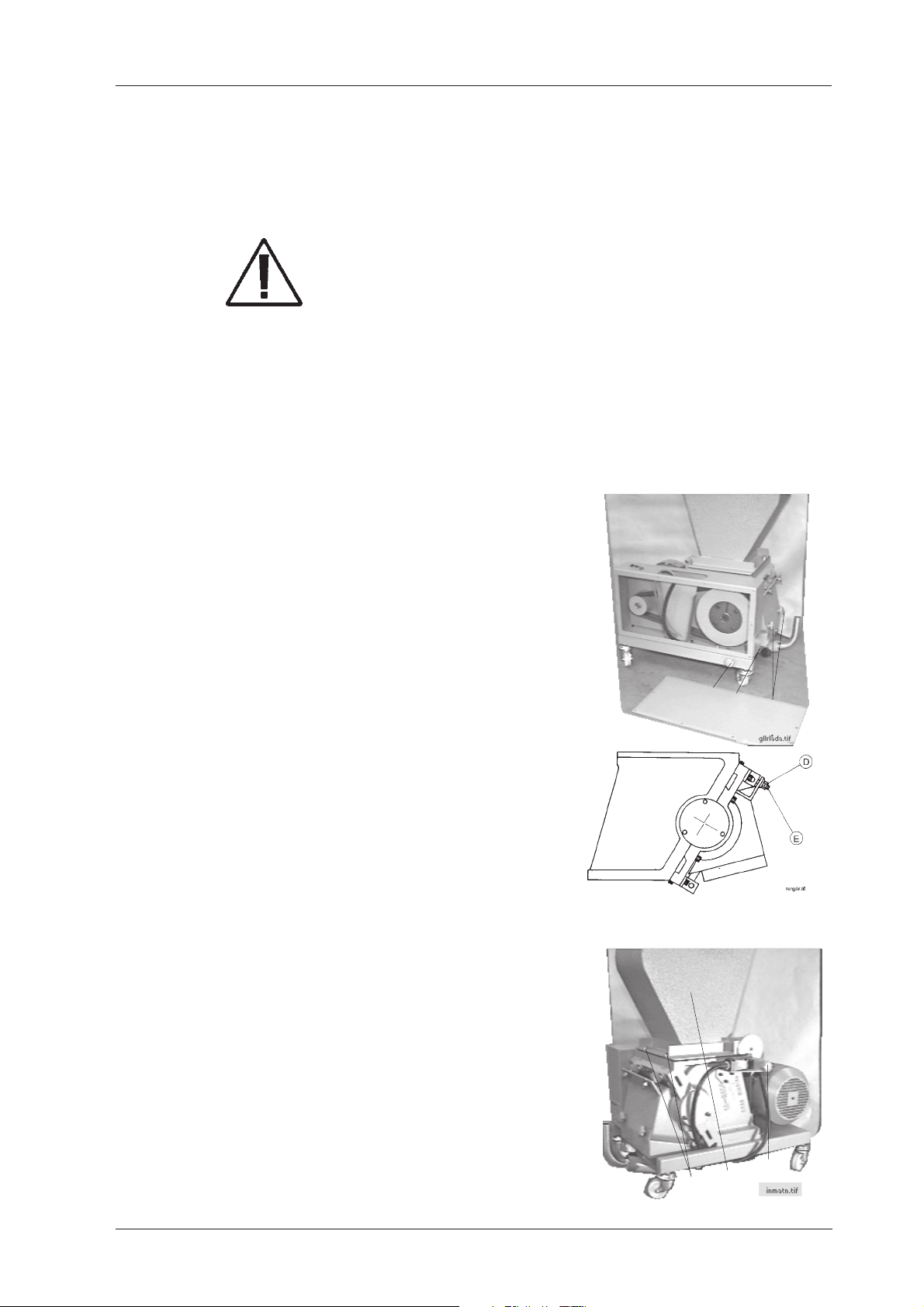
5.2 Opening and closing the hopper and screenbox
Screenbox:
1. Unscrew the star knob (A) and pull out the
granule bin (B).
2. Unscrew the breakscrew (C) until the door's
stop plate is released. A safety switch is then
activated, which cuts off the current to
prevent the machine from being started when
the screenbox is open.
3. Loosen the nuts (D).
4. Raise the link screws (E).
5. Lower the screenbox and lift out the screen.
NOTE: When mounting the screenbox the link
screws' nuts (D) must be tightened quite
hard to avoid only one of the link screws
taking the whole load. Tighten them quite
hard so that the break screw turns easily.
Hopper:
C
B
A
1. Unscrew the break screw (F) on the
right side of the hopper.
2. Loosen the nuts (G).
3. Raise the hopper (I).
F
I
G
05-15-96 79 8
Page 9

CONAIR
5.3 Electrical connection
The granulator should be connected up by an authorised electrician.
• Connect the granulator to the mains supply. See Electrical scheme, chapter
9, connecting (Q1).
Check the granulator motor’s rotation direction as follows:
• Set the main circuit-breaker on the control box to position (1) = “On”.
• Check that the emergency stop switch is not activated. It can be reset by
turning the knob in the direction of the arrow (anti-clockwise).
• Check that the break screws to the
screenbox's and hopper's safety switches
are completely tightened.
• Press in the “START” push-button.
• Check that the granulator motor’s
rotation direction is consistent with the
arrow on the hood.
If a blower is connected, check that its
rotation direction is consistent with the
arrow on the blower hood.
If the rotation direction is not correct:
• Change the incoming phases.
05-15-96 79 9
Page 10
CONAIR
6. Operation and daily maintenance
6.1 Starting and stopping
The start and stop functions are controlled by a change-over button on the
electrical cabinet.
NOTE: The granulator should not be stopped until it has finished grinding all
the material in the hopper and cutter housing. Any remaining material can slow
down the rotor when it is re-started which can overload the motor and trigger
the overload protector. (See 6.4)
6.2 Inspection
There should not be any material in the granulator when the inspection is to be
carried out.
6.2.1 Daily inspection
• Flaps in the hopper. Check that the flaps are not damaged. Damaged parts
should be replaced immediately to prevent bits of the flaps from falling into
the cutter housing and damaging the knives. There is also a risk that
damaged flaps can be thrown back by the machine.
• Emergency stop. Check the emergency stop function by starting the
granulator and then stopping it using the emergency stop button. The
emergency stop is reset by turning the emergency stop button in the
direction of the arrow. The machine can then be re-started by pressing
“START”.
6.2.2 Weekly inspection
• Cables. Inspect all cabling in the machine to see that there is no wear or
other damage. For reasons of personal
protection, damaged parts should be replaced
immediately.
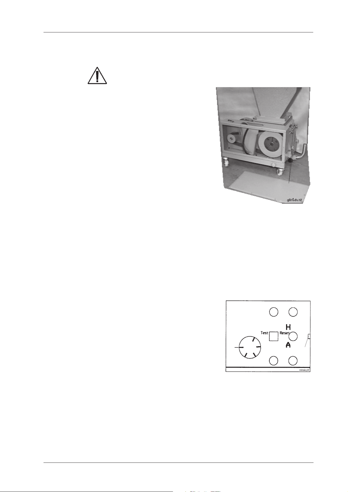
• Safety switches. There are two safety
switches, one for the screen box and one for
the hopper:
Screenbox: Check the safety switch by starting
the granulator and then unscrewing the break
screw (A) on the bottom of the belt guard, as
described in chapter 5.2. The granulator should
have stopped before you are able to open the
screenbox.
A
Hopper: Open the hopper as described in chapter 5.2, but close and lock the
screenbox. Check the safety switch to the hopper by starting the granulator . It
should not be possible to start the granulator until the hopper is lowered and the
break screws are screwed in.
05-15-96 79 10
Page 11
CONAIR
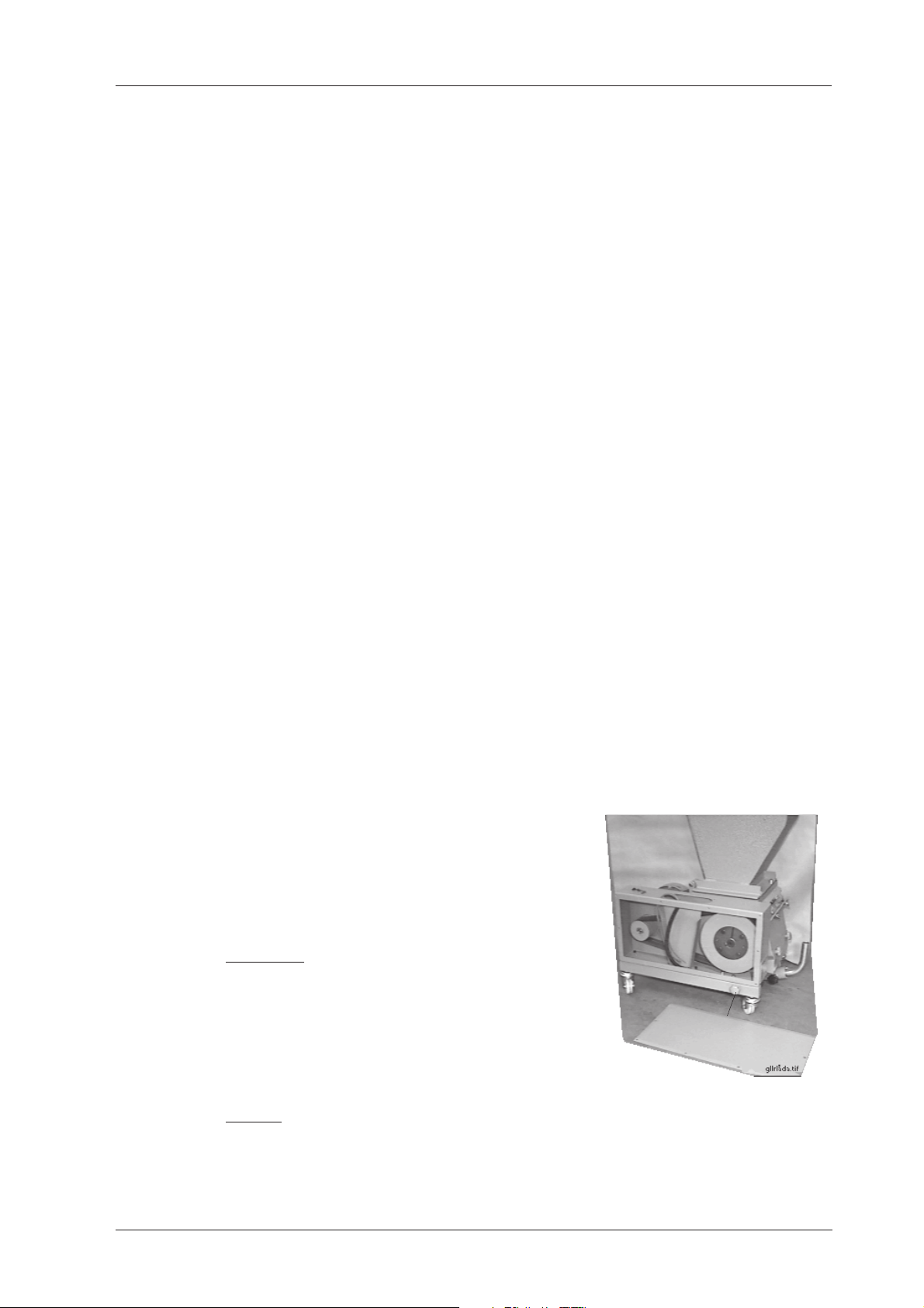
6.3 Cleaning
Always take great care when handling the knives since they ar e
very sharp and can cause personal injury.
1. Open the hopper and screenbox as
described in chapter 5.2.
2. Clean the hopper, flaps, screen and
screenbox and granule bin.
3. Clean the cutter-housing and inside the
stand.
4. Replace all parts in reverse order.
NOTE: When mounting the screenbox the
link screws' nuts (A) must be tightened quite
hard to avoid only one of the link screws
taking the whole load.
A
Note: Steps 2 - 4 should be carried out every time the machine is cleaned,
or at least once every 300 hours.
6.4 T rouble-shooting
6.4.1 If the granulator does not start
• Check that the saftey switches’ break screws are turned fully clockwise. It is
not possible to start the granulator unless the break screws are screwed in.
• Check that the emergency stop is not activated. It can be reset by turning the
button in the direction of the arrow.
• The bimetal relay F1 in the electrical cabinet,
according to the diagram opposite, is
released if you press stop or overload the
granulator. This is indicated by the small
green rectangular pin (P), which sticks up
above the surface of the bimetal relay. When
you reset by pressing the "Reset" button, the
pin (P) is pushed back in so that it is level
with the surface of the bimetal relay.
P
NOTE: Set the main circuit-breaker to position "0" when cleaning the
granulator. Empty the granulator of all material before restarting it.
05-15-96 79 11
Page 12
7. Servicing
All servicing work should be carried out by a qualified service engineer and in
the order described, to prevent personal injury or damage to machinery .
7.1 Changing the knives
When changing the knives, also check for any wear to the screen. For safety
reasons, this should be replaced when the holes in the screen become dropshaped.
Always take great care when handling the knives since they are
very sharp and can cause personal injury. Use protective gloves!
7.1.1 Changing the fixed and rotating knives
For safety reasons, damaged screws must be replaced.
• Open the screenbox as described in chapter 5.2.
Disassembling the rotating knives (C):
CONAIR
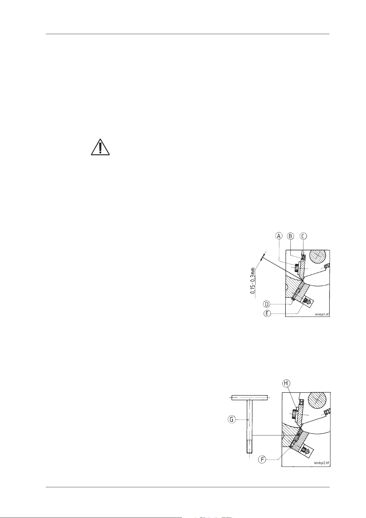
1. Remove the fastening screws (A) and washers (H).
Disassembling the fixed knives:
1. Loosen screws (E), 5 on each long side and 2
on the short side opposite the belt guard, total
12 pieces.
2. Remove the screws (D), 2 on each fixed knife.
3. Loosen the stop screws (F), 2 on each fixed
knife.
4. Screw the special extractor (G) (in the tool kit)
into the threaded hole on the knife end and pull
out the knife.
Assembling the lower fixed knife:
1. Check that the knives and the grooves for the knives are free from plastic
waste, grease, etc.
2. Place the lower fixed knife in position.
3. Adjust the lower fixed knife to its
forward position using the adjusting
screws (F). NOTE: These screws should
only support the rear edge of the knife
and should not be tightened so much that
the knife bends.
4. Tighten the 5 screws (E) (in the diagram
above) along the lower long side with a
torque of 20 Nm.
5. Screw in and tighten the screws (D).
05-15-96 79 12
Page 13

CONAIR
Assembling the rotating knives
1. Clean the cutter's knife location and place a rotating knife in the knife
location.
2. Fasten the screws (A) together with the washers (H) and tighten gently.
3. Adjust the knife using the setting
screws (B) to give the correct
amount of play, 0.15-0.30 mm
between the fixed and rotating
knives. Check using the feeler
gauge included in the tool kit.
4. When the correct amount of play
has been obtained, tighten the
screws (A) with a torque of 200
Nm.
5. Tighten the counter nut.
6. Re-check the amount of play.
Assembling the upper fixed knife
7. Push the upper fixed knife into its
groove.
8. Turn the cutter so that the rotating
knife's cutting edge comes exactly
in front of the upper fixed knife's
cutting edge.
9. Adjust the fixed knife using the
setting screws (D) and (F). By
tightening screws (F) the knife is
moved towards the cutter's centre.
By tightening screws (D) the knife
is moved away from the cutter's
centre.
10.Tighten the 5 screws (E) along the
upper long side, and the two that were loosened on one short side.
11.Check that screws (D) and (F) by the upper fixed knife are not loose.
However, they should not be tightened too much.
12.Rotate the rotor and replace the other rotating knives according to steps 1 5 above.
13.Using a feeler gauge, check that the distance between the fixed and rotating
knives is correct. The distance should not be less than 0.15 mm.
Granulator fitted with a third fixed knife:
See instructions in chapter 11.
05-15-96 79 13
Page 14

CONAIR
7.2 Sharpening the knives
Always take great care when sharpening the knives since they
are very sharp and can cause personal injury.
7.2.1 Overview
NOTE: Use the services of a skilled person when re-sharpening the knives
and only sharpen the edges marked with the special sign! (see diagram
under 7.2.2 and 7.2.3)
The knives must be sharpened so that the correct grinding angles are obtained,
otherwise the granulator will not operate effectively with lightly cutting knives.
During sharpening, the knife must be cooled the whole time with plenty of
water and must definitely not burn or start blueing on the edge since this means
that the knife lacks durability and stability . If this occurs, the knife cannot be
repaired by further grinding down or grinding away of the blued or burnt
colour. The tempered knife may have deep deformations with possible cracking
as a consequence.
The following instructions apply only if you are using CONAIR MARTIN's
sharpening fixture 79. The sharpening fixture is intended for use in a surface
grinding machine and should be fixed on a magnetic board.
7.2.2 Sharpening the fixed and rotating knives
Fixed knives:
Regarding the third fixed knife, see chapter 11.
NOTE: Only the surfaces marked with the special sign should be sharpened.
The specified measurements apply when sharpening the knives.
• The fixed knives are fastened as shown
in the adjacent figure, left part, and the
cutting angle is sharpened at 200.
• The knives can be sharpened only as much as is
shown in the adjacent figure. After that, they are
worn out and should be replaced by new ones in
order for the granulation to be effective.
05-15-96 79 14
Page 15

CONAIR
Rotating knives:
NOTE: All rotating knives should be sharpened equally so that the cutter does
not become unbalanced.
• The rotating knife is fastened
with the stirrup (A) under the
lower part of the knife, as shown
in the adjacent figure, right part.
Ball washers should be used
when tightening. In this position
the relief angle is sharpened.
• Loosen the screws and remove
the stirrup (A), fasten the knife
again. In this position the cutting
angle is sharpened.
• The knives can be sharpened only as
much as is shown in the adjacent
figure. After that, they are worn out
and should be replaced by new ones
in order for the granulation to be
effective.
05-15-96 79 15
Page 16

CONAIR
7.3 Inspecting and adjusting the belts
The V-belts must be inspected after 30 hours’ operation.
• Loosen and remove the outer plate
on the belt guard.
• Load one of the V-belts between the
rotor pulley and the motor pulley
with 25 N in the middle of and at a
right angle to the belt. Measure the
deflection and adjust the distance
between the pulleys as necessary until the tension is correct. The V-belt
should stretch 6 mm.
Adjusting:
• Tension the belt by screwing on the flange nuts (A).
F = 25 N
l = 6 mm
A
7.4 Lubrication
The bearing is delivered filled with grease. The bearing is maintenance-free and
needs no further lubrication.
05-15-96 79 16
Page 17

CONAIR
7.5 Rotor pulley , assembling/disassembling
7.5.1 Rotor pulley
Disassembling
1. Loosen all screws a few turns.
2. Unscrew two of the screws.
3. Lubricate both screws and screw them into the disassembling holes (A).
4. Tighten both disassembling screws alternately until the flange bushing comes
loose from the hub and the unit sits freely on the axle.
5. Lift the whole unit from the axle.
Assembling
1. Clean and degrease the contact surfaces carefully.
2. Place the "flange bushing" in the hub so that the bolt holes line up with each
other.
3. Lubricate the screws. Mount all screws without tightening them completely.
4. If a key is used, it should be
placed in the key way
before the "flange bushing"
is fitted in. Check that there
is sufficient play over the
key.
5. Fit the hub with the "flange
bushing" on the axle.
6. Tighten the screws
alternately until
approximately half the torque has been reached (49/2=24.5Nm).
7. Tap lightly between the axle and the bolts on the "flange bushing". Use a
block of wood or plastic to protect against damage.
8. Continue to alternately bolt and tighten the screws once or twice until the
correct torque has been reached, i.e. 49 Nm.
05-15-96 79 17
Page 18

8. Spare parts list
8.1 Overview
8.1.1 79, Cutter housing .......................................................... 19-21
8.1.2 79 ...................................................................................... 22
8.1.3 79, ...................................................................................... 23
8.1.4 79, Hopper ........................................................................... 24
8.1.5 79, Blower F3 with cyclone AX-5 ....................................... 25
8.1.6 Pause/pulse relay when emptying with air veyor ................. 26
8.2 Ordering spare parts
Only use spare parts from CONAIR MAR TIN when replacing machine parts.
Orders should go to the representative in the country where the machine was
purchased.
CONAIR
Page
When ordering, the following should be specified:
• machine designation, as specified on the machine plate
• serial number, as specified on the machine plate
• article number, as specified in the spare parts list
• quantity, as specified in this spare parts list.
05-15-96 79 18
Page 19

CONAIR
8.1.1 79, Cutter housing, all models
1 1 9-30172 10 1 9-50082 19 2 4-02411
2 3 9-30075 11 1 2-14198 20 2 9-50066
3 1 9-90017 12 3 3-08107 21 2 4-08108
4 6 9-40054 13 1 4-02406 22 1 2-02534
5 1 4-02403 14 1 4-02408 23 2 4-02409
6 2 9-60034 15 1 9-40139 24 1 3-02414
7 1 4-02405 16 1 4-02404 25 1 2-07660
8 2 4-02407 17 2 9-40158 (25 1 2-15797
Pos Qty. Part no. Pos Qty. Part no. Pos Qty. Part no.
05-15-96 79 19
9 1 2-02534 18 2 4-02412 for 79)
Page 20

CONAIR
8.1.1 79, Cutter housing, all models
05-15-96 79 20
Page 21

CONAIR
8.1.1 Cutter housing, all models, continued
Pos Qty. Part no.
A 6 9-40165
B 6 9-40150
C 6 9-40203
D 4 9-40161
E 6 9-40140
E 8 9-40054
F 4 9-40160
G 1 4-02531
H 6 4-11835
05-15-96 79 21
Page 22

8.1.2 79
CONAIR
1 1 2-12112 13 2 9-91255
2 1 9-50353 14 2 4-13022
Pos. Qty. Part no. Pos. Qty. Part no.
3 1 2-11756 15 1 3-13561
4 4 9-50071 16 1 4-16677
5 1 4-12109 17 1 4-04229
6 1 4-12890 23 2 4-02292
7 1 4-13129 24 1 4-14226
8 1 4-13128 25 1 3-17241
9 1 9-10651 26 1 4-17242
11 1 2-12888 28 1 3-09076
10 1 9-11034 27 2 4-01016
12 1 4-12891 32* 1 3-11733
*only for 79
05-15-96 79 22
Page 23

8.1.3 79
CONAIR
3 1 2-11756 13 2 9-91255
4 4 9-50071 14 2 4-13022
Pos. Qty. Part no. Pos. Qty. Part no.
5 1 4-12109 15 1 3-13561
6 1 4-12890 16 1 4-16677
7 1 4-13129 17 1 4-04229
8 1 4-13128 23 2 4-02292
9 1 9-10651 24 1 4-14226
10 1 9-11034 25 1 3-17241
11 1 2-12888 26 1 4-17242
12 1 4-12891 27 2 4-01016
05-15-96 79 23
Page 24

CONAIR
8.1.4 79, Hopper
79
Pos. Qty. Part no.
29 1 9-11034
30 1 2-13737
31 1 3-13742
79
Pos. Qty. Part no.
29 1 9-11036-10
30 1 2-15799
31 1 9-10789
79
Pos. Qty. Part no.
29 1 9-11038
30 1 2-15799
31 1 9-10789
79
Pos. Qty. Part no.
29 1 9-11036-11
30 1 2-15799
31 1 9-10789
05-15-96 79 24
Page 25

CONAIR
8.1.5 79, Blower F3 with cyclone AX-5
Pos. Qty. Part no.
1 1 2-10593
2 1 9-20480
3 1 3-17772
4 1 2-15838
5 1 2-15831
6 1 9-20485
7 1 4-15930
8 1 3-15795
05-15-96 79 25
Page 26

CONAIR
8.1.6 Pause/pulse relay when emptying with air veyor
In those cases when emptying of the granule bin with an air veyor has been
chosen, the pause/pulse relay should be cancelled to prevent a glut in the
granule bin.
When delivered, the relay is preset
as follows:
T1 = range 1 - 10 m
T2 = range 6 - 60 s
where
Pause time T1 (the time the air
veyor is idle) is selected using
switches (A) and (B). Then the
time is set using the handwheel
T
= T1.
off
Delay time interval T2 (the time
the air veyor is working) is
selected using switches (C) and
(D). Then the time is set using the handwheel Ton = T2.
05-15-96 79 26
Page 27

CONAIR
9. Electrical scheme
05-15-96 79 27
Page 28

10. Layout
10.1 Dimensions
10.1.1 79 ...................................................28
10.1.2 79 ....................................................29
10.1.3 79 ....................................................30
10.1.4 79 ....................................................31
10.1.1 79
CONAIR
Page
05-15-96 79 28
Page 29

10.1.2 79
CONAIR
05-15-96 79 29
Page 30

10.1.3 79
CONAIR
05-15-96 79 30
Page 31

10.1.4 79
CONAIR
05-15-96 79 31
Page 32

11. Options
11.1 Overview
11.1 Overview ..................................................................................................32
11.1.1 79, all models: Third fixed knife,
11.1.2 79, all models: Third fixed knife, sharpening ....................... 34
11.1.3 79, Hopper with band conveyor........................................... 35
Ordering spare parts
Only use spare parts from CONAIR MAR TIN when replacing machine parts.
Orders should go to the representative in the country where the machine was
purchased.
CONAIR
Page
disassembling/assembling ..................................................... 33
When ordering, the following should be specified:
• machine designation, as specified on the machine plate
• serial number, as specified on the machine plate
• article number, as specified in the spare parts list
• quantity, as specified in this spare parts list.
05-15-96 79 32
Page 33

CONAIR
11.1.1 79, all models: Third fixed knife, disassembling/
assembling
Pos. Qty. Part no.
1 1 1-19022
2 1 2-17732
3 1 2-17733
4 2 9-40106
5 2 9-40302
6 1 3-19021
7 2 9-40075
8a 2 9-50086
8b 2 9-50214
9 2 9-40050
Disassembling
1. Unscrew the screws (4) and release the ruler (3).
2. Lift out the knife (6).
Assembling
1. Clean any grease or plastic waste from the knife location.
2. Position the fixed knife (6) with the adjusting screw (5) and press against the
rear edge.
3. Adjust to obtain the correct amount of play between the fixed and rotating
knife using the adjusting screws (5).
4. Using a feeler gauge, check that the correct amount of play, 0.15 - 0.30 mm,
has been obtained.
5. When the amount of play is correct, place the ruler (3) with the screws (4)
on the knife and tighten with a torque of 100 Nm.
05-15-96 79 33
Page 34

CONAIR
11.1.2 79, all models: Third fixed knife, sharpening
0
20
The third fixed knife is fastened in the left
position in the 79 fixture and sharpened to
its correct relief angle, 200. See next
diagram.
Then the knife is fastened in the 79 fixture and
is sharpened to its correct cutting angle, 150.
NOTE: Turn the knife so that the correct
surface is sharpened.
15
0
05-15-96 79 34
Page 35

CONAIR
11.1.3 79, Hopper with band conveyor
Disassembling/Assembling the band conveyor
Disassembling
1. Release the fastening screw (A). This
is done most easily by unscrewing the
nut on the under side. The vibration
absorber is then released.
2. Release the hood over the screw (B)
and remove the screw.
3. Pull the worm-gear unit motor off the
shaft.
4. Release the shaft gears by unscrewing
the two screws (C) on each side of the hopper funnel.
5. Loosen the band conveyor's height
setting by unscrewing the screw which
fastens the height setting by the guide
pin (D).
6. Release the shaft gears and move the
band conveyor to the right so that the
left shaft goes free from the hub. Turn
the band conveyor to the right until the
shaft end goes free from the hopper
funnel.
Move the band conveyor to the left
until the motor shaft end goes free
from the hopper funnel. The band
conveyor can then be released.
B
A
D
C
05-15-96 79 35
Page 36

CONAIR
12. Transporting and storing
12.1 Overview
Handling and transporting of the machinery should be carried out by specially
trained personnel.
The machine is packed in weather-proof and partly shock-proof plastic sheeting.
It is fixed with straps to a pallet for transportation.
12.1.1 Unpacking and checking
• Check that the machine has not been damaged in transit. Report any damage
to the forwarder.
• Do not unpack the machine until it has been moved to its installation
location.
• After unpacking, check that the delivery is complete by checking against the
delivery note.
12.1.2 Lift and transport to installation location
For information about the machine's weight, refer to chapter 2, Technical data.
For information about the space required, refer to chapter 10, Layout.
The machine can be lifted and handled using a fork-lift truck.
12.1.3 Placing at the installation location
See chapter 5, Installation.
12.2 Storing
Normally , the machine is pre-packed for transport to the installation location
where it is to be put into operation immediately . Therefore, it is only protected
with rust-preventive oil.
12.2.1 Long-term storage
• The machine should be kept in a storage area with constant temperature and
humidity.
• Before storing for a long time, the machine should be given a coating of
long-term rust preventive, for example Castrol DWX 160 with durability 24
- 36 months in a suitable storage area.
12.2.3 Preservation
The machine is protected with rust-preventive oil Castrol DWX 22 on all
surfaces which are not painted or rust-free.
12.2.4 Durability
The rust protection from the rust-preventive oil Castrol DWX 22 is effective for
up to 12 months if the conditions described in 12.2.1 are fulfilled.
05-15-96 79 36
Page 37

 Loading...