

Conair Carousel Plus W Series, Carousel Plus W300, Carousel Plus W200, Carousel Plus W150, Carousel Plus W400 User Manual
Page 1

U S E R G U I D E
UG D 05 1-0 4 14
Carousel Plus Dryer
W Series Models 150, 200, 300 and 400 with DC-T Controls
www.conairgroup.com
Corporate Office: 724.584.5500 l Instant Access 24/7 (Parts and Service): 800.458.1960 l Parts and Service: 814.437.6861
Page 2

Please record your equipment’s
model and serial number(s) and
the date you received it in the
spaces provided.
It’s a good idea to record the model and serial number(s) of your equipment and the date
you received it in the User Guide. Our service department uses this information, along with
the manual number, to provide help for the specific equipment you installed.
Please keep this User Guide and all manuals, engineering prints and parts lists together for
documentation of your equipment.
Date:
Manual Number: UGD051-0414
Serial Number(s):
Model Number(s):
*Display firmware Version:
*Display Menu Version:
* Control Firmware Version:
✐
NOTE: Displayed upon initialization, during power up, or on a data tag inside the door.
DISCLAIMER: Conair shall not be liable for errors contained in this User Guide or for incidental, consequential damages in connection with the furnishing, performance or use of this information. Conair makes no
warranty of any kind with regard to this information, including, but not limited to the implied warranties of
merchantability and fitness for a particular purpose.
C o p y ri g ht 20 14 l Co n ai r l A l l ri gh t s re se rv ed
Page 3

Ta b l e o f C o ntents
1-1 I ntr o d uct i o n
Purpose of the User Guide. . . . . . . . . . . . . . . . . . . . . . . . . . . . . . . . . . . . . . . 1-2
How the Guide Is Organized . . . . . . . . . . . . . . . . . . . . . . . . . . . . . . . . . . . . . 1-2
Using the Carousel Plus W Series as a Central Dryer. . . . . . . . . . . . . . . . . . . 1-2
Your Responsibility as a User. . . . . . . . . . . . . . . . . . . . . . . . . . . . . . . . . . . . . 1-3
ATTENTION: Read this so no one gets hurt . . . . . . . . . . . . . . . . . . . . . . . . . . 1-4
How to Use the Lockout Device. . . . . . . . . . . . . . . . . . . . . . . . . . . . . . . . . . . 1-6
2-1 D esc r i pti o n
What is the Carousel Plus W Series Dryer?. . . . . . . . . . . . . . . . . . . . . . . . . . 2-2
Typical Applications . . . . . . . . . . . . . . . . . . . . . . . . . . . . . . . . . . . . . . . . . . . 2-2
How the Carousel Plus W Series Dryer Works . . . . . . . . . . . . . . . . . . . . . . . . 2-4
Specifications: Carousel Plus W Series Dryer . . . . . . . . . . . . . . . . . . . . . . . . 2-6
Carousel Plus W Series Dryer Options. . . . . . . . . . . . . . . . . . . . . . . . . . . . . . 2-7
3-1 I nst a l lat i o n
Unpacking the Boxes . . . . . . . . . . . . . . . . . . . . . . . . . . . . . . . . . . . . . . . . . . .3-2
Preparing for Installation . . . . . . . . . . . . . . . . . . . . . . . . . . . . . . . . . . . . . . . .3-3
Positioning the Dryer on the Floor. . . . . . . . . . . . . . . . . . . . . . . . . . . . . . . . . 3-3
Removing the Cable Tie from the Desiccant Wheel . . . . . . . . . . . . . . . . . . . . 3-3
Connecting the Main Power . . . . . . . . . . . . . . . . . . . . . . . . . . . . . . . . . . . . . 3-4
Connecting the RTD probe . . . . . . . . . . . . . . . . . . . . . . . . . . . . . . . . . . . . . . 3-5
Connecting the Setback RTD Probe . . . . . . . . . . . . . . . . . . . . . . . . . . . . . . . 3-5
Checking for Proper Air Flow . . . . . . . . . . . . . . . . . . . . . . . . . . . . . . . . . . . . 3-6
Connecting the Air Hoses . . . . . . . . . . . . . . . . . . . . . . . . . . . . . . . . . . . . . . . 3-9
Connecting the Dryer to the Hopper . . . . . . . . . . . . . . . . . . . . . . . . . . . . . . . 3-9
Connecting Air Hose Adapters. . . . . . . . . . . . . . . . . . . . . . . . . . . . . . . . . . . 3-10
Connecting the Aftercooler . . . . . . . . . . . . . . . . . . . . . . . . . . . . . . . . . . . . . 3-11
Mounting a Loader on the Hopper . . . . . . . . . . . . . . . . . . . . . . . . . . . . . . . 3-12
Testing the Installation . . . . . . . . . . . . . . . . . . . . . . . . . . . . . . . . . . . . . . . . 3-12
Using Communications (Optional) . . . . . . . . . . . . . . . . . . . . . . . . . . . . . . . . 3-13
4-1 O per a t ion
The Dryer System control panel . . . . . . . . . . . . . . . . . . . . . . . . . . . . . . . . . 4-2
How to navigate the control screens . . . . . . . . . . . . . . . . . . . . . . . . . . . . . . . 4-3
DC-T Control Panel . . . . . . . . . . . . . . . . . . . . . . . . . . . . . . . . . . . . . . . . . . . . 4-6
Ta b le o f Co nt en ts l i
Page 4

Operation - ResinWorks Configuration . . . . . . . . . . . . . . . . . . . . . . . . . . . 4-7
Control Function Flow Charts. . . . . . . . . . . . . . . . . . . . . . . . . . . . . . . . 4-8
Control Function Descriptions - ResinWorks Configuration. . . . . . . . . 4-16
Operation - Stand Alone Dryer Configuration . . . . . . . . . . . . . . . . . . . . . 4-45
Control Functions Flow Chart. . . . . . . . . . . . . . . . . . . . . . . . . . . . . . . 4-46
Control Function Descriptions - Stand Alone Configuration . . . . . . . . 4-56
General Operation - Stand Alone and
ResinWorks Dryer Configuration . . . . . . . . . . . . . . . . . . . . . . . . . . 4-81
DC-T Security Levels . . . . . . . . . . . . . . . . . . . . . . . . . . . . . . . . . . . . . 4-82
Starting the Dryer . . . . . . . . . . . . . . . . . . . . . . . . . . . . . . . . . . . . . . . 4-83
Adjusting the temperature setpoint . . . . . . . . . . . . . . . . . . . . . . . . . . 4-84
Stopping the Dryer . . . . . . . . . . . . . . . . . . . . . . . . . . . . . . . . . . . . . . 4-85
Stopping the Dryer in an emergency . . . . . . . . . . . . . . . . . . . . . . . . . 4-86
Understanding the Control LED Lights . . . . . . . . . . . . . . . . . . . . . . . . 4-86
Alarm Email and Text Notification . . . . . . . . . . . . . . . . . . . . . . . . . . . 4-87
Ethernet TCP/IP Adress Setup to Enable Email/Text Notification . . . . . 4-87
Email Alarm Activation and Address Setup. . . . . . . . . . . . . . . . . . . . . 4-88
Configuring the Email and Text Addresses . . . . . . . . . . . . . . . . . . . . . 4-89
Text Messaging Addressing . . . . . . . . . . . . . . . . . . . . . . . . . . . . . . . . 4-90
Enabling and Disabling Notification for Individual Alarms . . . . . . . . . . 4-90
DC-T Web Access Logon and Security . . . . . . . . . . . . . . . . . . . . . . . . 4-94
Web Server Setup Screen . . . . . . . . . . . . . . . . . . . . . . . . . . . . . . . . . 4-95
5-1 Ma inten an ce
Preventative Maintenance Checklist . . . . . . . . . . . . . . . . . . . . . . . . . . . . . . . 5-2
Checking Dewpoint . . . . . . . . . . . . . . . . . . . . . . . . . . . . . . . . . . . . . . . . . . . . 5-3
Cleaning the Hopper . . . . . . . . . . . . . . . . . . . . . . . . . . . . . . . . . . . . . . . . . . . 5-4
Cleaning the Process Filter . . . . . . . . . . . . . . . . . . . . . . . . . . . . . . . . . . . . . . 5-5
Cleaning the Regeneration Filter . . . . . . . . . . . . . . . . . . . . . . . . . . . . . . . . . . 5-7
Cleaning the Aftercooler Coils . . . . . . . . . . . . . . . . . . . . . . . . . . . . . . . . . . . . 5-8
Cleaning the Precooler Coils . . . . . . . . . . . . . . . . . . . . . . . . . . . . . . . . . . . . . 5-9
Cleaning the Volatile Trap on the Demister. . . . . . . . . . . . . . . . . . . . . . . . . . 5-10
Inspecting Hoses and Gaskets . . . . . . . . . . . . . . . . . . . . . . . . . . . . . . . . . . . 5-11
Cleaning the DC-T HMI Screen . . . . . . . . . . . . . . . . . . . . . . . . . . . . . . . . . . 5-12
i i
l Tab l e of C on te nt s
Page 5

6-1 Tr ou bl eshoo ti ng
Before Beginning . . . . . . . . . . . . . . . . . . . . . . . . . . . . . . . . . . . . . . . . . . . . . 6-2
A Few Words of Caution . . . . . . . . . . . . . . . . . . . . . . . . . . . . . . . . . . . . . . . 6-3
Diagnostics
How to Identify the Cause of a Problem. . . . . . . . . . . . . . . . . . . . . . . . . . . . 6-4
Shutdown Alarms . . . . . . . . . . . . . . . . . . . . . . . . . . . . . . . . . . . . . . . . . . . . 6-7
Passive Alarms . . . . . . . . . . . . . . . . . . . . . . . . . . . . . . . . . . . . . . . . . . . . . 6-16
Additional Alarms . . . . . . . . . . . . . . . . . . . . . . . . . . . . . . . . . . . . . . . . . . . 6-22
Dewpoint Troubleshooting. . . . . . . . . . . . . . . . . . . . . . . . . . . . . . . . . . . . . . 6-24
Poor Material Drying Troubleshooting . . . . . . . . . . . . . . . . . . . . . . . . . . . . . 6-25
Repair
Replacing Fuses . . . . . . . . . . . . . . . . . . . . . . . . . . . . . . . . . . . . . . . . . . . . . 6-30
Checking Heater Solid State Relays . . . . . . . . . . . . . . . . . . . . . . . . . . . . . . 6-31
Checking or Replacing Temperature Sensors . . . . . . . . . . . . . . . . . . . . . . . 6-32
Replacing the Heaters
Regeneration Heater Tube. . . . . . . . . . . . . . . . . . . . . . . . . . . . . . . . . . . . . . 6-33
Process Heater Tube. . . . . . . . . . . . . . . . . . . . . . . . . . . . . . . . . . . . . . . . . . 6-34
Replacing the Desiccant Wheel. . . . . . . . . . . . . . . . . . . . . . . . . . . . . . . . . . 6-36
Replacing the Desiccant Wheel Motor. . . . . . . . . . . . . . . . . . . . . . . . . . . . . 6-37
A A ppe n d ix
We’re Here to Help . . . . . . . . . . . . . . . . . . . . . . . . . . . . . . . . . . . . . . . . . . . . A-1
How to Contact Customer Service . . . . . . . . . . . . . . . . . . . . . . . . . . . . . . . . A-1
Before You Call... . . . . . . . . . . . . . . . . . . . . . . . . . . . . . . . . . . . . . . . . . . . . . A-1
Equipment Guarantee . . . . . . . . . . . . . . . . . . . . . . . . . . . . . . . . . . . . . . . . . . A-2
Performance Warranty. . . . . . . . . . . . . . . . . . . . . . . . . . . . . . . . . . . . . . . . . . A-2
Warranty Limitations . . . . . . . . . . . . . . . . . . . . . . . . . . . . . . . . . . . . . . . . . . A-2
B A ppe n d ix
Installing a Precooler (Optional) . . . . . . . . . . . . . . . . . . . . . . . . . . . . . . . . . . B-1
C A d den d u m
DC-T Modbus TCP/IP Read Only Data . . . . . . . . . . . . . . . . . . . . . . . . . . . . . . C-1
Ta b le o f Co nt en ts l ii i
Page 6

i v l Ta b l e of C on te nt s
Page 7

I n troduc t i o n
P u r p o s e of t he U se r Gui de . . . . . . . . . . . . . . . . . 1 - 2
H o w t he Gu id e Is Or ga ni ze d . . . . . . . . . . . . . . . . 1 - 2
U s i n g the Ca ro us el P l u s W S er ie s
a s a C e n t r a l Dr ye r . . . . . . . . . . . . . . . . . . . . 1- 2
S E C T I O N
1
I n tro d uc ti o n
1
Yo ur Re sp on si bi li ti es a s a U se r . . . . . . . . . . . . . . 1 -3
A t t e n t i o n : R ea d Th is s o No One Ge ts H ur t . . . . . . . 1- 4
H o w t o U se t he Lo ck ou t De vi ce . . . . . . . . . . . . . . 1- 6
I n t r od u ct i on l 1 - 1
Page 8

P u r p o s e o f t h e U ser Gu i d e
This User Guide describes the Conair Carousel Plus W Series Dryers and explains step-bystep how to install and operate, maintain, and repair this equipment.
Before installing this product, please take a few moments to read the User Guide and review
the diagrams and safety information in the instruction packet. You also should review manuals covering associated equipment in your system. This review won’t take long, and it could
save you valuable installation and operating time later.
H o w t h e G u i d e i s O r g an i z e d
Symbols have been used to help organize the User Guide and call your attention to important
information regarding safe installation and operation.
Symbols within triangles warn of conditions that could be hazardous to users or could damage equipment. Read and take precautions before proceeding.
Numbers indicate tasks or steps to be performed by the user.
1
A diamond indicates the equipment’s response to an action performed by the user.
◆
An open box marks items in a checklist.
❒
A circle marks items in a list.
•
Indicates a tip. A tip is used to provide you with a suggestion that will help you with the maintenance and
✒
the operation of this equipment.
✐
Indicates a note. A note is used to provide additional information about the steps you are following
throughout the manual.
U s i n g t h e C a r ou s e l P l u s W S e r i es a s a
C e n t r a l D r y e r
This manual incorporates the information necessary to use the Conair Carousel Plus W
Series dryer as a central dryer. Throughout this manual, information particular to central
dyer application of the W Series dryer is called out by the following treatment.
This box will contain information or highlight system differences particular to the application of the W series dryer as a central dryer.
1 - 2 l In tr o du ct i on
Page 9

Yo
u r
R e
s
p o
n s
i b i l i t
r
e
U s
a
s
a
y
Yo
m
• T
• T
• T
• S
ai
ap
i
d
, an
n
o
i
at
er
p
, o
n
o
i
at
l
al
st
n
i
g
n
i
n
er
c
n
co
es
r
u
d
ce
o
r
p
y
et
saf
l
al
h
t
i
w
r
a
i
l
i
am
f
e
b
st
u
m
u
:
e
d
u
cl
n
i
es
r
u
d
ce
o
r
p
y
et
saf
e
l
b
si
n
o
sp
. Re
t
en
m
p
i
u
eq
s
i
h
t
f
ce o
an
n
e
t
n
s,
g
n
i
n
war
d
zar
a
h
o
t
n
o
i
t
en
t
at
r
a
l
cu
i
t
r
a
p
g
n
i
ay
e, p
d
i
Gu
User
s
i
h
t
f
o
ew
i
ev
r
h
g
u
o
r
o
h
s.
am
r
ag
i
d
ed
at
el
r
d
an
ces,
i
d
en
p
ces,
r
u
e so
ag
t
l
vo
o
t
n
o
i
t
en
t
t
a
l
u
ef
ar
c
h
t
, wi
f
sel
t
i
t
en
m
p
i
u
eq
e
h
t
f
o
ew
i
ev
r
h
g
u
o
r
o
h
s.
el
b
a
l
g
n
i
n
war
d
n
se a
u
ed
d
n
e
t
n
.
t
en
m
p
i
u
eq
ed
t
a
i
c
sso
a
r
o
f
s
al
u
an
m
n
o
i
ct
u
r
t
s
n
i
f
o
ew
i
ev
r
h
g
u
o
r
o
h
e.
d
i
Gu
s User
i
h
t
n
i
d
e
n
i
l
t
u
o
s
n
o
i
t
c
u
r
st
n
i
o
t
e
c
n
e
r
e
h
ad
ep
st
-
y
b
-
ep
t
I n tro d uc ti o n
1
I n t r od u ct i on l 1 - 3
Page 10

AT T E N TI O N :
R e a d T h i s S o N o O n e G e t s H urt
We design equipment with the user’s safety in mind. You can avoid the potential hazards
identified on this machine by following the procedures outlined below and elsewhere in the
User Guide.
WA RN IN G: I mp ro pe r i ns ta ll at io n, o p e r a t i o n , o r s er vi c i n g may re su lt i n equ ip me nt da ma ge o r per so na l
i n j u r y.
This equipment should be installed, adjusted, and serviced by qualified technical personnel who are familiar with the construction, operation, and potential
hazards of this type of machine.
All wiring, disconnects, and fuses should be installed by qualified electrical
technicians in accordance with electrical codes in your region. Always maintain
a safe ground. Do not operate the equipment at power levels other than what is
specified on the machine serial tag and data plate.
WA RN IN G: V ol ta ge h az ar d
This equipment is powered by three-phase alternating current, as specified on
the machine serial tag and data plate.
A properly sized conductive ground wire from the incoming power supply must
be connected to the chassis ground terminal inside the electrical enclosure.
Improper grounding can result in severe personal injury and erratic machine
operation.
Always disconnect and lock out the incoming main power source before opening the electrical enclosure or performing non-standard operating procedures,
such as routine maintenance. Only qualified personnel should perform troubleshooting procedures that require access to the electrical enclosure while
power is on.
1 - 4 l In tr o du ct i on
Page 11

AT T E N TI O N :
R e a d T h i s S o N o O n e G e t s H urt
We design equipment with the user’s safety in mind. You can avoid the potential hazards
identified on this machine by following the procedures outlined below and elsewhere in the
User Guide.
( c o nt i nu ed )
CA UT IO N: H ot Su rfa ce s.
Always protect yourself from hot surfaces inside the dryer and hopper. Also
exercise caution around exterior surfaces that may become hot during use.
These include the hopper door frame, the exterior of an uninsulated hopper, the
return air hose and the dryer’s process filter housing and moisture exhaust outlet.
WA RN IN G: D o n ot p la ce ae ro so l, c o m p r e s s e d ga s o r
f l a m m a b l e mat er ia l s on o r nea r t hi s eq u i p m e n t .
The hot temperatures associated with the drying process may cause aerosols or
other flammable materials placed on the dryer or hopper to explode.
I n tro d uc ti o n
1
I n t r od u ct i on l 1 - 5
Page 12

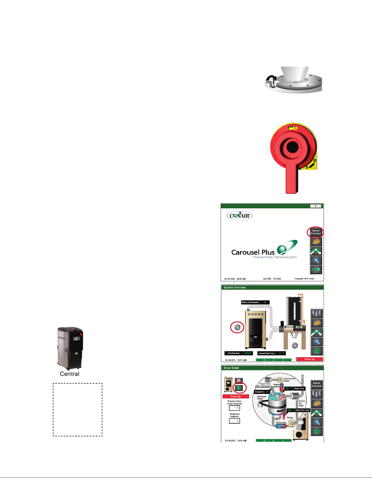
H o w t o U s e t h e L o c k o ut De v i c e
CAUTION: Before performing maintenance or repairs on this product, you should discon-
nect and lockout electrical power sources to prevent injury from unexpected energization or
start-up. A lockable device has been provided to isolate this product from potentially hazardous electricity.
Lockout is the preferred method of isolating machines or equipment from energy sources.
Your Conair product is equipped with the lockout device pictured below. To use the lockout
device:
1
Stop or turn off the equipment.
2
Isolate the equipment from the electric power. Turn the rotary
disconnect switch to the OFF, or “O” position.
3
Secure the device with an assigned lock or tag. Insert a lock or tag
in the holes to prevent movement.
4
The equipment is now locked out.
WARNING: Before removing lockout devices and returning switches to the ON position, make sure that all personnel are clear of the machine, tools have been
removed, and all safety guards reinstalled.
To restore power to the dryer, turn the rotary disconnect back to the ON position:
1
Remove the lock or tag.
2
Turn the rotary disconnect switch to the ON or “I” position.
1 - 6 l In tr o du ct i on
Page 13

S E C T I O N
2
D e script i o n
W h a t is th e Ca ro us el Pl us W Ser i e s Dr ye r? . . . . . . . 2- 2
Typ ic al A pp li ca t i o n s . . . . . . . . . . . . . . . . . . . . . . 2- 2
H o w I t Wo r k s . . . . . . . . . . . . . . . . . . . . . . . . . . 2 -4
S p e c i f i c a ti on s: C a r o u s e l Pl us W S er ie s
D r y er . . . . . . . . . . . . . . . . . . . . . . . . . . . . 2- 6
C a r o u s e l Pl us W S er ie s D ry er Op ti on s . . . . . . . . . . 2- 7
D e scr i pt io n
2
D e s c ri p ti o n l 2 - 1
Page 14

W h a t i s t h e C a r o use l P l u s W S e r i e s
D r y er?
The Carousel Plus W Series dehumidifying dryer produces hot, low-dewpoint air that
removes moisture from hygroscopic plastics. The dryer pulls warm, moist air from a drying
hopper and circulates it through a dehumidifying desiccant wheel. The dryer then heats the
air to the drying temperature you selected and circulates it through the material in the hopper.
The dryer’s closed-loop design ensures a continuous supply of hot, dehumidified air while
preventing contamination from moisture in the plant.
Ty p i c al Ap p l i c a ti o n s
1 Dryer on the floor; hopper on the throat.
2 Hopper on a floor stand; the dryer next to it.
3 Dryer on the floor, multiple hoppers in central configuration (ResinWorks) with separate
heat source for each hopper.
When supplied for central drying applications,
the W series dryer is not equipped with a
process heater. Therefore, as a central dryer,
the W dryer will only supply dry air to the
hoppers.
2 - 2 l De sc r ip ti o n
( C o nt i nu ed )
Page 15

Ty p i c al Ap p l i c a ti o n s ( co n ti nu ed )
The W Series Dryer can be used successfully in applications that require:
• A contamination-free drying environment.
• Drying temperatures within the ranges shown in the following table:
Model Drying Temperature Range
Low temperature (with precooler)* 100° - 150°F {38° - 66°C}
Standard 150° - 240°F {66° - 116°C}
High heat (with aftercooler)* 150° - 375°F {66° - 191°C}
Low-high (with aftercooler & precooler)* 100° - 375°F {38° - 191°C}
* See page 3-13 and Appendix B and C.
• Throughput rates of 150 to 400 lbs {68.1 to 149.2 kg} per hour (some materials can be -
run at a higher rate).
• Dewpoints of -40°F {-40°C}.
Use the aftercooler when:
• You are drying at temperatures over 240°F {116°C}.
• Throughput rates are less than 50% of the dryer’s rated capacity.
• You are pre-drying material at temperatures over 150°F {66°C}
Standard Dryer Features
• Dewpoint monitor / dewpoint control
• Audible and visual alarm
• Temperature setback
D e scr i pt io n
2
D e s c ri p ti o n l 2 - 3
Page 16

H o w I t Work s
The W dryer achieves continuous, closed loop drying by passing air simultaneously through
two heaters and a continuously rotating desiccant wheel.
THE PROCESS (DRYING) CYCLE
The process blower pulls moist air from the top of the drying hopper. The air passes
through the process filter and aftercooler into the desiccant wheel, where moisture is
removed. The now dry air moves through the optional precooler (if installed) and process
heater, where it is heated to the drying temperature selected by the operator. The hot, dry air
is delivered to the hopper where a spreader cone evenly distributes the air through the material.
THE PROCESS (DRYING) CYCLE
The process blower pulls moist air from the top of the drying hopper. The air
passes through the process filter and aftercooler, then into the desiccant
wheel, where moisture is removed. The dry air is delivered to the hopper
(after it passes through the optional precooler, if installed) where a spreader
cone evenly distributes the air through the material.
The Regeneration Cycle
The regeneration blower pulls air through the regeneration filter into the dryer’s regeneration
heater. The air is heated to 350° F {177° C} before it is pushed into the “wet” section of the
wheel. The hot air purges moisture from the desiccant. The moist air is blown out the
exhaust at the back of the dryer.
The Cooling Cycle
Regenerated desiccant must be cooled before it rotates back into the process cycle. The
process blower pushes a small amount of air through the cooling section of the desiccant
wheel. The cooling air then passes through the aftercooler and repeats the circuit.
2 - 4 l De sc r ip ti o n
Page 17

R
EGENERATION
AIR FILTER
DESICCANT
WHEEL
REGENERATION
BLOWER
REGENERATION
H
EATER
HIGH TEMP
SHUTOFF
REGENERATION
RTD
HOPPER
PROCESS
BLOWER
RETURN
AIR
FILTER
4 PROCESS FILTER STATUS
RETURN
AIR
RTD
P
ROCESS
R
TD
2 SETBACK TEMPERATURE
H
IGH TEMP
SHUTOFF
PROCESS
HEATER BOX
7 PRECOOLER
7
DRYER OPTIONS
3 DEWPOINT MONITOR / CONTROL
PROCESS
COOLING
REGENERATION
2
3
4
P
ROCESS
P
ROTECTION
R
TD
REGENERATION
OUTLET
RTD
6
6 PHASE ROTATION PROTECTION
AFTERCOOLER
A
LARM LIGHT
A
LARM BELL
5 CURRENT METER
5
5
1 PROCESS CFM MONITOR
1
H o w I t Work s ( c o nt i nu ed )
D e scr i pt io n
2
The components identified by this type of box in the drawing are not supplied with the
W series dryer when it is configured as a central dryer.
D e s c ri p ti o n l 2 - 5
Page 18

S p e c i f ic a t i o n s: C ar o u s e l P l us W S e ri e s
D r y ers
A
B
C
MODEL W150 W200 W300 W400
Performance characteristics (with full hopper)
Drying temperature
†
All models 100°- 375°F {38°- 191°C} with options
Dew point All models -40°F {-40°C}
Dimensions inches {cm}
A - Height 64.3 {163.3}
B - Overall width 29 {73.7}
C - Depth 51.5 {130.8}
Outlet/inlet tube size OD 2.5 {63.5} 5.0 {127.0} 5.0 {127.0} 5.0 {127.0}
Weight lbs {kg}
Standard dryer installed 600 {272} 660 {300} 710 {322} 760 {345}
Voltage - Full load amps Standard/Central drying
230 V/3 phase/60 Hz 47.1 / 16.7 57.6 / 19.9 67.7 / 30.0 N/A
400 V/3 phase/50 Hz
*
23.4 / 8.9 32.1 / 10.4 37.9 / 16.2 64.5 / 21.1
460 V/3 phase/60 Hz 21.0 / 8.4 28.9 / 10.0 34.0 / 15.1 56.3 / 18.6
575 V/3 phase/60 Hz 16.8 / 6.7 23.7 / 8.6 27.3 / 12.2 43.2 / 13.0
Water requirements {for aftercooler or optional precooler}
Recommended temperature
Water flow
Water connections NPT 3/4 inch NPT
SPECIFICATION NOTES:
gal./min.{liters/min.}
‡
45°- 85°F
3 {11.4}
†
* Dryers running at 50 Hz will have 17% less airflow, and a 17% reduction in material throughput.
†
When drying below 150°F {66°C} a precooler is required.
‡
Temperatures above or below the recommended levels may affect dryer performance.
Tower, chiller or municipal water sources can be used.
Specifications may change without notice. Consult a Conair representative for the most current information.
APPLICATION NOTES:
All dryers are supplied with an aftercooler
as standard. The aftercooler reduces the
temperature of the return air from the drying hopper, improving the efficiency of the
desiccant. The aftercooler must be connected with the proper water flow rate and temperature to attain the rated throughput.
When to use central models
Central dryers do not have process
heaters. These models should be used
when drying multiple materials that
require different drying temperatures.
Central models dehumidify the process
air, which is then heated to the correct
setpoint by a Heater Pack mounted on the
hopper and controlled from the dryer.
When to use additional filtration
The standard return air cartridge filter is
sized for the airflow of each dryer model
and is suited for most applications. You
should consider adding an optional dust
collector and/or volatile trap if:
●
The material contains excessive fines. An
additional dust collector or cyclone will
extend time between filter cleaning.
●
The material produces volatiles during
drying which condense into a waxy or
oily residue. A volatile trap will help to
protect the desiccant.
2 - 6 l De sc r ip ti o n
TPDX018-0113
Page 19

C a r o u s el P lu s W Ser i e s D r y e r O p t i o n s
• Volatile trap (only in conjunction with aftercooler) - The volatile trap is recommended if
drying materials that produce volatile that condense into a waxy or oily residue and/or if
the material contains excessive fines.
• Precooler - The precooler reduces the temperature of air flow after the desiccant wheel
and before the process heater.
• Filter check - The Filter check sensor will activate a passive alarm when the process
filter is clogged or needs to be replaced.
• Heater current monitor - The heater current monitor measures the total amperage
across both the process and regeneration heaters and the pre-determined power consumption values for the blowers and the control.
• CFM monitor - The CFM monitor measures the cubic feet per minute of airflow across
the inlet/outlet of the process blower.
• DeviceNet or SPI communications - Allows the dryer to be networked to industrial con-
trol systems. DeviceNet communications are standard. Alternate communications are
available.
D e scr i pt io n
2
( C o nt i nu ed )
D e s c ri p ti o n l 2 - 7
Page 20

2 - 8 l De sc r ip ti o n
Page 21

I n stalla t i o n
U n p a c k i n g the Bo xe s . . . . . . . . . . . . . . . . . . . . . 3- 2
P r e p a r i n g for In st al la ti on . . . . . . . . . . . . . . . . . . 3- 3
Po si ti on in g t he D r y e r on t h e Fl oo r . . . . . . . . . . . . 3 -3
R e m o v i n g th e C a b l e Ti e fr om th e D e s i c c a n t Wh ee l . . 3 - 3
S E C T I O N
3
I n sta l la ti on
3
C o n n e c t i n g th e M a i n Po we r . . . . . . . . . . . . . . . . . 3- 4
C o n n e c t i n g th e P r o c e s s RT D Pro be . . . . . . . . . . . . 3 -5
C o n n e c t i n g th e S e t b a c k RT D Pro be . . . . . . . . . . . . 3 -5
C h e c k i n g fo r P r o p e r A ir Fl ow . . . . . . . . . . . . . . . . 3 -6
C o n n e c t i n g th e Ai r Ho se s . . . . . . . . . . . . . . . . . . 3 - 9
C o n n e c t i n g th e D r y er t o the Ho pp er . . . . . . . . . . . 3 -9
C o n n e c t i n g A ir Ho se A d a pt er s . . . . . . . . . . . . . . 3 -1 0
C o n n e c t i n g th e Af te rc oo le r . . . . . . . . . . . . . . . . 3- 11
M o u n t i n g a L o a d e r on t h e Ho pp er . . . . . . . . . . . . 3- 12
Te st in g t he I ns ta ll a t i o n . . . . . . . . . . . . . . . . . . . 3 -1 2
U s i n g Com mu ni ca t io ns ( Op ti on al ) . . . . . . . . . . . . 3 - 1 3
I n s t al l at io n l 3 - 1
Page 22

U n p a c k in g th e B o x e s
The Carousel Plus W series dryer comes in one to four boxes, depending on the model and
options ordered. The boxes could include (depending on the options selected):
• Carousel Plus W series dryer
• Delivery air hose - 10 ft {3.05 m} - Insulated with High Heat option.
• Return air hose - 10 ft {3.05 m}
• Process RTD
• Setback RTD
• User manual
1 Carefully remove the dryer and components from their shipping containers. Note that
the dryer is secured to its shipping container with straps that pass through the bottom of
the dryer frame.
2 Remove all packing material, protective paper, tape, and plastic.
3 Open the side panel and remove the cable tie securing the desiccant wheel. See
Installation section entitled, Removing the cable tie from the desiccant wheel.
4 Carefully inspect all components to make sure no damage occurred during shipping,
and that you have all the necessary hardware.
5 Take a moment to record serial numbers and electrical power specifications in the
blanks provided on the back of the User Guide’s title page. The information will be helpful if you ever need service or parts.
6 You are now ready to begin installation.
Follow the preparation steps on the next page, then choose one of the four mounting
options:
• Dryer on the floor; hopper on a floor stand (see page 3-5).
• Dryer on the floor; hopper machine mounted
• Central dryer, with ResinWorks system.
3 - 2 l In st a ll at io n
Page 23

P r e p a r in g fo r I n s t a l la t i o n
The Carousel Plus W Series Dryer is easy to install if you plan the location and prepare the
mounting area properly.
1 Make sure the mounting area provides:
❒
A grounded power source supplying the voltage and correct current for your
dryer model. Check the dryer’s serial tag for the correct amps, voltage, phase, and
cycles. Field wiring should be completed by qualified personnel to the planned location for the dryer. All electrical wiring should comply with your region’s electrical
codes.
❒
A source of water, if you have an aftercooler and/or optional precooler.
The W dryer’s aftercooler and optional precooler require 3 gals./min. {11.4 liters/min.}
tower, city, or chiller water at temperatures of 45° to 85°F {7° to 29°C}. Pipe should
be run to the planned dryer location. Use flexible hose to connect the water pipes to
the aftercooler and/or optional precooler.
❒
Minimum clearance for safe operation and maintenance.
You should maintain 24 in. {61 cm} clearance on all sides of the dryer.
Posit i o n i n g t he Dr y e r o n t h e F l oo r
Material and conveying
✒
lines installed. If you
plan to use vacuum or
compressed air loaders
to fill the hopper, install
conveying lines to the
drying hopper location.
I n sta l la ti on
3
1 Lift the dryer from the shipping container using a fork truck.
2 Position the dryer on the floor near the processing machine. Make sure the
location allows for the connection of all hoses.
R e m o v in g t h e C a b l e T i e f r o m t h e
D e s i c c an t Wh e e l
1 Open the dryer side panels and remove the cable tie securing the desiccant wheel, if
it was not done while unpacking the dryer.
Desiccant cable tie
I n s t al l at io n l 3 - 3
Page 24

C o n n e c ti n g t h e M a i n Po w e r
CAUTION: Always disconnect and lock out the main power sources before making electrical con-
nections. Electrical connections should be made only by qualified personnel.
1 Open the dryer’s electrical enclosure. Turn the discon-
nect dial on the dryer door to the Off or “O” position.
Lock out the main power (see Page 1-6 for complete
lock out information). Turn the captive screw, and swing
the door open.
2
Insert the main power
side of the enclosure or the rear of the dryer. ( The
dryer’s electrical wire connection location was a factory
option and may be connected through the front or the
rear of the dryer.) Secure the wire with an appropriate
strain relief.
wire through the knockout in the
IMPORTANT: Always refer to the
wiring diagrams that came with
your dryer before making electrical
connections.
3 - 4 l In st al la ti on
Connect the power wires
3
to the three terminals at the top of the power disconnect.
4 Connect the ground wire to the ground lug as shown in the photo.
Page 25

C o n n e c ti n g t h e P r o c e ss RTD P r obe
The process RTD probe monitors the temperature of the drying air as it enters the hopper. If
the probe is not installed correctly, temperature readings will be inaccurate.
1 Insert the probe at the inlet to the
hopper. The end of the probe must not touch the
walls of the inlet. The tip of the probe should be
approximately in the center of the tube. Tighten the
compression fitting to lock the probe in place.
Setback RTD
Process RTD
2 Plug the probe’s cable
into the receptacle
labeled process on the left
side of the electrical
enclosure. Hand tighten
the connector. Coil any
excess cable and secure it
with a wire tie.
C o n n e c ti n g t h e S e t b a ck RTD
1 Insert the probe in the hopper outlet at the top of the hopper. The end of the probe
must not touch the walls of the inlet. The tip of the probe should be approximately in the
center of the tube. Tighten the compression fitting to lock the probe in place.
2 Plug the probe’s cable into the receptacle labeled setback on the left side of the elec-
trical enclosure. Hand tighten the connector. Coil any excess cable and secure it with a
wire tie.
I n sta l la ti on
3
When configured as
a central dryer, monitoring the drying air
temperature is not
necessary since there
is no process heater
in the system.
Therefore, installation and connection
of the RTD probe
and/or setback probe
is not applicable.
I n s t al l at io n l 3 - 5
Page 26

O
FF
O
O
N
I
✐
NOTE: Users must be
logged in as Maint 1
(user level 3) in order to
perform this operational
test.
C h e c k i ng for Pr o p e r A i r F l o w
IMPORTANT: This procedure must be performed before loading material into the hopper.
CAUTION: If the airflow direction is incorrect due to improper phase connection, material from
the hopper can be pulled back into the dryer, causing permanent damage to this equipment.
1 Turn on the main power to the dryer. Make sure the dryer’s disconnect dial is in the ON
position. This powers up the control and the display will illuminate.
When configured as a
central dryer, the drying temperature can
not be set since there
is no process heater in
the system.
2 From the Home Screen , press the “Setup” button.
WARNING: All wiring, disconnects, and fuses should be installed by qualified electrical technicians in accordance with electrical codes in your region. Always maintain a safe ground. Do not operate the equipment at power levels other than what
is specified on the machine serial tag and data plate.
3 - 6 l In st a ll at io n
Page 27

C h e
e
3 Pr
e
4 Pr
e
5 Pr
powe
e
Pr
one
n
k i
c
O S
/
I
“
e
h
t
s
s
we
o
p
e
h
t
s
s
“De
ss the
button to star
r
button agai
ss the
ond to stop the
c
se
d )
i n u e
n t
o
c
(
w
l o
F
r
i
A
r
e
p
o
r
P
r
o
f
g
.
n
o
t
t
u
b
”
t
s
Te
O
/
I
“
e
h
t
n
e
h
t
d
n
a
n
o
t
t
u
b
”
p
u
t
e
.
e
d
o
m
t
s
e
t
e
l
b
a
n
e
o
t
”
e
d
o
M
t
s
Te
O
/
I
r
e
y
Dr
“
e
d
i
s
e
b
n
o
t
t
u
b
r
I n sta l la ti on
3
”
r
owe
l
B
r
Ai
y
r
ve
i
l
.
r
owe
bl
t the
about
r
n afte
.
r
owe
bl
✐
NOTE: On initial test (first time
in Dryer I/O Test Mode) the
process blower will automati-
cally start. Press the button
beside “Delivery Air Blower” to
stop the blower.
ear the
n
d
n
a
h
your
ld
6 Ho
feel
ld
u
sho
u
o
Y
tlet.
u
o
ir
a
tlet.
u
e o
th
of
t
u
o
CAUTION: Hot surface Do not place
your hand directly on the delivery air
outlet. The outlet and the air can get
hot enough to burn your hand.
If air flow is incorrect disconnect
7
power, follow proper lockout proce
dures and swap any 2 of the 3 main
power wires.
delivery
lowin
air b
Return
g
-
Air Inlet
Dry Delivery
Air
Moisture
Exhaust
( C o nt i nu ed )
I n s t al l at io n l 3 - 7
Page 28

C h e c k i ng for Pr o p e r A i r F l o w ( co nt i nu ed )
✐
INSTALLATION NOTE: Models 150, 200, 300, and 400
These models use a three-phase process blower. If the dryer shuts down and a Process Loop
Break shutdown alarm is indicated within the first few minutes of operation, check for proper air
flow or check the Process RTD for proper installation.
If the air flow is reversed, the process blo wer is turning in the wrong direction. Turn
off and lock out the main power source. Open the electrical enclosure and reverse
any two leads connecting the main power supply to the dryer.
LEADS
3 - 8 l In st a ll at io n
WARNING: All wiring, disconnects, and fuses should be installed by qualified
electrical technicians in accordance with electrical codes in your region. Always
maintain a safe ground. Do not operate the equipment at power levels other
than what is specified on the machine serial tag and data plate.
Page 29

C o n n e c ti n g t h e A i r H o s e s
Using the two flexible hoses provided, connect the inlets and outlets of the drying hopper to the dryer. If you have positioned the dryer on the floor or mounted it to an optional floor stand, make sure the dryer is located as close as possible to the hopper to reduce
heat loss. (10 ft {3.05 m} of hose supplied)
✐
NOTE: If you have ordered an insulated hose, it should be installed between the dr yer outlet and
the hopper inlet, see step 2.
1 Attach one hose from the return air
inlet of the dryer to the return air
outlet from the top of the hopper.
Return
Air Inlet
Dry
2 Attach one hose from the delivery
air outlet of the dryer to the delivery
air inlet of the hopper.
Delivery
Air
I n sta l la ti on
3
3 Secure hoses with clamps.
The hose clamp should be secured at
least 1/4 in. {0.64 cm} from the end of
the inlet or outlet tube.
C o n n e c ti n g t h e D r ye r to th e Ho p p e r
W 150 has a 2 1/2 inch {63.5 mm} inlet and outlet hose connections.
W 200, W 300 and W 400 have a 5 inch {127 mm} inlet and outlet hose connections.
If your dryer hose connection and your hopper hose connection are not the same
size, you will need a hose adapter. Contact Conair Parts 1-800-458-1960.
✐
NOTE: Do not allow the
flexible hoses to kink or
crimp.
✐
NOTE: Water to cooler
should be turned off
when the dryer is not
running to prevent
condensation
.
I n s t al l at io n l 3 - 9
Page 30

C o n n e c ti n g A i r H o s e A d a pte r s
Depending on the hopper you purchased you may need to install an air hose adapter to connect the hopper to your dryer.
To connect the air hose adapter:
1 Place high temperature gasket half way down over the dryer outlet to the
hopper.
2 Place hose adapter inside high temperature gasket flush to the dryer outlet, secure
with pressure clamp.
Pressure clamp
3 Attach the hopper inlet hose over the adapter, secure with clamp.
3 - 1 0 l In st al la ti o n
( C o nt i nu ed )
Page 31

C o n n e c ti n g t h e A f t e r co o l e r ( O pt io n al )
The aftercooler and optional precooler require a source of city, tower, or chiller water and a
discharge or return line. You can use water at temperatures of 45 to 85°F {7 to 29°C}. But
the water flow should be at least 3 gal/min {11.4 liters/min}. See Appendix B for installation and water connection instructions for the optional precooler.
1 Secure the aftercooler assembly in the after-
cooler housing using the six screws.
Aftercooler
2 Connect the water supply line to the aftercool-
er inlet. If a manual shut off valve is used, it
should be mounted on
the inlet line.
TIP: Make the water supply and dis-
✒
charge / return connections with
flexible hoses at least 24 in.
{61 cm} long. This allows you to
easily remove the aftercooler
assembly for cleaning.
I n sta l la ti on
3
3 Connect the water discharge or return line to
the aftercooler outlet.
IMPORTANT: Turn the water off when the dryer is not in use to preventcondensation.
TIP: If an optional flow control is also
✒
being installed with the aftercooler,
the manual shut off valve should be
installed on the inlet line for the flow
control.
I n s t al l at io n l 3 - 1 1
Page 32
M o u n t i ng a L o ad e r o n t h e H o p p e r
If you have a Conair loader or vacuum receiver, you can use the
flange and mounting clips provided on the top of the hopper.
Refer to the manuals that came with your receiver or loader for
detailed installation instructions.
Tes t i n g t h e I n sta l l a t ion
You have completed the installation. Now it’s time to make sure
everything works.
1 Make sure there is no material in the hopper. If you have
mounted a loader or vacuum receiver on the hopper, disconnect
the material inlet hose at the source or turn the loader off.
2 Turn on the main power to the dryer. Make sure the dryer’s
disconnect dial is in the ON position. This powers up the control and the display lights will illuminate.
3 From the Home Screen, press the
“System Overview” button.
When configured
as a central dryer,
the drying temperature can not be
set since there is
no process heater
in the system.
3 - 1 2 l In st al la ti o n
4 From the Overview Screen, press the
magnifying glass button beside the
dryer. (Also referred to as the “Dryer
Zoom” button.)
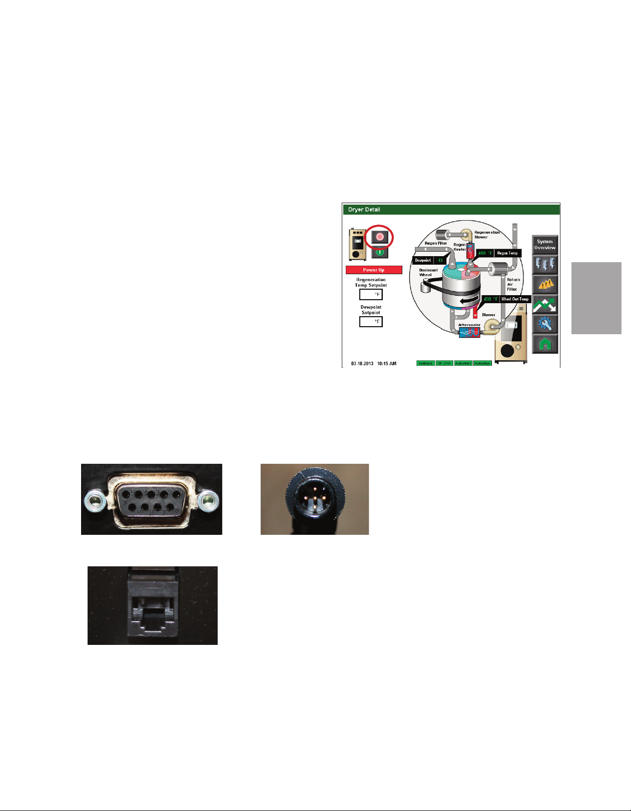
5 From the Dryer Screen, verify that set-
points are correct, and press the dryer
start button.
125
-40
350
( C o nt i nu ed )
Page 33
Tes t i n g t h e I n sta l l a t ion (c o n ti nu ed )
If everything is installed correctly:
• The regeneration and process blowers turn on
• The regeneration heater turns on
• The process heater will energize (if configured as a stand alone dryer)
• The dryer’s desiccant wheel starts turning. (If the desiccant wheel does
not turn, turn off the dryer, disconnect from power, and verify that the desiccant
wheel tie has been removed
6 From the Dryer Detail screen, press the dryer stop button.
If everything is installed correctly:
• The blowers will continue running as needed to cool the
heaters. (Until regeneration heaters are less than 150°F
{66°C}.)
7 The test is over. If the dryer performed the normal operating
sequences as outlined, reconnect the material source to the
optional hopper receiver and begin normal operation. If it did
not, refer to the Troubleshooting section of the User Guide.
125
-40
IMPORTANT: Be sure the cable tie
has been removed from the desic-
cant wheel.
I n sta l la ti on
3
U s i n g C o m m un i c a t i on s ( O p ti o na l)
To use the optional Modbus, Ethernet, SPI or standard DeviceNet communications, see
the Addendum for hardware installation and configuration.
SPI connection
Ethernet connection
DeviceNet connection
✐
NOTE: These communications can be left disconnected, if not in use.
I n s t al l at io n l 3 - 1 3
Page 34

3 - 1 4 l In st al la ti o n
Page 35

O p eratio n
The Dryer System Control Panel . . . . . . . . . . . . . . . . . . . . . . . . . . . . . . . . . 4-2
How to navigate the Control Screens. . . . . . . . . . . . . . . . . . . . . . . . . . . . . . 4-3
DC-T Control Panel . . . . . . . . . . . . . . . . . . . . . . . . . . . . . . . . . . . . . . . . . . . 4-6
Operation - ResinWorks Configuration . . . . . . . . . . . . . . . . . . . . . . . . . . 4-7
Control Function Flow Charts . . . . . . . . . . . . . . . . . . . . . . . . . . . . . . . 4-8
Control Function Descriptions - ResinWorks Configuration . . . . . . . . 4-16
Operation - Stand Alone Dryer Configuration . . . . . . . . . . . . . . . . . . . . 4-45
Control Functions Flow Chart . . . . . . . . . . . . . . . . . . . . . . . . . . . . . . 4-46
S E C T I O N
4
O p era tio n
4
Control Function Descriptions - Standard Configuration . . . . . . . . . . 4-56
General Operation - Stand Alone and
ResinWorks Dryer Configuration . . . . . . . . . . . . . . . . . . . . . . . . . . 4-81
DC-T Security Levels . . . . . . . . . . . . . . . . . . . . . . . . . . . . . . . . . . . . 4-82
Starting the Dryer. . . . . . . . . . . . . . . . . . . . . . . . . . . . . . . . . . . . . . . 4-83
Adjusting the Temperature Setpoint . . . . . . . . . . . . . . . . . . . . . . . . . 4-84
Stopping the Dryer . . . . . . . . . . . . . . . . . . . . . . . . . . . . . . . . . . . . . . 4-85
Stopping the Dryer in An Emergency . . . . . . . . . . . . . . . . . . . . . . . . 4-86
Understanding the Control LED . . . . . . . . . . . . . . . . . . . . . . . . . . . . 4-86
Alarm Email and Text Notification. . . . . . . . . . . . . . . . . . . . . . . . . . . 4-87
Ethernet TCP/IP Address Setup to Enable Email/Text Notification . . . 4-87
Email Alarm Activation and Address Setup . . . . . . . . . . . . . . . . . . . . 4-88
Configuring the Email and Text Addresses . . . . . . . . . . . . . . . . . . . . 4-89
Text Messaging Addressing . . . . . . . . . . . . . . . . . . . . . . . . . . . . . . . 4-90
Enabling and Disabling Notification for Individual Alarms . . . . . . . . . 4-90
DC-T Web Access Logon and Security . . . . . . . . . . . . . . . . . . . . . . . 4-94
Web Server Setup Screen . . . . . . . . . . . . . . . . . . . . . . . . . . . . . . . . 4-95
O p e r at io n l 4 - 1
Page 36
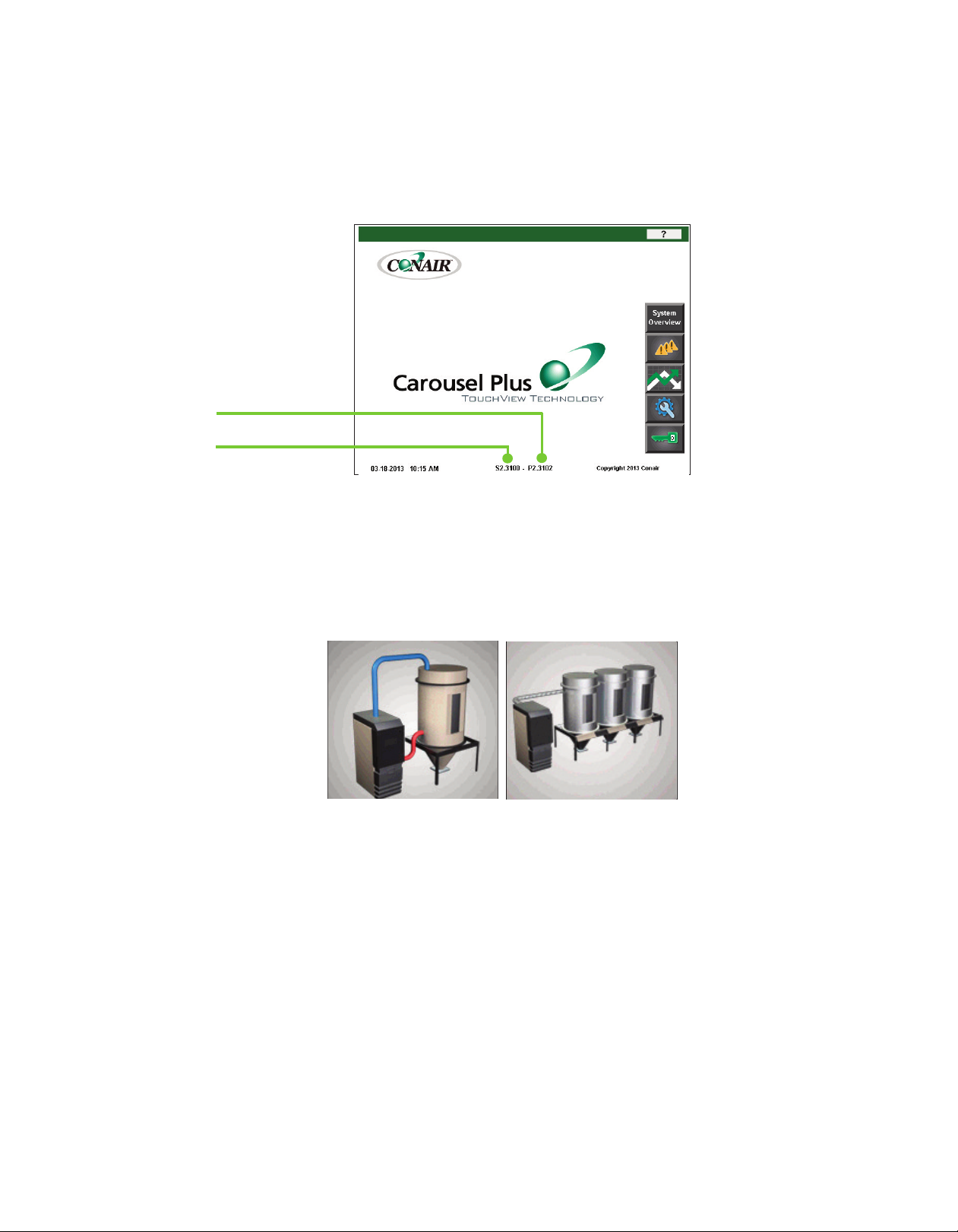
D r y er S ys t e m C o n t rol Panel
✐
NOTE: The bottom of the Home
screen displays valuable infor-
mation, including the current
date and time, the HMI software
version, the dryer board ver-
sion, and Conair’s copyright.
The software version and board
version will be helpful for serv-
ice and troubleshooting purpos-
es.
Dryer board version
HMI software version
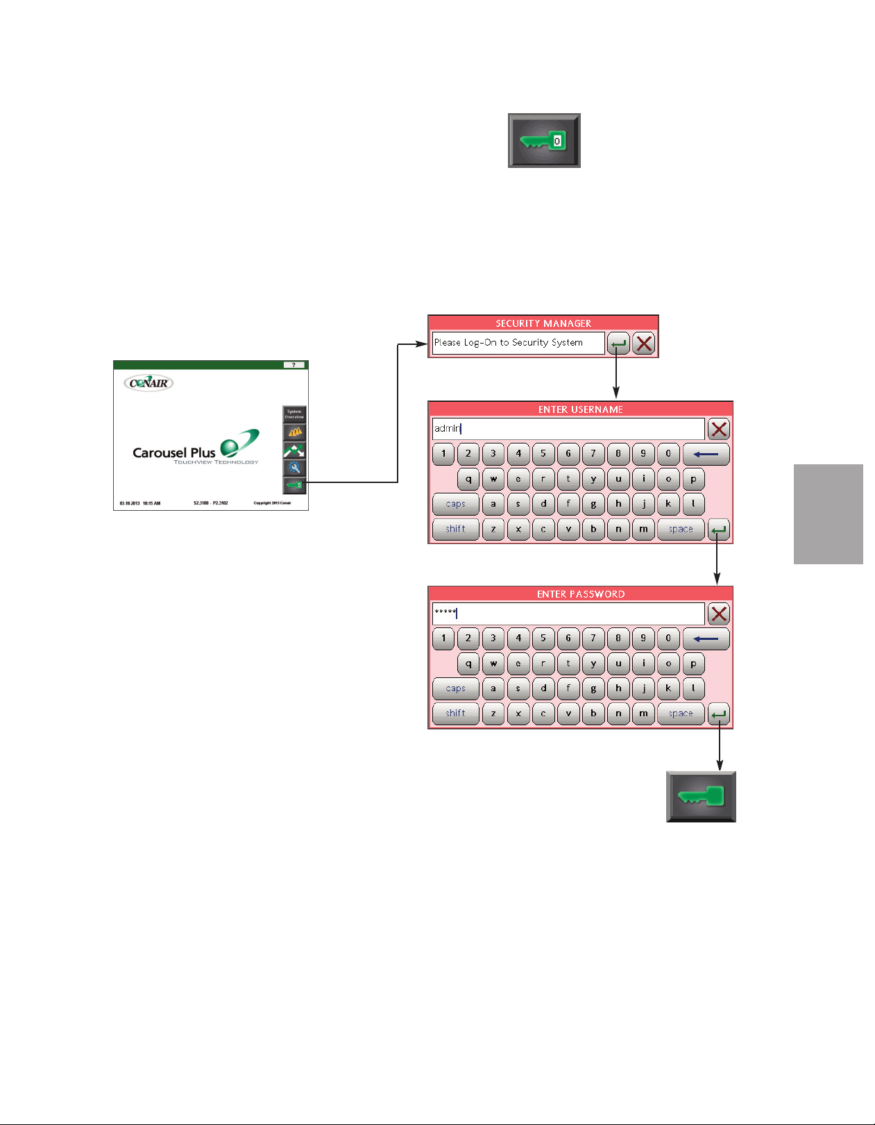
On power-up, the Carousel Plus Dryer control displays the initial system Home screen.
At start-up, the system security level is "Default". Once the operator clicks the Login button and enters the user name and password, access is permitted to various areas of the control. The user, depending on security access level, can access the various system and setup
screens for the entire Carousel Plus Dryer system.
4 - 2 l O pe ra ti on
Stand alone dryer
Central or ResinWorks dryer
Your DC-T Carousel Plus Dryer Control has been configured at the factory based on the
configuration you chose when placing the order. The DC-T can be configured for use with
a ResinWorks dryer with multiple hoppers, a central dryer with separate heat source to
multiple hoppers, or as a stand alone dryer with a single hopper. Once this factory configuration is set (based upon your order) a customer can not change this configuration. The
screens, the screen flow, and operation will differ greatly depending on which configuration
you are using. The Operation section of this user guide covers each of the three configurations individually.
Page 37
H o w t o N a v i g a te th e Co n t r o l S c re e n s
Navigate through the DC-T control screens by touching any navigation "buttons" and/or
magnifying glass icons.
Navigation Buttons
Touching the navigation
buttons will take the
user to the control
screen selected.
O p era tio n
4
Magnifying Glass Icons
Touching the magnifying glass icons will
take the user to screens that contain
detailed information about the system component selected.
(continued)
O p e r at io n l 4 - 3
Page 38
H o w t o N a v i g a te th e Co n t r o l S c re e n s
( c o nt i nu ed )
The user name, password and other information can be entered using the pop-up keyboard
window that appears when an appropriate field is touched.
✐
NOTE: Changing most parame-
ters will require a user login at
the proper security level.
the Operation section of this
User Guide entitled DC-T
System Security Levels for
more information about user
login levels and access.
See
350
Set points can be entered within fields with a heavy black boundaries. Values shown within
colored boxes are “actual” values and can not be changed.
Actual Values
(NonChangeable)
Set point Field
(User Changeable)
350
-40
4 - 4 l O pe ra ti on
(continued)
Page 39
H o w t o N a v i g a te th e Co n t r o l
S c r e e n s ( c on t in ue d)
All beveled grey buttons on the DC-T control screen are selectable and will direct you to
another screen. At any point, pressing the Home button will return you to the home screen.
O p era tio n
4
O p e r at io n l 4 - 5
Page 40
Screen name
Indicates what screen
you are currently
l
ooking at.
T h e D C - T C o n t ro l Panel
Below is a screen from the DC-T while in operation. This screen is shown as a sample of
functionality of a typical DC-T screen. See the functional descriptions below. The following pages are helpful in understanding how to use the DC-T Control.
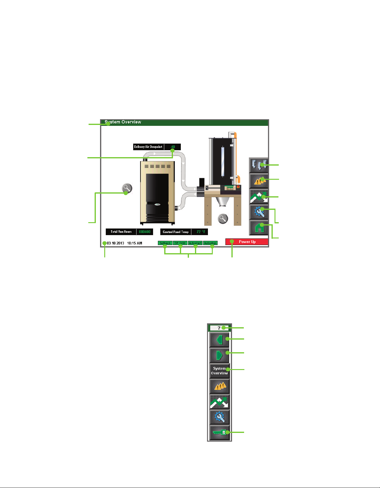
Displayed data
D
isplays the current
live data for the piece
o
f equipment. If this
data displays as all
dashes or blanks,
t
here is a communi-
cation error.
Magnifying glass /
“Zoom button”
Use these buttons to
zoom to more information about the equipment. In this example,
this Dryer Zoom button
takes you to the
ResinWorks Dryer
screen.
Date and Time
This area displays the
current date and time.
Enabled Options
This area displays icons to let you
see what options are currently
being used. For example, this dryer
is using the Temperature Setback
feature, the Dewpoint Control, and
Autostart and Autostop.
✐
NOTE: Depending upon which options were
ordered or are enabled, different icons may
appear as available or una vailable.
System status
This area displays messages to let you know the
current status of the
dryer.
Help Overview button
Help for the current screen.
Previous button
Returns to the previous list of items.
Next button
Moves to the next list of items.
Hopper Selection button
Go to the Hopper Selection
s
creen.
Alarms button
Go to the Alarms area.
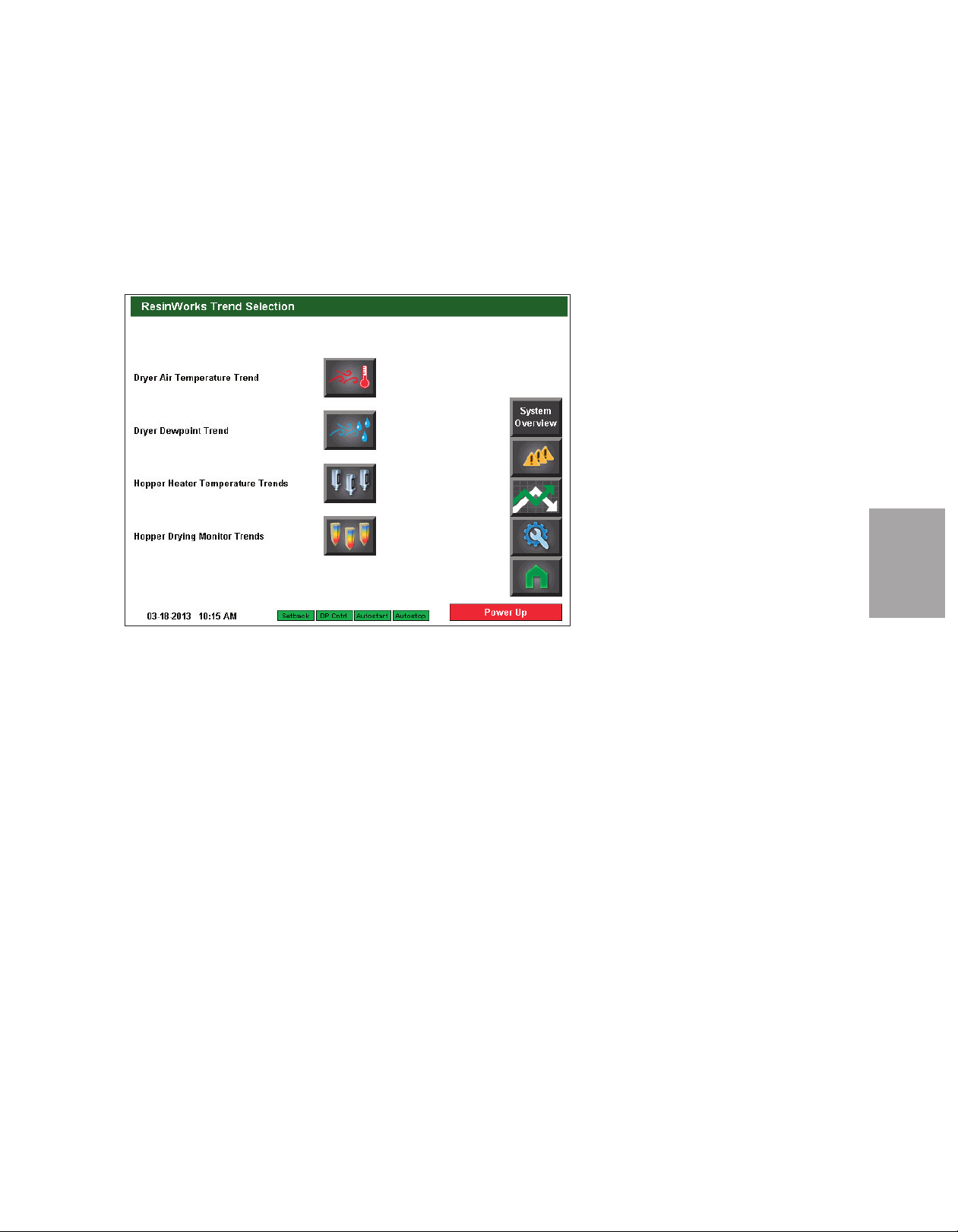
Trending buttons
Go to the Trend Selection
screen.
Setup button
Go to the Setup screen.
Home button
Go to the Home screen.
4 - 6 l O pe ra ti on
System Overview button
Go to the System Overview screen.
Login/Logout button
This button is used to login or log
out as a user.
Page 41

O p eratio n - R e s i n W orks C o n f i g u r a t i o n
The following pages (screen flow charts, screen descriptions, and basic operation) describe
the operation of the dryer when factory configured as a ResinWorks dryer attached to multiple hoppers, or as a central dryer attached to one or multiple hoppers with delivery air heat
at each hopper.
O p era tio n
4
O p e r at io n l 4 - 7
Page 42

C o n t r o l F u nc t i o n F l o w C ha r t s
F ro m th e Hom e sc r ee n
Home
Help
Overview
ResinWorks
Overview
Active
Alarms
Trend
Selection
4 - 8 l O pe ra ti on
Setup
Login/
Logout
Page 43
C o n t r o l F u nc t i o n F l o w C ha r t s
F ro m th e Ove r vie w sc r ee n
System Overview
Dryer Detail
Hopper
Selection
O p era tio n
4
In
eq
In
d
iv
id
u
al h
op
p
er
s
creen
Ready to Run
d
iv
id
u
al h
op
p
er DM3-e (if
u
ip
p
ed
) s
et
t
in
g
s
s
creen
In
d
iv
id
u
al h
op
p
er
settings screen
O p e r at io n l 4 - 9
Page 44

Home
C o n t r o l F u nc t i o n F l o w C ha r t s
F ro m th e Ala r m s c re e n
Alarms
4 - 1 0 l O pe ra ti on
Page 45

C o n t r o l F u nc t i o n F l o w C ha r t s
F ro m th e Tr e nd S ele c ti o n s c ree n
Air Temp.
Trending
DM3-e
Hopper
Trend
Selection
DM3-e
Individual
Hopper
Trend
Trend
Selection
Dewpoint
Trending
O p era tio n
4
Hopper
Heater
Trend
Selection
Individual
Hopper Air
Temp.
Trend
( C o nt i nu ed )
O p e r at io n l 4 - 1 1
Page 46

Setup
C o n t r o l F u nc t i o n F l o w C ha r t s
F ro m th e Set u p s c re e n
ResinWorks
Setup
RW Dryer
Options
Autostart
Setup
or
4 - 1 2 l O pe ra ti on
Hopper
Names
Hopper
Setup
Hopper
Comms
( C o nt i nu ed )
Page 47

C o n t r o l F u nc t i o n F l o w C ha r t s
F ro m th e Set u p s c re e n (c on ti n ue d)
Setup
Set Time
and Date
Regen
Setup
Regen PID
Auto Tune
O p era tio n
4
PID Values
Reset To
Default
Dewpoint Setup
Temp Sensor Setup
Digital Output Test
(continued)
I/O Setup
Digital
I/O
Status
O p e r at io n l 4 - 1 3
Page 48
Setup
C o n t r o l F u nc t i o n F l o w C ha r t s
F ro m th e Set u p s c re e n (c on ti n ue d)
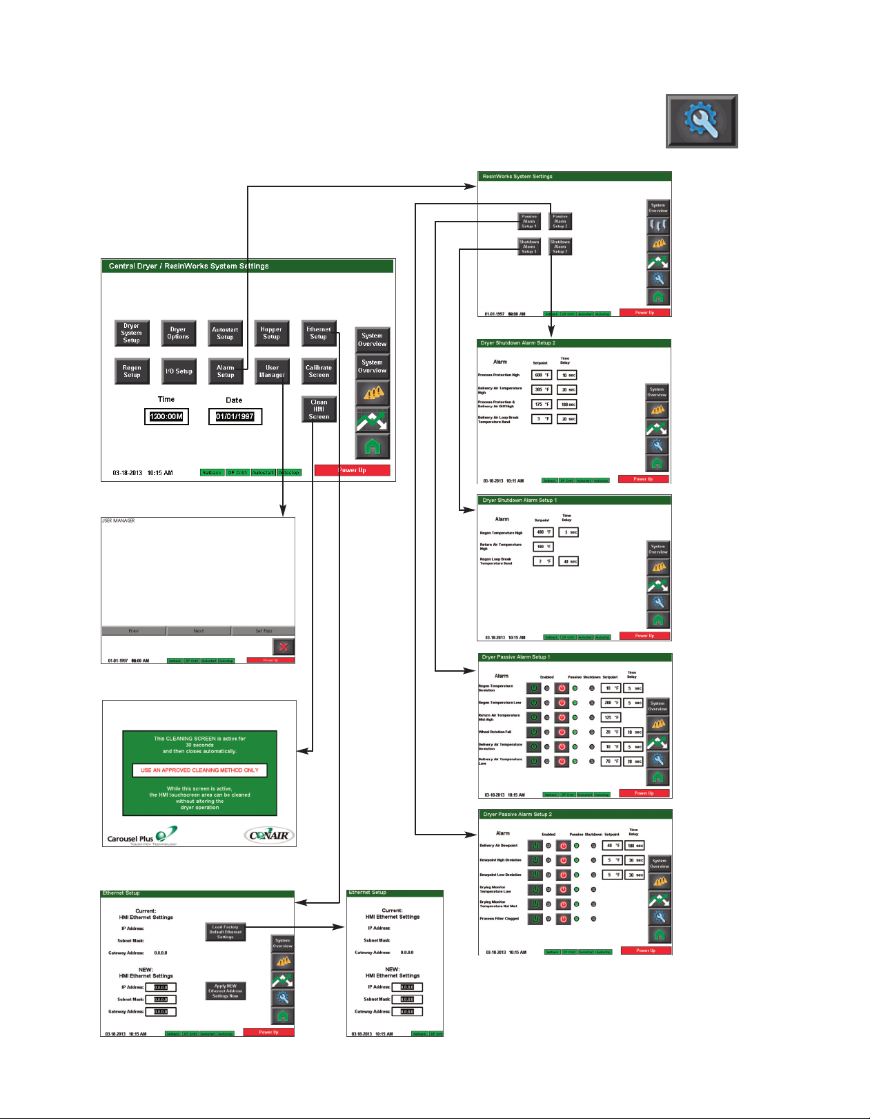
Alarm
Setup
Shutdown
Alarm
Setup 2
User Manager
Clean Screen
Ethernet Setup
Shutdown
Alarm
Setup 1
Passive
Alarm
Setup 1
Passive
Alarm
Setup 2
4 - 1 4 l Op er at io n
Page 49
C o n t r o l F u nc t i o n F l o w C ha r t s
F ro m th e Log i n/ L og o ut s c re e n
Security Manager
Home
O p era tio n
4
3
O p e r at io n l 4 - 1 5
Page 50
✐
NOTE: On this Overview screen,
live data is displayed. Data is
displayed as colored text inside a
solid black box. Set points boxes
are white with heavy black borders. Set points can be changed,
if the user has logged in at the
proper security level, by pressing
the set point boxes. This will
launch a pop-up keypad window
that can be used to change the
See Operation section
set point.
entitled, How to Navigate the
Control Screens.
set point value has been entered,
press the "Enter" key to lock in
the new set point.
After the new
C o n t r o l F u nc t i o n D e s cr i p t i o ns - R W
C o n f i g ur a t i o n
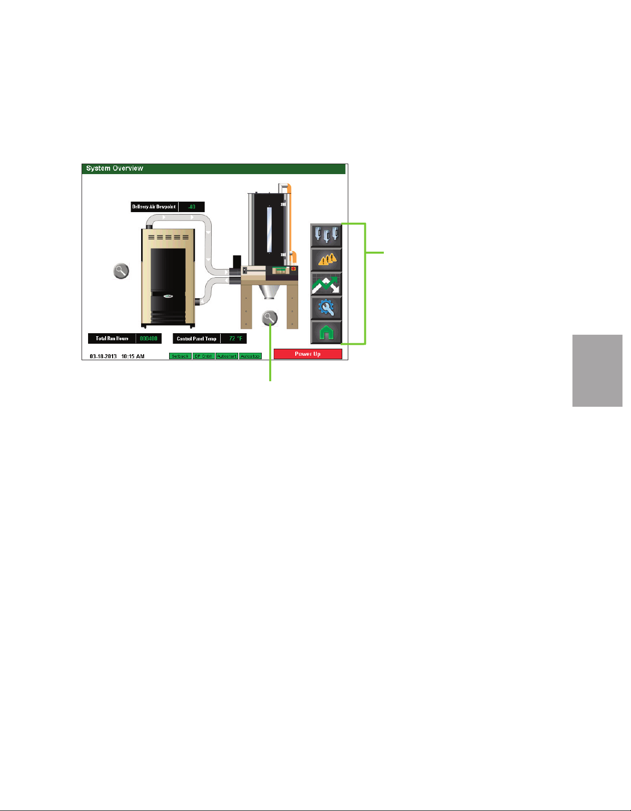
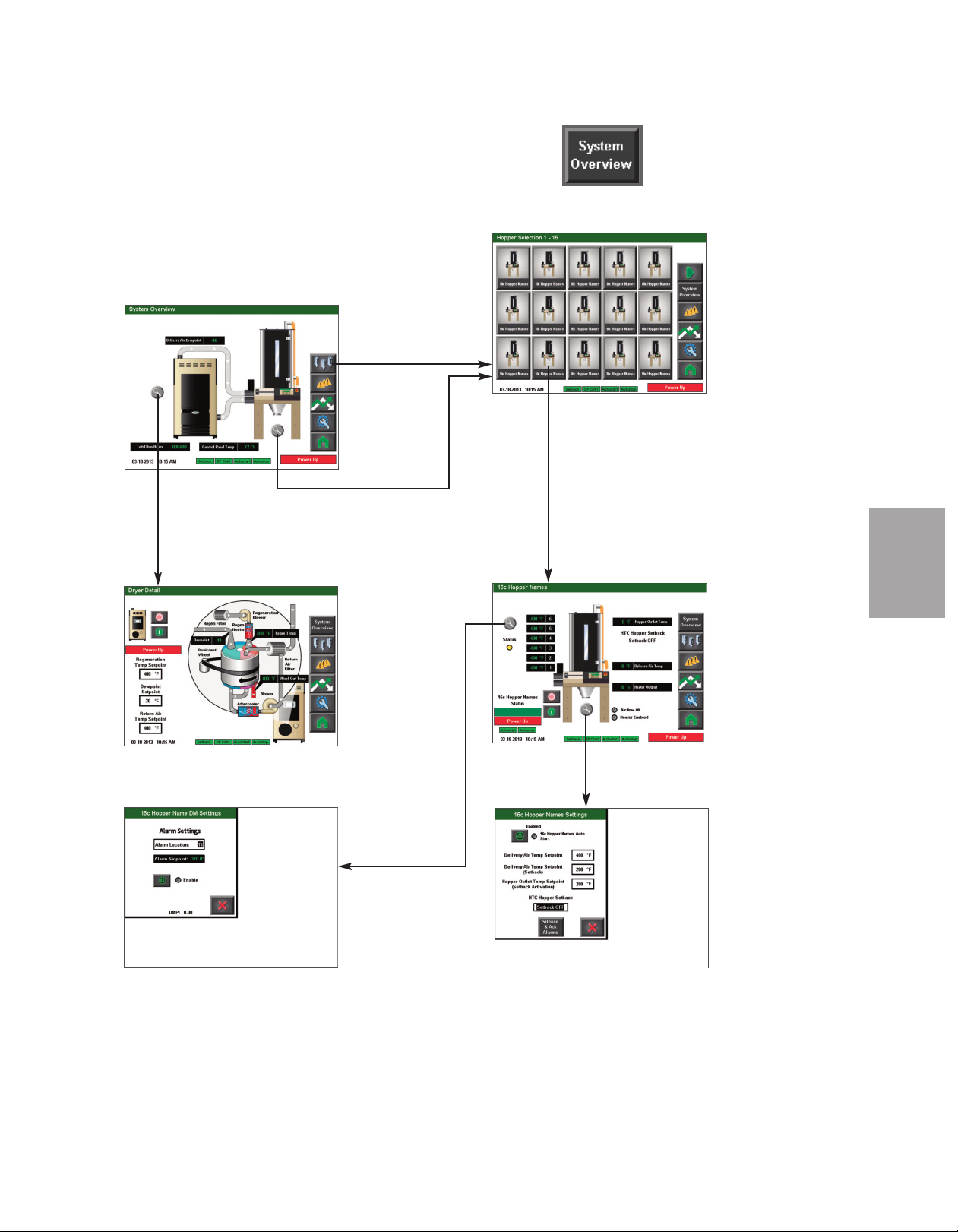
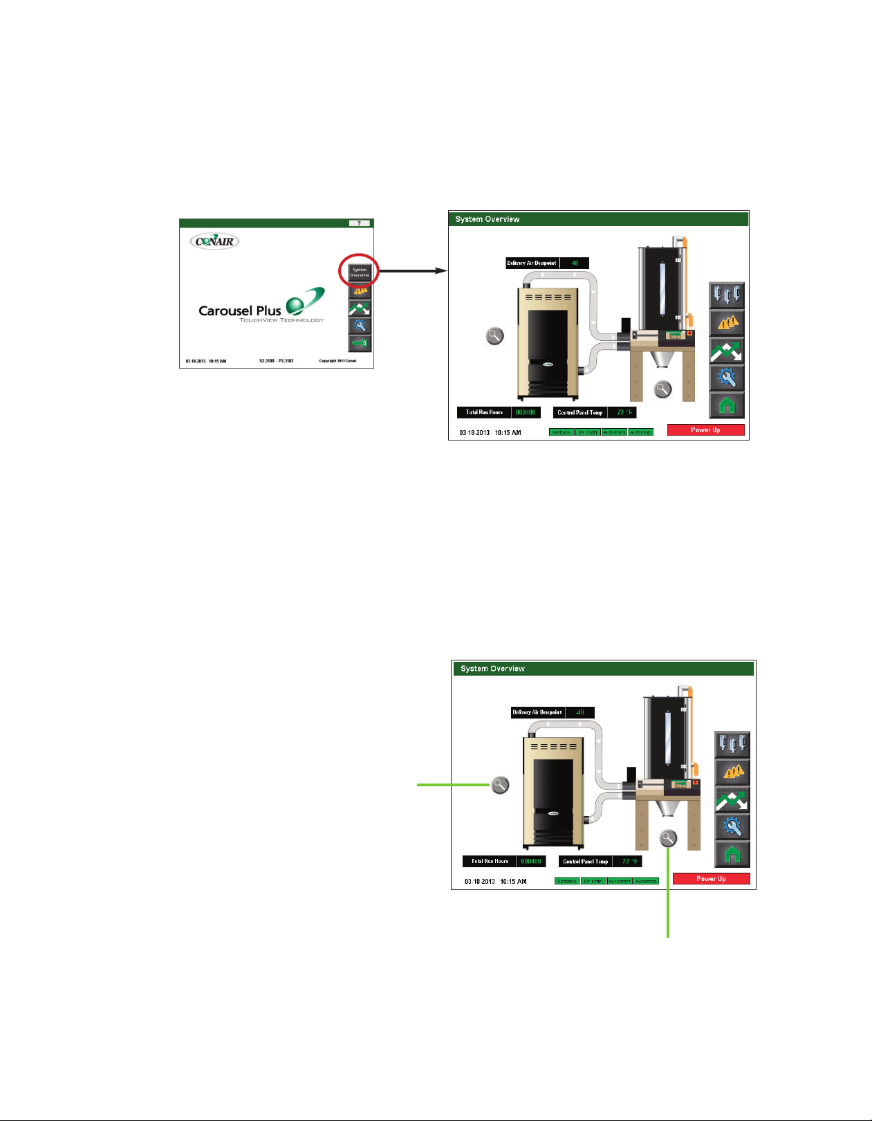
System Overview Screen
To access the System Overview Screen:
1 Press the System Overview button located on the home screen.
The System Overview screen provides the user with the current live information concerning
the delivery air dewpoint, the total run hours, and the control panel temperature.
This screen also allows the user to use the zoom buttons and select the dryer detail information or the hopper(s) detail information.
4 - 1 6 l O pe ra ti on
Dryer zoom
Hopper zoom
(continued)
Page 51
C o n t r o l F u nc t i o n D e s cr i p t i o ns - R W
C o n f i g ur a t i o n
System Overview Screen
To access the System Overview screen:
( c o nt i nu ed )
350
-40
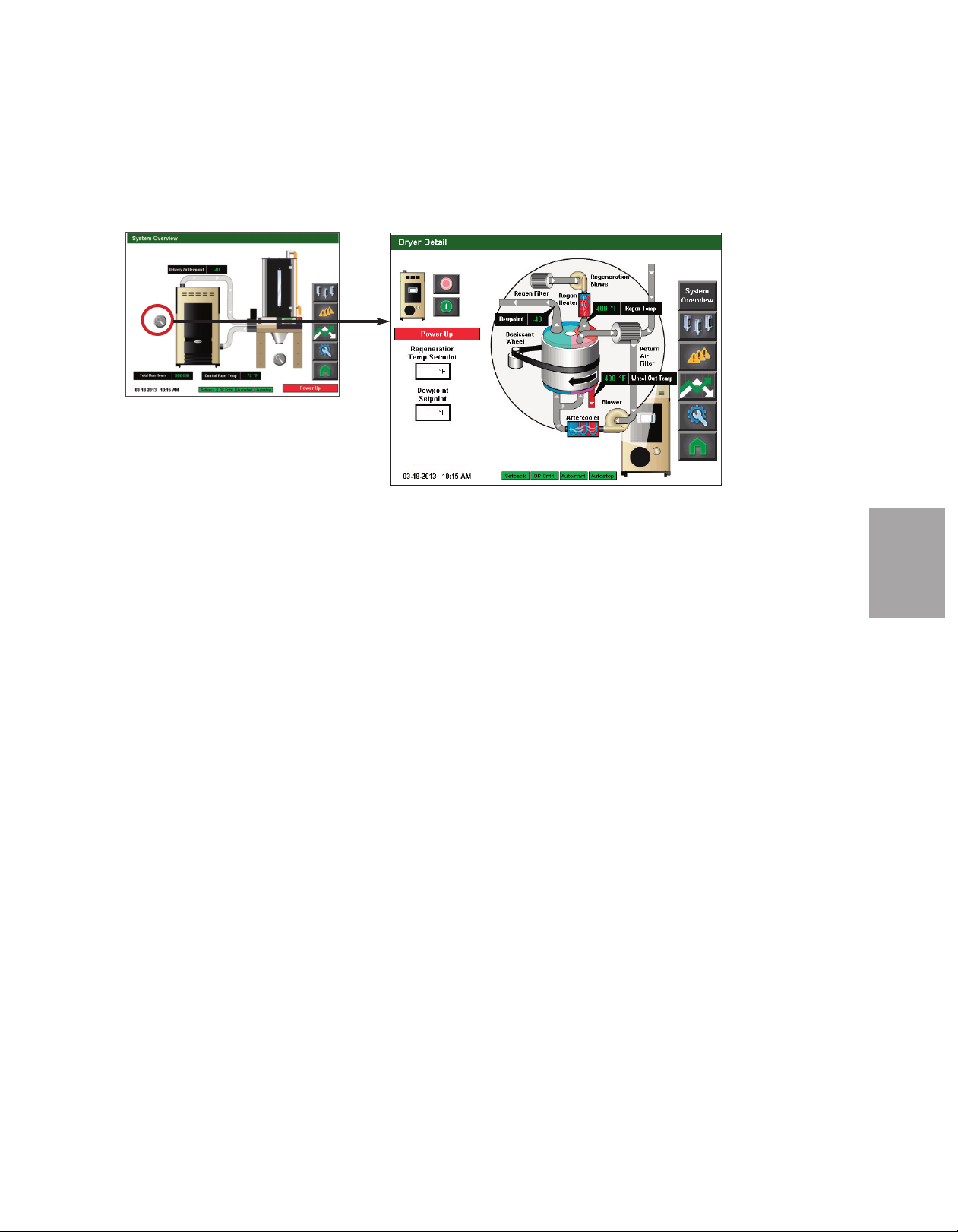
1 Press the Magnifying Glass (zoom) button associated with the dryer on the System
Overview screen.
O p era tio n
4
The System Overview screen provides the user with the current live information concerning
the processes within the dehumidifying dryer including:
• Regeneration Temperature (Regen. Temp)
• Return Air Temperature (Temp)
• Dewpoint
• Wheel Out Temperature (Temp)
It also tells the user the current status of the dryer blower (running or idle), as well as which
features (Autostart, Autostop, Setback, Dewpoint Control) are enabled.
If the user is logged-in at the proper security level, setpoint changes can be made to:
• Regeneration Temperature Setpoint - Conair recommends not changing this setting.
• Dewpoint Setpoint (optional)
This screen also allows the user to start or stop the dryer. The user can also view the other
system parameters, view alarms, view trending, view hopper settings, return to the System
Overview screen, or return to the Home screen by pressing the applicable buttons on the
right of the screen.
✐
NOTE: Live data is displayed as
colored text inside a solid black
box. Set points boxes are white
with heavy black borders. Set
points can be changed, if the user
has logged in at the proper security level, by pressing the set
point boxes. This will launch a
pop-up keypad window that can
be used to change the set point.
See Operation section entitled,
How to Navigate Control Screens.
After the new set point value has
been entered, press the "Enter"
key to lock in the new set point.
(continued)
O p e r at io n l 4 - 1 7
Page 52
C o n t r o l F u nc t i o n D e s cr i p t i o ns - R W
C o n f i g ur a t i o n ( c on ti nu e d)
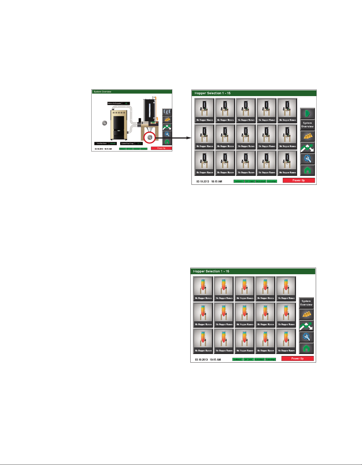
Hopper Selection Screen
To access the Hopper Selection screen:
1 Press the Magnifying Glass (zoom) button associated with the hopper on the System
Overview screen.
The Hopper Selection screen provides the user with the list of enabled hoppers. If the list is
empty, or does not show the proper number of hoppers, Setup has not been completed yet.
See Operation section entitled: Hopper Setup.
✐
NOTE: Depending on which options
your dryer has been configured
with, and whether or not you have
the DM3-e Drying Monitor enabled,
your screens and icons may appear
different. For example, if your
ResinWorks system is DM3-e
equipped, your hoppers will display
as Drying Monitor hoppers.
4 - 1 8 l O pe ra ti on
(continued)
Page 53

C o n t r o l F u nc t i o n D e s cr i p t i o ns - R W
C o n f i g ur a t i o n ( c on ti nu e d)
Individual Hopper Screen
Ready to Run
✐
NOTE: Depending on
which options your dryer
has been configured with,
and whether or not you
have the DM3-e Drying
Monitor enabled, your
screens and icons may be
different from what is
shown here. For example,
if your ResinWorks system
is DM3-e equipped, your
hoppers will display as
Drying Monitor hoppers (as
shown in these graphics).
To access the Individual Hopper screen:
1 Press the hopper button of the hopper you would like to view.
The Individual Hopper screen provides the user with the current live information concerning the processes within the hopper including:
• Current temperature in each of the six DM3-e sensor zones (if equipped).
• DM3-e status (if equipped).
• Hopper process heater status (if equipped).
• Hopper Outlet Temperature (Temp)
• Setback status (if equipped)
• Process Temperature
• Process Heater Output %
• Dryer Status
• Dryer features active (Setback, Dewpoint Control, Autostart, Autostop)
This screen allows the user to start or stop the hopper heater.
It also tells the user the current status of the dryer (running or idle), as well as which features (Autostart, Autostop, Setback, Dewpoint Control) are active.
If the user is logged-in at the proper security level, they can use the Magnifying Glass
(zoom) button near the tempeature zones to access DM3-e Settings, and the Magnifying
Glass (zoom) button near the bottom of the hopper to access the hopper setpoint settings.
The user can also view the other system parameters, view alarms, view trending, view hopper settings, return to the System Overview screen, or return to the Home screen by pressing
the applicable buttons on the right of the screen.
O p era tio n
4
✐
NOTE: See the Appendix of this
User Guide for more information
about using the DM3-e Drying
Monitor.
✐
NOTE: In addition to starting
and stopping the dryer, the Start
and Stop buttons indicate
whether the dryer can currently
be started or stopped. A faded
or not vibrant button indicates
that the dryer is not
ready/able to complete that function.
For example, a faded
Stop button indicates
the dryer is not ready
to stop.
(continued)
O p e r at io n l 4 - 1 9
Page 54
C o n t r o l F u nc t i o n D e s cr i p t i o ns - R W
✐
NOTE: Depending on which options
your dryer has been configured
with, and whether or not you have
the DM3-e Drying Monitor enabled,
your screens and icons may appear
different. For example, if your
ResinWorks system is DM3-e
equipped, your hoppers will display
as Drying Monitor hoppers.
✐
NOTE: Set points boxes are white
with heavy black borders. Set
points can be changed, if the user
has logged in at the proper security
level, by pressing the set point
boxes. This will launch a pop-up
keypad window that can be used to
change the set point.
section entitled, How to Navigate
the Control Screens.
set point value has been entered,
press the "Enter" key to lock in the
new set point.
See Operation
After the new
C o n f i g ur a t i o n
( c o nt i nu ed )
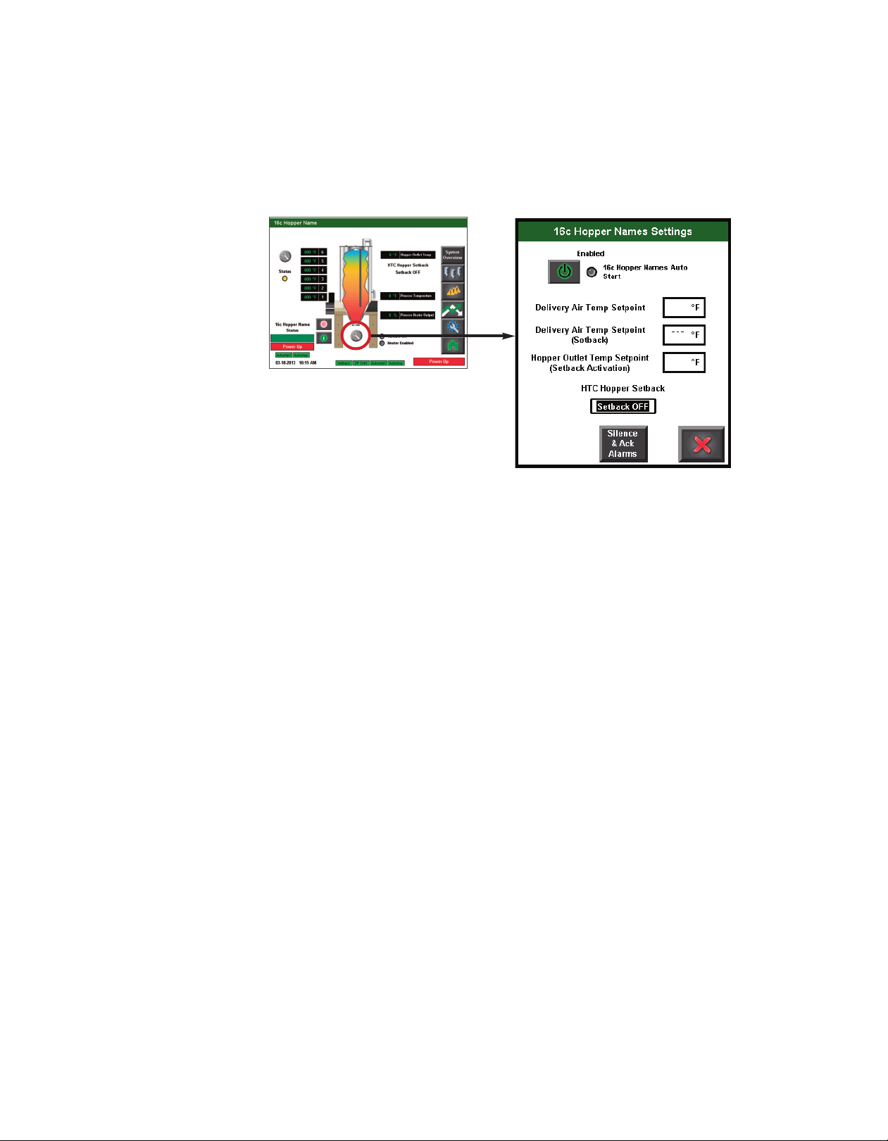
Hopper Setpoint Settings screen
350
Ready to Run
280
2
00
To access the Hopper Setpoint Settings screen:
1 Press the Magnifying Glass (zoom) button associated with the hopper on the
Individual Hopper screen.
The Hopper Settings Screen allows the user to establish the setpoints for the Delivery Air,
the Setback, the Hopper Outlet Temperature, and to enable/disable the Setback feature.
These setpoints can be adjusted for each hopper in your drying system (if equipped with
setback).
✐
NOTE: Setback must be inistalled and enabled at each HTC in a central drying system.
✐
NOTE: See the Appendix of this
User Guide for more information
about using the DM3-e Drying
Monitor.
4 - 2 0 l O pe ra ti on
Temperature Setback explained:
The purpose of Temperature Setback is to save on delilvery air heat (energy) and to minimize resin degradation due to overheating the material.
Temperature Setback works by monitoring the air temperature at the top of the hopper. The
setback features drops the delivery air temperature if the air temperature at the top of the
hopper gets too high. This saves energy and keeps the material from overheating.
✐
NOTE: High temperature at the top of the hopper could be the result of dried resin not leaving the hopper as it
should, or fresh resin not entering the hopper as it should. Check the conveying system to make sure that
material is entering and exiting the hopper when it should be.
(continued)
Page 55
C o n t r o l F u nc t i o n D e s cr i p t i o ns - R W
C o n f i g ur a t i o n
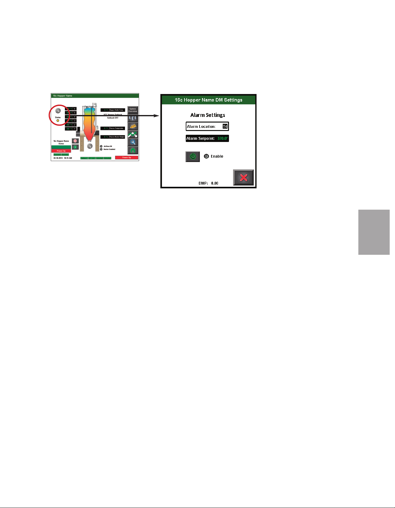
DM3-e Hopper Settings Screen (if equipped)
Ready to Run
To access the DM3-e Hopper Settings screen:
( c o nt i nu ed )
1 Press the Magnifying Glass (zoom) button associated with the Drying Monitor (beside
the temperature zones).
✐
NOTE: See the Appendix of this
User Guide for more information
about using the DM3-e Drying
Monitor.
✐
NOTE: The Drying Monitor
board version number is listed
on the bottom of this p op up
window. This information is
helpful for service and troubleshooting.
O p era tio n
4
The DM3-e Hopper Settings Screen provides the user with the current alarm location zone,
and the Alarm Setpoint, as well as a button to enable or disable DM3-e for this hopper.
These settings can be adjusted for each hopper in your DM3-e system.
(continued)
O p e r at io n l 4 - 2 1
Page 56
C o n t r o l F u nc t i o n D e s cr i p t i o ns - R W
✐
NOTE: Your DC-T control should
have been configured at the factory
for your ResinWorks system. These
settings should not need changed
unless your system changed, or the
control was replaced. Proper login
is required to change these settings.
C o n f i g ur a t i o n
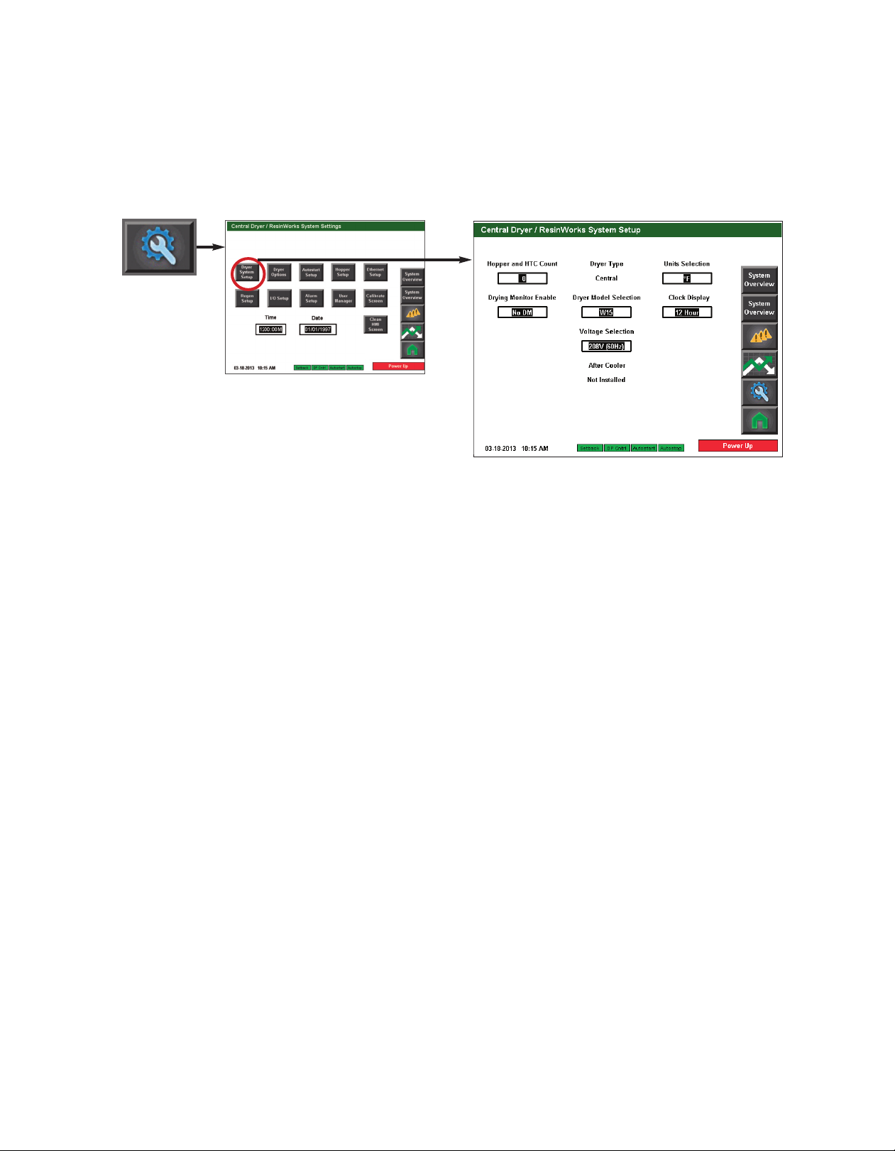
ResinWorks System Setup screen
To access the ResinWorks Setup screen:
( c o nt i nu ed )
1 Press the Settings button from the Home screen.
2 Press the ResinWorks Setup button.
✐
NOTE: See the Appendix of this
User Guide for more information
about using the DM3-e Drying
Monitor.
The ResinWorks System Setup screen provides the user with the ability to change the system settings of this ResinWorks system.
This screen allows you to change:
• Hopper and hopper heater count
• Units selection (Fahrenheit and Celsius)
• Drying Monitor (DM3-e) enabling
• Dryer model
• Clock display (12 hour and 24 hour)
• Voltage selection
4 - 2 2 l O pe ra ti on
(continued)
Page 57

C o n t r o l F u nc t i o n D e s cr i p t i o ns - R W
C o n f i g ur a t i o n
ResinWorks Dryer Options screen
To access the ResinWorks Dryer Options screen:
( c o nt i nu ed )
1 Press the Settings button from the Home screen.
2 Press the ResinWorks Dryer Options button.
The ResinWorks Dryer Options screen provides the user with the ability to enable or disable options.
O p era tio n
4
This screen allows you to change:
• Filter Check Monitor
• Dewpoint Monitor
• Dewpoint Control
• Regen Heater Current
✐
NOTE: Proper login is
required to change these
settings.
(continued)
O p e r at io n l 4 - 2 3
Page 58
✐
NOTE: Proper login is required to
change these settings.
C o n t r o l F u nc t i o n D e s cr i p t i o ns - R W
C o n f i g ur a t i o n ( c on ti nu e d)
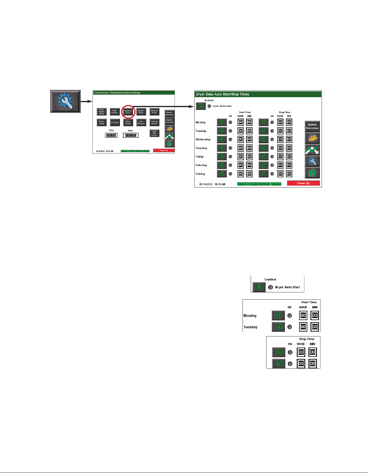
Autostart Setup screen
To access the ResinWorks Autostart screen:
1 Press the Settings button from the Home screen.
✐
NOTE: Autostart timer uses 24
hour time format. 00:00 is midnight. Note that this is a seven (7)
day repeating calendar, and not real
time.
2 Press the Autostart Setup button.
The ResinWorks Autostart Setup screen provides the user with the ability to enable or disable and set the start and stop time for dryer for each day of the week.
To setup Auto Start and Auto Stop:
1 Press the Enable button to enable Dryer Auto Start.
2 Press the Enable button next to each day of the
week you would like to set the Auto Start time.
3 Set the Auto Start time for each day you have
enabled.
4 Press the Enable button next to each day of the week you
would like to set the Auto Stop time.
5 Set the Auto Stop time for each day that you have enabled.
4 - 2 4 l Op er at io n
(continued)
Page 59
C o n t r o l F u nc t i o n D e s cr i p t i o ns - R W
C o n f i g ur a t i o n ( c on ti nu e d)
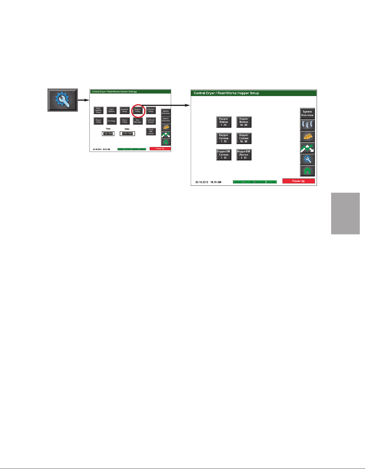
ResinWorks Hopper Setup screen
To access the ResinWorks Hopper Setup screen:
1 Press the Settings button from the Home screen.
2 Press the Hopper Setup button.
O p era tio n
4
The ResinWorks Hopper Setup screen provides the user with the ability to move to a screen
where you can:
• Customize hopper names
• Enable hopper heater communication
• Enable DM3-e communication (if equipped)
• Enable DM3-e alarms (if equipped)
✐
NOTE: Proper login is required to change these settings.
✐
NOTE: See the Appendix of this
User Guide for more information
about using the DM3-e Drying
Monitor.
(continued)
O p e r at io n l 4 - 2 5
Page 60

C o n t r o l F u nc t i o n D e s cr i p t i o ns - R W
✐
NOTE: Proper login is required to
change these settings.
C o n f i g ur a t i o n
Hopper Names screen
To access the Hopper Names screen:
( c o nt i nu ed )
1 Press the Settings button from the Home screen.
2 Press the Hopper Setup button.
✐
NOTE: Changing the hopper display
name does not change the order of
the hoppers. This order is based on
the hopper communications settings
and can not be changed.
✐
NOTE: Hopper names can be
changed multipe times as necessary. Conair recommends naming
the hopper using whatever system
works for your application. Some
users may choose to name hoppers
by material type or color; others
may choose to name hoppers
based on physical characteristics,
such as CH-54 Hopper.
3 Press the Hopper Names button.
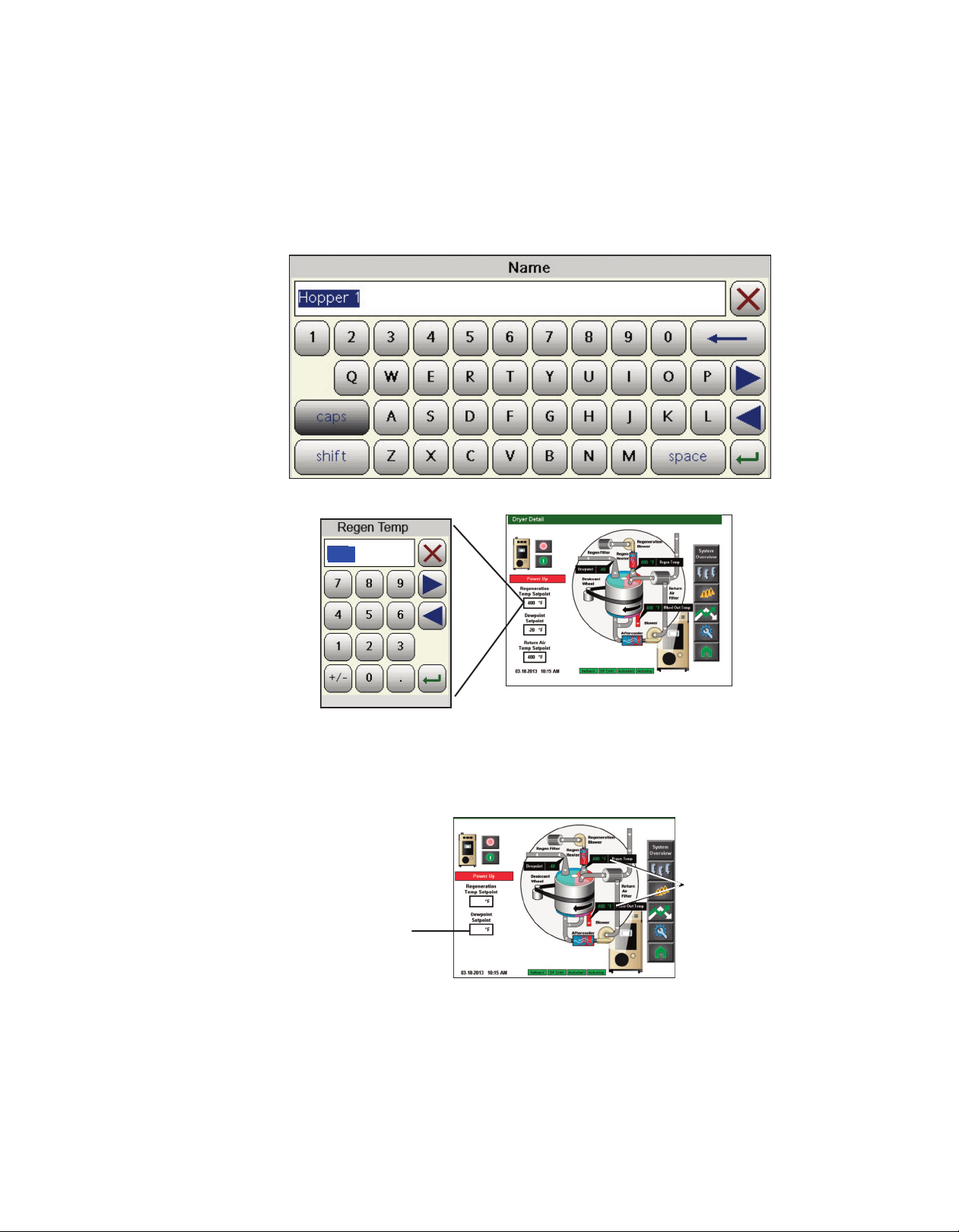
The Hopper Names screen provides the user with the ability to customize the name of any
hopper in the system. This name will be displayed as the hopper name on all future
screens.
To customize a hopper name:
1 Press the text inside the box of the hopper you would like to rename. All hoppers
are factory named “16c Hopper Name”. (This is simply a space holder for a user
entered hopper name up to 16 characters.)
2 Use the keypad to
enter your new hopper name. Hopper
names can be up to 16
characters in total
length.
3 Press the enter button
when complete.
4 Use steps 1 through 3
to change the name of
each hopper you
would like to customize.
4 - 2 6 l O pe ra ti on
(continued)
Page 61

C o n t r o l F u nc t i o n D e s cr i p t i o ns - R W
C o n f i g ur a t i o n ( c on ti nu e d)
Hopper Comms (Communications) screen
To access the Hopper Comms screen:
1 Press the Settings button from the Home screen.
2 Press the Hopper Setup button.
3 Press the Hopper Comms button.
The Hopper Comms screen provides the user with the ability to enable or disable communications to the hopper heater(s).
To enable communications to a hopper heater:
1 Press the Enable button beside the hopper heater you would
like to enable. The button will illuminate green. If
communications are successful, the LED beside the button will
change from grey to green.
2 Enable communications to any other hopper heaters you
would like to enable.
✐
NOTE: Proper login is
required to change
these settings.
O p era tio n
4
✐
NOTE: The ID # refers to the RS-485 Modbus ID address.
This number will never change. The text “16c Hopper
Names” will change to whatever name you change it to in
the hopper name screen.
Descriptions - RW Configuration, Hopper Names screen.
(continued)
See Operation: Control Function
O p e r at io n l 4 - 2 7
Page 62
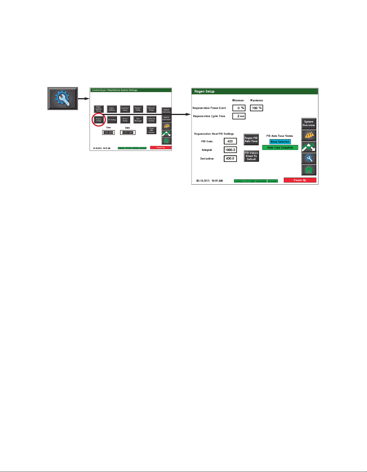
C o n t r o l F u nc t i o n D e s cr i p t i o ns - R W
✐
NOTE: Proper login is required to
change these settings.
C o n f i g ur a t i o n
Regen Setup screen
To access the Regen Setup screen:
( c o nt i nu ed )
1 Press the Settings button from the Home screen.
2 Press the Regen Setup button.
✐
NOTE: It is not typically necessary to use the Regen PID Auto Tune or the Reset PID Values to Factory button.
Contact the Conair Service department if you have questions about these items. Conair’s Instant Access 24/7
Parts and Service number is 800-458-1960. Outside the U.S., dial 814-437-6861.
4 - 2 8 l O pe ra ti on
(continued)
Page 63

C o n t r o l F u nc t i o n D e s cr i p t i o ns - R W
C o n f i g ur a t i o n
I/O Setup screen
To access the I/O Setup screen:
( c o nt i nu ed )
1 Press the Settings button from the Home screen.
2 Press the I/O Setup button.
The Dryer I/O Setup screen provides the user with the ability to open the Dewpoint Sensor
Setup, the Temp Sensor Setup, the Digital I/O Status or the Digital Output Test screen.
✐
NOTE: Proper login is
required to change
these settings.
O p era tio n
4
(continued)
O p e r at io n l 4 - 2 9
Page 64
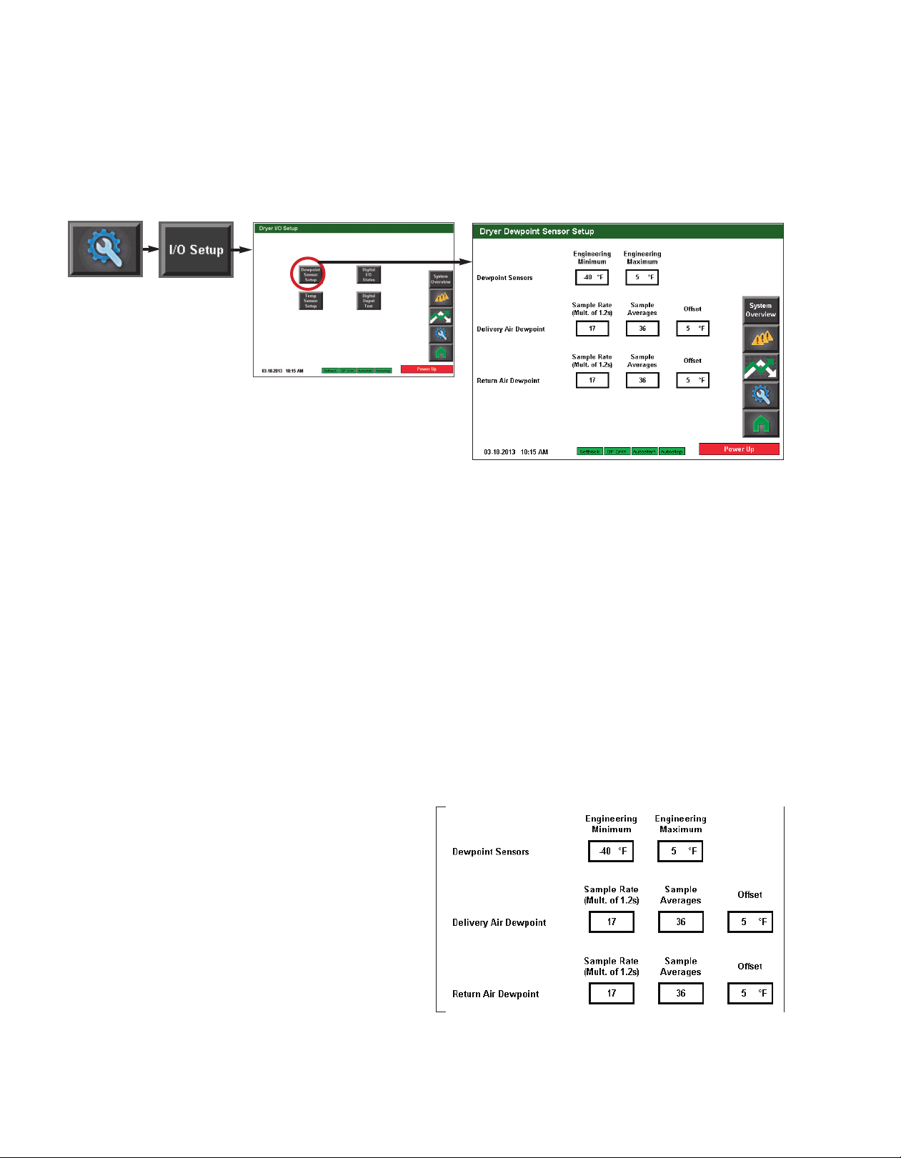
✐
NOTE: Proper login is required to
change these settings.
C o n t r o l F u nc t i o n D e s cr i p t i o ns - R W
C o n f i g ur a t i o n ( c on ti nu e d)
Dewpoint Setup screen
To access the Dryer Dewpoint Sensor Setup screen:
✐
NOTE: These are factory settings and
should not need changed. Consult
with Conair before making any
changes to these settings. Conair’s
Instant Access 24/7 Parts and Service
number is 800-458-1960. Outside
the U.S., dial 814-437-6861.
1 Press the Settings button from the Home screen.
2 Press the I/O Setup button.
3 Press the Dewpoint Setup button.
The Dryer Dewpoint Sensor Setup screen provides the user with the ability to adjust the settings for the Dewpoint sensors. This screen allows for adjustment of:
• Sensor minimum and maximum
• Delivery air dewpoint sample rate, sample averages, and offset
• Return air dewpoint sample rate, sample averages, and offset
To change a setpoint:
1 Press the text inside
white box with thick
black outline of the setting you would like to
change.
4 - 3 0 l O pe ra ti on
2 Use the keypad to enter
the new setting. Setting
range will be displayed
at the bottom of the pop
up keypad.
3 Press the enter key.
(continued)
Page 65

C o n t r o l F u nc t i o n D e s cr i p t i o ns - R W
C o n f i g ur a t i o n
Digital I/O Status screen
To access the I/O Status screen:
( c o nt i nu ed )
1 Press the Settings button from the Home screen.
2 Press the I/O Setupbutton.
3 Press the I/O Status button.
The I/O Status screen allows for a visual display of active outputs attached to the DC-T
control. Inputs or outputs that are active will turn green. Inactive inputs and outputs will
appear grey.
✐
NOTE: Proper login is
required to test the outputs. Depending on the
configuration of your
dryer, some inputs and
outputs may not be available.
O p era tio n
4
(continued)
O p e r at io n l 4 - 3 1
Page 66
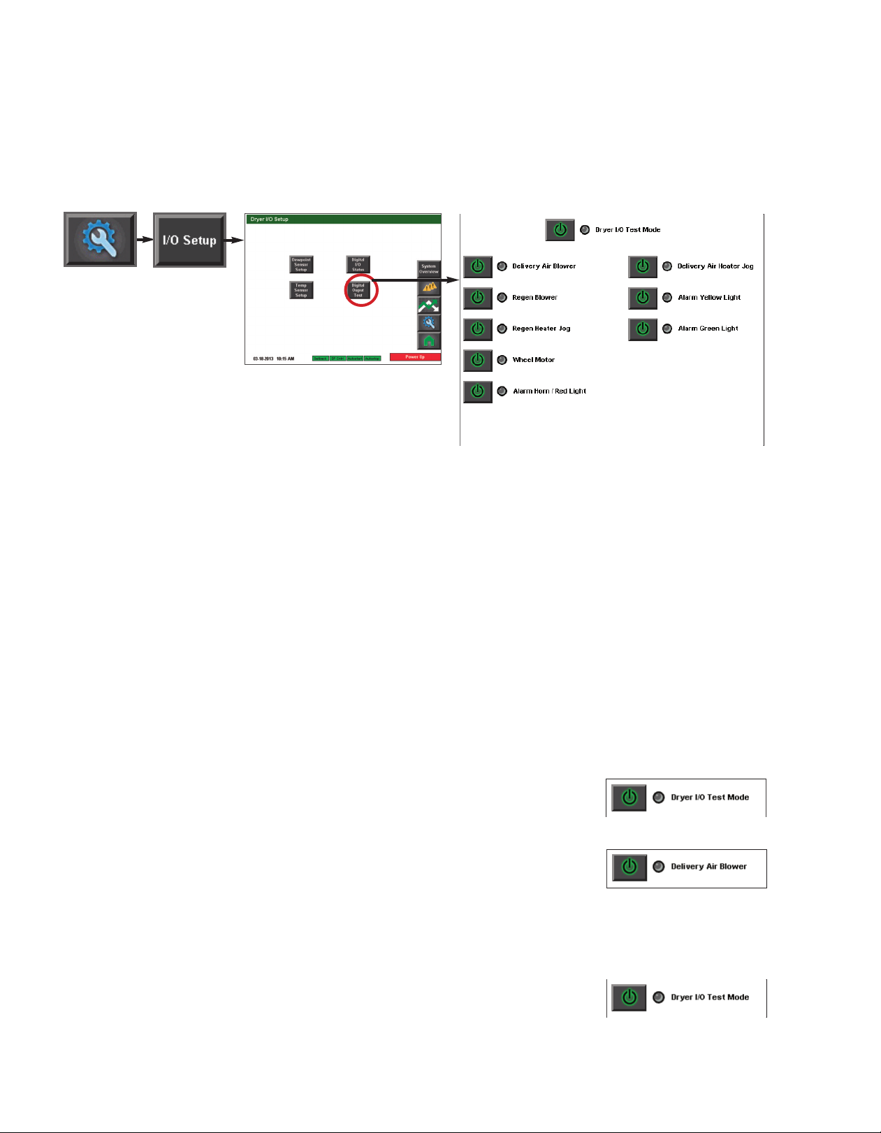
C o n t r o l F u nc t i o n D e s cr i p t i o ns - R W
✐
NOTE: The dryer must be
stopped in order to perform the
test mode.
✐
NOTE: Proper login is required
to test the outputs. Depending
on the configuration of your
dryer, some inputs and outputs
may not be available.
C o n f i g ur a t i o n
Digital Output Test screen
To access the Test screen:
( c o nt i nu ed )
1 Press the Settings button
from the Home screen.
2 Press the I/O Setup button.
3 Press the Digital Output Test button.
The test screen allows for digital output tests of various outputs attached to the DC-T control. This screen allows for testing of:
✐
NOTE: On intial test, the delivery air blower will start automatically. This is not unusual
and should be expected.
• Delivery air blower
• Regen blower
• Regen heater (jog)
• Wheel motor
• Alarm horn/red light
• Heater isolation contactor
• Delivery air heater (jog)
• Alarm yellow light
• Alarm green light
To test an output:
1 Press the power button to enable the Dryer I/O Test
Mode. The button should illuminate and the LED beside
the button should change from grey to green indicating that test mode is enabled.
2 Press the power button beside the output you would
like to test. The button should illuminate and the LED
beside the button should change from grey to green indicating power has been sent to the output.
3 Press the power button beside the output again to stop the test. Note that some tests
are a jog test and will not require pressing the button again to stop. Jog tests are programmed to run for three (3) seconds.
4 - 3 2 l O pe ra ti on
4 Press the power button beside the Dryer I/O Test
Mode text to disable test mode.
(continued)
Page 67
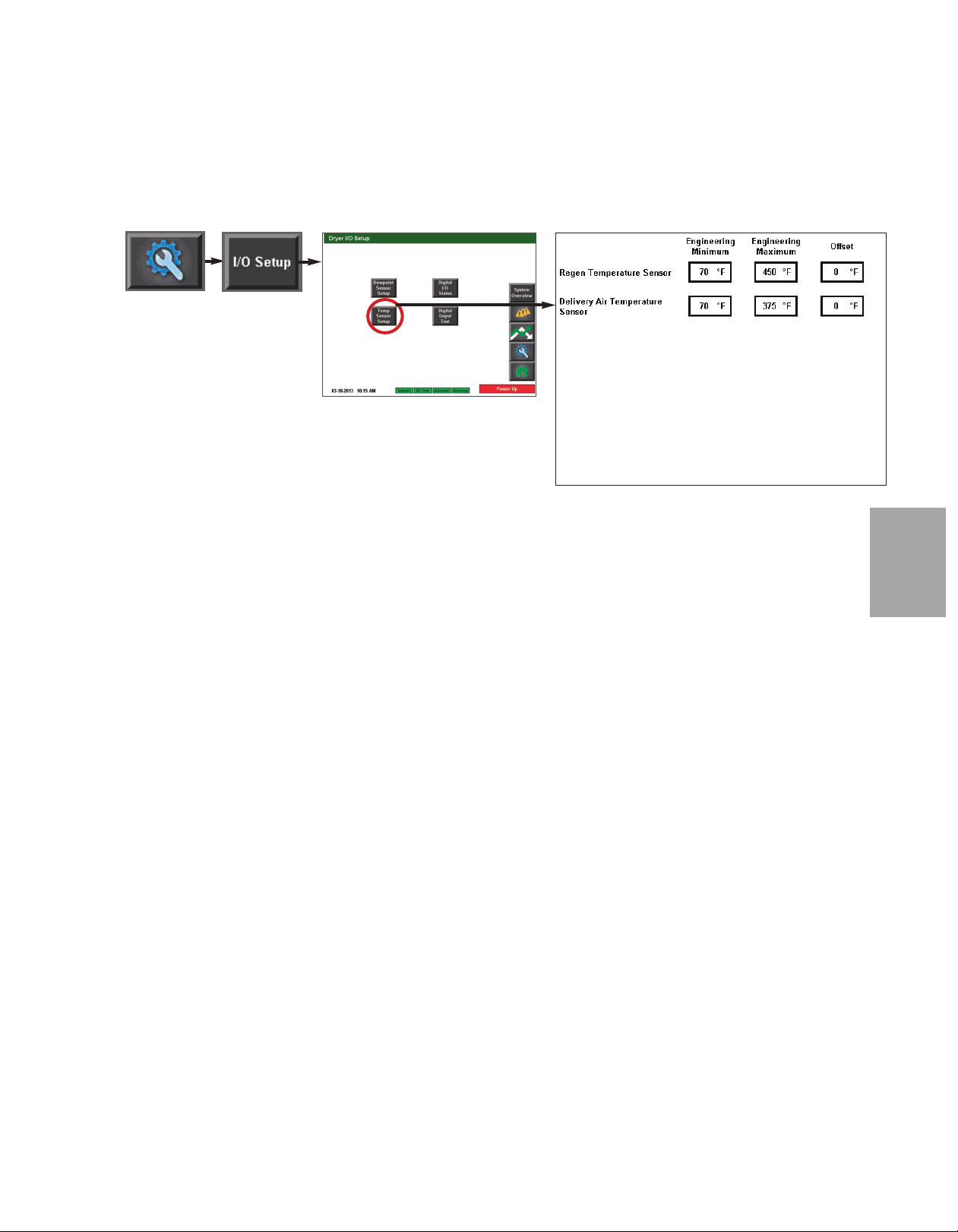
C o n t r o l F u nc t i o n D e s cr i p t i o ns - R W
C o n f i g ur a t i o n ( c on ti nu e d)
Temperature Sensor Setup screen
To access the Temperature
Sensor Setup screen:
1 Press the Settings button
from the Home screen.
2 Press the I/O Setup button.
3 Press the Temperature Sensor Setup button.
The test screen allows the user to set the setpoints for the Temperature Sensors:
• Regen Temperature Sensor
O p era tio n
4
To change a setting:
1 Press the white outlined setpoint box. A pop up number pad will appear.
2 Enter the desired setting. Press enter after you have entered the numbers.
3 Repeat steps 1 and 2 for all settings you would like to adjust. Note that depending
on your dryer configuration and your enabled options, your screen may appear different
than what is shown here.
✐
NOTE: Proper login is
required to change these
settings.
(continued)
O p e r at io n l 4 - 3 3
Page 68
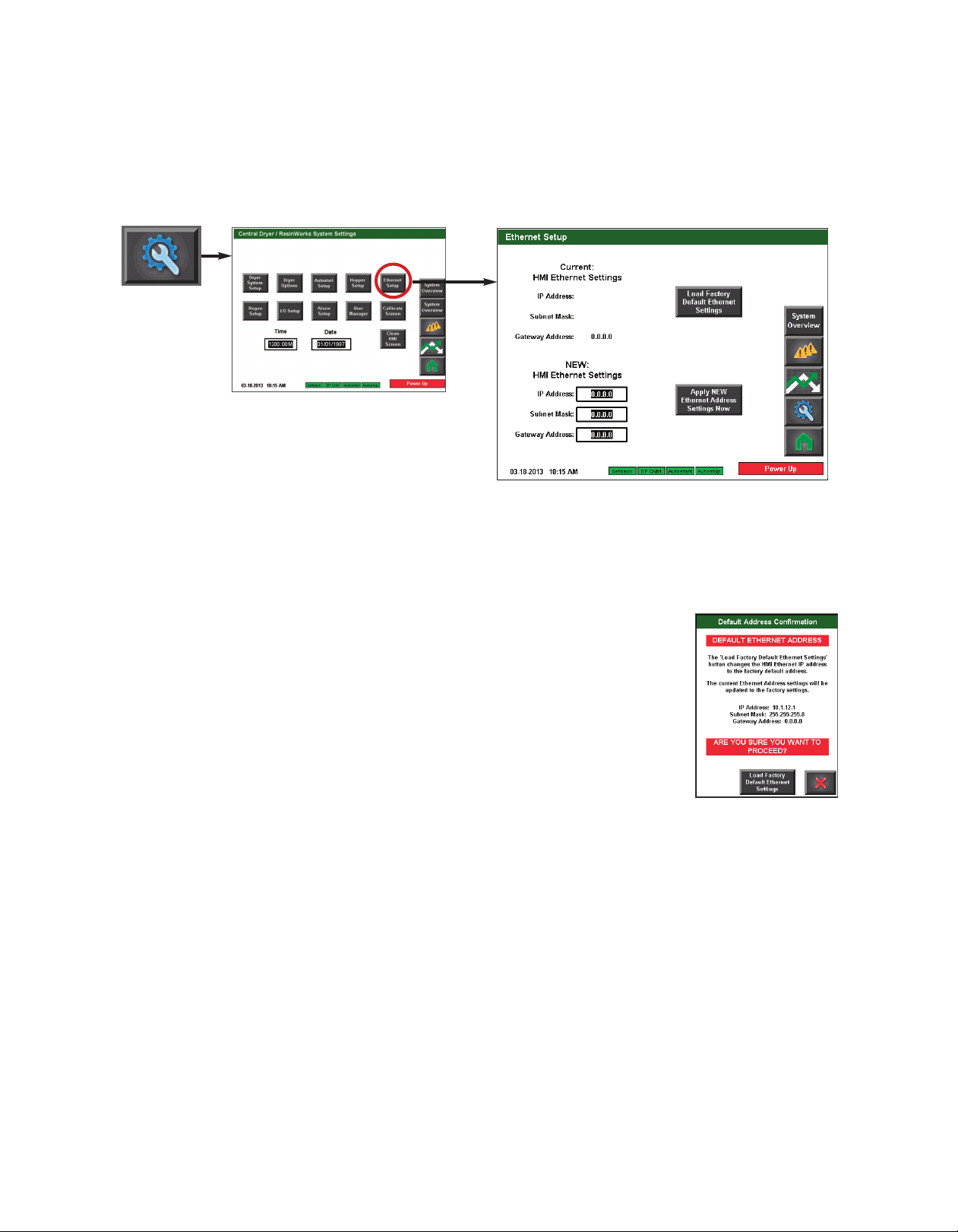
✐
NOTE: Proper login is required to
change these settings.
C o n t r o l F u nc t i o n D e s cr i p t i o ns - R W
C o n f i g ur a t i o n ( c on ti nu e d)
Ethernet Setup screen
To access the Ethernet Setup
screen:
1 Press the Settings button
from the Home screen.
2 Press the Ethernet Setup button.
The Ethernet Setup screen provides the user with the ability to view current HMI Ethernet
settings, load factory default Ethernet settings, or to change and apply new Ethernet settings.
To load the factory default Ethernet settings:
1 Press the Load Factory Default Ethernet Settings button.
2 Press the button to confirm that you want to load the factory
default settings. Press the X button if you want to exit without
loading the default factory settings.
✐
NOTE: The default IP
address established by
Conair is 10.1.12.1
4 - 3 4 l O pe ra ti on
(continued)
Page 69
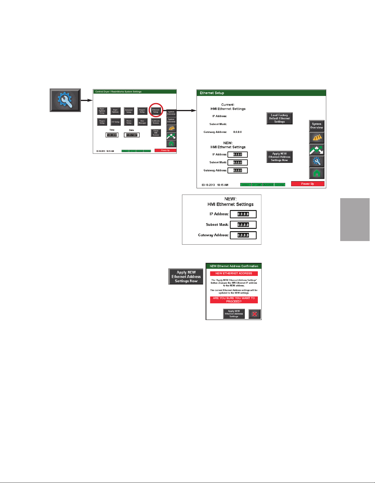
C o n t r o l F u nc t i o n D e s cr i p t i o ns - R W
C o n f i g ur a t i o n ( c on ti nu e d)
Ethernet Setup screen
To apply new Ethernet settings:
1 Enter the new settings in the white boxes with
thick black borders. When you touch the setting
inside the box, a pop up number pad will appear.
2 Use the number pad to enter the new setting.
Press the enter button on the number pad to enter the
new setting.
3 Repeat steps 1 and 2 for each address setting.
4 Press the Apply NEW Ethernet Address
Settings Now button.
5 Press the button to confirm that you want to apply the new
settings. Press the X button if you want to exit without applying the new settings.
O p era tio n
4
✐
NOTE: Proper login is required to
change these settings.
(continued)
O p e r at io n l 4 - 3 5
Page 70
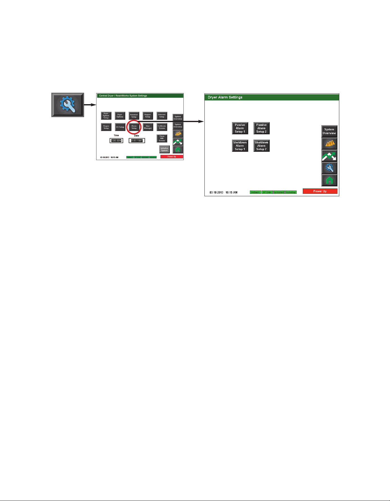
C o n t r o l F u nc t i o n D e s cr i p t i o ns - R W
✐
NOTE: Proper login is required to
change these settings.
C o n f i g ur a t i o n
Alarm Setup screen
To access the Alarm Setup screen:
( c o nt i nu ed )
1 Press the Settings button from the Home screen.
2 Press the Alarm Setup button.
The Alarm Setup screen provides the user with the ability to enable, disable and adjust setpoints for alarms in the ResinWorks system. Both passive and shutdown alarms can be
modified from these screens.
4 - 3 6 l O pe ra ti on
(continued)
Page 71
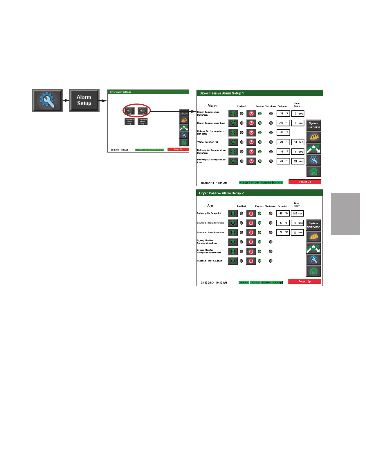
C o n t r o l F u nc t i o n D e s cr i p t i o ns - R W
C o n f i g ur a t i o n
Passive Alarm Setup (1 & 2)
To access the Passive Alarm Setup screens:
( c o nt i nu ed )
1 Press the Settings button from the Home screen.
2 Press the Alarm Setup button.
3 Press the Passive Alarm Setup button for the Passive
alarms you would like to configure (screen 1 or screen 2 - if
applicable).
4 Enter the desired setpoint and delay (if applicable) for
each alarm.
O p era tio n
4
✐
NOTE: Some alarms require the user to enable the alarm, and to choose
between Passive or Shutdown alarm type. The first “power” button
enables or disables the alarm. The second button chooses between
Passive or Shutdown alarm.
✐
NOTE: Proper login is required to modify alarm settings. Depending on
your dryer configuration, your alarm choices and screen configurations
may vary from what is shown in this User Guide.
IMPORTANT: Factory
default alarm setpoints
should not be changed
without first consulting
with Conair.
Conair’s Instant Access
24/7 Parts and Service
number is
800-458-1960.
Outside the U.S., dial
814-437-6861.
(continued)
O p e r at io n l 4 - 3 7
Page 72
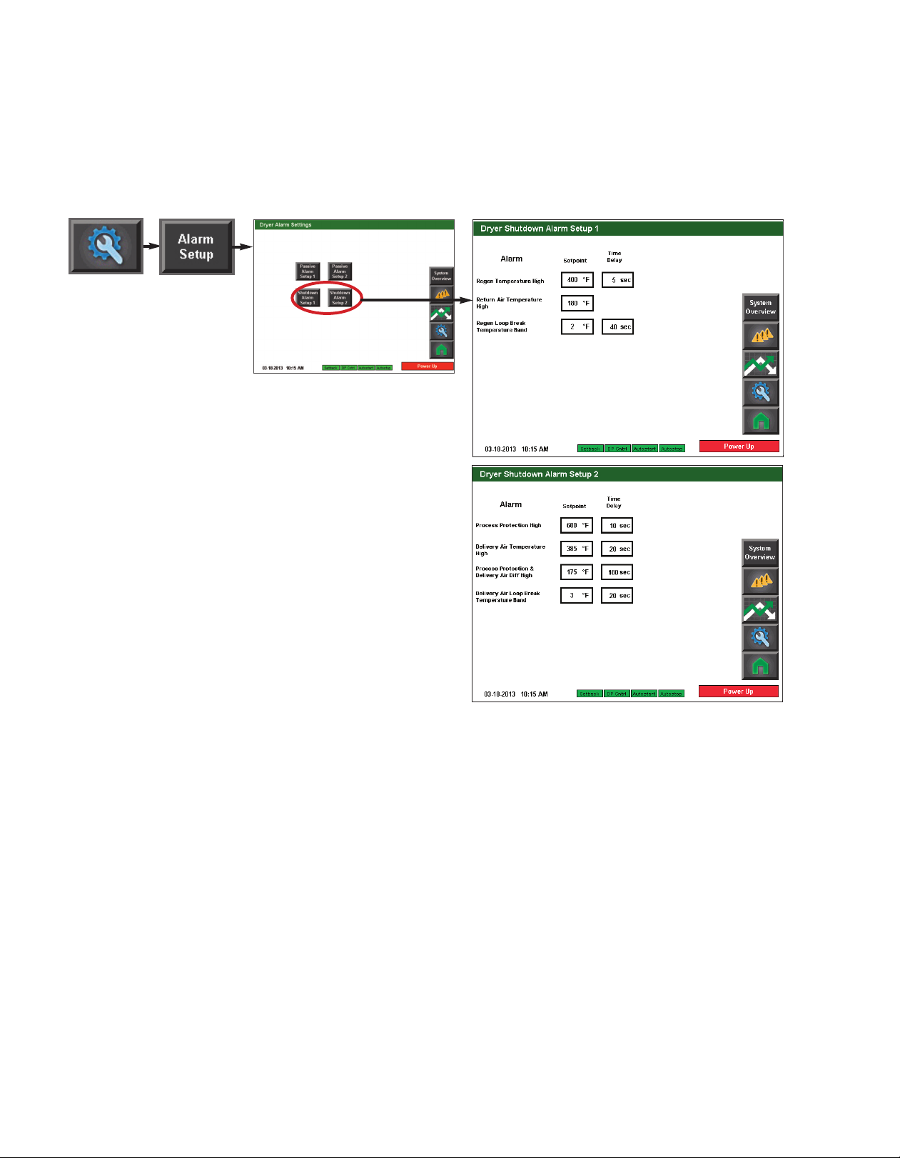
C o n t r o l F u nc t i o n D e s cr i p t i o ns - R W
C o n f i g ur a t i o n ( c on ti nu e d)
Shutdown Alarm Setup (1 & 2)
To access the Shutdown Alarm
Setup screens:
✐
NOTE: Proper login is required
to modify alarm settings.
IMPORTANT: Factory
default alarm setpoints
should not be changed
without first consulting
with Conair.
Conair’s Instant Access
24/7 Parts and Service
number is
800-458-1960.
Outside the U.S., dial
814-437-6861.
1 Press the Settings button from
the Home screen.
2 Press the Alarm Setup button.
3 Press the Shutdown Alarm
Setup button for the Shutdown
alarms you would like to configure (screen 1 or screen 2 - if
applicable).
4 Enter the desired setpoint
and delay for each shutdown
alarm.
4 - 3 8 l O pe ra ti on
(continued)
Page 73
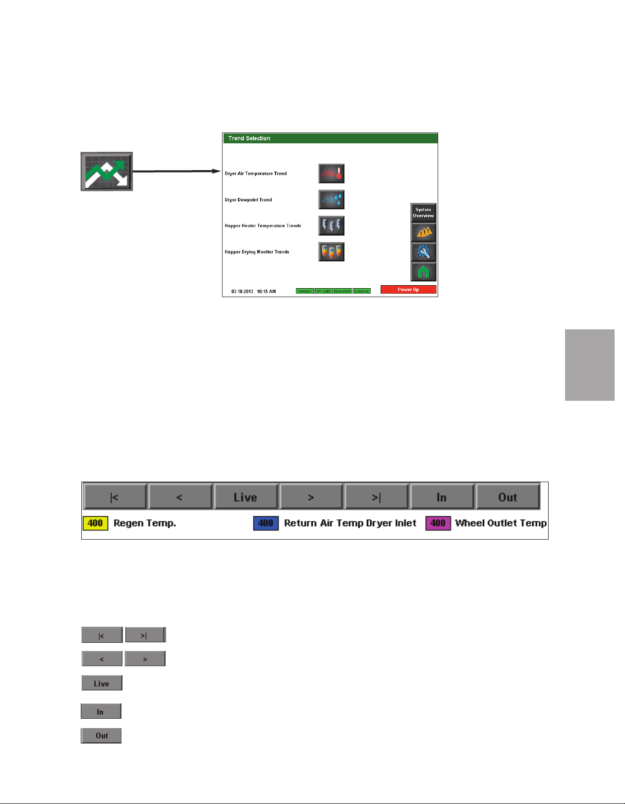
C o n t r o l F u nc t i o n D e s cr i p t i o ns - R W
C o n f i g ur a t i o n
Trending
To access the Trending screens:
( c o nt i nu ed )
1 Press the Trending button from the Home screen.
The Trend Selection screen allows you to choose which trending screens you would like to
view. From this screen, you can choose to view:
• Dryer Air Temperature Trend
• Dryer Dewpoint Trend
• Hopper Heater Temperature Trends
• Hopper Drying Monitor Trends (if equipped)
✐
NOTE: Depending on your DC-T
configuration, and system security, different users may not be
able to access the trending
screens. Also, if you do not have
DM3-e enabled, or the Drying
Monitor equipment at your drying
hoppers, you will not be able to
view Drying Monitor Trends.
O p era tio n
4
Trending Screen Navigation
Each trending screen will allow the user to scroll through data. When the screen first
opens, it will be displaying a two (2) hour window, and will have saved the data for the last
seven (7) day period. The scroll buttons near the bottom of the screen allow the user to
scroll back to an earlier time or forward to the present time, or jump immediately to live
data. The user can also touch any point on the trend line and the display will show the data
reading, date, and time for that spot in the trend.
Scroll to the beginning or end of the record.
Scroll back or forward one point at a time (30 seconds).
Move to live data.
Zoom in (Instead of seeing 2 hours of trend in the window, you will see 1 hour,
30 minutes, 15 minutes, etc.)
Zoom out (Instead of seeing 2 hours of trend in the window, you will see 3
hours, 4 hours, 5 hours, etc.)
(continued)
✒
TIP: A dashed line or a
break in the trend line
represents a time where
power to the dryer was
off (either due to shut-
down or to power outage).
O p e r at io n l 4 - 3 9
Page 74

C o n t r o l F u nc t i o n D e s cr i p t i o ns - R W
✐
NOTE: Using the scroll
backward and scroll foward
arrows will move the line 30
seconds at a time.
C o n f i g ur a t i o n
Dry Air Temperature Trend
To access the Dry Air Temperature
Trend screen:
( c o nt i nu ed )
1 Press the Trending button
from the Home screen.
2 Press the Dryer Air
Temperature Trend button.
The Dryer Air Temperature Trending screen allows the user to view the air temperature
trend vs. time at several locations in the Carousel Plus Dryer. The air temperature reading
locations are denoted by various colors. The colors associated with the locations are:
Yellow: Regeneration Temperature (within the dryer)
Blue: Return Air Dryer Inlet Temperature
Purple: Wheel Outlet Temperature
The Dryer Air Temperature Trending screen shows a snap shot of the last two (2) hours of
operation and records and saves trending data for the last seven (7) day period. The scroll
buttons near the bottom of the screen allow the user to scroll back to an earlier time or forward to the present time, plus jump to the present (Live) time from any time within the
trending record.
✐
NOTE: See Trending Screen Navigation (Operation Section: Control Function Descriptions- RW
Configuration: Trending) for more information on how use the navigation buttons to navigate through individual trending screens.
4 - 4 0 l O pe ra ti on
(continued)
Page 75
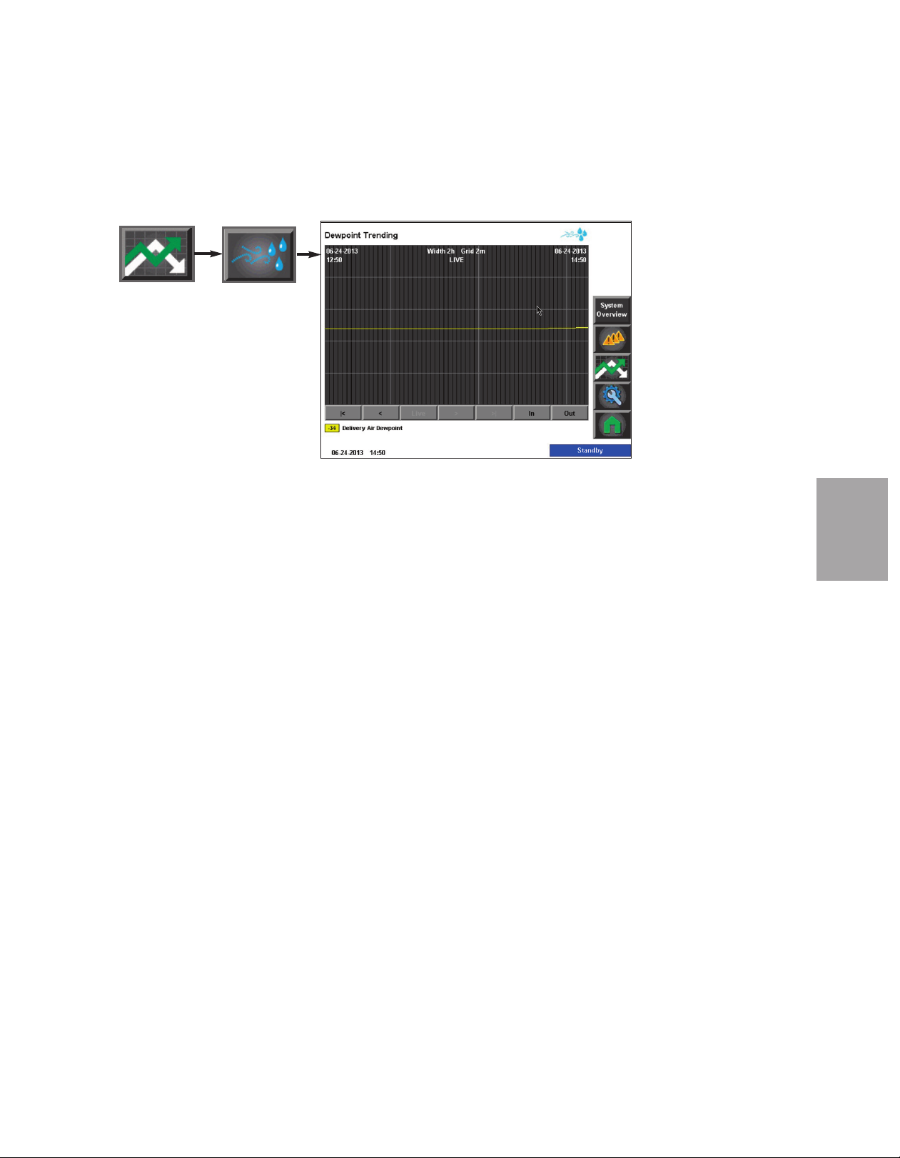
C o n t r o l F u nc t i o n D e s cr i p t i o ns - R W
C o n f i g ur a t i o n
Dryer Dewpoint Trend
To access the Dryer Dewpoint
Trend screen:
( c o nt i nu ed )
1 Press the Trending button
from the Home screen.
2 Press the Dryer Dewpoint
Trend button.
The Dewpoint Trending screen allows the user to view the dewpoint trend vs. time in the
Carousel Plus Dryer.
The Dewpoint Trending screen shows a snap shot of the last two (2) hours of operation and
records and saves trending data for the last seven (7) day period. The scroll buttons near the
bottom of the screen allow the user to scroll back to an earlier time or forward to the present time, plus jump to the present (Live) time from any time within the trending record.
✐
NOTE: Using the scroll
backward and scroll foward
arrows will move the line 30
seconds at a time.
O p era tio n
4
✐
NOTE: See Trending Screen Navigation (Operation Section: Control Function Descriptions- RW
Configuration: Trending) for more information on how use the navigation buttons to navigate through individual trending screens.
(continued)
O p e r at io n l 4 - 4 1
Page 76

✐
NOTE: Using the scroll
backward and scroll foward
arrows will move the line 30
seconds at a time.
C o n t r o l F u nc t i o n D e s cr i p t i o ns - R W
C o n f i g ur a t i o n ( c on ti nu e d)
Hopper Heater Temperature Trends
To access the Hopper Heater Temperature Trends screen:
1 Press the Trending button from the Home screen.
2 Press the Hopper Heater Temperature Trend button.
3 Press the Hopper trend you would like to view.
The Hopper Heater Temperature Trending screen allows the user to view the air temperature trend vs. time in two locations related to the hopper. The temperature reading locations
are denoted by various colors. The colors associated with the locations are:
Yellow: Hopper Delivery Air Temperature
Blue: Hopper Outlet Temperature (if equipped with setback)
The Hopper Heater Temperature Trending screen shows a snap shot of the last two (2)
hours of operation and records and saves trending data for the last seven (7) day period.
The scroll buttons near the bottom of the screen allow the user to scroll back to an earlier
time or forward to the present time, plus jump to the present (Live) time from any time
within the trending record.
✐
NOTE: See Trending Screen Navigation (Operation Section: Control Function Descriptions- RW
Configuration: Trending) for more information on how use the navigation buttons to navigate through individual trending screens.
4 - 4 2 l O pe ra ti on
(continued)
Page 77
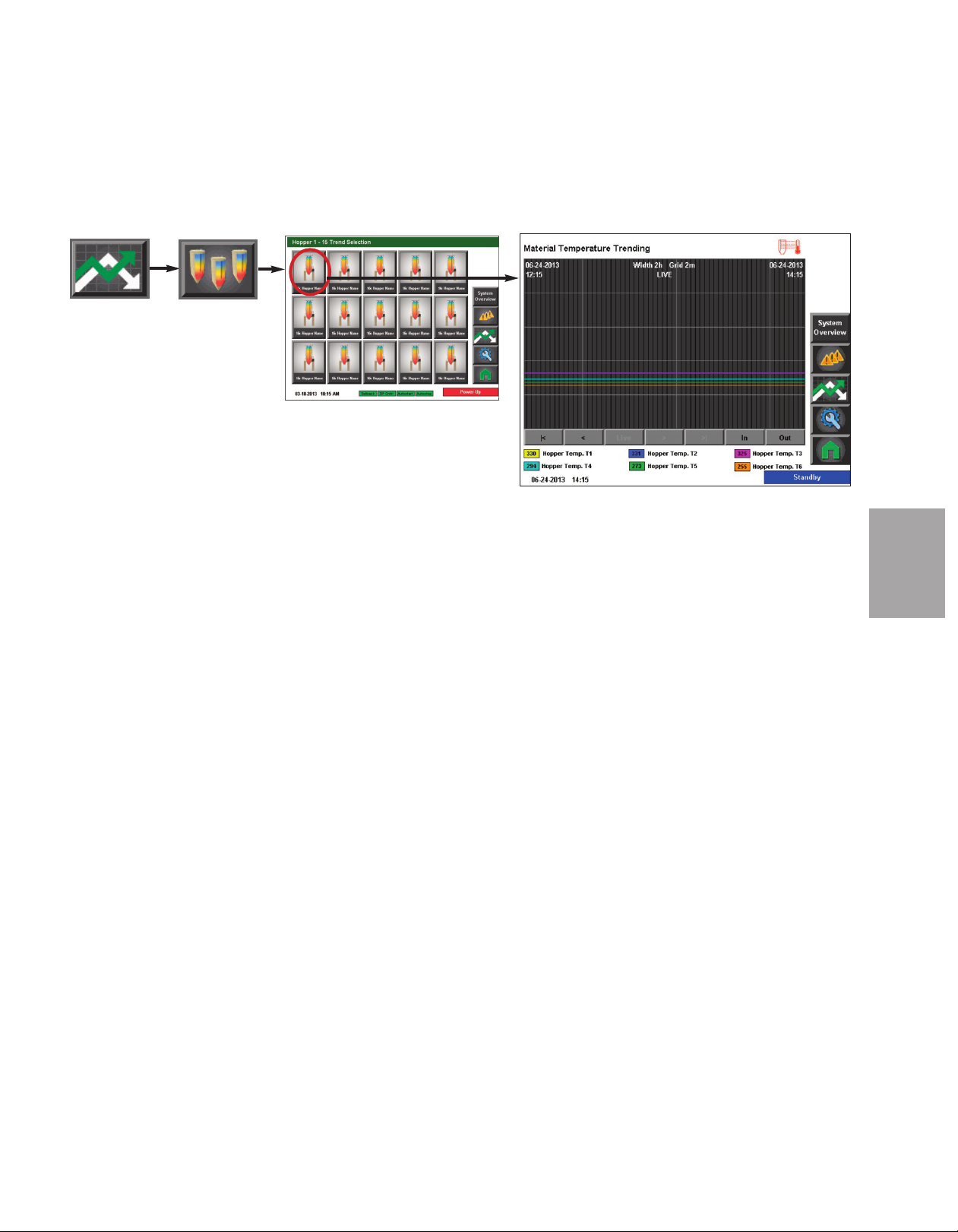
C o n t r o l F u nc t i o n D e s cr i p t i o ns - R W
C o n f i g ur a t i o n ( c on ti nu e d)
Hopper Drying Monitor Trends (if equipped)
To access the Hopper
Drying Monitor Trend
screen:
1 Press the Trending button from the Home screen.
2 Press the Hopper Trend button.
3 Select the individual hopper you want to see trending for.
The Hopper Drying Monitor Trending screen allows the user to view the temperatures at
each of the six (6) temperature zones of the DM3-e probe.
The DM3-e Trending screen shows a snap shot of the last two (2) hours of operation and
records and saves trending data for the last seven (7) day period. The scroll buttons near the
bottom of the screen allow the user to scroll back to an earlier time or forward to the present time, plus jump to the present (Live) time from any time within the trending record.
✐
NOTE: See Trending Screen Navigation (Operation Section: Control Function Descriptions- RW Configuration:
Trending) for more information on how use the navigation buttons to navigate through individual trending
screens.
✐
NOTE: Using the scroll
backward and scroll foward
arrows will move the line 30
seconds at a time.
✐
NOTE: See the DM3-e User
Guide for more information
about using the DM3-e Drying
Monitor.
O p era tio n
4
(continued)
O p e r at io n l 4 - 4 3
Page 78

C o n t r o l F u nc t i o n D e s cr i p t i o ns - R W
C o n f i g ur a t i o n ( c on ti nu e d)
Alarms
When an alarm occurs, an audible
sound will be triggered and the
operator interface will display a
flashing alarm message.
To view an alarm from any opera-
tor screen, press the Alarm button.
1 Press the Alarms button.
2 View the current alarms.
3 Decide if you want to Acknowledge Alarms, Silence and Acknowledge Alarms,
Reset All Alarms or clear individual alarms.
The following buttons are available from the Alarms log screen:
Previous - The previous button is used to select the previous alarm when
multiple alarms are displayed.
Next - The next button is used to select the next alarm when multiple alarms
are displayed.
Alarm History- Pressing the Alarm
History button will show a detailed
listof the alarm history.
Acknowledge All - The acknowledge all
button is used to acknowledge all the
alarms on the list.
Reset All Alarms - The Reset button is used to clear all alarms on the list. If the
condition has not been remedied, the alarm will reappear.
4 - 4 4 l O pe ra ti on
Page 79

O p
e rat
i o n
- St
C o nfigura t i o n
a n
A l o n
d
e D r ye r
O p era tio n
4
creen flow
The follow
the operation of the dryer w
deli
ing pages
very air heat) attached to a s
(s
s
,
charts
hen factory conf
ingle hopper
creen des
igured as
and bas
criptions
,
tand alone dryer (providing internal
a s
ic operation) des
cribe
O p e r at io n l 4 - 4 5
Page 80
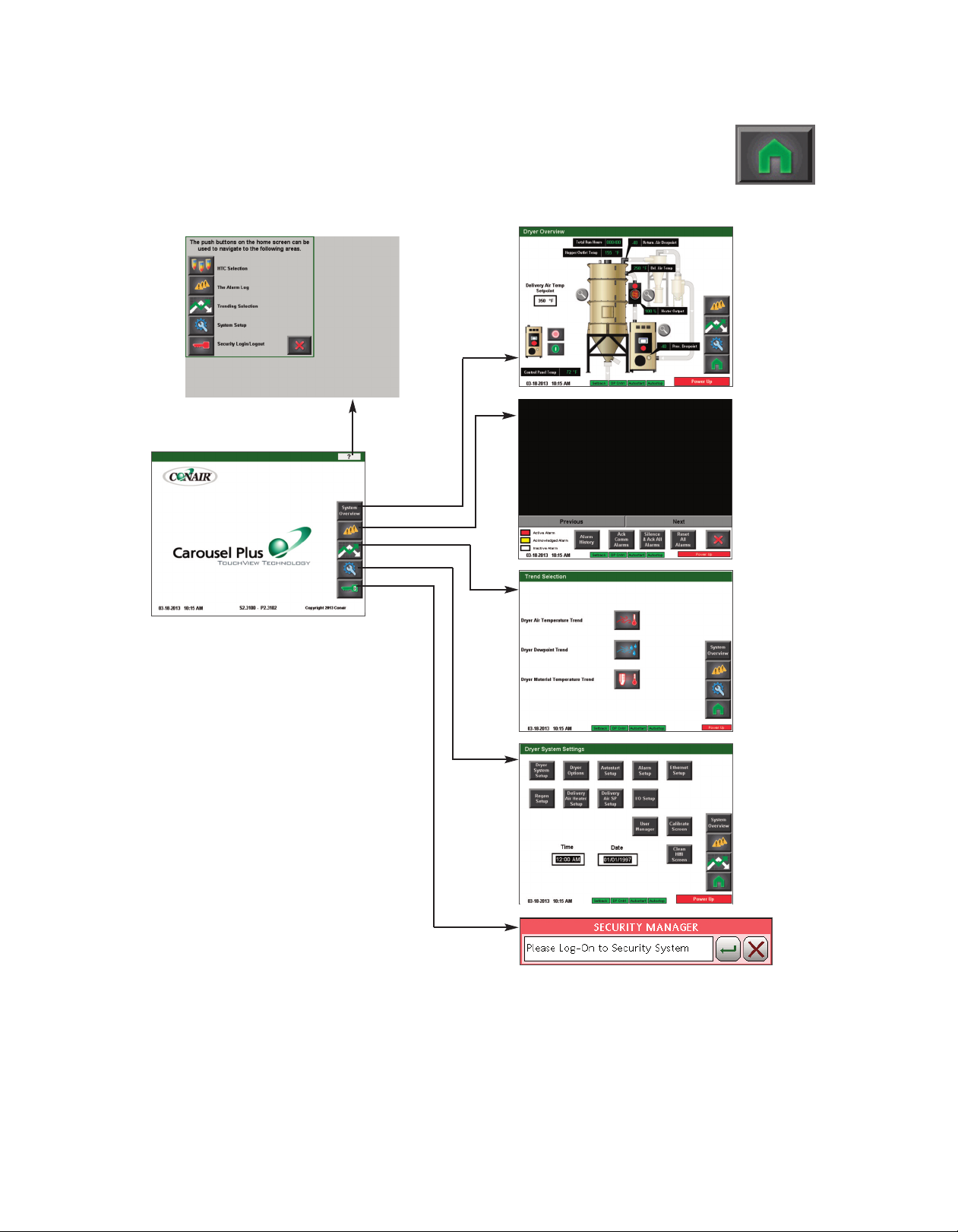
C o n t r o l F u nc t i o n F l o w C ha r t s
F ro m th e Hom e sc r ee n
Home
Help
Overview
Dryer
Overview
Alarms
Trend
Selection
4 - 4 6 l O pe ra ti on
Setup
Login/
Logout
Page 81
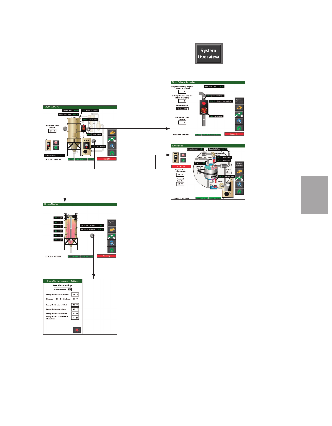
C o n t r o l F u nc t i o n F l o w C ha r t s
F ro m th e Ove r vie w sc r ee n
Dryer Overview
Dryer DM-II
Drying Monitor
80
2
250
50
3
Air Heater
D
r
y
e
r D
e
t
a
il
O p era tio n
4
Dryer Delivery
DM-II Low
A
lar
m
Set
t
in
g
s
O p e r at io n l 4 - 4 7
Page 82

Home
C o n t r o l F u nc t i o n F l o w C ha r t s
F ro m th e Ala r m s c re e n
Alarms
Alarm Banner Pop-up
4 - 4 8 l O pe ra ti on
Page 83
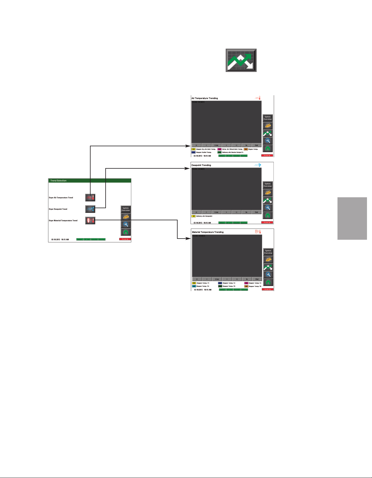
C o n t r o l F u nc t i o n F l o w C ha r t s
F ro m th e Tr e nd S ele c ti o n s c ree n
Air Temp.
Trending
Trend
Selection
Dewpoint
Trending
O p era tio n
4
Material
Temperature
Trending
(if installed)
( C o nt i nu ed )
O p e r at io n l 4 - 4 9
Page 84
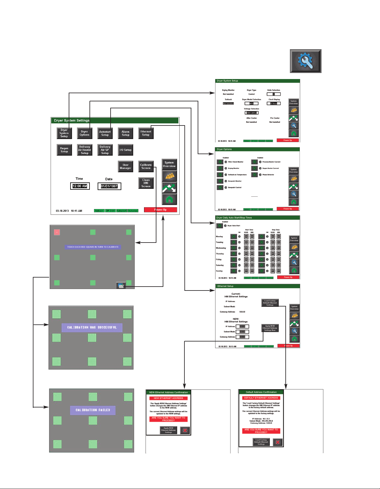
Setup
C o n t r o l F u nc t i o n F l o w C ha r t s
F ro m th e Set u p s c re e n
Dryer System
Setup
Dryer Options
Autostart
Setup
or
4 - 5 0 l O pe ra ti on
Apply
Settings
Ethernet
Setup
Default
Settings
( C o nt i nu ed )
Page 85
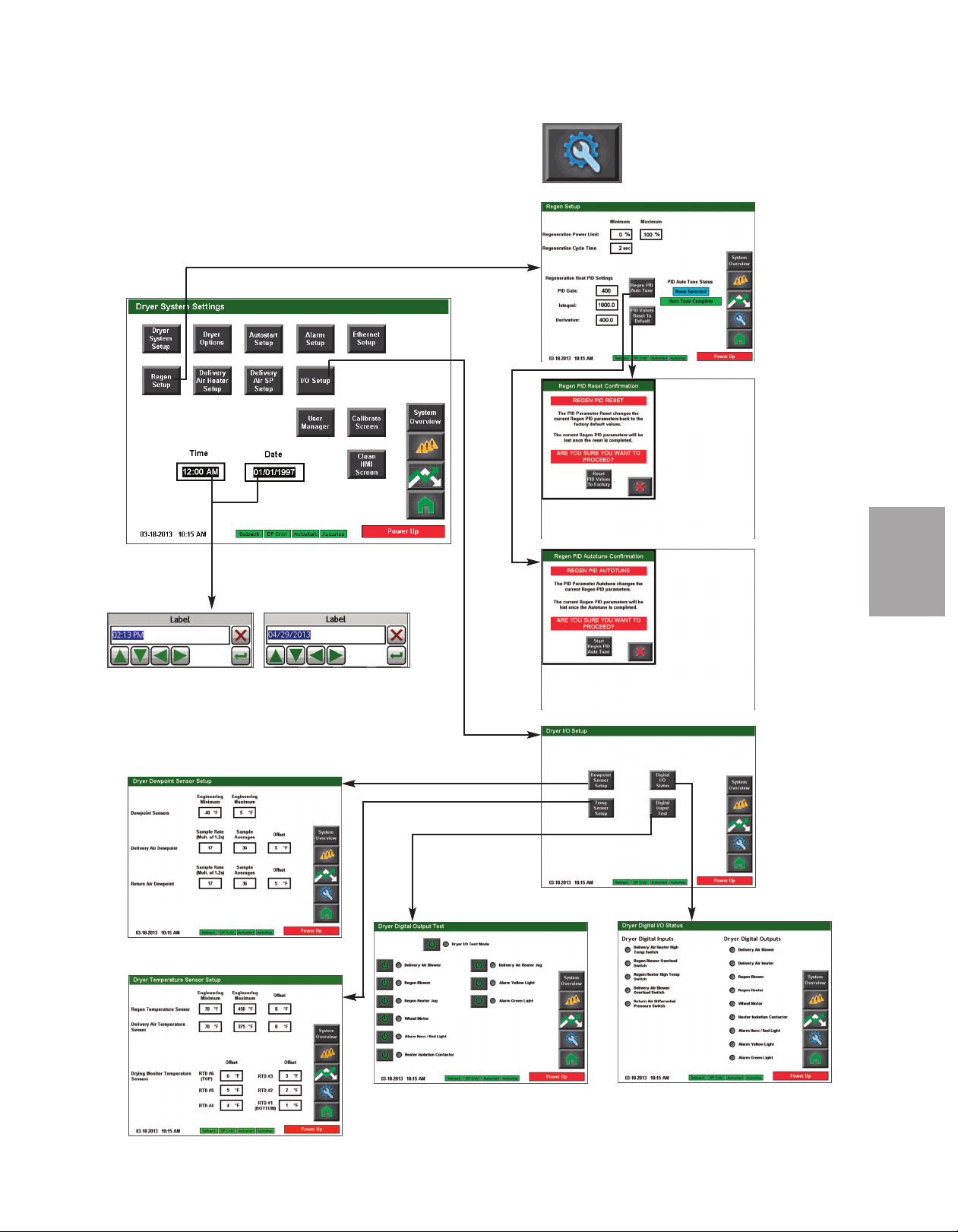
C o n t r o l F u nc t i o n F l o w C ha r t s
F ro m th e Set u p s c re e n (c on ti n ue d)
Setup
Set Time
and Date
Regen
Setup
Regen PID
Auto Tune
O p era tio n
4
PID Values
Reset To
Default
Dewpoint Setup
Temp Sensor Setup
Digital Output Test
( C o nt i nu ed )
I/O Setup
Digital I/O Status
O p e r at io n l 4 - 5 1
Page 86
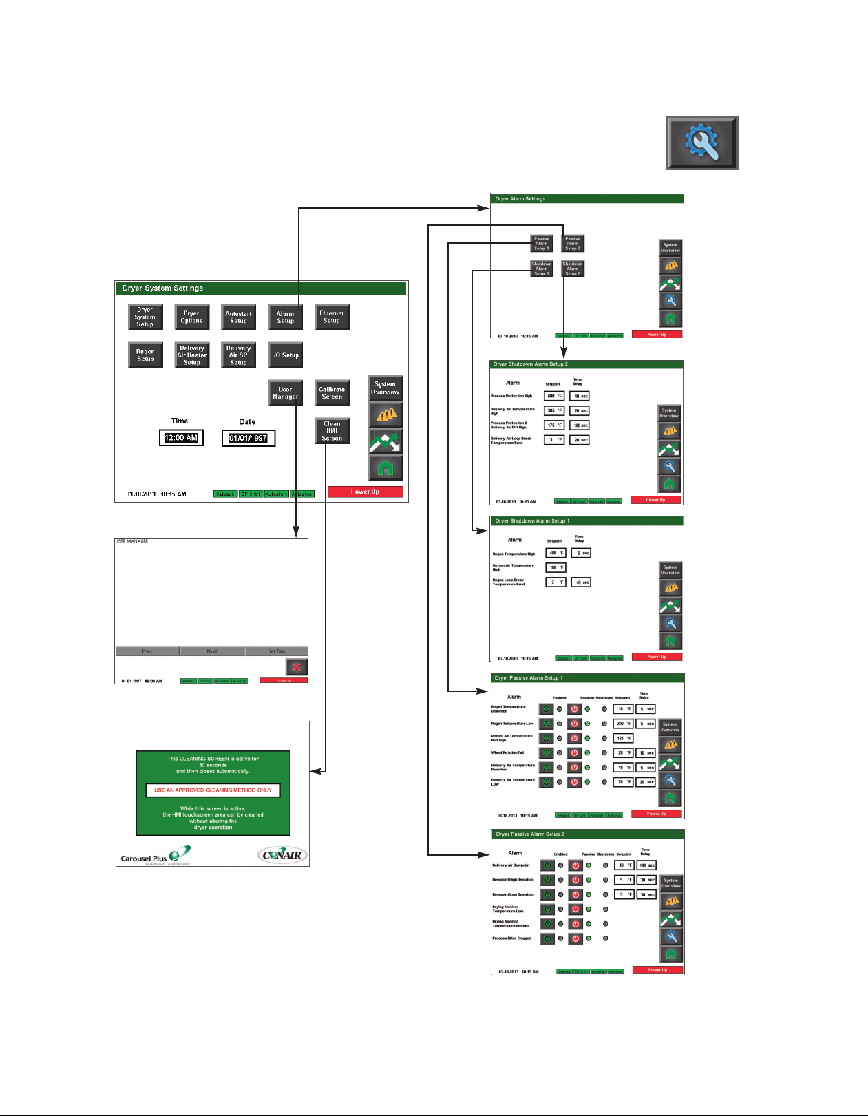
Setup
C o n t r o l F u nc t i o n F l o w C ha r t s
F ro m th e Set u p s c re e n (c on ti n ue d)
Alarm
Setup
Shutdown
Alarm
Setup 2
User Manager
Clean Screen
Shutdown
Alarm
Setup 1
Passive
Alarm
Setup 1
Passive
Alarm
Setup 2
4 - 5 2 l O pe ra ti on
( C o nt i nu ed )
Page 87

C o n t r o l F u nc t i o n F l o w C ha r t s
F ro m th e Set u p s c re e n (c on ti n ue d)
Setup
Delivery Air
Heater Setup
Delivery Air
PID Autotune
O p era tio n
4
PID Values
Reset To
Default
( C o nt i nu ed )
O p e r at io n l 4 - 5 3
Page 88

Setup
C o n t r o l F u nc t i o n F l o w C ha r t s
F ro m th e Set u p s c re e n (c on ti n ue d)
Delivery Air
SP Setup
4 - 5 4 l Op er at io n
(continued)
Page 89
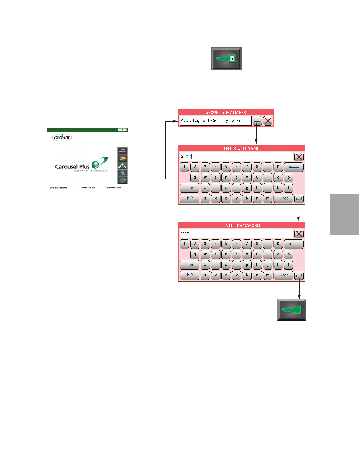
C o n t r o l F u nc t i o n F l o w C ha r t s
F ro m th e Log i n/ L og o ut s c re e n
Security Manager
Home
O p era tio n
4
6
O p e r at io n l 4 - 5 5
Page 90
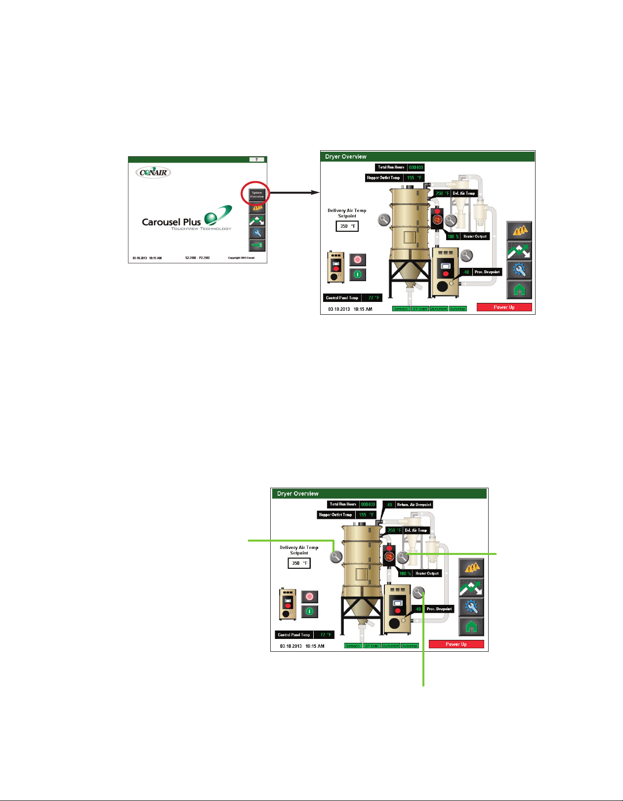
✐
NOTE: On this Overview screen,
live data is displayed. Data is
displayed as colored text inside a
solid black box. Set points boxes
are white with heavy black borders. Set points can be changed,
if the user has logged in at the
proper security level, by pressing
the set point boxes. This will
launch a pop-up keypad window
that can be used to change the
See Operation section
set point.
entitled, How to Navigate the
Control Screens.
set point value has been entered,
press the "Enter" key to lock in
the new set point.
After the new
C o n t r o l F u nc t i o n D e s cr i p t i o ns S t a n d A l o ne C on f i g u r at i o n
Dryer Overview Screen
To access the Dryer Overview Screen:
1 Press the Dryer Overview button located on the home screen.
The Dryer Overview screen provides the user with the current live information concerning
the delivery air temperature, the process dewpoint, the total run hours, and the ambient temperature.
This screen also allows the user to use the zoom buttons and select the dryer detail information or the hopper(s) detail information.
✐
NOTE: The dots on the Heater
Pack and dryer (shown as red on
the screen to the right) indicate
current operating status.
Red=stopped
Green=on/running
During the shut down process,
the dot on the dryer stays green
until has cooled down.
Cycling between red and green
on the heater pack is normal.
This indicates that the heater is
turning on and off as necessary.
4 - 5 6 l O pe ra ti on
DM-II zoom
(if applicable)
Delivery
Air
Heater
zoom
Dryer zoom
Page 91
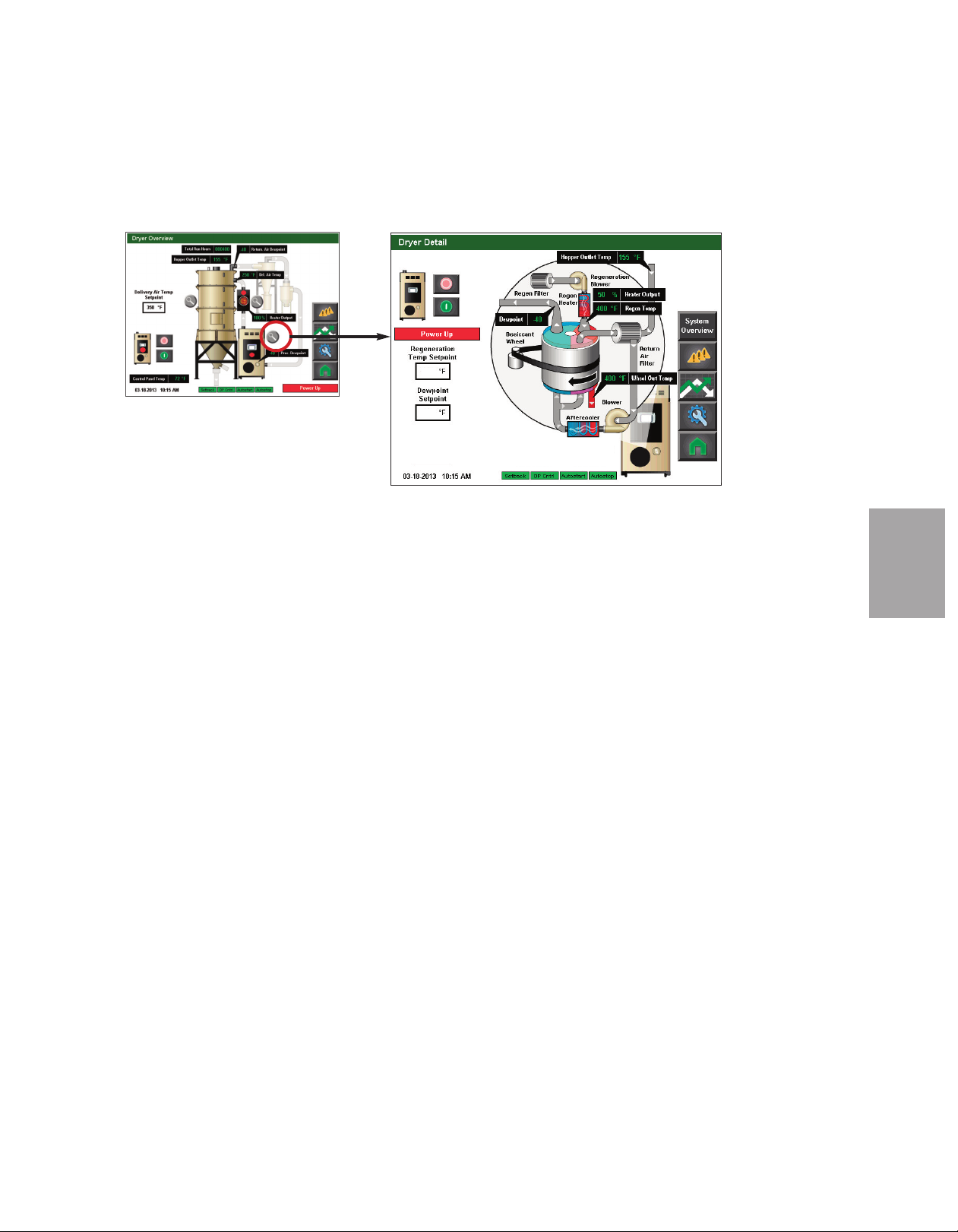
C o n t r o l F u nc t i o n D e s cr i p t i o ns S t a n d A l o ne C on f i g u r at i o n
Dryer Detail Screen
350
-20
To access the Dryer Detail screen:
( c o nt i nu ed )
1 Press the Magnifying Glass (zoom) button associated with the dryer on the Dryer
Overview screen.
O p era tio n
4
This screen allows the user to start or stop the dryer.
The Dryer Detail screen provides the user with the current live information concerning the
processes within the dehumidifying dryer including:
• Hopper Outlet Temperature (if equipped with setback)
• Heater Output
• Regeneration Temperature (Regen. Temp)
• Dewpoint
• Wheel Out Temperature (Temp)
It also tells the user the current status of the aftercooler and precooler (if applicable), as well
as which features (Autostart, Autostop, Setback, Dewpoint Control) are enabled.
If the user is logged-in at the proper security level, setpoint changes can be made to:
• Regeneration Temperature Setpoint
• Dewpoint Setpoint
The user can also view the other system parameters, view alarms, view trending, return to
the Dryer Overview screen, or return to the Home screen by pressing the applicable buttons
on the right of the screen.
✐
NOTE: Live data is displayed as
colored text inside a solid black
box. Set points boxes are white
with heavy black borders. Set
points can be changed, if the user
has logged in at the proper security level, by pressing the set
point boxes. This will launch a
pop-up keypad window that can
be used to change the set point.
See Operation section entitled,
How to Navigate Control Screens.
After the new set point value has
been entered, press the "Enter"
key to lock in the new set point.
O p e r at io n l 4 - 5 7
Page 92

✐
NOTE: Depending on which options
your dryer has been configured
with, and whether or not you have
the DM-II Drying Monitor enabled,
your screens and icons may appear
different.
C o n t r o l F u nc t i o n D e s cr i p t i o ns -
S t a n d A l o ne C on f i g u r at i o n ( c on ti nu e d)
Delivery Air Heater Screen
280
250
To access the Delivery Air Heater screen:
1 Press the Magnifying Glass (zoom) button associated with the heater on the Dryer
Overview screen.
✐
NOTE: On this screen, live data is
displayed as well as setpoints
which can be changed. Data is
displayed as colored text inside a
solid black box. Setpoints boxes
are white with heavy black borders. Setpoints can be changed,
if the user has logged in at the
proper security level, by pressing
the set point boxes. This will
launch a pop-up keypad window
that can be used to change the
setpoint.
See Operation section
entitled, How to Navigate the
Control Screens.
setpoint value has been entered,
press the "Enter" key to lock in
the new set point.
After the new
The Dryer Detail screen provides the user with the current live information concerning the
processes within the dehumidifying dryer including:
• Heater Output
• Process Protection Temperature
• Delivery Air Temperature
It also tells the user the current status of the heater, as well as which features of the dryer
(Autostart, Autostop, Setback -if equipped, Dewpoint Control) are enabled.
If the user is logged-in at the proper security level, setpoint changes can be made to:
• Hopper Outlet Temperature Setpoint
• Delivery Air Temperature Setpoint
• Delivery Air Temperature Setpoint (for setback - if equipped)
• Hopper Setback activation
This screen also allows the user to view the other system parameters, view alarms, view
trending, return to the Dryer Overview screen, or return to the Home screen by pressing the
applicable buttons on the right of the screen.
4 - 5 8 l O pe ra ti on
Page 93

C o n t r o l F u nc t i o n D e s cr i p t i o ns S t a n d A l o ne C on f i g u r at i o n
DM-II Drying Monitor Screen (if equipped)
To access the DM-II Drying Monitor
screen:
1 Press the Magnifying Glass (zoom)
button associated with the Drying
Monitor (beside the hopper).
( c o nt i nu ed )
✐
NOTE: Depending on
which options your dryer
has been configured with,
and whether or not you
have the DM-II Drying
Monitor enabled, your
screens and icons may be
different from what is
shown here.
O p era tio n
4
The DM-II Drying Monitor screen provides
the user with the current alarm location
zone, and the Alarm Setpoint, as well as a
button to zoom to DM-II settings. These
settings can be adjusted.
✐
NOTE: On these screens, live data is displayed as well as setpoints which can be changed. Data is displayed as colored text inside a solid black box. Setpoints boxes are white with heavy black borders.
Setpoints can be changed, if the user has logged in at the proper security level, by pressing the set point
boxes. This will launch a pop-up keypad window that can be used to change the setpoint.
Operation section entitled, How to Navigate the Control Screens.
entered, press the "Enter" key to lock in the new set point.
After the new setpoint value has been
See
✐
NOTE: See the Drying Monitor
User Guide for more information
about using the Drying Monitor.
O p e r at io n l 4 - 5 9
Page 94
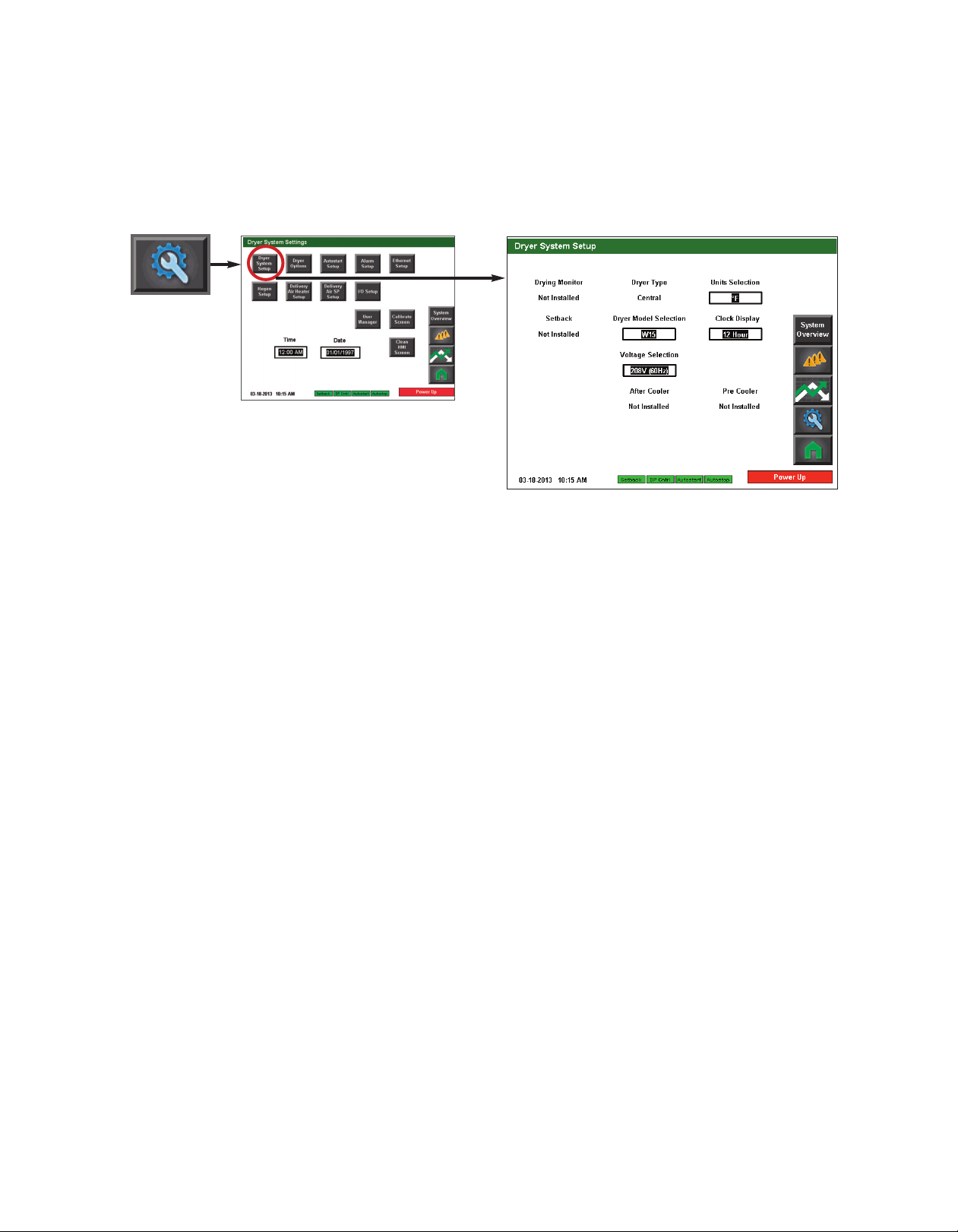
C o n t r o l F u nc t i o n D e s cr i p t i o ns -
✐
NOTE: Your DC-T control should
have been configured at the factory
for your Dryer. These settings
should not need changed unless
your system changed, or the control
was replaced. Proper login is
required to change these settings.
S t a n d A l o ne C on f i g u r at i o n
Dryer System Setup screen
To access the Dryer System Setup screen:
1 Press the Settings button from the Home screen.
2 Press the Dryer System Setup button.
( c o nt i nu ed )
✐
NOTE: See the DM-II User
Guide for more information
about using the DM-II Drying
Monitor.
The Dryer System Setup screen provides the user with the ability to change the system settings of this Dryer.
This screen allows you to change:
• Units selection (Fahrenheit and Celsius)
• Dryer model
• Clock display (12 hour and 24 hour)
• Voltage selection
4 - 6 0 l O pe ra ti on
Page 95

C o n t r o l F u nc t i o n D e s cr i p t i o ns S t a n d A l o ne C on f i g u r at i o n
Dryer Options screen
To access the Dryer Options screen:
1 Press the Settings button from the Home screen.
2 Press the Dryer Options button.
The Dryer Options screen provides the user with the ability to enable or disable options.
( c o nt i nu ed )
O p era tio n
4
This screen allows you to change the status of:
• Filter Check Monitor
• Drying Monitor
• Setback
• Dewpoint Monitor
• Dewpoint Control
• Process Heater Current
• Regen Heater Current
• Phase Detector
✐
NOTE: Depending on the configuration of your dryer and your drying system, some of the options may not be
available or visible on your screen. Your screen may appear different from what is shown here.
✐
NOTE: Proper login is
required to change these settings.
O p e r at io n l 4 - 6 1
Page 96
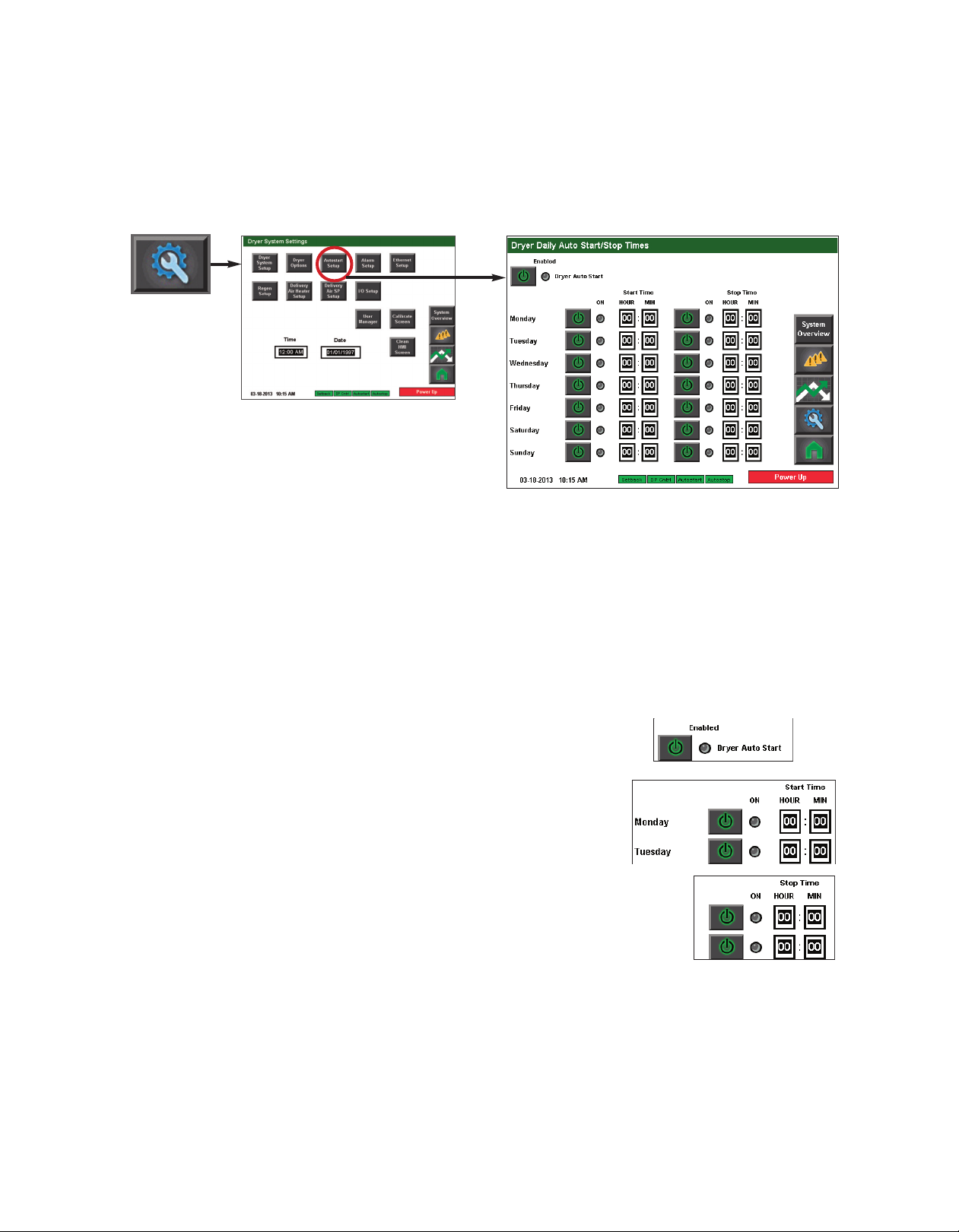
✐
NOTE: Proper login is required to
change these settings.
C o n t r o l F u nc t i o n D e s cr i p t i o ns S t a n d A l o ne C on f i g u r at i o n ( c on ti nu e d)
Autostart Setup screen
To access the Autostart screen:
1 Press the Settings button from the Home screen.
✐
NOTE: Autostart timer uses 24
hour time format. 00:00 is midnight. Note that this is a seven (7)
day repeating calendar, and not real
time.
2 Press the Autostart Setup button.
The Autostart Setup screen provides the user with the ability to enable or disable and set the
start and stop time for dryer for each day of the week.
To setup Auto Start and Auto Stop:
1 Press the Enable button to enable Dryer Auto Start.
2 Press the Enable button next to each day of the
week you would like to set the Auto Start time.
3 Set the Auto Start time for each day you have
enabled.
4 Press the Enable button next to each day of the week you
would like to set the Auto Stop time.
5 Set the Auto Stop time for each day that you have enabled.
4 - 6 2 l O pe ra ti on
Page 97
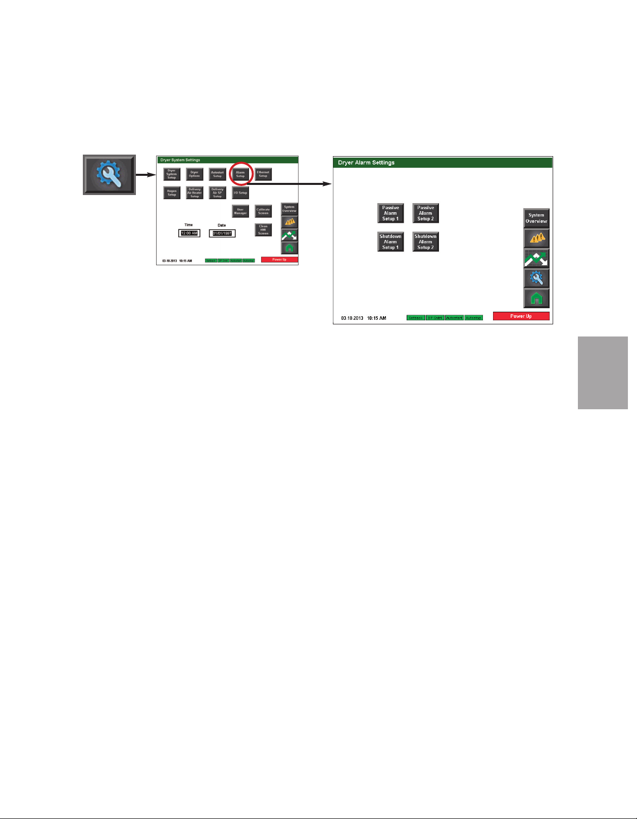
C o n t r o l F u nc t i o n D e s cr i p t i o ns S t a n d A l o ne C on f i g u r at i o n ( c on ti nu e d)
Alarm Setup screen
To access the Alarm Setup screen:
1 Press the Settings button from the Home screen.
2 Press the Alarm Setup button.
The Alarm Setup screen provides the user with the ability to enable, disable and adjust setpoints for alarms in the Drying system. Both passive and shutdown alarms can be modified
from these screens.
✐
NOTE: Proper login is required to change these settings.
O p era tio n
4
O p e r at io n l 4 - 6 3
Page 98
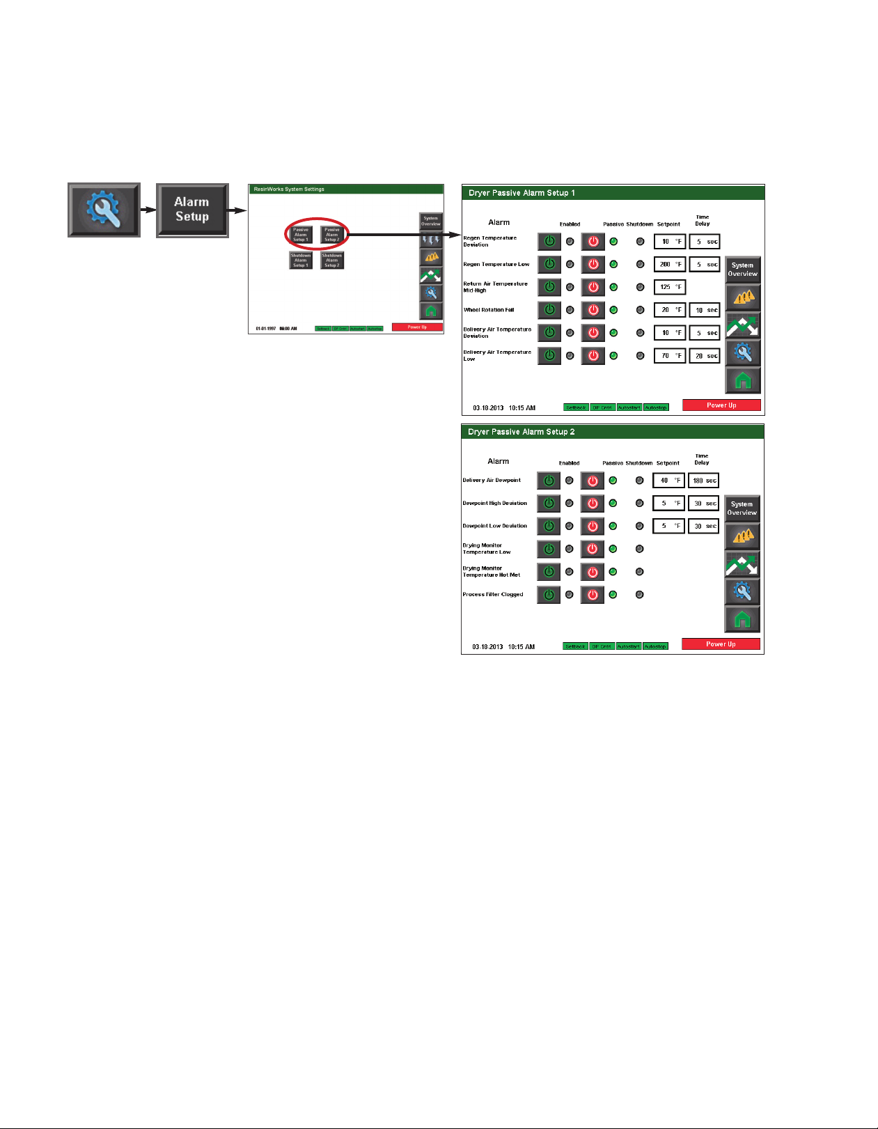
✐
NOTE: Some alarms require
the user to enable the alarm,
and to choose between
Passive or Shutdown alarm
type. The first “power” button
enables or disables the alarm.
The second button chooses
between Passive or Shutdown
alarm.
C o n t r o l F u nc t i o n D e s cr i p t i o ns S t a n d A l o ne C on f i g u r at i o n ( c on ti nu e d)
Passive Alarm Setup (1 & 2)
IMPORTANT: Factory
default alarm setpoints
should not be changed
without first consulting
with Conair.
Conair’s Instant Access
24/7 Parts and Service
number is
800-458-1960.
Outside the U.S., dial
814-437-6861.
To access the Passive Alarm Setup screens:
1 Press the Settings button from the Home screen.
2 Press the Alarm Setup button.
3 Press the Passive Alarm Setup button for the Passive alarms you would like to config-
ure (screen 1 or screen 2- if applicable).
4 Enter the desired setpoint and delay (if applicable) for each alarm.
✐
NOTE: Proper login is required to modify alarm settings. Depending on your dryer
configuration, you may have different alarm settings or different screen configurations.
4 - 6 4 l O pe ra ti on
Page 99
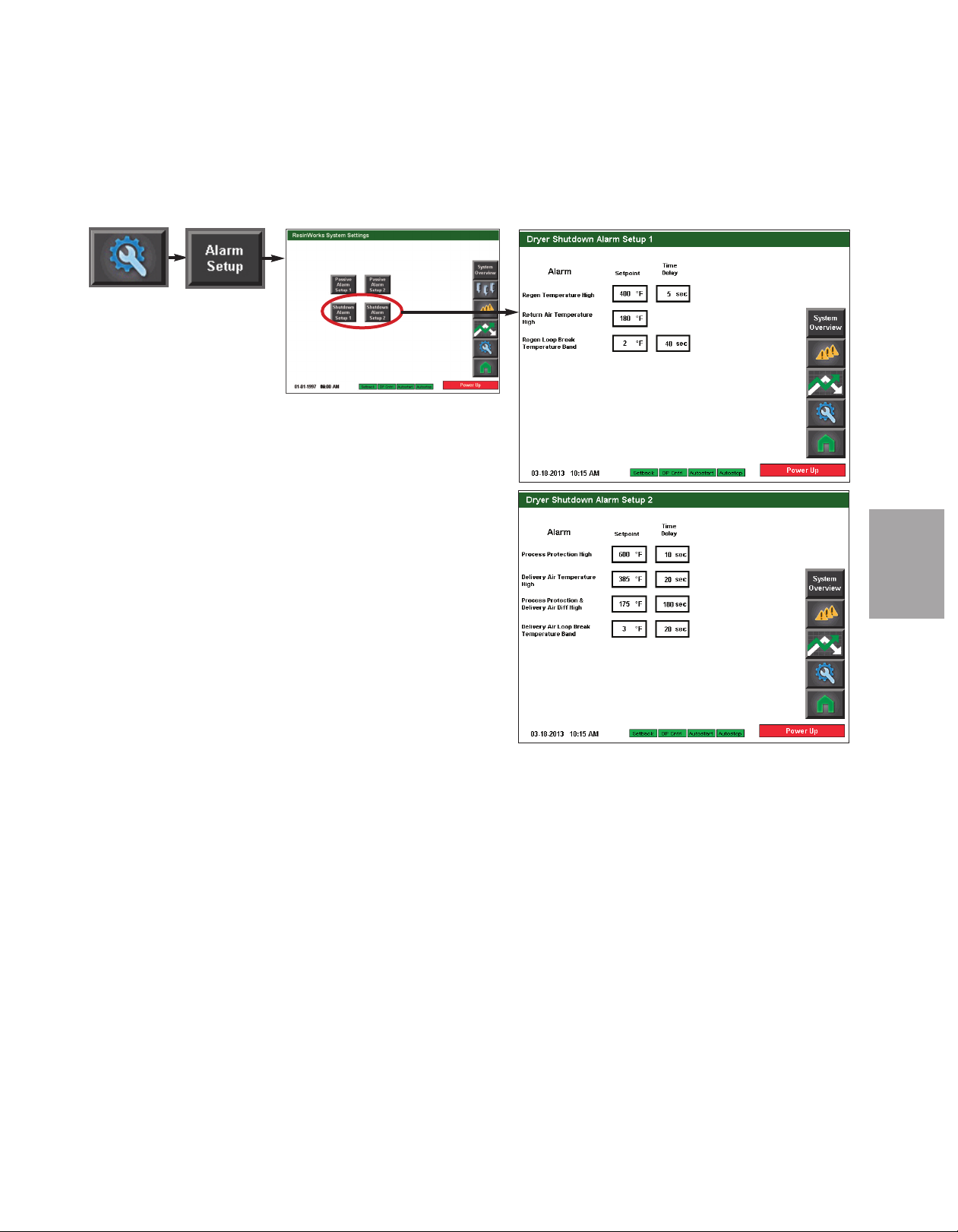
C o n t r o l F u nc t i o n D e s cr i p t i o ns S t a n d A l o ne C on f i g u r at i o n ( c on ti nu e d)
Shutdown Alarm Setup (1 & 2)
To access the Shutdown Alarm Setup screens:
1 Press the Settings button from the Home screen.
2 Press the Alarm Setup button.
3 Press the Shutdown Alarm Setup button for the Shutdown
alarms you would like to configure (screen 1 or screen 2 - if
applicable).
4 Enter the desired setpoint and delay for each shutdown
alarm.
O p era tio n
4
✐
NOTE: Proper login is required
to modify alarm settings.
IMPORTANT: Factory
default alarm setpoints
should not be changed
without first consulting
with Conair.
Conair’s Instant Access
24/7 Parts and Service
number is
800-458-1960.
Outside the U.S., dial
814-437-6861.
O p e r at io n l 4 - 6 5
Page 100
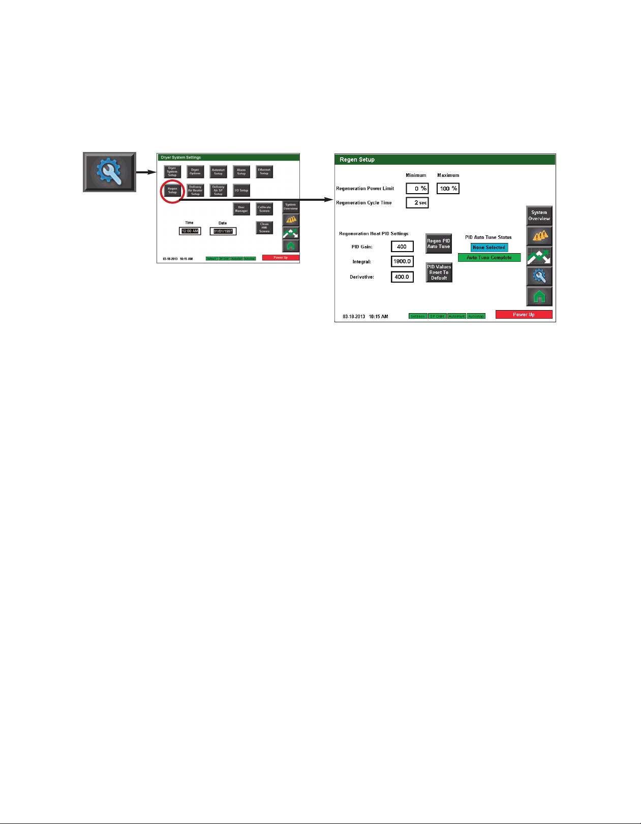
C o n t r o l F u nc t i o n D e s cr i p t i o ns -
✐
NOTE: Proper login is required to
change these settings.
S t a n d A l o ne C on f i g u r at i o n
Regen Setup screen
To access the Regen Setup screen:
1 Press the Settings button from the Home screen.
2 Press the Regen Setup button.
( c o nt i nu ed )
✐
NOTE: It is not typically necessary to use the Regen PID Auto Tune or the Reset PID Values to Factory button.
Contact the Conair Service department if you h ave questions about these items. Conair’s Instant Access 24/7
Parts and Service number is 800-458-1960. Outside the U.S., dial 814-437-6861.
4 - 6 6 l O pe ra ti on
 Loading...