

Page 1

E3FOM
User’s Manual
Page 2

Page 3

i
Table of Contents
CHAPTER 1 INTRODUCTION..........................................................................................1
1-1 FUNCTIONAL DESCRIPTION .............................................................................................1
1-2 APPLICATIONS OF E3FOM .............................................................................................. 2
1-3 E3FOM TECHNICAL SPECIFICATIONS .............................................................................3
1-4 E3FOM ORDERING INFORMATION ..................................................................................6
CHAPTER 2 INSTALLATION GUIDE .............................................................................7
2-1 DESCRIPTION ..................................................................................................................7
2-2 UNPACKING..................................................................................................................... 7
2-3 SITE REQUIREMENTS....................................................................................................... 7
2-4 SITE SELECTION ..............................................................................................................8
2-5 AC OR DC ELECTRICAL OUTLET CONNECTION ..............................................................8
CHAPTER 3 OPERATING INSTRUCTIONS..................................................................9
3-1 PANEL DESCRIPTION ....................................................................................................... 9
3-2 FRONT PANEL CONTROL AND LED INDICATOR FUNCTIONS........................................... 10
3-3 MENU TREE ..................................................................................................................12
CHAPTER 4 OPERATING AND SETUP INSTRUCTIONS.........................................14
4-1 PROFILE ........................................................................................................................14
4-2 SYSTEM CONFIGURATION.............................................................................................. 15
4-3 LOOPBACK TEST FUNCTION .......................................................................................... 15
4-4 OPTICAL MODULE MANUAL SWITCH............................................................................15
4-5 PERFORMANCE MONITORING FUNCTION....................................................................... 15
4-6 NETWORK MANAGEMENT FUNCTION............................................................................17
4-7 CRAFT PORT OPERATION...............................................................................................21
4-8 CONNECT AND SETUP THE CRAFT PORT ........................................................................21
4-9 OPERATING FROM THE CRAFT PORT.............................................................................. 21
CHAPTER 5 DIAGNOSTICS AND LOOPBACK FUNCTIONS..................................36
5-1 GENERAL INFORMATION................................................................................................36
5-2 LOOPBACK FUNCTIONS .................................................................................................36
Page 4

Page 5

1
Chapter 1 Introduction
1-1 Functional Description
Comxion E3FOM is a high-speed fiber optics modem that converts E3 signal into an
optical data stream. It extends the transmission distance up to 80 kilometers. With the
optional secondary optical link, E3FOM provides 1+1 optical line protection. In addition,
the E3FOM also provides the standard SNMP interface for Network Management, using
Ethernet and PPP ports to connect to the central office. Users can monitor and configure
the E3FOM through in-band operation channel to reach a remote terminal. Moreover,
E3FOM simplifies testing and maintenance with order wire, allowing voice communication
between local and remote maintenance crews.
Transparent E3 signal between electrical and optical link
1+1 auto-protection switch for optical link
1310/1550 nm optical MLM mode laser for customer applications
16 – 52 dB optical system gain
SNMP agent for local/remote unit management and performance monitoring that
included E3 and optical links
Provides BPV error count for E3 interface performance monitoring
Provides performance monitoring for optical interface
LAN and PPP ports are provided for SNMP management.
Embedded Operation Channel (EOC) for remote unit performance monitoring and
configuration
Provides local/remote loopback and request for remote loopback for diagnostics
Compliant with ITU-T G.703 E3 electrical interface
Compliant with ITU-T G.823 E3 jitter tolerance
Compliant with ITU-T G.751 E3 jitter transfer
Order wire (OW) channel is available for end-to-end installation and maintenance.
Easy installation and status monitoring through LCD panel and keypad or VT-100
terminal
ELOS/AIS/RDI LED indicators for E3 electrical link
OLOS/AIS/RDI LED indicators for optical link
Central office visible/audible alarm relay
Stand-alone or 19” / 23” rack-mounted
Redundant power supply with DC/AC options
Compliant with ITU-T G.652 single mode fiber transmission medium
Page 6
2
1-2 Applications of E3FOM
E3FOM is mainly used to extend the transmission distance of E3 signal, connecting
different Local Area Networks (LAN), by converting E3 signal into an optical data stream.
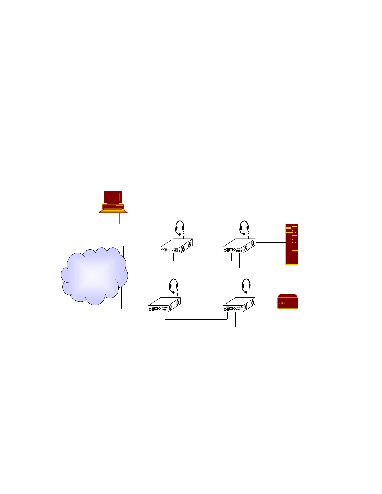
As illustrated below, there are two main applications for the use of E3FOM:
¾ Application 1: E3FOM converts the E3 signal into an optical data stream to extend the
transmission distance.
¾ Application 2: E3FOM can connect a router with HSSI interface to a remote Central
Office.
E3FOM
SL-FE340
E3
HSSI
34Mbps
10M
SNMP
Agent
EMS
Optical
Link
CO. Side Remote Side
OW
OW
SDH/DACS
Network
Optical
Link
SL-FE340
E3
HSSI
34Mbps
10M
SNMP
Agent
EMS
Optical
Link
CO. Side Remote Side
OW
OW
SDH/DACS
Network
Optical
Link
Page 7

3
1-3 E3FOM Technical Specifications
E3 Interface
¾ Channel Capacity: 1 channel
¾ Bit Rate: 34.368Mbps +/- 20ppm
¾ Line Code: HDB3
¾ Impedance: Unbalanced 75Ω
¾ Electrical Interface: Compliant with ITU-T G.703
¾ Jitter Tolerance: Compliant with international standards ITU-T G.823
¾ Jitter Transfer: Compliant with international standards ITU-T G.751
HSSI Interface (Optional)
¾ Data Rate: 34 Mbps (clear channel)
¾ Electrical: MC10KH series ECL
¾ Physical: 50 pin SCSI-2 socket
Optical Link
¾ Wavelength: 1310 or 1550 nm MLM Laser diode
¾ Number of Optical Link:2 (working and protection link)
¾ Output Power: >-15 dBm at 9/125 (1310 nm Laser)
>-5 dBm at 9/125(1550 nm Laser)
¾ Receive Sensitivity: -34 dBm (1310 nm Laser) or
-35 dBm (1550 nm Laser)
¾ System Gain: > 19 dB
¾ Fiber type: Single Mode (9/125um)
¾ Connectors: FC/PC or ST
Alarm Detection and Indication
z E3 Signal Interface
¾ ELOS (Electric Loss of Signal): The loss of E3 signal
¾ AIS (Alarm Indication Signal): Receiving alarm signal indicator
¾ RDI (Remote Defect Indication): Remote alarm
Page 8

4
z Optical Interface
¾ OLOS (Optical Loss of Signal): The loss of optics signal
¾ AIS (Alarm Indication Signal): Receiving alarm signal indicator
¾ LCK (Lock): Disables auto protection switch
¾ RDI (Remote Defect Indication): Remote alarm
¾ LSR: Laser On indicator
z System Interface
¾ SYS: System power module and control module failure detection
¾ Alarm Connector: DB-9 female connector to an external BUZZER for
audible alarm.
¾ RNG: Indicator that will light up when the “Call” button is pressed or
when connected to another unit via order wire.
Diagnostic capabilities
¾ Loopback: Local Loopback, and Remote Loopback, Request Remote
Loopback
¾ ACO: Cutting off the audible alarm (to external buzzer) will still keep
the visible ACO light on. Disabling the audible alarm does not mean
the problem has been solved.
¾ RST: Reset the system
Configuration
¾ Use the three control buttons and the LCD front panel to configure and monitor
the system
¾ Craft port:
¾ Bits per second (baud): 9600bps
¾ Parity: None
¾ Data Bits: 8 bits
¾ Stop Bit: 1
(VT-100 or Emulation Terminal)
Power
¾ DC: -36V ~ -72V
¾ AC: 90V ~ 264V (57Hz ~ 63Hz)
Page 9

5
System Mechanical
¾ E3FOM Dimensions:
Depth: 220 mm
Width: 285 mm
Height: 44.5 mm
¾ Connectors: E3: BNC female connector
HSSI: 50 pin SCSI-2 socket
Order Wire: Phone jack
SNMP: Two RJ-45 for LAN and PPP ports
Office Alarm: D-type 9 pin female connector
Environmental Conditions
¾ Operating Temperature: 0 ~ 45℃ Indoor Application
0 ~ 60℃ Outdoor Application
-25 ~ 70℃ Storage
¾ Relative Humidity: 5 ~ 95% without condensation
¾ EMI (Electromagnetic Interference): The Modem complies with specifications
of class A of 22 of the CISPR (International Special Committee on Radio
Interference of the International Electrotechnical Commission) or class A
of Subpart B of Part 15 of the FCC (Federal Communications
Commission) Rules of U.S.A.
¾ EMS: Compliant with EN55082-2 standards
¾ Safety: Compliant with EN60950 standards
Page 10

6
1-4 E3FOM Ordering Information
Classification Item
Single Optical Link Optical Link Type
Dual Optical Link (1+1 auto protection)
1310nm Multi-Mode Laser Module
1310nm Single-Mode Laser Module, 30Km
1310nm Single-Mode Laser Module, 50Km
1310nm Single-Mode Laser Module, 70Km
1550nm Single-Mode DFB Laser Module, 80Km
1310nm Single-Mode Laser Module, 90Km
Laser Module Type
1550nm Single-Mode DFB Laser Module, 100Km
FC/PC Type Laser Module Connector
SC Type Laser Module Connector
Laser Module
Connector Type
ST Type Laser Module Connector
Single AC Power Module
Dual AC power Module
Single DC Power Module
Dual DC Power Module
Power Module Type
One AC and One DC Power Module
USA (1.8 M)
Europe
England
Power Cord
Australia
Page 11

7
Chapter 2 Installation Guide
2-1 Description
This chapter provides the information needed to install E3FOM. It is important to
follow the installation instructions to ensure normal operation of the system and to prevent
damages due to human error.
2-2 Unpacking
If there is a possibility for future relocation of the E3FOM unit, please save the cartons
and the protective packaging material. The following items are shipped with your
E3FOM:
z
One E3FOM User’s Manual
z
One E3FOM Unit
z
RJ45-to-DB9 connector
Please carefully unpack and inspect the unit and accessories for potentially damaged
and missing parts. Contact our nearest sales representative or our company directly if you
suspect any damaged or missing parts. Improper handling during shipment may cause early
failure.
2-3 Site Requirements
The F.C.C. requires telecommunication equipment to withstand electrical surge that
may result from lighting strikes. This equipment has been tested and found to comply with
the F.C.C. requirement. Users should follow the precautions below to insure the safety and
minimize the risk of damage to the equipment:
z
Make sure that the power outlet is properly grounded.
z
Proper grounding should include a minimum of:
1) A grounded rod buried outside the building at least 8 feet (2.44 meters) deep.
2) It is preferred that the building uses metal water pipe and cooper connector at the
joint.
3) Any device either connected to E3FOM directly or indirectly, should use the same
set of power outlet.
Page 12

8
2-4 Site Selection
For best performance, install the E3FOM within 50 feet (15.24 meters) from the data
terminal equipment and 6 feet (1.83 meters) from the AC power outlet. To allow easy
access to the equipment, leave at least 36 inches (90 cm) clearance in the front and at least 4
inches (10.2 cm) at the rear.
To avoid overheating, leave at least 1 inch (2.5 cm) on either side of E3FOM. Also,
do not stack another equipment on top of E3FOM.
2-5 AC or DC Electrical Outlet Connection
For safety and to prevent damages to E3FOM, make sure that the power requirement
matches those of your electric outlets. Connect power to E3FOM and power on the
equipment.
Page 13
9
Chapter 3 Operating Instructions
3-1 Panel Description
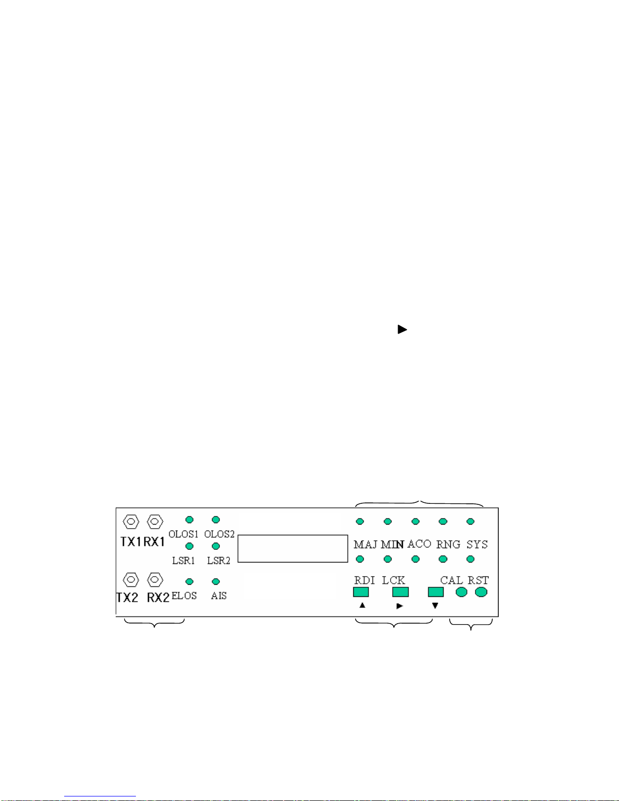
E3FOM consists of the front panel and the rear panel. There are four parts to the front
panel of E3FOM:
(1) Fiber Optics Connectors and Indicators:
▪ Include two sets of optics transmit/receive connectors and indicators (1+1 auto
switch protection).
▪ Notify users of a problem such as OLOS (Optical Loss of Signal), ELOS (Electric
Loss of Signal), AIS (Alarm Indication Signal) or LSR (Laser LED).
(2) Alarm LED Display: Notifies users of a problem such as MAJ (Major Alarm), MIN
(Minor Alarm), RDI (Remote Defect Indicator), ACO(Alarm Cut Off), RNG (Ringer),
LCK (Lock), or SYS (System Alarm).
(3) LCD Control Buttons: The three buttons, ▲, ▼, and are used for system
configuration and for the loopback test.
(4) Order Wire: Users can connect E3FOM to a headset and microphone for remote
configuration and testing.
Each of the LED indicators is described below in detail:
Front panel
Fiber Optics Connector
(Working and Protect)
LCD Control Buttons
LED
Order Wir e
E3FOM
Page 14

10
3-2 Front Panel Control and LED Indicator Function s
#
Control or LED
Indicators
Functions
1 OLOS1
OLOS2
LSR1
LSR2
Red light when there is a loss of input signal.
Yellow light when Laser module is sending out energy normally.
2 ELOS/AIS Red light when there is an Electric Loss of Signal (ELOS) of E3 signal.
Yellow light when received an Alarm Indication Signal (AIS) of E3
signal.
3 MAJ
Red light when there is a Major Alarm present
4 MIN
Yellow light when there is a Minor Alarm present
5 RNG Red light when E3FOM is connecting to a remote terminal or when
connected to the remote terminal.
6 SYS Yellow light when system power or control module fails
7 RDI Remote Defect Indication;
Yellow light when there is a failure in the remote side
8 LCK Yellow light when system is locked, if switched to protect line 6 times
within 10 minutes
9 ACO Alarm Cut Off; Yellow light when the ACO button is pressed to
manually disable the audible alarm when a problem occurs.
If any newer alarm is reported after the ACO button has been pressed,
the external alarm will activate again.
10 CAL Activate/deactivate the order wire
11 RST Restart the system
12 ▼
▲
Three control and configuring buttons for E3FOM
Page 15
11
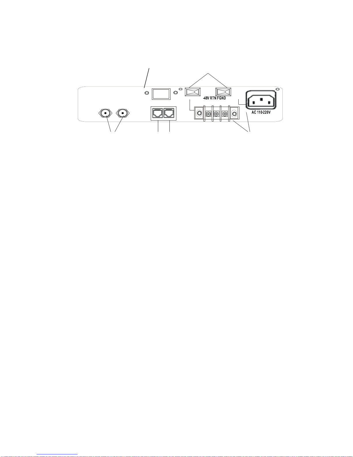
Rear Panel
E3 Signal Connector: BNC connector for input/output of E3 signal
I. Alarm: DB9 female connector; Connect to an external BUZZER to receive visible and
audible alarm.
II. Terminal Connector: a. LAN, RJ-45 connector to SNMP management system
b. PPP, RJ-45 (with DB9 converter) connector to a remote terminal
using dial-up modem
III. Power Switches: On/Off switch for E3FOM
IV. There are 5 different power supply combinations with the DC/AC dual module power
supple: AC only. DC only, dual AC, dual DC, AC/DC redundancy. (Refer to Order
Information)
BNC
電源開關
AC & D C電源插座
LAN RS232/PPP
終端接口 RJ45
BNC
LAN PPP /Craft port
Dual power
AC/DC
Alarm Power switch
Page 16
12
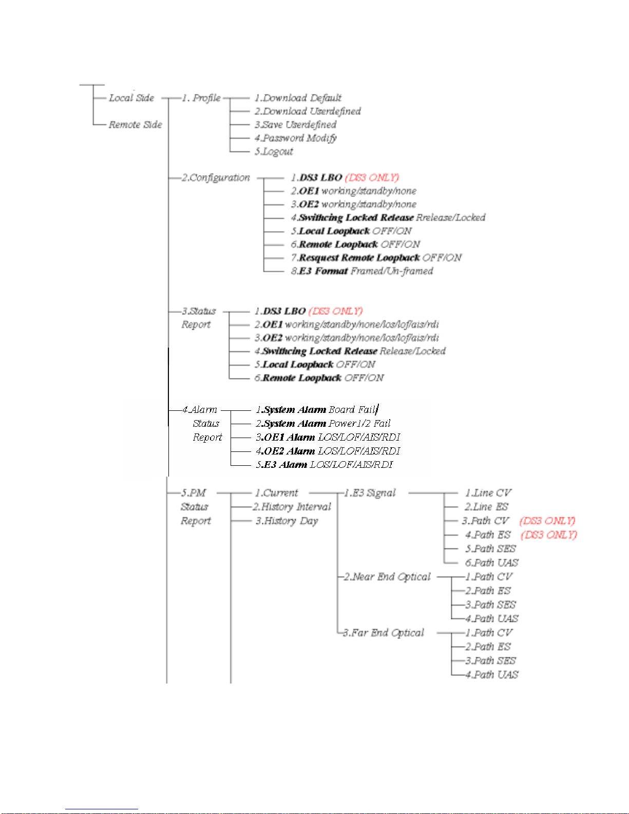
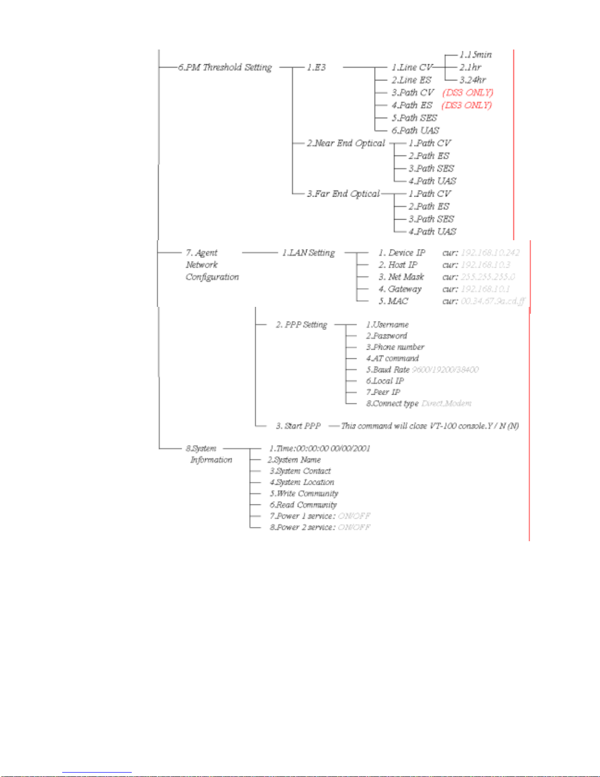
3-3 Menu Tree
E3FOM
Page 17
13
Page 18

14
Chapter 4 Operating and Setup Instructions
E3FOM provides LCD control for easy configuration, maintenance, and testing.
Button functions are as follows:
Menu select
▲ Go back to the upper level of the menu
▼ “Enter” key to go to a sub-menu
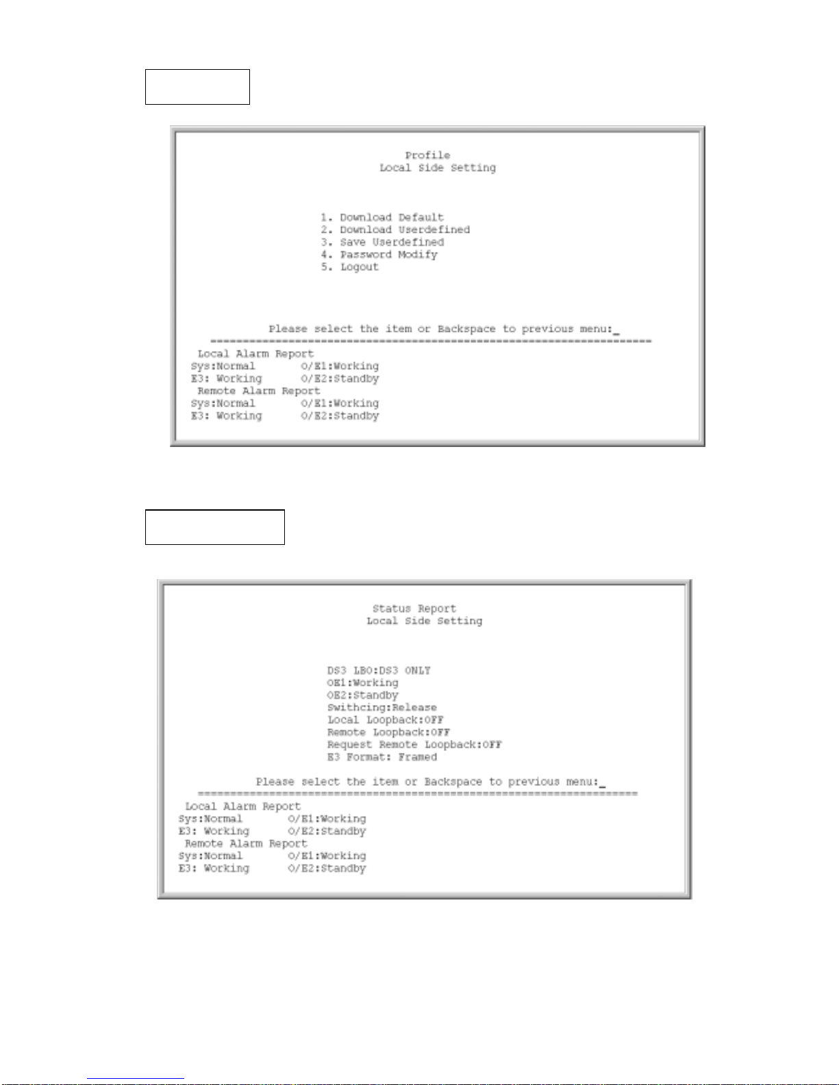
4-1 Profile
Download and Save Profiles:
If the user selects the factory default profile, the system will restart before downloading the
factory default profile.
Users can configure an E3 Line Code and Loopback test. After selecting the “user_ defined”
option, the system will automatically restart. The system will then download the
user_defined profile.
Modify Password:
To prevent unauthorized login, user must enter a set of password to login to the system.
The password for E3FOM is a combination of the buttons below, from left to right:
Button
Up ↑ Right →
Down
È
Up ↑
Password
U R D U
Users can change the password using this function after verifying the current password.
Password can also be changed from the craft terminal using the same procedure. Note that
the password for operating the craft can be different from LCD menu driven is needed.
Note: In case the user forgets the login password, the universal password for E3FOM
“URDU” can be used.
Page 19

15
4-2 System Configuration
z
The LBO of E3 signal cannot be configured on E3FOM. ( for T3FOM only)
z
The E3FOM can be configured as framed or un-framed in order to identify the LOS
alarm.
4-3 Loopback Test Function
There are three types of loopback tests for E3FOM: Local Loopback, Remote
Loopback, and Request Remote Loopback.
Note: Refer to Chapter 5 for detailed information on Diagnostics and Loopback
Functions.
4-4 Optical Module Manual Switch
Users can manually switch between OE module 1 and OE module 2 if a secondary OE
module is installed on the E3FOM.
O/E Module status can be obtained from this current menu:
z Under normal operation, LCD display shows that the working O/E Module as
“Working” and the backup O/E Module as ”Standby.”
z If E3FOM detects a Loss of Signal, the LOS light will be lit and the LCD display will
show that there is a Loss of Signal.
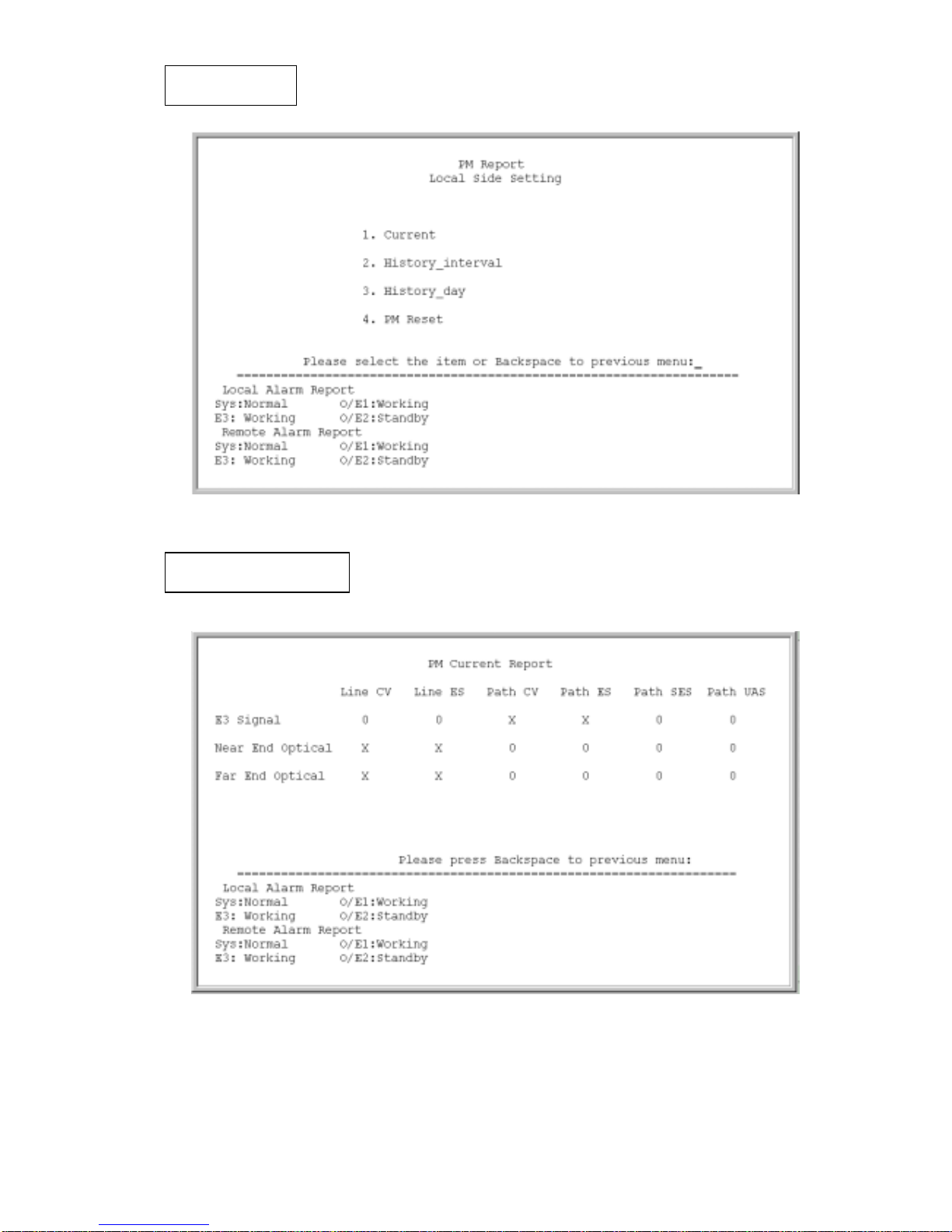
4-5 Performance Monitoring Function
The Performance Monitoring Function of E3FOM includes calculating errors in Path
and Line, providing performance monitoring parameters, and setting threshold value. To
access the performance monitoring function, select option 5: PM Status Report.
E3FOM has the following performance monitoring functions:
z Parameter:
* Near End Electrical:
Line Code Violation (Line CV)
Line Errored Second (Line ES)
Path Severely Errored Second (Path SES)
Path Unavailable Second (Path UAS)
Page 20

16
* Far End Electrical:
Line Code Violation (Line CV)
Line Errored Second (Line ES)
Path Severely Errored Second (Path SES)
Path Unavailable Second (Path UAS)
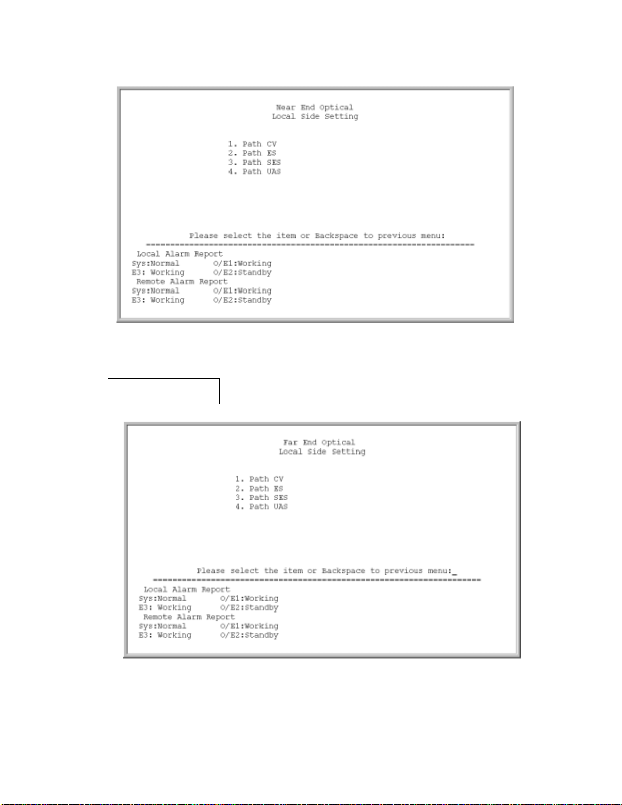
* Near End Optical:
Code Violation (CV)
Errored Second (ES)
Severely Errored Second (SES)
Unavailable Second (UAS)
* Far End Optical:
Code Violation (CV)
Errored Second (ES)
Severely Errored Second (SES)
Unavailable Second (UAS)
z Storing System Parameters
E3FOM contains at least 2 Megabytes of SDRAM, enough for collecting system
parameters at a 15-minute interval, 24 hours a day for 7 days. E3FOM can store
different types of system parameters, including the CV, ES, SES, UAS values for local and
remote optics and electric signals.
z Threshold Setting
To set the E3 threshold values for CV, ES, SES, and UAS, select option 6: PM Threshold
Setting.
Page 21

17
4-6 Network Management Function
E3FOM includes the network management function using SNMP protocol:
z EOC (Embedded Operation Channel):
▪ Monitoring the status of a remote E3FOM unit
▪ Able to be used to perform the Loopback tests
z Utilizes PPP (with the RJ45-to-DB9 converter, RS232 interface) port to provide
remote control by dial-up modem
z Utilizes LAN (Ethernet interface) port to provide remote control through the TCP/IP
Network
z Enterprise MIB files including with E3FOM:
▪ E3FOM SNMP MIB Management Objects
- System Configuration
systemConfig OBJECT-TYPE
sysNodeIndex OBJECT-TYPE
sysProfile OBJECT-TYPE
sysE3Lbo OBJECT-TYPE
sysOeSwitch OBJECT-TYPE
sysOeLocked OBJECT-TYPE
sysLloopback OBJECT-TYPE
sysRloopback OBJECT-TYPE
sysRequestRlb OBJECT-TYPE
hostIpAddress OBJECT-TYPE
sysSignalFrame OBJECT-TYPE
-PM threshould value set
thresholdTable OBJECT-TYPE
thNodeIndex OBJECT-TYPE
E3thBPVmin OBJECT-TYPE
E3thBPVDay OBJECT-TYPE
E3thBESmin OBJECT-TYPE
E3thBESHour OBJECT-TYPE
E3thBESDay OBJECT-TYPE
E3thSESmin OBJECT-TYPE
E3thSESHour OBJECT-TYPE
E3thSESDay OBJECT-TYPE
E3thUASmin OBJECT-TYPE
E3thUASHour OBJECT-TYPE
Page 22

18
E3thUASDay OBJECT-TYPE
onethCVmin OBJECT-TYPE
onethCVHour OBJECT-TYPE
onethCVDay OBJECT-TYPE
onethESmin OBJECT-TYPE
onethESHour OBJECT-TYPE
onethESDay OBJECT-TYPE
onethSESmin OBJECT-TYPE
onethSESHour OBJECT-TYPE
onethSESDay OBJECT-TYPE
onethUASmin OBJECT-TYPE
onethUASHour OBJECT-TYPE
onethUASDay OBJECT-TYPE
ofethCVmin OBJECT-TYPE
ofethCVHour OBJECT-TYPE
ofethCVDay OBJECT-TYPE
ofethESmin OBJECT-TYPE
ofethESHour OBJECT-TYPE
ofethESDay OBJECT-TYPE
ofethSESmin OBJECT-TYPE
ofethSESHour OBJECT-TYPE
ofethSESDay OBJECT-TYPE
ofethUASmin OBJECT-TYPE
ofethUASHour OBJECT-TYPE
ofethUASDay OBJECT-TYPE
- Current PM report
E3 interface
E3pmcurrent OBJECT-TYPE
E3pmCurrentNodeIndex OBJECT-TYPE
E3pmCurrentBPV OBJECT-TYPE
E3pmCurrentBES OBJECT-TYPE
E3pmCurrentSES OBJECT-TYPE
E3pmCurrentUAS OBJECT-TYPE
Page 23

19
Optical interface
oNEpmcurrent OBJECT-TYPE
oNEpmCurrentNodeIndex OBJECT-TYPE
oNEpmCurrentCV OBJECT-TYPE
oNEpmCurrentES OBJECT-TYPE
oNEpmCurrentSES OBJECT-TYPE
oNEpmCurrentUAS OBJECT-TYPE
oFEpmcurrent OBJECT-TYPE
oFEpmCurrentNodeIndex OBJECT-TYPE
oFEpmCurrentCV OBJECT-TYPE
oFEpmCurrentES OBJECT-TYPE
oFEpmCurrentSES OBJECT-TYPE
oFEpmCurrentUAS OBJECT-TYPE
- 15min interval PM report
E3 interface
E3pm15min OBJECT-TYPE
E3pm15minNode OBJECT-TYPE
E3pm15minNumber OBJECT-TYPE
E3pm15minBPV OBJECT-TYPE
E3pm15minBES OBJECT-TYPE
E3pm15minSES OBJECT-TYPE
E3pm15minUAS OBJECT-TYPE
Optical interface
oNEpm15min OBJECT-TYPE
oNEpm15minNode OBJECT-TYPE
oNEpm15minNumber OBJECT-TYPE
oNEpm15minCV OBJECT-TYPE
oNEpm15minES OBJECT-TYPE
oNEpm15minSES OBJECT-TYPE
oNEpm15minUAS OBJECT-TYPE
oFEpm15min OBJECT-TYPE
oFEpm15minNode OBJECT-TYPE
oFEpm15minNumber OBJECT-TYPE
oFEpm15minCV OBJECT-TYPE
oFEpm15minES OBJECT-TYPE
oFEpm15minSES OBJECT-TYPE
oFEpm15minUAS OBJECT-TYPE
- Day interval PM report
Page 24

20
E3 interface
E3pmDay OBJECT-TYPE
E3pmDayNode OBJECT-TYPE
E3pmDayNumber OBJECT-TYPE
E3pmDayBPV OBJECT-TYPE
E3pmDayBES OBJECT-TYPE
E3pmDayCV OBJECT-TYPE
E3pmDayES OBJECT-TYPE
E3pmDaySES OBJECT-TYPE
E3pmDayUAS OBJECT-TYPE
Optical interface
oNEpmDay OBJECT-TYPE
oNEpmDayNode OBJECT-TYPE
oNEpmDayNumber OBJECT-TYPE
oNEpmDayCV OBJECT-TYPE
oNEpmDayES OBJECT-TYPE
oNEpmDaySES OBJECT-TYPE
oNEpmDayUAS OBJECT-TYPE
oFEpmDay OBJECT-TYPE
oFEpmDayNode OBJECT-TYPE
oFEpmDayNumber OBJECT-TYPE
oFEpmDayCV OBJECT-TYPE
oFEpmDayES OBJECT-TYPE
oFEpmDaySES OBJECT-TYPE
oFEpmDayUAS OBJECT-TYPE
Page 25

21
4-7 Craft Port Operation
Craft port allows users to monitor and configure E3FOM through a local terminal
emulator, such as VT100.
Note: Options 5, 6, 7, 8 from the Menu Tree are not accesible from the LCD front pannel
5: PM Status Report
6: PM Threshold Setting
7: Agent Network Configuration
8: System Information
4-8 Connect and Setup the Craft Port
z Connects the craft port to a local terminal using DB-9 cable.
z VT100 terminal settings:
Bit Rate: 9600bps
Data Bit: 8 bit
Parity: No Parity
Stop Bit: 1 Stop bit
Set the emulation mode to”VT100” or “Auto Detect”.
4-9 Operating Fr om the Craft Port
After properly connecting the craft port to a terminal, the system will prompt the users for
password. The universal password is “URDR. or 1234”
Page 26

22
The figure below is a screenshot of the login terminal screen:
Users can access a function by typing its corresponding number into the local terminal.
To go back to the previous menu, press the ‘Backspace” key. Refer to the Menu Tree for
navigation.
E3FOM V1.0
Page 27

23
After entering the local terminal screen, user can select Local Side operation and
Remote Side operation for configuration, loopback, and monitoring of the E3FOM.
Local/Remote
E3 FOM V1.0
Page 28

24
After entering the main menu, select one of the following nine functions:
1. Profile
2. Configuration
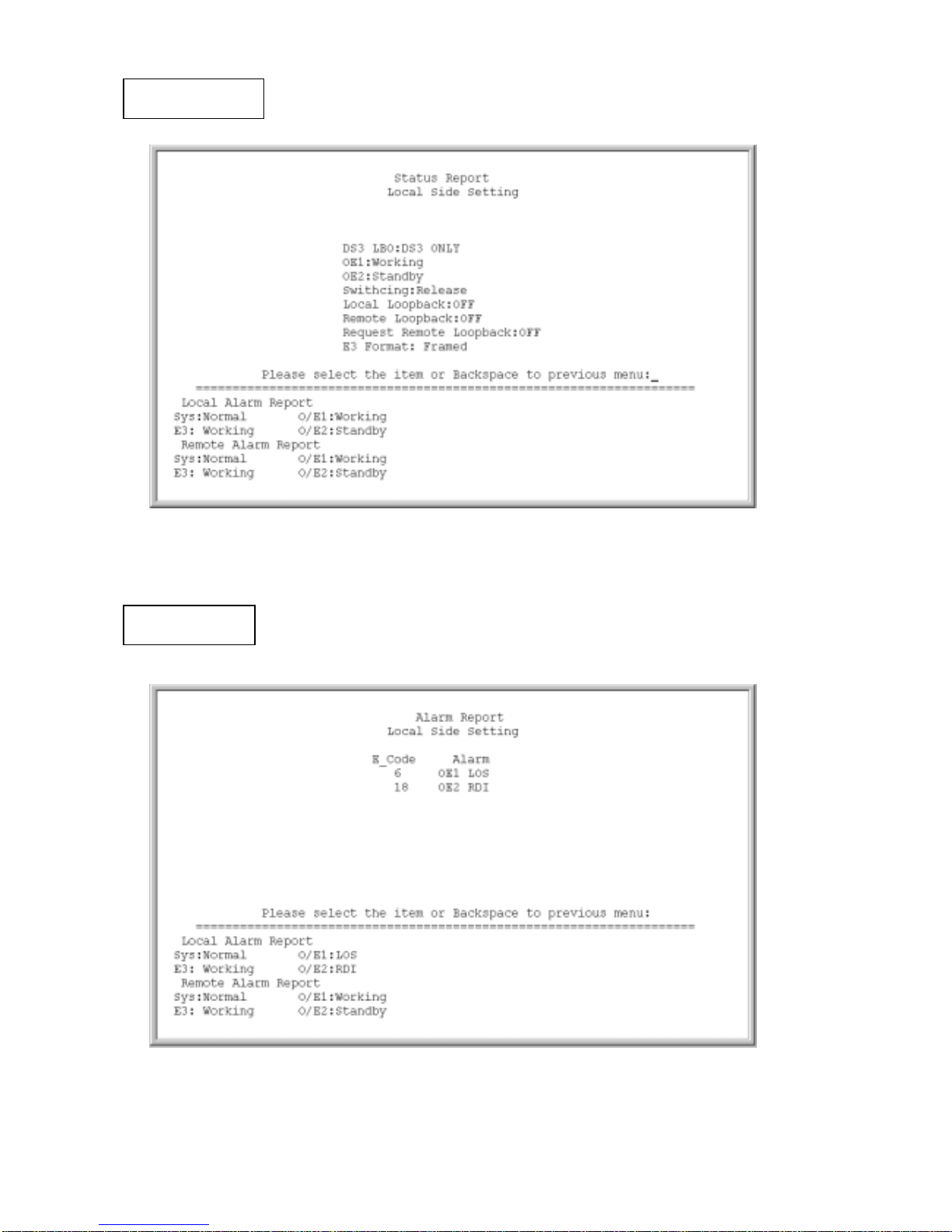
3. Status Report
4. Alarm Report
5. PM Status Report
6. PM Threshold Setting
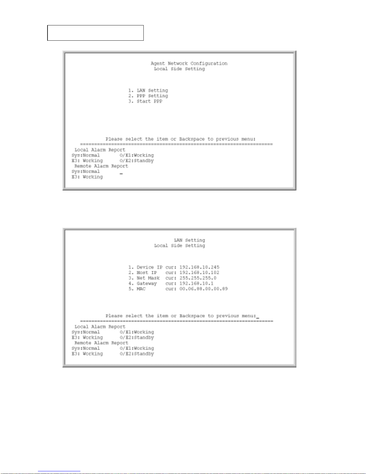
7. Agent Network Configuration
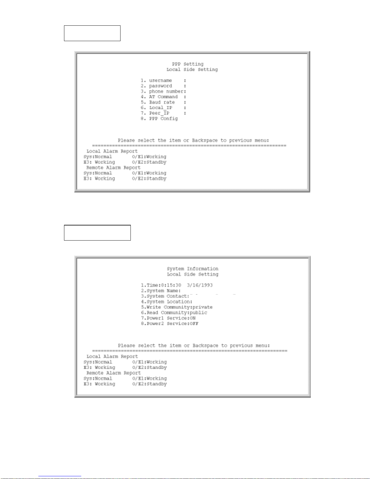
8. System Information
Main Menu
Page 29
25
\
E3 configuration
Profile
Page 30
26
Status Report
Alarm Report
Page 31
27
PM Report
PM Current Report
Page 32
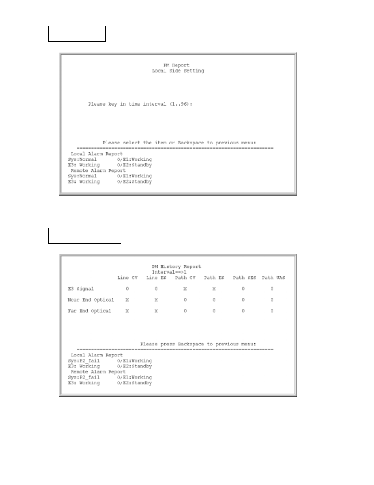
28
PM Report
PM History Report
Page 33
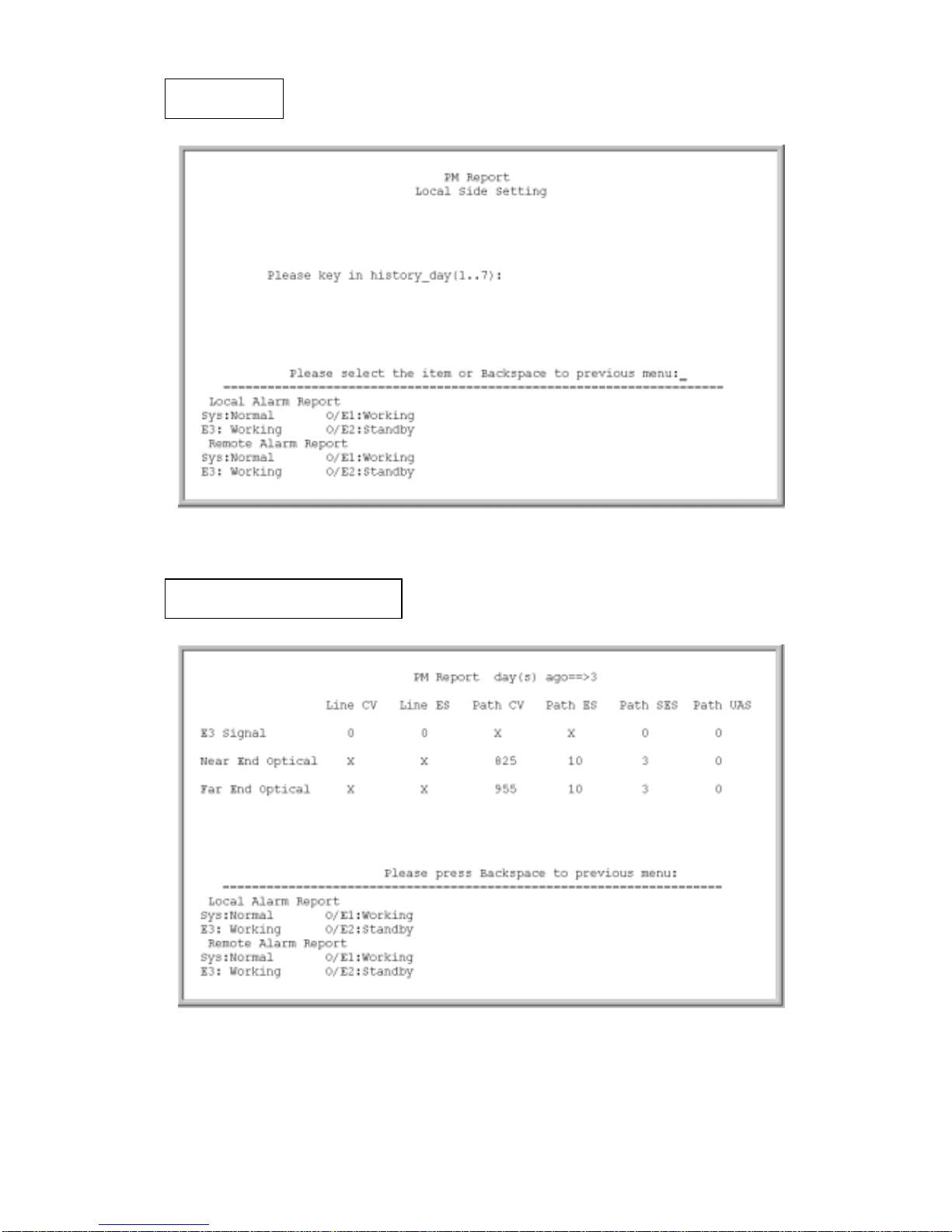
29
PM Report
PM Report day(s) ago==>1
Page 34
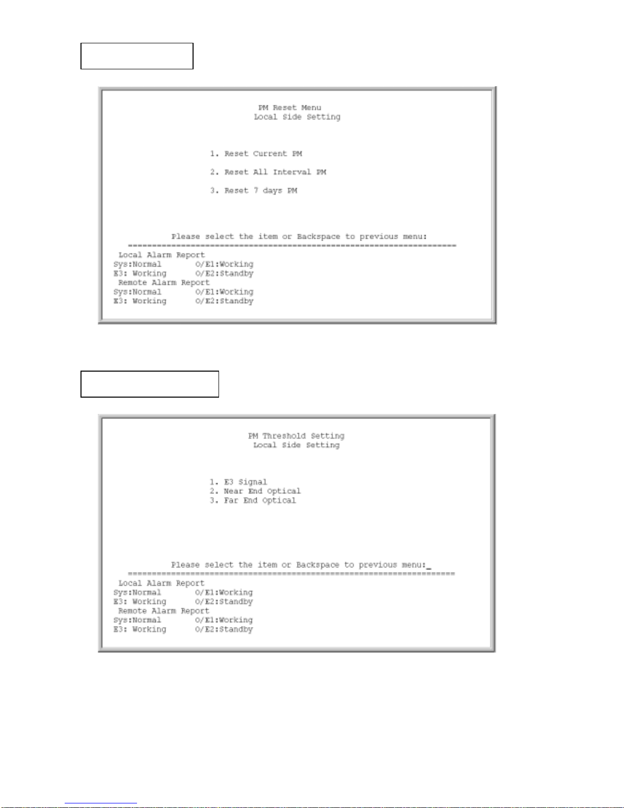
30
PM Reset Menu
PM Threshold Setting
Page 35
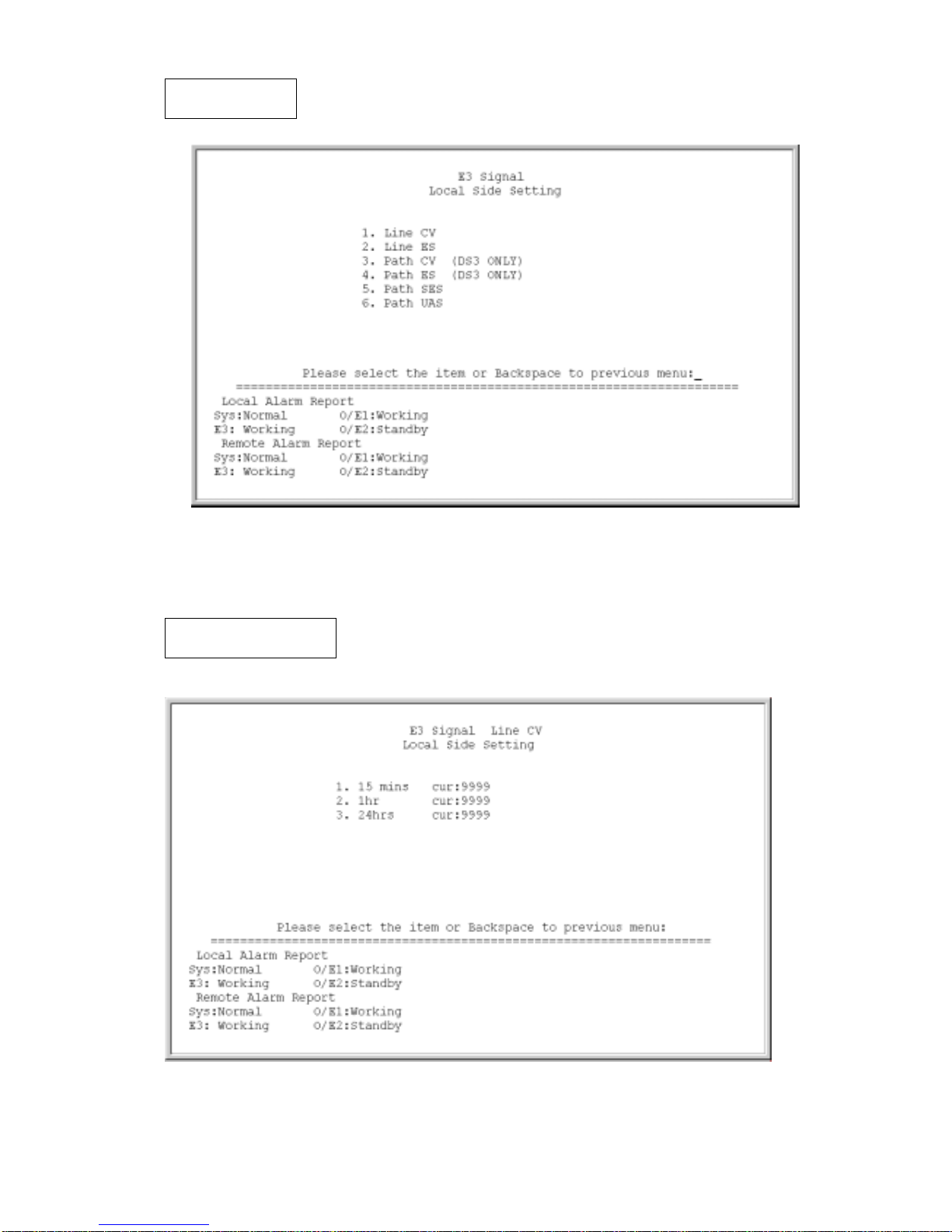
31
E3 Signal
E3 Signal Line CV
Page 36
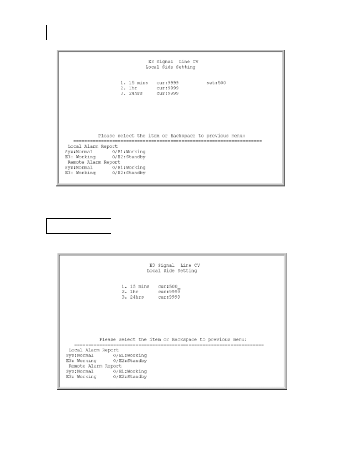
32
E3 Signal Line CV
E3 Signal Line CV
Page 37
33
Near End Optical
Far End Optical
Page 38
34
Agent Network Configuration
Page 39
35
PPP Setting
Near-end Setting
E3 FOM
Page 40
36
Chapter 5 Diagnostics and Loopback Functions
5-1 General Information
This chapter contains detailed information on the diagnostics and the loopback tests of
the E3FOM fiber optics transmission equipment. Users can activate the loopback function
to diagnose the full service.
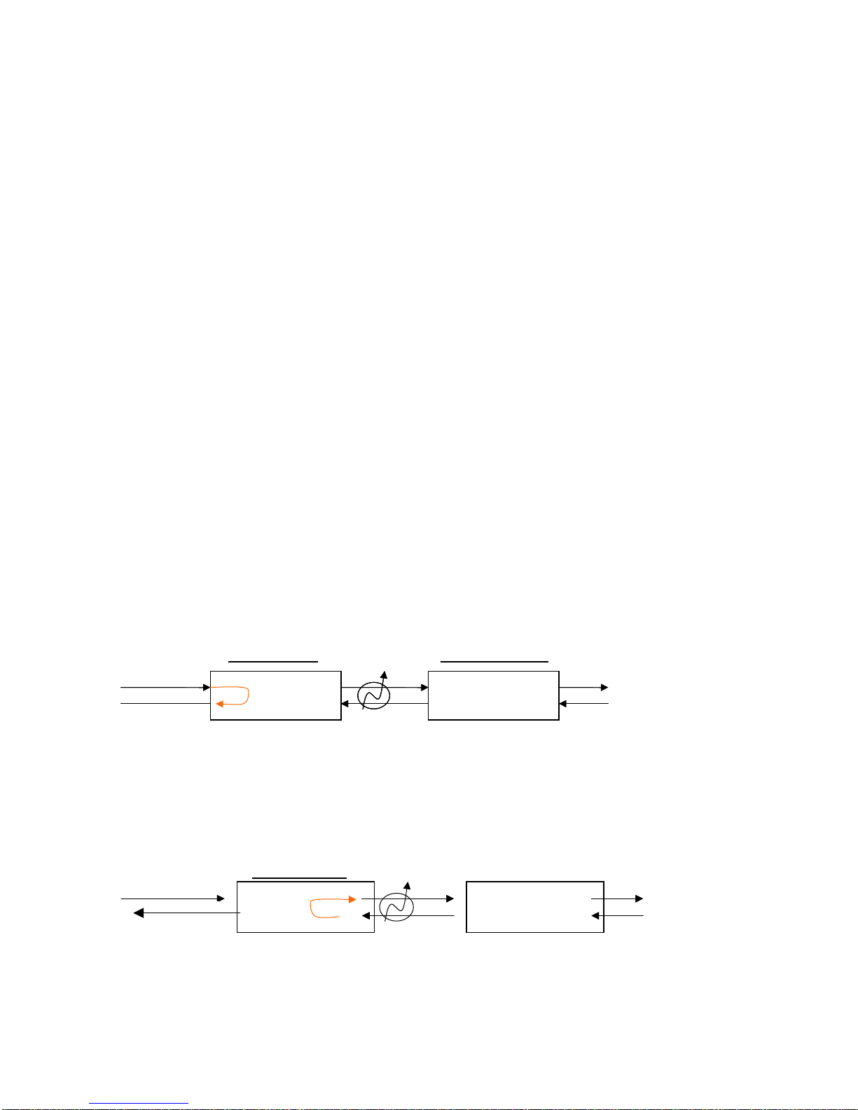
5-2 Loopback Functions
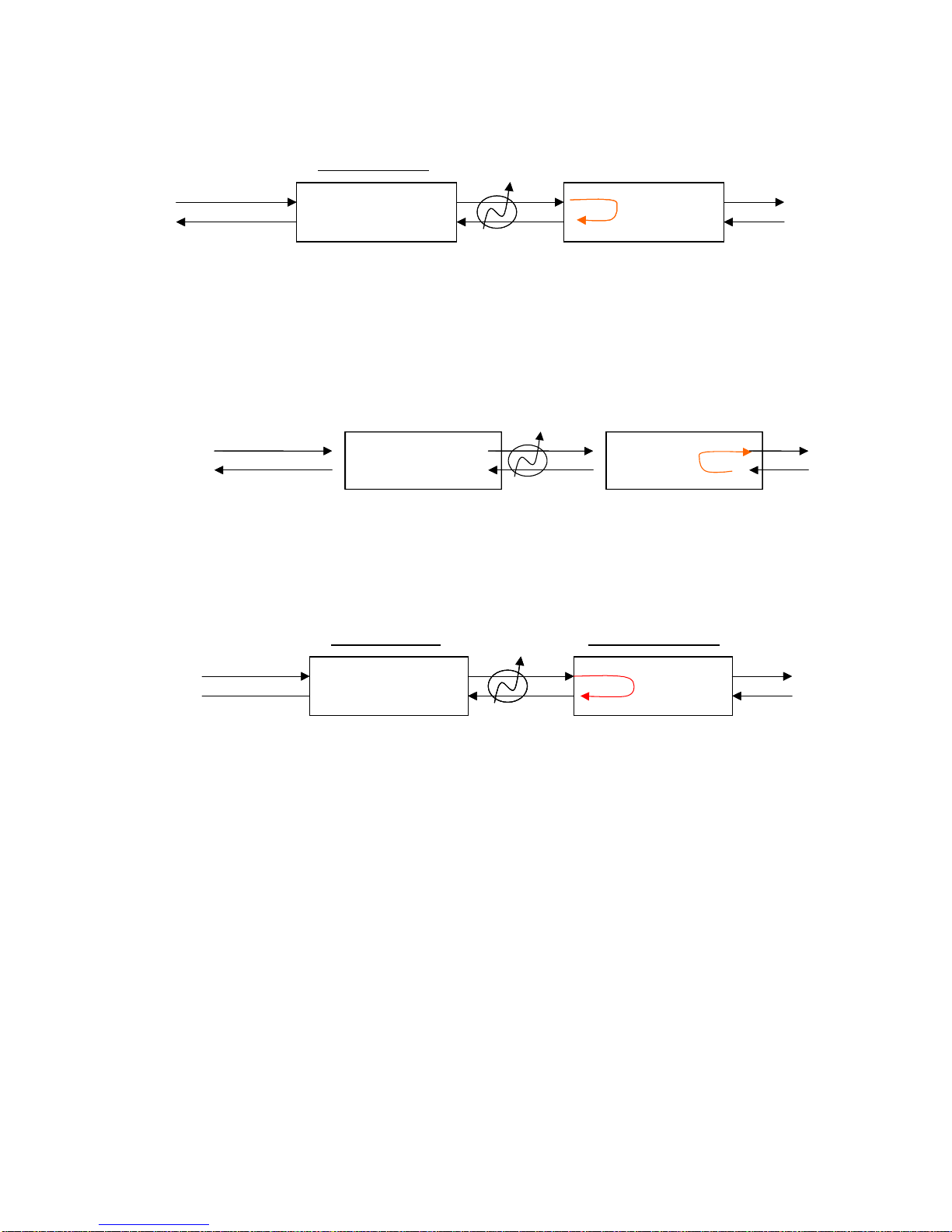
There are three types of loopback functions for the E3FOM: Local Loopback, Remote
Loopback and Request Remote Loopback. User can perform the loopback test under the
“System Configurations” option.
Figures below illustrate the concepts of the loopback function:
z Local Side Loopback:
Local Side Loopback tests the path between local E3FOM and the remote one.
1. Local Loopback
2. Remote Loopback
Local side
Remote side
Local side
Remote side
E3 AIS
Optical AIS
Local side Remote side
E3AIS
Page 41
37
3. Request Remote Loopback
z Remote side:
z Remote Side Loopback:
1. Local loopback
2. Remote Loopback
Local side Remote side
E3 AIS
Remote side
E3 AIS
Local Side
Remote si
de
Local si
de
E3 AIS
Page 42

E3FOM-LOE
 Loading...