

Page 1

DeviceMaster® EIP-MOD
EtherNet®/IP - Modbus®
User Guide
Page 2

Trademark Notices
Document Number: 2000664 Rev A
Comtrol, DeviceMaster, and PortVision are trademarks owned by Pepperl + Fuchs, GmbH and are used
under license by Pepperl + Fuchs Comtrol, Inc.
Concept is a trademark of Schneider Electric.
Modbus is a registered trademark of Schneider Electric.
ControlLogix, PLC-5 and Rockwell Automation are registered trademarks of Rockwell Automation.
MicroLogix, RSLinx, RSLogix 5, RSLogix 500, RSLogix 5000 and SLC are trademarks of Rockwell
Automation.
PLC is a registered trademark of Allen-Bradley Company, Inc.
Ethernet is a registered trademark of Digital Equipment Corporation, Intel, and Xerox Corporation.
Portions of the web interface are copyrighted by GoAhead Software, Inc. Copyright © 2001. GoAhead
Software, Inc. All Rights Reserved.
Windows is a registered trademark of Microsoft Corporation in the United States and/or other countries.
Other product names mentioned herein may be trademarks and/or registered trademarks of their respective
owners.
First Edition, April 3, 2019
Copyright © 2019. Pepperl + Fuchs Comtrol, Inc.
All Rights Reserved.
Pepperl + Fuchs Comtrol, Inc. makes no representations or warranties with regard to the contents of this
document or to the suitability of the Pepperl + Fuchs Comtrol, Inc. product for any particular purpose.
Specifications subject to change without notice. Some software or features may not be available at the time of
publication. Contact your reseller for current product information.
Page 3

Table of Contents
Chapter 1. Introduction........................................................................................................7
1.1. EtherNet/IP-Modbus Gateway Overview.......................................................................................... 7
1.2. System Architecture .............................................................................................................................. 9
1.3. EtherNet/IP to Modbus Translation Layer Architecture............................................................ 10
1.4. Translation Layer Connections ........................................................................................................ 11
1.4.1. Connection Methods Table............................................................................................................. 11
1.4.2. EtherNet/IP Controllers Class1 to/from Shared Memory ............................................................ 12
1.4.3. EtherNet/IP Controllers via Data Mapping to/from Tag/File ...................................................... 12
1.4.4. EtherNet/IP Controllers CIP Modbus Object via MSG Instructions........................................... 13
1.5. Data Type Definitions ......................................................................................................................... 13
1.5.1. Terms and Definitions .................................................................................................................... 14
1.6. What is Modbus? ................................................................................................................................... 16
1.6.1. Modbus/RTU ................................................................................................................................... 16
1.6.2. Modbus/ASCII................................................................................................................................. 17
1.6.3. Modbus/TCP.................................................................................................................................... 18
1.7. Locating the Latest Software and Documentation ...................................................................... 19
Chapter 2. EtherNet/IP Interface Profile (ControlLogix)...........................................21
2.1. Modbus Object (44 Hex, 1 Instance) ................................................................................................. 21
2.1.1. Class Attributes .............................................................................................................................. 21
2.1.2. Instance Attributes......................................................................................................................... 21
2.1.3. Common Services............................................................................................................................ 21
2.1.4. Object Specific Services (Instance Specific) .................................................................................. 22
2.1.4.0.1. Read Discrete Inputs Service (4B Hex)..................................................................................................22
2.1.4.0.2. Read Coils Service (4C Hex)....................................................................................................................22
2.1.4.0.3. Read Input Registers Service (4D Hex)..................................................................................................22
2.1.4.0.4. Read Holding Registers Service (4E Hex)..............................................................................................23
2.1.4.0.5. Write Coils Service (4F Hex)...................................................................................................................23
2.1.4.0.6. Write Holding Registers Service (50 Hex)..............................................................................................23
2.1.4.0.7. Modbus Passthrough Service (51 Hex)...................................................................................................23
2.1.4.0.8. Vendor Specific Write Single Coil Service (70 Hex)...............................................................................23
2.1.4.0.9. Vendor Specific Write Single Register Service (71 Hex) .......................................................................23
2.1.4.0.10. Vendor Specific Write Mask Register (72 Hex)....................................................................................23
2.1.4.0.11. Vendor Specific Read/Write Holding Registers (73 Hex) ....................................................................24
2.2. Informational Objects ......................................................................................................................... 24
2.2.1. Identity Object (01 Hex, 1 Instance).............................................................................................. 24
2.2.1.1. Class Attributes .................................................................................................................... 24
2.2.1.2. Instance Attributes ............................................................................................................... 24
2.2.1.3. Status Word........................................................................................................................... 25
2.2.1.4. Common Services .................................................................................................................. 26
2.2.2. Message Router Object (02 Hex).................................................................................................... 27
2.2.2.1. Class Attributes .................................................................................................................... 27
2.2.2.2. Instance Attributes ............................................................................................................... 27
2.2.2.3. Common Services .................................................................................................................. 27
2.2.3. Connection Manager Object (06 Hex) ............................................................................................ 28
2.2.3.1. Class Attributes Object (06 hex) .......................................................................................... 28
2.2.3.2. Instance Attributes (06 hex)................................................................................................. 28
2.2.3.3. Common Services Object (06 hex) ........................................................................................28
2.2.4. Port Object (F4 Hex - 1 Instance) .................................................................................................. 29
2.2.4.1. Class Attributes .................................................................................................................... 29
2.2.4.2. Instance Attributes (F4 Hex, Instance 1) ............................................................................ 29
2.2.4.3. Instance Attributes (F4 Hex, Instance 2) ............................................................................ 30
DeviceMaster EIP-MOD User Guide: 2000664 Rev. A Table of Contents - 3
Page 4

2.2.4.4. Common Services .................................................................................................................. 31
2.2.5. TCP Object (F5 Hex - 1 Instance) .................................................................................................. 31
2.2.5.1. Class Attributes .................................................................................................................... 31
2.2.5.2. Instance Attributes ............................................................................................................... 31
2.2.5.3. Common Services .................................................................................................................. 33
2.2.6. Ethernet Link Object (F6 Hex) ...................................................................................................... 33
2.2.6.1. Class Attributes .................................................................................................................... 33
2.2.6.2. Instance Attributes ............................................................................................................... 34
2.2.6.3. Common Services .................................................................................................................. 35
2.2.7. Assembly Object (For Class 1 Interface) ....................................................................................... 35
2.2.7.1. Class Attributes .................................................................................................................... 35
2.2.7.2. Instance Attributes ............................................................................................................... 35
2.2.7.2.1. Instance Attribute Definitions: Attribute 3-Request/Write Data.........................................................36
2.2.7.2.2. Instance Attribute Definitions: Attribute 4-Data Length.....................................................................36
2.2.7.3. Common Services .................................................................................................................. 36
2.2.7.4. Instance Definitions .............................................................................................................. 36
2.2.7.4.1. Instance Definitions (Default).................................................................................................................36
2.2.7.4.2. All Available Instance Definitions..........................................................................................................37
Chapter 3. Configuration Overview ................................................................................41
3.1. Home Page ............................................................................................................................................. 41
3.2. Serial Port - Configuration Overview ............................................................................................. 43
3.3. Modbus Over TCP Overview - Configuration Overview............................................................. 45
Chapter 4. Serial Menus .....................................................................................................47
4.1. Serial Port Overview Page................................................................................................................. 47
4.2. Serial Port Configuration Page ........................................................................................................ 48
Chapter 5. Modbus Menus..................................................................................................53
5.1. Modbus over TCP (not Modbus/TCP) Overview ........................................................................... 53
5.2. Modbus over TCP (not Modbus/TCP) Socket Configuration Page ........................................... 54
5.3. Modbus/TCP Configuration Page ..................................................................................................... 56
5.4. Remote Modbus/TCP Device Configuration .................................................................................. 57
5.5. Modbus Alias Configuration .............................................................................................................. 59
Chapter 6. Network Menus ................................................................................................61
6.1. Network Configuration Page............................................................................................................. 61
6.2. Password Page ...................................................................................................................................... 63
6.3. Security Settings Page ........................................................................................................................ 64
6.4. Key and Certificate Management Page........................................................................................... 65
6.5. EtherNet/IP Stack Configuration ..................................................................................................... 67
Chapter 7. Data Mapping Menus ......................................................................................69
7.1. Modbus to EtherNet/IP Tag/File Configuration Page ................................................................. 69
7.2. EtherNet/IP Tag/File to Modbus Configuration Page ................................................................. 72
7.3. Modbus to Modbus Configuration Page.......................................................................................... 75
7.4. Shared Memory Configuration Page ............................................................................................... 78
7.5. EtherNet/IP Class 1 Page.................................................................................................................... 83
7.5.1. Active Class1 Interface Page ......................................................................................................... 83
7.5.2. All Shared Memory Class1 Interface Page ................................................................................... 84
7.6. Data Mapping Verification Page ...................................................................................................... 85
7.7. Shared Memory Map Page ................................................................................................................. 87
4 - Table of Contents DeviceMaster EIP-MOD User Guide: 2000664 Rev. A
Page 5

Chapter 8. Diagnostic Menus ............................................................................................91
8.1. Serial Communication Statistics Page ............................................................................................ 92
8.2. Modbus RTU/ASCII over Ethernet TCP Statistics Page ............................................................. 94
8.3. Serial Interface Logs ........................................................................................................................... 96
8.4. Known Modbus Slave Device List .................................................................................................... 97
8.5. Modbus/TCP and Serial Modbus Master Statistics Page .......................................................... 100
8.6. Modbus/TCP Connections Page ...................................................................................................... 104
8.7. Modbus Alias Device ID Statistics Page ....................................................................................... 106
8.8. Shared Memory Contents ................................................................................................................. 107
8.8.1. Shared Holding Block Register Blocks ........................................................................................ 107
8.8.2. Shared Coil Blocks........................................................................................................................ 109
8.9. Ethernet/IP Interface Statistics Page ........................................................................................... 111
8.10. Modbus to EtherNet/IP Tag/File Diagnostics Page.................................................................. 113
8.11. EtherNet/IP Tag/File to Modbus Diagnostics Page.................................................................. 115
8.12. Modbus to Modbus Diagnostics Page .......................................................................................... 116
8.13. System Log ......................................................................................................................................... 118
Chapter 9. System Menus .................................................................................................119
9.1. Update Firmware ............................................................................................................................... 119
9.2. Configuration File Page.................................................................................................................... 121
9.2.1. Saving a Configuration File ......................................................................................................... 121
9.2.2. Loading a Configuration File ....................................................................................................... 122
9.3. System Snapshot Page ...................................................................................................................... 123
9.4. Restore Defaults Page ....................................................................................................................... 124
9.5. Reboot ................................................................................................................................................... 125
Chapter 10. PLC Programming for Modbus Object (44 Hex)...................................127
10.1. Read Discrete Inputs Service (4B Hex)....................................................................................... 127
10.2. Read Coils Service (4C Hex) .......................................................................................................... 129
10.3. Read Input Registers Service (4D Hex) ...................................................................................... 131
10.4. Read Holding Registers Service (4E Hex) .................................................................................. 133
10.5. Write Coils Service (4F Hex).......................................................................................................... 135
10.6. Write Holding Registers Service (50 Hex) ..................................................................................137
10.7. Vendor Specific Write Single Coil Service (70 Hex)................................................................. 141
10.8. Vendor Specific Write Single Register Service (71 Hex) ........................................................ 143
10.9. Vendor Specific Write Mask Register (72 Hex) ......................................................................... 145
10.10. Vendor Specific Read/Write Holding Registers (73 Hex)...................................................... 148
Chapter 11. Class 1 Interface Definition.......................................................................151
11.1. Configuring an I/O Ethernet Module on a ControlLogix PLC............................................... 151
Chapter 12. Troubleshooting and Technical Support ...............................................155
12.1. Troubleshooting Checklist ............................................................................................................ 155
12.2. General Troubleshooting ............................................................................................................... 156
12.3. Daisy-Chaining DeviceMaster EIP-MOD Units With Two Ethernet Ports ......................... 157
12.4. Technical Support............................................................................................................................ 158
DeviceMaster EIP-MOD User Guide: 2000664 Rev. A Table of Contents - 5
Page 6

6 - Table of Contents DeviceMaster EIP-MOD User Guide: 2000664 Rev. A
Page 7

Chapter 1. Introduction
This document describes how to configure the DeviceMaster EIP-MOD for the EtherNet/IP-Modbus after
basic DeviceMaster EIP-MOD installation and configuration procedures.
• EtherNet/IP Interface Profile (ControlLogix)
• Configuration Overview
• Serial Menus
• Modbus Menus
• Network Menus
• Diagnostic Menus
• System Menu
See Locating the Latest Software and Documentation
and tools.
on Page 47
on Page 53
on Page 61
s on Page 119
on Page 41
on Page 91
1.1. EtherNet/IP-Modbus Gateway Overview
The DeviceMaster EtherNet/IP-Modbus gateway provides the following functionality.
EtherNet/IP interface support:
• Supports all fully CIP compliant controllers including Rockwell ControlLogix, CompactLogix, SoftLogix,
Schneider Electric, Omron, and GE PLCs, OPC Servers, SCADA systems, HMIs and many more.
• Supports PCCC based PLCs such as MicroLogix, SLC 5/05 and PLC-5.
• EtherNet/IP Interface specifics:
- Maximum CIP sessions = 128
- Maximum CIP input (to PLC) connections = 128
- Maximum CIP output (from PLC) connections = 16
- Write-to-Tag/File and Read-from-Tag/File support
- CIP Modbus Object support. Custom service codes support additional Modbus function codes.
• EtherNet/IP controllers can communicate to:
• Shared Memory
• A wide variety of Modbus slave devices:
- Local serial Modbus/RTU and Modbus/ASCII slave devices
- Modbus/TCP slaves
- Remote serial Modbus/RTU and Modbus/ASCII devices connected to other gateways
• A wide variety of Modbus masters via Shared Memory:
- Modbus/TCP masters
- Modbus/RTU and Modbus/ASCII masters over Ethernet TCP connections
- Serial Modbus/RTU and Modbus/ASCII masters
• Other EtherNet/IP controllers via Shared Memory
- Via Class1 connections to Shared memory
- CIP Modbus Object messages
on Page 21
on Page 19 to locate the latest firmware, documentation,
DeviceMaster EIP-MOD User Guide: 2000664 Rev. A Chapter 1. Introduction - 7
Page 8

EtherNet/IP-Modbus Gateway Overview
- Via Read-from-Tag/File and Write-to-File/Tag configurations
The most extensive Modbus functionality in the industry:
• Up to 96 Modbus/TCP connections
• Support up to eight unique Modbus TCP socket port numbers. (i.e. 502, 503, 505, etc.)
• Multiple Modbus/RTU and/or Modbus/ASCII over Ethernet TCP connections
• Local serial Modbus/RTU and Modbus/ASCII slave devices
• Maximum sized Modbus messages
• Serial Modbus/RTU and Modbus/ASCII masters
• Shared Memory that can be configured to provide communication interfaces between a vast array of
Modbus slaves, Modbus masters and EtherNet/IP controllers.
• Modbus Alias functionality
• Remote Modbus device connectivity
• Modbus slave to Modbus slave communication
• Private Modbus serial bus connectivity – A serial port connected to a serial master and one or more serial
slave devices
A Data Mapping process that provides:
• EtherNet/IP Tag/File to Modbus connectivity - to either Modbus device(s) or Shared memory
• Modbus to EtherNet/IP Tag/File connectivity - from either Modbus device(s) or Shared memory
• Modbus to Modbus connectivity
- Can read from multiple Modbus devices into Shared Memory.
- Can write from Shared memory to multiple Modbus devices.
- Can read directly from one Modbus slave device to another Modbus slave device anywhere on the
Modbus network. These devices can be of any supported type, local or remote.
- Can convert from Modbus register type to another automatically.
• A Data Mapping verification web page that checks for possible Modbus write conflicts, incorrect
configuration and write violations.
• A Shared Memory map web page that displays the Shared Memory read and write memory blocks as
defined utilized by the Data Mapping.
8 - Chapter 1. Introduction DeviceMaster EIP-MOD User Guide: 2000664 Rev. A
Page 9

1.2. System Architecture
The DeviceMaster EtherNet/IP-Modbus firmware utilizes the following architecture.
System Architecture
The firmware architecture is designed to take full advantage of a broad range of EtherNet/IP and Modbus
routing functionality supported by the DeviceMaster EtherNet/IP-Modbus gateway.
DeviceMaster EIP-MOD User Guide: 2000664 Rev. A Chapter 1. Introduction - 9
Page 10
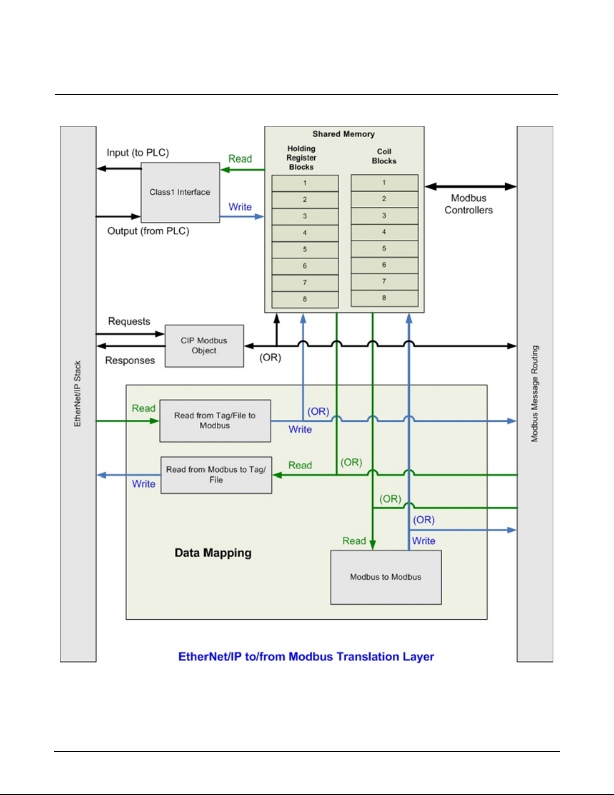
EtherNet/IP to Modbus Translation Layer Architecture
1.3. EtherNet/IP to Modbus Translation Layer Architecture
The following image illustrates the EtherNet/IP to/from Modbus translation layer.
10 - Chapter 1. Introduction DeviceMaster EIP-MOD User Guide: 2000664 Rev. A
Page 11

Translation Layer Connections
1.4. Translation Layer Connections
The following connections are possible through the translation layer.
1.4.1. Connection Methods Table
This table lists the possible connections and the methods available for a wide variety of EtherNet/IP and
Modbus interfaces.
Write (To)
via Tag/File
Class1 Connection
EtherNet/IP PLC(s) via
EtherNet/IP PLC(s) via
Class1 Connection
EtherNet/IP PLC(s) via Tag/
File
EtherNet/IP PLC(s) via
Modbus Object
Modbus/TCP Master(s)2322221,31,31,3
Modbus RTU/ASCII Serial
Master(s)
Modbus RTU/ASCII Over
Ethernet TCP Master(s)
Read (From)
Modbus RTU/ASCII Serial
Slave(s)
Modbus/TCP Slave(s) 3 3,4 1,3 1,3 1,3 1,3 3,4 3,4 3,4
Remote Modbus RTU/ASCII
Serial Slave(s)
Where the method is:
1 = via direct message to Modbus slave device
2 = via Shared Memory
3 = via Shared Memory and use of Data Mapping
4 = via use of only Data Mapping
232222333
3333333,43,43,4
2322221,31,31,3
2322221,31,31,3
2322221,31,31,3
3 3,4 1,3 1,3 1,3 1,3 3,4 3,4 3,4
3 3,4 1,3 1,3 1,3 1,3 3,4 3,4 3,4
EtherNet/IP PLC(s)
via Modbus Object
EtherNet/IP PLC(s)
Modbus/TCP Master(s)
Serial Master(s)
Modbus RTU/ASCII
Modbus RTU/ASCII
Over Ethernet TCP Master(s)
Serial Slave(s)
Modbus RTU/ASCII
Serial Slave(s)
Modbus/TCP Slave(s)
Remote Modbus RTU/ASCII
DeviceMaster EIP-MOD User Guide: 2000664 Rev. A Chapter 1. Introduction - 11
Page 12

EtherNet/IP Controllers Class1 to/from Shared Memory
1.4.2. EtherNet/IP Controllers Class1 to/from Shared Memory
The following provides information about EtherNet/IP controllers Class1 to and from shared memory.
• Combined with the Data Mapping Modbus to Modbus functionality:
- Local serial Modbus/RTU and Modbus/ASCII slave devices.
- Remote serial Modbus/RTU and Modbus/ASCII slave devices (via additional gateways).
- Remote Modbus/TCP slaves.
• Modbus Controllers:
- Modbus/TCP masters
- Modbus/RTU and Modbus/ASCII over Ethernet TCP masters
- Serial Modbus/RTU and Modbus/ASCII masters
• Other EtherNet/IP controllers:
- Utilizing Class1 connections
- Combined with the Data Mapping Read Tag/File Write Modbus functionality
- Combined with the Data Mapping Read Modbus Write Tag/File functionality
1.4.3. EtherNet/IP Controllers via Data Mapping to/from Tag/File
The following provides information about EtherNet/IP controllers via data mapping to and from Tag/File.
• Directly to/from Modbus slave devices:
- Local serial Modbus/RTU and Modbus/ASCII slave devices.
- Remote serial Modbus/RTU and Modbus/ASCII slave devices (via additional gateways).
- Modbus/TCP slaves.
• Through Shared Memory:
- Combined with the Data Mapping Modbus to Modbus functionality:
- Local serial Modbus/RTU and Modbus/ASCII slave devices.
- Remote serial Modbus/RTU and Modbus/ASCII slave devices (via additional gateways).
- Remote Modbus/TCP slaves.
- Modbus Masters:
- Modbus/TCP masters
- Modbus/RTU and Modbus/ASCII over Ethernet TCP masters
- Serial Modbus/RTU and Modbus/ASCII masters
- Other EtherNet/IP controllers:
- Utilizing Class1 connection(s)
- Combined with the Data Mapping Read Tag/File Write Modbus functionality
- Combined with the Data Mapping Read Modbus Write Tag/File functionality
12 - Chapter 1. Introduction DeviceMaster EIP-MOD User Guide: 2000664 Rev. A
Page 13

EtherNet/IP Controllers CIP Modbus Object via MSG Instructions
1.4.4. EtherNet/IP Controllers CIP Modbus Object via MSG Instructions
The following provides information about EtherNet/IP controller CIP Modbus object via MSG instructions.
• Directly to/from Modbus slave devices:
- Local serial Modbus/RTU and Modbus/ASCII slave devices.
- Remote serial Modbus/RTU and Modbus/ASCII slave devices (via additional gateways).
- Modbus/TCP slaves.
• Through Shared Memory:
- Combined with the Data Mapping Modbus to Modbus functionality:
- Local serial Modbus/RTU and Modbus/ASCII slave devices.
- Remote serial Modbus/RTU and Modbus/ASCII slave devices (via additional gateways).
- Remote Modbus/TCP slaves.
- Modbus Masters:
- Modbus/TCP masters
- Modbus/RTU and Modbus/ASCII over Ethernet TCP masters
- Serial Modbus/RTU and Modbus/ASCII masters
- Other EtherNet/IP controllers:
- Utilizing Class1 connection(s)
- Combined with the Data Mapping Read Tag/File Write Modbus functionality
- Combined with the Data Mapping Read Modbus Write Tag/File functionality
1.5. Data Type Definitions
The following list defines the available data types.
Data Type Definition
USINT Unsigned short integer (8-bits)
UINT Unsigned integer (16-bit)
UDINT Unsigned double integer (32-bits)
INT Signed integer (16-bits)
DINT Signed double integer (32-bits)
BYTE Bit string (8-bits)
WORD Bit string (16-bits)
DWORD Bit string (32-bits)
STRING Character string (1-byte per character)
DeviceMaster EIP-MOD User Guide: 2000664 Rev. A Chapter 1. Introduction - 13
Page 14

Terms and Definitions
1.5.1. Terms and Definitions
This section uses the following terms and definitions.
Term Definition
Otherwise called implicit messaging, is a method of communication between
EtherNet/IP controllers and devices that:
Class 1
Class 3
EtherNet/IP
Ethernet TCP/IP
Ethernet UDP/IP
Multicast
Point-to-Point
Master (or Client)
Mode
Slave (or Server)
Mode
Device ID
Device ID Offset
Received Device ID The original device ID received in the Modbus message from a Modbus master.
Alias Device ID
Local Slave Device
Remote Slave
Device
• Uses Ethernet UDP messages.
• Is cyclic in nature. Input and/or output data is exchanged between the
controllers and devices at regular time intervals.
Otherwise called explicit messaging, is a method of communication between
EtherNet/IP controllers and devices that:
• Uses Ethernet TCP/IP messages.
• By itself is not cyclic in nature. The controller and devices must send
individual messages to each other.
An Ethernet based industrial communication protocol utilized to communicate
between controllers, often times PLCS, and devices.
Standard Ethernet communications protocol utilizing socket communication
interfaces that guarantees delivery to the intended device.
Standard Ethernet communications protocol utilizing socket communication
interfaces that does not guarantee delivery. The data may or may get to the
intended device.
Multicast addressing involves Ethernet devices sending messages to each other
using a multicast address. Multicast addressing:
• Uses a specified IP address range designated for multicast communication.
• Allows either one or multiple devices to receive the same messages.
Point-to-Point, otherwise called unicast, addressing involves Ethernet devices
sending messages directly to each other using their own IP addresses. Messages
are sent to only one device.
The method of operation when a PLC, a gateway, or an application is operating
as a Master or the message originator.
The method of operation when a PLC, a gateway, or an application is operating
as a Slave or the message receiver.
The Modbus device identification number. Device IDs include:
• 0 = Broadcast
• 1-247 = Standard device IDs
• 248-255 = Reserved device IDs (generally used for vendor specific gateway
functions)
An offset applied at the slave serial port interface that changes the message
device ID range to match the serial device(s) device ID range.
The device ID that the original received ID is changed to when an Alias Device
ID is configured.
A local slave device is one that is connected directly to a serial port on the
gateway.
A remote slave device is either a slave Modbus/TCP device or a serial slave
device attached to another gateway and accessed as a remote Modbus/TCP
device.
14 - Chapter 1. Introduction DeviceMaster EIP-MOD User Guide: 2000664 Rev. A
Page 15

Terms and Definitions
Term Definition (Continued)
The standard Modbus messages, in hexadecimal format, that are typically
transmitted over serial lines but can also be transmitted over other
Modbus/RTU
communication methods such as wireless or Ethernet TCP/IP socket
connections.
Note: Modbus/RTU over Ethernet TCP/IP is not the same as Modbus TCP.
Modbus/ASCII
An ASCII, or character based, form of Modbus. The base message is the same as
Modbus/RTU, but the format is somewhat different.
An Ethernet based form of Modbus communication. The base message is the
Modbus/TCP
same as Modbus/RTU, but a special Modbus header is included for packet
identification and routing purposes.
The process where a PLC or Application requests data on a continual basis. In
Polling
this operation the Master sends the request messages while the Slave responds
to the messages.
Ethernet TCP/IP A form of Ethernet connectivity that provides a level of guaranteed delivery and
data verification. This is used for many upper layer protocols such as Modbus/
TCP and can be also used for transferring Modbus/RTU and Modbus/ASCII.
messages.
DeviceMaster EIP-MOD User Guide: 2000664 Rev. A Chapter 1. Introduction - 15
Page 16
What is Modbus?
1.6. What is Modbus?
This subsection discusses:
•
Modbus/RTU
• Modbus/ASCII on Page 17
• Modbus/TCP
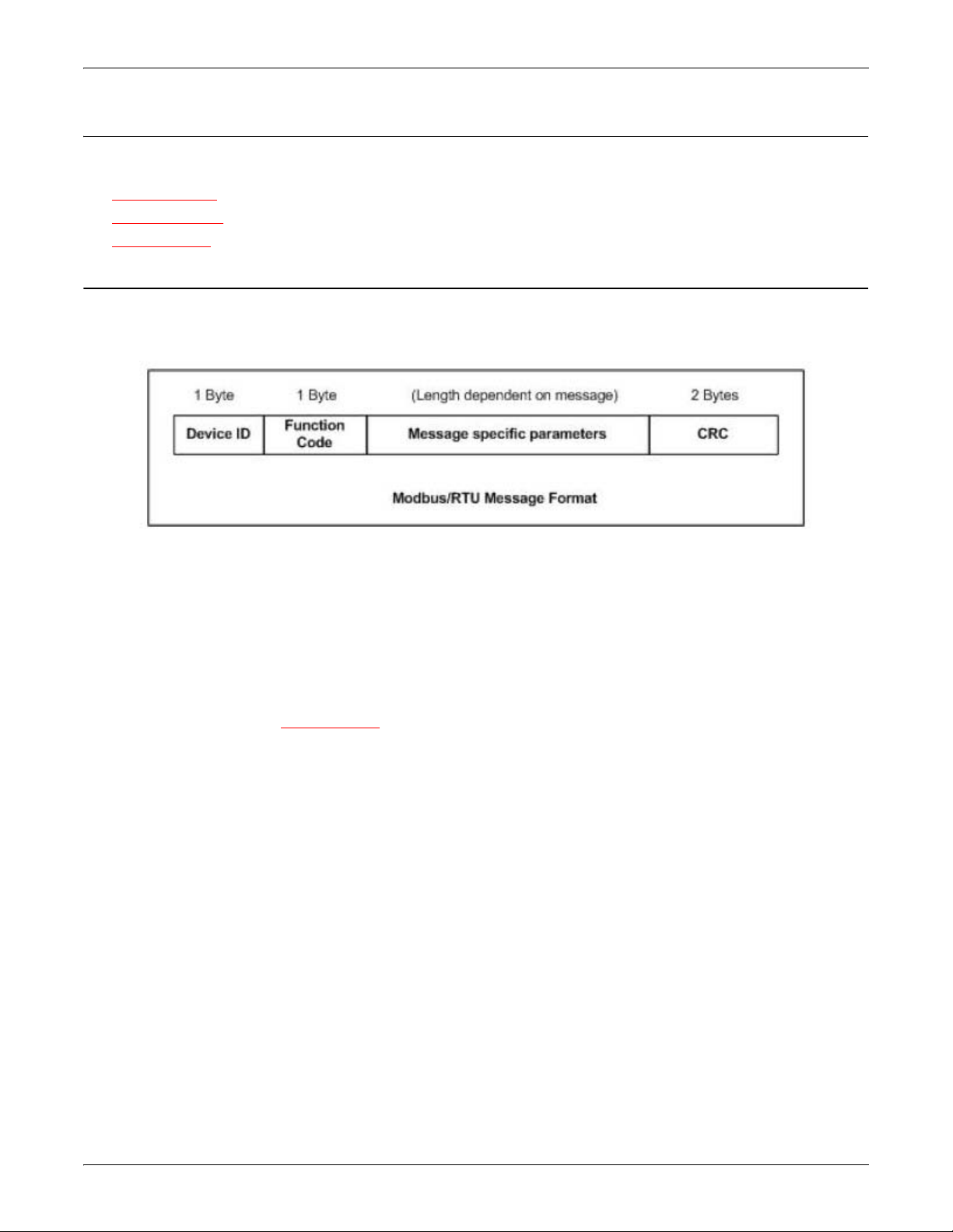
1.6.1. Modbus/RTU
Modbus/RTU is native Modbus in hexadecimal format. These are the base Modbus messages that contain
simple read and write requests. The format is as follows:
on Page 18
Where:
•The terms Master or Client are used to identify the sender of the message.
•The terms Slave or Server are used to identify the devices responding to the message.
Modbus/RTU is used primarily for:
• Serial port connectivity
RS-485 is the most common serial mode, but RS-232 and RS-422 are also widely used. Commonly used by
both Master and Slave devices.
• Ethernet TCP/IP socket connections
This is not the same as Modbus/TCP
remote devices. It is used by many applications and some OPC servers.
Note: This communication method typically is not supported by PLCs.
on Page 18, but does provide a very simple method of interfacing to
16 - Chapter 1. Introduction DeviceMaster EIP-MOD User Guide: 2000664 Rev. A
Page 17
Modbus/ASCII
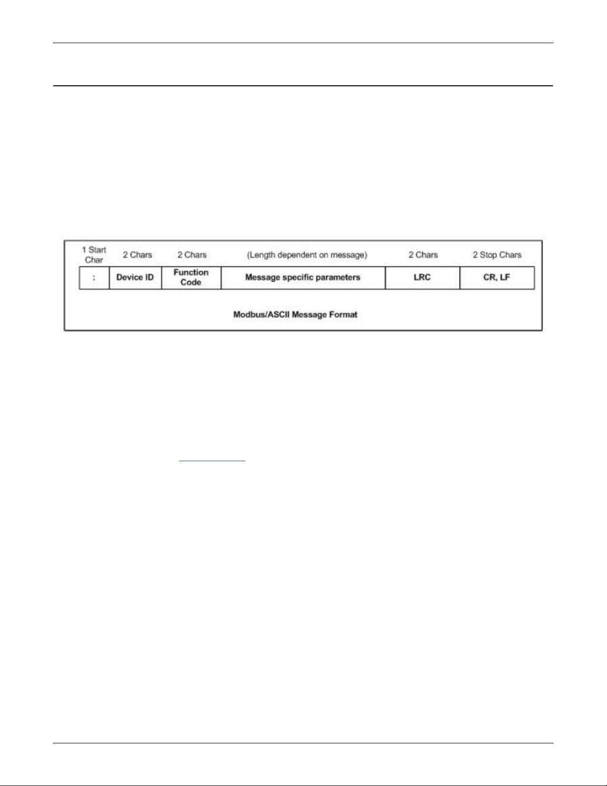
1.6.2. Modbus/ASCII
Modbus/ASCII is native Modbus in ASCII format. This protocol is used primarily by legacy devices and is no
longer supported as widely as Modbus/RTU.
Like Modbus/RTU, Modbus/ASCII contains the base Modbus messages that contain simple read and write
requests. The differences between Modbus/ASCII and Modbus/RTU are:
1. The message data is sent in ASCII format, so the message length is twice as long. It requires two ASCII
characters for each byte of data.
2. An 8-bit LRC is attached to verify the message instead of a 16-bit CRC. The LRC is also transmitted in
ASCII format.
3. There are defined starting and ending characters to determine a Modbus/ASCII messages.
The format is as follows:
Where:
•The terms Master or Client are used to identify the sender of the message.
•The terms Slave or Server are used to identify the devices responding to the message.
Modbus/ASCII is used primarily for:
• Serial port connectivity
RS-485 is the most common serial mode, but RS-232 and RS-422 are also used. Used primarily by legacy
Slave devices.
• Ethernet TCP/IP socket connections
This is not the same as
Modbus/TCP, but does provide a very simple method of interfacing to remote
devices. It is used by some applications and some OPC servers.
Note: This communication method typically is not supported by PLCs.
DeviceMaster EIP-MOD User Guide: 2000664 Rev. A Chapter 1. Introduction - 17
Page 18
Modbus/TCP
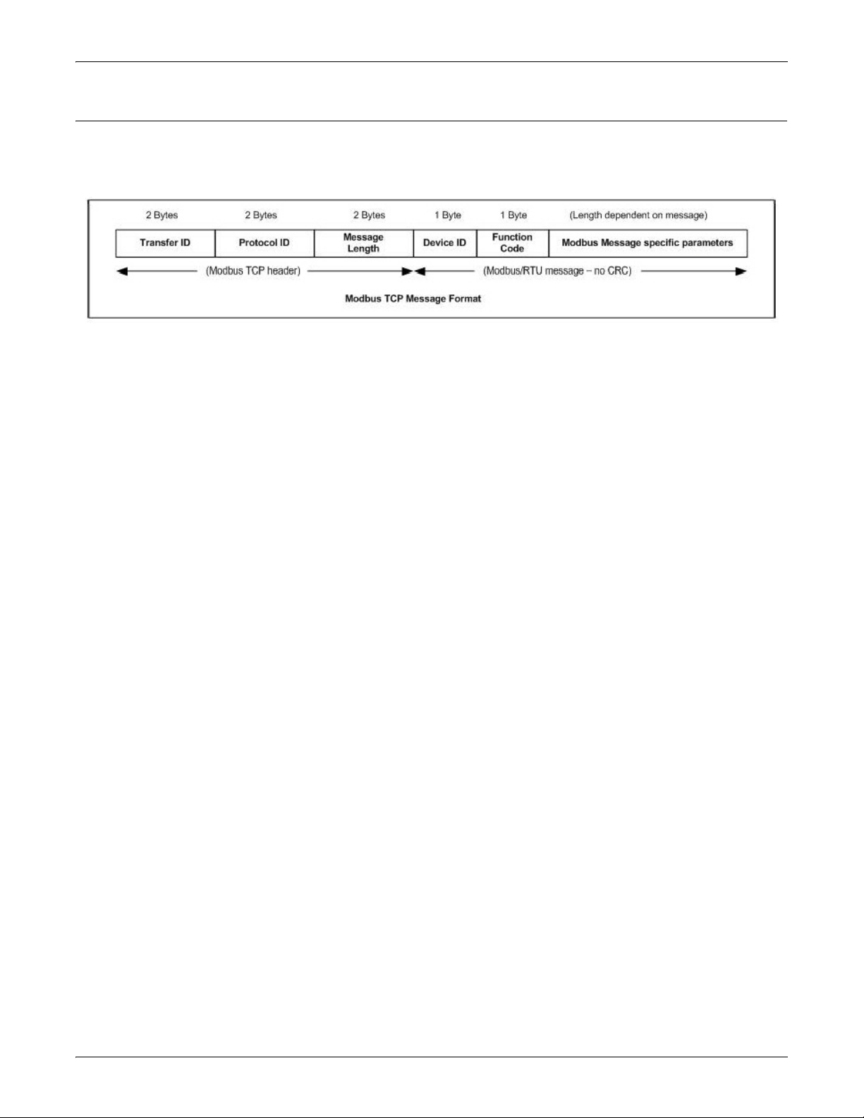
1.6.3. Modbus/TCP
Modbus/TCP is an Ethernet network based protocol that contains a Modbus/RTU message, with the exception
of the 2-byte CRC. The Modbus/TCP message contains a header with information designed to provide
message identification and routing information. The format is as follows:
Where:
•The terms Master or Client are used to identify the sender of the message.
•The terms Slave or Server are used to identify the devices responding to the message.
• Modbus/TCP messages are typically sent to and received on a defined Ethernet TCP/IP socket of 502.
• Modbus/TCP implementations provide more capability, but also require more processing than simpler
Modbus/RTU implementations.
Modbus/TCP is used for connecting advanced Ethernet based devices, such as PLCs, HMIs, SCADA Systems,
and most OPC Servers to:
• Other Ethernet devices supporting Modbus/TCP.
• Remote serial Modbus/RTU and/or Modbus/ASCII devices through gateways (such as the DeviceMaster
EIP-MOD running the EtherNet/IP-Modbus or Modbus/TCP applications).
• Remote serial or Ethernet TCP/IP ASCII devices (barcode scanners, printers, RFID readers, visions
systems, etc) through a gateway (such as the DeviceMaster EIP-MOD running the Modbus/TCP
application).
18 - Chapter 1. Introduction DeviceMaster EIP-MOD User Guide: 2000664 Rev. A
Page 19

Locating the Latest Software and Documentation
1.7. Locating the Latest Software and Documentation
You can use the links in this table to check for updated software or documentation.
Software and Documentation FTP
Use PortVision DX to manage Pepperl+Fuchs Comtrol, Inc. Ethernetattached devices to:
• Scan the network for attached devices
• View networked devices in real-time
• Access product-specific network settings configurations
• Assign IP addresses and network settings to one or multiple
devices
PortVision DX
(Windows)
EtherNet/IP-Modbus
Firmware
EtherNet/IP-Modbus
Hardware Installation and
Configuration Guide
EtherNet/IP-Modbus User
Guide
(this guide)
• Upload the latest firmware or Bootloader
• Save and load configuration files
• Access DeviceMaster EIP-MOD configuration web pages
• Access Telnet/SSH sessions
• Remotely reboot devices
• Download technical documentation
• Enable event logging to assist in monitoring and troubleshooting
• Create shortcuts to quickly access your favorite applications
• Organize devices into folders and create multiple views
• Enter notes about a folder or device
This is the application that may or may not have been loaded on the
DeviceMaster EIP-MOD depending on the model that was ordered.
You may need to use PortVision DX to load this firmware.
This contains hardware installation, configuration information, and
connector information.
This includes using PortVision DX to configure the IP address and if
necessary, how to update the firmware.
This User Guide contains detailed information about the EtherNet/IPModbus (application) firmware, which includes additional information
about the web configuration interface.
DeviceMaster EIP-MOD User Guide: 2000664 Rev. A Chapter 1. Introduction - 19
Page 20

Locating the Latest Software and Documentation
20 - Chapter 1. Introduction DeviceMaster EIP-MOD User Guide: 2000664 Rev. A
Page 21

Chapter 2. EtherNet/IP Interface Profile (ControlLogix)
This section describes the EtherNet/IP objects included in the ControlLogix EtherNet/IP interface and
supported by the DeviceMaster EIP-MOD.
2.1. Modbus Object (44 Hex, 1 Instance)
The Modbus Object provides an interface to the data and functions within a Modbus device or the Shared
memory on the DeviceMaster EtherNet/IP-Modbus gateway. It utilizes CIP object specific services to
implement Modbus functions through an explicit CIP message.
Note: The instance number is used to define the device or unit Id of the Modbus device or Shared memory.
2.1.1. Class Attributes
The following table displays the Class Attributes for Modbus Object (44 hex, 1 Instance).
There is no support for broadcast Modbus messages, which have a device Id of zero.
Attribute
ID
1 Revision UINT 1 Get
2 Max Instance UINT 255 (maximum Modbus device Id) Get
3 Num Instances UINT 255 (maximum Modbus device Id) Get
6
7
Name
Maximum
Number Class
Attribute
Maximum
Number Instance
Attribute
Data
Type
UINT 7 Get
UINT 0 Get
Data Value(s)
2.1.2. Instance Attributes
There are no Instance Attributes.
2.1.3. Common Services
This table provides the Common Services for Modbus Object (44 hex, 1 instance).
Service Code Implemented in Class Implemented in Instance Service Name
Access
Rule
0E hex Yes Yes Get_Attribute_Single
DeviceMaster EIP-MOD User Guide: 2000664 Rev. A Chapter 2. EtherNet/IP Interface Profile (ControlLogix) - 21
Page 22

| Modbus Object (44 Hex, 1 Instance) | Object Specific Services (Instance Specific) | |
2.1.4. Object Specific Services (Instance Specific)
These services are provided to implement the supported Modbus functions. All Modbus Object services, as
specified in Volume 7: Integration of Modbus Devices into the CIP Architecture, are supported as well as
several additional services.
Service Code Service Name Service Description
4B hex Read Discrete Inputs Reads one or more contiguous discrete input(s).
4C hex Read Coils Reads one or more contiguous coil(s).
4D hex Read Input Registers Reads one or more contiguous input register(s).
4E hex Read Holding Registers Reads one or more contiguous holding register(s).
4F hex Write Coils Writes one or more contiguous coil(s).
50 hex Write Holding Registers Writes one or more contiguous holding register(s).
51 hex Modbus Pass through
70 hex ** Write Single Coil Writes a single coil.
71 hex ** Write Single Register Writes a single holding register.
72 hex ** Mask Write Register
73 hex ** Read/Write Holding Registers
** = Vendor specific services provided to support additional Modbus functions.
Provides encapsulation of any public or private
Modbus function.
Perform a mask write operation on a single holding
register.
Writes one or more holding register(s) and reads one
or more holding register(s).
Note: In order to use these services, the Enable Vendor Specific Modbus Object Services option on the
EtherNet/IP Stack Configuration web page must be selected.
2.1.4.0.1. Read Discrete Inputs Service (4B Hex)
This service reads one or more discrete inputs from the Modbus Discrete Inputs table. This service results in
the DeviceMaster EIP-MOD issuing a Read Discrete Inputs function (function code 0x02) to either the Shared
Memory or the Modbus Message Routing subsystem. Refer to CIP Standard Vol1_3.22 Section 5B-3 and/or
MODBUS Application Protocol Specification V1.1b3.pdf at www.modbus.org
for more details.
2.1.4.0.2. Read Coils Service (4C Hex)
This service reads one or more coils from the Modbus Coils table. This service results in the DeviceMaster
EIP-MOD issuing a Read Coils function (function code 0x01) to either the Shared Memory or the Modbus
Message Routing subsystem. Refer to CIP Standard Vol1_3.22 Section 5B-3 and/or MODBUS Application
Protocol Specification V1.1b3.pdf at www.modbus.org
for more details.
2.1.4.0.3. Read Input Registers Service (4D Hex)
This service reads one or more input registers from the Modbus Input Register table. This service results in
the DeviceMaster EIP-MOD issuing a Read Input Registers function (function code 0x04) to either the Shared
Memory or the Modbus Message Routing subsystem. Refer to CIP Standard Vol1_3.22 Section 5B-3 and/or
MODBUS Application Protocol Specification V1.1b3.pdf at www.modbus.org
for more details.
22 - Chapter 2. EtherNet/IP Interface Profile (ControlLogix) DeviceMaster EIP-MOD User Guide: 2000664 Rev. A
Page 23

| Modbus Object (44 Hex, 1 Instance) | Object Specific Services (Instance Specific) | |
2.1.4.0.4. Read Holding Registers Service (4E Hex)
This service reads one or more holding registers from the Modbus Holding Register table. This service results
in the DeviceMaster EIP-MOD issuing a Read Holding Registers function (function code 0x03) to either the
Shared Memory or the Modbus Message Routing subsystem. Refer to CIP Standard Vol1_3.22 Section 5B-3
and/or MODBUS Application Protocol Specification V1.1b3.pdf at www.modbus.org
for more details.
2.1.4.0.5. Write Coils Service (4F Hex)
This service writes one or more coils to the Modbus Coils table. This service results in the DeviceMaster EIPMOD issuing a Write Multiple Coils function (function code 0x0F) to either the Shared Memory or the
Modbus Message Routing subsystem. Refer to CIP Standard Vol1_3.22 Section 5B-3 and/or MODBUS
Application Protocol Specification V1.1b3.pdf at www.modbus.org
for more details.
2.1.4.0.6. Write Holding Registers Service (50 Hex)
This service writes one or more holding registers to the Modbus Holding Registers table. This service results
in the DeviceMaster EIP-MOD issuing a Write Multiple Registers function (function code 0x10) to either the
Shared Memory or the Modbus Message Routing subsystem. Refer to CIP Standard Vol1_3.22 Section 5B-3
and/or MODBUS Application Protocol Specification V1.1b3.pdf at www.modbus.org
for more details.
2.1.4.0.7. Modbus Passthrough Service (51 Hex)
The Modbus Passthrough service provides a way for a client to initiate a specific Modbus function to a target
Modbus device. The Modbus request and response are encapsulated in the CIP request and response service
data fields with no modification. The DeviceMaster EIP-MOD does not attempt to perform any byte endian
conversion on the bytes in the data stream (either request or response). Refer to CIP Standard Vol1_3.22
Section 5B-3 and/or MODBUS Application Protocol Specification V1.1b3.pdf at www.modbus.org
for more
details.
2.1.4.0.8. Vendor Specific Write Single Coil Service (70 Hex)
This service writes one coil to the Modbus Coils table. This service results in the DEVICEMASTER
ETHERNET/IP- DeviceMaster EIP-MOD issuing a Write Single Coil function (function code 0x05) to either
the Shared Memory or the Modbus Message Routing subsystem. Refer to MODBUS Application Protocol
Specification V1.1b3.pdf at www.modbus.org
for more details.
Note: In order to use this service, the Enable Vendor Specific Modbus Object Services option on the EtherNet/
IP Stack Configuration web page must be selected.
2.1.4.0.9. Vendor Specific Write Single Register Service (71 Hex)
This service writes one holding register to the Modbus Holding Registers table. This service results in the
DeviceMaster EIP-MOD issuing a Write Single Registers function (function code 0x06) to either the Shared
Memory or the Modbus Message Routing subsystem. Refer to MODBUS Application Protocol Specification
V1.1b3.pdf at www.modbus.org
for more details.
Note: In order to use this service, the Enable Vendor Specific Modbus Object Services option on the EtherNet/
IP Stack Configuration web page must be selected.
2.1.4.0.10. Vendor Specific Write Mask Register (72 Hex)
This service performs a write mask operation on one holding register in the Modbus Holding Registers table.
This service results in the DeviceMaster EtherNet/IP-Modbus gateway issuing a Write Mask Register
function (function code 0x16) to either the Shared Memory or the Modbus Message Routing subsystem. Refer
to MODBUS Application Protocol Specification V1.1b3.pdf at www.modbus.org
for more details.
Note: In order to use this service, the Enable Vendor Specific Modbus Object Services option on the EtherNet/
IP Stack Configuration web page must be selected.
DeviceMaster EIP-MOD User Guide: 2000664 Rev. A Chapter 2. EtherNet/IP Interface Profile (ControlLogix) - 23
Page 24

| Informational Objects | Identity Object (01 Hex, 1 Instance) | Class Attributes |
2.1.4.0.11. Vendor Specific Read/Write Holding Registers (73 Hex)
This service performs first write and then read operations on multiple holding registers in the Modbus
Holding Registers table. This service results in the DeviceMaster EtherNet/IP-Modbus gateway issuing a
Read/Write Holding Registers function (function code 0x17) to either the Shared Memory or the Modbus
Message Routing subsystem. Refer to MODBUS Application Protocol Specification V1.1b3.pdf at
www.modbus.org
Note: In order to use this service, the Enable Vendor Specific Modbus Object Services option on the EtherNet/
IP Stack Configuration web page must be selected.
for more details.
2.2. Informational Objects
The following object definitions are included for informational purposes only. While some software packages,
such as RSLinx make use of these objects, few PLC programmers will have a need to directly access them.
2.2.1. Identity Object (01 Hex, 1 Instance)
The Identity Object provides identification of and general information about the DeviceMaster EIP-MOD.
2.2.1.1. Class Attributes
The following table provides information about the Identity Object (01 hex, 1 Instance) Class Attributes.
Attribute ID Name Data Type Data Value(s) Access Rule
1 Revision UINT 1 Get
2 Max Class UINT 1 Get
3 Max Instance UINT 1 Get
6 Maximum Number Class Attribute UINT 7 Get
7 Maximum Number Instance Attribute UINT 7 Get
2.2.1.2. Instance Attributes
The following table provides information about the Identity Object (01 hex, 1 Instance) Instance Attributes.
Attribute ID Name Data Type Data Value(s) Access Rule
1 Vendor ID UINT 909 (Pepperl+Fuchs Comtrol, Inc.) Get
2 Device Type UINT 43 (Generic product device) Get
3 Product Code UINT
Revision (product or software release)
Structure of:
4
Minor Revision USINT 1 to 999
5 Status WORD See below. Get
6 Serial Number UDINT 1-FFFFFFFF hex Get
As defined by Pepperl+Fuchs
Comtrol, Inc.
Get
GetMajor Revision USINT 1 to 127
24 - Chapter 2. EtherNet/IP Interface Profile (ControlLogix) DeviceMaster EIP-MOD User Guide: 2000664 Rev. A
Page 25

| Informational Objects | Identity Object (01 Hex, 1 Instance) | Status Word |
Attribute ID Name Data Type Data Value(s) Access Rule
Product Name
Structure of:
7
Name Length USINT Length of string
Get
Name String STRING See below
2.2.1.3. Status Word
Refer to Page 52 of Volume 3.5 of the CIP Common Specification. The following applies to the Identity Object
status word for the DeviceMaster EtherNet/IP-Modbus gateway.
Status Word Bit Setting Description
00
Ownership Flag. Does not apply to the DeviceMaster EtherNet/IPModbus gateway.
1 0 Reserved.
0
2
1
DeviceMaster EtherNet/IP-Modbus gateway is operating on the default
configuration.
The DeviceMaster EtherNet/IP-Modbus gateway has a configuration
other than the default configuration.
30Reserved
0101 (0x50) Indicates that there is a major fault (either Bit 10 or Bit 11 is set).
0100 (0x40) Indicates the stored configuration is invalid.
0011 (0x30)
0110 (0x60)
4-7
Indicates the system is operational and there are no I/O (Class 1)
connections.
Indicates the system is operational and there is at least one active I/O
(Class 1) connection.
Indicates the system is not operational. It may be in any of the following
states:
• System startup.
0000
• Configuration in process.
•Idle.
• Critical (major) fault.
0
8
1
No recoverable minor fault. No error history entry reported within the
last ten seconds.
Recoverable minor fault. The DeviceMaster EtherNet/IP-Modbus
gateway has reported an error within the last ten seconds and a major
fault has not been detected.
91
Unrecoverable minor fault. Does not apply to the DeviceMaster
EtherNet/IP-Modbus gateway.
0 No recoverable major fault.
10
1
A major recoverable fault exists. This is a fault that the DeviceMaster
EIP-MOD may be able to recover from by a system reset. If the system
does not recover automatically, a system reset message or a power cycle of
the DeviceMaster EtherNet/IP-Modbus gateway may be required.
DeviceMaster EIP-MOD User Guide: 2000664 Rev. A Chapter 2. EtherNet/IP Interface Profile (ControlLogix) - 25
Page 26

| Informational Objects | Identity Object (01 Hex, 1 Instance) | Common Services |
Status Word Bit Setting Description (Continued)
0 No major unrecoverable fault.
11
1
A major unrecoverable fault has occurred in the DeviceMaster EIP-MOD.
If the major fault is not corrected with a system reset or a power cycle,
refer to the Troubleshooting and Technical Support
on Page 155 or call
Pepperl+Fuchs Comtrol, Inc. support.
12-15 0 Reserved.
2.2.1.4. Common Services
This table displays Common Services for Identity Object (01 hex, 1 Instance).
Service Code Implemented in Class Implemented in Instance Service Name
01 hex Yes Yes Get_Attribute_All
05 hex No Yes Reset
0E hex Yes Yes Get_Attribute_Single
26 - Chapter 2. EtherNet/IP Interface Profile (ControlLogix) DeviceMaster EIP-MOD User Guide: 2000664 Rev. A
Page 27

| Informational Objects | Message Router Object (02 Hex) | Class Attributes |
2.2.2. Message Router Object (02 Hex)
The Message Router Object provides a messaging connection point through which a client may address a
service to any object or instance residing in the physical device.
2.2.2.1. Class Attributes
This table displays the Class Attributes for Message Router Object (02 hex).
Attribute ID Name Data Type Data Value Access Rule
1 Revision UINT 1 Get
2 Max Class UINT 1 Get
3 Max Instance UINT 1 Get
4 Optional Attribute List UINT 2 Get
5 Option Service List UINT 1 Get
6 Maximum Number Class Attribute UINT 7 Get
7 Maximum Number Instance Attribute UINT 2 Get
2.2.2.2. Instance Attributes
This table displays Instance Attributes for Message Router Object (02 hex).
Attribute ID Name Data Type Data Value(s) Access Rule
Object List
Structure of:
1
Number
Classes
UINT
Array of UINT List of supported
Number of supported
class codes
class codes
Get
2 Max Connections UINT 128 Get
2.2.2.3. Common Services
This table displays Common Services for Message Router Object (02 hex).
Service Code Implemented in Class Implemented in Instance Service Name
01 hex Yes No Get_Attribute_All
0E hex Yes Yes Get_Attribute_Single
0A hex No Yes Multiple_Service_Req
DeviceMaster EIP-MOD User Guide: 2000664 Rev. A Chapter 2. EtherNet/IP Interface Profile (ControlLogix) - 27
Page 28

| Informational Objects | Connection Manager Object (06 Hex) | Class Attributes Object (06 hex) |
2.2.3. Connection Manager Object (06 Hex)
The Connection Manager Object provides services for connection and connection-less communications.
2.2.3.1. Class Attributes Object (06 hex)
The following table displays the Class Attributes for the Connection Manager Object (06 hex).
Attribute ID Name Data Type Data Value(s) Access Rule
1 Revision UINT 1 Get
2 Max Class UINT 1 Get
3 Max Instance UINT 1 Get
4 Optional Attribute List UINT 8 Get
6 Maximum number Class Attribute UINT 7 Get
7 Maximum Number Instance Attributes UINT 8 Get
2.2.3.2. Instance Attributes (06 hex)
This table displays the Instance Attributes for the Connection Manager Object (06 hex).
Attribute ID Name Data Type Data Value(s) Access Rule
1 Open Requests UINT 0-0xffffffff Set/Get
2 Open Format Rejects UINT 0-0xffffffff Set/Get
3 Open Resource Rejects UINT 0-0xffffffff Set/Get
4 Open Other Rejects UINT 0-0xffffffff Set/Get
5 Close Requests UINT 0-0xffffffff Set/Get
6 Close Format Requests UINT 0-0xffffffff Set/Get
7 Close Other Requests UINT 0-0xffffffff Set/Get
8 Connection Time Outs UINT 0-0xffffffff Set/Get
2.2.3.3. Common Services Object (06 hex)
This table displays the Common Services for the Connection Manager Object (06 hex).
Service Code Implemented in Class Implemented in Instance Service Name
01 hex Yes Yes Get_Attribute_All
02 hex No Yes Set_Attribute_ALL
0E hex Yes Yes Get_Attribute_Single
10 hex No Yes Set_Attribute_Single
4E hex N/A N/A Forward_Close
52 hex N/A N/A Unconnected_Send
54 hex N/A N/A Forward_Open
5A hex N/A N/A Get_Connection_Owner
5B hex N/A N/A Large_Forward_Open
28 - Chapter 2. EtherNet/IP Interface Profile (ControlLogix) DeviceMaster EIP-MOD User Guide: 2000664 Rev. A
Page 29

| Informational Objects | Port Object (F4 Hex - 1 Instance) | Class Attributes |
2.2.4. Port Object (F4 Hex - 1 Instance)
The Port Object enumerates the CIP ports on the DeviceMaster EIP-MOD.
2.2.4.1. Class Attributes
This table displays Class Attributes for Port Object (F4 hex - 1 Instance).
Attribute
ID
Name Data Type Data Value(s)
1 Revision UINT 2 Get
2 Max Instance UINT 2 Get
3 Num Instances UINT 2 Get
6
7
Maximum Number
Class Attributes
Maximum Number
Instance Attributes
UINT 9 Get
UINT 10 Get
8 Entry Port UINT 1 Get
[0]=0
[1]=0
9 All Ports Array of UINT
[2] = 1 (Vendor Specific)
[3] = 1 (Backplane)
[4]=TCP_IP_PORT_TYPE (4)
[5]=TCP_IP_PORT_NUMBER(2)
2.2.4.2. Instance Attributes (F4 Hex, Instance 1)
This table illustrates the Instance Attributes for the Port Object (F4 hex – Instance 1).
Access
Rule
Get
Attribute
ID
Name Data Type Data Value(s)
Access
Rule
1 Port Type UINT 1 Get
2 Port Number UINT 1 Get
Port Object
Structure of:
3
16-bit word count in path UINT 2
Get
Path Array of UINT [0]=6420 hex
[1]=0124
Port Name
4
Structure of:
Get
String Length USINT 10
Port Name Array of USINT “Backplane”
7 Node Address USINT[2] 10 hex, 0 hex Get
DeviceMaster EIP-MOD User Guide: 2000664 Rev. A Chapter 2. EtherNet/IP Interface Profile (ControlLogix) - 29
Page 30

| Informational Objects | Port Object (F4 Hex - 1 Instance) | Instance Attributes (F4 Hex, Instance 2) |
Attribute
ID
Name Data Type Data Value(s)
17 hex:
• Bit 0: Routing of incoming
Unconnected Messaging supported
• Bit 1: Routing of outgoing
10 Port Routing Capabilities UDINT
Unconnected Messaging supported
• Bit 2: Routing of incoming Transport
Class 0/1 Connections supported
• Bit 4: Routing of incoming Transport
Class 2/3 Connections supported
2.2.4.3. Instance Attributes (F4 Hex, Instance 2)
This table illustrates the Instance Attributes for the Port Object (F4 hex – Instance 2).
Attribute
ID
Name Data Type Data Value(s)
1 Port Type UINT 4 (TCP/IP) Get
2 Port Number UINT 2 (TCP/IP) Get
Port Object
Structure of:
3
16-bit word count in path UINT 2
Path Array of UINT [0]=F520 hex
[1]=0124 hex
Port Name
Structure of:
4
String Length USINT 17
Port Name Array of USINT “Ethernet/IP Port”
7 Node Address USINT[2] 10 hex, 0 hex Get
17 hex:
Bit 0: Routing of incoming
Unconnected Messaging supported
Bit 1: Routing of outgoing
10 Port Routing Capabilities UDINT
Unconnected Messaging supported
Bit 2: Routing of incoming Transport
Class 0/1 Connections supported
Bit 4: Routing of incoming Transport
Class 2/3 Connections supported
Access
Rule
Get
Access
Rule
Get
Get
Get
30 - Chapter 2. EtherNet/IP Interface Profile (ControlLogix) DeviceMaster EIP-MOD User Guide: 2000664 Rev. A
Page 31

| Informational Objects | TCP Object (F5 Hex - 1 Instance) | Common Services |
2.2.4.4. Common Services
This table displays Common Services for Port Object (F4 hex, Instance 2).
Service Code Implemented in Class Implemented in Instance Service Name
01 hex Yes Yes Get_Attribute_All
0E hex Yes Yes Get Attribute Single
2.2.5. TCP Object (F5 Hex - 1 Instance)
The TCP/IP Interface Object provides the mechanism to retrieve the TCP/IP attributes for the DeviceMaster
EIP-MOD.
2.2.5.1. Class Attributes
This table displays the Class Attributes for TCP Object (F5 hex - 1 instance).
Attribute ID Name Data Type Data Value Access Rule
1Revision UINT 4Get
2 Max Instance UINT 1 Get
3 Num Instances UINT 1 Get
4 Optional Attribute List UINT 4 Get
6 Maximum Number Class Attribute UINT 7 Get
7 Maximum Number Instance Attribute UINT 13 Get
2.2.5.2. Instance Attributes
This table displays Instance Attributes for TCP Object (F5 hex - 1 instance).
Attribute
ID
Name Data Type Data Value(s)
Access
0 = The Interface Configuration
attribute has not been configured.
1 Status DWORD
1 = The Interface Configuration
attribute contains configuration
Get
obtained from DHCP or nonvolatile
storage.
2 Configuration Capability DWORD 14 hex (DHCP and SETTABLE) Get
0=Use stored IP address (static IP
3 Configuration Control DWORD
address)
Get
2=DHCP
Rule
DeviceMaster EIP-MOD User Guide: 2000664 Rev. A Chapter 2. EtherNet/IP Interface Profile (ControlLogix) - 31
Page 32

| Informational Objects | TCP Object (F5 Hex - 1 Instance) | Instance Attributes |
Attribute
ID
4
5
6
8
9
13
Name Data Type Data Value(s)
Physical Link Object
Structure of:
Path Size UINT 2
Path Array of USINT [0]=20 hex
[1]=F6 hex
[2]=24 hex
[3]=01 hex
Interface Configuration
Structure of:
IP Address UDINT <IP address>
Network Mask UDINT <Network mask>
Gateway Address UDINT <Gateway Addr>
Name Server UDINT <Name server>
Name Server 2 UDINT <Name server 2>
Domain Name UINT <Length of name>
Length Domain Name STRING <Domain name>
Host Name
Structure of:
Host Name Length UINT 0 to 15
Host Name STRING <Default = IP address>
TTL (Time-to-Live) value
for IP multicast packets
USINT
1 to 255
<Default = 1>
Struct of:
USINT –Allocation Allocation Control
0=Default Algorithm
1 = Configuration
Num Multicast Addresses:
1-32
IP Multicast Address
Configuration
Control
USINT – Reserved
UINT – Num Mcast
Start Multicast Address:
UDINT – Start
Multicast Address
239.192.1.0 to
239.255.255.255
Encapsulation Inactivity
Timeout USINT
Number of seconds of inactivity
before TCP connection or DTLS
session is closed
Access
Rule
Get
Set
Set
Set
Set
Set
32 - Chapter 2. EtherNet/IP Interface Profile (ControlLogix) DeviceMaster EIP-MOD User Guide: 2000664 Rev. A
Page 33

| Informational Objects | Ethernet Link Object (F6 Hex) | Common Services |
2.2.5.3. Common Services
This table shows the Common Services for the TCP Object (F5 hex - I Instance).
Service Code Implemented in Class Implemented in Instance Service Name
01 hex Yes Yes Get_Attribute_All
02 hex No Yes Set_Attribute_All
0E hex Yes Yes Get_Attribute_Single
10 hex No Yes Set_Attribute_Single
2.2.6. Ethernet Link Object (F6 Hex)
The Ethernet Link object maintains link-specific counters and status information for the Ethernet
communications on the DeviceMaster EIP-MOD.
2.2.6.1. Class Attributes
This table displays the Class Attributes for the Ethernet Link Object (F6 hex).
Attribute ID Name Data Type Data Value(s) Access Rule
1 Revision UINT 4 Get
2 Max Instance UINT
3 Num Instances UINT
4
Optional Attribute
List
UINT 4 Get
1 = One Ethernet Port Models
3 = Two Ethernet Port Models
1 = One Ethernet Port Models
3 = Two Ethernet Port Models
Get
Get
Maximum
6
Number Class
UINT 7 Get
Attributes
Maximum
7
Number Instance
UINT 11 Get
Attributes
DeviceMaster EIP-MOD User Guide: 2000664 Rev. A Chapter 2. EtherNet/IP Interface Profile (ControlLogix) - 33
Page 34

| Informational Objects | Ethernet Link Object (F6 Hex) | Instance Attributes |
2.2.6.2. Instance Attributes
This table displays the Instance Attributes for the Ethernet Link Object (F6 hex).
Attribute
ID
1
Interface speed (Current
operational speed)
Name Data Type Data Value(s) Access Rule
UDINT
10=10 Mbit
100=100 Mbit
Get
Bit 0 =link status
(0=inactive)
(1=active)
Bit 1=Half/Full Duplex
(0=half duplex)
2
Interface Flags (Current
operational status)
DWORD
(2=full duplex)
Get
Bits 2-4:
00 = negotiation in progress
01 = negotiation failed
02 = negotiation failed speed OK
03 = negotiation success
3 Physical Address Array of 6 USINT MAC Address Get
7 Interface Type USINT 2 = Twisted Pair Get
8 Interface State USINT
1 = Interface is enabled and
operational
Get
9 Admin State USINT 1 = Interface enabled Get
USINT16 Length = 1 to 64 ASCII characters
10 Interface Label
Array of USINT <Default = IP address in
Get
“xxx.xxx.xxx.xxx” format>
Capability bits - Interface
capabilities, other than speed/
duplex
UDINT
Value = 6
Bit 1: Auto-negotiate
Bit 2: Auto-MDIX
11 Interface Capability
Struct of:
Get6
USINT Speed/Duplex Array Count = 1
Array of:
UINT Interface Speed - 10 or 100
Interface Duplex Mode
USINT
0=half duplex
1=full duplex
34 - Chapter 2. EtherNet/IP Interface Profile (ControlLogix) DeviceMaster EIP-MOD User Guide: 2000664 Rev. A
Page 35

| Informational Objects | Assembly Object (For Class 1 Interface) | Common Services |
2.2.6.3. Common Services
This table displays the Common Services for Ethernet Link Object (F6 hex).
Service Code Implemented in Class Implemented in Instance Service Name
01 hex Yes Yes Get_Attribute_All
0E hex Yes Yes Get_Attribute_Single
2.2.7. Assembly Object (For Class 1 Interface)
The EtherNet/IP specification requires that all Class 1 interfaces be provided through the Assembly Object
interface. The Assembly Object interface is used to directly tie Vendor Specific objects to a standard interface,
which the EtherNet/IP controller, or PLC, uses to communicate to the device.
For the DeviceMaster EtherNet/IP-Modbus gateway, the Assembly Object corresponds to the Serial and
Socket Data Transfer objects. Each instance of the Assembly Object corresponds to one or more of the Serial
and/or Socket Data Transfer Object attributes.
The Assembly object defines the interface by which a Class 1 PLC or controller can:
• Request the receive data packets from the DeviceMaster EtherNet/IP-Modbus gateway.
• Write the transmit data to the DeviceMaster EtherNet/IP-Modbus gateway.
2.2.7.1. Class Attributes
This table shows the Class Attributes for the Assembly Object for a Class 1 Interface.
Attribute ID Name Data Type
Data
Value(s)
Access Rule
1Revision UINT 2Get
2 Max Instance UINT 132 Get
3 Num Instances UINT 32 Get
4 Optional Attribute List UINT 4 Get
6 Maximum Number Class Attribute UINT 7 Get
7 Maximum Number Instance Attribute UINT 4 Get
2.2.7.2. Instance Attributes
This table shows the Instance Attributes for the Assembly Object for a Class 1 Interface.
Attribute ID Name Data Type Data Value(s) Access Rule
3 Data Array of BYTE 0-255 Get/Set
4 Data Length UINT
Maximum number of bytes
in Attribute 3
Get
DeviceMaster EIP-MOD User Guide: 2000664 Rev. A Chapter 2. EtherNet/IP Interface Profile (ControlLogix) - 35
Page 36

| Informational Objects | Assembly Object (For Class 1 Interface) | Common Services |
2.2.7.2.1. Instance Attribute Definitions: Attribute 3-Request/Write Data
Dependent on the instance number, this is either the PDI data block and/or the PDO data block.
2.2.7.2.2. Instance Attribute Definitions: Attribute 4-Data Length
This is the maximum data length for each Assembly instance.
2.2.7.3. Common Services
This table shows the Common Services for the Assembly Object for a Class 1 Interface.
Service Code Implemented in Class Implemented in Instance Service Name
01 hex Yes No Get_Attributes_All
0E hex Yes Yes Get_Attribute_Single
10 hex No Yes Set_Attribute_Single
02 hex No No Set_Attribute_All
2.2.7.4. Instance Definitions
Each Assembly instance is tied directly to a Shared Memory block of Holding Registers or Coils. Each input
instance is enabled only if the corresponding block’s Read Class1 Enable has been selected in the Shared
Memory configuration. Each output instance is enabled only if the corresponding block’s Write Master(s)
option has been set to EIP Class1.
2.2.7.4.1. Instance Definitions (Default)
This table shows the Assembly Object instance definitions for the default Shared Memory configuration.
Default Configuration Shared Memory Configuration
Holding Register Block 1 Read Class1 Enable selected
Coils Block 1 Read Class1 Enable selected
Holding Register Block 2 Write Master(s) set to EIP Class1
Coils Block 2 Write Master(s) set to EIP Class1
For all other Shared Memory blocks:
• Read Class1 Enable not selected
• Write Master(s) not set to EIP Class1
Assembly Input Instances
Assembly
Instance
Number
Description Data Type Data Values
Access
Rule
101
109
36 - Chapter 2. EtherNet/IP Interface Profile (ControlLogix) DeviceMaster EIP-MOD User Guide: 2000664 Rev. A
Read data from Shared Memory
Holding Registers Block 1
Read data from Shared Memory
Coils Block 1
WORD Array
Length = 200
WORD Array
Length = 20 Words (320 coils)
0-FFFF (hex) Get
0-FFFF (hex) Get
Page 37

| Informational Objects | Assembly Object (For Class 1 Interface) | Instance Definitions |
Assembly Output Instances
Assembly
Instance
Description Data Type Data Values
Number
118
126
Write data to Shared Memory
Holding Registers Block 2
Write data to Shared Memory
Coils Block 2
WORD Array
Length = 200
WORD Array
Length = 20 Words (320 coils)
2.2.7.4.2. All Available Instance Definitions
This table displays all available Instance Definitions.
Assembly Input Instances
Assembly
Instance
Description Data Type Data Values
Number
101
102
103
104
105
106
107
108
109
110
111
Read data from Shared
Memory Holding Registers
Block 1
Read data from Shared
Memory Holding Registers
Block 2
Read data from Shared
Memory Holding Registers
Block 3
Read data from Shared
Memory Holding Registers
Block 4
Read data from Shared
Memory Holding Registers
Block 5
Read data from Shared
Memory Holding Registers
Block 6
Read data from Shared
Memory Holding Registers
Block 7
Read data from Shared
Memory Holding Registers
Block 8
Read data from Shared
Memory Coils Block 1
Read data from Shared
Memory Coils Block 2
Read data from Shared
Memory Coils Block 3
WORD Array
Length = 200
WORD Array
Length = 200
WORD Array
Length = 200
WORD Array
Length = 200
WORD Array
Length = 200
WORD Array
Length = 200
WORD Array
Length = 200
WORD Array
Length = 200
WORD Array
Length = 20 Words (320 coils)
WORD Array
Length = 20 Words (320 coils)
WORD Array
Length = 20 Words (320 coils)
Access
0-FFFF (hex) Set
0-FFFF (hex) Set
Access
Rule
0-FFFF (hex)
Get
0-FFFF (hex) Get
0-FFFF (hex) Get
0-FFFF (hex) Get
0-FFFF (hex) Get
0-FFFF (hex) Get
0-FFFF (hex) Get
0-FFFF (hex) Get
0-FFFF (hex) Get
0-FFFF (hex) Get
0-FFFF (hex) Get
Rule
DeviceMaster EIP-MOD User Guide: 2000664 Rev. A Chapter 2. EtherNet/IP Interface Profile (ControlLogix) - 37
Page 38

| Informational Objects | Assembly Object (For Class 1 Interface) | Instance Definitions |
Assembly Input Instances (Continued)
Assembly
Instance
Number
112
113
114
115
116
Assembly
Instance
Number
117
118
119
120
121
122
123
124
125
126
127
Description Data Type Data Values
Read data from Shared
Memory Coils Block 4
Read data from Shared
Memory Coils Block 5
Read data from Shared
Memory Coils Block 6
Read data from Shared
Memory Coils Block 7
Read data from Shared
Memory Coils Block 8
Assembly Output Instances
Description Data Type Data Values
Write data to Shared Memory
Holding Registers Block 1
Write data to Shared Memory
Holding Registers Block 2
Write data to Shared Memory
Holding Registers Block 3
Write data to Shared Memory
Holding Registers Block 4
Write data to Shared Memory
Holding Registers Block 5
Write data to Shared Memory
Holding Registers Block 6
Write data to Shared Memory
Holding Registers Block 7
Write data to Shared Memory
Holding Registers Block 8
Write data to Shared Memory
Coil Block 1
Write data to Shared Memory
Coil Block 2
Write data to Shared Memory
Coil Block 3
WORD Array
Length = 20 Words (320 coils)
WORD Array
Length = 20 Words (320 coils)
WORD Array
Length = 20 Words (320 coils)
WORD Array
Length = 20 Words (320 coils)
WORD Array
Length = 20 Words (320 coils)
WORD Array
Length = 200
WORD Array
Length = 200
WORD Array
Length = 200
WORD Array
Length = 200
WORD Array
Length = 200
WORD Array
Length = 200
WORD Array
Length = 200
WORD Array
Length = 200
WORD Array
Length = 20 Words (320 coils)
WORD Array
Length = 20 Words (320 coils)
WORD Array
Length = 20 Words (320 coils)
Access
Rule
0-FFFF (hex) Get
0-FFFF (hex) Get
0-FFFF (hex) Get
0-FFFF (hex) Get
0-FFFF (hex) Get
Access
Rule
0-FFFF (hex) Set
0-FFFF (hex) Set
0-FFFF (hex) Set
0-FFFF (hex) Set
0-FFFF (hex) Set
0-FFFF (hex) Set
0-FFFF (hex) Set
0-FFFF (hex) Set
0-FFFF (hex) Set
0-FFFF (hex) Set
0-FFFF (hex) Set
38 - Chapter 2. EtherNet/IP Interface Profile (ControlLogix) DeviceMaster EIP-MOD User Guide: 2000664 Rev. A
Page 39

| Informational Objects | Assembly Object (For Class 1 Interface) | Instance Definitions |
Assembly Output Instances (Continued)
Assembly
Instance
Number
128
129
130
131
132
Description Data Type Data Values
Write data to Shared Memory
Coil Block 4
Write data to Shared Memory
Coil Block 5
Write data to Shared Memory
Coil Block 6
Write data to Shared Memory
Coil Block 7
Write data to Shared Memory
Coil Block 8
WORD Array
Length = 20 Words (320 coils)
WORD Array
Length = 20 Words (320 coils)
WORD Array
Length = 20 Words (320 coils)
WORD Array
Length = 20 Words (320 coils)
WORD Array
Length = 20 Words (320 coils)
Access
Rule
0-FFFF (hex) Set
0-FFFF (hex) Set
0-FFFF (hex) Set
0-FFFF (hex) Set
0-FFFF (hex) Set
DeviceMaster EIP-MOD User Guide: 2000664 Rev. A Chapter 2. EtherNet/IP Interface Profile (ControlLogix) - 39
Page 40

| Informational Objects | Assembly Object (For Class 1 Interface) | Instance Definitions |
40 - Chapter 2. EtherNet/IP Interface Profile (ControlLogix) DeviceMaster EIP-MOD User Guide: 2000664 Rev. A
Page 41

Chapter 3. Configuration Overview
This chapter provides an overview of these topics:
• 3.1.
• 3.2.
3.1. Home Page
If you have not configured the network information into the DeviceMaster EIP-MOD during initial setup, you
must configure the network information before configuring serial/socket port characteristics.
The latest EtherNet/IP-Modbus firmware must be installed before you can configure network or serial/socket
port characteristics. For firmware installation and setup information, see the DeviceMaster EIP-MOD
Hardware Installation and Configuration Guide or the PortVision DX help system.
From PortVision DX, highlight the DeviceMaster EIP-MOD that you want to configure and click Webpage or
enter the IP address of the DeviceMaster EIP-MOD in the Address box of your web browser. The Home page
displays.
Home Page on Page 41
Serial Port - Configuration Overview on Page 43
DeviceMaster EIP-MOD User Guide: 2000664 Rev. A Chapter 3. Configuration Overview- 41
Page 42

Home Page
EtherNet/IP-Modbus Home Page
Firmware EtherNet/IP-Modbus firmware version currently running on the DeviceMaster.
Device Name
You can enter a Device Name in the Network | Configuration page, which will
display in this field.
Serial Number The DeviceMaster EIP-MOD serial number.
MAC Address
System Uptime
This is the MAC address of this DeviceMaster EIP-MOD, which is located on the
compliance label on the DeviceMaster EIP-MOD.
Displays how long this DeviceMaster EIP-MOD has been on-line since powered
on or rebooted.
IP Config Type of IP configuration currently in use (static or DHCP).
IP Address, IP
Netmask, IP
IP address, netmask, and gateway configured in the DeviceMaster EIP-MOD.
Gateway
Use the appropriate chapter as a reference for the configuration options.
• Chapter 4. Serial Menus
• Chapter 5. Modbus Menus
on Page 47
on Page 53
You can review the configuration pages and basic procedures in the following subsections.
• 3.2.
• 3.3.
Serial Port - Configuration Overview on Page 43
Modbus Over TCP Overview - Configuration Overview on Page 45
42 - Chapter 3. Configuration Overview DeviceMaster EIP-MOD User Guide: 2000664 Rev. A
Page 43

Serial Port - Configuration Overview
3.2. Serial Port - Configuration Overview
Use the following steps to access the serial port configuration pages.
1. Open the DeviceMaster EIP-MOD web page using the IP address in your browser or PortVision DX.
2. Click the Serial menu, which opens the Serial Port Overview page.
DeviceMaster EIP-MOD User Guide: 2000664 Rev. A Chapter 3. Configuration Overview- 43
Page 44

Serial Port - Configuration Overview
3. Click the port number that you want to configure and the Serial Settings | Port Configuration page
appears.
4. Change the serial port configuration properties (Page 48) as required for your site.
5. Click the Save button.
44 - Chapter 3. Configuration Overview DeviceMaster EIP-MOD User Guide: 2000664 Rev. A
Page 45

Modbus Over TCP Overview - Configuration Overview
3.3. Modbus Over TCP Overview - Configuration Overview
Use the following overview to configure the Modbus device.
1. Click the Modbus menu, which opens the Modbus over TCP Overview (not Modbus/TCP) page.
2. Click the appropriate Socket number to access the Modbus over TCP (not Modbus/TCP) Socket
Configuration page for that port.
DeviceMaster EIP-MOD User Guide: 2000664 Rev. A Chapter 3. Configuration Overview- 45
Page 46

Modbus Over TCP Overview - Configuration Overview
3. Change the socket configuration properties (Page 53) as required for you site.
4. Click the Save button after completing the changes.
5. Repeat the previous steps for each serial port and Modbus device.
46 - Chapter 3. Configuration Overview DeviceMaster EIP-MOD User Guide: 2000664 Rev. A
Page 47

Chapter 4. Serial Menus
This section discusses the 4.1. Serial Port Overview Page and 4.2. Serial Port Configuration Page on Page 48,
which are located under the Serial menu.
4.1. Serial Port Overview Page
The Serial Port Overview page displays information about the configured serial settings for each port.
Valid Rcvd Msg Device ID Range (1-255) – (1-255): Displays the valid received message device ID range.
Messages with other valid device IDs will not be transmitted out this port. (Informational only.)
Valid On Port Device ID Range (1-255) – (1-255): Displays the valid device ID range for slave devices connected
to the serial port. Slave devices with other device IDs will not be accessible on this port. (Informational only.)
For additional diagnostic information, see Chapter 8. Diagnostic Menus
DeviceMaster EIP-MOD User Guide: 2000664 Rev. A Chapter 4. Serial Menus- 47
on Page 91.
Page 48

Serial Port Configuration Page
4.2. Serial Port Configuration Page
To access the Serial Port Configuration page, click Serial | Port x.
48 - Chapter 4. Serial Menus DeviceMaster EIP-MOD User Guide: 2000664 Rev. A
Page 49

Serial Port Configuration Page
The following tables provide information about serial configuration settings.
Serial Configuration Page
Serial Configuration
Port Name (Default =
blank)
Port Mode (Default =
RS-232)
Baud Rate (Default =
38400)
Parity
(Default = None)
Data Bits (Default =
8)
User-definable string used to describe the serial interface. Valid characters include
a-z, A-Z, 0-9, underscores, spaces and dashes. All other characters are discarded.
The Port Name supports up to an 80 character ASCII string.
All panel or rack mount models:
• RS-232 (default)
•RS-485
•RS-422
All DIN rail models:
• RS-232 (default)
•RS-422
• RS-485_2-wire
• RS-485_4-wire_Master
• RS-485_4-wire_Slave
300, 600, 1200, 2400, 4800, 9600, 19200, 38400, 57600, 115200, and 230400
None
Even
Odd
5, 6, 7, 8
Stop Bits (Default =
1)
Flow Control (Default
= None)
Terminating Resistor
(Only displays on
applicable models)
DTR Mode (Default =
Off)
1 or 2
RTS/CTS
XON/XOFF
Half Duplex
To ensure the best signal integrity on a long distance high-speed RS-422 or RS-485
network, sometimes it is required to place a 120Ω termination resistor between
each of the transmit differential pair or receive differential pair. Signal reflection
is reduced and a reliable communication is ensured by placing the 120Ω
termination resistor. Using the software, you can place 120Ω termination resistors
between the signals shown below:
• RS-422 Mode
- Between TxD+ and TxD- (Pin 5 and 7)
- Between RxD+ and RxD- (Pin 4 and 2)
• RS-485 - Between TxD/RxD+ and TxD/RxD- (Pin 5 and 7)
0=Off
1=On
DeviceMaster EIP-MOD User Guide: 2000664 Rev. A Chapter 4. Serial Menus- 49
Page 50

Serial Port Configuration Page
Serial Configuration Page (Continued)
Rx Timeout Between
Packets (ms) (Default
= 200)
Discard Rx Packets
With Errors (Default
= On)
Modbus Settings
Serial Port Protocol
(Default = Modbus/
RTU-to-Slaves)
Receive time-out (0-65535) between packets in msec. This is the maximum spacing
between received bytes allowed before the received Modbus serial message is
expected to be complete.
On or Off: If selected, the DeviceMaster EIP-MOD drops all packets received with
parity, framing, or overrun errors.
Note: Modbus/RTU messages with invalid CRCs and Modbus/ASCII messages
without correct start and end of transmission characters are always
discarded independent of this setting.
The Modbus protocol, setting for this serial port:
• Modbus/RTU-to-Slaves – Configures the serial port to communicate to Modbus/
RTU slaves.
• Modbus/ASCII-to-Slaves – Configures the serial port to communicate to
Modbus/ASCII slaves.
• Modbus/RTU-to-Master – Configures the serial port to communicate to a
Modbus/RTU master.
• Modbus/ASCII-to-Master – Configures the serial port to communicate to a
Modbus/ASCII master.
• Modbus/RTU-to-Master/Slaves – Configures the serial port to communicate to a
serial bus with a Modbus/RTU master and Modbus/RTU slave(s).
• Modbus/ASCII-to-Master/Slaves – Configures the serial port to communicate to
a serial bus with a Modbus/ASCII master and Modbus/ASCII slaves.
Response Timeout
(Default = 750msec)
Lost Device Search
Enable
Not supported: 1-port
(Default = Off)
Inactivity Wait Time
Before Tx (ms)
(Default = 0 ms)
Send Write Messages
First (Default = Off)
Disable Writes (Read
Only) (Default = Off)
Device ID Offset
Mode (Default = Off)
Modbus To-Slaves Settings
The maximum allowable time (0 to 65535 msec.) for a slave device to respond to a
message before the message is considered timed out.
If selected, lost devices that were on this port are searched for on other Modbus/
RTU and Modbus/ASCII slave ports that also have this option set.
The minimum time (0 to 65535 msec.) that the DeviceMaster EIP-MOD waits after
receiving a response or transmitting a Modbus request before transmitting the
next request.
If selected, it transmits any write messages before transmitting any read
messages that may have already been queued for transmission.
If selected, it disables transmission of all standard Modbus write messages.
• Off disables Device ID Offset functionality.
• Add-to-Msg-ID adds the Device Offset to the message device ID.
• Subtract-from-Msg-ID
subtracts the Device ID Offset from the message device
ID.
50 - Chapter 4. Serial Menus DeviceMaster EIP-MOD User Guide: 2000664 Rev. A
Page 51

Serial Port Configuration Page
• 0 = disables Device ID Offset functionality.
Device ID Offset
• 1-254 = dependent on the Device ID Offset Mode, is added to or subtracted from
Modbus To-Master Settings
Serial Configuration Page (Continued)
the message device ID before the Modbus message is transmitted out the
serial port.
Discard Modbus
Errors (Default = Off)
If selected, all broadcast messages from the serial master will be forwarded to the
Modbus network through the DeviceMaster EIP-MOD.
Modbus Master/Slave Settings
Forward Broadcasts
from Master (Default
= Off)
If selected, all broadcast messages from the serial master will be forwarded to the
Modbus network through the DeviceMaster EIP-MOD.
This range (1-255) defines the expected slave device ID range on the serial bus.
Modbus request messages received on this port within this device ID range will
Private Slave Device
ID Range (Default:
Min = 1, Max = 1)
not be forwarded to the Modbus network.
Note: The DeviceMaster EIP-MOD has a built-in auto-detect algorithm for
detecting private slave device(s) with ID(s) not defined within the private
device ID range.
Note: The minimum value must be less than or equal to the maximum value.
DeviceMaster EIP-MOD User Guide: 2000664 Rev. A Chapter 4. Serial Menus- 51
Page 52

Serial Port Configuration Page
52 - Chapter 4. Serial Menus DeviceMaster EIP-MOD User Guide: 2000664 Rev. A
Page 53

Chapter 5. Modbus Menus
This chapter discusses the following Modbus web pages:
• 5.1.
• 5.2. Modbus over TCP (not Modbus/TCP) Socket Configuration Page on Page 54
• 5.3.
• 5.4.
• 5.5.
5.1. Modbus over TCP (not Modbus/TCP) Overview
The Modbus over TCP (not Modbus/TCP) Overview page provides an overview of the current settings for the
ports.
Modbus over TCP (not Modbus/TCP) Overview
Modbus/TCP Configuration Page on Page 56
Remote Modbus/TCP Device Configuration on Page 57
Modbus Alias Configuration on Page 59
DeviceMaster EIP-MOD User Guide: 2000664 Rev. A Chapter 5. Modbus Menus- 53
Page 54

Modbus over TCP (not Modbus/TCP) Socket Configuration Page
5.2. Modbus over TCP (not Modbus/TCP) Socket Configuration Page
Access the Modbus over TCP (not Modbus/TCP Socket Configuration page by clicking Modbus | TCP/IP
Configuration | Socket x. The following table provides information about each configuration setting.
Modbus over TCP (not Modbus/TCP) Socket Configuration Page
TCP Configuration
• Modbus/RTU-to-Master – Configures the TCP/IP connection(s) to
Connect To Mode
communicate to Modbus/RTU master(s).
• Modbus/ASCII-to-Master – Configures the TCP/IP connection(s) to
communicate to Modbus/ASCII master(s).
Enable (Default = Off) If selected, this TCP/IP socket interface will be enabled.
Listen (Default = Off)
54 - Chapter 5. Modbus Menus DeviceMaster EIP-MOD User Guide: 2000664 Rev. A
If selected, the TCP/IP socket interface will listen for a connection at the
specified Listen Port.
Page 55

Modbus over TCP (not Modbus/TCP) Socket Configuration Page
Modbus over TCP (not Modbus/TCP) Socket Configuration Page (Continued)
The Listen Port values are 1-65535.
Listen Port
(Defaults:
Port 1=8000
Port 2=8001
Port 3=8002
Port 4=8003)
If Enable and Listen are both selected, allows acceptance of:
• Up to six connections from external applications if there is no active
Connect-to connection.
• Up to five connections if there is an active Connect-to connection.
The following TCP/IP ports are not allowed: 0, 22, 23, 80, 443, 502, 4606, and
4607.
If Enable is selected, this setting determines how to connect to an application.
Connect to Mode
(Default = Never)
•If Never: Do not attempt to make a connection.
•If Connect-Always: Always attempt to maintain a connection to the
application at Connect IP Address and Connect Port.
Connect Port
(Default = 0)
Connect IP Address
(Default = 0)
Disconnect Mode
(Default = Never)
Idle Timer
(Default = 0)
Rx Timeout Between
Packets
(Default = 100)
Discard Modbus Error
Responses
Socket port to connect to (1 to 65535). Used in conjunction with Connect to
Mode and Connect IP Address.
IP Address of application to create a connection. Used in conjunction with
Connect to Mode and Connect Port.
Note: The IP Address of this DeviceMaster EIP-MOD will not be accepted as
valid configuration data.
Mode on which to disconnect from the application.
• Never – Will not disconnect when connection(s) are idle.
• Idle – Utilizes the Idle Timer to determine when to close the connection.
If the Disconnect Mode is set to Idle, the idle or inactivity time (1 to 65535 ms)
when the connection(s) will be closed.
Receive timeout (0-65565) between packets in msec. This is the maximum
spacing between received bytes allowed before the received Modbus message is
expected to be complete.
DeviceMaster EIP-MOD User Guide: 2000664 Rev. A Chapter 5. Modbus Menus- 55
Page 56

Modbus/TCP Configuration Page
5.3. Modbus/TCP Configuration Page
Access the Modbus/TCP Interface Configuration page by clicking Modbus | Modbus/TCP Configuration. The
following table provides information about each configuration setting.
Modbus/TCP Configuration Page
Modbus TCP/IP Port 1
Enabled Always enabled. Cannot be disabled.
TCP/IP Port The standard Modbus TCP/IP port of 502. This port is always enabled.
Modbus TCP/IP Ports 2 to 8
Enabled
(Default: No)
TCP/IP Port
Default Port 2 = 503
Default Port 3 = 505
Default Port 4 = 506
Default Port 5 = 507
Default Port 6 = 508
Default Port 7 = 509
Default Port 8 = 510
If selected, the DeviceMaster EIP-MOD will listen for Modbus/TCP requests on
the configured TCP/IP port.
The specified TCP/IP port(1-65535) that the DeviceMaster EIP-MOD will listen
for Modbus/TCP requests on.
Default ports are the first seven unassigned ports, as determined by the Internet
Assigned Numbers Authority after the standard Modbus/TCP port of 502.
Note: TCP/IP ports 0, 22, 23, 80, 443, 4606 and 4607 are not allowed. Enabling
TCP/IP ports other than the defaults may cause disruptions on your
network. Please verify any configuration changes with your IT department.
56 - Chapter 5. Modbus Menus DeviceMaster EIP-MOD User Guide: 2000664 Rev. A
Page 57

Remote Modbus/TCP Device Configuration
5.4. Remote Modbus/TCP Device Configuration
All Modbus devices not configured remotely are assumed to be local, or connected to this gateway. The
location of all local Modbus devices is determined automatically.
1. Access the Remote Modbus/TCP Device Configuration page by clicking Modbus | Remote Modbus
Configuration.
2. Click the Add Remote Configuration button to add additional remote devices.
The following table provides details about configuration options.
Remote Modbus/TCP Device Configuration Page
Device ID #
The Device ID (also often called the unit ID) of the remote device must be
unique. The Device ID range is 1-255. 0 means that it is not configured.
IP address of the Modbus/TCP device. All 0s means that it is not configured.
Remote IP Address
Note: The IP address of the DeviceMaster EIP-MOD will not be accepted as
valid configuration data.
Remote Modbus/TCP
Port (Default = 502)
Timeout (ms)
(Default = 1000
msec)
Dedicated
Connection (Default
= Off)
The TCP/IP port (1-65535) to connect to on the remote device.
The maximum allowable time (0 to 65535 msec) for a slave device to respond to
a message before the message is considered timed out.
If selected, a dedicated Modbus/TCP connection will be used to connect to this
remote device.
Note: This is most commonly used when connecting to another gateway,
multiple devices are being accessed, and maximum bandwidth is desired.
If selected, will forward write messages before forwarding any pending read
Send Writes First
(Default = Off)
messages.
Note: This is most commonly used when multiple messages may be outstanding
for the remote device(s) and low latency for write messages is desired.
DeviceMaster EIP-MOD User Guide: 2000664 Rev. A Chapter 5. Modbus Menus- 57
Page 58

Remote Modbus/TCP Device Configuration
Remote Modbus/TCP Device Configuration Page (Continued)
Disable Broadcast
Messages (Default =
Off)
If selected, will disable broadcasts to this remote device.
Note: If multiple remote devices are accessed through another gateway, then
this option must be selected for all remote devices configured to that
gateway to prevent broadcast messages from being sent to those devices.
This setting only applies to a Modbus message if the following two statements
are true:
• The Modbus message device ID has been aliased, or changed, as a result of
Route on Pre-Alias
Device ID (Default =
Off)
a corresponding Alias Device ID configuration via the Modbus Alias Id
Configuration page.
• A Remote Modbus/TCP Device configuration exists for the pre-aliased, or
original, device ID.
If selected and all requirements are true, then the Remote Device ID
configuration for the pre-aliased device ID will be applied to the Modbus
message. This includes the IP address/port, timeout and control flags.
Delete If enabled, that Device ID or IDs are deleted when you click the Save button.
58 - Chapter 5. Modbus Menus DeviceMaster EIP-MOD User Guide: 2000664 Rev. A
Page 59

Modbus Alias Configuration
5.5. Modbus Alias Configuration
You can configure up to four alias device IDs at one time.
1. Access the Modbus Alias Device ID Configuration page by clicking Modbus | Alias Configuration.
2. Click the Add Alias Configuration button.
The following configuration options apply:
Modbus Alias Device ID Configuration Page
Rx Device ID
Alias Device ID
Modbus/TCP Master
(Default = Off)
Modbus Serial Master
(Default = Off)
Modbus over TCP Master
(Default = Off)
The device ID (also often called the unit ID) of the received message
from a master. Device IDs range from 1 to 255.
The alias device ID to convert the received device ID to. Alias Device
IDs range from 1 to 255.
If selected, this applies the alias device ID configuration to messages
received from Modbus/TCP masters.
If selected, this applies the alias device ID configuration to messages
received from serial Modbus masters.
If selected, this applies the alias device ID configuration to messages
received from Modbus RTU/ASCII over Ethernet TCP/IP masters.
DeviceMaster EIP-MOD User Guide: 2000664 Rev. A Chapter 5. Modbus Menus- 59
Page 60

Modbus Alias Configuration
60 - Chapter 5. Modbus Menus DeviceMaster EIP-MOD User Guide: 2000664 Rev. A
Page 61

Chapter 6. Network Menus
This section discusses the pages under the Network menu, which includes:
• 6.1.
• 6.2.
• 6.3.
• 6.4.
• 6.5.
6.1. Network Configuration Page
You can use the Network Configuration page to change the DeviceMaster EIP-MOD network configuration
after using PortVision DX for initial network configuration.
Click the Network tab to access this page.
Network Configuration Page on Page 61
Password Page on Page 63
Security Settings Page on Page 64
Key and Certificate Management Page on Page 65
EtherNet/IP Stack Configuration on Page 67
DeviceMaster EIP-MOD User Guide: 2000664 Rev. A Chapter 6. Network Menus - 61
Page 62

Network Configuration Page
The following table provides information about the Network Configuration fields.
Network Configuration Page
General
Device Name
You can enter a 16-character Device Name to identify this DeviceMaster EIP-MOD on
the Home page.
The TCP protocol has a keepalive feature where the two network stacks periodically
ping each other to make sure the connection is still up.
Upon loss of a TCP/IP connection, the network stack starts a timer. If the TCP/IP
connection is still lost after the number of seconds set by the TCP Keepalive value,
TCP Keepalive
Default = 60
then the DeviceMaster EIP-MOD closes the connection and frees all the ports
associated with the connection.
If the DeviceMaster EIP-MOD was the originator of the first connection, it will then
try to re-connect the TCP/IP connection. This allows the DeviceMaster EIP-MOD to be
connected and ready to send/receive data even after a network disturbance.
For most networks the default value should not need to be changed.
Allows you to change the bootloader time-out value before the default application,
Boot Timeout
Default = 15
EtherNet/IP-Modbus loads.
You may need to increase this time-out value to 45 for compatibility with spanning tree
devices (normally switches). If you change the time-out value to 0, this prevents
EtherNet/IP-Modbus from loading.
IP Configuration (IPv4)
Configures the DeviceMaster EIP-MOD to use DHCPv4 mode.
If you select Use DHCP, the IPv4 Address field below is disabled and set to 0.0.0.0.
Use DHCP
See your System Administrator to acquire a unique reserved IPv4 address if you are
using DHCP. They will need the MAC address of the unit to provide you with an IPv4
address.
Use static
configuration
below
Configures the DeviceMaster EIP-MOD with the static IPv4 address information that
you provide in the IPv4 Address, IPv4 Netmask, and IPv4 Gateway fields below.
The DeviceMaster EIP-MOD is shipped from the factory with the following default
IPv4 network settings:
• IPv4 address = 192.168.250.250
• IPv4 Netmask = 255.255.0.0
• IPv4 Gateway address = 192.168.250.1
62 - Chapter 6. Network Menus DeviceMaster EIP-MOD User Guide: 2000664 Rev. A
Page 63

Password Page
6.2. Password Page
You can easily set up a password to secure the DeviceMaster EIP-MOD.
There is no password set from the factory.
Use the following information to configure a password for this DeviceMaster EIP-MOD.
1. If necessary, click Network | Password.
2. If changing an existing password, enter that password in the Old Password field.
3. Enter a new password.
4. Enter the password in the Confirm New Password field.
5. Click the Save button.
To log into the DeviceMaster EIP-MOD, you must enter the following:
• admin for the username
• The configured password for the password
DeviceMaster EIP-MOD User Guide: 2000664 Rev. A Chapter 6. Network Menus - 63
Page 64

Security Settings Page
6.3. Security Settings Page
This table discusses Security Settings page options.
Enable Secure
Config Mode
Enable Telnet/ssh
Enable SNMP
Minimum Allowed
SSL/TLS Version
Security Settings Page
If Secure Config mode is enabled, unencrypted access to administrative and
diagnostic functions is disabled. Secure Config mode changes DeviceMaster EIP-
MOD behavior as follows:
• Telnet access to administrative and diagnostic functions is disabled. SSH
access is still allowed.
• Unencrypted access to the web server via port 80 (http:// URLs) is disabled.
Encrypted access to the web server via port 443 (https:// URLs) is still allowed.
• Administrative commands that change configuration or operating state which
are received using the Pepperl+Fuchs Comtrol, Inc. proprietary TCP driver
protocol on TCP port 4606 are ignored.
• Administrative commands that change configuration or operating state that
are received using the Pepperl+Fuchs Comtrol, Inc. MAC mode proprietary
Ethernet protocol number 0x11FE are ignored.
This option enables or disables the telnet security feature after you click Save and
the DeviceMaster EIP-MOD has been rebooted. This option is enabled by default.
This option enables or disables the SNMP security feature after you click Save and
the DeviceMaster EIP-MOD has been rebooted. This option is enabled by default.
You can select the appropriate version for your environment.
• SSLv3.0
• TLSv1.0 (default)
• TLSv1.1
• TLSv1.2
64 - Chapter 6. Network Menus DeviceMaster EIP-MOD User Guide: 2000664 Rev. A
Page 65

Key and Certificate Management Page
Use the following steps to change security settings in the DeviceMaster EIP-MOD.
1. Click the Network | Security.
2. Click the appropriate check boxes in the Security Settings page to enable or disable security accordingly.
3. After making changes, you must click Save.
4. You may need to configure security keys or certificates depending on your choices using the next
subsection.
6.4. Key and Certificate Management Page
For secure operation, the DeviceMaster EIP-MOD uses a set of three keys and certificates. These keys and
certificates are user configurable.
Note: All DeviceMaster EIP-MOD units are shipped from the factory with identical configurations. They all
have the identical self-signed, Pepperl+Fuchs Comtrol, Inc. Server RSA Certificates, Server RSA Keys,
and Server DH Keys.
For maximum data and access security, you should configure all DeviceMaster EIP-MOD units with
custom certificates and keys.
DeviceMaster EIP-MOD User Guide: 2000664 Rev. A Chapter 6. Network Menus - 65
Page 66

Key and Certificate Management Page
Key and Certificate Management Page
This is a private/public key pair that is used for two purposes:
• It is used by some cipher suites to encrypt the SSL/TLS handshaking
messages. Possession of the private portion of this key pair allows an
eavesdropper to both decrypt traffic on SSL/TLS connections that use RSA
encryption during handshaking.
RSA Key pair used by
SSL and SSH servers
• It is used to sign the Server RSA Certificate in order to verify that the
DeviceMaster EIP-MOD is authorized to use the server RSA identity
certificate.
Note: Possession of the private portion of this key pair allows somebody to pose
If the Server RSA Key is to be replaced, a corresponding RSA identity
certificate must also be generated and uploaded or clients are not able to
verify the identity certificate.
This is the RSA identity certificate that the DeviceMaster EIP-MOD uses
during SSL/TLS handshaking to identify itself. It is used most frequently by
SSL server code in the DeviceMaster EIP-MOD when clients open connections
to the DeviceMaster EIP-MOD's secure web server or other secure TCP ports.
RSA Server Certificate
used by SSL servers
If a DeviceMaster EIP-MOD serial port configuration is set up to open (as a
client) a TCP connection to another server device, the DeviceMaster EIP-MOD
also uses this certificate to identify itself as an SSL client if requested by the
server.
In order to function properly, this certificate must be signed using the Server
RSA Key. This means that the server RSA certificate and server RSA key
must be replaced as a pair.
as the DeviceMaster EIP-MOD.
This is a private/public key pair that is used by some cipher suites to encrypt
DH Key pair used by
SSL servers
the SSL/TLS handshaking messages.
Note: Possession of the private portion of the key pair allows an eavesdropper
to decrypt traffic on SSL/TLS connections that use DH encryption
during handshaking.
Use the following steps to update security keys and certificates in the DeviceMaster EIP-MOD.
1. Click the Network | Keys/Cert menu.
2. Click Browse to locate the key or certificate file, highlight the file, and click Open.
3. Click Upload when you return to the Key and Certificate Management page.
The key or certificate notation changes from factory or none to User when the DeviceMaster EIP-MOD is
secure.
Note: You do not need to click Save, but changes will not take effect until the DeviceMaster EIP-MOD is
rebooted.
66 - Chapter 6. Network Menus DeviceMaster EIP-MOD User Guide: 2000664 Rev. A
Page 67

EtherNet/IP Stack Configuration
6.5. EtherNet/IP Stack Configuration
The default settings on the EtherNet/IP Stack Configuration page are recommended for most systems. Access
the the EtherNet/IP Stack Configuration page by clicking Network | EtherNet/IP.
EtherNet/IP Stack Configuration Page
TTL(Time To Live) Network
Value (1 - 255)
Default = 1
Multicast IP Address Allocation
Control
Default = Automatic
User Defined Number of
Multicast IP Addresses (1 - 32)
Default = 32
User Defined Multicast Start
IP Address (239.192.1.0 -
239.255.255.255)
Default = 239.192.1.0
This is the network routing parameter that allows EtherNet/IP
messages to be routed between different subnets. A TTL of 1, the
default, allows the messages to be routed over one network “hop”. A
TTL allows two hops and so on.
This setting generally allows messages to be routed on the same
subnet.
This defines how the multi-cast addresses, which are used in Class1
communications, will be allocated.
• Automatic – This instructs the DeviceMaster EtherNet/IPModbus gateway to use the standard automatic multicast
address mechanism.
• User Defined – This instructs the DeviceMaster EtherNet/IPModbus gateway to allocate the multicast addresses based on the
user settings.
If Multicast IP address allocation control is set to User Defined, this
setting instructs the DeviceMaster EtherNet/IP-Modbus gateway to
use the configured number of multicast IP addresses.
If Multicast IP address allocation control is set to User Defined, this
setting instructs the DeviceMaster EtherNet/IP-Modbus gateway
where to start its multicast IP address range.
DeviceMaster EIP-MOD User Guide: 2000664 Rev. A Chapter 6. Network Menus - 67
Page 68

EtherNet/IP Stack Configuration
EtherNet/IP Stack Configuration Page (Continued)
Session Encapsulation Timeout
(0=disable; 1-3600 sec:
Default = 120
Enable Vendor Specific Modbus
Object Services
Default = Disabled
The session encapsulation timeout instructs the DeviceMaster
EtherNet/IP-Modbus gateway how long to wait with no activity
before timing out a session.
If selected, The DeviceMaster EtherNet/IP-Modbus gateway provides
support for the Vendor Specific Modbus Object Services. The services
include the following:
• 70 hex – Write Single Coil
• 71 hex – Write Single Register
• 72 hex – Mask Write Register
• 73 hex – Read/Write Holding Registers
68 - Chapter 6. Network Menus DeviceMaster EIP-MOD User Guide: 2000664 Rev. A
Page 69

Chapter 7. Data Mapping Menus
This chapter discusses the following web pages:
• 7.1.
• 7.2.
• 7.3.
• 7.4.
• 7.5.
• 7.6.
• 7.7.
7.1. Modbus to EtherNet/IP Tag/File Configuration Page
Use the following information to configure Modbus to EtherNet/IP tag/file.
1. Click Data Mapping | Modbus to Tag/File to open the Modbus to EtherNet/IP Tag/File Configuration page.
Modbus to EtherNet/IP Tag/File Configuration Page on Page 69
EtherNet/IP Tag/File to Modbus Configuration Page on Page 72
Modbus to Modbus Configuration Page on Page 75
Shared Memory Configuration Page on Page 78
EtherNet/IP Class 1 Page on Page 83
Data Mapping Verification Page on Page 85
Shared Memory Map Page on Page 87
2. Click the Add Default Configuration button.
DeviceMaster EIP-MOD User Guide: 2000664 Rev. A Chapter 7. Data Mapping Menus - 69
Page 70

Modbus to EtherNet/IP Tag/File Configuration Page
The following table provides information about the options on this page.
Modbus to EtherNet/IP Tag/File Configuration Page
This is the configuration line number.
• If the configuration entry has been saved, the line number is not directly
modifiable.
• If the configuration entry is in the process of being added and has not been
saved, then the line number can be set to anywhere in the configuration
Line
list.
- The placement of the entry in the saved list is in relation to the current
list of saved entries. For example, if you wish to place an entry before
the current 4th entry, then enter 4 for the line number.
- If more than one entry is added at one time, the order is preserved but
final line numbers may or may not be the same as the selected
numbers.
If selected, the configuration becomes active when the Save button is clicked on.
Active
(Default = Enabled)
Data Mapping immediately begins to perform the configured operations.
If not selected, the configuration becomes inactive when the Save button is
clicked. Data Mapping then ignores the configured operations.
Modbus (Read)
The Modbus Device ID to be read.
• If access to the Shared Memory is desired:
Device ID
(Default = 1)
- The Shared Memory must be enabled.
- The Shared Memory device ID must be entered.
• If a Device Id for a Modbus slave is entered, the DeviceMaster EtherNet/IPModbus gateway routes the message to the appropriate location.
Select the Modbus Read function code:
Function Code
(Default = 03: Holding
Registers (40x))
• 01: Coil Status (00x) - read one or more coils
• 02: Input Status (10x) - read one or more discrete inputs
• 03: Holding Registers (40x) - read one or more holding registers
• 04: Input Registers (30x) - read one or more input registers
Address (Base 1)
(Default = 1)
Length (Regs/Coils)
(Default = 1)
Poll Rate (ms)
(Default = 2000 ms)
Enter the Modbus address in Base 1 format. (The address of the tables starts at
1, instead of 0 for Base 0).
Enter only the lower 16 bits of the address (1-65536).
Enter the number of registers or coils to be read.
Enter the rate at which the Data Mapping process should read the configured
Modbus device or Shared Memory.
EtherNet/IP (Write)
If selected, the Data Mapping process only writes the received data to the
EtherNet/IP location if:
Change Of State
(Default = Disabled)
• The data is being received for the first time.
• The received data has changed.
• The previous write attempt to the EtherNet/IP location was unsuccessful.
70 - Chapter 7. Data Mapping Menus DeviceMaster EIP-MOD User Guide: 2000664 Rev. A
Page 71

Modbus to EtherNet/IP Tag/File Configuration Page
Modbus to EtherNet/IP Tag/File Configuration Page (Continued)
Specifies the PLC type to write to:
• ControlLogix – This selection enables the full CIP supported interfaces that
provide CIP table read/write capabilities. The ControlLogix PLC family of
PLCs includes the Rockwell ControlLogix, FlexLogix, SoftLogix and other
PLC Type
(Default = ControlLogix)
advanced PLCs. This selection also supports numerous PLCs manufactured
by other manufacturers.
• MicroLogix – This selection provides support for Rockwell MicroLogix, SLC
and PLC-5 PLCs. These PLCs only support a limited EtherNet/IP interface
that does not include CIP table read/write support. Only Write-to-File and
Read-from-File communication that use PCCC MSG instructions is
provided.
IP Address
(Default = 0.0.0.0)
Slot (0-n)
(Default = 0)
Enter the IP address of the EtherNet/IP PLC in xxx.xxx.xxx.xxx format.
Enter the slot number of the PLC controller board. This is only required for
chassis type PLCs such as ControlLogix. For all other PLCs, set this value to 0.
The data type of the Tag or File to write to.
• SINT – otherwise called 8 bit, or byte sized data
Data Type
(Default = INT)
• DINT – otherwise called 16 bit, or WORD format
• BOOL – a single Boolean value
• BIT ARRAY – an array of Boolean values
• FLOAT – floating point, otherwise called REAL
Specifies the EtherNet/IP PLC tag or file name. It indicates where to write the
Tag/File
(Default = Blank)
data read from the Modbus device or Shared Memory. This entry supports
ASCII strings containing up to 40 characters.
File names for the PLC-5/ SLC PLCs must be in a SLC/PLC-5 file format (i.e.
N10:0, B20:0/6, etc).
When this button is clicked:
• The settings are verified.
Save
• Any changes are saved.
• The Data Mapping process is immediately reconfigured and begins
performing the configured operations.
Delete Enable the line or lines that you want to delete and click the Save button.
Delete All Enable the Delete All option and click the Save button to remove all entries.
Add Default
Configuration
Adds a default entry to the end of the list. The entry will not become active
until it is saved by clicking Save.
Adds a new configuration entry to the end of the list that is identical to the
Clone Line
entered line number. The entry will not become active until it is saved by
clicking Save.
Note: No action is taken if the entered line number is invalid.
Sort By
(Read Device ID)
Reorders the list based on the Read Device ID when Save is selected.
(Default = Disabled)
Sort By
(IP Address)
(Default = Disabled)
Reorders the list based on the EtherNet/IP PLC IP address when Save is
selected.
DeviceMaster EIP-MOD User Guide: 2000664 Rev. A Chapter 7. Data Mapping Menus - 71
Page 72

EtherNet/IP Tag/File to Modbus Configuration Page
7.2. EtherNet/IP Tag/File to Modbus Configuration Page
Need supporting information.
1. Click Data Mapping | Tag/File to Modbus to open the EtherNet/IP Tag/File To Modbus Configuration page.
2. Click the Add Default Configuration button.
The following table provides information about the options on this page.
EtherNet/IP Tag/File To Modbus Configuration Page
This is the configuration line number.
• If the configuration entry has been saved, the line number is not directly
modifiable.
• If the configuration entry is in the process of being added and has not been
saved, then the line number can be set to anywhere in the configuration
Line
list.
- The placement of the entry in the saved list is in relation to the current
list of saved entries. For example, if you wish to place an entry before
the current 4th entry, then enter 4 for the line number.
- If more than one entry is added at one time, the order is preserved but
final line numbers may or may not be the same as the selected
numbers.
If selected, the configuration becomes active when the Save button is clicked.
Active
(Default = Enabled)
The Data Mapping process immediately begins to perform the configured
operations.
If not selected, the configuration becomes inactive when the Save button is
clicked. The Data Mapping process then ignores the configured operations.
72 - Chapter 7. Data Mapping Menus DeviceMaster EIP-MOD User Guide: 2000664 Rev. A
Page 73

EtherNet/IP Tag/File to Modbus Configuration Page
EtherNet/IP Tag/File To Modbus Configuration Page (Continued)
EtherNet/IP (Read)
Specifies the type of PLC to read from:
• ControlLogix – This selection enables the full CIP supported interfaces that
provide CIP table read/write capabilities. The ControlLogix PLC family of
PLCs includes the Rockwell ControlLogix, FlexLogix, SoftLogix and other
PLC Type
(Default = ControlLogix)
advanced PLCs. This selection also supports numerous PLCs manufactured
by other manufacturers.
• MicroLogix This selection provides support for Rockwell MicroLogix, SLC
and PLC-5 PLCs. These PLCs only support a limited EtherNet/IP interface
that does not include CIP table read/write support. Only Write-to-File and
Read-from-File communication that use PCCC MSG instructions is
provided.
IP Address
(Default = 0.0.0.0)
Slot (0-n)
(Default = 0)
Enter the IP address of the EtherNet/IP PLC in xxx.xxx.xxx.xxx format.
Enter the slot number of the PLC controller board. This is only required for
chassis type PLCs such as ControlLogix. For all other PLCs, set this value to 0.
The data type of the Tag or File to read from.
• SINT – otherwise called 8 bit, or byte sized data
• INT – otherwise called 16 bit, or WORD format
Data Type
(Default = INT)
• DINT – otherwise called 32 bit or double word format
• BOOL – a single Boolean value
• BIT_ARRAY – an array of Boolean values
• FLOAT – floating point, otherwise called REAL
Specifies the EtherNet/IP PLC tag or file name. It indicates where to read the
Tag/File
(Default = Blank)
PLC. This entry supports ASCII strings containing up to 40 characters.
File names for the PLC-5/ SLC PLCs must be in a SLC/PLC-5 file format (i.e.
N10:0, B20:0/6, etc.).
Modbus (Write)
Poll Rate (ms)
(Default = 2000 ms)
Enter the rate at which the Data Mapping process should read the configured
EtherNet/IP PLC tag or file.
If selected, the Data Mapping process will only write the received data to the
Modbus Device if:
Change Of State
(Default = Disabled)
• The data is being received for the first time.
• The received data has changed.
• The previous write attempt to the Modbus Device was unsuccessful.
The Modbus Device ID to be written to.
• If access to the Shared Memory is desired:
Device ID
(Default = 1)
- The Shared Memory must be enabled.
- The Shared Memory device ID must be entered.
• If a Device Id for a Modbus slave is entered, the DeviceMaster EtherNet/IPModbus gateway routes the message to the appropriate location.
Select the Modbus Write function code:
Function Code
(Default = 03: Holding
Registers (40x))
• 05: Single Coil (10x) - write one coil
• 06: Single Register (40x) – write one holding register
• 15: Multiple Coils (10x) – write one or more coils
• 16: Multiple Registers (40x) – write one or more holding registers
DeviceMaster EIP-MOD User Guide: 2000664 Rev. A Chapter 7. Data Mapping Menus - 73
Page 74

EtherNet/IP Tag/File to Modbus Configuration Page
EtherNet/IP Tag/File To Modbus Configuration Page (Continued)
Address (Base 1)
(Default = 1)
Length (Regs/Coils)
(Default = 1)
Enter the Modbus address in Base 1 format. (The address of the tables starts at
1, instead of 0 for Base 0).
Enter only the lower 16 bits of the address (1-65536).
Enter the number of registers or coils to be read.
When this button is clicked:
• The settings are verified.
Save
• Any changes are saved.
• The Data Mapping process is immediately reconfigured and begins
performing the configured operations.
Delete Enable the line or lines that you want to delete and click the Save button.
Delete All Enable the Delete All option and click the Save button to remove all entries.
Add Default
Configuration
Adds a default entry to the end of the list. The entry will not become active
until it is saved by clicking Save.
Adds a new configuration entry to the end of the list that is identical to the
Clone Line
entered line number. The entry will not become active until it is saved by
clicking Save.
Note: No action is taken if the entered line number is invalid.
Reorders the list based on the EtherNet/IP PLC IP address when Save is
Sort By
(IP Address)
(Default = Disabled)
selected.
Sort By
(Write Device ID)
Will reorder the list based on the Write Device ID when Save is selected.
Sort By
(Write Device ID)
Reorders the list based on the Write Device ID when Save is selected.
(Default = Disabled)
74 - Chapter 7. Data Mapping Menus DeviceMaster EIP-MOD User Guide: 2000664 Rev. A
Page 75

Modbus to Modbus Configuration Page
7.3. Modbus to Modbus Configuration Page
Need supporting information.
1. Click Data Mapping | Modbus to Modbus to open the Modbus to Modbus Configuration page.
2. Click the Add Default Configuration button.
The following table provides information about the options on this page.
Modbus to Modbus Configuration Page
This is the configuration line number.
• If the configuration entry has been saved, the line number is not directly
modifiable.
• If the configuration entry is in the process of being added and has not been
saved, then the line number can be set to anywhere in the configuration
Line
list.
- The placement of the entry in the saved list is in relation to the current
list of saved entries. For example, if you wish to place an entry before
the current 4th entry, then enter 4 for the line number.
- If more than one entry is added at one time, the order is preserved but
final line numbers may or may not be the same as the selected
numbers.
If selected, the configuration becomes active when the Save button is clicked.
The Data Mapping process immediately begins to perform the configured
Active
operations.
If not selected, the configuration becomes inactive when the Save button is
clicked. The Data Mapping process then ignores the configured operations.
DeviceMaster EIP-MOD User Guide: 2000664 Rev. A Chapter 7. Data Mapping Menus - 75
Page 76

Modbus to Modbus Configuration Page
Modbus to Modbus Configuration Page (Continued)
Modbus (Read)
The Modbus Device ID to be read.
• If access to the Shared Memory is desired:
Device ID
- The Shared Memory must be enabled.
- The Shared Memory device ID must be entered.
• If a Device Id for a Modbus slave is entered, the DeviceMaster EtherNet/IPModbus gateway routes the message to the appropriate location.
Select the Modbus Read function code:
• 01: Coil Status (00x) - read one or more coils
Function Code
• 02: Input Status (10x) – read one or more discrete inputs
• 03: Holding Registers (40x) - read one or more holding registers
• 04: Input Registers (30x) – read one or more input registers
Enter the Modbus address in Base 1 format. (The address of the tables starts at
Address (Base 1)
1, instead of 0 for Base 0).
Enter only the lower 16 bits of the address (1-65536).
Length (Regs/Coils) Enter the number of registers or coils to be read.
Poll Rate (ms)
Enter the rate at which the Data Mapping process should read the configured
Modbus device or Shared Memory.
Modbus (Write)
If selected, the Data Mapping process only writes the received data to the write
Modbus Device if:
Change of State
• The data is being received for the first time.
• The received data has changed.
• The previous write attempt to the write Modbus Device was unsuccessful.
The Modbus Device ID to be written to.
• If access to the Shared Memory is desired:
Device ID
- The Shared Memory must be enabled.
- The Shared Memory device ID must be entered.
• If a Device ID for a Modbus slave is entered, the DeviceMaster EtherNet/
IP-Modbus gateway routes the message to the appropriate location.
Select the Modbus Write function code:
• 05: Single Coil (10x) - write one coil
Function Code
• 06: Single Register (40x) – write one holding register
• 15: Multiple Coils (30x) – write one or more coils
• 16: Multiple Registers (40x) – write one or more holding registers
Enter the Modbus address in Base 1 format. (The address of the tables starts at
Address (Base 1)
1, instead of 0 for Base 0).
Enter only the lower 16 bits of the address (1-65536).
Length (Regs/Coils) Enter the number of registers or coils to be read.
76 - Chapter 7. Data Mapping Menus DeviceMaster EIP-MOD User Guide: 2000664 Rev. A
Page 77

Modbus to Modbus Configuration Page
Modbus to Modbus Configuration Page (Continued)
When this button is clicked:
• The settings are verified.
Save
• Any changes are saved.
• The Data Mapping process immediately is reconfigured and begins
performing the configured operations.
Delete If selected, the entry is deleted from the list when Save is selected.
Delete All If selected, the entire list will be deleted when Save is selected.
Add Default
Configuration
Adds a default entry to the end of the list. The entry will not become active
until it is saved by clicking Save.
Add a new configuration entry to the end of the list that is identical to the
Clone Line
entered line number. The entry will not become active until it is saved by
clicking Save.
Note: No action will be taken if the entered line number is invalid.
Sort By
(Read Device ID)
Sort By
(Write Device ID)
Reorders the list based on the Read Device ID when Save is selected.
Reorders the list based on the Write Device ID when Save is selected.
DeviceMaster EIP-MOD User Guide: 2000664 Rev. A Chapter 7. Data Mapping Menus - 77
Page 78

Shared Memory Configuration Page
7.4. Shared Memory Configuration Page
The Shared Memory functionality enables multiple methods for communicating between a wide variety of
EtherNet/IP controllers, Modbus masters and Modbus slave devices.
The Shared Memory interface contains eight 200 Holding Register blocks and eight 320 Coil blocks.
• EtherNet/IP controllers can access the Shared Memory through Class1 connections, the Modbus Object,
and Write-to-Tag/File and Read-from-Tag/File interfaces.
• All Modbus masters, (Modbus/TCP, serial Modbus RTU/ASCII, and Modbus RTU/ASCII over Ethernet
TCP/IP), can read the contents of the Shared Memory blocks.
• Data Mapping configurations can read Shared Memory blocks.
• Write access can be controlled to each Holding Register and Coil block. Each block can be configured to:
- Provide all masters, expect Class1, write access
- Can be restricted to:
- A port-specific serial master
- A Modbus/TCP master
- An Ethernet TCP/IP master
- EtherNet/IP Class1
- Modbus Object message(s)
- Tag/File to Modbus Data Mapping configuration(s).
- Modbus to Modbus Data Mapping configuration(s)
• The Shared Memory contents can be displayed and cleared via the embedded web pages.
• Diagnostics for each block include read, write and blocked write message counts.
• Blocked write messages are recorded in the Write Violation Log.
• Special EtherNet/IP Class1 handling:
- In order to read from a Shared Memory block via a Class1 connection, the shared memory block must
be Class1 Read Enabled. The Class1 connection receive data contents and size are determined by
which Shared Memory blocks are read enabled.
- In order to write to a Shared Memory block via a Class1 connection, the shared memory block Write
Master(s) setting must be set to EIP Class1. Only then may an EtherNet/IP Class1 connection write
to the Shared Memory. That is because the Class1 connection writes continually to the block and over
write any data written by another controller.
This table displays the supported Holding Register Block Function Codes:
Function Code Description
3 Read Holding Registers
4 Read Input Registers
6 Write Single Register
16 Write Multiple Registers
22 Write Mask Register
23 Read Write Registers
78 - Chapter 7. Data Mapping Menus DeviceMaster EIP-MOD User Guide: 2000664 Rev. A
Page 79

Shared Memory Configuration Page
This table shows the supported Coil Block Function Codes:
Function Code Description
1 Read Coils
2 Read Discrete Inputs
5Write Single Coil
15 Write Multiple Coils
Click Data Mapping | Shared Memory to open the Shared Memory Configuration page.
DeviceMaster EIP-MOD User Guide: 2000664 Rev. A Chapter 7. Data Mapping Menus - 79
Page 80

Shared Memory Configuration Page
The following table provides details about the configuration options. Click the Display button to view detailed
information about a specific block or coil.
Shared Memory Configuration Page
Enable Shared Memory (Default
= Off)
Shared Memory Device ID
(Default = 252)
Holding Register Start Address
(Base 1)
(Default = 400001)
Coil Block Start Address (Base
1) (Default = 1)
If selected, enables the Shared Memory functionality.
The Device ID (also often called the unit ID) of the Shared Memory
must be unique within the public Modbus network. The Device ID
range is 1 to 255.
Specifies the starting address of the Shared Memory Holding Register
blocks. The range is 400001 to 463935.
Specifies the starting address of the Shared Memory Coil blocks. The
range is 1 to 64255.
Shared Holding Registers
Block Specifies the block number.
Address Range Specifies the block address range.
Accept Broadcast Messages
(Default = Disabled)
Class1 Read Enable
Default = Block 1 enabled and
Blocks 2 to 8 are disabled
Disable Data Mapping Writes
On Lost Class1 Read Connection
(Default = Disabled)
If selected, the Shared Memory block(s) will accept broadcast messages
addressed to their memory block(s).
If selected, the Shared Memory block is added to the Class1 to the
Active Rx Class 1 Configuration.
If selected, the Data Mapping process performs writes to this Shared
Memory block only when there is an active Class1 read connection to
this block.
Clear Data On Lost Class1
Connection
(Default = Disabled)
If selected, the Shared Memory block’s data are cleared when all
Class1 connections to this block are lost.
80 - Chapter 7. Data Mapping Menus DeviceMaster EIP-MOD User Guide: 2000664 Rev. A
Page 81

Shared Memory Configuration Page
Shared Memory Configuration Page (Continued)
Write Master(s)
Defaults: Block 2: EIP Class1
Other blocks: All (Except
Class1)
Indicates which master(s) have write access to the Shared Memory
block.
• All (Except Class1) – Except for Class1 connections, all Modbus
masters, Modbus Object and Data Mapping functions have write
access to the block.
• Port specific serial master:
- Port-1
- Port-2 (2-port and 4-port models only)
- Port-3 (4-port models only)
- Port-4 (4-port models only)
• Modbus/TCP - Modbus/TCP master(s) at a specified IP address
• Ethernet TCP/IP – Ethernet TCP/IP master(s) at a specified IP
address
• EIP Class1 – EtherNet/IP Class1 connection. Only one EtherNet/IP
Class connection can access the block at one time.
• EIP TAG/FILE – Tag/File to Modbus configurations at a specified
IP address
• EIP Modbus Object – Messages via the Modbus Object from an
EtherNet/IP controller at a specified IP address
• Modbus to Modbus – Modbus to Modbus configuration(s)
IP address of the Modbus/TCP master, Ethernet TCP/IP master or
Serial Port / IP Address
(Default = blank)
EtherNet/IP controller. Zeros indicate that there is no configuration.
Note: Does not apply to All (Except Class1), port-specific serial
masters, Class1, or Modbus to Modbus configuration(s)..
Description
(Default = 200 read write
holding registers)
User-defined description of the Shared Memory block. ASCII string
with a maximum of 80 characters in length.
Shared Coils
Block Specifies the block number.
Coil Range Specifies the coil range.
Accept Broadcast Messages
(Default = Disabled)
Class1 Read Enable
Default = Block 1 enabled
Blocks 2 to 8 disabled
Disable Data Mapping Writes
On Lost Class1 Read Connection
(Default = Disabled)
Clear Data On Lost Class1
Connection
(Default = Disabled)
If selected, the Shared Memory block(s) accept broadcast messages
from Modbus masters addressed to their memory block(s).
If selected, the Shared Memory block is added to the Class1 to the
Active Rx Class 1 Configuration.
If selected, the Data Mapping process performs writes to this Shared
Memory block only when there is an active Class1 read connection to
this block.
If selected, the Shared Memory block’s data is cleared when all Class1
connections to this block are lost.
DeviceMaster EIP-MOD User Guide: 2000664 Rev. A Chapter 7. Data Mapping Menus - 81
Page 82

Shared Memory Configuration Page
Shared Memory Configuration Page (Continued)
Write Master(s)
Defaults: Block 2: EIP Class 1
Other blocks: All (Except Class1)
Indicates which master(s) have write access to the Shared Memory
block.
• All (Except Class1) – Except for Class1 connections, all Modbus
masters, Modbus Object and Data Mapping functions have write
access to the block.
• Port specific serial master:
- Port-1
- Port-2 (2-port and 4-port models only)
- Port-3 (4-port models only)
- Port-4 (4-port models only)
• Modbus/TCP - Modbus/TCP master(s) at a specified IP address
• Ethernet TCP/IP – Ethernet TCP/IP master(s) at a specified IP
address
• EIP Class1 – EtherNet/IP Class1 connection. Only one EtherNet/IP
Class connection can access the block at one time.
• EIP TAG/FILE – Tag/File to Modbus configurations at a specified
IP address
• EIP Modbus Object – Messages via the Modbus Object from an
EtherNet/IP controller at a specified IP address
• Modbus to Modbus – Modbus to Modbus configuration(s)
Serial Port / IP Address
(Default = Blank)
Description
(Default = 200 read write
holding registers)
IP address of the Modbus/TCP master, Ethernet TCP/IP master or
EtherNet/IP controller. Zeros indicate that there is no configuration.
Note: Does not apply to All (Except Class1), port-specific serial
masters, Class1, or Modbus to Modbus configuration(s).
User-defined description of the Shared Memory block. ASCII string
with a maximum of 80 characters in length.
82 - Chapter 7. Data Mapping Menus DeviceMaster EIP-MOD User Guide: 2000664 Rev. A
Page 83

EtherNet/IP Class 1 Page
7.5. EtherNet/IP Class 1 Page
The DeviceMaster EIP-MOD provides a highly informative Class1 interface web page designed to provide
easily understand information to aid the PLC programmer:
• Instance numbers
• Data offsets for each instance
• Instance and connection lengths
7.5.1. Active Class1 Interface Page
This page displays the current active Class1 configuration. This configuration is determined by the Shared
Memory Configuration. Assembly instances are enabled only if they are enabled for Class1 in the Shared
Memory Configuration.
The following table provides information about this page.
EtherNet/IP Class 1 Interface Page
Active Rx Class 1 Configuration - Input (To PLC) Class 1 Interface
Holding Registers Block
1 - 8
Coils Block 1 - 8
Active Tx Class 1 Configuration - Output (From PLC) Class 1 Interface
Holding Registers Block
1 - 8
Coils Block 1 - 8
Displays only Read Enabled memory blocks. The rows display the Instance
Number, Instance Length, and Maximum Connection length for the
corresponding Rx Holding Register Block.
Displays only Read Enabled memory blocks. The rows display the Instance
Number, Instance Length, and Maximum Connection length for the
corresponding Rx Coil Block.
Displays only Write Enabled memory blocks. The rows display the Instance
Number, Instance Length, and Maximum Connection length for the
corresponding Tx Holding Register Block.
Displays only Write Enabled memory blocks. The rows display the Instance
Number, Instance Length, and Maximum Connection length for the
corresponding Tx Coil Block.
DeviceMaster EIP-MOD User Guide: 2000664 Rev. A Chapter 7. Data Mapping Menus - 83
Page 84

All Shared Memory Class1 Interface Page
7.5.2. All Shared Memory Class1 Interface Page
If the Display All Shared Memory button is clicked, the following page displays. This page is provided to show
the relationships of the active Class1 interface with the rest of the Shared Memory blocks.
The following table provides information about this page.
EtherNet/IP Class 1 Interface Page
Active Rx Class 1 Configuration - Input (To PLC) Class 1 Interface
Holding Registers Block
1 - 8
Displays all shared memory blocks. The rows display the Instance Number,
Instance Length, and Maximum Connection length for the corresponding Rx
Holding Register Block.
Displays all shared memory blocks. The rows display the Instance Number,
Coils Block 1 - 8
Instance Length, and Maximum Connection length for the corresponding Rx
Coil Block.
Active Tx Class 1 Configuration - Output (From PLC) Class 1 Interface
Holding Registers Block
1 - 8
Displays all shared memory blocks. The rows display the Instance Number,
Instance Length, and Maximum Connection length for the corresponding Tx
Holding Register Block.
Displays all shared memory blocks. The rows display the Instance Number,
Coils Block 1 - 8
Instance Length, and Maximum Connection length for the corresponding Tx
Coil Block.
84 - Chapter 7. Data Mapping Menus DeviceMaster EIP-MOD User Guide: 2000664 Rev. A
Page 85

Data Mapping Verification Page
7.6. Data Mapping Verification Page
The Verify Data Mapping page is used to check for the following configuration problems.
Configuration Issue Description
Write conflicts to
EtherNet/IP PLCs
Write conflicts to Modus
devices
Write to Shared Memory
conflicts
Invalid Shared Memory
Addresses
Shared Memory block
write protection
violations
This occurs when two or more Data Mapping configurations can write to the
same PLC tag or File locations.
This occurs when two or more Data Mapping configurations can write to the
same Modbus device address.
This occurs when two or more Data Mapping configurations can write to the
same Shared Memory address.
This occurs when Data Mapping configuration can write to an invalid Shared
Memory address.
This occurs when a Data Mapping configuration can write to a Shared Memory
address that is write-protected and there is no write access allowed.
Access the Data Mapping Verification page by clicking Data Mapping | Verify Data Mapping. The following page
indicates that the are no conflicts or violations detected.
The following page demonstrates what is displayed when there are multiple conflicts with the Data Mapping
configurations:
• A write to EtherNet/IP PLC conflict. Two configurations are writing to the same tag on a ControlLogix
type PLC. Conflicting settings are highlighted in red.
• Two configuration are writing to the same address on a Modbus device.
DeviceMaster EIP-MOD User Guide: 2000664 Rev. A Chapter 7. Data Mapping Menus - 85
Page 86

Data Mapping Verification Page
• There are two separate conflicts writing to the same Shared Memory addresses. Conflicting settings are
highlighted in red.
86 - Chapter 7. Data Mapping Menus DeviceMaster EIP-MOD User Guide: 2000664 Rev. A
Page 87

Shared Memory Map Page
7.7. Shared Memory Map Page
The Shared Memory Map page is provided to show the Built-in Configuration and Class1 access to each
Shared Memory block. Write conflicts are shown highlighted in red as shown in the second image.
DeviceMaster EIP-MOD User Guide: 2000664 Rev. A Chapter 7. Data Mapping Menus - 87
Page 88

Shared Memory Map Page
88 - Chapter 7. Data Mapping Menus DeviceMaster EIP-MOD User Guide: 2000664 Rev. A
Page 89

Shared Memory Map Page
Access the Data Mapping Shared Memory Map page by clicking Data Mapping | Shared Memory Map.
1. Select the shared holding register or coil block that you want to review.
2. Select Write Access or Read Access.
DeviceMaster EIP-MOD User Guide: 2000664 Rev. A Chapter 7. Data Mapping Menus - 89
Page 90

Shared Memory Map Page
90 - Chapter 7. Data Mapping Menus DeviceMaster EIP-MOD User Guide: 2000664 Rev. A
Page 91

Chapter 8. Diagnostic Menus
You can access the following diagnostic and statistics pages from the Diagnostics menu:
This section discusses the following pages:
• 8.1.
• 8.2.
• 8.3.
• 8.4.
• 8.5.
• 8.6.
• 8.7.
• 8.8.
• 8.9.
• 8.10.
• 8.11.
• 8.12.
• 8.13.
Serial Communication Statistics Page on Page 92
Modbus RTU/ASCII over Ethernet TCP Statistics Page on Page 94
Serial Interface Logs on Page 96
Known Modbus Slave Device List on Page 97
Modbus/TCP and Serial Modbus Master Statistics Page on Page 100
Modbus/TCP Connections Page on Page 104
Modbus Alias Device ID Statistics Page on Page 106
Shared Memory Contents on Page 107
Ethernet/IP Interface Statistics Page on Page 111
Modbus to EtherNet/IP Tag/File Diagnostics Page on Page 113
EtherNet/IP Tag/File to Modbus Diagnostics Page on Page 115
Modbus to Modbus Diagnostics Page on Page 116
System Log on Page 118
DeviceMaster EIP-MOD User Guide: 2000664 Rev. A Chapter 8. Diagnostic Menus - 91
Page 92

Serial Communication Statistics Page
8.1. Serial Communication Statistics Page
The default Diagnostics menu page is the Serial Communication Statistics page.
The following table provides detailed information about the Serial Communications Statistics page.
Serial Communication Statistics Page
TX Byte Count (To Device) Displays the number of bytes transmitted out the serial port.
TX Message/Response Count
Displays the number of messages or responses transmitted out of the
serial port.
RX Byte Count (From Device) Displays the number of bytes received on the serial port.
RX Message/Response Count Displays the number of messages or responses received on the serial port.
Tx or Rx Broadcast Message
Count
Master/Slaves Private
Messages
Parity Error Count
Displays the number of broadcast messages transmitted out the serial
port.
Displays the number of private messages detected, those between a
master and private slave(s), on a serial port configured in Master/Slaves
mode.
Displays the number of parity errors received on the serial port. Typically
occurs due to an incorrect parity setting.
92 - Chapter 8. Diagnostic Menus DeviceMaster EIP-MOD User Guide: 2000664 Rev. A
Page 93

Serial Communication Statistics Page
Serial Communication Statistics Page (Continued)
Framing Error Count
Overrun Error Count
Dropped Message/Response
Count
Invalid Modbus Message/
Response
Count
Device Timeouts
Blocked Write Messages
Displays the number of framing errors received on the serial port.
Typically occurs due to an incorrect baud rate or stop bit setting.
Displays the number of overrun errors received on the serial port. This
typically occurs to one of the following events: incorrect flow control,
incorrect baud rate, incorrect data size, or incorrect stop bit setting.
Displays the number of messages or responses dropped to any of the
following:
• Incomplete message or response.
• Did not receive valid start and/or end characters (Modbus/ASCII
only).
Displays the number of invalid messages or responses received to any of
the following events:
• Message received after the timeout period. This may require
increasing the Device Response Timeout.
• Incorrect device ID in response message.
• Incorrect function code in response message.
Displays the number of device timeouts that occurred when there was no
response for a Modbus message.
Displays the number of Modbus write messages that were not
transmitted as a result of the Disable Writes (Read Only) option being set.
DeviceMaster EIP-MOD User Guide: 2000664 Rev. A Chapter 8. Diagnostic Menus - 93
Page 94

Modbus RTU/ASCII over Ethernet TCP Statistics Page
8.2. Modbus RTU/ASCII over Ethernet TCP Statistics Page
Click Diagnostics | Communication | TCP Statistics to access the Modbus RTU/ASCII over Ethernet TCP
Statistics page.
The following table provides information about Ethernet TCP/IP interface statistics on the Modbus RTU/
ASCII over Ethernet TCP Statistics page.
Modbus RTU/ASCII over Ethernet TCP Statistics Page
TX Byte Count (To
Application)
The number of bytes transmitted out of the TCP/IP connection(s).
TX Response Count The number of responses transmitted out of the TCP/IP connection(s).
The number of responses that were intended to be transmitted out the
Dropped TX Responses
TCP/IP connection(s) but could not be and were dropped. This typically
occurs when one or more connections close unexpectedly.
RX Byte Count (From
Application)
The number of bytes received on the TCP/IP connection(s).
RX Message Count The number of messages received on the TCP/IP connection(s).
Dropped RX Messages Due to
Congestion
94 - Chapter 8. Diagnostic Menus DeviceMaster EIP-MOD User Guide: 2000664 Rev. A
The number of messages that were dropped to the gateway being overly
congested. This typically occurs when the application(s) send messages
faster than the slave device(s) can respond.
Page 95

Modbus RTU/ASCII over Ethernet TCP Statistics Page
Modbus RTU/ASCII over Ethernet TCP Statistics Page (Continued)
The number of messages from the application(s) that were dropped to:
Dropped Invalid or
Incomplete RX Messages
• Containing an invalid Modbus message format.
• Containing an incomplete Modbus message.
Dropped RX Messages Due to
Invalid CRCs
The number of messages from the application(s) that were dropped due to
an invalid Modbus/RTU CRC or Modbus/ASCII LRC.
Remote Connection Status Displays remote TCP/IP connections.
DeviceMaster EIP-MOD User Guide: 2000664 Rev. A Chapter 8. Diagnostic Menus - 95
Page 96

Serial Interface Logs
8.3. Serial Interface Logs
Access the Serial Interface Logs page by clicking Diagnostics | Communication | Serial Logs.
The Serial Interface Logs page provides a log of received and transmitted serial port messages. Up to 512
bytes per message and up to 32 messages are logged. It is intended to help with debugging serial connectivity
problems, determining the proper start and end of transmission bytes, and diagnosing device problems.
The format is as follows:
Pkt(n): ddd:hh:mm:ss.ms Tx/Rx:<Data>
Where:
ddd – days since last system restart
hh – hours since last system restart
ms – minutes since last system restart
ss – seconds since last system restart
mm – milliseconds since last system restart
<Data> - Data packet received.
• For Modbus slave data, all data bytes shown in hex (xxh) format.
• For Raw/ASCII and Modbus/ASCII data
• ASCII characters displayed as characters
• Non-ASCII displayed in hex (xxh) format
96 - Chapter 8. Diagnostic Menus DeviceMaster EIP-MOD User Guide: 2000664 Rev. A
Page 97

Known Modbus Slave Device List
8.4. Known Modbus Slave Device List
The Known Modbus Slave Device List page provides device specific status and statistics for each device
connected locally to one or more of the serial ports or remotely through a remote Modbus/TCP device
configuration.
Access the Known Modbus Slave Device List page by clicking Diagnostics | Modbus Diagnostics | Modbus Devices.
The following table provides detailed information about this page.
Known Modbus Slave Device List Page - Public Devices
Displays the device ID associated with this device.
Device ID
Note: If Device ID Offset Mode is enabled, the actual device ID transmitted out the
serial port displays as (SP=xxx).
DeviceMaster EIP-MOD User Guide: 2000664 Rev. A Chapter 8. Diagnostic Menus - 97
Page 98

Known Modbus Slave Device List
Known Modbus Slave Device List Page - Public Devices (Continued)
Displays the status of device:
Active?
• Ye s means that the last request received a valid response and did not time out.
• No means that the last request timed out or the device has not yet received a
message.
IP Address
IP Port
Displays the IP address associated with the local device under Configured Remote
Modbus Devices.
Displays the TCP/IP port associated with the remote device under Configured Remote
Modbus Devices.
Tx Req Displays the number of Modbus messages transmitted to this device.
Rx Rsp Displays the number of Modbus responses received from this device.
Timeouts Displays the number of response timeouts associated with this device.
Last Rsp Time Displays the last response time from the Modbus device.
Avg Rsp Time Displays the average response time from the Modbus device.
Min Rsp Time Displays the minimum response time from the Modbus device.
Max Rsp Time Displays the maximum response time from the Modbus device.
Error Rsp Displays the number of responses with Modbus error indications.
This displays under Configured Remote Modbus Devices the number of times the
network path could not be connected. This could be a result of:
No Path
• Out of Modbus/TCP connections.
• Modbus/TCP device not responding.
• Incorrect IP address.
Displays the number of invalid messages or responses received to any of the
following:
Invalid
Responses
• Message received after the timeout period. This may require increasing the Device
Response Timeout.
• Incorrect device ID in response message.
• Incorrect function code in response message.
Blocked Writes Displays the number of Modbus write messages that were not transmitted for this
device. This only occurs when the Disable Writes (Read Only) serial port option is
selected.
Tx Broadcasts Displays the number of Modbus broadcast messages transmitted to this device.
Known Modbus Slave Device List Page - Private Devices
Displays the device ID associated with this device.
Device ID
Note: If Device ID Offset Mode is enabled, the actual device ID transmitted out the
serial port displays as (SP=xxx).
98 - Chapter 8. Diagnostic Menus DeviceMaster EIP-MOD User Guide: 2000664 Rev. A
Page 99

Known Modbus Slave Device List
Known Modbus Slave Device List Page - Private Devices (Continued)
Requests Displays the number of private requests addressed to this Modbus device.
Responses Displays the number of private responses from this Modbus device.
Req Or Resp?
Displays the number of private requests/responses addressed to/from this Modbus
device that could not be identified specifically as either a request or a response.
No Responses Displays the number of requests that this Modbus device did not respond to.
Last Rsp Time Displays the last response time from the Modbus device.
Avg Rsp Time Displays the average response time from the Modbus device.
Min Rsp Time Displays the minimum response time from the Modbus device.
Max Rsp Time Displays the maximum response time from the Modbus device.
Error Rsp Displays the number of responses with Modbus error indications.
DeviceMaster EIP-MOD User Guide: 2000664 Rev. A Chapter 8. Diagnostic Menus - 99
Page 100

Modbus/TCP and Serial Modbus Master Statistics Page
8.5. Modbus/TCP and Serial Modbus Master Statistics Page
Click Diagnostics | Modbus Diagnostics | Modbus/TCP Interface to access the Modbus/TCP and Serial Modbus
Master Statistics page, which is explained in the following table.
Note: The Modbus/TCP interface uses the standard socket port of 502.
100 - Chapter 8. Diagnostic Menus DeviceMaster EIP-MOD User Guide: 2000664 Rev. A
 Loading...