


5/8 Ports Gigabit Ethernet
Smart-Lite (PoE) Switch
User Manual
GS-7608, 8-Port PoE Gigabit Ethernet Smart-Lite Switch
GS-7605, 5-Port PoE Gigabit Ethernet Smart-Lite Switch
GS-7408, 8-Port Gigabit Ethernet Smart-Lite Switch
GS-7405, 5-Port Gigabit Ethernet Smart-Lite Switch

Copyright ©2016 Comtrend Corporation. All rights reserved. No part of this
publication may be reproduced, transmitted, transcribed, stored in a retrieval system,
or translated into any language or computer language, in any form or by any means
without the prior written permission of Comtrend Corporation.
Comtrend Corporation makes no representations or warranties, either expressed or
implied, with respect to the contents hereof and specifically disclaims any warranties,
merchantability or fitness for any particular purpose. Any software described in this
manual is sold or licensed “as is”. Should the programs prove defective following their
purchase, the buyer (and not Comtrend Corporation, its distributors, or its dealers)
assumes the entire cost of all necessary servicing, repair, and any incidental or
consequential damages resulting from any defect in the software. Further, Comtrend
Corporation reserves the right to revise this publication and to make changes from
time to time in the contents thereof without obligation to notify any person of such
revision or changes.
See the GNU General Public License for more details.
You should have received a copy of the GNU General Public License along with this
program. If not, see http://www.gnu.org/licenses/.
This document is subject to change without notice.

Table of Contents
i
Table of Contents
1. Introduction .................................................................................................................... 2
1.1. Overview ....................................................................................................................... 2
1.2. Package contents ........................................................................................................... 2
1.3. Features ......................................................................................................................... 2
1.4. Product Components ..................................................................................................... 3
1.4.1. Switch Views .................................................................................................................. 3
1.4.2. LED Indicators ......................................................................................................... 5
2. Installation ...................................................................................................................... 8
2.1. Placement Tips ................................................................................................................... 8
2.2. Desktop Installation ...................................................................................................... 8
2.3. Rackmount Installation ................................................................................................. 9
3. Getting Started ............................................................................................................. 11
3.1. Power .......................................................................................................................... 11
3.1.1. Installing Power ...................................................................................................... 11
3.1.2. Connecting to the Network .................................................................................... 12
3.1.3. Power over Ethernet (PoE) Considerations ............................................................ 12
3.2. Starting the Web-based Configuration Utility ............................................................. 14
3.2.1. Browser Restrictions .............................................................................................. 14
3.2.2. Launching the Configuration Utility ...................................................................... 14
3.2.3. Logging In .............................................................................................................. 15
3.2.4. Logging Out ........................................................................................................... 15
4. Web-based Switch Configuration ............................................................................... 16
4.1. System ......................................................................................................................... 17
4.1.1. Management ........................................................................................................... 18
4.1.2. Port ......................................................................................................................... 19
4.1.3. VLAN ..................................................................................................................... 20
4.1.4. Trunking ................................................................................................................. 22
4.1.5. Mirror ..................................................................................................................... 23
4.1.6. QoS ......................................................................................................................... 24
4.1.7. Broadcast Storm Control ........................................................................................ 26
4.1.8. Rate Limiting .......................................................................................................... 27
4.1.9. Loop Detect/Prevent ............................................................................................... 29

Table of Contents
ii
4.1.10. IGMP Snooping ...................................................................................................... 30
4.2. PoE .............................................................................................................................. 31
4.2.1. Password ................................................................................................................. 33
4.2.2. Logout .................................................................................................................... 33
5. Federal Communication Commission Interference Statement ................................ 34

1
Safety and Regulatory
Audience
This guide is for the networking professional managing the standalone GS-7000
switch series. It is recommended that only professionals with experience working with
Comtrend networking devices and who are familiar with the Ethernet and local area
networking terminology, should service the equipment.
Conventions
The following conventions are used in this manual to convey instructions and
information:
Command descriptions use these conventions:
•
Commands and keywords are in boldface text.
•
Arguments for which you supply values are in italic.
•
Square brackets ([ ]) mean optional elements.
•
Braces ({ }) group required choices, and vertical bars ( | ) separate the
alternative elements.
•
Braces and vertical bars within square brackets ([{ | }]) mean a required choice
within an optional element.
Interactive examples use these conventions:
•
Nonprinting characters, such as passwords or tabs, are in angle brackets (< >).
Notes and cautions use the following conventions and symbols:
Note
Means additional information. Notes contain additional useful information or
references to material available outside of this document.
Caution
Indicates that the reader must be careful. In a situation where a Caution is listed, a
user may cause equipment damage or loss of data.

Introduction
2
1. Introduction
Thank you for purchasing a Comtrend Gigabit Ethernet Smart-Lite switch device. The
Series includes both PoE and non-PoE models powered by Comtrend’s Web Smart PoE
and Web Smart interface, respectively.
This document is intended to provide hardware installation instructions as well as an
overview of the interface and management functions of the Web Smart web-based
software.
1.1. Overview
The Comtrend Gigabit Ethernet Smart-Lite Switch Desktop Series includes the
following models: GS-7608, GS-7605, GS-7408, and GS-7405. The GS-7600 and GS7400 models are fanless smart-lite switches supporting 5 to 8 Gigabit Ethernet ports.
The Giga Ethernet PoE Switch provides a seamless network connection with integrated
1000Mbps Gigabit Ethernet, 100Mbps Fast Ethernet and 10Mbps Ethernet network
capabilities.
1.2. Package contents
Before using the product, check that the items listed below are included and in good
condition. If any item does not accord with the table, please contact your dealer
immediately.
•
One of the following: Comtrend GS-7608, GS-7605, GS-7408, or GS-7405
•
AC to DC External PSU with Power Cord (GS-7605 only)
•
AC Power Cord or External Power Adapter (check your model to confirm)
•
Power Cord
•
Rack Mount Kit (GS-7608 only)
•
Quick Installation Guide
•
Manual CD
•
Foot Pads
1.3. Features
•
Supports up to 8 10/100/1000Mbps Gigabit Ethernet ports
•
IEEE 802.3af/at PoE compliant to simplify deployment and installation
•
Supports PoE up to 30W per port with 130W (GS-7608 only), 65W (GS-7605
only), total power budget
•
Automatically detects powered devices (PD) and power consumption levels
•
IEEE 802.1Q VLAN allows network segmentation to enhance performance and
security
•
IEEE 802.1p QoS with 4 priority queues
Introduction
3
•
Supports access control list (ACL)
• Switch capacity: GS-7608 & GS-7408: 16Gbps; GS-7605 & GS-7405: 10Gbps,
forwarding rate: 11.9Mbps
•
Supports IGMP Snooping v1 / v2 / v3
•
4K MAC address table (2K for GS-7405) and 9K jumbo frames
1.4. Product Components
1.4.1. Switch Views
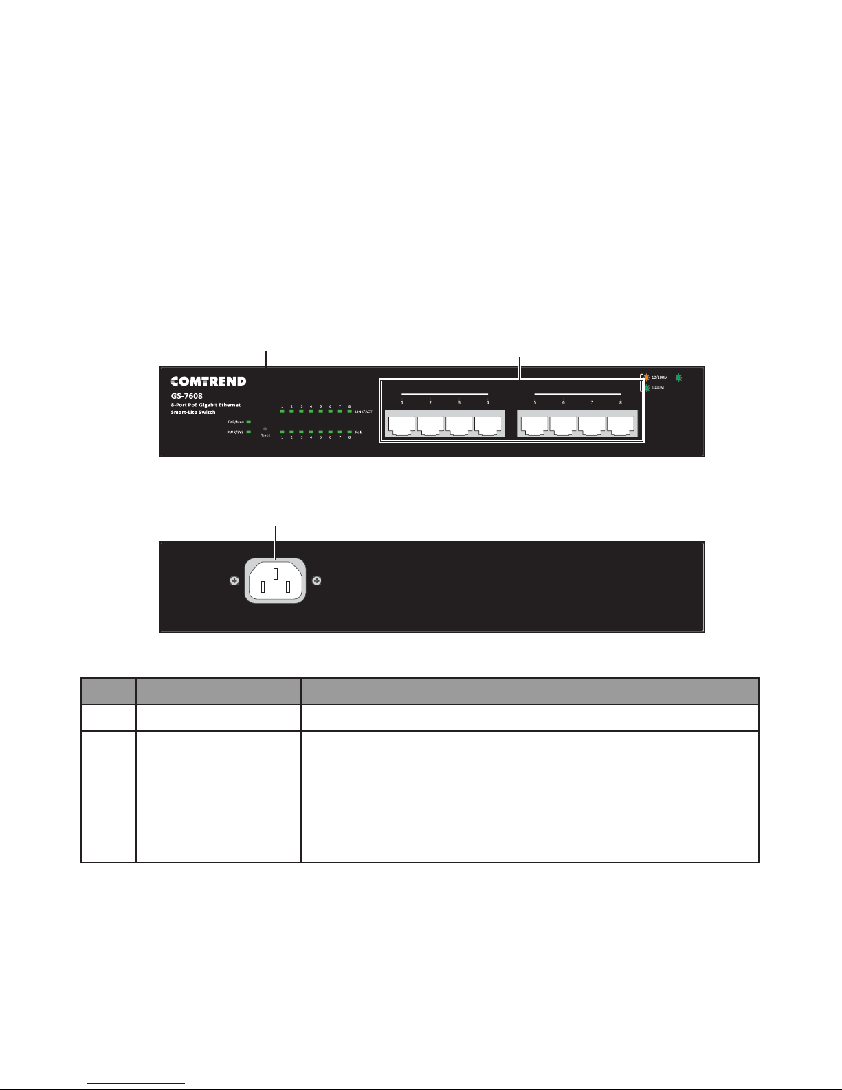
The following views apply to GS-7608.
1 2
Figure 1 - GS-7608 Front View
3
Figure 2 - GS-7608 Rear View
No.
Name
Description
1
Reset button
Press (10 sec.) to restore factory default parameters.
2
Ethernet (LAN)
ports
Designed to connect to network devices with a
bandwidth of 10Mbps, 100Mbps or 1000Mbps. Each has
a corresponding 10/100/1000Mbps LED.
PoE on eight ports (ports 1 through 8), compatible with
IEEE 802.3af, with 150W dedicated internal power.
3
AC power in
Supports AC 100 – 240V, 50-60Hz.
PoE$
PoE$$$$$$$$$
$
PoE$
$
!
!
$
$$$$$$$$$$$$$$$$$$$
$
AC LINE
100-240 VAC
50/60 Hz
Introduction
4
Reset
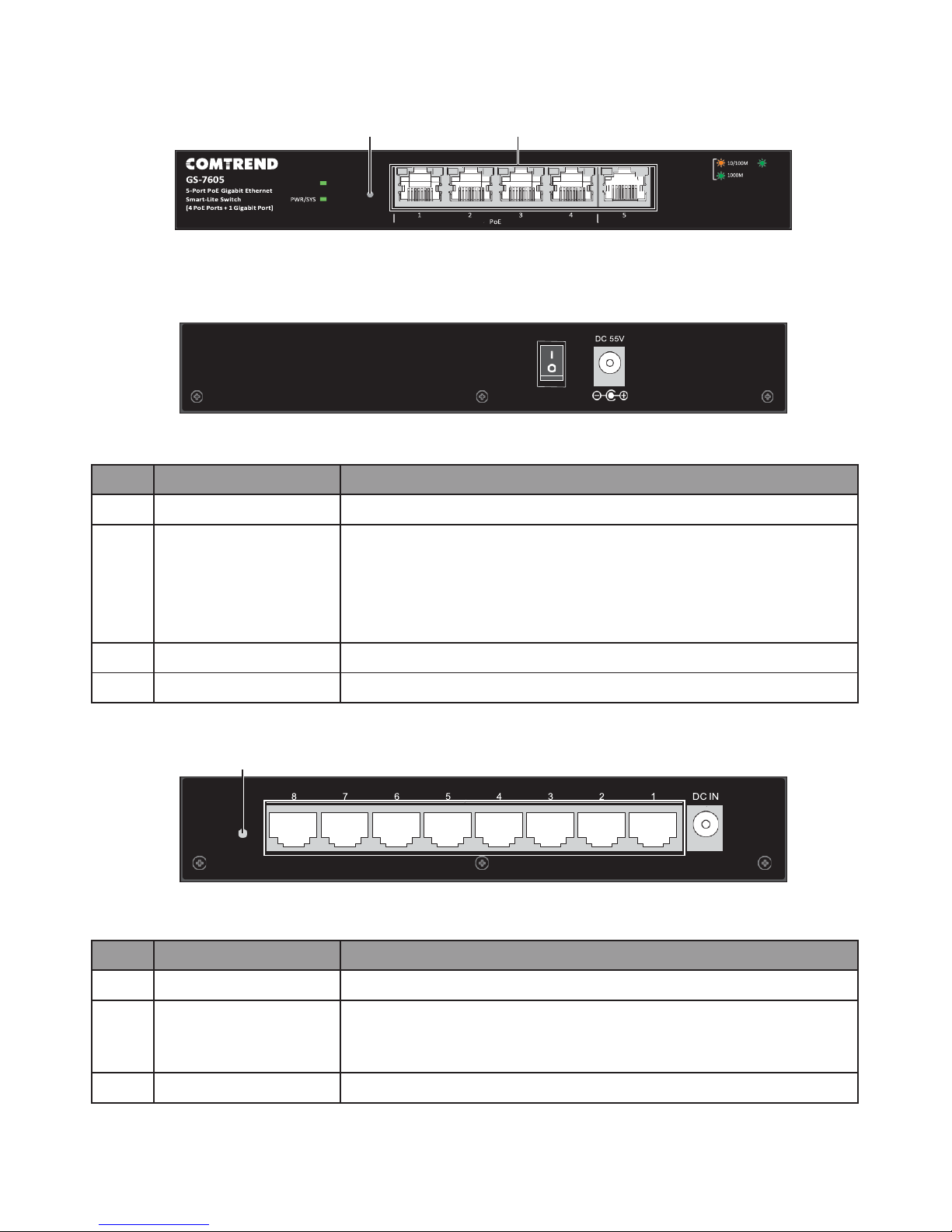
The following views apply to GS-7605.
1 2
Figure 3 - GS-7605 Front View
3 4
Figure 4 - GS-7605 Rear View
No.
Name
Description
1
Reset button
Press (10 sec.) to restore factory default parameters.
2
Ethernet (LAN)
ports
Designed to connect to network devices with a
bandwidth of 10Mbps, 100Mbps or 1000Mbps. Each has
a corresponding 10/100/1000Mbps LED.
PoE on four ports (ports 1 through 4), compatible with
IEEE 802.3af, with 150W dedicated internal power.
3
Power button
Press to power on or off the device.
4
DC power in
Supports 100 – 240V AC, 50/60 Hz.
The following view applies to GS-7408.
1 2 3
Figure 5 - GS-7408 Rear View
No.
Name
Description
1
Reset button
Press (10 sec.) to restore factory default parameters.
2
Ethernet (LAN)
ports
Designed to connect to network devices with a
bandwidth of 10Mbps, 100Mbps or 1000Mbps. Each has
a corresponding 10/100/1000Mbps LED.
3
DC power in
Supports 5V DC/1A.
$
PoE$
!
!
!
$
PoE/Max$
$
Reset$
$$$$$
$
Introduction
5
Reset
$
$
PoE$
$
PoE$
PoE$
!
!
$
$$$$$$$
$
$$$
$
$
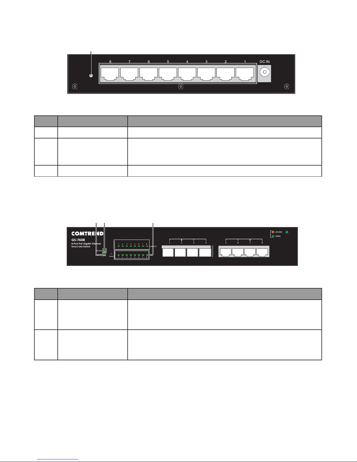
The following view applies to GS-7405.
1 2 3
Figure 6 - GS-7405 Rear View
No.
Name
Description
1
Reset button
Press (10 sec.) to restore factory default parameters.
2
Ethernet (LAN)
ports
Designed to connect to network devices with a
bandwidth of 10Mbps, 100Mbps or 1000Mbps. Each has
a corresponding 10/100/1000Mbps LED.
3
DC power in
Supports 5V DC/1A.
1.4.2. LED Indicators
The following view applies to GS-7608.
1 2 3 4
Figure 7 - GS-7608 LED Indicators
No.
Name
Description
1
Power/System
•
Off: power off
•
On: power on, system ready
•
Blinking: system boot-up
2
PoE Max
Green LED
•
Off: PoE power output under 120W PoE power budget
•
PoE power output over 120W PoE power budget

Introduction
6
No.
Name
Description
3
Port LED
LINK/ACT bi-color LED:
•
Off: port disconnected or link fail
•
Green on: 1000M connected
•
Amber on: 10/100M connected
•
Blinking: sending or receiving data
4
PoE LED
Green LED:
•
Off: PoE power output off
•
On: PoE power output on
The following view applies to GS-7605.
1 2 3 4 3
Figure 8 - GS-7605 LED Indicators
No.
Name
Description
1
Power/System
Green LED:
•
Off: power off or fail
•
On: power on
•
Blinking: system boot-up
2
PoE Max
Green LED
•
Off: PoE power output under 55W PoE power budget
•
On: PoE power output over 55W PoE power budget
3
Port LED
LINK/ACT bi-color LED:
•
Off: port disconnected or link fail
•
Green on: 1000M connected, PoE power output on
•
Amber on: 10/100M connected
•
Blinking: sending or receiving data
4
PoE LED
Green LED:
•
Off: PoE power output off
•
On: PoE power output on
$
$
!
!
!
$
PoE/Max$
PWR/SYS$
Reset$
$$$$$
$
Introduction
7
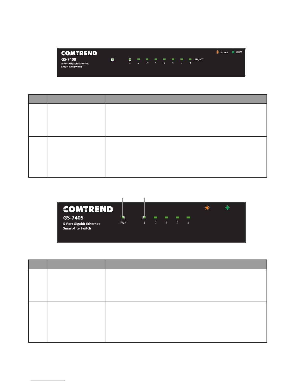
The following view applies to GS-7408.
1 2
Figure 9 - GS-7408 LED Indicators
No.
Name
Description
1
Power
Green LED:
•
Off: power off or fail
•
On: power on
•
Blinking: system boot-up
2
Port LED
LINK/ACT bi-color LED:
•
Off: port disconnected or link fail
•
Green on: 1000M connected, PoE power output on
•
Amber on: 10/100M connected
•
Blinking: sending or receiving data
The following view applies to GS-7405.
1 2
Figure 10 - GS-7405 LED Indicators
No.
Name
Description
1
Power
Green LED:
•
Off: power off or fail
•
On: power on
•
Blinking: system boot-up
2
Port LED
LINK/ACT bi-color LED:
•
Off: port disconnected or link fail
•
Green on: 1000M connected, PoE power output on
•
Amber on: 10/100M connected
•
Blinking: sending or receiving data
$
$
!
!
$
PWR$$$$$$$$$
10/100M$
1000M
$
!
!
LINK/ACT$
$$$$$
$

Installation
8
2. Installation
This chapter describes how to install and connect your Comtrend Switch. Read the
following topics and perform the procedures in the correct order. Incorrect installation
may cause damage to the product.
All models are designed for desktop use, however, the GS-7608 is available with a
rackmount kit.
2.1. Placement Tips
•
Ambient Temperature—To prevent the switch from overheating, do not operate it
in an area that exceeds an ambient temperature of 122°F (50°C).
•
Air Flow—Be sure that there is adequate air flow around the switch.
•
Mechanical Loading—Be sure that the switch is level and stable to avoid any
hazardous conditions.
•
Circuit Overloading—Adding the switch to the power outlet must not overload
that circuit.
2.2. Desktop Installation
To place the switch on a desktop:
1. Install the four rubber feet (included) on the bottom of the switch.
2. Place the switch on a flat surface.
Figure 11 - Desktop Installation

Installation
9
2.3. Rackmount Installation
Only the following device is designed for a rack mount installation: GS-6708.
You can mount the switch in any standard size, 19-inch (about 48 cm) wide rack. The
switch requires 1 rack unit (RU) of space, which is 1.75 inches (44.45 mm) high.
To place the switch on a standard rack (1 rack unit high):
For stability, load the rack from the bottom to the top, with the heaviest
devices on the bottom. A top-heavy rack is likely to be unstable and may tip
over.
When mounting smaller switch products into a standard 19-inch rack, a pair
of extension brackets (sometimes referred to as ears) are needed to adapt
the switch to the rack size.
These extension brackets are mounted on the switch using the screws
provided in the kit, and have two holes that are used to then screw the
switch into the rack.
An example of one type of these extension brackets is shown in the following
figure.
A common problem that occurs during rack mounting is the distance between
the screw holes on the rack. Some racks are made with a uniform distance
between all of the holes, and others have the holes organized into groups
(see photo on the next page for an example).
When organized into groups, the switch must be placed in the rack so that
the holes in the extension brackets line up correctly.
1. Align the mounting brackets with the mounting holes on the switch’s side panels
and secure the brackets with the screws provided.
Figure 12 - GS-6708 Bracket Installation

Installation
10
2. Secure the switch on the equipment rack with the screws provided.
Figure 13 - Switch on a Rack Installation
Getting Started
11
3. Getting Started
This section provides an introduction to the web-based configuration utility, and
covers the following topics:
•
Powering on the device
•
Connecting to the network
•
Power over Ethernet (PoE) considerations
•
Starting the web-based configuration utility
3.1. Power
3.1.1. Installing Power
Power down and disconnect the power cord before servicing or wiring a
switch.
Do not disconnect modules or cabling unless the power is first switched off.
The device only supports the voltage outlined in the type plate. Do not use
any other power components except those specifically designated for the
switch.
Disconnect the power cord before installation or cable wiring.
The Gigabit Ethernet Smart-Lite switches are available with different power options
from an internal (72W) PSU to an external (150W) option and power adapters (5V
DC/1A). It is recommended to connect the switch with a single-phase three-wire
power source with a neutral outlet, or a multifunctional computer professional source.
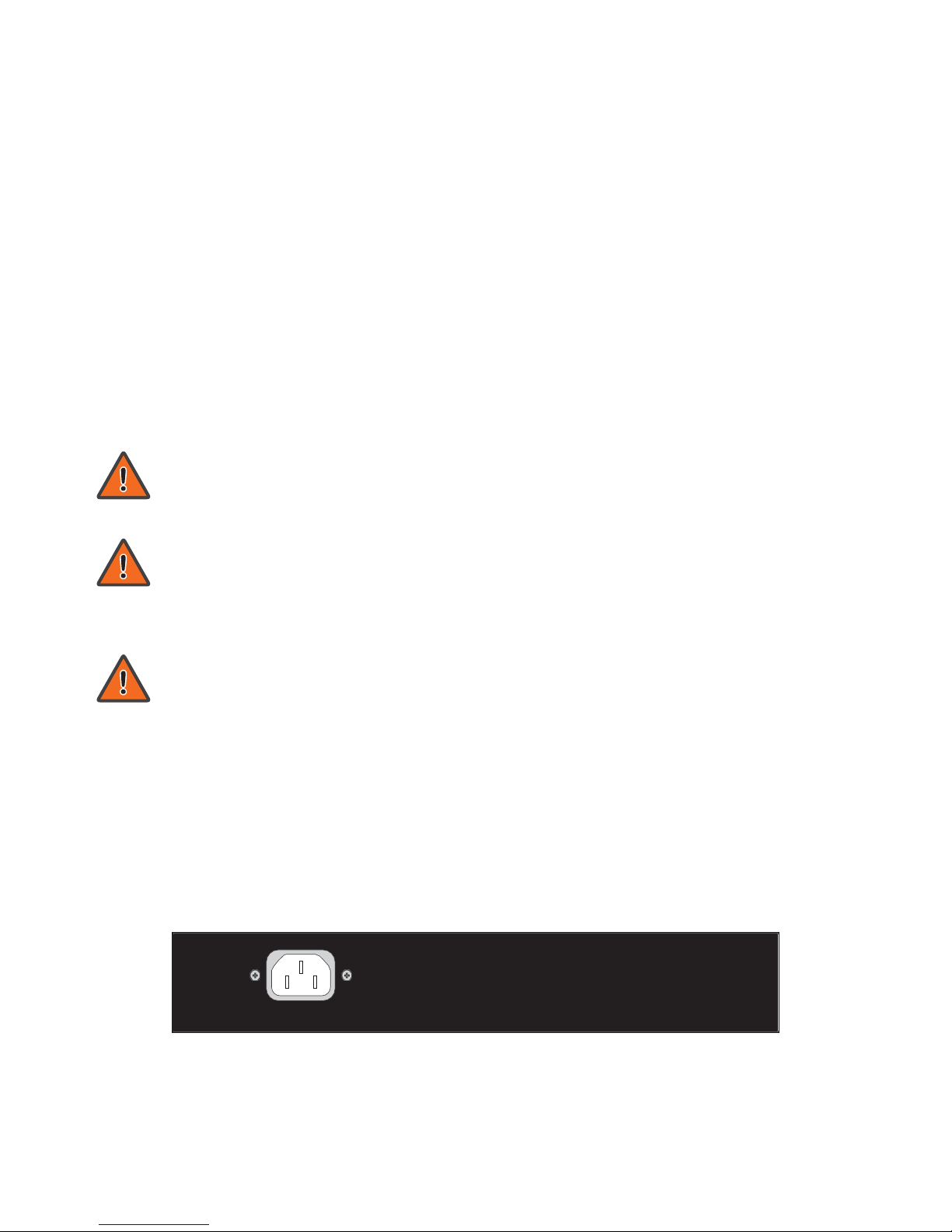
Connect the AC power connector on the back panel of the switch to the external
power source with the included power cord, and check the power LED is on. The
following figure illustrates the power socket location on the rear side of a GS-7608
switch. See “1.4.1. Switch Views” on page 3 for power socket location on your
model.
Figure 14 - GS-7608 Rear View, AC Power Socket
AC LINE
100-240 VAC
50/60 Hz
Getting Started
12
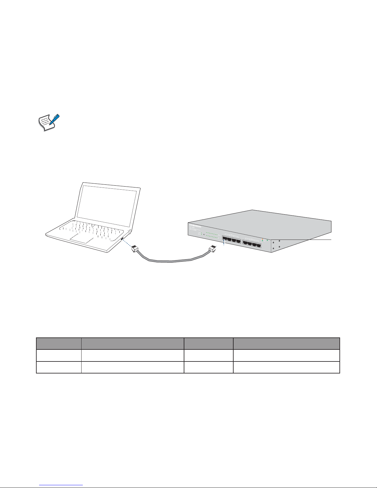
3.1.2. Connecting to the Network
To connect your switch to the network:
1. Connect an Ethernet cable to the Ethernet port of a computer, printer, network
storage, or other network devices.
2. Connect the other end of the Ethernet cable to one of the numbered Ethernet
ports of the switch. The LED of the port lights if the device connected is active.
3. Repeat Step 1 and Step 2 for each device that you want to connect to the switch.
We strongly recommend using CAT-5E or better cable to connect network
devices. When you connect your network devices, do not exceed the
maximum cabling distance of 100 meters (328 feet). It can take up to
one minute for attached devices or the LAN to be operational after it is
connected. This is normal behavior.
Switch ports will automatically adjust to the characteristics (MDI/MDI-X, speed,
duplex) of the device to which the switch is connected.
Figure 15 - PC Connect
3.1.3. Power over Ethernet (PoE) Considerations
For PoE switch models, consider the following information:
Devices considered a Power Sourcing Equipment (PSE), can deliver a maximum of 30
Watts per PoE port.
Model
Power Dedicated to PoE
PoE Ports
PoE Standard Supported
GS-7605
65W
1 to 5
IEEE802.3at/af
GS-7608
130W
1 to 8
IEEE802.3at/af

Getting Started
13
When connecting switches capable of supplying PoE, consider the following
information:
•
Switch models with PoE function are PSEs. These models are capable of
supplying DC power to attached PDs, such as VoIP phones, IP cameras,
and wireless access points (APs). PoE switches. Additionally, PoE switches
are capable of detecting and supplying power to pre-standard legacy PoE
Power Devices. Due to the support for legacy PoE, there is a possibility
that PoE switches acting as a PSE may inadvertently detect and supply
power an attached PSE, including other PoE switches. This false detection
may result in a PoE switch operating improperly and unable to supply
power to attached PDs.
•
The prevention of a false detection can be easily remedied by disabling
PoE on the ports that are used to connect PSEs. Another simple practice
to prevent a false detection is to first power up a PSE device before
connecting it to a PoE switch.
•
When a device is falsely detected as a PD, disconnect the device from the
PoE port and power recycle the device with AC power before reconnecting
it to the PoE port.

Getting Started
14
3.2. Starting the Web-based Configuration Utility
This section describes how to navigate the web-based switch configuration utility.
If you are using a pop-up blocker, make sure it is disabled.
3.2.1. Browser Restrictions
•
If you are using older versions of Internet Explorer, you cannot directly use an
IPv6 address to access the device. You can, however, use the DNS (Domain
Name System) server to create a domain name that contains the IPv6 address,
and then use that domain name in the address bar in place of the IPv6 address.
•
If you have multiple IPv6 interfaces on your management station, use the IPv6
global address instead of the IPv6 link local address to access the device from
your browser.
3.2.2. Launching the Configuration Utility
To open the web-based configuration utility:
1. Open a Web browser.
2. Enter the IP address of the device you are configuring in the address bar on the
browser (the factory default IP address is 192.168.169.1) and then press Enter.
When the device is using the factory default IP address of 192.168.169.1,
its power LED flashes continuously. When the device is using a DHCP
assigned IP address or an administrator-configured static IP address, the
power LED is on solid. Your computer’s IP address must be in the same
subnet as the switch. For the default IP address this is any IP address in the
range 192.168.169.x (x = 2 – 254). You can modify the IP address of your
computer if you need.
The login window displays.
Figure 16 - Login Window
Getting Started
15
3.2.3. Logging In
The default username is admin and the default password is admin. The first time that
you log in with the default username and password, you are required to enter a new
password.
To log in to the device configuration utility:
1. Enter the default user ID (admin) and the default password (admin).
2. If this is the first time that you logged on with the default user ID (admin) and
the default password (admin) it is recommended that you change your password
immediately. See “4.2.1. Password” on page 33 for additional information.
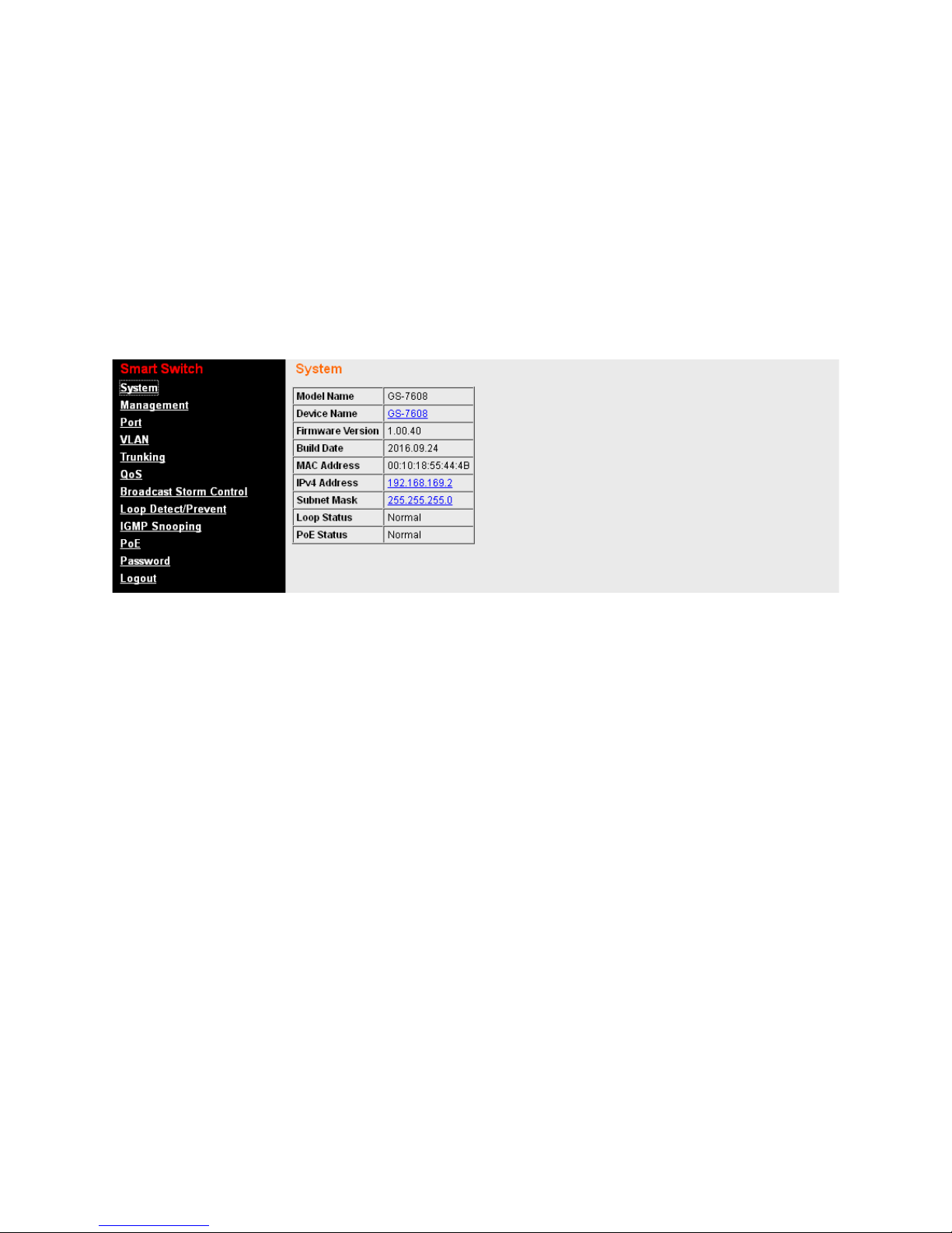
When the login attempt is successful, the System Status window displays.
Figure 17 - System Status
If you entered an incorrect username or password, an error message appears and the
Login page remains displayed on the window. If you are having problems logging in,
please see the Launching the Configuration Utility section in the Administration Guide
for additional information.
3.2.4. Logging Out
By default, the application logs out after ten minutes of inactivity.
To logout, click Logout in the top right corner of any page. The system logs out of the
device.
When a timeout occurs or you intentionally log out of the system, a message appears
and the Login page appears, with a message indicating the logged-out state. After
you log in, the application returns to the initial page.

Web-based Switch Configuration
16
4. Web-based Switch Configuration
The PoE Smart-Lite switch software provides rich Layer 2 functionality for switches
in your networks. This chapter describes how to use the web-based management
interface (Web UI) to configure the switch’s features.
For the purposes of this manual, the user interface is separated into two sections, as
shown in the following figure:
2
1
Figure 18 - User Interface
No.
Name
Description
1
Configuration
menu
Navigate to locate specific switch functions.
2
Configuration
settings
Edit specific function settings.
Web-based Switch Configuration
17
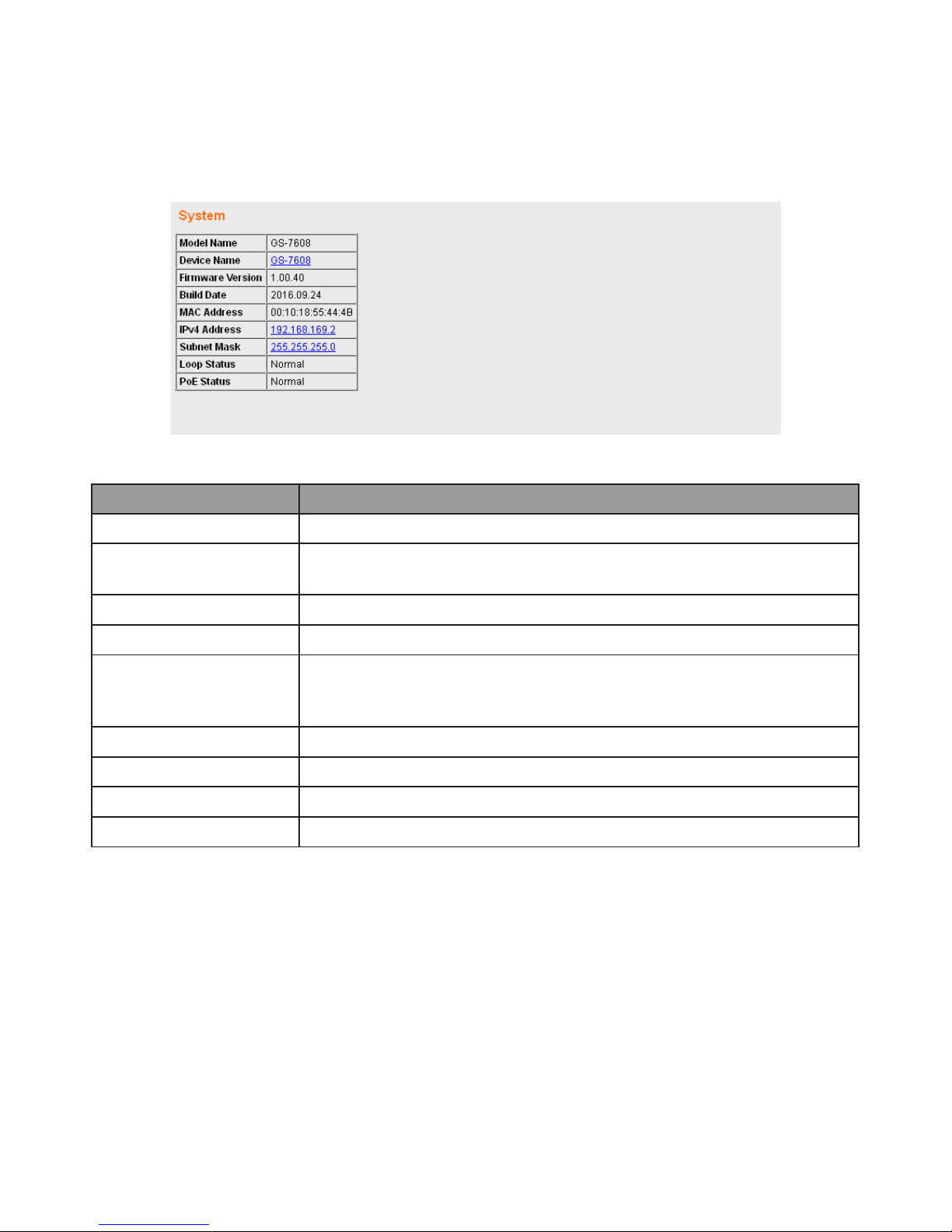
4.1. System
Use this page to view status information such as Device Name, MAC address, IP
Address and PoE status.
To view the System menu, navigate to System.
Figure 19 - System
Item
Description
Model Name
Switch model name.
Device Name
System name of the switch, configurable according to user
preference.
Firmware Version
Current firmware version of the device.
Build Date
Device production date.
MAC Address
A unicast MAC address for which the switch has forwarding
and/or filtering information. The format is a six-byte MAC
address, with each byte separated by colons.
IPv4 Address
Switch IPv4 address on the network.
Subnet Mask
A 32-bit number that masks an IP address.
Loop Status
Displays whether or not loops exist in the network.
PoE Status
Displays the Power over Ethernet (PoE) status.
Web-based Switch Configuration
18
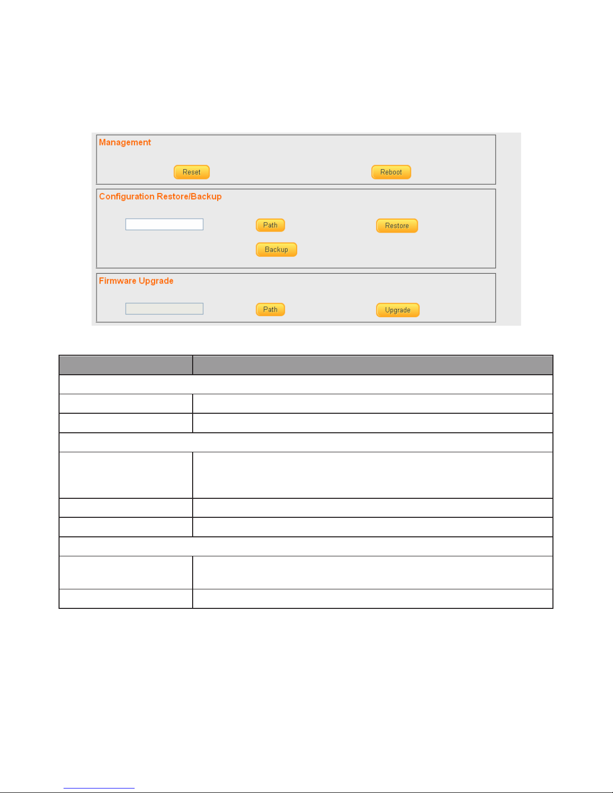
4.1.1. Management
Use this page to reset the switch to original factory default settings, reboot the
switch, backup and restore switch settings, and upgrade firmware.
To view the Management menu, navigate to Management.
Figure 20 - Management
Item
Description
Management
Reset
Restore switch to original factory default settings.
Reboot
Reboot switch.
Configuration Restore/Backup
Path
Click to browse a remote TFTP server or on local storage,
to locate a file with a previously saved switch setting
configuration.
Restore
Install selected switch setting configuration file.
Backup
Save current switch setting configuration as a backup file.
Firmware Upgrade
Path
Click to browse a remote TFTP server or on local storage, to
locate a firmware file.
Upgrade
Install selected firmware file.
Web-based Switch Configuration
19
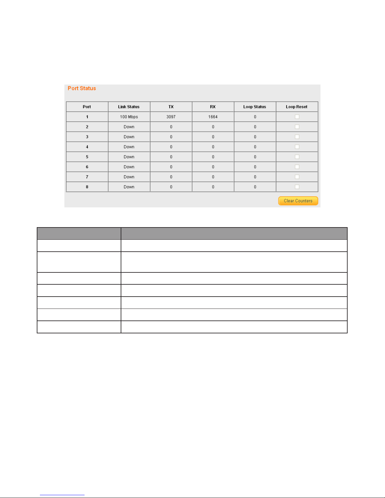
4.1.2. Port
Use this page to view traffic information such as Link Status, TX, RX, Loop Status and
Loop Reset, on each port. The tracking data on each port can also be reset.
To view the Port menu, navigate to Port.
Figure 21 - Port
Item
Description
Port
Designated port number.
Link Status
Displays whether or not port is in use, and link speed if it is
in use.
TX
The total number of packets transmitted by the port.
RX
The total number of packets received by the port.
Loop Status
Displays whether or not loops are detected.
Loop Reset
Click to reset loop status.
Clear Counters
Click to reset tracking data.
Web-based Switch Configuration
20
4.1.3. VLAN
Use this section to create and modify VLANs.
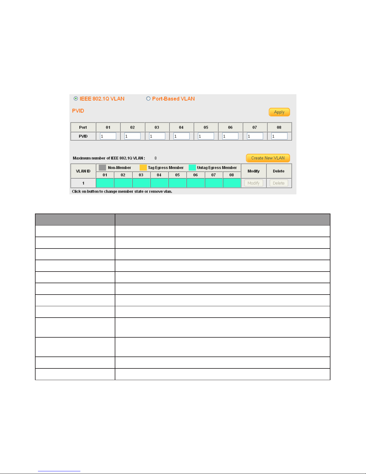
IEEE 802.1Q VLAN
To view the IEEE 802.1Q VLAN menu, navigate to VLAN > IEEE 802.1Q VLAN.
Figure 22 - VLAN > IEEE 802.1Q VLAN
Item
Description
IEEE 802.1Q VLAN
Click to enter IEEE 802.1Q VLAN settings.
Port-Based VLAN
Click to enter port-based VLAN settings.
Apply
Click Apply to save the values and update the screen.
Port
Designated port number.
PVID
Enter a VLAN ID for each port.
Create New VLAN
Click Create New VLAN to enter new VLAN settings.
VLAN ID
Virtual LAN ID.
Non-Member
Port is not a member of a VLAN.
Tag Egress Member
Tag outgoing packets of a port which is a member of the
VLAN.
Untag Egress
Member
Untag outgoing packets of a port which is a member of the
VLAN.
Modify
Modify port settings of a specific VLAN.
Delete
Delete a specific VLAN.
Web-based Switch Configuration
21
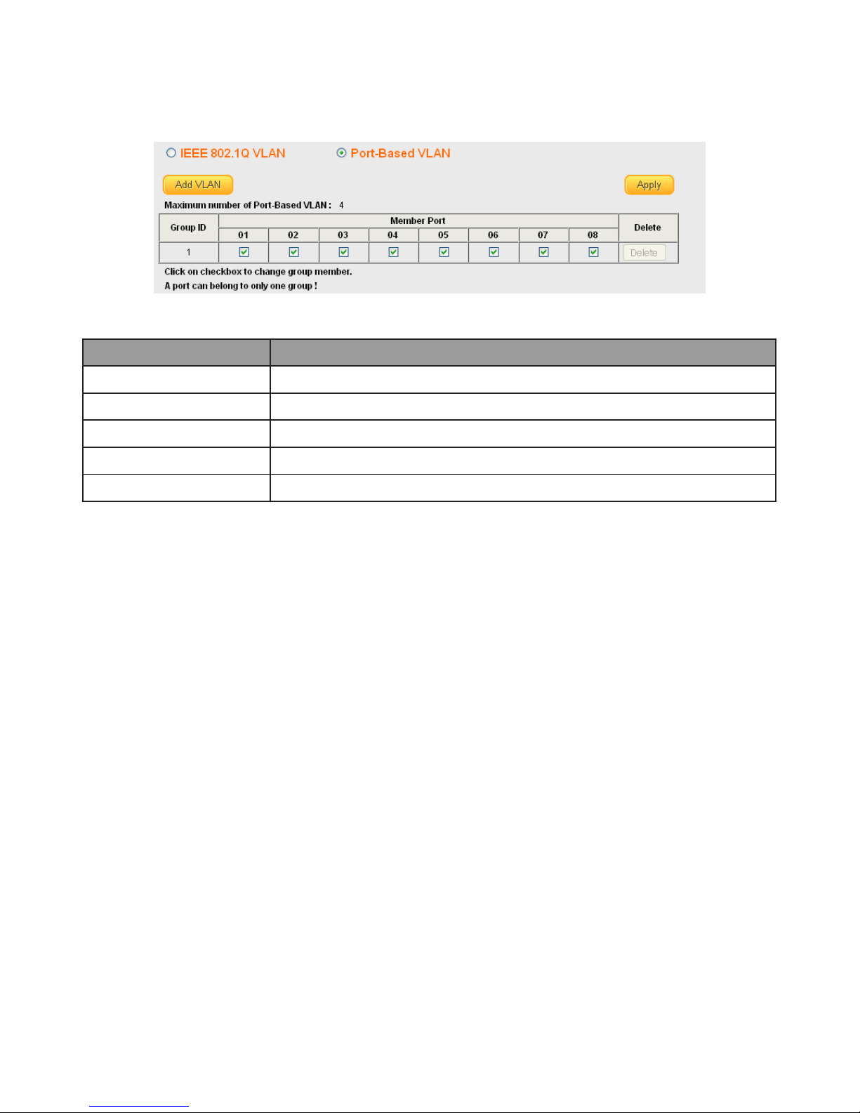
Port-Based VLAN
To view the Port-Based VLAN menu, navigate to VLAN > Port-Based VLAN.
Figure 23 - VLAN > Port-Based VLAN
Item
Description
Add VLAN
Click Add VLAN to enter new VLAN settings.
Apply
Click Apply to save the values and update the screen.
Member Port
Click to assign specific ports as members of a VLAN.
Group ID
Identifier of the group of ports in a VLAN.
Delete
Delete a specific VLAN.

Web-based Switch Configuration
22
4.1.4. Trunking
Use this option to aggregate multiple Ethernet ports together to form a logical port.
This feature supports static allocation and Link Aggregation Control Protocol (LACP).
To view the Trunking menu, navigate to Trunking.
Figure 24 - Trunking
Item
Description
Apply
Click Apply to save the values and update the screen.
LACP Global State
Enable/disable LCAP.
Link Aggregation
Algorithm
Select a link aggregation algorithm:
•
MAC SA & DA
•
MAC DA
•
MAC SA
Link Group Activity
Select link group activity status:
•
Passive
•
Active
Link Group Members
The ports that are members of a port channel.
Web-based Switch Configuration
23
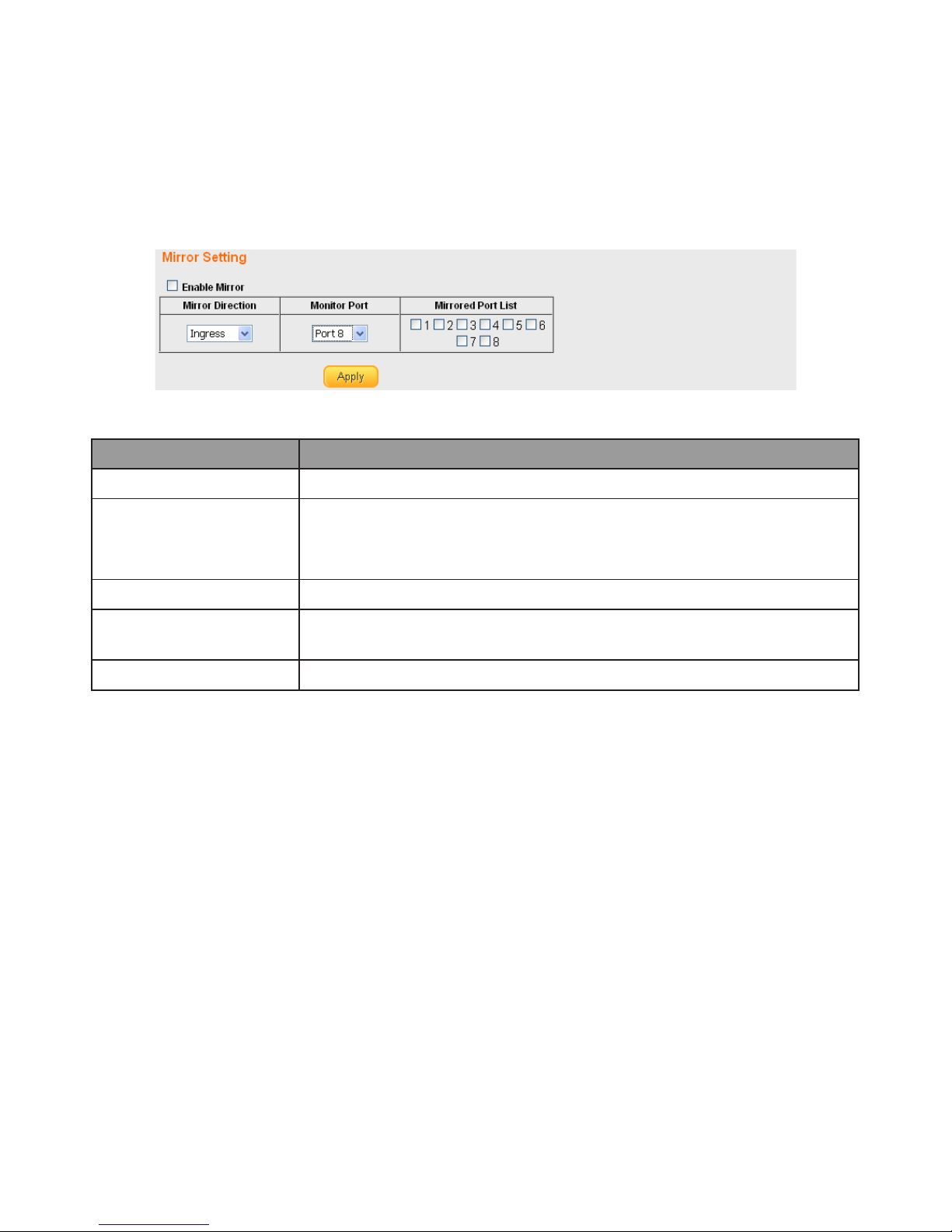
4.1.5. Mirror
Port mirroring selects the network traffic for analysis by a network analyzer. This is
done for specific ports of the switch. As such, many switch ports are configured as
source ports and one switch port is configured as a destination port. At the time of
printing, this feature is only available for GS-7405 and GS-7408.
To view the Mirror menu, navigate to Mirror.
Figure 25 - Mirror
Item
Description
Enable Mirror
Enable/disable port mirroring.
Mirror Direction
Select the mirror direction:
•
Ingress
•
Egress
Monitor Port
Select the mirror destination port.
Mirrored Port List
The ports or configured to mirror traffic to the destination.
Multiple source ports can be configured.
Apply
Click Apply to save the values and update the screen.

Web-based Switch Configuration
24
4.1.6. QoS
Use this section to configure Quality of Service (QoS) settings.
Disable QoS
To view the Disable QoS menu, navigate to QoS > Disable QoS.
Figure 26 - QoS > Disable QoS
Item
Description
Disable QoS
Enable/disable QoS.
Port-Based QoS
Click to select port-based QoS settings.
IEEE 802.1p QoS
Click to enter IEEE 802.1Q QoS settings.
Port-Based QoS
To view the Port-Based QoS menu, navigate to QoS > Port-Based QoS
Figure 27 - QoS > Port-Based QoS
Item
Description
Disable QoS
Enable/disable QoS.
Port-Based QoS
Click to select port-based QoS settings.
IEEE 802.1p QoS
Click to enter IEEE 802.1Q QoS settings.

Web-based Switch Configuration
25
Item
Description
Port
Designated port number.
Weight
Queue priority value. More packets are sent from a queue
with a higher weight value.
Queue 0-3
Queues used to store traffic until it can be processed or
serialized.
IEEE 802.1p QoS
To view the IEEE 802.1p QoS menu, navigate to QoS > IEEE 802.1p QoS.
Figure 28 - QoS > IEEE 802.1p QoS
Item
Description
Disable QoS
Enable/disable QoS.
Port-Based QoS
Click to select port-based QoS settings.
IEEE 802.1p QoS
Click to enter IEEE 802.1Q QoS settings.
Port
Designated port number.
Weight
Queue priority value. More packets are sent from a queue
with a higher weight value.
Queue 0-3
Queues used to store traffic until it can be processed or
serialized.
Web-based Switch Configuration
26
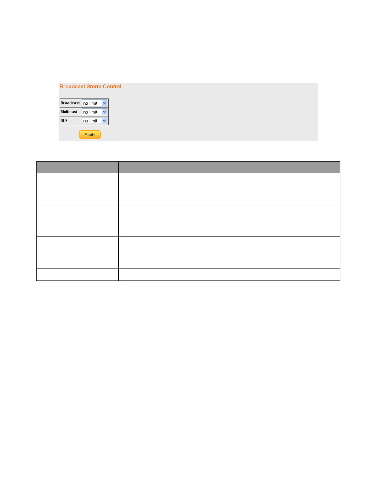
4.1.7. Broadcast Storm Control
This page allows you to set ingress port monitoring. At the time of writing, multicast
and DLF storm control features are only available for GS-7408.
To view the Broadcast Storm Control menu, navigate to Broadcast Storm Control.
Figure 29 - Broadcast Storm Control
Item
Description
Broadcast
Set Broadcast storm control limit:
•
no limit
• 512K/s to 512M/s
Multicast
Set Multicast storm control limit:
•
no limit
• 512K/s to 512M/s
DLF
Set DLF storm control limit:
•
no limit
• 512K/s to 512M/s
Apply
Click Apply to save the values and update the screen.

Web-based Switch Configuration
27
4.1.8. Rate Limiting
This page allows you to display and configure ingress and egress port monitoring
settings. At the time of writing this feature was only available for GS-7408.
Rate Limiting
This page displays ingress and egress port limits.
To view the Rate Limiting menu, navigate to Rate Limiting.
Figure 30 - Rate Limiting
Item
Description
Port
Designated port number. Click individual port numbers to
enter rate limit configuration menu for each port.
Ingress rate
The upper limit on how much traffic can enter a port.
Egress rate
The upper limit on how much traffic can exit a port.
Web-based Switch Configuration
28
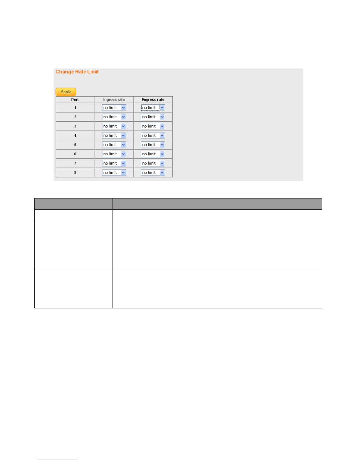
Change Rate Limit
Use this page to configure ingress and egress rate limit settings.
To view the Change Rate Limit menu, navigate to Rate Limiting > port number.
Figure 31 - Rate Limiting > port number
Item
Description
Apply
Click Apply to save the values and update the screen.
Port
Designated port number.
Ingress rate
Select to configure the upper limit on how much traffic can
enter a port:
•
no limit
• 512K/s to 512M/s
Egress rate
Select to configure the upper limit on how much traffic can
exit a port:
•
no limit
• 512K/s to 512M/s

Web-based Switch Configuration
29
4.1.9. Loop Detect/Prevent
Use this section to enable/disable and configure network routing loop detection.
Select settings from the drop down menu. At the time of writing this feature was only
available for GS-7608, GS-7408 and GS-7405.
To view the Loop Detection/Prevention menu, navigate to Loop Detection/Prevention.
Figure 32 - Network > Loop Detection
Item
Description
Off
Disable loop detection and prevention.
Loop Detection
Enable loop detection.
Loop Prevention
Enable loop prevention
Apply
Click Apply to save the values and update the screen.

Web-based Switch Configuration
30
4.1.10. IGMP Snooping
Use this section to create an IGMP Snooping Profile. Internet Group Management
Protocol (IGMP) Snooping is a feature that allows a switch to forward multicast traffic
intelligently on the switch. Multicast IP traffic is traffic that is destined to a host group.
Host groups are identified by class D IP addresses, which range from 224.0.0.0 to
239.255.255.255. Based on the IGMP query and report messages, the switch forwards
traffic only to the ports that request the multicast traffic. This prevents the switch
from broadcasting the traffic to all ports and possibly affecting network performance.
To view the IGMP Snooping menu, navigate to IGMP Snooping.
Figure 33 - IGMP Snooping
Item
Description
Enable IGMP
Snooping
Enable/disable IGMP snooping.
IGMP Static Router
Port
Select a static port on which to snoop, either No Static
Router Port, or one of ports 1-8.
Apply
Click Apply to save the values and update the screen.
Web-based Switch Configuration
31
4.2. PoE
Use this section to configure PoE settings for the switch and its ports. This feature is
only available for GS-7605 and GS-7608.
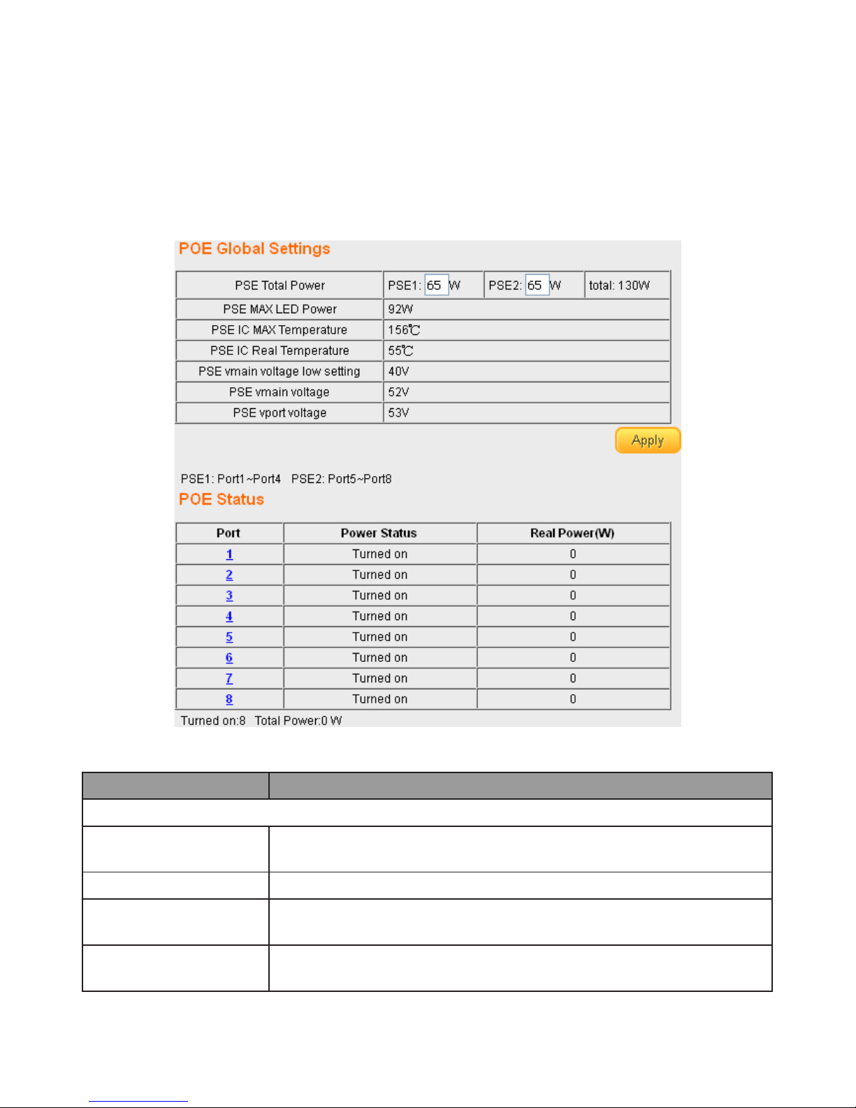
PoE Global Settings and PoE Status
To view the PoE Global Settings and PoE Status menu, navigate to PoE.
Figure 34 - PoE Menu
Item
Description
PoE Global Settings
PSE Total Power
Enter values for PSE1 and PSE2, for a total PSE power which
must not exceed 130W.
PoE MAX LED Power
Displays the maximum power supplied to LEDs.
PSE IC Max
Temperature
Displays upper IC temperature limit which will trigger
temperature protection activity.
PSE IC Real
Temperature
Displays the actual IC temperature.
Web-based Switch Configuration
32
Item
Description
PSE vmain voltage
low setting
Displays the lower limit for the PSE main voltage.
PSE vmain voltage
Displays the real PSE main voltage.
PSE vport voltage
Displays voltage supplied to ports.
Apply
Click Apply to save the values and update the screen.
PoE Status
Port
Designated port number. Click individual port numbers to
enter PoE port configuration menu for each port.
Power Status
Displays current port power status, on or off.
Real Power (W)
Displays power drawn by the port, in Watts.
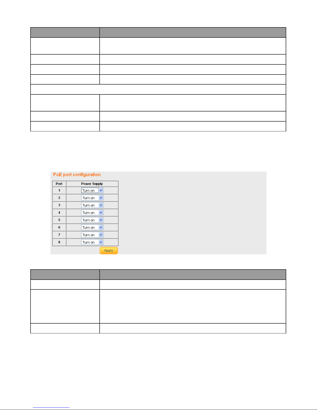
PoE Port Configuration
To view the PoE Port Configuration menu, navigate to PoE > PoE Status and click on
an individual port number.
Figure 35 - PoE > PoE Status > Port Number
Item
Description
Port
Designated port number.
Power Supply
Use the drop down menu to select port power supply
options:
•
Turn on
•
Turn off
Apply
Click Apply to save the values and update the screen.

Web-based Switch Configuration
33
4.2.1. Password
Use these settings to change an account password.
To view the Password menu, navigate to Password.
Figure 36 - Password
Item
Description
Confirm
Click Confirm to save the values and update the screen.
Old Password
Enter current password.
New Password
Enter new password.
Confirm New
Password
Enter new password again to confirm.
4.2.2. Logout
Click Logout to leave the switch management menu and close the web management
session.

Federal Communication Commission Interference Statement
34
5. Federal Communication Commission
Interference Statement
This equipment has been tested and found to comply with the limits for a Class B
digital device, pursuant to Part 15 of FCC Rules. These limits are designed to provide
reasonable protection against harmful interference in a residential installation. This
equipment generates, uses, and can radiate radio frequency energy and, if not
installed and used in accordance with the instructions, may cause harmful interference
to radio communications. However, there is no guarantee that interference will not
occur in a particular installation. If this equipment does cause harmful interference to
radio or television reception, which can be determined by turning the equipment off
and on, the user is encouraged to try to correct the interference by one or more of the
following measures:
1. Reorient or relocate the receiving antenna.
2. Increase the separation between the equipment and receiver.
3. Connect the equipment into an outlet on a circuit different from that to which the
receiver is connected.
4. Consult the dealer or an experienced radio technician for help.
Safety
This equipment is designed with the utmost care for the safety of those who install
and use it. However, special attention must be paid to the dangers of electric shock
and static electricity when working with electrical equipment. All guidelines of this and
of the computer manufacture must therefore be allowed at all times to ensure the
safe use of the equipment.
FCC Caution
This device and its antenna must not be co-located or operating in conjunction
with any other antenna or transmitter. This device complies with Part 15 of the FCC
Rules. Operation is subject to the following two conditions: (1) this device may
not cause harmful interference, and (2) this device must accept any interference
received, including interference that may cause undesired operation. Any changes or
modifications not expressly approved by the party responsible for compliance could
void the authority to operate equipment.
FCC Radiation Exposure Statement
This equipment complies with FCC radiation exposure limits set forth for an
uncontrolled environment. This equipment should be installed and operated with
minimum distance 20cm between the radiator & your body.

Federal Communication Commission Interference Statement
35
R&TTE Compliance Statement
This equipment complies with all the requirements of DIRECTIVE 1999/5/EC OF THE
EUROPEAN PARLIAMENT AND THE COUNCIL of March 9, 1999 on radio equipment and
telecommunication terminal equipment and the mutual recognition of their conformity
(R&TTE). The R&TTE Directive repeals and replaces in the directive 98/13/EEC
(Telecommunications Terminal Equipment and Satellite Earth Station Equipment) As of
April 8, 2000.
EU Countries Intended for Use
The ETSI version of this device is intended for home and office use in Austria,
Belgium, Bulgaria, Cyprus, Czech, Denmark, Estonia, Finland, France, Germany,
Greece, Hungary, Ireland, Italy, Latvia, Lithuania, Luxembourg, Malta, Netherlands,
Poland, Portugal, Romania, Slovakia, Slovenia, Spain, Sweden, Turkey, and United
Kingdom. The ETSI version of this device is also authorized for use in EFTA member
states: Iceland, Liechtenstein, Norway, and Switzerland.
EU Countries Not Intended for Use
None
Protect Our Environment
When the equipment has reached the end of its useful life, it must
be taken to a recycling center and processed separate from domestic
waste.
The cardboard box, the plastic contained in the packaging, and the
parts that make up this switch can be recycled in accordance with
regionally established regulations. Never dispose of this electronic
equipment along with your household waste; you may be subject to
penalties or sanctions under the law.
 Loading...