

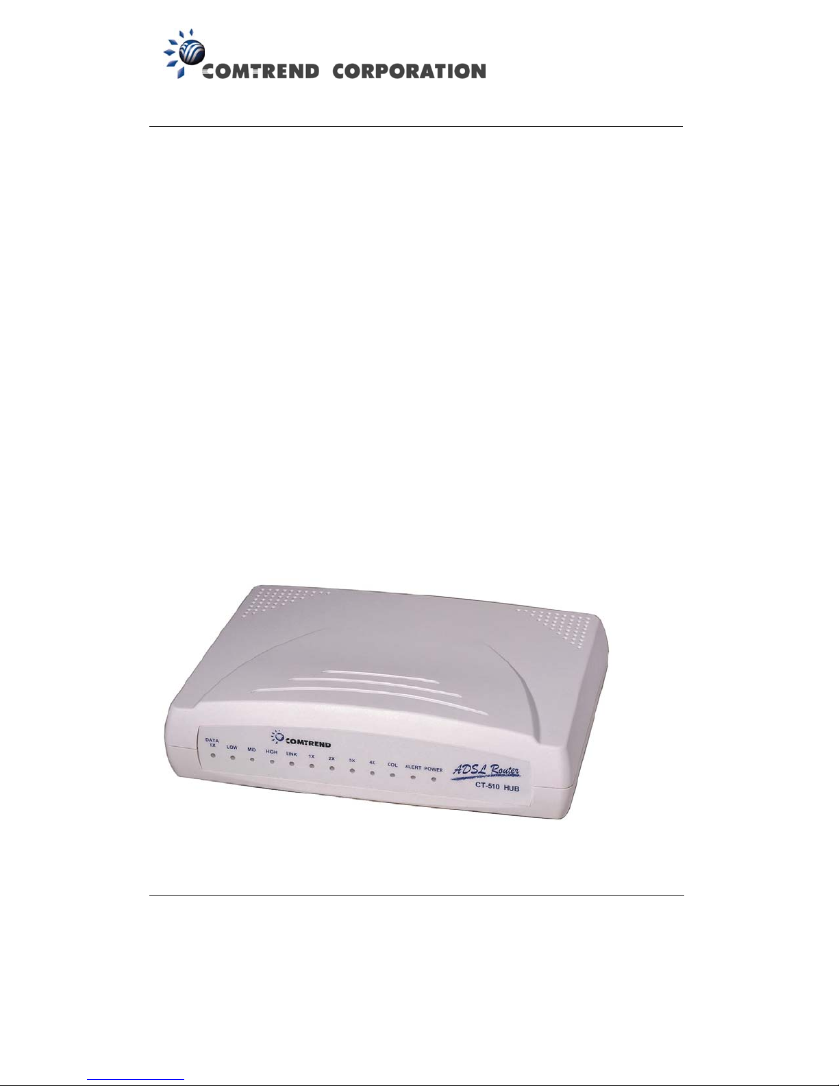
CT-510
ADSL Router
User Manual
Version A3.0, June 3, 2003
261028-002

Preface
This manual is designed to provide information to network administrators. It
covers the installation, operation and applications of the CT-510 ADSL router.
The reader is presumed to have a basic understanding of telecommunications.
For product updates, new product releases, manual revisions, software
upgrades, and technical support visit Comtrend Corporation at
http:\\www.comtrend.com.tw
Copyright
Copyright© 2000 Comtrend Corporation. All rights reserved. The information
and messages contained herein are proprietary to Comtrend Corporation. No
part of this guide may be translated, transcribed, reproduced, in any form, or
by any means without prior written permission by Comtrend Corporation.
i

Table of Content
CHAPTER 1 INTRODUCTION .........................................................6
1.1
1.2
1.3 Application ......................................................................... 8
CHAPTER 2 HARDWARE INSTALLATION .......................................9
2.1
2.1.1 Rear Panel Connectors ....................................................... 10
2.2 Preparing Installation......................................................... 11
2.3 Installation ....................................................................... 13
CHAPTER 3
3.1 Getting Started ................................................................. 14
3.2 How to access CT-510........................................................ 15
3.2.1 Console............................................................................ 15
3.2.2
Overview............................................................................ 6
Features ............................................................................ 7
Front Panel LED Indicators.................................................... 9
MANAGEMENT..........................................................14
Telnet.............................................................................. 16
3.2.3 Web ................................................................................ 18
3.3 General Configuration Steps in Console/Telnet ....................... 19
3.3.1
3.3.2
3.3.3 Keyboard Operations ......................................................... 22
CHAPTER 4 INITIAL CONFIGURATION (CONSOLE/TELNET)........23
4.1 Initial Setup ..................................................................... 23
4.1.1
4.1.2 CO Chipset ....................................................................... 23
4.1.3 ADSL Physical Mode........................................................... 24
4.1.4
Configuration Steps ........................................................... 19
Menu Layout..................................................................... 21
Bridge and Router Mode ..................................................... 23
Console Password Check .................................................... 24
ii

4.1.5 Console Session Timeout .................................................... 24
4.1.6 Login Name & Passwords.................................................... 24
4.2
4.2.1 LAN Interface ................................................................... 25
4.2.2 ATM Interface ................................................................... 26
4.2.3 ATM VC Parameters ........................................................... 27
4.2.4
4.2.5 ADSL Retrain .................................................................... 29
4.3 Basic Configuration............................................................ 29
4.4
CHAPTER 5
5.1 Overview.......................................................................... 31
5.2 Static Bridging Configuration............................................... 31
5.2.1
5.2.2
Quick Configuration ........................................................... 25
ISP.................................................................................. 28
ADSL Characteristics Parameters ......................................... 30
BRIDGING................................................................ 31
Add A Static MAC Entry ...................................................... 31
Delete a Static MAC Address ............................................... 32
5.2.3 List Static Bridging Parameters............................................ 32
5.3 Spanning Tree Protocol....................................................... 32
5.4
CHAPTER 6
6.1 RIP Configuration .............................................................. 33
6.2 Static Route Configuration .................................................. 34
6.2.1
6.2.2 Delete a Static Route ......................................................... 34
6.2.3 List Static Routes .............................................................. 34
6.3 Routing Table.................................................................... 34
6.4
CHAPTER 7 NETWORK & PORT ADDRESS TRANSLATION............................. 36
7.1 Overview.......................................................................... 36
Forwarding Table ............................................................... 32
IP ROUTING............................................................. 33
Add a Static Route............................................................. 34
Ping Test Utility ................................................................. 35
iii

7.2 Enable PAT/NAT................................................................. 36
7.3 PAT Virtual Server ............................................................. 37
7.3.1
7.3.2 Delete Virtual Server.......................................................... 38
7.3.3 List Virtual Server Entry ..................................................... 38
7.4 Configure NAT/PAT IP Pools................................................. 38
7.4.1
7.4.2 Global IP Address .............................................................. 39
7.4.3 Private/Global IP Pool Mapping ............................................ 39
7.4.4 Fixed NAT IP Mapping ........................................................ 40
CHAPTER 8 DNS PROXY.............................................................. 41
Add Virtual Server Entry..................................................... 37
Private IP Address ............................................................. 39
Add a Pool Translation ........................................................ 39
Delete a NAT/PAT Pool Translation........................................ 40
List NAT/PAT Pool Translation .............................................. 40
Add a Fixed IP Address Mapping .......................................... 40
Delete a Fixed IP Address Mapping....................................... 40
List Fixed IP Mappings........................................................ 40
8.1 Overview.......................................................................... 41
8.2 Configure DNS Proxy ......................................................... 41
CHAPTER 9
9.1 Overview.......................................................................... 42
9.2 Configure DHCP ................................................................ 42
CHAPTER 10 SNMP.......................................................................43
10.1
10.2 Trap ................................................................................ 43
10.2.1 Add a Trap Destination Entry .............................................. 43
10.2.2 Delete a Trap Destination Entry ........................................... 44
10.2.3 List Trap Destination Entries ............................................... 44
10.3 ILMI ................................................................................ 44
CHAPTER 11 MAINTENANCE.........................................................45
DHCP .......................................................................42
Community....................................................................... 43
iv

11.1 Load Factory Default Values ................................................ 45
11.2 Write System Configurations ............................................... 45
11.3
11.4 Software Upgrade.............................................................. 46
11.5 Configuration Backup and Restoration .................................. 47
11.5.1 Configuration Backup ......................................................... 47
11.5.2 Configuration Restoration ................................................... 47
11.6 ADI Firmware Upgrade ....................................................... 48
11.7 Homepage Upgrade ........................................................... 48
11.8
11.8.1 ADSL Status Monitor .......................................................... 49
11.8.2 ATM Interface Monitor........................................................ 50
11.8.3 ADSL Performance Statistics ............................................... 50
11.8.4 Interface Performance Monitor ............................................ 51
CHAPTER 12
Reboot System.................................................................. 46
Performance Monitoring...................................................... 49
WEB CONFIGURATION ............................................. 52
12.1 Logging on to the Web ....................................................... 52
12.2 Operation......................................................................... 54
12.2.1 Quick Setup...................................................................... 55
12.2.2 Basic Configuration............................................................ 56
12.2.3 Advance Configuration ....................................................... 56
12.2.4 Utilities ............................................................................ 58
12.2.5 Monitor ............................................................................ 58
12.2.6 Incorrect Setting ............................................................... 58
APPENDIX..........................................................................................59
Index of Console/Telnet ...................................................................... 59
Specifications .................................................................................... 66
Trouble Shooting ............................................................................... 68
v

Chapter 1 Introduction
This manual provides information about the features, installation, and operation
of CT-510 ADSL router. The following topics are covered.
Chapter 1-2: the features and physical installation of the device.
Chapter 3-10: operation and configuration via console and Telnet.
Chapter 11: maintenance via console and Telnet.
Chapter 12: operation & configuration via Web.
1.1 Overview
The CT-510 ADSL router uses the ADI chipset to satisfy the needs of multiple
users for small office/home office and remote office/branch office applications.
The router has an integrated 4-port 10-BaseT, half-duplex Ethernet hub. It can
access the Internet, Corporate LAN or Video on demand over one ordinary
telephone line at speeds up to 11 Mbps. In addition, it supports up to 16
virtual concurrent connections to multiple destinations. It also has full routing
capabilities to segment/route IP protocol and is capable of bridging other
protocols.
6

1.2 Features
Compact and high performance standalone unit
Bridge/Routing function
Fast ADSL up to 11 Mbps
ANSI T1.413, G.DMT, G.lite
Auto-negotiation rate adaptation
AAL5 for ATM over ADSL
UBR / CBR /VBR ATM services
VC-based and LLC multiplexing
Up to 16 VCs
4 port 10BaseT Ethernet hub, half-duplex
One console port for local management
Embedded SNMP agent and ADSL Forum TR-006 ADSL Line MIB
Web-based management
Configuration backup and restoration
OAM F4/F5
Static route/ RIP/RIP v2 routing function
Dynamic IP assignment and Network Address Translation
POTS splitter and micro filter available
7

f
A
1.3 Application
The following diagrams a possible application of CT-510. It can be used for
G.lite and G.DMT applications.
PSTN
TM
ADSL (G.lite)
ANSI T1.413
ADSL
POTS splitter shel
POTS splitter
Figure 1-1 Application of CT-510
Micro filter
CT-510
CT-510
8

Chapter 2 Hardware Installation
2.1 Front Panel LED Indicators
There are 12 LED indicators on the front panel (Fig.2-1). The description of
each LED is given in the table below.
DATA
LOW ALERTCOL4X2X1X 3X POWER
TX
MID
LINKHIGH
LED Color Mode Function
POWER Green
On 12VAC power input is supplied to this unit
Off Power is not connected
Off Normal status
ALERT Red
On An alarm has been detected
Flash Software downloading or self-testing
COL Yellow
On Collision occurs over Ethernet
Off No collision is detected
The physical connection between Ethernet port (1x,
2x, 3x, or 4x) and LAN device is established
1X~ 4X Green
On
Off Ethernet connection is not made
Flash Receive data
The physical ADSL link between RJ11 and telephone
line is established
LINK Green
On
Flash ADSL link is training
Off ADSL link not established
The ratio of downstream data traffic to downstream
HIGH Red On
ADSL link bandwidth is larger than 50% and less
than 75%.
MID Yellow On
LOW Green On
DATA TX Green
On Transmit data over ADSL link
The utilization ratio is larger than 25% and less than
50%.
The utilization ratio is larger than 0% and less than
25%.
Off No data is transmitted over ADSL link
HUBCT-510
9

Note 1. The HIGH, MID, and LOW LEDs are ON when the utilization ratio for
downstream data is over 75%.
Note 2. The HIGH, MID, and LOW LEDs are OFF when no downstream data is received.
2.1.1 Rear Panel Connectors
There are seven connectors on the rear panel. To make a connection using
these connectors, please refer to Section 2.3.
Power Console 4x 3x 2x 1x ADSL
Figure 2–1 CT-510 Rear Panel Connectors
10

2.2 Preparing Installation
Make sure the following equipment is ready before installing the CT-510.
• A VT-100 Compatible Terminal –
This terminal is essential to perform the initial configuration of the
CT-510. Normally this is a terminal with VT-100 emulation program,
such as Telix.
• A Console Port Cable to connect to Console port –
An RS-232, DB9-to-DB9 straight through cable is required to connect
the terminal to the unit. The following table lists the pin
assignments of the DB9 console port. Only Pin2, 3 and 5 are used.
Pin Definition Pin Definition
1 - 6 -
2 TD 7 -
3 RD 8 -
4 - 9 -
5 GND
Table 2–1 Pin Assignments of Console Port
• An AC power adapter cord to connect to the Power jack–
A 110 VAC to 12 VAC or 220 VAC to 12 VAC power adapter cord is
shipped with the unit. It is used to provide the necessary power for
the unit’s operation.
• RJ45 10BaseT Ethernet connector cable(s) to connect to 1x –
4x ports–
An RJ45 LAN connection cable is needed to connect the CT-510 to the
Local Area Network (LAN). Maximum four Ethernet cables are
required for 1x ~ 4x LAN port connection to the Ethernet devices.
The pin assignments of the RJ45 connector are listed below.
Pin Definition Pin Definition
1 RD+ 5 -
2 RD- 6 TD-
3 TD+ 7 -
4 - 8 -
Table 2–2 Pin assignments of RJ45 Port
11

• An RJ11 connection cable to connect to ADSL port–
An RJ11 connector cable is used to connect the CT-510 to the
telephone line from the telephone company. The following lists the
pin assignments of the RJ11 connector.
Pin Definition Pin Definition
1 - 4 ADSL_TIP
2 - 5 -
3 ADSL_RING 6 -
Table 2–3 Pin Assignments of RJ11 Port
• Optional POTS splitter for G.DMT and ANSI T1.413 features –
To carry both data and voice signals over an ADSL link, a POTS
splitter is necessary.
• Optional micro filter for G.lite feature –
A micro filter is required for G.lite application.
12

2.3 Installation
The backplane connectors of the CT-510 can be configured to the following
connections. Figure 2-3 illustrates possible connections of these connectors.
Console
RS-232
Ethernet Equipment
3x4x
RJ45
RJ45
Ethernet Equipment
Ethernet Equipment
1x
2x
RJ45
RJ45
Ethernet Equipment
Phone
RJ11
POTS
Splitter
Phone Line
Power
Adapter
110 / 220 VAC
(50-60 Hz)
Power
12VAC
VT-100 Terminal
Figure 2–2 CT-510 Configuration
Step 1 Connect the power jack to the AC power supply with a power
adapter cord.
Step 2 Connect any of the Ethernet ports (1x ~4x) to the LAN with RJ45
connector cables. Up to four Ethernet ports can be connected.
Step 3 Connect the Console port to a VT-100 compatible terminal for local
management with an RS-232 straight through cable.
Step 4 Connect the ADSL port to a POTS splitter with an RJ11 connector
cable.
Caution 1: If the unit fails to power on, or it malfunctions, first verify the power
supply is correctly connected. Then power it on again. If the symptom
persists, please contact our technical support engineers.
Caution 2: Always disconnect all telephone lines from the wall outlet before servicing
or disassembling this equipment.
13

Chapter 3 Management
3.1 Getting Started
This section is to help the users who will access the device for configuration,
operation, or monitor purpose. It collects some important messages and
suggestions that users may ignore during their operation. You may see the
same messages or expressions throughout the content, just to keep from
incorrect operations. It is recommended that users read this section before
configuring or operating the device.
1. Access password
Password is always required to access the Telnet or Web. For console, a
“Console Password Check” option is provided that the user can enable or
disable this function. When set to Enabled, a password will be required to
access the console. The default value of this function is disabled. For more
details, please refer to Section 4.1.2.
2. Write the system configurations into the flash memory
(Telnet/Console)
After you have modified the parameters of the device, always write them into
the flash memory by entering the MAIN/WRITE menu and then reboot the
device from the MAIN/REBOOT menu. If this procedure is not taken, the
parameters you have changed will be lost after you end the access or reboot
the device.
3. Loading default values(Telnet/Console)
If you want to retrieve the default values, enter the MAIN/CONF/DEFAULT menu
and enter the MAIN/WRITE and then MAIN/REBOOT menu.
14

3.2 How to access CT-510
Three methods are available to access the device. You can choose from
console, Telnet, or Web. Any of the methods can be used to access, configure,
operate or monitor the device. Below shows how to get accessed to the
device.
3.2.1 Console
Your console PC should be installed with VT-100 emulation program, such as
Telix or HyperTerminal 5. Before you manage the system, verify all the
connections are made correctly.
Step 1 Start a standard VT-100 program such as Telix from the local
terminal and set the console parameters as follows:
Baud rate: 9600
Parity: none
Data bits: 8
Stop bit: 1
Flow control: none
Step 2 Initially, the console password check function is disabled; therefore,
you will not be prompted to enter a password. After the session
parameters are set up, as shown in Step 1, press any key to display
the following message:
“Press ESC key to enter console mode configuration”.
Step 3 Press the ESC key to display the main menu.
Step 4 You can start operating this device now. General configuration
procedures are described in Section 3.2.
Step 5 You can assign either a LAN IP address (proceed to Step 6) or WAN
IP address (proceed to Step 7) that is needed to access the device
through Telnet or through the Web.
Step 6 To change a LAN IP address, enter the MAIN/QC/LAN menu.
15

Step 7 To change a WAN IP address, enter the ATM interface menu, e.g.,
MAIN/QC/ATM/ATM1 (refer to Section 4.2.2, ATM Interface, for
details).
Step 8 Hold down the Ctrl-S keys to save the IP address.
Step 9 Enter the MAIN/CONF/SYSTEM menu to set the passwords.
Step 10 You can enable the console password check function in the Console
Password Check field. After you enable it, a password will be
required to access the device through the console.
Step 11 Enter the ADMINISTRATOR password in the New Administrator
Password field, and retype the password to confirm.
Step 12 Enter the USER password in the New User Password field, and
retype the password to confirm.
Step 13 Hold down the Ctrl-S keys to save the parameters.
Step 14 Return to the main menu and select WRITE to write the
configurations to the flash memory.
Step 15 Return to the main menu and select REBOOT to reboot the system.
Step 16 In less than one minute, the sentence “Press ESC key to enter
console mode configuration” displays.
Note 1: If you use HyperTerminal for the VT-100 emulation program, Edition 5.0 is
recommended.
Note 2: After changing the parameters, make sure that you save them in the flash
memory and then reboot the system before you quit. Otherwise, you will lose
the new parameters.
3.2.2 Telnet
Telnet can be used by maximum one ADMINISTRATOR and two common users
at the same time.
Step 1 Telnet to the device with the LAN IP address or WAN IP address
(refer to Section 3.1.1, Steps 5-8 for information on setting the
LAN/WAN IP address). The default LAN IP address is
210.65.231.206.
Step 2 You will be prompted to enter your user name and password.
Comtrend Corporation
CT-510 ADSL Router
Login:root
To have full access privileges as an ADMINISTRATOR, type root in
the Login field. If the default password was changed, type the
password that was set in the console session (refer to Section
Password:****
16

3.1.1, Steps 9-13). If the default password was not changed, type
root.
To have read-only access as a common USER, type user in the
Login field. If the default password was changed, type the
password that was set in the console session (refer to Section
3.1.1, Steps 9-13). If the default password was not changed, type
user.
Step 3 The main menu displays. The menus in a Telnet session are the
same as in the console session.
17

3.2.3 Web
Web-based management can be used by only one person at any one time. It
is ENABLED by factory default. To disable it, enter the MAIN/CONF/HTTPD
menu in console or Telnet.
Step 1 Access the device through the Web browser with the LAN IP
address or WAN IP address (refer to Section 3.1.1, Steps 5-8 on
setting the LAN/WAN IP address). The default LAN IP address is
210.65.231.206.
Step 2 You will be requested to enter the login name and password.
To have full access privileges as an ADMINISTRATOR, type root in
the Login Name field. If the default password was not changed,
type the password that was set in the console session (refer to
Section 3.1.1, Steps 9-13). If the default password was not
changed, type root.
To have read-only access as a common USER, type user in the
Login Name field. If the default password was changed, type the
password that was set in the console session (refer to Section
3.1.1, Steps 9-13). If the default password was not changed, type
user.
Step 3 The main page displays.
Step 4 For more information on configuring the CT-510 through the Web,
refer to Chapter 12.
Note: When a user has entered the system via the Web, no other users can access the
device via the Web at the same time. Other users can access the device
through the console or through Telnet.
18

3.3 General Configuration Steps in Console/Telnet
3.3.1 Configuration Steps
The CT-510 should be configured from the main menu, branch menu to leaf
menu in order. To explain conveniently in this document, we denote each
menu’s operating sequence by path prompts. You can easily find the directory
of the menu, branch menu, or leaf menu via the path.
For example, if you want to configure the LAN interface of the CT-510, please
complete the following procedures.
Step 1 Enter the main menu.
The path prompts MAIN to indicate the directory of the current
operating menu.
Step 2 Use the up or down arrow keys to select an item. In this case,
select QC. Press the right arrow key to go to the MAIN/QC
branch menu.
The path prompts MAIN/QC to indicate the directory of the current
operating menu.
Step 3 Use the up or down arrow keys to select an item. In this case,
select LAN and press the right arrow key to enter the leaf menu.
The path prompts MAIN/QC/LAN.
19

Step 4 Enter a parameter in each field. For fields that include the word,
TAB, e.g., Network Type (TAB), press the TAB key to select a
parameter from the pre-defined values. Then save the settings in
RAM by holding down the Ctrl-S keys.
Step 5 Return to the main menu and enter the WRITE menu to save the
configurations from RAM to flash memory. Refer to Section 11.2
for details.
Step 6 Reboot the system by entering the REBOOT menu from the main
menu. The system then powers on with the new parameters.
Refer to Section 11.3 for details.
Note: before you exit the Console/Telnet, be sure you have saved the changes to the
flash memory and reboot the device. If you do not, or you only write the changes
without rebooting the device, or even you reboot the system without writing the
parameters into the flash memory, the changes will be lost after you exit the
system.
20

3.3.2 Menu Layout
The operating menu of the CT-510 follows a tree-structured design and is
divided into three categories: main menu, branch menu and leaf menu. You can
select each menu item by using the up, down, left and right arrow keys on the
main and branch menus. The leaf menu is used to program each parameter
and should be saved when a new parameter is set.
The layout of a menu includes messages such as software version, model name,
and keyboard instructions.
Directory of
Current Menu
Model Name
Firmware Version
Keyboard Function
Message for
remind
purpose or to
indicate
incorrect
operations
Figure 3-1 General InformationinEach Menu
21

T
T
3.3.3 Keyboard Operations
1. UP Up arrow key. The cursor moves up one field on the
configuration menu.
2. Down Down arrow key. The cursor moves down one field
on the configuration menu.
3. Left-Prev Menu Left arrow key. It returns to the previous menu.
4. Right-Next Menu Right arrow key. It skips to the next menu.
5. ^S Hold down the Ctrl-S keys simultaneously to perform
different actions such as “Save”, “Add”, “Delete” and
“go”.
6. ^X On the leaf menu, hold down the Ctrl-X keys
simultaneously to return to the previous menu.
7. ^L Hold down the Ctrl-L keys simultaneously to return to
the Home menu.
8. ^W = Up Hold down the Ctrl-W keys simultaneously to move the
cursor a space upward.
arrow key.
9. ^Z = Down Hold down the Ctrl-Z keys simultaneously to move the
cursor a space downward. This function is equal to the
down arrow key.
10. ^A = Left On the branch menu, hold down the Ctrl-A keys
simultaneously to return to the previous menu. This
function is equal to the left arrow key. If you are on a
leaf menu and would like to return to the previous
menu, you must hold down the Ctrl-S keys.
11. ^D = Right Hold down the Ctrl-D keys simultaneously to enter the
selected menu. This function is equal to the right
arrow key.
12. ^T Hold down the Ctrlvalue or statistics counted.
13. ^R Hold down the Ctrl-R keys simultaneously to refresh or
restore the menu.
14. Q Press the Q key to stop certain actions, such as
software download.
15. Tab On the leaf menu, some configuration fields are marked
TAB. This means the administrator can press the TAB
key to scroll through and select the pre-defined options.
Note: ^S is defined as “Save” on some menus, which can store all configurations in the
system RAM. If you want to keep the configurations permanently, perform the
Write function by entering the MAIN/WRITE menu, and then reboot the system by
entering the MAIN/REBOOT menu.
his function is equal to the up
keys simultaneously to reset the
22

Chapter 4 Initial Configuration
(Console/Telnet)
This chapter describes how to configure the device for the first time in the
console/Telnet session. It includes initial configuration, quick configuration,
basic configuration and ADSL characteristics parameters. For advanced
configurations, refer to Chapters 5 to 11.
4.1 Initial Setup
This section describes how to configure the fundamental features of the device.
The default settings of these features are listed below. To change the settings,
enter the MAIN/CONF/SYSTEM menu, and refer to the relevant sub-sections.
Co chipset: ADI
Console password check: Disabled
Login name and passwords:
root/root (for administrator with read-write access)
user/user (for common user with read-only access)
Operation mode: Bridge
Physical mode: ANSI (full rate)
If you change the configurations, write the new parameters from the
MAIN/WRITE menu and then reboot the device.
4.1.1 Bridge and Router Mode
Enter the MAIN/CONF/SYSTEM menu. In the Operation Mode field, select
bridge or router for the CT-510. If bridge mode is selected, the IP address of
the LAN interface is considered the bridge IP, and the IP addresses of the ATM
interfaces are not applicable. The default operation mode is bridge mode.
4.1.2 CO Chipset
In the CO Chipset field, select the CO DSLAM manufacturer to be ADI, Alcatel,
or TI.
23

4.1.3 ADSL Physical Mode
Enter the MAIN/CONF/SYSTEM menu. In the ADSL Physical Mode field,
press the TAB key to select a physical mode. The following modes are
supported: ANSI (full rate), ANSI (Splitterless), G992_1(G.DMT),
G992_2(G.lite), Auto Mode, and Fast ADSL(Auto).
If Auto Mode is selected, the device can auto-detect the following modes from
the CO side: ANSI (full rate), ANSI (Splitterless), G992_1(G.DMT),
G992_2(G.lite). If the CO side supports Fast ADSL, select Fast ADSL (Auto)
in this field.
The default physical mode is ANSI (full rate).
4.1.4 Console Password Check
To access the device from the console mode, a user name and a password will
be requested. You can disable this function from the MAIN/CONF/SYSTEM
menu. Select Disabled in the Console Password Check field. To change
the password, refer to Section 4.1.2.
4.1.5 Console Session Timeout
In the Session Timeout field, you can enter the length of time (minute) after
which if there is no activity or operation found in the console session, the
console session would end automatically. The following message displays when
the console session times out.
Session Timed Out
Press ESC to enter console mode configuration...
To disable the function, set the value to zero.
4.1.6 Login Name & Passwords
There are two types of login names: root and user. Root is for the system
administrator with full read-write privileges, and user is for the common user
with read-only privileges. The login names are preset in the factory and
cannot be changed.
Each login name comes with a password. The default password for the system
administrator is Root, and for the common user is user. You can change the
password by entering the MAIN/CONF/SYSTEM menu. On the
MAIN/CONF/SYSTEM menu, assign a new password for the administrator in
the New Administrator Password and Retype Password fields, and assign
a new password for the user in the New User Password and Retype
Password fields.
24

4.2 Quick Configuration
This section describes how to configure the basic environment (the interface
and ISP) for the CT-510 via the console or Telnet. The CT-510 supports two
interfaces: Ethernet and ADSL link interface. It can connect to a local area
network via the Ethernet interface and to a wide area network via the ADSL link
interface.
To complete the quick configuration, enter the MAIN/QC menu. It includes
settings for LAN, ATM, VC, and ISP parameters. The device can function
normally after the quick configuration is completed. The sub-menus of the QC
are also repeated in those of the CONF (configuration).
4.2.1 LAN Interface
Step 1 Enter the MAIN/QC/LAN menu.
Step 2 Enter a parameter in each field.
Network Type: Select Virtual to enable the network
address translation function, or select Global to disable it.
IP address: Enter the address of the IP network.
Subnet Mask: Enter the mask of the IP network.
Step 3 Hold down the Ctrl-S keys to save the parameters.
25

4.2.2 ATM Interface
A network service defines the data encapsulation and protocol characteristics
for the connection between two packet switching devices. The CT-510
supports PPP, PPPOE, Routed RFC1483 and Bridged RFC1483. The CT-510 and
the remote ISP should use the same network service to establish the session.
For PPP and PPPOE network services, the device supports two authentication
protocols: PAP and CHAP. These two services can identify the server’s
authentication protocol and will auto-adjust to the same protocol.
Follow the steps below to set the ATM interface. There are 16 ATM interfaces.
The default values of these interfaces are ATM1 to ATM10 enabled with the
others disabled.
Step 1 Enter the MAIN/QC/ATM menu.
Step 2 Enter an ATM interface leaf menu, ATM1 to ATM16, e.g.,
MA IN/QC/ATM/ AT M1.
Step 3 Enter a parameter in each field.
Interface: Enable or disable the ATM interface
Protocol
1. Ethernet (Bridged RFC1483): This is the factory default.
2. IP Over ATM: Routed RFC1483
3. PPP (PPP over ATM):
a. Configure the IPCP and ISP fields.
b. Enter the corresponding ATM VC leaf menu and select
VCMUX from the AAL5 encapsulation field (also mentioned
in Section 4.2.3).
4. PPPOE (PPP over Ethernet):
a. Configure the IPCP and ISP fields.
b. Enter the corresponding ATM VC leaf menu and select LLC
from the AAL5 encapsulation field (also mentioned in
Section 4.2.3) or refer to the setting of the remote terminal.
IPCP (For PPP/PPPOE):
Static – A local IP address is assigned manually during the PPP
session establishment.
Dynamic – A local IP address is obtained dynamically from the
remote PPP server during the PPP session establishment.
PPP Keep Alive Interval: the default is 10 seconds
ISP (For PPP/PPPOE): Assign this ATM interface to one of the
eight ISPs and then enter the selected ISP menu to assign the
required authentication user name and password for PAP and
CHAP. For example, if you have selected ISP1 in this field.
Enter the MAIN/QC/ISP/ISP1 menu to configure the ISP1
parameters. Refer to Section 4.2.4 for more details.
26

ATM VC: The virtual channel number corresponds to the ATM
interface, e.g., ATM1 to VC1, or ATM2 to VC2. You should enter
the ATM VC menu (refer to Section 4.2.3) to configure the VC
parameters. For example, if this field displays VC2, enter the
MAIN/QC/VC/VC2 menu to configure the VC2 parameters.
IP address: Enter the address of the IP network.
Subnet mask: Enter the mask of the IP network.
Operation Mode: Router/Bridge
Step 4 Hold down the Ctrl-S keys to save the parameters.
Note: For PPP or PPPOE protocol, if the Dynamic function is selected in the
IPCP field, your ISP IP server will auto-assign an IP address and subnet
mask to the device. You can enter the MAIN/MON/ATM menu to see
what IP address and subnet the device is assigned.
4.2.3 ATM VC Parameters
The CT-510 supports 16 virtual channels.
Step 1 Enter the MAIN/QC/VC menu.
Step 2 Enter a VC leaf menu, VC1 to VC16, e.g., MAIN/QC/VC/VC1.
Step 3 Enter a parameter in each field.
VPI/VCI: Enter the value of VPI and VCI.
VPI – The Virtual Path Identifier (VPI) is part of the cell header
for the cells that are transferred over this connection. The VPI
value ranges between zero and 255.
VCI – The Virtual Channel Identifier (VCI) is part of the cell
header for the cells that are transferred over this connection. If
you are configuring multiple VCs, enter the number of the
corresponding VC in this field. The VCI value ranges between 33
and 65534.
AAL5 Encapsulation
VCMUX – VC-based multiplexing for the PPP and PPPOE
protocols
LLC – LLC encapsulation for the PPP protocol
VC QOS
UBR – Unspecified Bit Rate. No limit has been specified for the
information rate.
CBR – Constant Bit Rate. This class is used for emulating circuit
switching. The cell rate is constant with time. CBR applications
are quite sensitive to cell-delay variation. Examples of
applications that can use CBR are telephone traffic (i.e., nx64
kbps), videoconferencing, and television.
rtVBR – Real-time Variable Bit Rate. This class is similar to
nrtVBR but is designed for applications that are sensitive to
cell-delay variation. Examples for real-time VBR are voice with
speech activity detection (SAD) and interactive compressed
video.
27

T
nrtVBR – Non-real Time Variable Bit Rate. This class allows
users to send traffic at a rate that varies with time depending on
the availability of user information. Statistical multiplexing is
provided to make optimum use of network resources. Multimedia
e-mail is an example of VBR-NRT.
Peak Cell Rate (bps):
number of bits per second transmitted over this connection. This
is determined by the minimum intercell spacing in seconds, which
is the time interval from the first bit of one cell to the first bit of
the next cell. The PCR ranges from 30,000 to 960,000.
Sustainable Cell Rate (bps): For VBR only. This is the rate at
which cells are transmitted over this connection. The rate is
counted in bits per second. The SCR is larger than 30000 and
smaller than the PCR.
Burst Tolerance (msec) (refer to maximum Burst size): For
VBR only. This is the maximum number of cells that is sent at
the peak rate. The number of cells is counted in milli-seconds.
The BT ranges from 10 to 200.
Note: MBS (Maximum Burst Size) formula: 〔1+
stands for the integer part of x. In the formula: BT is counted in
seconds and SCR/ PCR in cells per second.
he Peak Cell Rate is the maximum
BT
−
11
〕
where 〔x
〕
PCRSCR
Step 4 Hold down the Ctrl-S keys to save the parameters.
4.2.4 ISP
ISP should be configured when PPP or PPPOE is selected. The CT-510 can be
connected to eight ISPs respectively with different VPI/VCI values. The
procedure below shows how to configure the necessary parameters to connect
to an ISP.
Step 1 Enter the MAIN/QC/ISP menu.
Step 2 Enter a leaf menu from ISP 1 to ISP 8, e.g., MAIN/QC/ISP/ISP1.
Step 3 Enter a parameter in each field.
ISP name: Up to 19 characters
User name: Account user name for logging on to an ISP; up to
19 characters
Password: Account password for logging on to an ISP; up to 19
characters
PPPoE Max Idle Time: The default is 0
Step 4 Hold down the Ctrl-S keys to save the parameters.
28

4.2.5 ADSL Retrain
The CT-510 provides Hot-Key for ADSL retrain.
Step 1 Enter the MAIN/QC/ADSL RETRAIN menu.
Step 2 Enter a parameter in each field.
Hot Key: Enable/Disable
Retrain: Enable/Disable
Step 3 Hold down the Ctrl-S keys to save the parameters.
4.3 Basic Configuration
On the Basic Configuration (MAIN/CONF) menu, the administrator can
configure the following functions. Some of these functions, such as Interface
(ATM & LAN), VC, and ISP, are configured as described in Section 4.2 Quick
Configuration. Others are referred to other sections or chapters.
Default: load the factory default settings for the system (refer to Section
11.1).
System: list the system information, including host name, domain name,
console password check, operation mode (bridge/router), ADSL physical
mode, and user account (refer to Section 4.1).
Interface: configure the LAN and ATM interfaces (refer to Section 4.2)
ISP: configure the parameters to connect to Internet Service Providers
(refer to Section 4.2)
NAT (refer to Chapter 7)
DHCP (refer to Chapter 9)
SNMP: configure the SNMP community, SNMP trap and the ILMI (refer to
Chapter 10)
TFTP (refer to Section 11.5)
VC (refer to section 4.2)
ROUTIN (refer to Chapter 6)
BRIDGING (refer to Chapter 5)
HTTPD: Web configuration enabled/disabled (refer to Chapter 12)
ADSL: ADSL characteristics parameters (refer to Section 4.4)
29

4.4 ADSL Characteristics Parameters
In the MAIN/CONF/ADSL menu, the administrator can set up the system
chipset’s characteristics, such as downstream framing, scramble, echo
cancellation, and bit swapping functions. Another menu located at the
directory of MAIN/MON/STATUS also displays these settings for monitoring
purposes only.
Field Parameter
Mode 0-Mode 3 (factory default: Mode 3)
There are four modes supporting either full overhead
framing or reduced overhead framing. Each mode is
described below.
Mode 0: Full overhead framing with asynchronous
bit-to-modem timing (i.e. enabled synchronization
control mechanism)
Downstream framing
Scramble Disabled/Enabled (factory default: Enabled)
Echo cancellation Disabled/Enabled (factory default: Disabled)
Trellis coded Modulation Disabled/Enabled (factory default: Disabled)
Bit swapping Mode 0, Mode 1, Mode 2, Mode 3 (factory default:
Mode 1: Full overhead framing with synchronous
bit-to-modem timing (i.e. disabled synchronization
control mechanism)
Mode 2: Reduced overhead framing with separate fast
and sync byte in fast and interleaved latency buffer
respectively (i.e. 64 kbit/s framing overhead)
Mode 3: Reduced overhead framing with merged fast
and sync byte, using either the fast or interleaved
latency buffer respectively (i.e. 32 kbit/s framing
overhead)
Mode3)
30

g
Chapter 5 Bridging
5.1 Overview
Chapter 5 and Chapter 6 describe how to configure the CT-510 in order to
forward packets to LAN and ATM WAN interfaces. The CT-510 supports both
bridging and routing modes. A bridge forwards packets on the basis of a
physical level or Medium Access Control address (MAC). A router forwards
packets on the basis of network-level addresses.
The CT-510 ADSL router can be configured to route IP or bridge other protocols
between workstations on a Local Area Network (LAN) and up to 16 remote
locations over an ATM Wide Area Network (WAN).
5.2 Static Bridging Configuration
This section describes the static bridging configurations. The user can add or
delete a static MAC entry, or view the bridging parameters.
5.2.1 Add A Static MAC Entry
Step 1 Enter the MAIN/CONF/BRIDGING/STATIC/ADD menu.
Step 2 On the menu, input the MAC address and Port Map.
Note: Port Map
There are 17 characters used to specify the operating mode of 17
interfaces when the MAC address is processed in bridging mode. The first
character represents the LAN interface (10000000000000000) and the last
character represents the ATM16 interface (00000000000000001).
There are three operating modes: filter, forward, and dynamic,
represented as 0, 1 and 2, respectively. The dynamic mode means that
the operating mode of the MAC address in the interface follows the learnin
result of the bridging function. For example, the port map of the MAC
address is configured to be “10000000000000000". It means the MAC
address will be forwarded to the LAN interface and filtered from all ATM
interfaces. Similarly, 01000000000000000 means ATM interface 1.
Bit 1 Bit2 Bit 3……… Bit 16 Bit 17
LAN ATM1 ATM2…… ATM15 ATM16
Step 3 Hold down the Ctrl-S keys to save the parameters.
31

5.2.2 Delete a Static MAC Address
Step 1 Enter the MAIN/CONF/BRIDGING/STATIC /DELETE menu.
Step 2 Enter the MAC address that you want to delete.
Step 3 Hold down the Ctrl-S keys to delete the MAC address.
5.2.3 List Static Bridging Parameters
To display the static MAC entries, enter the
MAIN/CONF/BRIDGING/STATIC/LIST menu.
5.3 Spanning Tree Protocol
The default setting of the Spanning Tree Protocol (STP) function of the CT-510
is disabled. To enable it, follow these steps.
Step 1 Enter the MAIN/CONF/BRIDGING/STP/BRIDGE menu.
Spanning Tree: Enabled, Disabled (factory default: Disabled)
Priority (0-65535)
Step 2 Choose Enabled in the Spanning Tree field. After the spanning tree
is enabled, it can function normally without other adjustments.
Step 3 To further specify the bridge or port priority, perform Steps 4-6.
Step 4 After choosing Enabled in the Spanning Tree field, enter a value
between 0 and 65535 in the Priority field. Priority is used to define
the bridging root.
Step 5 Enter the MAIN/CONF/BRIDGING/STP/PORT menu.
Interface: LAN and ATM1 to ATM16 (factory default: LAN)
Operation: Enabled, Disabled (factory default: Enabled)
Priority: 128 (ranging from 0 to 255)
Step 6 Hold down the Ctrl-S keys to save the parameters.
Step 7 Enter the MAIN/WRITE menu to write the new configurations to the
flash memory.
Step 8 To use the new configurations, reboot the system by entering the
MAIN/REBOOT menu or reboot the system later.
5.4 Forwarding Table
To reach the bridging table where you can find the network status, enter the
MAIN/UTIL/BRIDGING menu.
32

Chapter 6 IP Routing
The IP routing function is disabled by factory default. To enable the IP routing
feature of the CT-510, enter the MAIN/CONF/SYSTEM menu, and select
Router in the Operation Mode field (also described in Section 4.1.3). Then
you can configure the RIP, static route, and ping test functions that are
explained in this chapter.
6.1 RIP Configuration
Step 1 Enter the MAIN/CONF/ROUTING/RIP/GENERIC menu.
Step 2 There are two fields on the menu. Enter a parameter in each field.
Mode: Select Enabled.
Auto Summary: Select Enabled if you use RIP version 1.
Step 3 Hold down the Ctrl-S keys to save the parameters.
The RIP function is now enabled. The default RIP parameter for each interface
is RIPv1. In this default mode, the CT-510 can operate normally without other
adjustments. If you want to configure advanced RIP functions, perform the
following procedure:
Step 4 Enter the MAIN/CONF/ROUTING/RIP/INTERFACE/ATM menu.
Step 5 Enter an ATM interface leaf menu (ATM 1 to ATM16), e.g.,
MAIN/CONF/ROUTING/RIP/INTERFACE/ATM/ATM1.
Step 6 Enter a parameter in each field.
Mode: Select Enabled
Version: RIP version 2 or Version 1
Authentication:
1. None: No authentication code is required.
2. PlainText: An authentication code is required. You should
also fill in the Authentication Code field to assign a
password.
3. MD5: An authentication code is required. You should also fill
in the Authentication Code field to assign a password.
Poison Reverse:
1. Enabled: To enable the Poison Reverse
2. Disabled: To enable the Splitting Horizon
Authentication Code: To key in the password for authentication
Step 7 Hold down the Ctrl-S keys to save the parameters.
Note that RIP is also available for LAN
33

“
6.2 Static Route Configuration
This section describes how to add the static route, delete the static route, and
view the static route table of the CT-510.
6.2.1 Add a Static Route
Step 1 Enter the MAIN/CONF/ROUTING/STATIC/ADD menu.
Step 2 Enter a parameter in each field.
Network/Host address: Enter the network or host
address of the destination in the format
aaa.aaa.aaa.aaa,” where aaa is a value between 1 and
254.
Subnet Mask: Enter the mask of the IP network in the
format “aaa.aaa.aaa.aaa,” where aaa is a value between 0
and 255.
Gateway Address: Enter the address of the gateway.
Metric: This is the maximum number of routers (1 to 15)
through which the data packets must travel before
reaching their destination.
Step 3 Hold down the Ctrl-S keys to save the static route.
Note: The default route for the network/host address and subnet mask is
0.0.0.0.
6.2.2 Delete a Static Route
Step 1 Enter the MAIN/CONF/ROUTING/STATIC/DELETE menu.
Step 2 Enter a parameter in each field.
Network/Host address: Enter the network or host
address of the destination.
Subnet Mask: Enter the subnet address of the IP
network.
Gateway: Enter the address of the gateway.
Step 3 Hold down the Ctrl-S keys to delete the static route.
6.2.3 List Static Routes
To view the static routes, enter the MAIN/CONF/ROUTING/STATIC/LIST
menu.
6.3 Routing Table
In order to validate the above RIP configuration for each interface, the CT-510
provides one utility function to access the routing table, located on the
MAIN/UTIL/ROUTING menu.
34

6.4 Ping Test Utility
The ping test is used to verify the status of the network connection after the
RIP or static route function is enabled. It sends a request message to the host
and waits for a return message. This diagnostic function can verify if the
remote host is reachable for Telnet or FTP purposes. It can also measure the
round-trip time to the remote host.
Step 1 Enter the MAIN/UTIL/PING menu.
Step 2 Enter a parameter in each field.
Host address: Enter the host address of the destination in
the format “aaa.aaa.aaa.aaa,” where aaa is a value
between 1 and 254.
Data Size: Packet size for ping with a value between 32
and 1500.
Times: The number of times that the ping test will be
executed.
Step 3 Hold down the Ctrl-S keys to start the ping test.
Step 4 In a few minutes, the test results will be displayed.
Ping Total: The number of tests performed in total
Ping Success: The number of tests successfully performed
Ping Fail: The number of tests that failed
Ping Average Time (ms): The average round-trip time of
the test
Ping Last Time (ms): The round-trip time of the last ping
test
35

Chapter 7 Network & Port Address
Translation
7.1 Overview
Public IP addresses are registered and can be used within a public network,
such as the Internet. Due to the limitation of IP version4 address space and the
growth of the Internet, the public addresses are becoming more scarce. One
solution to this problem is to use private addresses in the small LANs and to
use Address Translation when accessing the CT-510 on a public network. Both
Port Address Translation (PAT) and Network Address Translation (NAT) are
supported by the CT-510.
1. If the PAT/NAT function is required, refer to Section 7.2 to enable the
PAT/NAT function. Thus, all the hosts in the virtual LAN will transmit
data by means of the PAT across the WAN IP addresses.
2. To set up a server that can be accessed by the Internet users, such
as a SMTP server, Web server, and FTP server, refer to Section 7.3.
3. To further map the private IP addresses in the virtual LAN on to the
specified global IP addresses, refer to Section 7.4.
7.2 Enable PAT/NAT
Step 1 Enter the MAIN/QC/LAN menu.
Step 2 Select Virtual in the Network Type field.
Step 3 Hold down the Ctrl-S keys.
Step 4 Enter the MAIN/CONF/SYSTEM menu.
Step 5 Select Router in the Operation Mode field.
Step 6 Hold down the Ctrl-S keys.
36

Step 7 Enter the MAIN/CONF/NAT to set the NAT/PAT parameters. Refer to
Sections 7.3 and 7.4 to configure these parameters.
Note: Reserved private IP address range:
Class A: 10.0.0.0 to 10.255.255.255
Class B: 172.16.0.0 to 172.31.255.255
Class C: 192.168.0.0 to 192.168.255.255
7.3 PAT Virtual Server
If you want to set up Internet servers in the virtual LAN when PAT is enabled in
Section 7.2, you should register the servers with the CT-510 first to allow
Internet users to access the service via the ATM interface of CT-510. This
section describes how to configure a virtual server.
7.3.1 Add Virtual Server Entry
Step 1 Enter the MAIN/CONF/NAT/SERVER/ADD menu.
Step 2 Enter a parameter in each field.
Protocol: TCP or UDP (factory default: TCP)
Interface: LAN, ANY and ATM1 to ATM16. The factory default
is ANY. Specify the interface via which the server provides
service. If ANY is selected, any of the interfaces can access
the service.
Service Name: used by the operator to recognize the service
that the virtual server provides. The operator can define the
service name as Web, e-mail, ftp and so on.
Service Port Number: related to the service port, e.g.,
well-known port of Web server 80, ftp server 21, and smtp 25.
Private IP Address: to define the private IP address of the
virtual server
Private Port Number: to specify the actual port of the server
in the virtual LAN. The administrator can set it to the same
number as the service port.
Step 3 Hold down the Ctrl-S keys to save the parameters.
37

7.3.2 Delete Virtual Server
To delete a virtual server entry, follow the steps below.
Step 1 Enter the MAIN/CONF/NAT/SERVER/DELETE menu.
Step 2 Enter the following parameters of the virtual server.
Protocol: TCP and UDP (factory default: TCP)
Interface: LAN, and ATM1 to AT M16. If the vir tual
server is located at the same LAN interface as the CT-510,
select LAN. If the virtual server is located at the same
ADSL interface as the CT-510, select one of ATM1 to
ATM16.
Service Port Number: related to the service name. For
example, Web with port number 80.
Step 3 Hold down the Ctrl-S keys to delete the virtual server.
7.3.3 List Virtual Server Entry
To display the virtual server entry, enter the
MAIN/CONF/NAT/SERVER/LIST menu.
7.4 Configure NAT/PAT IP Pools
This section specifies how to configure the CT-510 to do one-to-one,
virtual-to-global IP address translation.
Step 1 Assign the private IP addresses. Refer to Section 7.4.1.
Step 2 Assign the global IP addresses. The CT-510 allows up to five sets of
continuous global IP addresses. The workstations in the private IP
pools will be translated to one of the global IP addresses that is set
in Section 7.4.2.
Step 3 Map the private IP pool to the global IP pool for NAT/PAT
functionality. Refer to Section 7.4.3.
Step 4 Assign the fixed IP address. Refer to Section 7.4.4.
Step 5 Write the configurations in the flash memory by entering the
MAIN/WRITE menu.
Step 6 Reboot the system by entering the MAIN/REBOOT menu.
38

7.4.1 Private IP Address
Step 1 Enter the MAIN/CONF/NAT/PRIVATE menu.
Step 2 Enter the following parameters. A maximum of five IP address
pools can be configured.
Pool Number: Pool 1 to Pool 5
Start IP Address: Enter the first IP address of the address pool.
End IP Address: Enter the last IP address of the address pool.
For example, in a LAN, there are two sets of IP addresses. The first
ranges from 210.25.231.1 to 210.25.231.20 and the second from
210.25.231.100 to 210.25.231.200.
To configure the first set of IP addresses, assign it to Pool 1 in the
Pool Number field. Appoint 210.25.231.1 in the Start IP Address
field and 210.25.231.20 in the End IP Address field. Then assign
210.25.231.100 to 210.25.231.200 to Pool 2 in the same way.
Step 3 Hold down the Ctrl-S keys to save the parameters.
7.4.2 Global IP Address
Step 1 Enter the MAIN/CONF/NAT/GLOBAL menu.
Step 2 Enter the following parameters. A maximum of five IP address
pools can be configured.
Pool Number: Pool 1 to Pool 5
Start IP Address: Enter the first IP address of the address
pool.
End IP Address: Enter the last IP address of the address
pool.
Step 3 Hold down the Ctrl-S keys.
7.4.3 Private/Global IP Pool Mapping
You can map a private IP pool to a global pool using PAT or NAT.
Add a Pool Translation
Step 1 Enter the MAIN/CONF/NAT/TRANSLATION/ADD menu.
Step 2 Enter a parameter in each field.
Private IP Pool: Press the TAB key to select a private pool
Global IP Pool: Press the TAB key to select a global pool
Translation Type: Press the TAB key to select NAT or PAT.
Step 3 Hold down the Ctrl-S keys to save the parameters.
number.
number.
39

Delete a NAT/PAT Pool Translation
Step 1 Enter the MAIN/CONF/NAT/TRANSLATION/DELETE menu.
Step 2 Enter a parameter in each field.
Private IP Pool: press the TAB key to select a private pool
number.
Global IP Pool: press the TAB key to select a global pool
number.
Translation Type: press the TAB key to select NAT or PAT.
Step 3 Hold down the Ctrl-S keys to delete the pool translation.
List NAT/PAT Pool Translation
To display the NAT Pool Translation, enter the
MAIN/CONF/NAT/TRANSLATION/LIST menu.
7.4.4 Fixed NAT IP Mapping
The Fixed NAT IP Mapping function is used for mapping between global IP
addresses and private IP addresses. Each private IP address is mapped to a
global IP address via which the data is received and transmitted.
The MAIN/CONF/NAT/FIXED menu allows you to add, delete and view the
fixed private and global address.
Add a Fixed IP Address Mapping
Step 1 Enter the MAIN/CONF/NAT/FIXED/ADD menu.
Step 2 Enter a parameter in each field.
Private IP Address
Global IP Address
Step 3 Hold down the Ctrl-S keys to save the parameters.
Delete a Fixed IP Address Mapping
Step 1 Enter the MAIN/CONF/NAT/FIXED/DELETE menu.
Step 2 Enter a parameter in each field.
Private IP Address
Global IP Address
Step 3 Hold down the Ctrl-S keys to delete the mapping.
List Fixed IP Mappings
To display the Fixed IP Mappings, enter the MAIN/CONF/NAT/FIXED/LIST
menu.
40

Chapter 8 DNS Proxy
8.1 Overview
A Domain Name Server (DNS) provides an IP address to a host computer for an
applied Domain Name. The CT-510 supports the DNS proxy feature, which
receives and attempts to find an entry in its local tables, and when one is not
found, forwards the request to a remote server.
8.2 Configure DNS Proxy
The default setting for DNS Proxy is disabled. To enable it, follow the
procedure below.
Step 1 Enter the MAIN/CONF/DNS menu.
Step 2 Enter a parameter in each field.
DNS proxy: Enabled/Disabled (factory default: disabled)
Primary Server IP address: Enter the primary server IP
address. This is the priority 1 choice
Secondary Server IP address: Enter the secondary server
IP address that will be used immediately when the
primary server IP address fails or is not available
Step 3 Hold down the Ctrl-S keys to save the parameters.
41

Chapter 9 DHCP
9.1 Overview
The Dynamic Host Configuration Protocol (DHCP) provides a centralized
approach to configuring the IP address and parameters.
When a workstation is configured for automatic IP address assignments, it
broadcasts a request to the LAN. The CT-510 acts as the DHCP server and
responds with:
An IP address and subnet mask for the workstation
The Domain name, which is the same as that in MAIN/CONF/SYSTEM
The IP addresses of the default router and the two DNS servers
9.2 Configure DHCP
Step 1 Enter the MAIN/CONF/DHCP/GENERIC menu.
Step 2 Enter a parameter in the following fields:
DHCP Server: Select Enabled or Disabled (factory
default: Disabled).
DHCP start IP: Enter the DHCP server start IP address.
DHCP End IP: Enter the DHCP server end IP address.
Default Gateway: This is one entry on the LAN where
packets are received or transmitted.
Subnet mask: Enter the subnet mask of the IP network.
Domain Name Server (1): Enter the IP address of the
primary domain name server. This is the priority 1 choice.
Domain Name Server (2): Enter the IP address of the
secondary domain name server that will be used when the
primary server IP address fails or is not available.
Step 3 Hold down the Ctrl-S keys to save the parameters.
42

Chapter 10 SNMP
The CT-510 supports SNMP (Simple Network Management Protocol) and ILMI
(Integrated Local Management Interface).
SNMP: MIBs of MIB II and ADSL Forum TR006 are implemented. The
default settings for read-only/read-write communities are public and
private.
ILMI: The Link Management MIB of the ILMI MIBs is implemented. The
default setting of the ILMI is disabled with the value, 0/16, for VPI/VCI.
Step 1 Enter the MAIN/CONF/SNMP menu.
Step 2 Refer to Section 10.1 to set the community parameters and refer to
Section 10.2 to set the trap parameters.
Step 3 Refer to Section 10.3 to set the ILMI.
10.1 Community
Step 1 Enter the MAIN/CONF/SNMP/COMMUNITY menu.
Step 2 Enter a parameter in each field.
Read-Only Community: Enter the password for read-only
access.
Read-Write Community: Enter the password for read-write
access.
Step 3 Hold down the Ctrl-S keys to save the parameters.
10.2 Trap
Up to five trap destinations are available in the system.
10.2.1 Add a Trap Destination Entry
Step 1 Enter the MAIN/CONF/SNMP/TRAP menu.
Step 2 Select Add to enter the MAIN/CONF/SNMP/TRAP/ADD menu.
Step 3 Enter a parameter in the following fields:
Version: Select Version 1 or Version 2.
Destination IP: Enter the destination IP address.
Community: Enter a parameter for the community.
Step 4 Hold down the Ctrl-S keys to save the parameters.
43

10.2.2 Delete a Trap Destination Entry
Step 1 Enter the MAIN/CONF/SNMP/TRAP menu.
Step 2 Enter a parameter in the following fields to delete a trap destination
entry:
Version: Select Version 1 or Version 2.
Destination IP: Enter the destination IP address.
Community: Enter a parameter for the community.
Step 3 Hold down the Ctrl-S keys to delete the trap destination entry.
10.2.3 List Trap Destination Entries
To display the trap destination entries, enter the
MAIN/CONF/SNMP/TRAP/LIST menu.
10.3 ILMI
The ILMI link is processed via the ATM interface 16. To enable it, the ATM16
should be disabled first. Follow the steps below to enable it.
Step 1 The default of ATM16 is disabled. If it is enabled, disable it from the
MAIN/QC/ATM/ATM16 menu.
Step 2 Enter the MAIN/CONF/SNMP/ILMI menu.
Step 3 Select Enabled from the ILMI field. The value of the VPI/VCI should
be compliant with the remote DSLAM.
Step 4 Hold down the Ctrl-S keys to save the parameters.
Step 5 You can view the ILMI status from the MAIN/MON/INTRPERF
menu, where the Interface 16 indicates ILMI.
Note The ILMI and ATM 16 cannot be enabled at the same time. If the ILMI is
enabled, the following message is prompted when you attempt to enable ATM
16:
ILMI should be disabled first
If ATM16 is enabled, the following message is prompted when you attempt to
enable the ILMI,
ATM16 should be disabled first
44

Chapter 11 Maintenance
11.1 Load Factory Default Values
Step 1 Enter the MAIN/DEFAULT menu.
Step 2 On the menu, the following message displays:
“This will set system parameters to factory default! (Y/N).”
Step 3 Press the Y key. The system restores the default configurations.
Step 4 After the default values are restored, the following message displays:
“Set system parameters to factory default! Press any key to
return to previous menu ...”
Step 5 Press ESC to return to the previous menu.
Step 6 Enter the MAIN/WRITE menu to write the configurations to the
flash memory.
Step 7 Enter the MAIN/REBOOT menu to reboot the system.
11.2 Write System Configurations
When you hold down the Ctrl-S keys, it only saves the parameters in RAM. RAM
keeps the configurations temporarily, and they are lost after the system is quit or
rebooted. To save them permanently, you must write the configurations to the
flash memory and reboot the system.
Step 1 Enter the MAIN/WRITE menu.
Step 2
Step 3 After the system finishes writing, the following message displays:
The screen displays “This will write configurations to flash (Y/N).”
Press the Y key.
“Write configuration to flash complete! Press any key to return
to previous menu ...”
Press any key to return to the main menu.
Step 4 Enter the MAIN/REBOOT menu to reboot the system.
45

11.3 Reboot System
After the parameters are written in the flash memory, you must reboot the
system to make the new parameters effective.
Step 1 Enter the MAIN/REBOOT menu.
Step 2 The prompt “This will reboot the system? (Y/N)” displays.
Step 3 Press the Y key to reboot the system.
11.4 Software Upgrade
The device utilizes the TFTP protocol to upgrade the software. Follow the steps
below to upgrade the device’s software.
Step 1 Enter the MAIN/UTIL/TFTP menu.
Step 2 Enter a parameter in the following fields:
TFTP Server IP Address: Enter the TFTP Server IP address.
File Name: Enter the file name of the software.
TFTP option: Choose Download.
Application Type: Choose Firmware.
Step 3 Hold down the Ctrl-S keys to download the software from the TFTP
server.
Step 4 When the download is completed, the system will prompt “Transfer
Completed! Upgrade now? (Y/N).” Press the Y key to start
upgrading the software with the new file.
Step 5 When the new software is upgraded, the screen will display the
message, “Upgrade completed! Press any key to continue.”
Step 6 Enter the MAIN/REBOOT menu to reboot the system (Refer to
Section 11.3).
46

11.5 Configuration Backup and Restoration
The device utilizes the TFTP protocol to back up and restore the current
configuration parameters. The administrator may save the configuration
parameters as a file and retrieve it later. To perform the functions, you can set
up a TFTP server, which can be LAN-connected or WAN-connected to the device.
Then refer to the following sub-sections to configure the required parameters.
11.5.1 Configuration Backup
The configuration backup function is used to save the current system parameters
as a file. To do this, follow the steps below.
Step 1 Enter the MAIN/UTIL/TFTP menu.
Step 2 Enter a parameter in the following fields:
TFTP Server IP Address: Enter the TFTP Server IP address.
File Name: Enter the file name used for the configuration
parameters.
TFTP option: Choose Upload.
Application Type: Choose Configuration.
Step 3 Hold down the Ctrl-S keys to start uploading the file to the TFTP
server.
Step 4 When the upload is completed, the system will prompt
“Configuration Upload Completed! Press any key to continue.”
Step 5 Enter the MAIN/REBOOT menu to reboot the system (Refer to
Section 11.3).
11.5.2 Configuration Restoration
To retrieve the configuration parameters, follow the steps below.
Step 1 Enter the MAIN/UTIL/TFTP menu.
Step 2 Enter a parameter in the following fields:
TFTP Server IP Address: Enter the TFTP Server IP address.
File Name: Enter the name of the configuration file.
TFTP option: Choose Download.
Application Type: Choose Configuration.
Step 3 Hold down the Ctrl-S keys to start downloading the file.
Step 4 When the restoration is completed, the system will prompt
“Configuration Restoration Completed! Press any key to
continue.”
Step 5 Enter the MAIN/REBOOT menu to reboot the system (Refer to
Section 11.3).
47

11.6 ADI Firmware Upgrade
The device utilizes the TFTP protocol to upgrade the ADI firmware of the device’s
chipset. Follow the steps below to upgrade the ADI firmware.
Step 1 Enter the MAIN/UTIL/TFTP menu.
Step 2 Enter a parameter in the following fields:
TFTP Server IP Address: Enter the TFTP Server IP address.
File Name: Enter the file name of the ADI firmware.
TFTP option: Choose Download.
Application Type: Choose ADI Firmware.
Step 3 Hold down the Ctrl-S keys to download the firmware from the TFTP
server.
Step 4 When the download is completed, the system will prompt “Transfer
Completed! Upgrade now?(Y/N).” Press the Y key to upgrade
the software with the new file.
Step 5 When the new firmware is upgraded, the screen will display the
message, “Upgrade completed! Press any key to continue.”
Step 6 Enter the MAIN/REBOOT menu to reboot the system (Refer to
Section 11.3).
11.7 Homepage Upgrade
The device utilizes the TFTP protocol to upgrade the homepage. The homepage
image file is pre-downloaded in the system by factory default. Follow the steps
below to upgrade it.
Step 1 Enter the MAIN/UTIL/TFTP menu.
Step 2 Enter a parameter in the following fields:
TFTP Server IP Address: Enter the TFTP Server IP address.
File Name: The file name of the homepage.
TFTP option: select Download.
Application Type: select Homepage.
Step 3 Hold down the Ctrl-S keys to start downloading the file from the TFTP
server.
Step 4 When the download is completed, the menu prompts “Transfer
Completed! Upgrade now?(Y/N).” Press the Y key to upgrade the
homepage with the new file.
Step 5 After the homepage is upgraded, the menu displays “Upgrade
completed! Press any key to continue.”
Press any key to continue. The homepage is successfully upgraded.
48

11.8 Performance Monitoring
Enter the MAIN/MON menu. You can monitor the following ATM statuses:
ADSL Status Monitor
ATM Interface Monitor
ADSL Performance Statistics
Interface Performance Statistics
11.8.1 ADSL Status Monitor
You can monitor the ADSL status from the MAIN/MON /STATUS menu.
Hardware status
Software status
Initialization status
C-ACT-REQ
Bit Rate (Actual)
Bit Rate (Max)
Indication – to indicate if any of these errors, LOS, LOF, LPR, CRC and
HEC has occurred.
Link Type
DS Framing (default: Mode 3)
ADSL Scrambling (default: on)
Trellis coded (default: off/ not in use)
Echo Cancellation (default: off/not in use)
Bit Swapping (default: off/Mode3)
49

11.8.2 ATM Interface Monitor
You can view the ATM interface statuses from the MAIN/MON/ATM menu. In
PPP or PPPoE mode, the router can auto-detect the IP address of the DNS server
via the PPP negotiation process. This menu will ignore the IP address that is set
up on the MAIN/CONF/DNS menu, and it displays the one that is dynamically
detected.
Interface
IP/Mask address
VPI/VCI
Encapsulation
PCR or SCR
Protocol
Status: disable, up (the interface is ready for transmission) or down
(the interface is not ready for transmission)
11.8.3 ADSL Performance Statistics
You can monitor the ADSL line performance from the MAIN/MON/ADSLPERF
menu. The menu records the statistics of the ADSL line performance. You can
reset the items marked since reset by holding down the Ctrl-T keys. The
parameters are listed below.
Line Attenuation (dB) - Current attenuation
Noise margin (dB) - Current noise margin
Transmitted Blocks (since reset) – the cumulative statistics of
transmitted blocks since last reset
Received Blocks (since reset) – the cumulative statistics of received
blocks since last reset
CRC (since reset) – the detected CRC error since last reset
LOF (since reset)- the detected Loss of Framing since last reset
LPR (since reset) -the detected Loss of Power since last reset
ES (since reset) - the detected Errored seconds since last reset.
LOSs (Current 15 min/Current 1 day) - the cumulative statistics of
seconds when there is Loss of Signal for the current 15 minutes or 1
day
LOFs (Current 15 min/Current 1 day) - the cumulative statistics of
seconds when there is Loss of Framing for the current 15 minutes or 1
day
LPRS (Current 15 min/Current 1 day) - the cumulative statistics of
seconds when there is Loss of Power for the current 15 minutes or 1
day
ESs (Current 15 min/Current 1 day) - the cumulative statistics of
Errored Seconds for the current 15 minutes or 1 day
50

11.8.4 Interface Performance Monitor
You can monitor the interface performance statistics of LAN and ATM1 to ATM16
on the MAIN/MON/INTRPREF menu. You can reset the items marked since
reset by holding down the Ctrl-T keys.
Interface: LAN or ATM interfaces
Transmitted packets (since reset): the transmitted packets since
last reset
Received packets (since reset): the received packets since last
reset.
Received errors (since reset): the received errors since last reset.
The errors may be HEC error, ABORT error, Receive Length error (LN),
CRC error (CR), Receive Frame Length Violation (LG), Receive
noneoctect-aligned frame (NO), Short Frame (SH), CRC error (CR),
Overrun, and Collision (CL).
Received rate (bps): the receive rate of the interface
Transmitting rate (bps): the transmit rate of the interface
Status of the interface: disable, up (the interface is ready for
transmission) or down (the interface is not ready for transmission)
51

Chapter 12 Web Configuration
This chapter describes how to manage the device via the Web browser from the
remote end. The Web page is best read with a display resolution of 1024 x 768
or 800 x 600.
Web management is enabled by factory default. If you don’t need this function,
you can disable it using either of the following methods:
1. Enter the MAIN/CONF/HTTPD menu from the console or through
Tel n et.
2. Start your Web browser, enter the Advance Configuration page by
clicking the Advance button, and click the HTTPD link.
12.1 Logging on to the Web
To log on to the device from the Web browser, follow the steps below:
Step 1 Start your Internet browser.
Step 2 Enter the IP address of the device in the Web address field. For
example, if the IP address is 210.65.231.205, enter
http://210.65.231.205
Step 3 You will be prompted to enter your user name and password.
To have full access privileges as an ADMINISTRATOR, type root in the
Login Name field. If the default password was not changed, type the
password that was set in the console session (refer to Section 3.1.1,
Steps 9-13). If the default password was not changed, type root.
To have read-only access as a common USER, type user in the Login
Name field. If the default password was changed, type the password
that was set in the console session (refer to Section 3.1.1, Steps
9-13). If the default password was not changed, type user.
Step 4 After successfully logging in, you will reach the main configuration
Note: A system ADMINISTRATOR is the only person who can configure or
change the parameters, monitor, and read the performance and status
of the system. A USER can monitor and read the status of the system.
The password to log on to the Web is the same as the Telnet password.
Refer to Section 4.1.2 for more details.
page.
.
52

Figure 12-1 Web Main Menu
Step 5 On each Web page, there are three basic areas:
The first area is the main menu on the top. It includes the
following buttons:
1. Home: Web main menu
2. Setup: Quick Setup
3. Config: Basic Configuration
4. Advance: Advance Configuration
5. Utility: Utilities
6. Monitor: Status Monitor
The second area is the sub-menu located on the left side that
displays after the operator clicks a button on the main menu.
The third area in the middle of the page is the area that
displays the parameters or explanations of the sub-menu.
53

12.2 Operation
The Web page follows a tree-structured design. The operational methods are
basically the same as the console and Telnet modes. Getting familiar with the
console and Telnet is helpful and makes it easier to learn to configure through the
Web browser.
The Web configuration uses a step-by-step method for configuring the device.
On-screen explanations of each function or parameter are provided to help the
operators to know what is being done and what can be processed next.
The buttons in the table below are used during configuration.
Item Button Function
1 Next To go to the next step or page
2 Back To return to the previous page
3 Reset If the parameters are changed, click this button to restore
the original parameters
4 Cancel To stop and quit the current page without changing any
setting
5 Finish To submit the setting, or when a status table is finished
reading, click this button to exit the page
6 OK To confirm the setting when a parameter is inserted or
changed
7 Modify To modify the parameters
8 Add To add an item to a list, such as a MAC entry or a static
route entry. Click the Add button after inserting the
required parameters. Click Finish when the “ADD” action
is completed
54

12.2.1 Quick Setup
The Quick Setup Wizard includes five steps. The device can function normally
after these five steps are completed. The Setup button links to a quick
configuration page for the administrator to easily customize the device. It has
the following functions:
LAN Parameters
ATM Interface Parameters
ISP Parameters
ATM VC Parameters
Step 1 Click the Setup button to access the Quick Setup Wizard.
Figure 12-2 Quick Setup
Step 2 Follow the five steps described in the Quick Setup Wizard. Click the
Next button when a step is completed, and you will be prompted to
complete the rest of the steps.
Step 3 When you have completed the steps, the page will display all the
adjusted settings for you to review again.
Step 4 Click the Finish button to confirm the settings.
Step 5 The system will prompt you to save (write) the configurations in the
system flash memory and then restart the system to make the new
parameters functional. Click the Save button and then the Restart
button as instructed.
55

12.2.2 Basic Configuration
At this stage, the administrator can perform the following functions:
Load Factory Default
System Parameters (host name, domain name, operation mode,
ADSL physical mode, user password)
ISP Parameters
ATM VC Parameters
ATM Interface Parameters
DHCP Parameters
NAT Parameters
Review Parameters
Save and Restart
Step 1 Click the Config button to access the Basic Configuration page.
Figure 12-3 Basic Configuration
Step 2 The Basic Configuration page allows you to load the factory default
settings (default IP 215.65.231.206 and baud rate 9600 bps) or
configure the other functions by following the online explanations.
Step 3 After the parameters are set up, the page will display all the adjusted
settings for you to review.
Step 4 Click the Finish button to confirm the settings.
Step 5 The system will prompt you to save (write) the configurations in the
system flash memory and then restart the system to make the new
parameters effective. Click the Save button and then the Restart
button as instructed.
12.2.3 Advance Configuration
On the Advance Configuration page, you can perform the following functions:
56

Static Route Parameters
RIP Parameters
Transparent Bridging Parameters
SNMP Parameters
TFTP Parameters
HTTPD: to enable or disable the Web browser
Save and Restart
Step 1 Click the Advance button to access the Advance Configuration page.
Figure 12-4 Advance Configuration
Step 2 Follow the online explanations to configure each function.
Step 3 After the parameters are set up, the page will display all the adjusted
settings for the administrator to review the settings.
Step 4 Click the Finish button to confirm the settings.
Step 5 The system will prompt you to save (write) the configurations in the
system flash memory and then restart the system to make the new
parameters effective. Click the Save button and then the Restart
button as instructed.
57

12.2.4 Utilities
Click Utility to access the Utilities page. The following briefly describes the
functions on the Utilities page:
Ping Test: to test specific network connection.
Routing Table Utility: to see the routes of the system.
Forwarding Table Utility: to see the forwarding table of the system.
TFTP Application
1. TFTP Server IP Address: to define the TFTP server IP address.
2. File Name: to type the filename.
3. Type: to specify the TFTP option (Download/Upload) and application
type (Firmware/Configuration/Homepage/ADI firmware).
Save and Restart
12.2.5 Monitor
Click Monitor to access the Running Status Monitor page. The following briefly
describes the functions on the Monitor page:
System Information
1. System Name
2. Firmware Version
3. Hardware Information
4. System Time
ADSL Status Monitor
ADSL DMT Tone Information Monitor
ATM Interface Monitor
ADSL Performance Statistics
1. Line Attenuation and Noise Margin
2. Transmitted and Received Blocks
3. CRC Errors
4. LOS/LOF/LPR/ES
Interface Performance Statistics
Transmitted and Received Packets
Transmit and Receive Rates
12.2.6 Incorrect Setting
When an incorrect parameter is input, the system informs the operator that the
parameter is not right and requests a correction.
58

Appendix
Index of Console/Telnet
LEVEL1 LEVEL2 LEVEL3 LEVEL4 LEVEL5 LEVEL6
QC LAN
IP ADDRESS
SUBNET MASK
ATM
PROTOCOL ETHERNET
IPCP STATIC
ISP ISP1
ATM VC VC 1
IP ADDRESS
SUBNET MASK
VC VC1~VC16 VPI/VCI 0/50
VC QOS UBR
ISP ISP1~8 ISP NAME
USER NAME
PASSWORD
CONF DEFAULT
SYSTEM HOST NAME ADSLR
DOMAIN NAME
ATM 1 ~ATM1
6
NETWORK
TYPE
INTERFACE ENABLED
NETWORK
TYPE
AAL5
ENCAPSULATIO
N
PEAK CELL
RATE
SUSTAINABLE
CELL RATE
BURST
TOLERANCE
OPERATION
MODE
CONSOLE
PASSWORD
CHECK
ADSL
PHYSICAL
MODE
NEW
GLOBAL
GLOBAL
LLC
960000
0
0
BRIDGE
DISABLED
Default
Value
210.65.23
1.206
255.255.2
55.0
ANSI(FULL
RATE)
59

ADMINISTRATO
R PASSWORD
IP ADDRESS
SUBNET MASK
AT M ATM1 ~ ATM1 6 IN T ERFACE
PROTOCOL ETHERNET
IPCP STATIC
ISP ISP?
AT M VC VC?
IP ADDRESS
SUBNET MASK
ISP ISP1~8 ISP NAME
USER NAME
PASSWORD
NAT PRIVATE POOL NUMBER POOL 1
GLOBAL POOL NUMBER POOL 1
DELETE
LIST
FIXED ADD
INTERFAC
E
LAN
TRANSLATIO
N
RETYPE
PASSWORD
NEW USER
PASSWORD
RETYPE
PASSWORD
NETWORK
TYPE
ADD
GLOBAL
215.65.23
1.206
255.255.2
55.0
NETWORK
TYPE
START IP
ADDRESS
END IP
ADDRESS
START IP
ADDRESS
END IP
ADDRESS
PRIVATE IP
POOL
GLOBAL IP
POOL
TRANSLATION
TYPE
PRIVATE IP
POOL
GLOBAL IP
POOL
TRANSLATION
TYPE
PRIVATE IP
POOL
GLOBAL IP
POOL
PRIVATE IP
ADDRESS
GLOBAL
210.65.23
1.207
255.255.2
55.0
POOL 1
POOL1
NAT
POOL 1
POOL1
NAT
60

DELETE
LIST
SERVER ADD PROTOCOL TCP
INTERFACE ANY
DELETE PROTOCOL TCP
INTERFACE ANY
LIST PROTOCOL
PRIVATE IP
PRIVATE PORT
SERVICE PORT
INTERFACE
DHCP GENERIC DHCP SERVER DISABLED
DHCP START IP
DHCP END IP
SUBNET MASK
FIXED ADD MAC ADDRESS
IP ADDRESS
DELETE MAC ADDRESS
LIST IP ADDRESS
MAC ADDRESS
DNS DNS PROXY DISABLED
SNMP COMMUNITY
DEFAULT
GATEWAY
DOMAIN NAME
SERVER(1)
DOMAIN NAME
SERVER(2)
GLOBAL IP
ADDRESS
PRIVATE IP
ADDRESS
GLOBAL IP
ADDRESS
PRIVATE IP
ADDRESS
GLOBAL IP
ADDRESS
SERVICE
NAME
SERVICE PORT
NUMBER
PRIVATE IP
ADDRESS
PRIVATE PORT
NUMBER
SERVICE PORT
NUMBER
PRIMARY
SERVER IP
ADDRESS
SECONDARY
SERVER IP
ADDRESS
READ-ONLY
COMMUNITY
READ-WRITE
COMMUNITY
PUBLIC
PRIVATE
61

TRAP ADD VERSION VERSION 1
COMMUNITY
DELETE VERSION VERSION 1
COMMUNITY
LIST VERSION
COMMUNITY
TFTP
FILE NAME
VC VC1~VC16 VPI/VCI
VC QOS UBR
ROUTING STATIC ADD
SUBNET MASK
METRIC
DELETE
SUBNET MASK
LIST
SUBNET MASK
METRIC
RIP GENERIC MODE DISABLED
AUTO SUMMARY ENABLED
INTERFACE LAN MODE DISABLED
VERSION 1
AUTHENTICATION NONE
POISON REVERSE DISABLED
DESTINATION
IP
DESTINATION
IP
DESTINATION
IP
SERVER IP
ADDRESS
AAL5
ENCAPSULATI
ON
PEAK CELL
RATE (BPS)
SUSTAINABLE
CELL RATE
(BPS)
BURST
TOLERANCE
(MSEC)
NETWORK/HO
ST ADDRESS
GATEWAY
ADDRESS
NETWORK/HO
ST ADDRESS
GATEWAY
ADDRESS
NETWORK/HO
ST ADDRESS
GATEWAY
ADDRESS
ATM
(ATM1~ATM16
)
LLC
960000
0
0
AUTHENTICATION
CODE
MODE ENABLED
62

VERSION 1
AUTHENTICATION NONE
POISON REVERSE ENABLED
PORT MAP
DELETE MAC ADDRESS
LIST MAC ADDRESS
OPERATION
STP BRIDGE SPANNING TREE DISABLED
PRIORITY 32768
PORT INTERFACE LAN
OPERATION ENABLED
PRIORITY 128
HTTPD WEB SERVER ENABLED
ADSL
SCRAMBLE ENABLED
ECHO CANCELATION ENABLED
BIT SWAPPING ENABLED
MON STATUS HW STATUS
SW STATUS
INIT STATUS
C-ACT-REQ
BIT RATE (ACTUAL)
BIT RATE (MAX)
INDICATION
DS FRAMING
ADSL SCRAMBLING
ECHO CANCELLATION
BIT SWAPPING
ATM INT ERFA CE
IP/MASK
VPI/VCI
ENCASULATION
PCR OR SCR
PROTOCOL
STATUS
ADSLPERF LINE ATTENUATION
NOISE MARGIN
RECEIVED BLOCKS
CRC ERRORS
BRIDGIN
G
STATIC ADD MAC ADDRESS
AUTHENTICATION
CODE
DOWNSTREAM
FRAMING
TRANSMITTED
BLOCKS
LOS (SINCE RESET,
CUURENT 15 MIN/
1DAY)
LOF (SINCE RESET,
CUURENT 15 MIN/
1DAY)
MODE 3
63

ES (SINCE RESET,
INTRPREF INTERFACE
TXPKTS
RXPKTS
EXERRORS
TX RATE (BPS)
RXRATE(BPS)
STATUS
TFTP
UTIL TFTP
FILE NAME
PING
DATA SIZE 32
TIMES 4
ROUTING TYPE
NETWORK ADDRESS
SUBNET MASK
GATEWAY
INTERFACE
METRIC
D-DYNAMIC
0-FILTER
1-FORWARD
2- DYNAMIC
SYS SYSTEM NAME
MODEL
FIRMWARE VERSION
CPU
SYSTEM CLOCK
RAM
FLASH
ADSL CHIPSET
ELAPSED TIME
WRITE
REBOOT
BRIDGIN
G
SERVER IP
ADDRESS
TFTP
OPTION
APPLICATIO
N TYPE
HOST IP
ADDRESS
S-STATUC
FIRMWARE
CUURENT 15 MIN/
1DAY)
LOS (SINCE RESET,
CUURENT 15 MIN/
1DAY)
LOF (SINCE RESET,
CUURENT 15 MIN/
1DAY)
ES (SINCE RESET,
CUURENT 15 MIN/
1DAY)
DOWNLOA
D
64

QUIT
65

Specifications
WAN interface (one ADSL port)
Item Specifications
ADSL standard ANSI T1.413 ISSUE 2, G.DMT, G.lite
G.DMT data rate Downstream: 8 Mbps
Upstream: 1 Mbps
G.lite Downstream: 1.5 Mbps
Upstream: 512 Kbps
ATM attributes
Item Specifications
PPP over AAL5 RFC2346
Multi-protocol over AAL5 RFC-1483
IP over AAL5 RFC-1483
VCs 16
AAL type AAL5
ATM service class UBR/CBR/VBR
ATM UNI support UNI 3.1 PVC
OAM F4/F5 Yes
Management
Item Specifications
Console port RS232/DB9
SNMP Yes
TR-006 ADSL line MIB Yes
Telnet Yes
Web-based management Yes
Configuration backup and restoration Yes
LED indicators Power, Alert, LAN status, ADSL status,
Local interface (4 port Ethernet hub)
Item Specifications
Standard Yes
Transparent bridging and learning Yes
ADSL utilization
66

Routing functions
Item Specifications
IP static route Yes
RIP and RIPv2 Yes
Network functions
Item Specifications
ARP Yes
DNS, NAT/PAT, DHCP/BOOTP Yes
PAP, CHAP Yes
Power supply
Item Specifications
Power source 110 VAC or 220 VAC (50 or 60 Hz)
Power consumption 6.0W
Input voltage 12 to 14 VAC, minimum 600 mA
Environmental conditions
Item Specifications
Operating temperature 0 to 40 degrees Celsius
Relative humidity 5% to 90% (non-condensing)
Dimension
Item Specifications
Height x Width x Depth 54.9 mm x 242mm x 170.5 mm
67

g
T
j
g
g
g
g
g
T
g
g
g
Trouble Shooting
1 When the CT-510 is configured via the Console port using the VT-100
program, like HyperTerminal, the interface doesn’t respond properly. For
example, the arrow keys cannot work when I need to move the cursor.
Solution1: We recommend you to upgrade your HyperTerminal to Edition 5 if
you are using Edition 4 or below.
Solution2: If you don’t want Solution 1, you can upgrade the firmware of
CT-510 to Version 1.67 or above. For Version 1.67 and above, you can use
other functional keys to replace the arrow keys. For example, the function
of UP arrow key can be replaced by holding down CTRL-W. For descriptions
of other arrow keys, please refer to Section 3.2.3.
2 Parameters are lost after restart
When you adjust or change the parameters, you should save the parameters
into the RAM by holding down Ctrl-S keys. This procedure only saves the
parameters temporarily. Therefore, before you exit the system, you should
save the confi
menu and then reboot the system by entering the MAIN/REBOOT menu.
3 Console/Telnet/Web Passwords
According to default setting, the console password check function is
disabled; it is not required to enter passwords when you access console.
But to access Telnet or Web, you will be requested to enter password. You
can try the default passwords to log in.
4 Access denied
There are several conditions that will disable you to enter Console, Telnet or
Web.
Message Solution
Incorrect user
Administrator is
configuring! Re
enter console mode
configuration!
Exceed maximum three
telnet lo
reject!
Exceed maximum two
telnet lo
account. Login reject!
Administrator is
confi
uring, you can try
user login...
urations into the flash memory by entering the MAIN/WRITE
Read-write access: ADMINISTRATOR
Login: root
Password: root
Read only: USER
Login: user
Password: user
he password you enter is wrong. Check your user
name and password again.
Somebody with administrator’s password is
ect to
ins. Login
ins with user
uring the device via Telnet or Web. Only one
confi
administrator can access the device at any one
time. You can’t enter until the person lo
you can try user’s password.
Simultaneously up to two users and one
administrator can use Telnet to access the device.
If there are already three operators usin
you can try Web or wait till one of the users log out.
here are already two users with user password
accessin
administrator’s password to log in, or login in via
Web.
Somebody is confi
administrator’s password. You can use user’s
password to log in.
the device via Telnet. You can try
uring the device with
s out, or
Tel n et ,
68
 Loading...