

Page 1
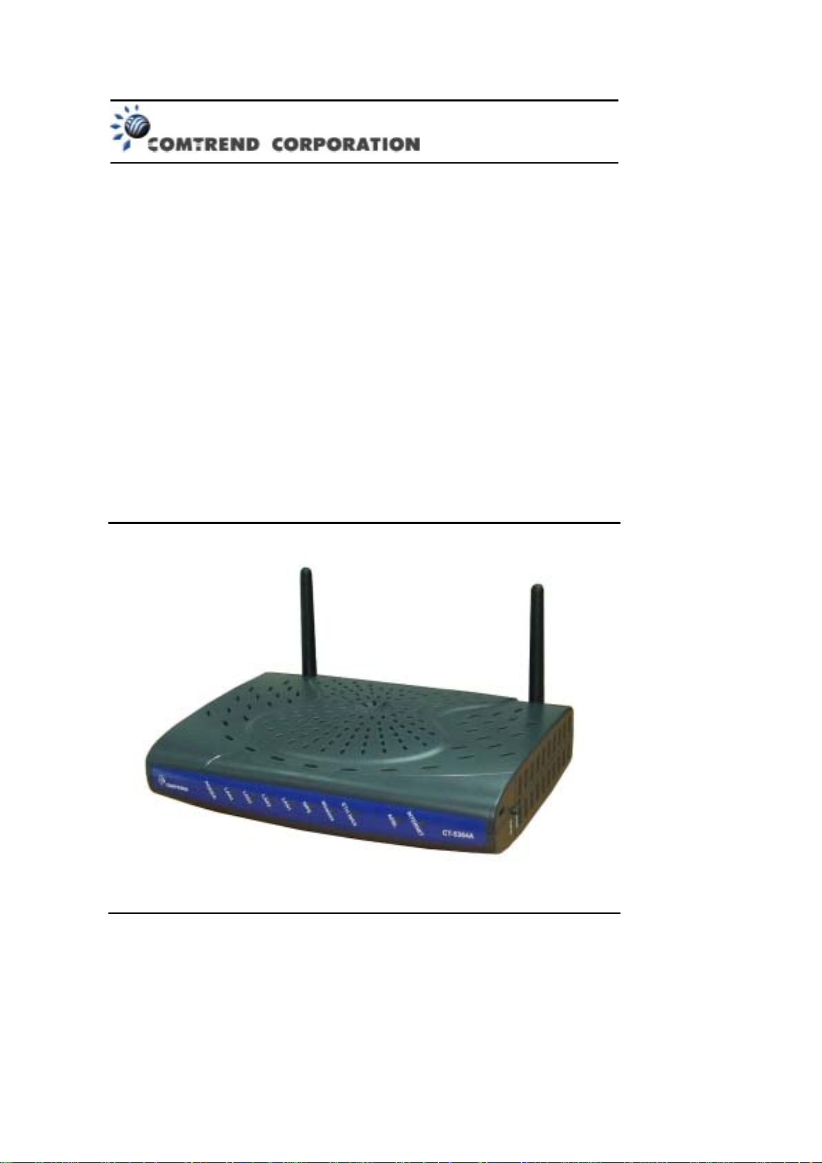
CT-5364A
802.11n ADSL2+ Router
User Manual
V e rsion A2.0, May 17, 2010
261091-007
Page 2

Preface
This manual provides information related to the installation and operation of this
device. The individual reading this manual is presumed to have a basic
understanding of telecommunications terminology and concepts.
If you find the product to be inoperable or malfunction ing, please conta ct techn ical
support for immediate service by email at INT-support@comtrend.com
For product update, new product release, manual revision, or software upgrades,
please visit our website at ht tp://www.comtrend.com
Important Safety Instructions
With reference to unpacking, installation, use, and maintenance of your electronic
device, the following basic guidelines are recommended:
• Do not use or install this product near w ater, to avoid fire or shock hazard. For
example, near a bathtub, kitchen sink or laundry tub , or near a s wimming pool.
Also, do not expose the equipment to rain or damp areas (e.g. a wet basement).
• Do not connect the power supply cord on elevated surfaces. Allow it to lie freely.
There should be no obstruct ions in its path and no heavy items shou ld be placed
on the cord. In addition, do not walk on, step on, or mistreat the cord.
• Use only the power cord and adapter that are shipped with this device.
• T o safeguard the equipment against overheating, make sure that all openings in
the unit that offer exposure to air are not b lock ed.
• Avoid using a telephone (other than a cordless type) during an electrical storm.
There may be a remote risk of electric shock from lightening. Also, do not use
the telephone to report a gas leak in the vicinity of the leak.
• Never install telephone wiri ng during storm y wea ther c onditions.
CAUTION:
To reduce the risk of fire, use only No. 26 AWG or larger
telecommunication l in e cord.
Always discon nect all te lephone line s from the w all outlet bef ore servi cing
or disassembling this eq uipm ent .
WARNING
Disconnect the power line from the device before servicing.
Power supply specifications are clearly stated in Appendix C.
1
Page 3

FCC Compliance
This device complie s w it h Part 15 of the F CC Ru le s. Op e ration is subject to the
following two conditions:(1) this devic e may not cause harmful interference, and (2)
this device must accept any interference received, including interference that may
cause undesired operation.
Notice: The changes or modifications not expressly approved by the party
responsible for compliance could void the user’s authority to operate the equipment.
IMPORTANT NOTE: To comply wit h the FCC RF expo sure compl iance req uirement s,
no change to the antenna or the device is permitted. Any change to the antenna or
the device could result in the device exceeding the RF exposure requirements and
void user’s authority to operate the device.
The Federal Communication Commission Radio Frequency Interference Statement
includes the following paragraph:
The equipment has been tested and found to comply with the limits for a Class
Digital Device, pursuant to part 15 of the FCC Rules. These limits are designed to
provide reasonable protection against harmful interference in a residential
installation. This equ ipment generates, uses and can rad iate radio frequency energy
and, if not insta lled and used i n accordan ce with the instructi on, may cause harmf ul
interference to radi o communication. However, ther e is no grantee that interference
will not occur in a particular installation. If this equipment dose cause harmful
interference to radio or tele vision receptio n, which can be dete rmined by turning the
equipment off and on, the user is encouraged to try to correct the interference by
one or more of the fol l owing mea su res:
--Reorient or relocate the receiving antenna.
--Increase the separation between the equipment and receiver.
--Connect the equipment into an outlet on a circuit diff erent from that to which t he
receiver is connected.
--Consult the dealer or an experienced radio/TV technician for help.
The user should not modify or change this equipment without written approval form
Comtrend Corporation .Modifi cat ion cou ld void a uthori t y to use this equipm ent.
IMPORTANT NOTE: To comp ly with the FC C RF exposure com pliance re qui rements,
the antenna(s) used for this transmitter mus t be installe d to provide a separation
distance of at least 20 cm from all persons and must not be co-located or operating
in conjunction with any other antenna or trans mitte r. No change to the antenna or
the device is permitted. Any change to the antenna or the device could result in the
device exceeding the RF exposure requirements and void user’s authority to operate
the device.
2
Page 4
Copyright
Copyright©2010 Comtrend Corporation. All rights reserved. The information
contained herein is proprietary to Comtrend Corporation. No part of this document
may be translated, transcribed, reproduced, in any form, or by any means without
prior written consent of Comtrend Corporation.
This program is free software: you can redistribute it and/or modify it under the
terms of the GNU General Public License as published by the Free Software
Foundation, either version 3 of the License, or (at your option) any later version.
This program is distributed in the hope that it will be useful, but WITHOUT ANY
WARRANTY; without even the implied warranty of MERCHANTAILITY or FITNESS
FOR A PARTICULAR PURPOSE. See the GNU General Public License for more
details.
You shou ld hav e rece iv ed a copy of the GNU Gene r al Public License along with this
program. If not, see http://www.gnu.org/licenses/
NOTE: This document is subject to change without notice.
Protect Our Environment
This symbol indicates that when the equipment has reached the end of
its useful life, it must be taken to a recycling centre and processed
separate from dome st ic w a ste .
The cardboard box, the plastic contained in the packaging, and the parts that make
up this router can b e recycle d in accordance w ith regionally e stablished re gulations.
Never dispose of this electronic equipment along with your household waste; you
may be subject to penalties or sanctions under the law. Instead, please be
responsible and ask for disposal instructions from your local government.
3
Page 5

Table of Contents
CHAPTER 1 INTRODUCTION..........................................................................................................6
1.1 F
EATURES
1.2 A
PPLICATION
CHAPTER 2 INSTALLATION............................................................................................................8
2.1 H
ARDWARE SETUP
2.2 LED I
CHAPTER 3 WEB USER INTERFACE...................... ......................................................................11
3.1 D
EFAULT SETTINGS
3.2 IP C
3.3 L
OGIN PROCEDURE
CHAPTER 4 QUICK SETUP............................................................................................................. 16
4.1 A
UTO QUICK SETUP
4.2 M
ANUAL QUICK SETUP
4.2.1PPP over ATM (PPPoA) and PPP over Ethernet (PPPoE)............................... ............ 20
4.2.2MAC Encapsulation Routing (MER)..............................................................................25
4.2.3IP Over ATM.................................................................................................................. 29
4.2.4Bridging.........................................................................................................................32
CHAPTER 5 DEVICE INF OR MAT ION.......................................................................................... 35
5.1 WAN............................................................................................................................................. 36
5.2 S
TATISTICS
5.2.1LAN Statistics .................................................................................................................37
5.2.2WAN Statistics................................................................................................................38
5.2.3ATM Statistics.......................................................................... ......................................39
5.2.4xDSL Statistics...............................................................................................................41
5.3 R
OUTE
5.4 ARP .............................................................................................................................................. 45
5.5 DHCP........................................................................................................................................... 45
CHAPTER 6 ADVANCED SETUP ....................................................................................................46
6.1 WAN............................................................................................................................................. 46
6.1.1VLAN Mux......................................................................................................................47
6.1.2MSP................................................................................................................................49
6.2 LAN.............................................................................................................................................52
6.3 NAT..............................................................................................................................................55
6.3.1Virtual Servers...... ..........................................................................................................55
6.3.2Port T rig geri ng........................... ...... .. ... ..... ... ... ..... .. ...... .. ... ..... ... ..... ... .. ...... .. ... ..... ... ..... .56
6.3.3DMZ Host....................................................................................................................... 57
6.3.4ALG................................................................................................................................ 58
6.4 S
ECURITY
6.4.1IP Filtering.....................................................................................................................59
6.4.2MAC Filtering................................................................................................................ 61
6.5 P
ARENTAL CONTROL
6.5.1Time of Day Restrictions................................................................................................62
6.5.2URL Filter...................... ................................................................................................64
6.6 Q
UALITY OF SERVICE (QO
6.6.1Queue Management Configuration................................................................................65
6.6.2Queue Configuratio n ........................................................................... ........................... 65
6.6.3QoS Classification.......................................................................................................... 67
6.7 R
OUTING
6.7.1Default Gateway............................................ ................................................................ 69
6.7.2Static Route....................................................................................................................70
6.7.3RIP................................................................................................................................. 71
6.8 DNS.............................................................................................................................................. 71
6.8.1DNS Server.....................................................................................................................71
6.8.2Dynamic DNS.................................................................................................................72
....................................................................................................................................... 6
................................................................................................................................... 7
..........................................................................................................................8
NDICATORS
ONFIGURATION
..........................................................................................................................................44
..........................................................................................................................10
........................................................................................................................11
.......................................................................................................................12
.......................................................................................................................14
......................................................................................................................17
................................................................................................................. 18
.................................................................................................................................... 37
...................................................................................................................................... 59
..................................................................................................................... 62
S)......................................................................................................... 65
....................................................................................................................................... 69
4
Page 6

6.9
DSL..............................................................................................................................................73
6.10 P
RINT SERVER
6.11 I
NTERFACE GROUPING
6.12 IP SEC.........................................................................................................................................77
6.13 C
ERTIFICATE
6.13.1Local..............................................................................................................................80
6.13.2Trusted CA ........................... ..........................................................................................82
CHAPTER 7 WIRELESS................................................................................................................... 83
7.1 B
ASIC
............................................................................................................................................83
7.2 S
ECURITY
7.2.1WPS................................................................................................................................87
7.3 MAC F
7.4 W
IRELESS BRIDGE
7.5 A
DVANCED
7.6 S
TATION INFO
CHAPTER 8 DIAGNOSTICS............................................................................................................ 98
8.1 D
IAGNOSTICS
CHAPTER 9 MANAGEMENT.......................................................................................................... 99
9.1 S
ETTINGS
9.1.1Backup Settings..............................................................................................................99
9.1.2Update Settings.............................................................................................................. 99
9.1.3Restore De fa ult............. ................................................................................................ 100
9.2 S
YSTEM LOG
9.3 SNMP A
9.4 TR-069 C
9.5 I
NTERNET TIME
9.6 A
CCESS CONTROL
9.6.1Services........................................................................................................................106
9.6.2IP Addre sse s................. .. ...... .. ..... ... ..... ... ... ..... .. ...... .. ...... .. ... ..... ... ..... ... ..... ... .. ..... ... ..... ..107
9.6.3Passwords ....................................................................................................................108
9.7 U
PDATE SOFTWARE
9.8 R
EBOOT
APPENDIX A - FIREWALL.............................................................................................................. 111
APPENDIX B - PIN ASSIGNMENTS..............................................................................................114
APPENDIX C - SPECIFICATIONS.................................................................................................115
APPENDIX D - SSH CLIENT...........................................................................................................117
APPENDIX E - PRINTER SERVER................................................................................................118
.............................................................................................................................74
................................................................................................................ 75
............................................................................................................................... 80
...................................................................................................................................... 85
ILTER
................................................................................................................................. 92
........................................................................................................................93
.................................................................................................................................... 94
................................................................................................................................96
................................................................................................................................98
...................................................................................................................................... 99
............................................................................................................................... 101
GENT
.............................................................................................................................103
LIENT
...........................................................................................................................103
...........................................................................................................................105
.......................................................................................................................106
.....................................................................................................................109
.......................................................................................................................................110
5
Page 7

Chapter 1 Introduction
The CT-5364A 802.11n ADSL2+ Router provides wired and wireless access for
high-bandwidth applications in the home or office. It includes one ADSL port and
five 10/100 ase-T Fast Ethernet ports, with one Ethernet port assigned to the
Ethernet WAN and the other four supporting LAN traffic. An added US host port
supports printers. The front and back panels are TR-068 compliant, with colored
panels and LED indicators that make for easy setup and use.
An integrated 802.11n (2x2 MIMO) WLAN Access Point supports faster c onnections
(up to 270Mbps) and increased range compared with 802.11b or 802.11g protocols,
without sacrific ing compatib ility with th ese older st andards. A WP S (Wi-Fi Protect ed
Setup) button is include d f or easy and secur e wir ele s s net work set up . Se cu r it y
features include 64/128 bit WEP and WPA/WPA2 encryption, firewall and VPN.
1.1 Features
• Printer Server throug h US host • 2x2 MIMO wireless antennas
• Ethernet WAN or ADSL access • 802.11b/g backward-compatible
• Auto PVC configu ration, up to 16 VCs • Wireless Distribution System (WDS)
• DHCP Client/Server/Relay • Wi-Fi Protected Setup (WPS)
• Dynamic IP assignment • Strong wireless secur i t y encr ypt i on
• Static and RIP v1/v2 rout ing • WPA/WPA2 and 802.1x
• DNS Proxy/Relay • Supports remote administration
• Per-VC packet level Q o S • TR-069/TR-098/TR-111 protocols
• IP/TCP/UDP Qo S • Configuration backup and restor ation
• NAT/PAT • Automatic firmware upgrade
• IP/MAC address filtering • FTP/TFTP server
• Parental Contro l • RADIUS client
• UPnP • Web-based management
• IGMP Proxy • Embedded SNMP agent
• WMM • TR-068 compliant color connectors
• Integrated 802.11n AP
6
Page 8
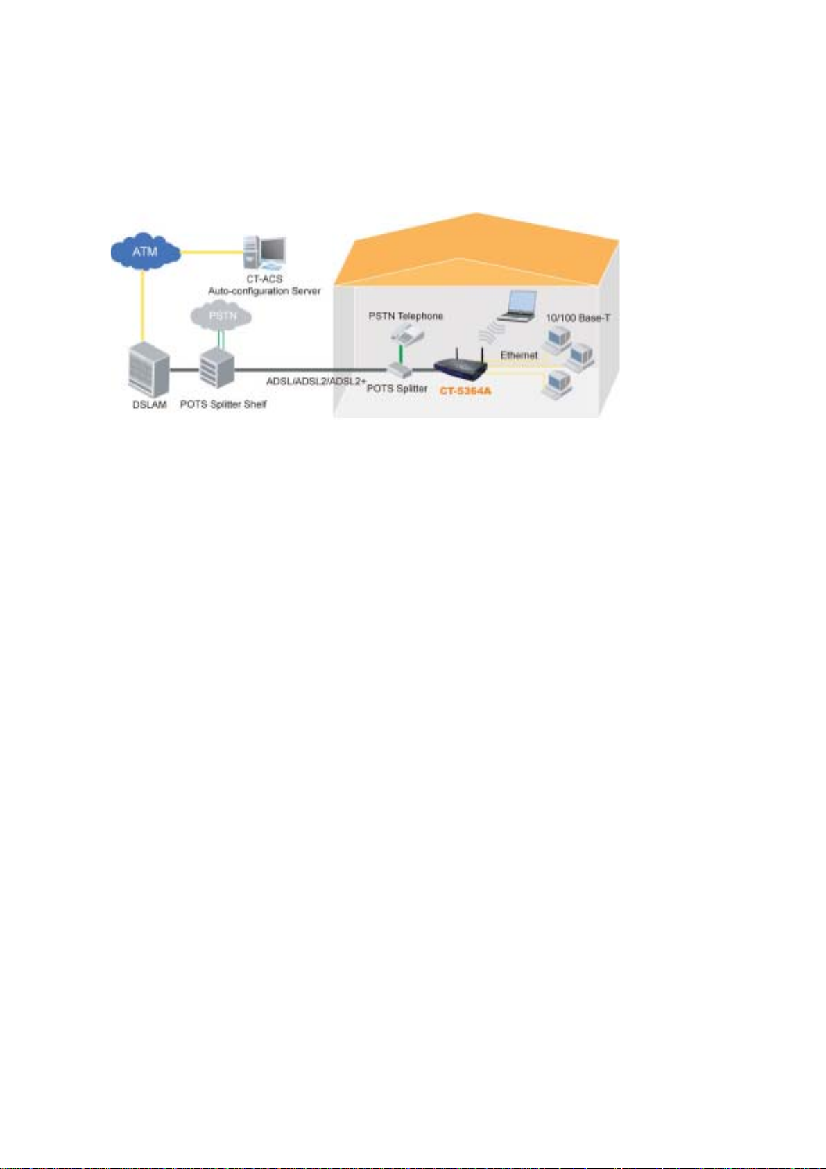
1.2 Application
The following diagram depicts the application of the CT-5364A.
7
Page 9

Chapter 2 Installation
2.1 Hardware Setup
Follow the instructions below to complete the hardware setup.
BACK PANEL
The figure below shows the back panel of the device.
ADSL PORT
Connect the ADSL line to the ADSL port with a RJ-11 (telephone) cable.
LAN PORTS
Use RJ-45 cable to connect up to four network devices. These ports are
auto-sensing MDI/X and either straight-through or crossover cable can be used.
ETH WAN PORT
Use RJ45 straight through or crossover MDI/X cable to connect to Ethernet WAN.
USB HOST PORT
The high-speed US2.0 host connection connects compatible US devices.
This firmware release supports most printers.
• Consult Appendix E for generic printer setup.
POWER ON
Press the power button to the OFF position (OUT). Connect the power adapter to
the power port. Attach the power adapter to a wall outlet or other AC source. Press
the power button to the ON position (IN). If the Power LED displays as expected
(see section 2.2 LED Indicators) then the CT-5364A is ready for use.
Caution 1: If the device fails to power up, or it malfunctions, first verify that the
power cords are connected securely and then power it on again. If the
problem persists, contact technical support.
Caution 2: efore servicing or disassembling this equipment, disconnect all power
cords and telephone lines from their outlets.
8
Page 10
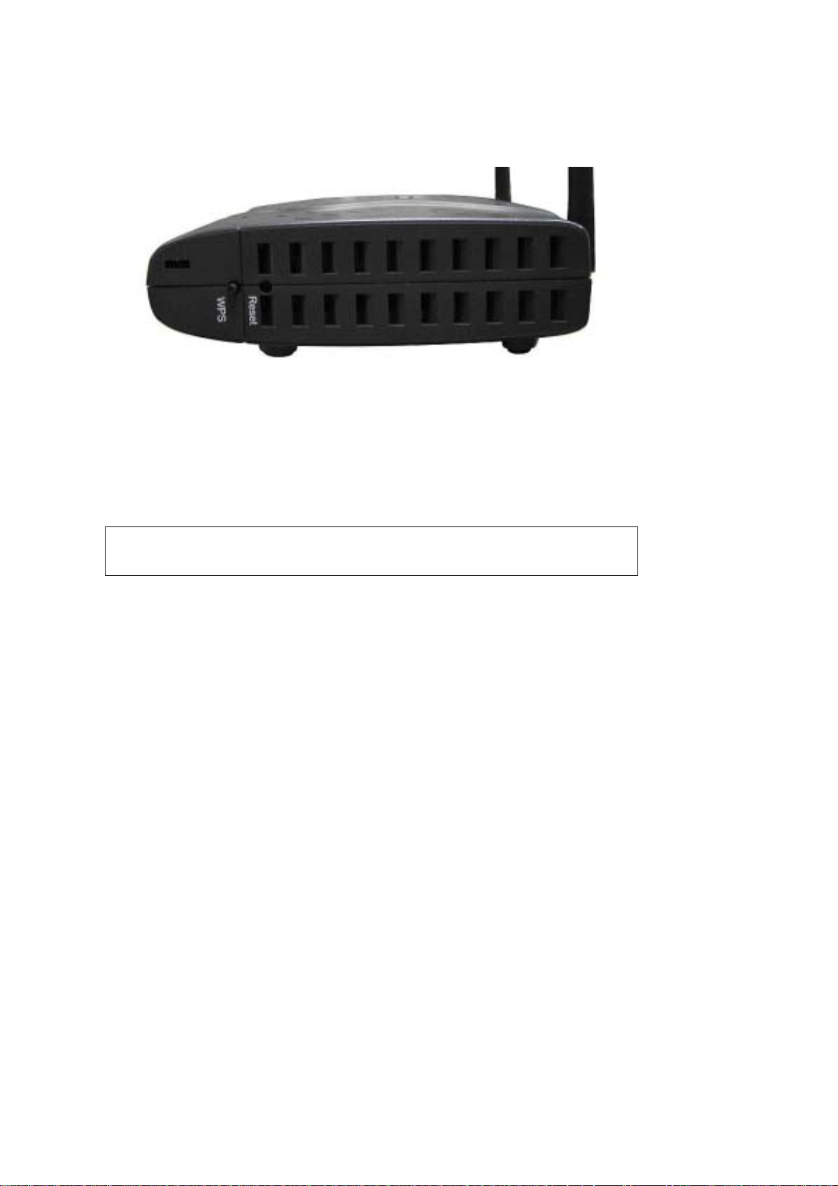
SIDE PANEL
The figure below shows the right-side panel of the device.
WPS BUTTON
Press this button t o begin sear ching f or WPS clie nts. These cl ients must a lso enabl e
WPS push button mode. When WPS is available the WPS LED will be ON.
Reset Button
Restore the default parameters of the device by pressing the Reset button for 5 to
10 seconds. After the device has rebooted successfully, the front panel should
display as expect ed (see section
2.2 LED Indicators for details).
NOTE: If pressed down for more than 20 seconds, the CT-5364A will go into a
firmware update state (CFE boot mode). The firmware can then be
updated using an Internet browser pointed to the default IP address.
9
Page 11

2.2 LED Indicators
g
The front panel LED indicators are shown below and explained in the following table.
This information can be used to chec k the stat us of the device and it s connec tion s.
LED Color Mode Function
Green
POWER
Red On
LAN 4X-1X Green
WPS Green
Wireless Green
ETH WAN Green
ADSL Green
Green
INTERNET
Red On
On The device is powered up.
Off The device is powered down.
POST (Power On Self Test) failure or other
malfunction. A malfunction is an y erro r of internal
sequence or state that will prevent the device from
connectin
On An Ethernet Link is established.
Off An Ethernet Link is not established.
link Data transmitting or receiving over LAN.
On WPS enabled.
Off WPS disenabled.
link The router is searching for WPS clients.
On The wireless module is ready.
(i.e. installe d and ena bled).
Off
link Data transmitting or receiving over WLAN.
On An Ethernet WAN Link is established.
Off An Ethernet WAN Link is not established.
link Data transmitting or receiving over Ethernet WAN.
On The ADSL link is established.
Off The ADSL link is not established.
link The ADSL link is training.
On IP connected and no traffic detected. If an IP or
Off Modem power off, modem in bridged mode or ADSL
link IP connected and IP T r affic is p assing thru the device
The wireless module is not ready .
(i.e. either not installed or di sabled).
PPPoE session is dropped due to an idle timeout, the
light will remain green if an ADSL connection is still
present.
connection not pr esent. In addition, if an IP or
PPPoE session is droppe d for any reason, other t han
an idle timeout, the light is turned off.
(either direction)
Device attempted to become IP connected and failed
(no DHCP response, no PPPoE resp ons e, PPPoE
authentication failed, no IP address from IPCP, etc.)
to the DSLAM or passing customer data.
10
Page 12

Chapter 3 Web User Interface
This section describes how to access the device via the web user interface (WUI)
using an Internet browser such as Internet Explorer (version 5.0 and later).
3.1 Default Settings
The factory default settings of this device are summarized below.
• LAN IP address: 192.168.1.1
• LAN subnet mask: 255.255.255.0
• Administrative access (username: root , password: 12345)
• User access (username: user, password: user)
• Remote WAN access:
• Remote (WAN) access (username: support, password: support)
• WLAN access: enabled
• Service Set Identifier (SSID): Comtrend_xxxx,
where xxxx are the last-four digits of the MAC address of the wireless interface.
Technical Note
During power on, the device initializes all settings to default values. It will then
read the configuration profile from the permanent storage section of flash memory.
The default attributes are overwritten when identical attributes with different values
are configured. The configuration profile in permanent storage can be created v ia
the web user interface or telnet user inter face, or other management protocols.
The factory default conf iguration can be rest ored either by push ing the reset button
for more than f ive seco nds unt il the po wer in dica te s LED bli nking or by c lick ing th e
Restore Default Configuration option in the Restore Settings screen.
enabled
11
Page 13
3.2 IP Configuration
DHCP MODE
When the CT-5364A powers up, the onboard DHCP server will switch on.
The DHCP server iss ues and reserves I P addresses for LAN d evices, such as yo ur PC.
To obtain an IP address from the DCHP server, follow the steps provided below.
NOTE: The following procedure assumes you are running Windows XP.
However, the general steps involved are similar for most operating
systems (OS). C heck your O S supp ort do cumenta tion fo r f urthe r de ta ils .
STEP 1: From the Network Connections window, open Local Area Connection ( You
may also access this scr een by double-click ing the Local Area Connection
icon on your taskbar). Click the Properties button.
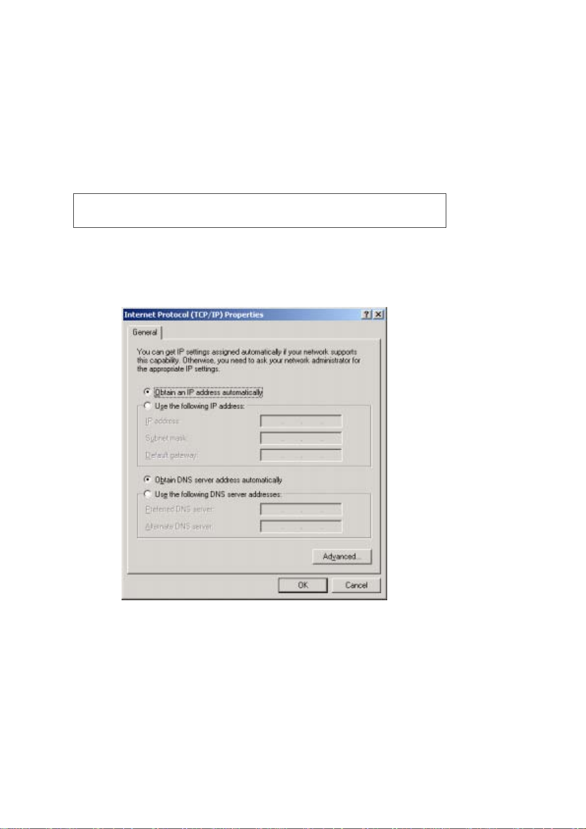
STEP 2: Select Internet Protocol (TCP/IP) and click the Properties button.
STEP 3: Select Obt ain an IP address automa ticall y as shown below.
STEP 4: Click OK to submit these settings.
If you experience difficulty with DHCP mode, you can try static IP mode instead, as
described on the next page.
12
Page 14
STATIC IP MODE
In static IP mode, you assign IP settings to your PC manually.
Follow these steps to configure your PC IP address to use subnet 192.168.1.x.
NOTE: The following procedure assumes you are running Windows XP.
However, the general steps involved are similar for most operating
systems (OS). C heck your O S supp ort do cumenta tion fo r f urthe r de ta ils .
STEP 1: From the Network Connections window , open Local Area Connection (You
may also access this scr een by double-click ing the Local Area Connection
icon on your taskbar). Click the Properties button.
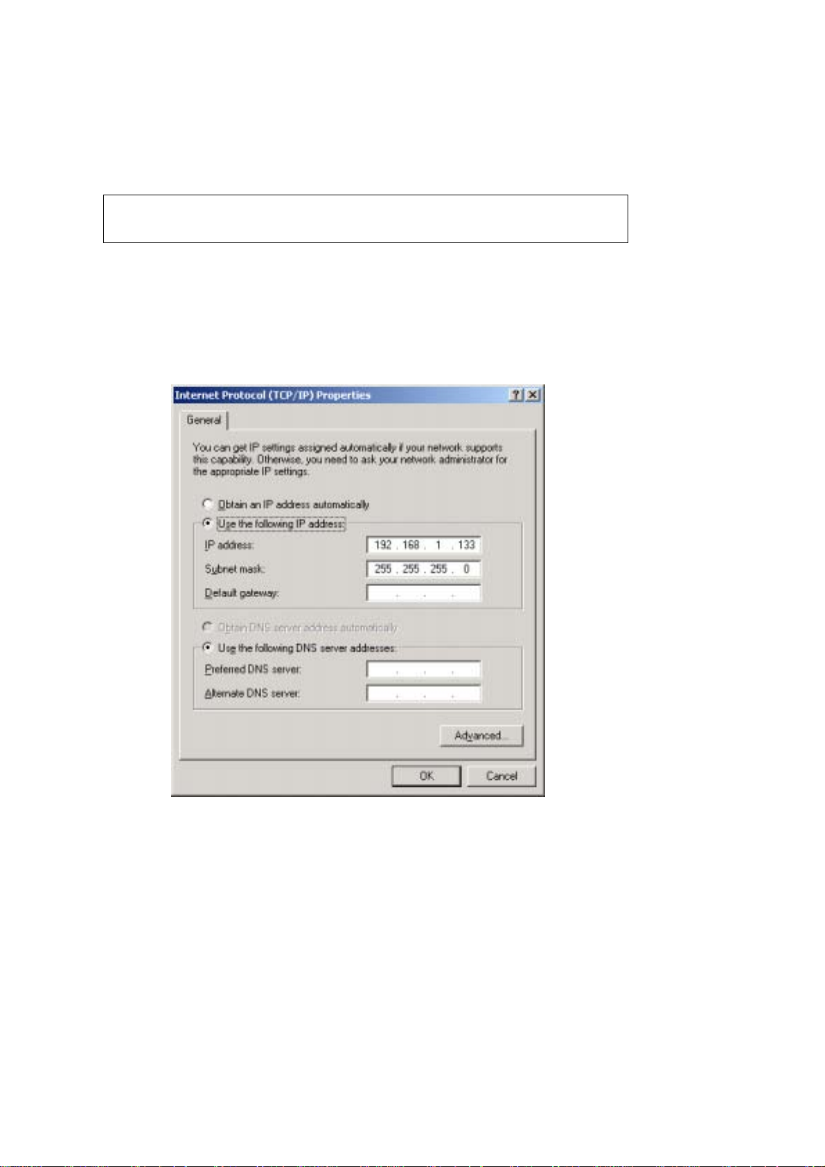
STEP 2: Select Internet Protocol (TCP/IP) and click the Properties button.
STEP 3: Change the IP address to the domain of 192.168.1.x (1<x<255) with
subnet mask of 255.255.255.0. The screen should now displa y as below.
STEP 4: Click OK to submit these settings.
13
Page 15
3.3 Login Procedure
Perform the following steps to login to the web user interface.
NOTE: The default settings can be found in section 3.1.
STEP 1: Start the Internet browser and enter the default IP address for the device
in the Web address field. For example, if the default IP address is
192.168.1.1, type http://192.168.1.1.
NOTE: For local ad m in istration (i.e. LAN access), the PC running the bro w ser
must be attached to the Ethernet, and not necessarily to the device. For
remote access (i.e. WAN), use the IP address shown on the Quick Setup
After login, the Quick Setup screen will appear as shown.
NOTE: The selections a vailable on the main menu are based upo n the configured
connection type and user account privileges.
The Quick Setup screen allows the user to configure the CT-5364A for ADSL
connectivity and Internet access. It also guides the user though the WAN network
setup first and then the LAN interface setup. You can either do this manually or
follow the auto quick setup (i.e. DSL Auto-connect) instructions.
This router supports the fol low in g data enca psu l at ion methods.
• PPP over Ethernet (PPPoE)
• PPP over A TM ( P PPoA)
• MAC Encapsulated Routing (MER)
• IP over ATM (IPoA)
• ridging
14
Page 16
The following configuration considerations apply:
• The WAN network operating mode operation depends on the service provider’s
configuration in the Central Office and roadband Access Server for the PVC
• If the service provider provides PPPoE service, then the connection selection
depends on whether the LAN-side device (typically a PC) is running a PPPoE
client or whether the router is to run the PPPoE client. The router can support
both cases simulta ne ously.
• If none of the LAN-side devices run PPPoE clients, then select PPPoE.
• NAT and firewall can be enabled or disabled by the user in router modes (PPPoE,
PPPoA, MER or IPoA) and they are always disabled with ridge mode.
• Depending on the network operating mode, and whether NAT and firewall are
enabled or disabled, the main menu will display or hide NAT and Firewall.
NOTE: Up to sixteen PVC profiles can be configured and saved on the flash
memory. To activate a particular PVC profile, you need to navigate all the
Quick Setup pages until the last summary page, then click on the Finish
button and reboot the system.
3.4 Auto Quick Setup
The auto quick setup requires the ADSL link to be up. The ADSL router will
automatically detect the PVC, so just follow the easy online instructions.
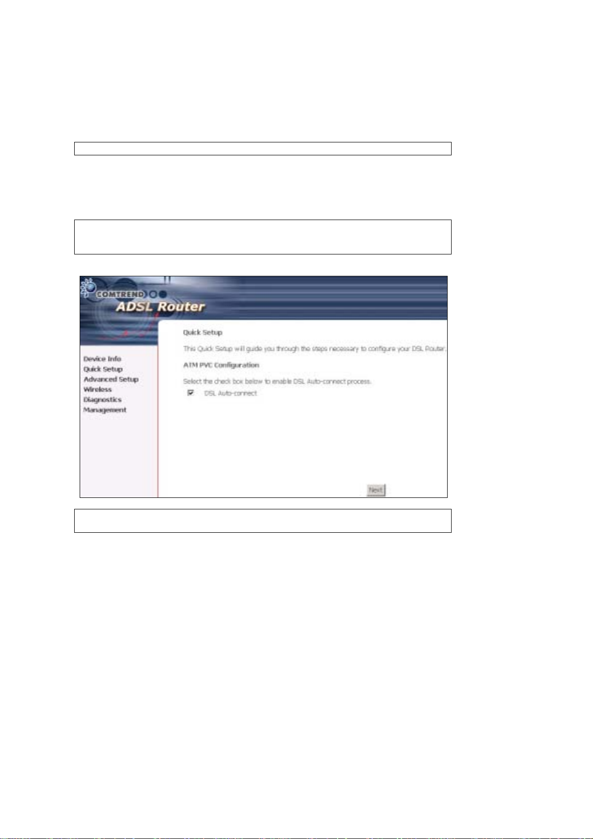
STEP 1: Select Quick Setup to display this screen.
STEP 2: Click Next to sta rt t h e set up pro ce s s. Follow the online instructions to
complete the settings. This procedure will skip some processes such as
the PVC index and encapsulation mode selection.
STEP 3: After the settings are complete, you can use the ADSL service.
15
Page 17
3.5 Manual Quick Setup
STEP 1: Click Quick Setup and un-tick the DSL Auto-connect checkbox to
enable manual configura t ion of the connect ion typ e.
STEP 2: Enter the Virtual Path Identifier (VPI) an d Virtual Channel Iden tifier (VCI)
values. Select Enable Qualit y Of Serv ice if required and click Next.
16
Page 18
STEP 3: Choose an Encapsulatio n mo de .
Choosing different connection types provides different encapsulation modes.
• PPPoA- VC /M U X, LLC/ENCAPSULATION
• PPPoE- LLC/SNAP RIDGING, VC/MUX
• MER- LLC/SNAP-RIDGING, VC/MUX
• IPoA- LLC/SNAP-ROUTING, VC MUX
• ridging- LLC/SNAP-RIDGING, VC/MUX
NOTE: Subsections 4.2.1 - 4.2.4 describe the PVC setup procedure further.
Choosing different connection types pops up different settings requests.
Enter settings as directed by your Internet Service Provider (ISP).
17
Page 19
3.5.1 PPP over ATM (PPPoA) and
PPP over Ethernet (PPPoE)
STEP 4: Select the PPP over ATM (PPPoA) or PPP over Ethernet (PPPoE) radio
button and click Next. The following screen appears.
PPP Username/PPP Password: The PPP Username and the PPP password
requirement are dependent on the particular requirements of the ISP or the ADSL
service provider. The WE user interface allows a maximum of 256 characters for
the PPP user name and a maximum of 32 characters for the PPP password.
PPPoE Service Name: For PPPoE service, PADI requests contain a service label.
Some PPPoE servers (or RAS) of ISP chec k this service labe l to make a connection.
Dial on Demand
The device can be configured to disco nnect if there is no act ivity for a period of time
by selecting this che ck bo x. When the checkbox is ticked, you must enter th e
inactivity timeout period. The timeout period ranges from 1 to 4320 minutes.
18
Page 20

PPP IP Extension
The PPP IP Extension is a special feature deployed by some service providers.
Unless your service provider specially requires this setup, do not select it.
PPP IP Extension does the following:
• Allows only one PC on the LAN
• The public IP address assigned by the remote side using the PPP/IPCP
protocol is actually not used on the WAN PPP interface. Instead, it is
forwarded to the PC LAN interface through DHCP. Only one PC on the
LAN can be connected to the remote, since the DHCP server within the
device has only a single I P address to assign to a LAN device.
• The device becomes the default gateway and DNS server to the PC
through DHCP using the LAN interface IP address.
• The device extends the IP subnet at the remote service provider to the
LAN PC. i.e. the PC becomes a host belonging to the same IP subnet.
• The device bridges the IP packets between WAN and LAN ports, unless
the packet is addressed to the device’s LAN IP address.
Enable NAT
If the LAN is configured with a private IP address, the user should select this
checkbox. The NAT submenu will display after the next reboot. The user can then
configure NAT -related features. If a private IP address is not used on the LAN side,
this checkbox should not be selected so as to free up system resources.
Enable Fullcone NAT: Known as one-to-one NAT, all requests from the same
internal IP address and port are mapped to the same external IP address and port.
An external host can se nd a p acket to t he int erna l h ost, b y send ing a p acket to th e
mapped external address.
Enable Firewall
If the firewal l checkbo x is select ed, the Security sub menu wil l displa y after the ne xt
reboot. The user can then configure firewall features. If the firewall is not used,
this checkbox should not be selected so as to free up system resources.
Use Static IP Address
Unless your service provid er specially requires this setup, do not select it.
If selected, enter your static IP address.
Retry PPP password on authentication error
Tick the box to select.
Enable PPP Debug Mode
Enable the PPPoE debug mode. The system will put more PPP connection
information in System Log. This is used for debugging purposes.
Bridge PPPoE Frames Between WAN and Local Ports
If Enabled, the function can create a local PPPoE connection to the WAN side.
Fixed MTU
Select the checkbox to enable Fixed MTU and adjust the MTU value for WAN
Interface, PPPoE and PPPoA. Default values are 1492 for PPPoE and 1500 for
PPPoA.
19
Page 21
STEP 5: Click Next to display the following screen.
Enable IGMP Multicast: Tick the checkbox to enable IGMP multicast (proxy).
IGMP (Internet Group Membership Protocol) is a protocol used by IP hosts to report
their multicast group memberships to any immediately neighboring multicast
routers.
Enable WAN Service:
Tick this item to enable the ATM service. Untick it to stop the ATM service.
Service Name: This is a user defined label.
STEP 6: Af ter ente r ing y our settings, se lect Next. The following screen appears.
20
Page 22

The Device Setup screen allows the user to configure the LAN interface IP address,
subnet mask, and DHCP server. T o enable DHCP, select Enable DHCP server and
enter starting and ending IP addresses and the leased time
Since the router occupies the first two IP addresses (192.168.1.1 and 192.168.1.2),
the default private address range provided by the ISP server in the router is
192.168.1.3 through 192.168.1.254.
If NAT is disabled, Enable DHCP Server Relay will be displayed as an option. T o
enable it, se lect th e Enable DHCP Server Relay radio button and enter the DHCP
Server IP Address. This allows the router to relay the DHCP packets from the remote
DHCP server. The remote DHCP server will provide the IP address.
To config ure a s econdary IP address for the LAN port, click the checkbox shown.
STEP 7: Click Next to continue. To enable the wireless function, select the radio
button (as shown) and input a new SSID (if desired).
21
Page 23
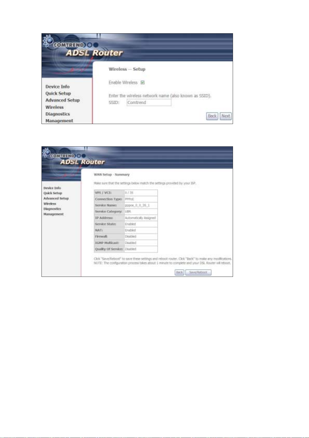
Click Next to display the fina l setup sc reen.
Step 9: The WAN Setup-Summary screen presents the proposed configuration.
Click Back to modify these settings . To apply these settings, click
Save/Reboot. The router will save the c onfiguration and reboot. After
the router reboots, the Web UI will refresh to the Device Info screen.
22
Page 24
3.5.2 MAC Encapsulation Routing
(MER)
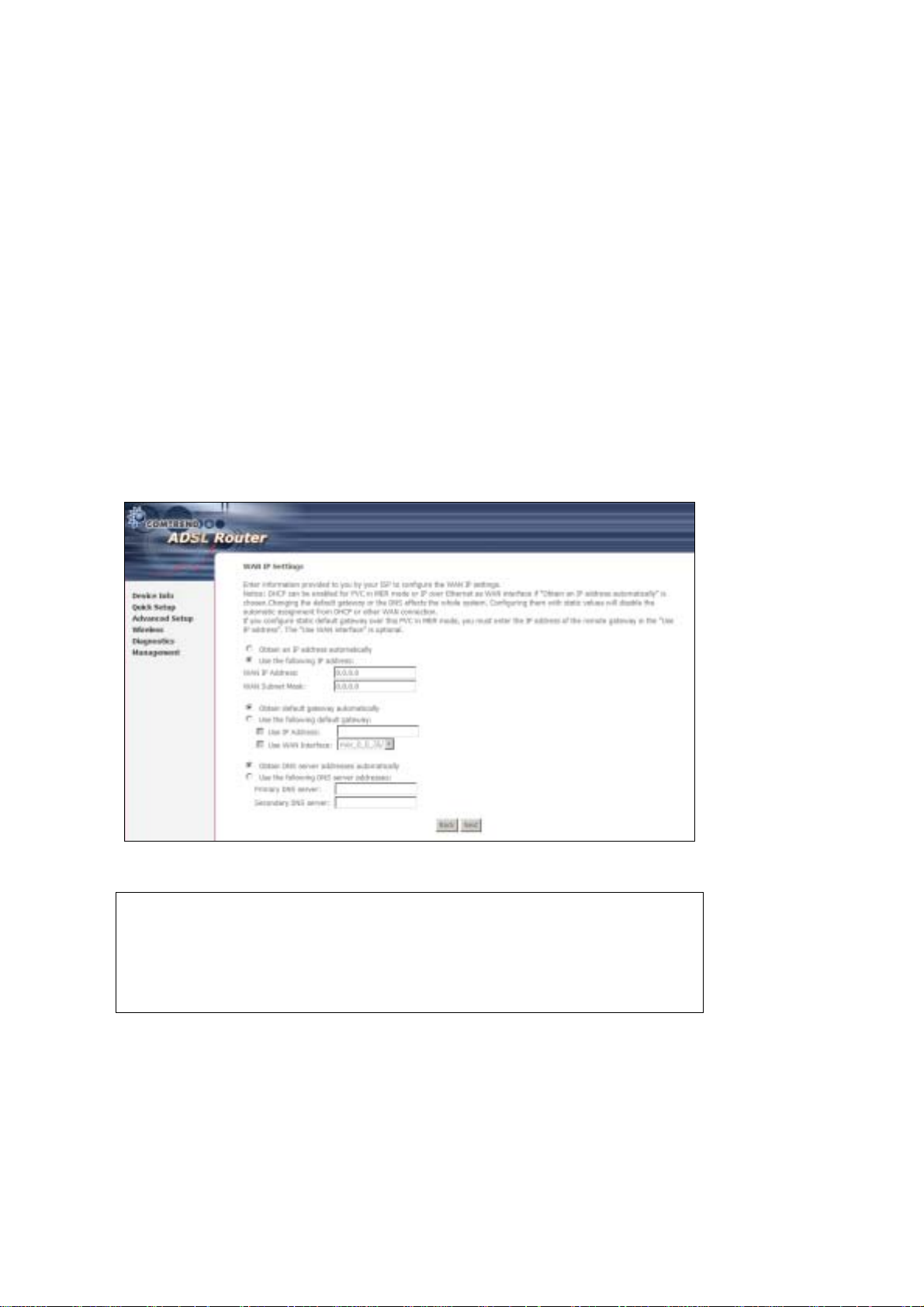
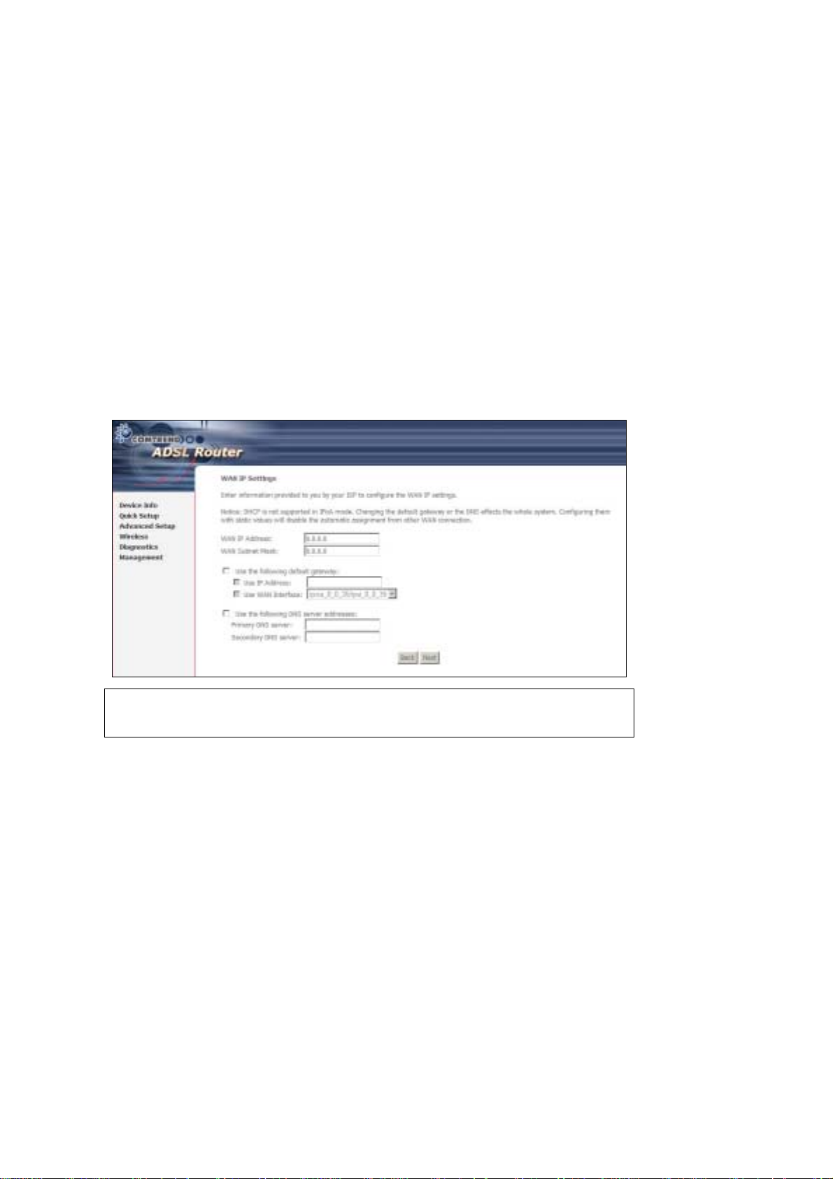
Step 4: Select the MAC Encapsulat ion Rout ing (MER) radi o button and clic k Next.
Enter information provided to you by your ISP to configure the WAN IP settings.
NOTE: DHCP can be enabled for PVC in MER mode if Obtain an IP address
automatically is chosen. Changi ng the default gateway or the DNS
affects the whol e system. Configur ing them with stat ic va lues wi ll disab le
the automatic assignment from DHCP or other WAN connection.
If you configure static default gateway over this PVC in MER mode, you
must enter the IP address of the remote gateway in the “Use IP address”
field. Your ISP should provide the values to be entered in these fields.
Step 5: Click Next to display the following screen.
23
Page 25

Enable NAT
If the LAN is configured with a private IP address, the user should select this
checkbox. The NA T submenu will disp lay after the ne xt reboot. The user can then
configure NA T- related features. If a private IP address is not used on the LAN side,
this checkbox should not be selected so as to free up system resources.
Enable Fullcone NAT: This option becomes available when NAT is enabled
Known as one-to-one NAT, all requests from the same internal IP address and port
are mapped to the sam e e xterna l I P addre ss an d port . An e xterna l h ost ca n send a
packet to the internal host, by sending a packet to the mapped external address.
Enable Firewall
If the firewal l checkbo x is select ed, the Se curity submenu wil l display a fter the nex t
reboot. The user can then configure firewall features. If the firewall is not used,
this checkbox should not be selected so as to free up system resources.
Enable IGMP Multicast: Tick the checkbox to enable IGMP multicast (proxy).
IGMP (Internet Group Membership Protocol) is a protocol used by IP hosts to report
their multicast group memberships to any immediately neighboring multicast
routers.
Enable WAN Service:
Tick this item to enable the ATM service. Untick it to stop the ATM service.
Service Name: This is a user defined label.
Step 6: Click Next to display the following screen.
24
Page 26
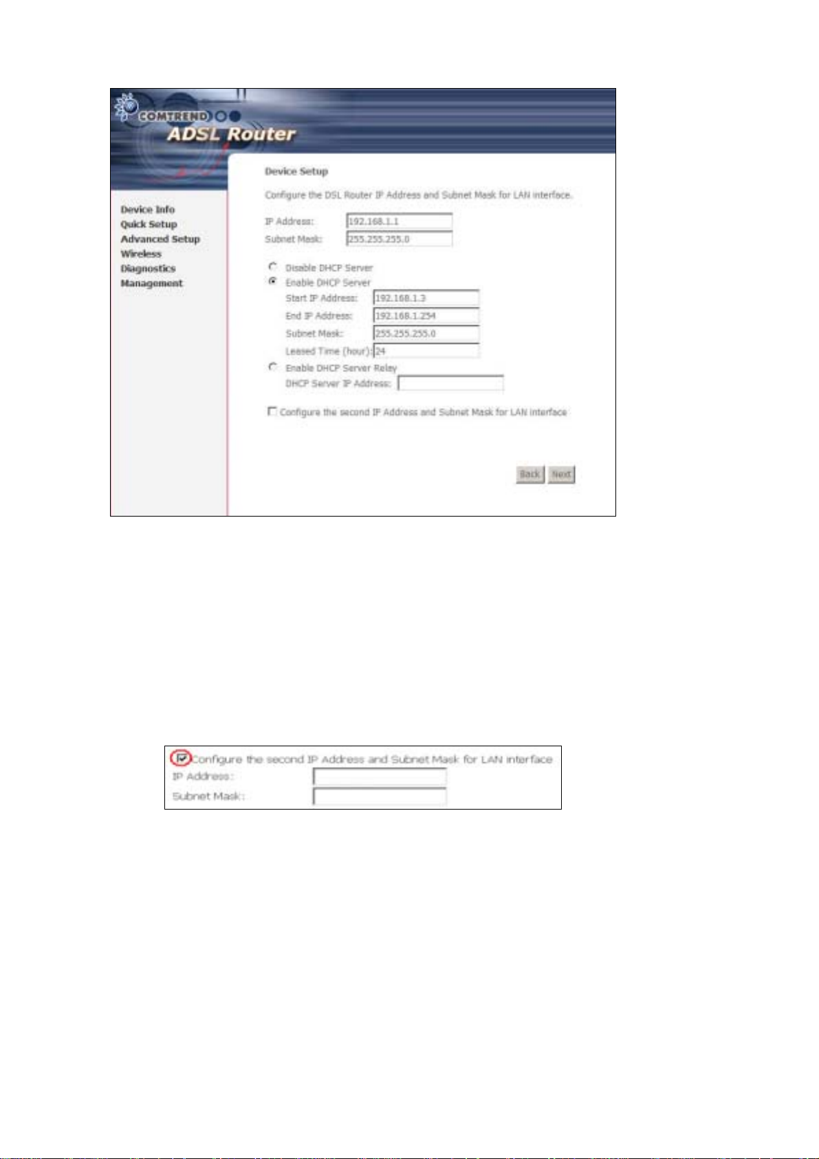
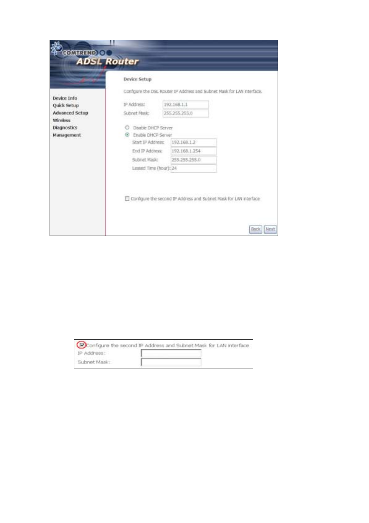
The Device Setup screen allows the user to configure the LAN interface IP address,
subnet mask, and DHCP server. T o enable DHCP, select Enable DHCP server and
enter starting and ending IP addresses and the leased time.
Since the router occupies the first two IP addresses (192.168.1.1 and 192.168.1.2),
the default private address range provided by the ISP server in the router is
192.168.1.3 through 192.168.1.254.
If NAT is disabled, Enable DHCP Server Relay will be displayed as an option. T o
enable it, se lect th e Enable DHCP Server Relay radio button and enter the DHCP
Server IP Address. This allows the router to relay the DHCP packets from the remote
DHCP server. The remote DHCP server will provide the IP address.
To config ure a s econdary IP address for the LAN port, click the checkbox shown.
Step 7: Click Next to continue. To enable the wireless function, select the radio
button (as shown) and input a new SSID (if desired).
25
Page 27
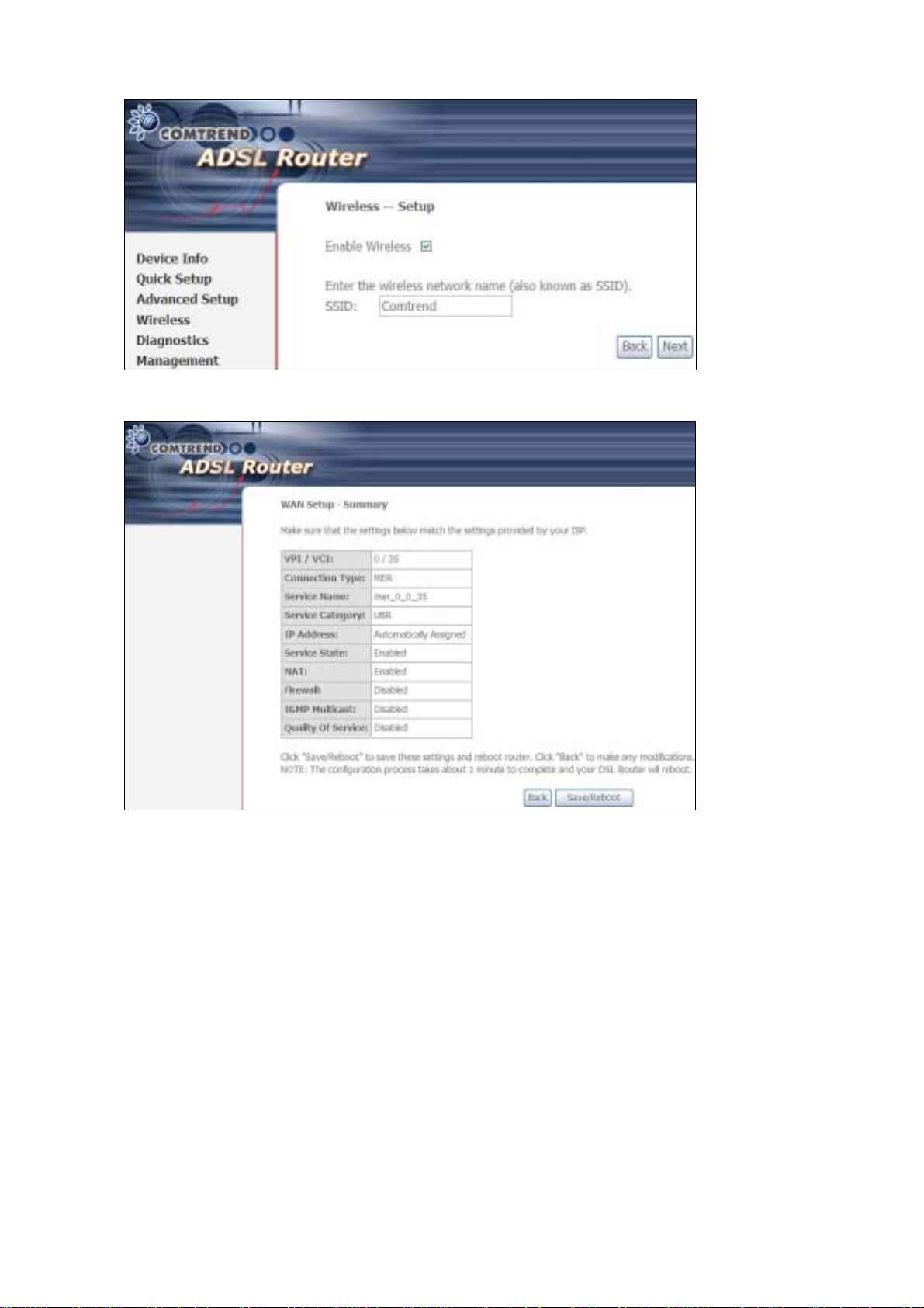
Click Next to display the fina l setup sc reen.
Step 8: The WAN Setup-Summary screen presents the proposed configuration.
Click Back to modify these settings . To apply these settings, click
Save/Reboot. The router will save the c onfiguration and reboot. After
the router reboots, the Web UI will refresh to the Device Info screen.
26
Page 28
3.5.3 IP Over ATM
Step 4: Select the IP over ATM (IPoA) radio button and click Next.
NOTE: DHCP is not supported over IPoA. The user must enter the IP address or
WAN interface for the default gateway setup and the DNS server
addresses provided by their ISP.
Step 5: Click Next to display the following screen.
27
Page 29

Enable NAT
If the LAN is configured with a private IP address, the user should select this
checkbox. The NAT submenu will display after the next reboot. The user can then
configure NA T- related features. If a private IP address is not used on the LAN side,
this checkbox should not be selected so as to free up system resources.
Enable Fullcone NAT: This option becomes available when NAT is enabled
Known as one-to-one NAT, all requests from the same internal IP address and port
are mapped to the sam e e xterna l I P addre ss an d port . An exte rnal h ost ca n send a
packet to the internal host, by sending a packet to the mapped external address.
Enable Firewall
If the firewal l checkbo x is select ed, the Security sub menu wil l displa y after the ne xt
reboot. The user can then configure firewall features. If the firewall is not used,
this checkbox should not be selected so as to free up system resources.
Enable IGMP Multicast: Tick the checkbox to enable IGMP multicast (proxy).
IGMP (Internet Group Membership Protocol) is a protocol used by IP hosts to report
their multicast group memberships to any immediately neighboring multicast
routers.
Enable WAN Service:
Tick this item to enable the ATM service. Untick it to stop the ATM service.
Service Name: This is a user defined label.
Step 6: Click Next to display the following screen.
28
Page 30
The Device Setup screen allows the user to configure the LAN interface IP address,
subnet mask, and DHCP server. T o enable DHCP, select Enable DHCP server and
enter starting and ending IP addresses and the leased time.
Since the router occupies the first two IP addresses (192.168.1.1 and 192.168.1.2),
the default private address range provided by the ISP server in the router is
192.168.1.3 through 192.168.1.254.
If NAT is disabled, Enable DHCP Server Relay will be displayed as an option. T o
enable it, se lect th e Enable DHCP Server Relay radio button and enter the DHCP
Server IP Address. This allows the router to relay the DHCP packets from the remote
DHCP server. The remote DHCP server will provide the IP address.
To config ure a s econdary IP address for the LAN port, click the checkbox shown.
STEP 7: Click Next to continue. To enable the wireless function, select the radio
button (as shown) and input a new SSID (if desired).
29
Page 31

Click Next to display the fina l setup sc reen.
Step 8: The WAN Setup-Summary screen presents the proposed configuration.
Click Back to modify these settings . To apply these settings, click
Save/Reboot. The router will save the c onfiguration and reboot. After
the router reboots, the Web UI will refresh to the Device Info screen.
3.5.4 Bridging
Step 4: Select the ridging radio button and click Next. The followi ng s creen
appears. Select Enable Bridge Service and click Next.
30
Page 32

Step 5: On this screen, you can change the LAN IP address of the router.
NOTE: In bridge mode, the router is not associated with a WAN IP address. This
means that it can only be managed from a PC on the LAN. For remote
management, you must select a routing type (PPPoE/A, MER, or IPoA).
31
Page 33

STEP 6: Click Next to continue. To enable the wireless function, select the radio
button (as shown) and input a new SSID (if desired).
Click Next to display the fina l setup sc reen.
Step 7: The WAN Setup-Summary screen presents the proposed configuration.
Click Back to modify these settings . To apply these settings, click
Save/Reboot. The router will save the c onfiguration and reboot. After
the router reboots, the Web UI will refresh to the Device Info screen.
Device Information screen and login with remote username and password.
STEP 2: A dialog box will appear, such as the one below. En ter the default
32
Page 34

username and password, as defined in section 3.1 Default Settings.
Click OK to continue.
NOTE: The login password can be changed later (see section 0).
33
Page 35

STEP 3: After successfully logging in for the first time, you will reach this screen.
34
Page 36

Chapter 4 Quick Setup
After login, the Quick Setup screen will appear as shown.
NOTE: The selections a vailable on the main menu are based upo n the configured
connection type and user account privileges.
The Quick Setup screen allows the user to configure the CT-5364A for ADSL
connectivity and Internet access. It also guides the user though the WAN network
setup first and then the LAN interface setup. You can either do this manually or
follow the auto quick setup (i.e. DSL Auto-connect) instructions.
This router supports the fol low in g data enca psu l at ion methods.
• PPP over Ethernet (PPPoE)
• PPP over A TM ( P PPoA)
• MAC Encapsulated Routing (MER)
• IP over ATM (IPoA)
• ridging
The following configuration considerations apply:
• The WAN network operating mode operation depends on the service provider’s
configuration in the Central Office and roadband Access Server for the PVC
• If the service provider provides PPPoE service, then the connection selection
depends on whether the LAN-side device (typically a PC) is running a PPPoE
client or whether the router is to run the PPPoE client. The router can support
both cases simulta ne ously.
• If none of the LAN-side devices run PPPoE clients, then select PPPoE.
• NAT and firewall can be enabled or disabled by the user in router modes (PPPoE,
PPPoA, MER or IPoA) and they are always disabled with ridge mode.
• Depending on the network operating mode, and whether NAT and firewall are
enabled or disabled, the main menu will display or hide NAT and Firewall.
35
Page 37

NOTE: Up to sixteen PVC profiles can be configured and saved on the flash
memory. To activate a particular PVC profile, you need to navigate all the
Quick Setup pages until the last summary page, then click on the Finish
button and reboot the system.
4.1 Auto Quick Setup
The auto quick setup requires the ADSL link to be up. The ADSL router will
automatically detect the PVC, so just follow the easy online instructions.
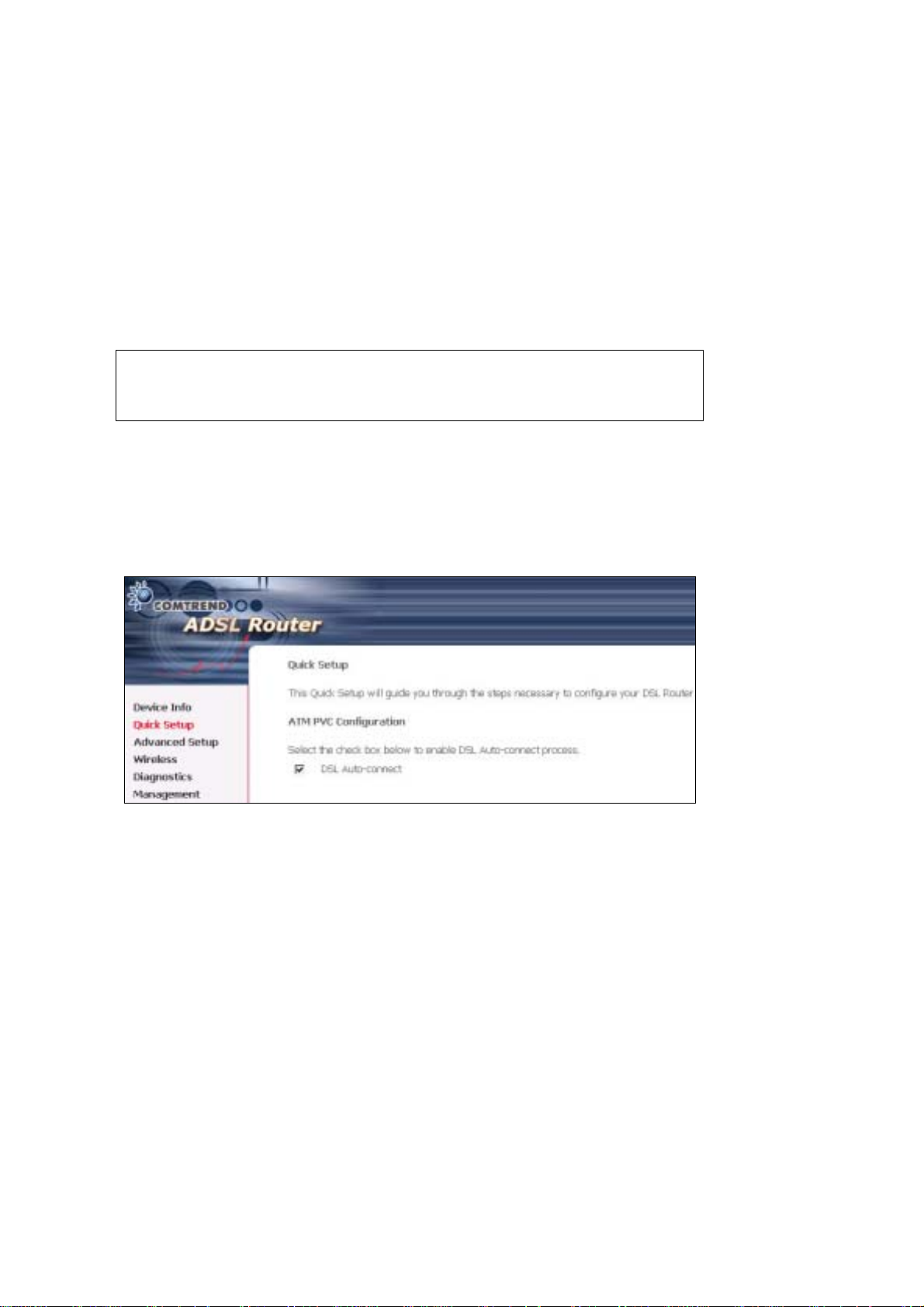
STEP 1: Select Quick Setup to display this screen.
STEP 2: Click Next to sta rt t h e set up pro ce s s. Follow the online instructions to
complete the settings. This procedure will skip some processes such as
the PVC index and encapsulation mode selection.
STEP 3: After the settings are complete, you can use the ADSL service.
36
Page 38

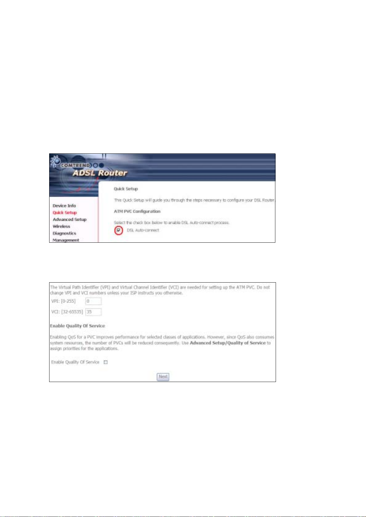
4.2 Manual Quick Setup
STEP 1: Click Quick Setup and un-tick the DSL Auto-connect checkbox to
enable manual configura t ion of the connect ion typ e.
STEP 2: Enter the Virtual Path Identifier (VPI) an d Virtual Channel Iden tifier (VCI)
values. Select Enable Qualit y Of Serv ice if required and click Next.
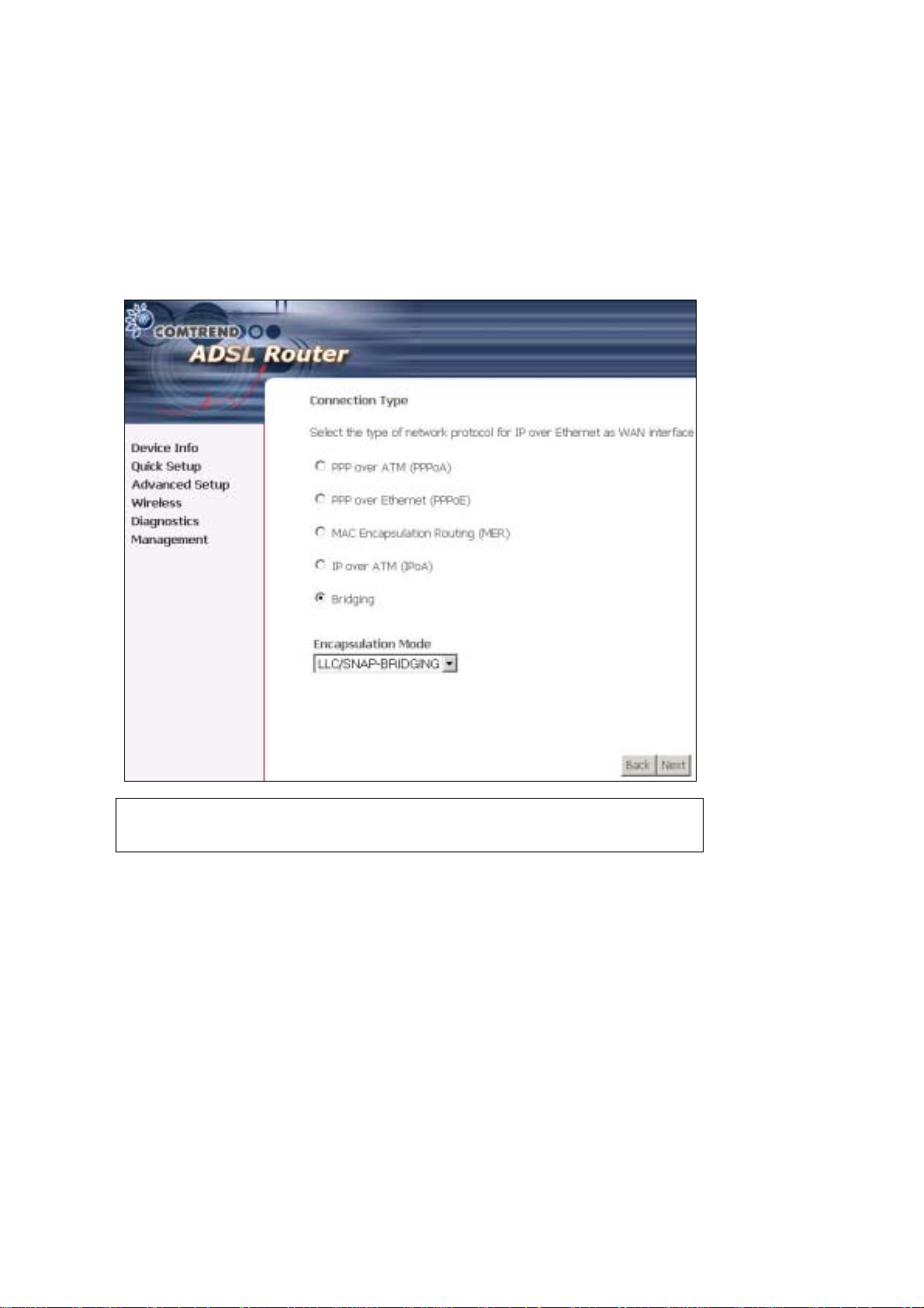
STEP 3: Choose an Encapsulatio n mo de .
Choosing different connection types provides different encapsulation modes.
• PPPoA- VC /M U X, LLC/ENCAPSULATION
• PPPoE- LLC/SNAP RIDGING, VC/MUX
• MER- LLC/SNAP-RIDGING, VC/MUX
• IPoA- LLC/SNAP-ROUTING, VC MUX
• ridging- LLC/SNAP-RIDGING, VC/MUX
Untick this checkbox to enable manual
setup and display the following screen.
37
Page 39

NOTE: Subsections 4.2.1 - 4.2.4 describe the PVC setup procedure further.
Choosing different connection types pops up different settings requests.
Enter settings as directed by your Internet Service Provider (ISP).
38
Page 40

4.2.1 PPP over ATM (PPPoA) and
PPP over Ethernet (PPPoE)
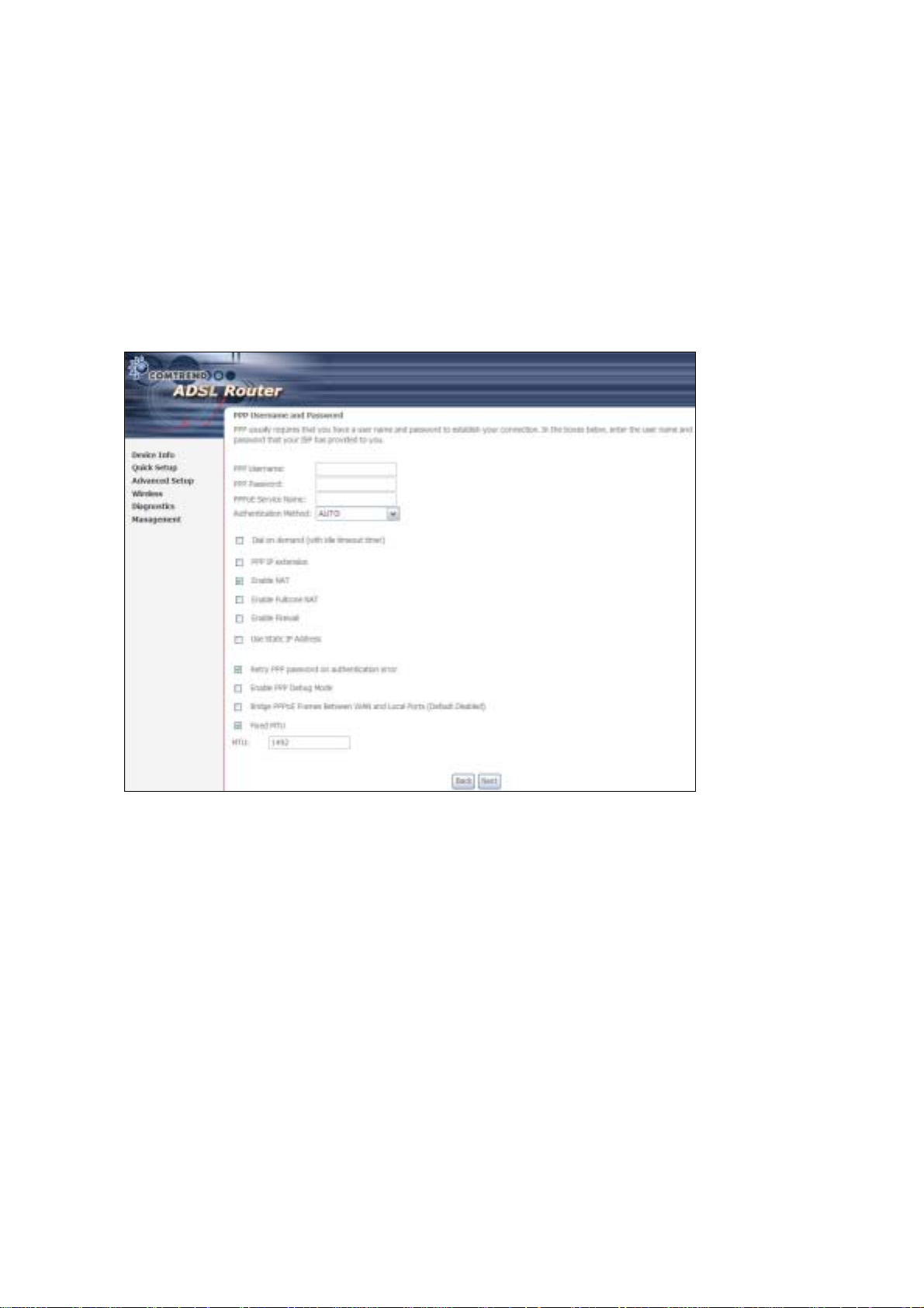
STEP 4: Select the PPP over ATM (PPPoA) or PPP over Ethernet (PPPoE) radio
button and click Next. The following screen appears.
PPP Username/PPP Password: The PPP Username and the PPP password
requirement are dependent on the particular requirements of the ISP or the ADSL
service provider. The WE user interface allows a maximum of 256 characters for
the PPP user name and a maximum of 32 characters for the PPP password.
PPPoE Service Name: For PPPoE service, PADI requests contain a service label.
Some PPPoE servers (or RAS) of ISP chec k this service labe l to make a connection.
Dial on Demand
The device can be configured to disco nnect if there is no act ivity for a period of time
by selecting this che ck bo x. When the checkbox is ticked, you must enter th e
inactivity timeout period. The timeout period ranges from 1 to 4320 minutes.
PPP IP Extension
The PPP IP Extension is a special feature deployed by some service providers.
Unless your service provider specially requires this setup, do not select it.
PPP IP Extension does the following:
39
Page 41

• Allows only one PC on the LAN
• The public IP address assigned by the remote side using the PPP/IPCP
protocol is actually not used on the WAN PPP interface. Instead, it is
forwarded to the PC LAN interface through DHCP. Only one PC on the
LAN can be connected to the remote, since the DHCP server within the
device has only a single I P address to assign to a LAN device.
• The device becomes the default gateway and DNS server to the PC
through DHCP using the LAN interface IP address.
• The device extends the IP subnet at the remote service provider to the
LAN PC. i.e. the PC becomes a host belonging to the same IP subnet.
• The device bridges the IP packets between WAN and LAN ports, unless
the packet is addressed to the device’s LAN IP address.
Enable NAT
If the LAN is configured with a private IP address, the user should select this
checkbox. The NAT submenu will display after the next reboot. The user can then
configure NAT -related features. If a private IP address is not used on the LAN side,
this checkbox should not be selected so as to free up system resources.
Enable Fullcone NAT: Known as one-to-one NAT, all requests from the same
internal IP address and port are mapped to the same external IP address and port.
An external host can se nd a p acket to t he int erna l h ost, b y send ing a p acket to th e
mapped external address.
Enable Firewall
If the firewal l checkbo x is select ed, the Security sub menu wil l displa y after the ne xt
reboot. The user can then configure firewall features. If the firewall is not used,
this checkbox should not be selected so as to free up system resources.
Use Static IP Address
Unless your service provid er specially requires this setup, do not select it.
If selected, enter your static IP address.
Retry PPP password on authentication error
Tick the box to select.
Enable PPP Debug Mode
Enable the PPPoE debug mode. The system will put more PPP connection
information in System Log. This is used for debugging purposes.
Bridge PPPoE Frames Between WAN and Local Ports
If Enabled, the function can create a local PPPoE connection to the WAN side.
Fixed MTU
Select the checkbox to enable Fixed MTU and adjust the MTU value for WAN
Interface, PPPoE and PPPoA. Default values are 1492 for PPPoE and 1500 for
PPPoA.
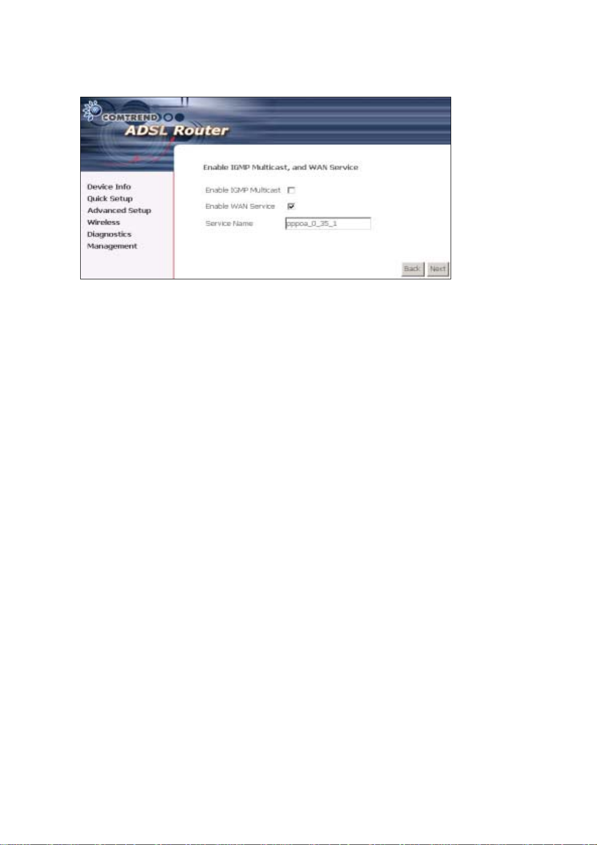
STEP 5: Click Next to display the following screen.
40
Page 42

Enable IGMP Multicast: Tick the checkbox to enable IGMP multicast (proxy).
IGMP (Internet Group Membership Protocol) is a protocol used by IP hosts to report
their multicast group memberships to any immediately neighboring multicast
routers.
Enable WAN Service:
Tick this item to enable the ATM service. Untick it to stop the ATM service.
Service Name: This is a user defined label.
STEP 6: Af ter ente r ing y our settings, se lect Next. The following screen appears.
41
Page 43

The Device Setup screen allows the user to configure the LAN interface IP address,
subnet mask, and DHCP server. T o enable DHCP, select Enable DHCP server and
enter starting and ending IP addresses and the leased time
Since the router occupies the first two IP addresses (192.168.1.1 and 192.168.1.2),
the default private address range provided by the ISP server in the router is
192.168.1.3 through 192.168.1.254.
If NAT is disabled, Enable DHCP Server Relay will be displayed as an option. T o
enable it, se lect th e Enable DHCP Server Relay radio button and enter the DHCP
Server IP Address. This allows the router to relay the DHCP packets from the remote
DHCP server. The remote DHCP server will provide the IP address.
To config ure a s econdary IP address for the LAN port, click the checkbox shown.
STEP 7: Click Next to continue. To enable the wireless function, select the radio
button (as shown) and input a new SSID (if desired).
Click Next to display the fina l setup sc reen.
42
Page 44

Step 9: The WAN Setup-Summary screen presents the proposed configuration.
Click Back to modify these settings . To apply these settings, click
Save/Reboot. The router will save the c onfiguration and reboot. After
the router reboots, the Web UI will refresh to the Device Info screen.
43
Page 45

4.2.2 MAC Encapsulation Routing
(MER)
Step 4: Select the MAC Encapsulat ion Rout ing (MER) radi o button and clic k Next.
Enter information provided to you by your ISP to configure the WAN IP settings.
NOTE: DHCP can be enabled for PVC in MER mode if Obtain an IP address
automatically is chosen. Changi ng the default gateway or the DNS
affects the whol e system. Configur ing them with stat ic va lues wi ll disab le
the automatic assignment from DHCP or other WAN connection.
If you configure static default gateway over this PVC in MER mode, you
must enter the IP address of the remote gateway in the “Use IP address”
field. Your ISP should provide the values to be entered in these fields.
Step 5: Click Next to display the following screen.
44
Page 46

Enable NAT
If the LAN is configured with a private IP address, the user should select this
checkbox. The NA T submenu will disp lay after the ne xt reboot. The user can then
configure NA T- related features. If a private IP address is not used on the LAN side,
this checkbox should not be selected so as to free up system resources.
Enable Fullcone NAT: This option becomes available when NAT is enabled
Known as one-to-one NAT, all requests from the same internal IP address and port
are mapped to the sam e e xterna l I P addre ss an d port . An e xterna l h ost ca n send a
packet to the internal host, by sending a packet to the mapped external address.
Enable Firewall
If the firewal l checkbo x is select ed, the Se curity submenu wil l display a fter the nex t
reboot. The user can then configure firewall features. If the firewall is not used,
this checkbox should not be selected so as to free up system resources.
Enable IGMP Multicast: Tick the checkbox to enable IGMP multicast (proxy).
IGMP (Internet Group Membership Protocol) is a protocol used by IP hosts to report
their multicast group memberships to any immediately neighboring multicast
routers.
Enable WAN Service:
Tick this item to enable the ATM service. Untick it to stop the ATM service.
Service Name: This is a user defined label.
Step 6: Click Next to display the following screen.
45
Page 47

The Device Setup screen allows the user to configure the LAN interface IP address,
subnet mask, and DHCP server. T o enable DHCP, select Enable DHCP server and
enter starting and ending IP addresses and the leased time.
Since the router occupies the first two IP addresses (192.168.1.1 and 192.168.1.2),
the default private address range provided by the ISP server in the router is
192.168.1.3 through 192.168.1.254.
If NAT is disabled, Enable DHCP Server Relay will be displayed as an option. T o
enable it, se lect th e Enable DHCP Server Relay radio button and enter the DHCP
Server IP Address. This allows the router to relay the DHCP packets from the remote
DHCP server. The remote DHCP server will provide the IP address.
To config ure a s econdary IP address for the LAN port, click the checkbox shown.
Step 7: Click Next to continue. To enable the wireless function, select the radio
button (as shown) and input a new SSID (if desired).
46
Page 48

Click Next to display the fina l setup sc reen.
Step 8: The WAN Setup-Summary screen presents the proposed configuration.
Click Back to modify these settings . To apply these settings, click
Save/Reboot. The router will save the c onfiguration and reboot. After
the router reboots, the Web UI will refresh to the Device Info screen.
47
Page 49

4.2.3 IP Over ATM
Step 4: Select the IP over ATM (IPoA) radio button and click Next.
NOTE: DHCP is not supported over IPoA. The user must enter the IP address or
WAN interface for the default gateway setup and the DNS server
addresses provided by their ISP.
Step 5: Click Next to display the following screen.
48
Page 50

Enable NAT
If the LAN is configured with a private IP address, the user should select this
checkbox. The NAT submenu will display after the next reboot. The user can then
configure NA T- related features. If a private IP address is not used on the LAN side,
this checkbox should not be selected so as to free up system resources.
Enable Fullcone NAT: This option becomes available when NAT is enabled
Known as one-to-one NAT, all requests from the same internal IP address and port
are mapped to the sam e e xterna l I P addre ss an d port . An exte rnal h ost ca n send a
packet to the internal host, by sending a packet to the mapped external address.
Enable Firewall
If the firewal l checkbo x is select ed, the Security sub menu wil l displa y after the ne xt
reboot. The user can then configure firewall features. If the firewall is not used,
this checkbox should not be selected so as to free up system resources.
Enable IGMP Multicast: Tick the checkbox to enable IGMP multicast (proxy).
IGMP (Internet Group Membership Protocol) is a protocol used by IP hosts to report
their multicast group memberships to any immediately neighboring multicast
routers.
Enable WAN Service:
Tick this item to enable the ATM service. Untick it to stop the ATM service.
Service Name: This is a user defined label.
Step 6: Click Next to display the following screen.
49
Page 51

The Device Setup screen allows the user to configure the LAN interface IP address,
subnet mask, and DHCP server. T o enable DHCP, select Enable DHCP server and
enter starting and ending IP addresses and the leased time.
Since the router occupies the first two IP addresses (192.168.1.1 and 192.168.1.2),
the default private address range provided by the ISP server in the router is
192.168.1.3 through 192.168.1.254.
If NAT is disabled, Enable DHCP Server Relay will be displayed as an option. T o
enable it, se lect th e Enable DHCP Server Relay radio button and enter the DHCP
Server IP Address. This allows the router to relay the DHCP packets from the remote
DHCP server. The remote DHCP server will provide the IP address.
To config ure a s econdary IP address for the LAN port, click the checkbox shown.
STEP 7: Click Next to continue. To enable the wireless function, select the radio
button (as shown) and input a new SSID (if desired).
50
Page 52

Click Next to display the fina l setup sc reen.
Step 8: The WAN Setup-Summary screen presents the proposed configuration.
Click Back to modify these settings . To apply these settings, click
Save/Reboot. The router will save the c onfiguration and reboot. After
the router reboots, the Web UI will refresh to the Device Info screen.
4.2.4 Bridging
Step 4: Select the ridging radio button and click Next. The followi ng s creen
appears. Select Enable Bridge Service and click Next.
51
Page 53

Step 5: On this screen, you can change the LAN IP address of the router.
NOTE: In bridge mode, the router is not associated with a WAN IP address. This
means that it can only be managed from a PC on the LAN. For remote
management, you must select a routing type (PPPoE/A, MER, or IPoA).
52
Page 54

STEP 6: Click Next to continue. To enable the wireless function, select the radio
button (as shown) and input a new SSID (if desired).
Click Next to display the fina l setup sc reen.
Step 7: The WAN Setup-Summary screen presents the proposed configuration.
Click Back to modify these settings . To apply these settings, click
Save/Reboot. The router will save the c onfiguration and reboot. After
the router reboots, the Web UI will refresh to the Device Info screen.
53
Page 55

Chapter 5 Device Information
The web user interface window is divided into two frames, the main menu (at le ft)
and the display screen (on the right). The main menu has several options and
selecting each of these options opens a submenu with more selections.
NOTE: The menu items shown are based upon the conf igured conne ction(s) and
user account privileges. For example, if NAT and Firewa ll are enabled, the
main menu will display the NAT and Security submenus. If either is
disabled, their corresponding menu(s) will also be disabled.
Device Info is the first selection on the main menu so it will be discussed first.
Subsequent chapters will introduce the other main menu options in sequence.
The Device Info Summary screen displays at startup.
This screen shows hardware, software, IP settings and other related information.
54
Page 56

5.1 WAN
Select WAN from the Devic e Inf o submenu to di splay the configured PVC( s).
Port/VPI/VCI Shows the values of the ATM VPI/VCI
VLAN Mux Shows 802.1Q VLAN ID
Con. ID Shows the connection ID
Category Shows the ATM service classes
Service Shows the name for WAN connection
Interface Shows connection interfaces
Protocol Shows the connection type, such as PPPoE, PPPoA, etc.
IGMP Shows the status of IGMP
NAT Shows the status of NAT
Firewall Shows the status of the Firewall
State Shows the connection state of the WAN connect i on
Status Lists the status of DSL link
IPv4 Address Shows WAN IPv4 address
55
Page 57

5.2 Statistics
This selection provides LAN, WAN, ATM and ADSL statistics.
NOTE: These screens are updated every 15 seconds.
5.2.1 LAN Statistics
This screen shows data traffic statist ics f or ea ch LAN int erf a c e.
Heading Description
Interface LAN interface(s)
Received/Transmitted: - ytes
- Pkts
- Errs
- Drops
Number of bytes
Number of packets
Number of packets with errors
Number of dropped packets
56
Page 58

5.2.2 WAN Statistics
This screen shows data traffic statist ics f or ea ch WAN interface.
Service Shows the service type
VPI/VCI Shows the values of the ATM VPI/VCI
Protocol Shows the connection type, such as PPPoE,
PPPoA, etc.
Interface Shows connection interfaces
Received/Transmitte d - ytes
- Pkts
- Errs
- Drops
Heading Description
Interface WAN interfaces
Description WAN serv ice labe l
Receiv ed/Transmi tted - ytes
- Pkts
- Errs
- Drops
Rx/TX (receive/transmit) packets in bytes
Rx/TX (receive/transmit) packets
Rx/TX (receive/transmit) packets with errors
Rx/TX (receive/transmit) dropped packets
Number of bytes
Number of packets
Number of packets with errors
Number of dropped packets
57
Page 59

5.2.3 ATM Statistics
The following figure shows Asynchronous Transfer Mode (ATM) statistics.
ATM Interface Statistics
Heading Description
In Octets Number of received octets over the interface
Out Octets Number of transmitted octets over the interface
In Errors Number of cells dropped due to uncorrectable HEC errors
In Unknown Number of received cells discarded during cell header validation,
including cells with unrecognized VPI/VCI values, and cells with
invalid cell header patterns. If cells with undefined PTI values
are discarded, they are also counted here.
In Hec Errors Number of cells received with an ATM Cell Header HEC err or
In Invalid Vpi
Vci Errors
In Port Not
Enable Errors
In PTI Errors Number of cells received with an ATM header Payload Type
In Idle Cells Number of idle cells rece ived
In Circuit Type
Errors
In OAM RM CRC
Errors
In GFC Errors Number o f cells received with a non-zero GFC.
Number of cells received with an unregistered VCC address.
Number of cells received on a port that has not been enabled.
Indicator (PTI) error
Number of cells received with an ill egal circuit type
Number of OAM and RM cells received with CRC errors
58
Page 60

AAL5 Interface Statistics
Heading Description
In Octets Nu mber of received AAL5/AAL0 CPCS PDU octets
Out Octets Number of received AAL5/AAL0 CPCS PDU octets transmitted
In Ucast Pkts Number of received AAL5/AAL0 CPCS PDUs passed to a
higher-layer for transmi ss ion
Out Ucast Pkts Number of received AAL5/AAL0 CPCS PDUs received from a
higher layer for transmission
In Errors Number of rec eived AAL5/AAL0 CPCS PDUs received that
contain an error. These errors include CRC-32 errors.
Out Errors Number of received AAL5/AAL0 CPCS PDUs that could not be
transmitted due to errors.
In Discards Number of received AAL5/AAL0 CPCS PDUs discarded due to an
input buffer overflow condition.
Out Discards This field is not currently used
AAL5 VCC Statistics
Heading Description
VPI/VCI ATM Virtual Path/Channel Id ent ifiers
CRC Errors Number of PDUs received with C RC-32 errors
SAR TimeOuts Number of partially re-assembled PDUs that were discarded
because they were not fully re-assembled within the required
period of time. If the re-assembly time is not supported, then
this object contains a zero value.
Oversized SDUs Number of PDUs discarded because the corresponding SDU was
too large
Short Packet
Errors
Length Errors Number of PDUs discarded be cause the PDU length d id not
Number of PDUs discarded because the PDU length was less
than the size of the AAL5 trailer
match the length in the AAL5 trailer
59
Page 61

5.2.4 xDSL Statistics
Field Description
Mode Line Coding format, that can be selected G.dmt, G.lite,
T1.413, ADSL2
Type Channel type Interleave or Fast
Line Coding Trellis On/Off
Status Lists the status of the DSL link
Link Power State Link output power state.
PhyR Status: A new impulse noise protection technology that uses to
improve voice, data and video services.
SNR Margin (d) Signal to Noise Ratio (SNR) margin
Attenuation (d) Estimate of average loop attenua tion in the dow nstream
direction.
60
Page 62

Output Power (dm) To tal upstream output power
Attainable Rate (Kbps) The sync rate you would obtain.
Rate (Kbps) Current sync rate.
Super Frames Total number of super frames
Super Frame Errors Number of super fr ames received with err or s
RS Words Total number of Reed-Solomon code errors
RS Correcta ble Errors Total Number of RS with correctable errors
RS Uncorrectable Errors Total Number of R S words with uncorrectable errors
HEC Errors Total Number of Header Error Checksum errors
OCD Errors Total Number of out-of-cell Delineation errors
LCD Errors Total number of Loss of Cell Delineation
Total Cells: Total number of ATM cells (including id le and data cells)
Data Cells: Total number of ATM data cells
it Errors: Total number of bit errors
Total ES: Total Number of Errored Seconds
Total SES: Total Number of Severely Errored Seconds
Total UAS: Total Number of Unavailable Seconds
In G.DMT mode the following section is inserted.
K Number of bytes in DMT frame
R Number of check bytes in RS code word
S RS code word size in DMT frame
D The interleaver depth
Delay The delay in milliseconds (msec)
In ADSL2+ mode the following section is inserted.
MSGc Number of bytes in overhead channe l message
Number of bytes in Mux Data Frame
M Number of Mux Data Frames in FEC Data Frame
T Max Data Frames over s y nc bytes
R Number of check bytes in FEC Data Frame
S Ratio of FEC over PMD Data Frame length
L Number of bits in PMD Data Frame
D The interleaver depth
Delay The delay in milliseconds (msec)
In ADSL2+ mode the following section is inserted.
Total ES Total Number of Errored Seconds
Total SES Total Number of Severely Errored Seconds
Total UAS Total Number of Unavailable Seconds
61
Page 63

Within the ADSL Statistics window, a it Error Rate (ER) test can be s ta rted u s ing
the ADSL BER Test button. A small window will open when the button is pressed;
it will appear as shown below. Click Start to start the test or Close.
If the test is successfu l, the pop-up w indow w il l d isp la y as follows.
62
Page 64

5.3 Route
Choose Route to display the routes that the CT-5364A has found.
Field Description
Destination Destination network or destination host
Gateway Next hub IP address
Subnet Mask Subnet Mask of Destination
Flag U: route is up
!: reject route
G: use gateway
H: target is a host
R: reinstate route for dynamic routing
D: dynamically installed by daemon or redirect
M: modified from routing daemon or redirect
Metric The 'distance' to the target (usually counted in hops). It is not
used by recent kernels, but may be needed by routing daemons.
Service Shows the WAN connection label
Interface Shows connection interf a ce s
63
Page 65

5.4 ARP
Click ARP to display the ARP in formation.
Field Description
IP address Shows IP address of host pc
Flags Complete, Incomplete, Permanent, or Publish
HW Address Sho ws the MA C address of host pc
Device Shows the connection interface
5.5 DHCP
Click DHCP to display all DHCP Leases.
Field Description
Hostname Shows the device/host/PC network name
MAC Address Shows the Ethernet MAC address of the device/host/PC
IP Address Shows IP address of device/host/PC
Expires In Shows how much time is left for each DHCP Lease
64
Page 66

Chapter 6 Advanced Setup
This chapter explains the following screens:
6.1 WAN 6.88 DNS
02
LAN 6.99 DSL
6.33 NAT ᙑᎄ
ࠐᄭ
ࠐᄭΖ
Ζ
ࠐᄭࠐᄭ
ΖΖ
6.44 Security 6.101 Print Server
6.55 Parental Control 6.112 Interface Grouping
6.66 Quality of Service (QoS) ᙑᎄ
ࠐᄭ
ࠐᄭΖ
Ζ
ࠐᄭࠐᄭ
ΖΖ
6.77 Routing 6.124 IP Sec
You can add , ed it or re mo v e IPSe c tun nel mode connections from this p a ge.
ᙑᎄ! ބլࠩᅃࠐᄭ
ބլࠩᅃࠐᄭΖ
ᙑᎄᙑᎄ
ބլࠩᅃࠐᄭބլࠩᅃࠐᄭ
ᙑᎄ! ބլࠩᅃࠐᄭ
ބլࠩᅃࠐᄭΖ
ᙑᎄᙑᎄ
ބլࠩᅃࠐᄭބլࠩᅃࠐᄭ
Ζ0 ᙑᎄ
ᙑᎄ! ބլࠩᅃ
ΖΖ
Ζ3 ᙑᎄ
ΖΖ
ބլࠩᅃ
ᙑᎄᙑᎄ
ބլࠩᅃބլࠩᅃ
ᙑᎄ! ބլࠩᅃ
ބլࠩᅃ
ᙑᎄᙑᎄ
ބլࠩᅃބլࠩᅃ
Click Add New Connection to add a new IPSec termination rule .
The following screen will display.
65
Page 67

IPSec Connection Name User-defined label
Remote IPSec Ga tew a y Ad d re ss The location of the Remote IPSec Gatewa y. IP
address or domain name can be used.
Tunnel access from local IP
addresses
IP Address/Subnet Mask for VPN If you chose Single, please enter the host IP
Tunnel access from remote IP
addresses
IP Address/Subnet Mask for VPN If you chose Single, please enter the host IP
Key Exchange Method Select from Auto(IKE) or Manual
For the Auto(IKE) key ex change method, select Pre-shared key or Certificat e (X.509)
authentication. For Pre-shared key authentication you must enter a key, while for
Certificate (X.509) authentication you must select a certificate from the list.
See the tables below for a summary of all available options.
Auto(IKE) Key Exchange Method
Pre-Shared K ey / Certificate (X.509) Input Pre-shared key / Choose Certificate
Perfect Forward Secrecy Enable or Disable
Specify the acceptable host IP on the local
side. C hoose Single or Subnet.
address for VPN. If you chose Subnet, please
enter the subnet information for VPN.
Specify the acceptable host IP on the remote
side. Choose Single or Subnet.
address for VPN. If you chose Subnet
enter the subnet information for VPN.
, please
66
Page 68

Advanced IKE Settings Select Show Advanced Settings to reveal
the advanced settings options shown below.
Advanced IKE Settings Select Hide Advanced Settings to hide the
advanced settings options shown above.
Phase 1 / Phase 2 Choose settings for each phase, the available
options are separated with a “/” character.
Mode Main / Aggressive
Encryption Algorithm DES / 3DES / AES 128,192,256
Integrity Algorithm MD5 / SHA1
Select Diffie-Hellman Group 768 – 8192 bit
Key Life Time Enter your own or use the default (1 hour)
The Manual key exchange method options are summarized in the table below.
Manual Key Exchange Method
Encryption Algorith m DES / 3DES / AES (aes-cbc)
Encryption Key DES: 16 digit Hex, 3DES: 48 digit Hex
Authentication Algorithm MD5 / SHA1
Authentication Key MD5: 32 digit Hex, SHA1: 40 digit Hex
SPI (default is 101) Enter a Hex value from 100-FFFFFFFF
67
Page 69

Certificate
6.1 WAN
This screen allows for the adv anced configuration of WAN interfac es.
• To Add a WAN connection, click the Add button. To edit an existing connect ion,
click the Edit button next to the connection. T o complete th e Add or Edit, on the
opening screen, select VLAN Mux ( see sect ion
5.1.1) and then proceed to STEP
68
Page 70

2 in section Manual Quick Setup.
• T o remov e a connect ion select its radio butt on under the Remove column in the
table and click the Remove button under the table.
• Save/Reboot activates the new configuration.
VPI/VCI VPI (0-255) / VCI (32-65535)
VLAN Mux Shows 802.1Q VLAN ID
Con. ID ID for WAN connection
Category ATM servi ce ca te g ory, e.g. UR, CR…
Service Name of the WAN connection
Interface Name of the interface for WAN
Protocol Shows bridge or router mod e
IGMP Shows enable or disable IGMP proxy
NAT Shows enable or disable NAT
Firewall Shows enable or disabl e Firewall
QoS Shows enable or disable QoS
State Shows enable or disable WAN connection
Remove Select or deselect the connection for removal
Edit Click Edit to change connection settings
6.1.1 VLAN Mux
VLAN Mux is a form of VLAN tagging that allows multiple protocols over a single
connection. It is espec i al ly us ef u l fo r VD SL 2 c on n ec t ion s in pa c ket t r a ns f er mod e.
This option is found on the Advanced WAN Setup screen. This is the first screen
you will see when adding or editing a connection. VLAN Mux can be enabled by
selecting the VLAN Mux – Enable Multiple Protocols Over a Single PVC check
box, outlined in red below. Enter a value between 0 and 4095 for 802.Q VLA N ID.
69
Page 71

After proceeding to STEP 3 in se ction Manual Quick Se tup, the scr een will appear as
follows. Notice that PPPoA and IPoA are not available.
70
Page 72

PVCs can be added using the regular procedure, however, now multiple protocols
can exist over the same connection, as long as the 802.1Q VLAN IDs differ.
The graphic below shows an example of three protoco ls o v er the same connection.
6.1.2 MSP
Multi-Serv ice o ve r PVC ( MSP) support s mu ltip le prot oc ols over a single conne ct ion.
As with the VLAN Mux funct ion, PPP oE, ridge and MER protocols can coexist, while
IPoA and PPPoA are not supported. This function supports remote management by
bridge protocol in addition to multimedia applications over a single PVC.
Configuring MSP is a two-part process:
Part 1 - Create mult iple P VCs (One ridge + multiple PP P o E / One MER)
Part 2 - Use Port Mapping to connect LAN / WAN interfaces
The following example shows how to configure a ridge / PPPoE MSP connection.
The same process can be used for ridge / MER MSP connections.
NOTE: If QoS is configured on the first MSP connection, it will be configured by
default for all subsequent connections.
If a MSP connection is removed every other MSP connection should be
removed to avoid port mapping configuration problems.
Part 1 – Create Multiple PVCs
On the Advanced Setup – WAN screen, create one PPPoE connection and one ridge
connection on the MSP supporting PVC. The screen will display as follows.
71
Page 73

Part 2
Go to Advanced Setup – Interface Group screen and select the Enable Virtual
Ports checkbox. The screen will disp lay as follows.
NOTE: Only the ridge PVC is shown on the P ort Mapp ing config ur at ion. It is in
72
Page 74

the format of “ nas_x_y_z” where x=port, y=vpi, and z=vci.
T o continue, clic k the Add button at the bottom of the screen shown above. On the
next screen, select the bridge connection and one Ethernet virtual port (ENET 1-4)
and enter a Group Name, such as “MSP1”, as shown below. Click Save/Apply.
If successfully configured, the Port Mapping screen will display as follows.
NOTE: If you wish to maintain local access to the web user interface, avoid
grouping the Ethernet interface that is attached to the host PC.
73
Page 75

6.2 LAN
Configure local area network (LAN) settings here.
74
Page 76

Consult the field descriptions below for more details.
GroupName: Select an Interface Group.
st
LAN INTERFACE
1
IP Address: Enter the IP address for the LAN port.
Subnet Mask: Enter the subnet mask for the LAN port.
Enable UPnP: Tick the box to enable Universal Plug and Play.
This option is hidden when NAT disabled or if no PVC exists
Force IGMP Proxy version on WAN side: V2 is selected by default. Select V3 if
required.
Enable IGMP Snooping: Enable by ticking the checkbox ;.
75
Page 77

Standard Mode: In standard mode, multicast traffic will flood to all
bridge ports when no client subscribes to a multicast
group – even if IGMP snooping is enabled.
locking Mode: In blocking mode, the multicast data traffic will be
blocked and not flood to all bridge ports when there are
no client subscriptio ns to any multicast gro up.
Enhanced IGMP: When enabled, IGMP pac kets will not flood to all bridge ports.
Allowed Mac Address: Displays the MAC address(es) allowed to pass throughput
LAN interface.
DHCP Server: Enable with checkbox ; and enter DHCP Server IP address.
This allows the Router to relay the DHCP packets to the
remote DHCP server. The remote DHCP server will provide
the IP address. This option is hidden if NAT is enabled or
when the router is configured with only one Bridge PVC.
Static IP Lease List: A maximum 32 entries can be conf ig ur e d.
To add an entry, enter MAC address and Static IP and then click Save/Apply.
To remove an entry, tick the corresponding checkbox ; in the Remove co lumn and
then click the Remove Entries button, as shown below.
DHCP Server Relay: Enable with
checkbox and enter DHCP Server IP address. This allows
the Router to relay the DHCP packets to the remote DHCP
server . The remote DHCP server will provide the IP addr ess.
This option is hidden if NAT is enabled
76
Page 78

ND
2
LAN INTERFACE
To configure a secondary IP address, tick the checkbox ; outlined ( in RED) below.
IP Address: Enter the secondary IP address for the LAN port.
Subnet Mask: Enter the secondary subnet mask for the LAN port.
NOTE: The Save button saves new settings to allow co nt inue d configuration
while the Save/Reboot button not only saves new settings but also
reboots the device to apply the new configuration (i.e. all new settings).
Ethernet Media Ty pe: Select from Auto, 10_Half , 10_Full, 100_Half or 100_Full
for each Ethernet port.
6.3 NAT
To display this option, NAT must be enabled in at least one PVC shown on the
Advanced Setup - WAN screen. ( NAT is not an available option in Bridge mode)
77
Page 79

6.3.1 Virtual Servers
Virtual Servers a llow yo u to dire ct incomi ng traffic from the W AN side (i dentified by
Protocol and External port) to the Internal server with private IP addresses on the
LAN side. The Internal port is required only if the external port needs to be
converted to a different port number used by the server on the LAN side.
A maximum of 32 entries can be configured.
To add a Virtual Server, click Add. The following will be displayed.
Consult the table below for field and header descriptions.
Field/Header Description
Select a Service
Or
Custom Server
Server IP Address Enter the IP address for the server.
User should select the service from the list.
Or
User can enter the name of their choice.
78
Page 80

Field/Header Description
External Port Start Enter the starting external port number (when you select
Custom Server). When a service is selected, the port ranges
are automatically configured.
External Port End Enter the ending external port number (when you select
Custom Server). When a service is selected, the port ranges
are automatically configured.
Protocol TCP, TCP/UDP, or UDP.
Internal Port Sta rt Enter the internal port starting number (when you select
Custom Server). When a service is selected the port ranges
are automatically configured
Internal Port End Enter the internal port ending number (when y o u sele ct
Custom Server). When a service is selected, the port ranges
are automatically configured.
6.3.2 Port Triggering
Some applications require that specific ports in the firewall be opened for access by
the remote partie s. Port Triggers dynamically ' Op e n P o rts' in the firewa ll w hen an
application on the LAN initiates a TCP/UDP connection to a remote party using the
'Triggering Ports'. The Router allows the remote party from the WAN side to
establish new connections back to the application on the LAN side using the 'Open
Ports'. A maximum 32 entries can be configured.
To add a Trigger Port, click Add. The follo wing w il l b e disp la yed.
79
Page 81

Consult the table below for field and header descriptions.
Field/Header Description
Use Interface Select the WAN interface from the drop-down box.
Select an Application
Or
Custom Application
Trigger Po rt Star t Enter the start ing tr igger port numb er (when yo u sele ct
Trigger Port End Enter the ending trigger port number (when you select
Trigger Protocol TCP, TCP/UDP, or UDP.
Open Port Start Enter the starting open port number (when you select
Open Port End Enter the ending open port number (when you select
Open Protocol TCP, TCP/UDP, or UDP.
User should select the application from the list.
Or
User can enter the name of their choice.
custom appl ication). When an application is se lected, the
port ranges are automatically configured.
custom appl ication). When an application is se lected, the
port ranges are automatically configured.
custom appl ication). When an application is se lected, the
port ranges are automatically configured.
custom appl ication). When an application is se lected, the
port ranges are automatically configured.
6.3.3 DMZ Host
The DSL router will forward IP packets from the WAN that do not belong to any of
the applications configured in the Virtual Ser v er s tab le to the DMZ host computer.
80
Page 82

To Activate the DMZ host, enter the DMZ host IP address and click Save/Apply.
To Deactivate the DMZ host, clear the IP address field and click Save/Apply.
6.3.4 ALG
SIP (Session Initiation Protocol, RFC3261) is the protocol of choice for most VoIP
(Voice over IP) devices to initiate communication. A SIP ALG (Application Layer
Gateway) as sists V oIP packet t raffic fr om a SIP-compl iant IP phone or VoIP gateway
to passthrough a NAT enabled router.
To enable the SIP ALG select the SIP Enabled checkbox and click Save/Apply.
NOTE: ALG is only valid for SIP protocol running on UDP port 5060.
81
Page 83

6.4 Security
To display this function, you must enable the firewall feature in WAN Setup.
For detailed descriptions, with examples, please consult Appendi x A - Firewall.
6.4.1 IP Filtering
This screen sets filter rules that limit IP traffic (Outgoing/Incoming). Multiple filter
rules can be set and each appli es at lea st one li miting condition. For individual IP
packets to pass the fi lter all conditions must b e fulfilled.
NOTE: This function is not available when in bridge mode. Instead,
(pg. 61) performs a similar function.
OUTGOING IP FILTER
y default, all outgoing IP traffic is allowed, but IP traffic can be blocked with filters.
MAC Filter ing
ڤ֏
ڤ֏ˍˍˍˍʳᙌؾ༼ق
ڤ֏ڤ֏
To add a filter (to block some outgoing IP traffic), click the Add button.
On the following screen, enter your filter criteria and then click Apply/Save.
82
Page 84

Consult the table below for field descriptions.
Field Description
Filter Name The filter rule label
Protocol TCP, TCP/UDP, UDP, or ICMP.
Source IP address Enter source IP address.
Source Subnet Mask Enter source subnet mask.
Source Port (port or port:port) Enter source port number or range.
Destination IP address Enter destination IP address.
Destination Subnet Mask Enter destination subnet mask.
Destination Port (port or port:port) Enter destination port number or range.
INCOMING IP FILTER
y default, all incoming IP t raffic is bloc ked, but IP tra ffic can be allo wed with filters.
To add a filter (to allow incoming IP traffic), click the Add button.
On the following screen, enter your filter criteria and then click Apply/Save.
Consult the table below for field descriptions.
83
Page 85

Field Description
Filter Name The filter rule label
Protocol TCP, TCP/UDP, UDP, or ICMP.
Source IP address Enter source IP address.
Source Subnet Mask Enter source subnet mask.
Source Port (port or port:port) Enter source port number or range.
Destination IP address Enter destination IP address.
Destination Subnet Mask Enter destination subnet mask.
Destination Port (port or port:port) Enter destination port number or range.
At the bottom of this screen, select the WAN and LAN Interfaces to which the filter
rule will app ly . Y ou ma y select all or just a subse t. WAN int erfaces in b ridge mode or
without firewall enabled are not available.
6.4.2 MAC Filtering
NOTE: This option is only a vaila ble in brid ge mode. O ther modes use IP Filtering
(pg. 59) to perform a similar function.
Each network device has a unique 48-bit MAC address. This can be used to filter
(block or forward) packets based on the originating device. MAC filtering policy
and rules for the CT-5364A can be set according to the following procedure.
The MAC Filtering Global Policy is defined as follows. FORWARDED means that all
MAC layer fra mes will be FORWARDED except those matching the MAC filter rules.
BLOCKED means that all MAC layer frames will be BLOCKED except those
matching the MAC filter rules. The default MAC Filtering Global policy is
FORWARDED. It c an be changed by clicking the Change Policy button.
Choose Add or Remove to configure MAC filtering rules. The following sc re en wi ll
appear when you click Add. Create a filter to identify the MAC layer frames by
specifying at least one condition below. If multiple conditions are specified, all of
them must be met. Click Save/Apply to save and activate the filter rule.
84
Page 86

Consult the table below for detailed field descriptions.
Field Description
Protocol Type PPPoE, IPv4, IPv6, AppleTalk , IPX , NetEUI, IGMP
Destination MAC Address Defines the destination MAC address
Source MAC Address Defines the source MAC address
Frame Direction Select the incoming/outgoing packet interface
WAN Interfaces Applies the filter to selected WAN int e rf aces in bridge
mode. These rules are arranged according to these
interfaces, as shown under the Interface heading on
the previous screen.
6.5 Parental Control
This selection pro v id es WAN access contro l fun ct io n a l it y.
6.5.1 Time of Day Restrictions
This feature restricts access from a LAN device to an outside network through the
device on selected days at certain times. Make sure to activa t e the In t erne t T ime
server synchronization as described in section 9.5, so that the scheduled times
match your local time.
ڤ֏
ڤ֏ˍˍˍˍʳᙌؾ༼ق
ڤ֏ڤ֏
85
Page 87

Click Add to display the following screen.
See below for field descriptions. Click Save/Apply to add a time restriction.
User Name: A user- defined la bel for this restriction.
Browser's MAC Address: MAC address of the PC running the browser.
Other MAC Address: MAC address of another LAN device.
Days of the Week: The days the restrictions apply .
Start Blocking Time: The time the restrictions start.
End Blocking Time: The time the restricti ons end.
86
Page 88

6.5.2 URL Filter
This screen allo ws for the creation of a filter rule for access right s to websites bas ed
on their URL address and port number.
Click Add to display the following screen.
Enter the URL address and port number then click Save/Apply to ad d the e ntry t o
the URL filter. URL Addresses begin with “www” , as shown in this example.
A maximum of 100 entries can be added to the URL Filter list.
Tick the Exclude radio button to deny access to the websites listed.
Tick the Include radio button to rest r i ct access to only those listed we bs ites.
87
Page 89

6.6 Quality of Service (QoS)
NOTE: QoS must be enabled in at least one PVC to display this option.
6.6.1 Queue Management
Configuration
To Enable QoS tick the checkbox ; and select a Default DSCP Mark.
Click Save/Apply to activate QoS.
QoS and DSCP Mark are defined as follows:
Quality of Service (QoS): This provides different priority to different users or data
flows, or guarantees a certain level of performance to a data flow in accordance with
requests from Queue Prioritization.
Default Differentiated Services Code Point (DSCP) Mark: This specifies the
per hop behavior for a given flow of packets in the Internet Protocol (I P) header that
do not match any other QoS rule.
6.6.2 Queue Configuration
This function follow s the Differentiated Servic es rule of IP QoS. Y ou can create a new
Queue entry by clicking the Add button. Enable and assign an interface and
precedence on the next screen. Click Save/Reboot on this screen to activate it.
88
Page 90

Click Add to display the following screen.
Queue Configuration Status: Select Enable or Disable the Queue entry.
Queue: Assign queue to a specific network interface with QoS enabled.
Queue Precedence: Configure precedence for the Queue entry. Lower integer
values for precedence imply higher priority for this entry relative to others.
89
Page 91

6.6.3 QoS Classification
The network traffic classes are listed in the following table.
Click Add to configure a network traffic clas s rule and Enable to activate it. To
delete an entry from the list, click Remove.
This screen creates a traffic class rule to classify the upstream traffic, assign
queuing priority and optionally overwr ite the I P header DS CP byte. A rule con sists of
a class name and at least one logical condition. All the conditions specified in the
rule must be satisf ied f or it t o tak e effect.
Click Save/Apply to save and activate a rul e.
Field Description
Traffic Class Name Enter a name for the traffic class.
90
Page 92

Field Description
Rule Order Last or null are the only options.
Rule Status Disable or enable the rule.
Assign Cl as sification
Queue
The queue configurations are presented in this format:
“Interfacename&Prece P
&Queue Q” where P and Q are the
Precedence and Queue Key values for the corresponding
Interface as liste d on the Queue Co n fig screen.
Assign Differentiated
Services Code Po int
The selected Code Point gives the corresponding priority to
the packets that satisfies the rules set below.
(DSCP) Mark
Mark 802.1p if
802.1q is enabled
Select between 0-7. The lower the digit shows the higher
the priority.
SET-1
Physical LAN Port: Select eth0-eth4 or Wlan from the dropdown menu.
Protocol TCP, TCP/UDP, UDP, or ICMP.
Differentiated
Services Code Po int
The selected Code Point gives the corresponding priority to
the packets that satisfies the rules set below.
(DSCP) Check
IP Address Select IP Address, Vendor Class ID (DHCP Option 60), or
User Class ID (DHCP Option 77)
Source Subnet Mask Enter the subnet mask for the source IP address.
UDP/TCP Source Port
Enter source port number or port range.
(port or port:port)
Destination IP
Enter destination IP address.
address
Destination Subnet
Enter destination subnet mask.
Mask
UDP/TCP Destination
Enter destination port number or port range.
Port (port or
port:port)
Source MAC Address A packet belongs to SET -1, if a b inary-AN D of its s ource MAC
address with the Source MAC Mask is equal to the
binary-AND of the Source MAC Mask and this field.
Source MAC Mask This is the mask used to decide how many bits are checked
in Source MAC Address.
Destination MAC
Address
A packet belongs to SET -1 then the result that the
Destination MAC Address of its header binary-AND to the
Destination M AC Mask must equal to t he result that this field
binary-AND to the Destination MAC Mask.
Destination MAC
Mask
This is the mask used to decide how many bits are checked
in Destination MA C Addr e s s.
SET-2
802.1p Priority Select between 0-7. The lower the digit shows the higher
the priority
91
Page 93

6.7 Routing
This option controls Default Gateway, Static Route, Policy Routing and RIP.
NOTE: In bridge mode, the RIP screen is hidden while the other configuration
screens are shown but ineffective.
6.7.1 Default Gate w ay
If Enable Automatic Assigned Defa ult Gateway checkbox is selected, this router will
accept the first re ceive d defa ult gat eway a ssignme nt from one of the PPP oA, PP PoE
or MER/DHCP enabled PVC(s). If the checkbox is not sel ected, enter the static
default gateway AND/OR a WAN interface. Click 'Save/Apply' button to save it.
NOTE: After enabling the Automatic Assigned Default Gateway , the device must
be rebooted to activate the assigned default gateway.
92
Page 94

6.7.2 Static Route
This option allows f or th e conf ig u r ation of static routes by destination IP.
Click Add to create a static route or click Remove to delete a static route.
Click the Add button to display the following screen.
Enter Destination Network Address, Subnet Mask, Gateway IP Address, and/or WAN
Interface. Then, click Save/Apply to add the entry to the routing table.
93
Page 95

6.7.3 RIP
To activate RIP, configure the RIP version/operation mode and select the Enabled
checkbox ; for at least one W AN int e rfa c e bef o re cl icking Save/Apply.
6.8 DNS
6.8.1 DNS Server
If 'Enable Automat ic Assigned DNS' che ckbox is se lected, this route r will accept th e
first received DNS assignment from one of the PPPoA, PPPoE or MER/DHCP enabled
PVC(s) during the connection establishment. If the checkbox is not selected, enter
the primary and optiona l secondary DN S serve r IP addresse s. Click 'Sa ve' but ton to
save the new configuration. You must reboot the router to make the new
configuration effective.
94
Page 96

6.8.2 Dynamic DNS
The Dynamic DNS service allows you to map a dynamic IP address to a static
hostname in any of many domains, allowing the CT-5364A to be more easily
accessed from var ious locations on the Internet.
To add a dynamic DNS service, click Add. The following screen will display.
Consult the table below for field descriptions.
Field Description
D-DNS provider Select a dynamic DNS provider from the list
Hostname Enter the name of the dynamic DNS server
Interface Select the interface from the list
Username Enter the username of the dynamic DNS server
Password Enter the password of the dynamic DNS server
95
Page 97

6.9 DSL
The DSL Settings screen allows for the selection of DSL modulation modes.
For optimum performance, the modes selected should match those of your ISP.
DSL Mode Data Transmission Rate - Mbit/s (Megabits per second)
G.Dmt Downstream: 12 Mbit/s Upstream: 1.3 Mbit/s
G.lite Dow nstream: 4 Mbit/s Upstream: 0.5 Mbit/s
T1.413 Downstream: 8 Mbit/s Upstream: 1.0 Mbit/s
ADSL2 Downstream: 12 Mbit/s Upstream: 1.0 Mbit/s
AnnexL Supports longer loops but with reduced t r a nsmission rates
ADSL2+ Downstream: 24 Mbit/s Upstream: 1.0 Mbit/s
AnnexM Downstream: 24 Mbit/s Upstream: 3.5 Mbit/s
Options Description
Inner/Outer Pair Select the inner or outer pins of the twisted pair (RJ11 cable)
itswap Enable Enables adaptive handshaking functionality
SRA Enable Enables Seamless Rate Adap tation (SRA)
96
Page 98

6.10 Print Server
The CT-5364A provides printer support through a high-speed US2.0 host port.
Please refer to Appendix E for detailed installation instructions.
97
Page 99

6.11 Interface Grouping
Interface Grouping supports multiple ports to PVC and bridging groups. Each group
performs as an independent network. T o use this fea ture, you must create mapping
groups with appropriate LAN and WAN interfaces using the Add button.
The Remove button removes mapping groups, returning the ungrouped interfaces
to the Default group. Only the default group has an IP interface.
To add an Interface Group, click the Add button. The following screen will appear.
It lists the available and grouped interfaces. Follow the instructions shown here.
NOTE: To assign Ethernet Ports ENET(1-4) to separate Interface Groups, the
VLAN Port feature must be activated. See section ᙑᎄ
for details.
ᙑᎄ! ބլࠩᅃࠐᄭ
ބլࠩᅃࠐᄭΖ
ᙑᎄᙑᎄ
ބլࠩᅃࠐᄭބլࠩᅃࠐᄭ
Ζ
ΖΖ
ڤ֏
ڤ֏ˍˍˍˍʳᙌؾ༼ق
ڤ֏ڤ֏
98
Page 100

DHCP Vendor IDs
Add support to automatically map LAN interfaces using DHCP vendor ID (option 60).
The local DHCP server will forward these types of requests to a remote DHCP server .
For example, imagine there are 4 PVCs (0/33, 0/36, 0/37, 0/38), VPI/VCI=0/33 is
for PPPoE while the other PVCs are for IP set-top box use, and the LAN interfaces are
ENET1, ENET2, ENET3, and ENET4. The Interface Grouping configuration will be:
1. Default: ENET1, ENET2, ENET3, and ENET4.
2. Video: nas_0_36, nas_0_37, and nas_0_38. The DHCP vendor ID is "Video".
The local DHCP server is running on "Default" and the remote DHCP server is
running on PVC 0/36 (i.e. for set-top box use only). LAN side clients can get IP
addresses from the CPE's DHCP server and access the Internet via PPPoE (0/33).
If a set-top box is conn ecte d to EN ET1 and sen ds a DH CP req uest with ve ndor ID
"Video", the local DHCP server will forward this request to the remote DHCP server .
The Interface Grouping configuration will automatically cha nge to the following:
1. Default: ENET2, ENET3, and ENET4.
2. Video: nas_0_36, nas_0_37, nas_0_38, and ENET1.
99
 Loading...