

Page 1
20 Meter
Vertical
Antenna
COM-20VA
COM-20VA-INS-Revision 2
COMTEK SYSTEMS 2016
1200 Southeast Ave. - Tallmadge, OH 44278 USA
Phone: (800) 777-0703
Technical Support and International: (330) 572-3200
Fax: (330) 572-3279
E-mail: [email protected]
- 1 -
Page 2
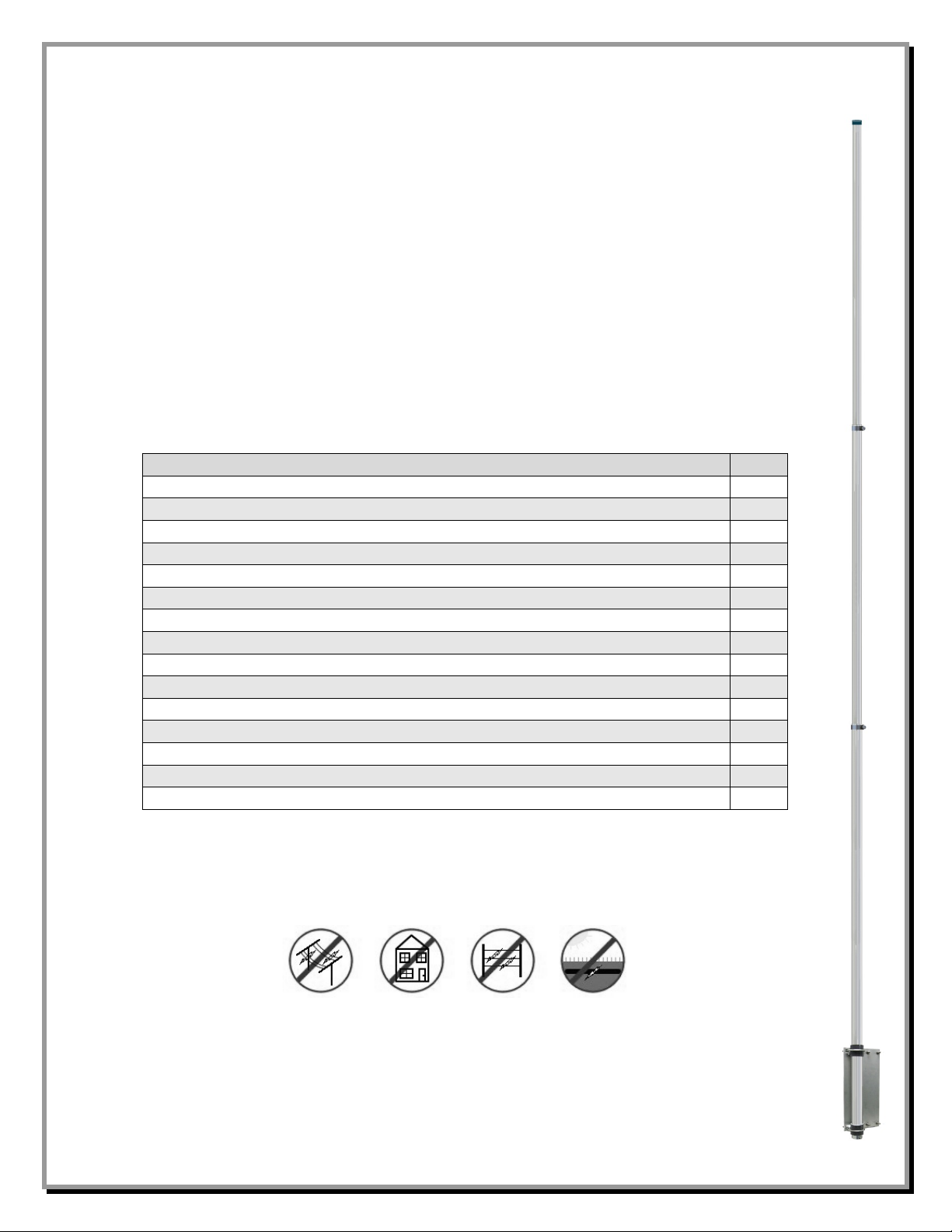
Congratulations! You are now the proud owner of a Comtek 20 Meter Vertical Antenna. This
Description
QTY
Aluminum Mounting Plate, 7-1/2" x 5-17/32" x 1/4", Drilled
1
Element Insulator, EXTREN®, 1.5" OD x 1" ID x 2" long, Split
2
Aluminum Cast Saddle 1.5", for Element Insulator
2
Stainless Steel U-Bolt 1.5", for Element Insulator
2
Hardware kit for U-Bolts (Nuts, Lock Washers, Flat Washers)
2
Studded Band Clamp, 1", with hardware (for Feedpoint Connection)
1
Element Clamp, Stainless Steel, for 1" antenna element
1
Element Clamp, Stainless Steel, for 7/8" antenna element
1
Stainless Steel Saddle for 2" V Bolts, for customer supplied mounting pipe
2
V-Bolt for 1 to 2" OD customer supplied mounting pipe
2
Hardware kit for V-Bolts (Nuts, Lock Washers, Flat Washers)
2
Black Vinyl Cap, for top of 3/4" OD antenna element
1
Aluminum Element - 1.000" OD x 72" x .058" Wall (split one end)
1
Aluminum Element - 0.875" OD x 72" x .058" Wall (split one end)
1
Aluminum Element - 0.750" OD x 72" x .058" Wall (split one end)
1
antenna may be built as a 20 meter, 17 meter, 15 meter, 12 meter or 10 meter monoband vertical
antenna.
Specifications:
• Full band coverage on 20 or 17 or 15 or 12 or 10 meters with SWR under 1.5:1
• No Tuner needed
• Bandwidth: Over 750 kHz
• Power Handling up to 5 kW
• Weight: Approximately 8 pounds
• Element Tubing: 3 element sections sized from 1" OD to .75" OD
• Under 17 ft overall height
Parts List:
WARNING!
INSTALLATION OF ANY ANTENNA NEAR POWER LINES IS DANGEROUS
Warning: Do not locate the antenna near overhead power lines or other electric light or power
circuits, or where it can come into contact with such circuits. When installing the antenna, take
extreme care not to come into contact with such circuits, because they may cause serious injury or
death.
- 2 -
Page 3
Overhead Power Line Safety
Before you begin working, check carefully for overhead power lines in the area you will be
working. Don't assume that wires are telephone or cable lines: check with your electric utility for
advice. Although overhead power lines may appear to be insulated, often these coverings are
intended only to protect metal wires from weather conditions and may not protect you from electric
shock
Keep your distance! Remember the 10-foot rule: When carrying and using ladders and other long
tools, keep them at least 10 feet away from all overhead lines - including any lines from the power
pole to your home.
Installation
Mounting Pipe
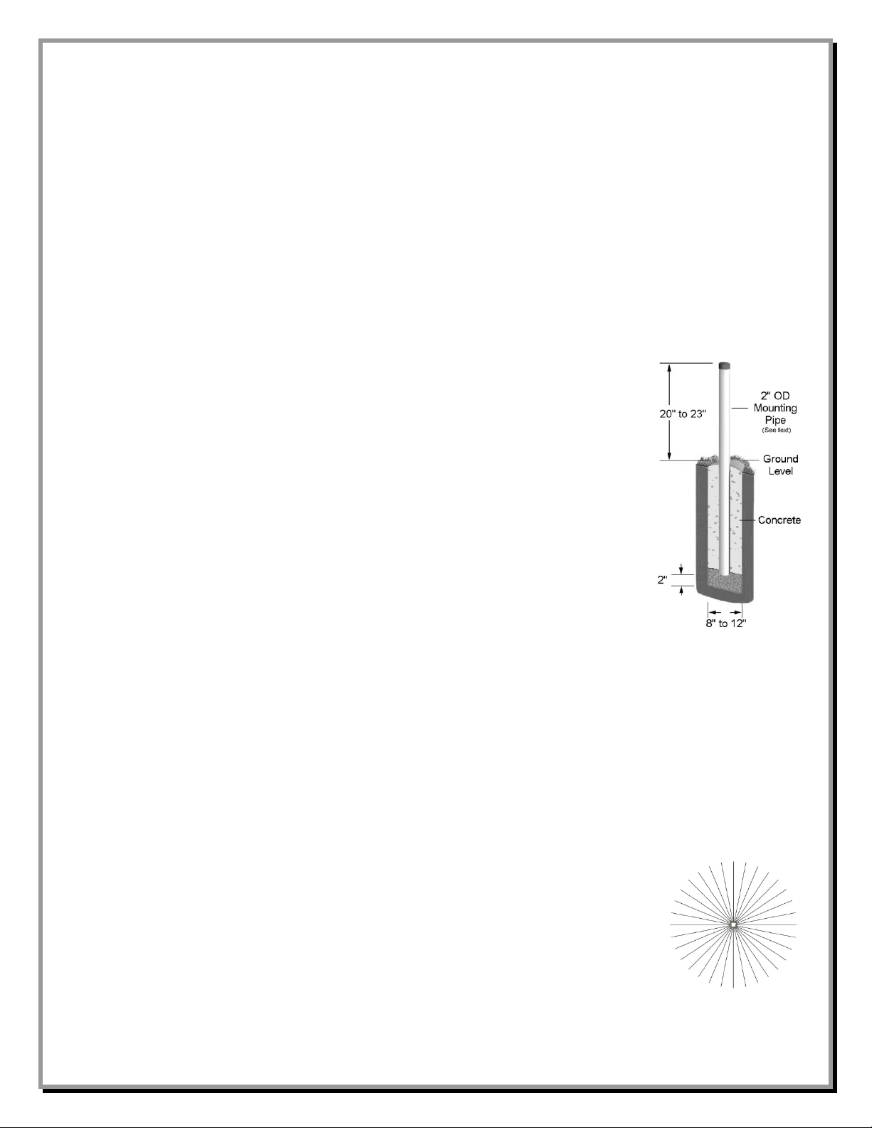
Use a customer supplied thick-walled galvanized steel mounting pipe at least 4
feet long. This will allow approximately 2 feet or more to be below ground and
approximately 2 feet above ground. A thick-walled steel pipe 1-3/4" OD to 2"
OD maximum is recommended with a minimum thickness of 1/8" (1/4"
preferred) should be used. For permanent mounting, use a post-hole digger to
make the hole deep enough to accommodate 2 feet of pipe and a couple inches
of gravel at the bottom for drainage. Set the pipe on the gravel, use the pre-mix
concrete to fill around the pipe, adding water and mixing as you fill or mix the
concrete first, then pour in the hole. Fill the hole until the concrete is level with
the ground around it. Use a level as you fill the hole to be sure the pipe is
straight. Allow to set overnight. Your location, landscape and ground conditions
may require different mounting solutions in order to have the steel mounting
pipe and the vertical antenna in a secure position.
Note: Galvanized steel, rather than aluminum, is much more suitable for mounting in concrete.
Aluminum will quickly corrode due to incompatibility with the materials used to make
concrete.
Radial System
The use of a radial system is a key requirement for a high performance quarter wave vertical
antenna system. With a vertical antenna system, the radials are the second half of the antenna. The
radials contribute to the radiation efficiency of the entire vertical antenna system.
For a ground mounted quarter-wave vertical, a minimum of 20 radials, each 20 feet long, should be
used. Using 32 radials at 20 feet long is preferred and highly recommended. The
extra radials will help overcome unknown poor-soil conditions, improve
efficiency, and ensure the best performance possible from the vertical antenna.
Improved performance will be achieved if you install 60 radials. DX Engineering
DXE-RADW Radial Wire, a stranded 14 gauge relaxed PVC insulated copper
wire is suggested for the best results. A ground mounted HF antenna should be
installed at least 20 feet from any obstructions, so all radials should fit in the
available space.
- 3 -
Page 4
The wire radials should placed as symmetrically as possible around the vertical antenna and spaced
evenly, regardless of how many radials are used. Do not cross or bunch any radial wires as this
nullifies their effectiveness. If you have limited space, put in as many straight radials as you can.
The radial wires can be attached to the vertical using the lower left V-Bolt Saddle nut. Connect the
shield of your feedline to the same V-bolt so your feedline shield is connected to the same point as
the radials. The DX Engineering DXE-RADP-3 Stainless Steel Radial Plate is an ideal optional
item which provides an excellent system for attaching radial wires to your vertical antenna system.
If an elevated mount is used, the use of four or more quarter-wave resonant radials must be attached
near the feedpoint and arranged in all directions away from the antenna.
Note: Jet-Lube SS-30 (JTL-12555) should be used between all antenna element sections. Jet
Lube SS-30 is an electrical joint compound to affect a substantial electrical connection
between metal parts such as telescoping aluminum tubing or other antenna pieces. It
ensures high conductivity at all voltage levels by displacing moisture and preventing
corrosion or oxidation. Jet-Lube should also be used on all clamps, bolts and stainless
steel threaded hardware to prevent galling and to ensure proper tightening.
Assembly
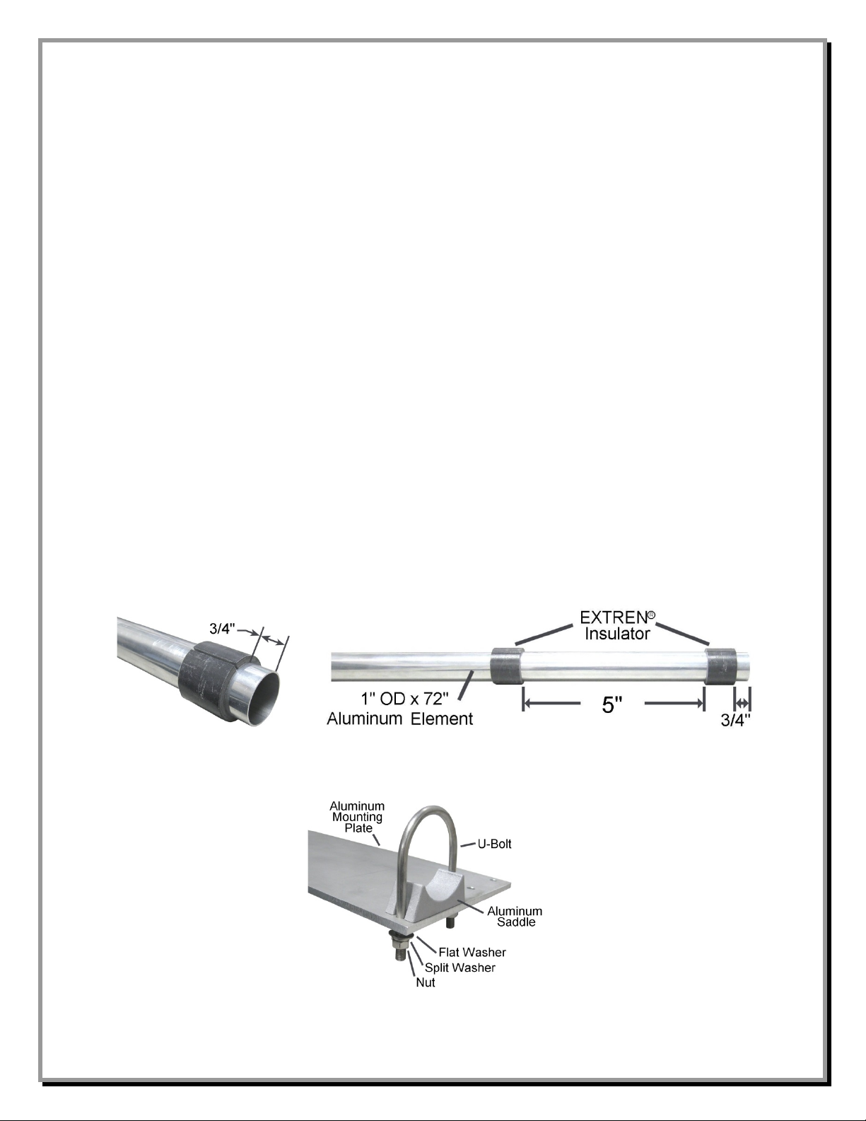
1. Slide the two EXTREN® element insulators over the bottom of the 1" OD x 72" aluminum
element (the slit in this 1" OD aluminum element goes toward the top of the antenna).
The distance from the bottom insulator to the end of the 1" OD element should be 3/4" to allow
®
room for the feedpoint which is mounted in a later step. The distance between EXTREN
element insulators is 5".
2. Assemble the Saddle Clamps loosely (on the pre-drilled aluminum plate) using the flat washers,
lock washers, nuts and U-Bolts as shown below.
- 4 -
Page 5
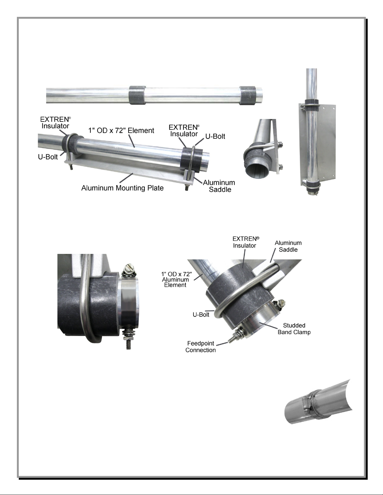
3. Slide the 1" OD element that has the EXTREN® insulators installed in the U-Bolts as shown
below. Adjust the EXTREN® insulators so they are centered on the U-Bolts. Tighten the UBolts evenly so the length of the exposed threads is approximately equal. Any U-Bolt should be
tightened evenly from side-to-side with an equal amount of thread above each nut.
4. Install the studded band clamp (antenna feedpoint) at the bottom of the 1" OD aluminum
element as shown below. Use a small amount of Penetrox A between the studded band clamp
and the 1" OD aluminum element.
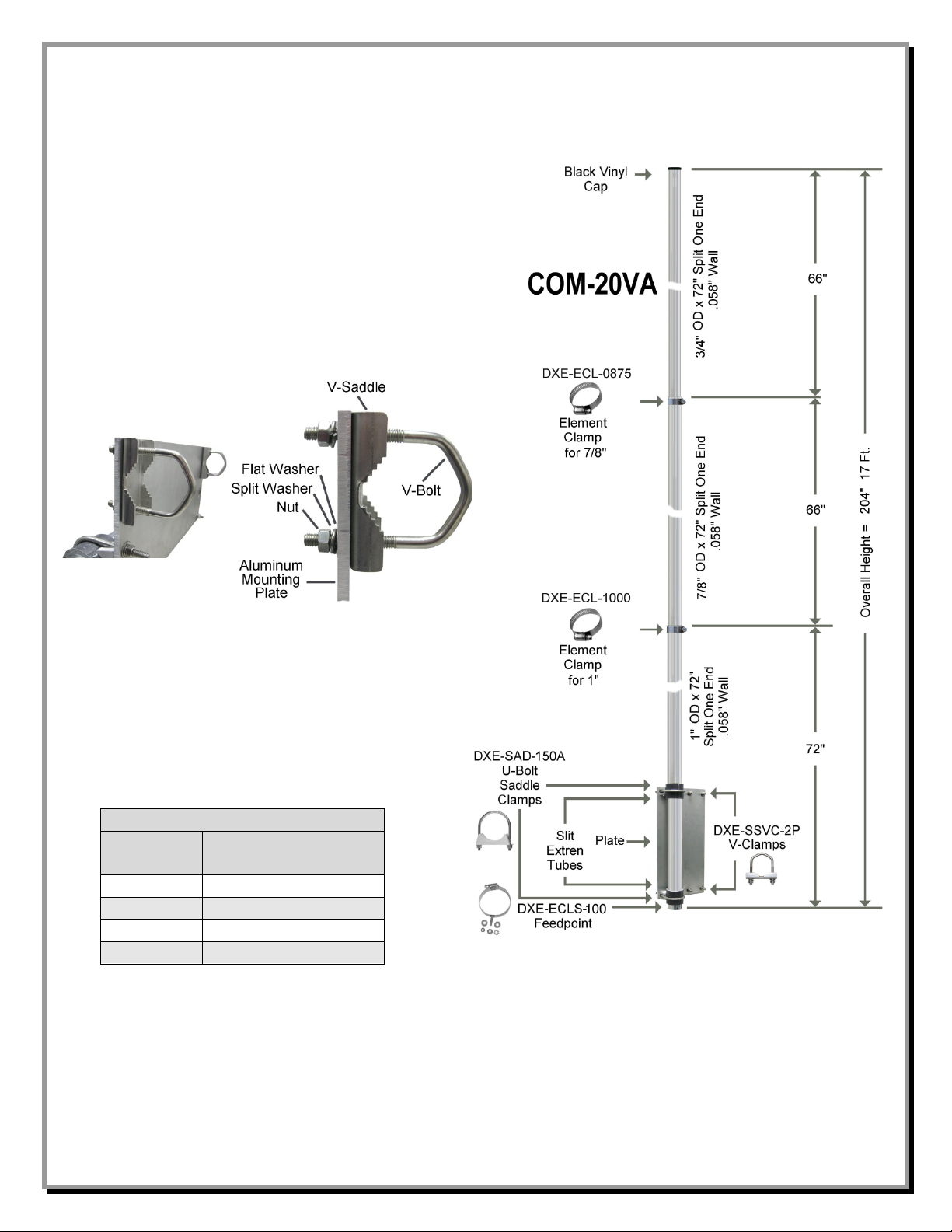
5. Assemble the vertical sections as shown in Figure 1 using the stainless steel element clamps
allowing a 6 inch overlap between the element sections. Slide all the clamps over each section
before putting them together. You can lightly tighten the clamps just
below the slits in each section to hold them until needed. Align the clamp
screws on each section to face the same direction. At final assembly, body
of the clamp should be positioned between the slits in the tubes and 1/8"
from the edge of each tube as shown to the right. When assembled as
shown you will have an overall length of 17 feet. During tuning, you will
make slight adjustments to get the center frequency to where you want it.
- 5 -
Page 6
6. Install the Black Vinyl Cap on the top
For 20 Meters
Frequency
MHz
Approximate
Overall Length
14.000
16 Feet, 8-1/2 inches
14.150
16 Feet, 6-1/2 inches
14.225
16 Feet, 5-3/8 inches
14.350
16 Feet, 3-5/8 inches
element.
7. The two stainless steel V-Bolt Clamps are
used to secure the mounting plate to the
customer supplied mounting pipe described
earlier in this manual. When the antenna is
installed on the mounting pipe, tighten the
V-Bolts evenly so the length of the exposed
threads is approximately equal. Any V-Bolt
should be tightened evenly from side-toside with an equal amount of thread above
each nut.
8. Connect the center conductor of your
coaxial feedline to the studded band clamp.
The shield from your coaxial feedline must
connect to the base plate where you connect
your radial wires.
Figure 1
COMTEK 20 Meter
Vertical Antenna
Assembled Diagram
- 6 -
Page 7
Tuning
For 20 Meters
Frequency MHz
Approximate Overall Length
14.000
16 Feet, 8-1/2 inches
14.150
16 Feet, 6-1/2 inches
14.225
16 Feet, 5-3/8 inches
14.350
16 Feet, 3-5/8 inches
For 17 meters
Frequency MHz
Approximate Overall Length
18.068
12 Feet, 11-3/8 inches
18.110
12 Feet, 11 inches
18.130
12 Feet, 10-3/4 inches
18.168
12 Feet, 10-9/16 inches
For 15 meters
Frequency MHz
Approximate Overall Length
21.000
11 Feet, 1-11/16 inches
21.150
11 Feet, 3/4 inches
21.300
11 Feet
21.450
10 Feet, 10-13/16 inches
For 12 meters
Frequency MHz
Approximate Overall Length
24.890
9 Feet, 4-13/16 inches
24.940
9 Feet, 4-9/16 inches
24.990
9 Feet, 4-5/16 inches
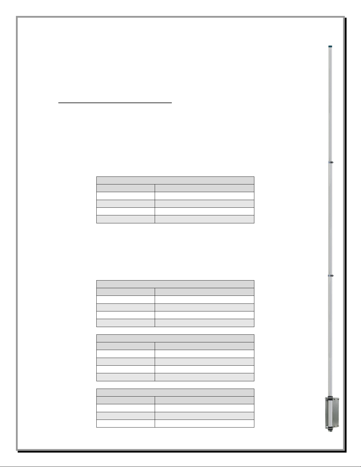
Tuning the COM-20VA 20 Meter Vertical Antenna is straightforward and intuitive. If you use an
SWR meter or an analyzer at the base of the antenna you will get the most accurate readings in a
timely fashion. Since the bandwidth of the antenna is wide the adjustment parameters are relatively
broad and fine adjustment is not usually necessary.
Note: For the purposes of these instructions the term “resonance” or “resonant frequency” is
defined as the point of lowest SWR and may be used interchangeably.
To adjust the low SWR point in the 20 meter band, merely adjust the length of the top tubing
section in the normal manner, i.e., making it longer lowers the 20 meter resonant frequency and
shortening it raises the frequency. The top element section is made moveable by loosening the
element clamp and then sliding the upper element section of the antenna either closer to the base of
the antenna or farther away depending on whether you want to lower or raise the frequency of
resonance. Be sure to tighten the clamp after making an antenna length adjustment.
The approximate lengths shown in these tables should also be used when making resonant radials
for an elevated mount antenna (feedpoint is 3 feet or higher from ground level). For ground
mounted antennas, resonant radials are not required.
When used to make a higher frequency monoband vertical, telescope the extra lengths inside of
each other.
- 7 -
Page 8
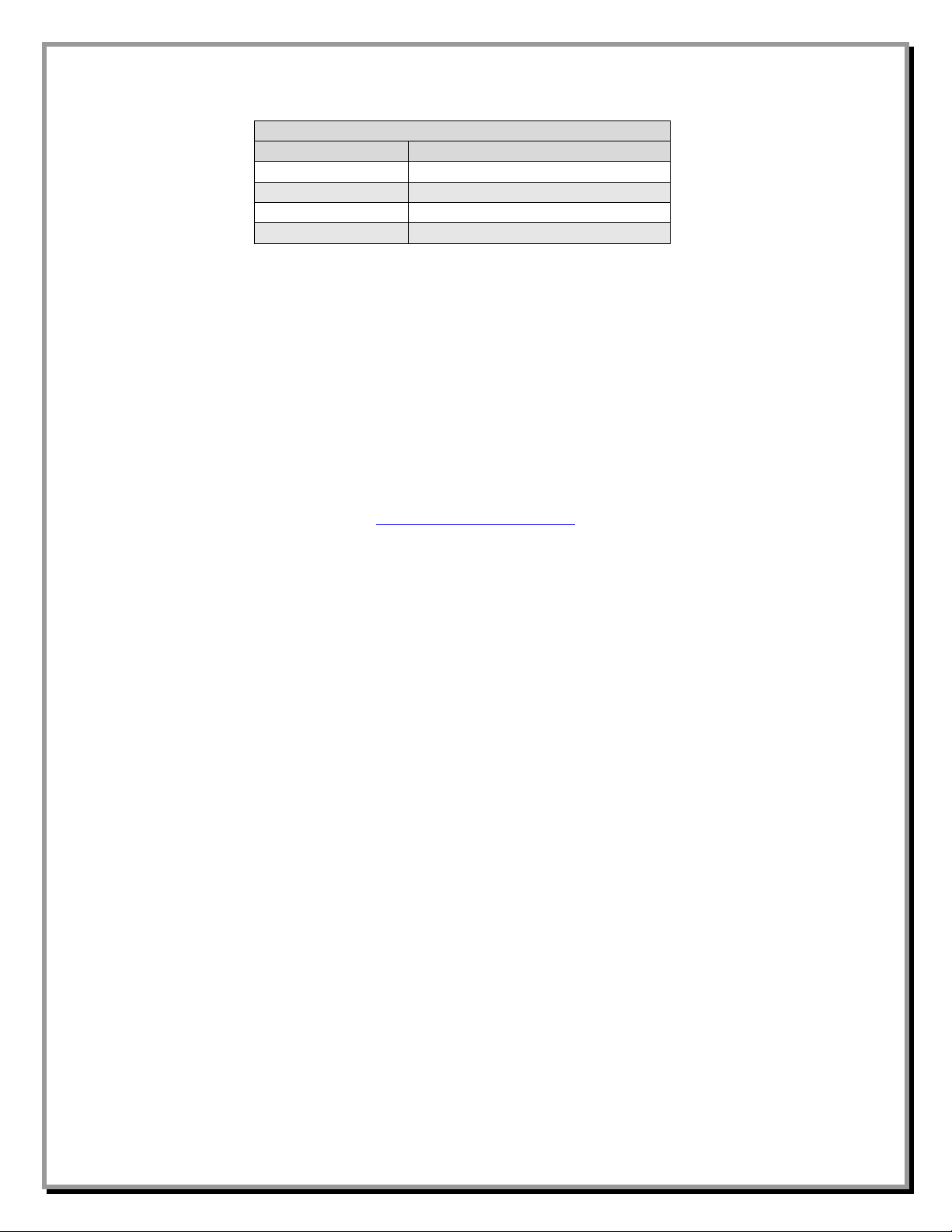
For 10 meters
Frequency MHz
Approximate Overall Length
28.000
8 Feet, 4-5/16 inches
28.250
8 Feet, 3-3/8 inches
28.450
8 Feet, 2-5/8 inches
28.700
8 Feet, 1-13/16 inches
Manual Updates
Every effort is made to supply the latest manual revision with each product. Occasionally a manual
will be updated between the time your Comtek product is shipped and when you receive it. Please
check the DX Engineering web site - Comtek product line - at (www.comteksystems.com) for the
latest revision manual.
Technical Support
If you have questions about this product, or if you experience difficulties during the installation,
contact Comtek Systems at (330) 572-3200. You can also e-mail us at:
For best service, please take a few minutes to review this manual before you call.
Warranty
All products manufactured by Comtek Systems are warranted to be free from defects in material and workmanship for a
period of one (1) year from date of shipment. Comtek Systems’ sole obligation under these warranties shall be to issue
credit, repair or replace any item or part thereof which is proved to be other than as warranted; no allowance shall be
made for any labor charges of Buyer for replacement of parts, adjustment or repairs, or any other work, unless such
charges are authorized in advance by Comtek Systems. If Comtek Systems’ products are claimed to be defective in
material or workmanship, Comtek Systems shall, upon prompt notice thereof, issue shipping instructions for return to
Comtek Systems (transportation-charges prepaid by Buyer). Every such claim for breach of these warranties shall be
deemed to be waived by Buyer unless made in writing. The above warranties shall not extend to any products or parts
thereof which have been subjected to any misuse or neglect, damaged by accident, rendered defective by reason of
improper installation, damaged from severe weather including floods, or abnormal environmental conditions such as
prolonged exposure to corrosives or power surges, or by the performance of repairs or alterations outside of our plant,
and shall not apply to any goods or parts thereof furnished by Buyer or acquired from others at Buyer’s specifications.
In addition, Comtek Systems’ warranties do not extend to other equipment and parts manufactured by others except to
the extent of the original manufacturer’s warranty to Comtek Syste ms. The obligations under the foregoing warranties
are limited to the precise terms thereof. These warranties provide exclusive remedies, expressly in lieu of all other
remedies including claims for special or consequential damages. SELLER NEITHER MAKES NOR ASSU MES ANY
OTHER WARRANTY WHATSOEVER, WHETHER EXPRESS, STATUTORY, OR IMPLIED, INCLUDING
WARRANTIES OF MERCHANTABILITY AND FITNESS, AND NO PERSON IS AUTHORIZED TO ASSUME
FOR COMTEK SYSTEMS ANY OBLIGATION OR LIABILITY NOT STRICTLY IN ACCORDANCE WITH THE
FOREGOING.
©Comtek Systems 2016
DX Engineering
Engineering Yagi Mechanical
SkyHawk™, SkyLark™, SecureMount™, OMNI-TILT™ are trademarks of PDS Electronics, Inc. No license to use or
reproduce any of these trademarks or other trademarks is given or implied. All other brands and product names are the
trademarks of their respective owners.
Specifications subject to change without notice.
®
, DXE®, DX Engineering, Inc. ®, Hot Rodz®, Maxi-Core®, DX Engineering THUNDERBOLT®, DX
®
, EZ-BUILD®, TELREX®, Gorilla Grip® Stainless Steel Boom Clamps, Butternut®,
- 8 -
 Loading...