

Comtek AT-216 Operator's Manual
AT-216 OPERATOR’S MANUAL
357 West 2700 South • Salt Lake City, Utah 84115 • Phone: (800) 496-3463 • Fax: (801) 484-6906 • http://www.comtek.com
AT-216 Wireless Auditory
Assistance Kit

Table of Contents
Section 1: General Information
1.1 Purpose of Equipment
1.2 Unit and Accessories (Supplied)
1.3 PR-216 Controls, Connectors and Indicators
1.4 M-216 Controls, Connectors and Indicators
Section 2: Operation
2.1 Operating the System
2.2 Optional EnviroMic and Smart-Mic
2.3 Connection Possibilities
2.4 Frequency Selection
2.5 Battery Removal / Replacement
2.6 Belt Clip Installation / Removal
Section 3: Battery Charger
Section 4: Frequency Chart / Frequency Groups
Section 5: Optional Accessories
Section 6: Trouble Shooting
Section 7: Care and Maintenance
Section 8: Warranty and Service
© 2006 COMTEK® All rights reserved.
Print Release Date 03-23-2006-D
Page 1
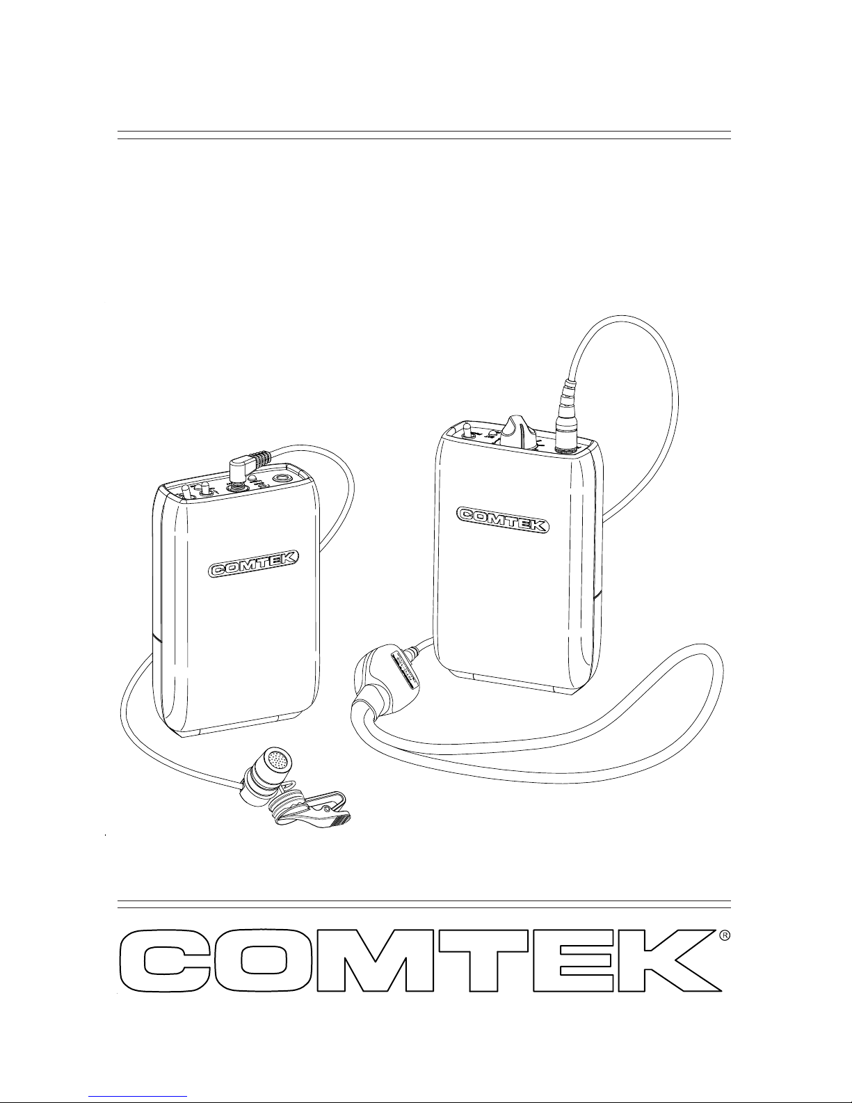
AT-216
A Close-Up On Sound
®
Digitally Synthesized
Wireless Auditory Assistance Kit

Introduction
Thank you for purchasing the COMTEK A T -216 FM wireless auditory
assistance system. For over 30 years, COMTEK FM systems have
successfully proven to be an effective way to help the hearing-impaired
individual in difficult listening situations.
The new AT-216 FM system combines the experience and integrity
of COMTEK’s preceding models with the advantages of today’s
digital technology. Plus, the all-new rugged packaging design of the
rec ei ve r an d tr an sm it ter ensures that this system will hold up to the
rigors of every day use.
This product is made in the U.S.A. with strict quality control
procedures to ensure your satisfaction. A careful reading of this
quick-reference manual will acquaint you with the characteristics
of the AT-216 system and ensur e ease of operation.
1.1 Purpose of Equipment
The AT-216 system functions as a r emote microphone for the user,
overcoming the greatest listening problems for the hearing-impaired:
• High levels of background noise
• Reverberation effects
• Distance between the speaker and listener .
The A T -216 system enables persons with impair ed hearing to comfortably
take part in activities at school, home, work, and play. In addition to a
hearing aid, the user wears the personal receiver and the neckloop
retransmit device. The PR-216 personal receiver picks up the voice of the
person wearing the M-216 transmitter , and the neckloop then retransmits
it to the hearing aid for Close-Up Sound®. If no hearing aids are used, the
receiver may also be used with headphones instead of the neckloop.
Now the person with impaired hearing has a direct link to the speaker at
greater distances for improved listening, clarity, and b ett er und erstanding.
Section 1 General Information
Page 2
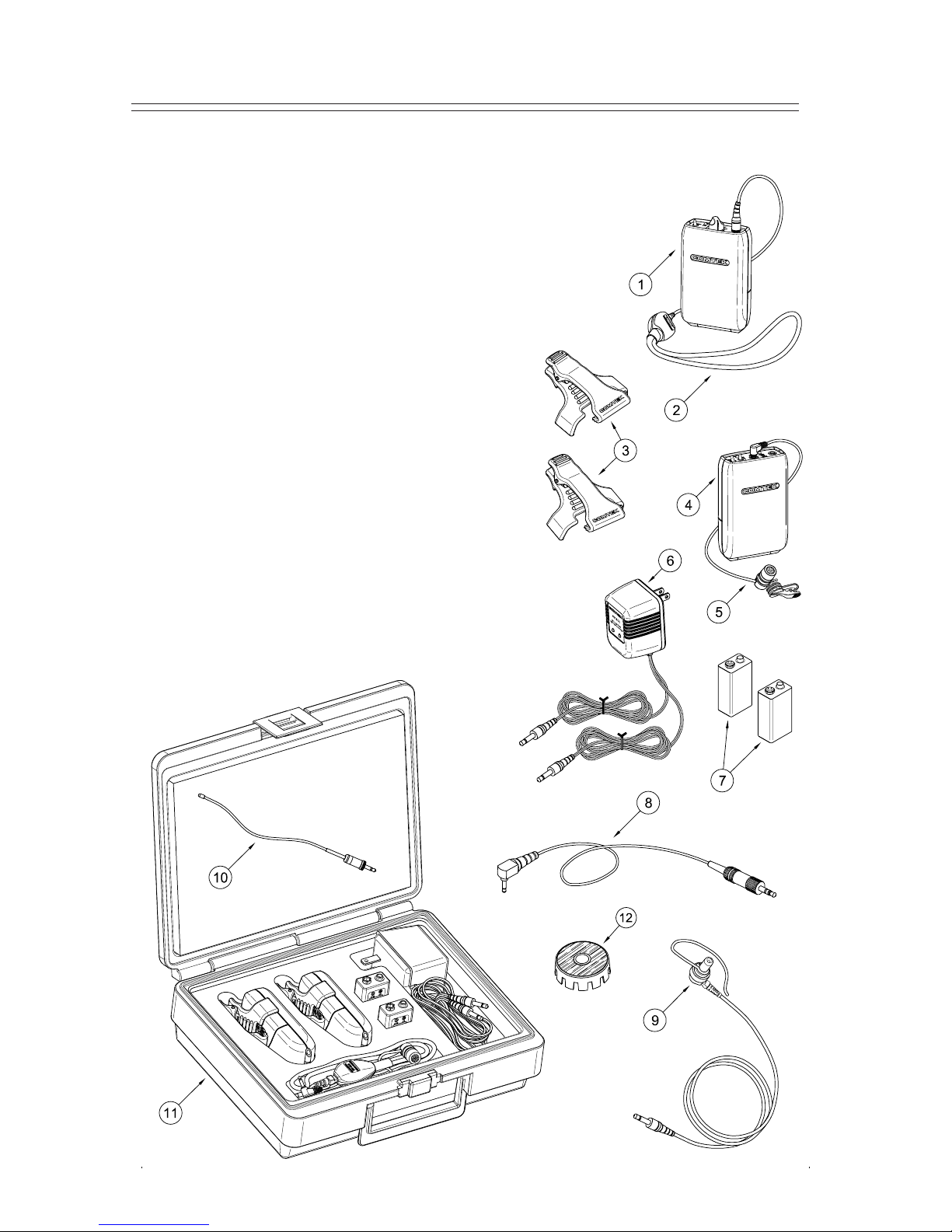
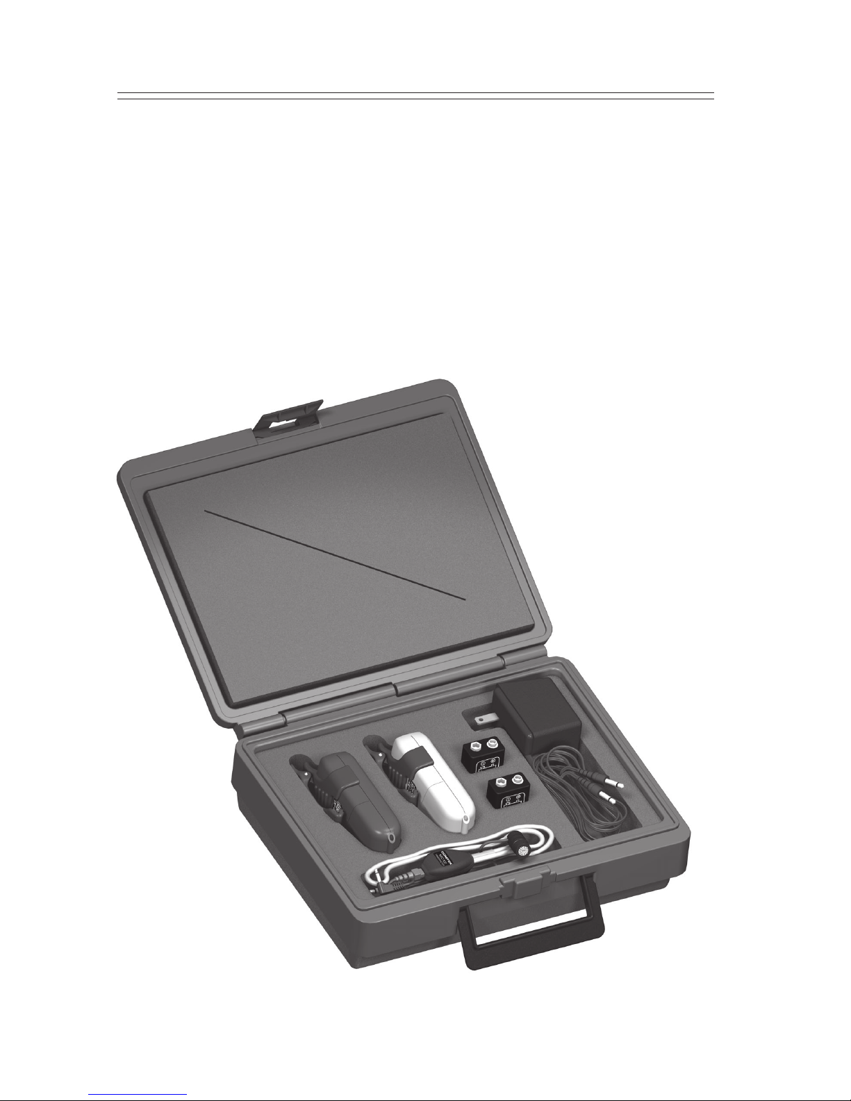
1.2 Unit and Accessories Supplied
1. Personal receiver (PR-216)
2. Neckloop transductor (NTC-102)
3. T wo belt clips (BC-216’s)
4. T ransmitter (M-216)
5. Microphone and clip (SM-183)
6. Battery charger (NBC 9-2C)
7. Rechargeable batteries (NH9-200)
8. Attenuator adaptor cord (CB-36ST)
9. Earphone assembly (SM-N)
10. Flexible specialty antenna (FWA-216)
1 1. Convenient carrying case (C-216)
12. Conference table microphone adaptor (TM-10)
Section 1 General Information (Continued)
Page 3
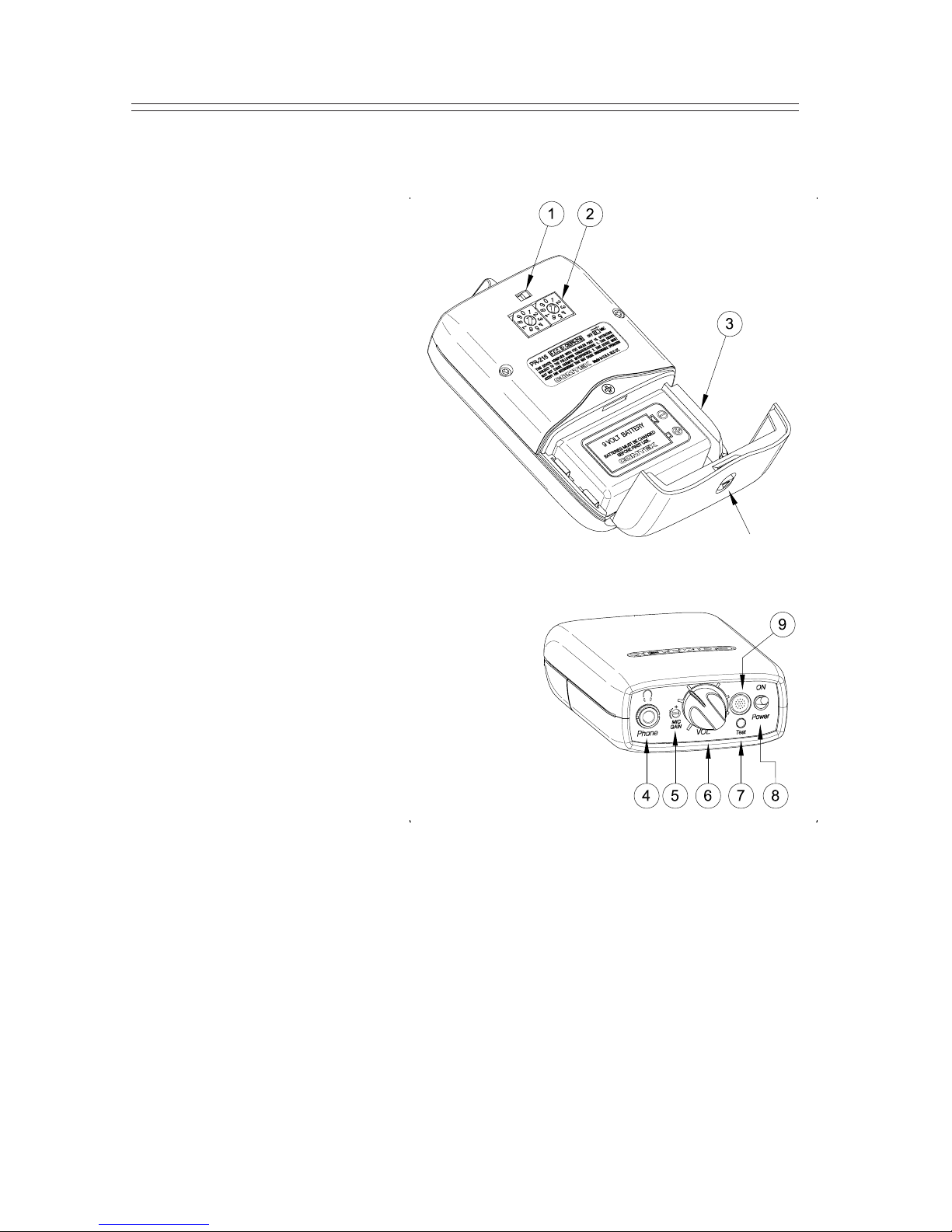
1.3 PR-216 Controls, Connectors and Indicators
Section 1 General Information (Continued)
Page 4
n
ENVIRONMENT AL MIC ON / OFF SWITCH:
This switch turns the optional EnviroMic or
Smart-Mic on and off.
(Set to right for ON and to left for OFF.)
o
CHANNEL SWITCHES: These
rotary switches are set to the same
channel as the transmitter . Actual
frequency of operation must agree
with the transmitter .
(See page 14 for frequency selection chart.)
p
BA TTER Y COMP ARTMENT : The battery
compartment features a hinged battery cover
and an alignment system that ensures proper
battery polarity. Battery installation and removal is
facilitated by simply manipulating the bottom of the
battery.
q
AUDIO OUTPUT JACK: This stereo 3.5 mm
audio output jack accommodates any 32 to 125 ohms
headphone — either stereo or mono; also, charging
of rechargeable battery with
NBC 9-2C charger.
r
EnviroMic GAIN CONTROL: (Optional)
s
VOLUME CONTROL: This control has 50 dB of range to
adjust the audio output for a comfortable listening level
(clockwise for maximum level).
t
RECEIVER ST A TUS INDICA TOR: This LED indicator will display three functions:
a. Continuous illumination ----- No signal
b. Steady slow flash -------------- Receiving signal
c. Rapid flash --------------------- Low battery
Additionally there is an audible beeping to indicate a low battery.
u
ON / OFF SWITCH: This switch turns the receiver on and off.
v
BUILT-IN ENVIRONMENT AL MIC / PLUG-IN MICROPHONE: (Optional)
(See pages 8 and 9 for details.)
Battery Cover
Latch
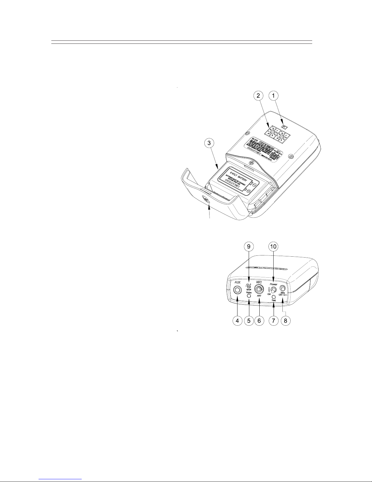
1.4 M-216 Controls, Connectors and Indicators
Section 1 General Information (Continued)
Page 5
n
COMP AND AUTO / OFF SWITCH: This switch overrides
the automatic selection of the companded channels to
non-companded operation (normally set to the right).
o
CHANNEL SWITCHES: These rotary switches
are set to the same channel as the receiver.
Actual frequency of operation must agree with
the receiver .
(See page 14 for frequency selection chart.)
p
BA TTER Y COMP ARTMENT : The
battery compartment features a hinged
battery cover and an alignment system that
ensures proper battery polarity. Battery
installation and removal is facilitated by simply
manipulating the bottom of the battery.
q
AUXILIARY AUDIO INPUT JACK:
Allows transmitter to use line level, earphone
level, or fixed AUX as an audio source; also,
charging of rechargeable battery with NBC 9-2C char ger .
r
AUDIO “VOICE” MODULA TION INDICA TOR:
This indicator is used in making adjustment with the
Audio Input Gain Control.
s
MIC / ANTENNA JACK: This jack accepts an
electret type microphone having a 36” long cord with
a micro-mini 2.5mm mono plug. This jack is also used
for the screw-in specialty antenna when the auxiliary
audio input is used.
t
POWER / BA TTER Y TEST INDICA TOR: This LED indicator will illuminate
continuously when the unit is on indicating normal operation. When the battery voltage
drops below 6 volts, the LED will flash rapidly, indicating that a new battery or charging
is needed.
u
OPTIONAL MIC MUTE SWITCH: This switch turns off the voice from the microphone
without turning off the transmitter carrier allowing the auxiliary input program to remain on.
v
AUDIO INPUT GAIN CONTROL: This is a microphone and AUX level input gain
control. This control is used with the “Voice” modulation indicator .
w
ON / OFF SWITCH: This switch turns the transmitter on and off.
Battery Cover
Latch
 Loading...