

Page 1

XSAT-7080
5 to 25, 50 & 100 Watts
X-Band Transceiver
Installation and Operation Manual
Part Number MN/XSAT7080.IOM Revision 0
Page 2

Page 3

Errata A
Comtech EFData Documentation Update
Subject:
Date:
Part Number:
Related Document:
Collating Instructions:
Comments:
The highlighted change revises the connector pinout label.
Change Specifics:
Revised Pin lable for Connector J3
February 12, 2007
MN/XSAT7080.IOM
XSAT-7080, X-Band Transceivers Installation and Operation
Manual, Rev. 0 dated October 21, 2005
Attach this errata sheet to the cover.
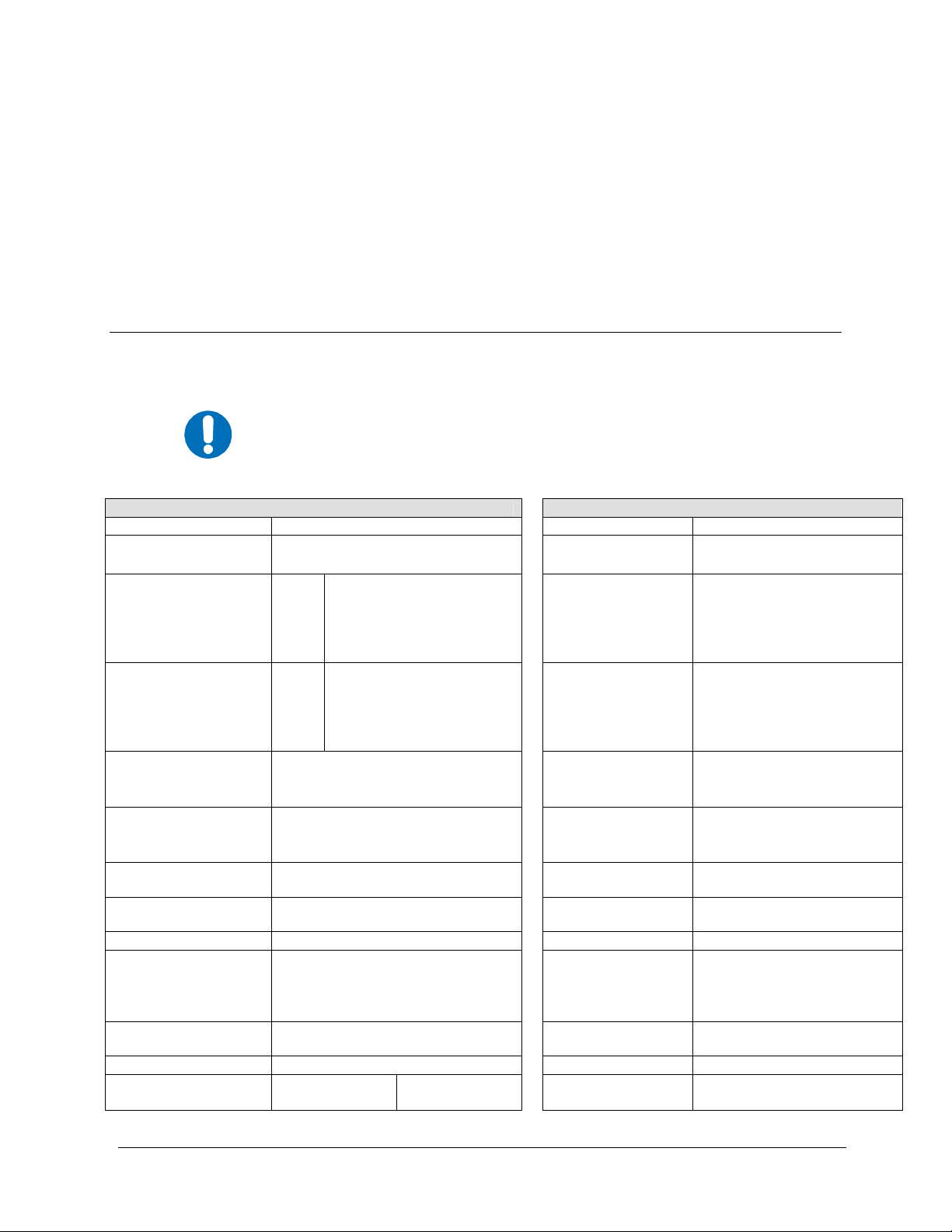
3.1.1 CONNECTOR J3: AC POWER, MAINS, 100 TO 125 VAC, OR
205
TO 240 VAC.
To avoid a serious shock hazard, correctly determine the mating
connector type in use and wire it according to the following table:
WARN ING
EARLY UNITS NEWER UNITS
Pin Mating Connector Type
A Line Ground
B Ground Neutral
Labeled
C or G
Mating Connector Type
KPT06J12-3S
MS3116J12-3S
Neutral Line
CA3106E18-22SB
Filename: T_ERRATA 1
Page 4

Filename: T_ERRATA 2
Page 5

XSAT-7080
5 to 25, 50 & 100 Watts
X-Band Transceiver
Installation and Operation Manual
Comtech EF Data is an ISO 9001
Registered Company
Part Number MN/XSAT7080.IOM
Revision 0
October 21, 2005
Copyright © Comtech EF Data, 2001. All rights reserved. Printed in the USA.
Comtech EF Data, 2114 West 7th Street, Tempe, Arizona 85281 USA, (480) 333-2200, FAX: (480) 333-2161.
Page 6

Customer Support
Contact the Comtech EF Data Customer Support Department for:
• Product support or training
• Information on upgrading or returning a product
• Reporting comments or suggestions concerning manuals
A Customer Support representative may be reached at:
Comtech EF Data
Attention: Customer Support Department
2114 West 7th Street
Tempe, Arizona 85281 USA
480 333 200 (Main Comtech EF Data Number)
480 333 4357 (Customer Support Desk)
480 333 2161 FAX
or, E-Mail can be sent to the Customer Support Department at:
service@comtechefdata.com
Contact us via the web at www.comtechefdata.com
1. To return a Comtech EF Data product (in-warranty and out-of-warranty) for
repair or replacement:
2. Request a Return Material Authorization (RMA) number from the Comtech EF
Data Customer Support Department.
3. Be prepared to supply the Customer Support representative with the model
number, serial number, and a description of the problem.
4. To ensure that the product is not damaged during shipping, pack the product in
its original shipping carton/packaging.
5. Ship the product back to Comtech EF Data. (Shipping charges should be
prepaid.)
For more information regarding the warranty policies, see Warranty Policy, p. xiii.
.
ii
Page 7

Table of Contents
CHAPTER 1. INTRODUCTION.......................................................................................................... 1–1
1.1
Introduction ................................................................................................................................................1–1
1.2 Functional Description...............................................................................................................................1–1
CHAPTER 2. SPECIFICATION..........................................................................................................2–1
2.1
Specifications ..............................................................................................................................................2–1
2.2 Dimension Envelope ...................................................................................................................................2–2
CHAPTER 3. SYSTEM OPERATION ................................................................................................ 3–1
3.1
Pin-Outs.......................................................................................................................................................3–1
3.1.1
Connector J3 ............................................................................................................................................3–1
3.1.2 Connector J5 ............................................................................................................................................3–2
3.2 Turning on the XSAT.................................................................................................................................3–3
3.3
Configuring the XSAT ...............................................................................................................................3–3
3.3.1
Frequency.................................................................................................................................................3–3
3.3.2 Attentuation..............................................................................................................................................3–3
3.3.3 Gain Offset...............................................................................................................................................3–4
3.3.4 Mute Mode...............................................................................................................................................3–4
3.3.5 Mute .........................................................................................................................................................3–4
3.3.6 TX Amplifier............................................................................................................................................3–5
3.3.7 Channel Slope Adjust Mode ....................................................................................................................3–5
3.3.8 Channel Slope Adjust...............................................................................................................................3–5
3.3.9 Reference Frequency Adjust....................................................................................................................3–6
3.3.10 External Reference Fault Logic................................................................................................................3–6
3.3.11 Cold Start Function ..................................................................................................................................3–6
3.3.12 Auto Fault Recovery ................................................................................................................................3–6
3.3.13 LNA Current Source ................................................................................................................................3–7
3.3.14
LNA Current Calibrating and Current Window.......................................................................................3–7
iii
Page 8

XSAT7080 X-Band Transceiver Revision 0
Preface MN/XSAT7080.IOM
3.3.15 LNA Fault Logic......................................................................................................................................3–8
3.3.16 Redundancy Controller Auto/Manual ......................................................................................................3–8
3.3.17 Redundancy Controller Toggle ................................................................................................................3–8
3.3.18 Set Physical Address................................................................................................................................3–9
3.3.19 Set Baud Rate...........................................................................................................................................3–9
3.3.20 Set Date....................................................................................................................................................3–9
3.3.21 Set Time ...................................................................................................................................................3–9
CHAPTER 4. REMOTE CONTROL ................................................................................................... 4–1
4.1
Introduction ................................................................................................................................................4–1
4.1.1 RS-485 .....................................................................................................................................................4–1
4.1.2 RS-232 .....................................................................................................................................................4–2
4.2 Basic Protocol .............................................................................................................................................4–2
4.2.1 Packet Structure .......................................................................................................................................4–3
4.2.1.1 Start Of Packet.................................................................................................................................4–4
4.2.1.2 Address............................................................................................................................................4–4
4.2.1.3 Instruction Code ..............................................................................................................................4–4
4.2.1.4 Instruction Code Qualifier...............................................................................................................4–4
4.2.1.5 Message Arguments ........................................................................................................................4–6
4.2.1.6 End Of Packet..................................................................................................................................4–6
Commands or Responses ...........................................................................................................................4–6
4.3
CHAPTER 5. REDUNDANT SYSTEMS ............................................................................................5–1
5.1
Redundant System......................................................................................................................................5–1
5.2 RSU-5060 Interfaces...................................................................................................................................5–3
5.2.1 Electrical Interface ...................................................................................................................................5–3
5.2.1.1 XSAT Unit A Interface, J1..............................................................................................................5–4
5.2.1.2 Rx Waveguide Switch interface, J2.................................................................................................5–4
5.2.1.3 XSAT Unit B Interface, J3 ..............................................................................................................5–5
5.2.1.4 Tx Waveguide Switch interface, J4.................................................................................................5–5
5.2.1.5 M&C Interface, J5...........................................................................................................................5–6
5.2.1.6 Tx IF Interfaces, J6 – J8 ..................................................................................................................5–6
5.2.1.7 RF IF Interfaces, J9 - J11 ................................................................................................................5–7
5.2.2 Mechanical Interface................................................................................................................................5–7
5.3 RSU-5060 Operation ..................................................................................................................................5–8
5.3.1 RS-485 Interface ......................................................................................................................................5–9
5.3.2 RED AUTO/MANUAL signal.................................................................................................................5–9
5.3.3 SWITCH CMD signal............................................................................................................................5–10
5.3.4 REDUNDANCY A/B signals................................................................................................................5–10
5.3.5 REDUND_FLT signal ...........................................................................................................................5–10
5.3.6 AUXCOM signals..................................................................................................................................5–10
5.4 Configuring A Redundant System ..........................................................................................................5–11
iv
Page 9

XSAT7080 X-Band Transceiver Revision 0
Preface MN/XSAT7080.IOM
CHAPTER 6. THEORY OF OPERATION.......................................................................................... 6–1
6.1
RF Signal Conversion.................................................................................................................................6–2
6.1.1 Downconverter.........................................................................................................................................6–2
6.1.2 Upconverter..............................................................................................................................................6–3
6.2 Monitor & Control..................................................................................................................................6–4
CHAPTER 7. MAINTENANCE AND TROUBLESHOOTING ............................................................ 7–1
7.1
Maintenance Testing ..................................................................................................................................7–2
7.2 Troubleshooting..........................................................................................................................................7–2
7.3 Converter Faults.........................................................................................................................................7–2
7.3.1 DC Power Supply Voltages......................................................................................................................7–2
7.3.2 RF Converter Module ..............................................................................................................................7–3
7.3.3 Reference Oscillator Module ...................................................................................................................7–3
7.3.4 LNA Current Fault...................................................................................................................................7–3
7.3.5 Fan Fault ..................................................................................................................................................7–4
7.3.6 Temperature Fault....................................................................................................................................7–4
7.4 Equipment Return and Repair Procedure ...............................................................................................7–4
7.5 Product Application, Upgrading or Training Information.....................................................................7–4
CHAPTER 8. XSAT-7080 10 WATT UNIT......................................................................................... 8–1
8.1
Overview......................................................................................................................................................8–1
8.1.1
Function Description................................................................................................................................8–2
8.1.2 Prime Power Level...................................................................................................................................8–2
8.1.3 Physical Dimensions................................................................................................................................8–2
8.2 Specifications ..............................................................................................................................................8–3
CHAPTER 9. EXTERNAL AMPLIFIER COMMUNICATION............................................................. 9–1
9.1
Overview......................................................................................................................................................9–1
9.2 External Amplifier Communication .........................................................................................................9–1
v
Page 10

XSAT7080 X-Band Transceiver Revision 0
Preface MN/XSAT7080.IOM
APPENDIX A. 5 - 25 WATT INSTALLATION .................................................................................... A–1
A.1
Unpacking and Inspection ........................................................................................................................A–1
A.2
Personnel ....................................................................................................................................................A–1
A.3 Tools Required...........................................................................................................................................A–1
A.4 Single-Thread Configuration....................................................................................................................A–2
A.4.1
Mounting Kit........................................................................................................................................... A–5
A.4.2 Single-Thread Installation.......................................................................................................................A–5
A.4.3 LNA Installation .....................................................................................................................................A–8
A.4.4 Cable Installation ....................................................................................................................................A–9
A.5 Redundancy Configuration ....................................................................................................................A–11
A.5.1
Mounting Kit......................................................................................................................................... A–12
A.5.2 Assemble TX/Remote Switch...............................................................................................................A–18
A.5.3 Connect Cabling to the Remote Switch Box ........................................................................................ A-19
A.5.4
Redundancy Installation........................................................................................................................A–20
A.5.5 LNA Installation ...................................................................................................................................A–23
A.5.6 Cable Installation ..................................................................................................................................A–25
A.6 SPAR Mounting.......................................................................................................................................A–27
A.6.1
SPAR Mounting Kit..............................................................................................................................A–27
A.6.2 Mounting Kits .......................................................................................................................................A–28
A.6.3 Mounting Instructions .......................................................................................................................... A-28
APPENDIX B. 50 AND 100 WATT INSTALLATION.......................................................................... B–1
Unpacking and Inspection ........................................................................................................................ B–1
B.1
B.2
Personnel.................................................................................................................................................... B–2
B.3 Tools Required........................................................................................................................................... B–2
B.4 Single-Thread Configuration....................................................................................................................B–3
B.4.1
Mounting Kit ........................................................................................................................................... B–3
B.4.2 Single-Thread Installation .......................................................................................................................B–6
B.4.3 LNA Installation ..................................................................................................................................... B–9
B.4.4 Cable Installation .................................................................................................................................. B–10
B.5 Redundancy Configuration ....................................................................................................................B–11
B.5.1
Mounting Kit ......................................................................................................................................... B–11
B.5.2 Redundancy Installation........................................................................................................................ B–19
B.5.3 LNA Installation ................................................................................................................................... B–26
B.5.4 Cable Installation .................................................................................................................................. B–27
vi
Page 11

XSAT7080 X-Band Transceiver Revision 0
Preface MN/XSAT7080.IOM
Figures
Figure 1-1. XSAT-7080 Dimensional Drawing.........................................................................................................1–3
Figure 5-1. Typical XSAT Redundancy System, without IF Transfer Switches.......................................................5–1
Figure 5-2. Typical XSAT Redundancy System, with IF TRansfer Switches...........................................................5–2
Figure 5-3. Mechanical Dimensions and Mounting Interface ..................................................................................5–7
Figure 5-4. RSU-5060 Functional Block Diagram....................................................................................................5–8
Figure 6-1. Functional Block Diagram of the Downconverter Section .....................................................................6–2
Figure 6-2. Functional Block Diagram of the Upconverter Section ..........................................................................6–3
Figure 7-1. Converter Signal and Interconnecting Cable Diagram............................................................................7–1
Figure 9-1. Connector for External Amplifier Communication................................................................................B–2
Figure A-1. Universal Pole Mounting Kit, AS/0414................................................................................................A–3
Figure A-2. Single-Thread Bracket, AS/0608 ..........................................................................................................A–4
Figure A-3. Single-Thread Installation.....................................................................................................................A–5
Figure A-4. Preparing the Pole Bracket....................................................................................................................A–5
Figure A-5. Installing the Pole Bracket with XSAT Mounting Plate .......................................................................A–6
Figure A-5b. On the Pole..........................................................................................................................................A–6
Figure A-5c. Looking Down.....................................................................................................................................A–6
Figure A-6. XSAT Single-Thread Bracket with Hardware ......................................................................................A–7
Figure A-7. Install XSAT Single-Thread Bracket ....................................................................................................A–7
Figure A-8. Mount XSAT Unit ................................................................................................................................A–8
Figure A-9. Cable Connections ..............................................................................................................................A–10
Figure A-10. Redundancy Configuration ...............................................................................................................A–11
Figure A-11. 1:1 25W XSAT TX Switch Bracket, AS/0489..................................................................................A–13
Figure A-12. Cable Kit, AS/0440...........................................................................................................................A–15
Figure A-13. Kit, Waveguide, AS/9512 .................................................................................................................A–16
Figure A-14. Assembly, TX/Remote Switch, AS/0490..........................................................................................A–17
Figure A-15. TX/Remote Switch Assembly, AS/0503...........................................................................................A–18
Figure A-16. Connections for the TX/Remote Switch Ports ..................................................................................A–18
Figure A-17. Remote Switch Cast Box ..................................................................................................................A–19
Figure A-17a. Switch Box with Cables ..................................................................................................................A–19
Figure A-18. Installation of the Redundant Brackets .............................................................................................A–20
Figure A-19. Installation of the XSAT Transceivers..............................................................................................A–21
Figure A-20. Redundant Configuration with Cables Installed................................................................................A–22
Figure A-21. Switch Port Locations .......................................................................................................................A–23
Figure A-22. LNA Switch Kit ................................................................................................................................A–23
Figure A-23. Cabling the Redundant Configuration (Block Diagram)...................................................................A–26
Figure A-24. SPAR Mount, 1 x 2, AS/0422...........................................................................................................A–27
Figure B-1. Universal Pole Mounting Kit, AS/0414 ................................................................................................ B–4
Figure B-2. Mounting Brackets, AS/0415................................................................................................................ B–5
Figure B-3. Preparing the Pole Bracket.................................................................................................................... B–6
Figure B-4. Looking Down.......................................................................................................................................B–7
Figure B-5. Installing the Pole Bracket ....................................................................................................................B–7
Figure B-6. Single-Thread Bracket with Hardware.................................................................................................. B–7
Figure B-7. Install XSAT Single-Thread Bracket ....................................................................................................B–7
Figure B-8. Install XSAT 100 Watt Unit.................................................................................................................. B–8
Figure B-9. Installation of LNA ............................................................................................................................... B–9
Figure B-10. Cable Connection .............................................................................................................................. B–11
Figure B-11. TX Switch Mount Kit, AS/0479 (Partial Assembly)......................................................................... B–13
Figure B-12. LNA Mounting Plate Assembly, AS/9751-1..................................................................................... B–14
Figure B-13. Cable Kit, AS/0440 ...........................................................................................................................B–15
vii
Page 12

XSAT7080 X-Band Transceiver Revision 0
Preface MN/XSAT7080.IOM
Figure B-14. Waveguide Kit, CPR112, AS/9512-2................................................................................................ B–16
Figure B-15. Waveguide Switch, TX 1:1, AS/9759-1 (Partial Kit)........................................................................ B–17
Figure B-16. Remote Switch Box Assembly, AS/0490.......................................................................................... B–18
Figure B-17. Redundant Configuration .................................................................................................................. B–19
Figure B-18. Assemble Waveguide Switch, AS/9759-1 (Partial Kit) .................................................................... B–20
Figure B-19. Switch Port Locations ....................................................................................................................... B–20
Figure B-20. Preparing the Pole Bracket................................................................................................................ B–21
Figure B-21. Pipe Blocks........................................................................................................................................B–22
Figure B-22. Looking Down at Pipe Blocks...........................................................................................................B–22
Figure B-23. Instalation of the Waveguide Switch................................................................................................. B–24
Figure B-24. Waveguide Layout ............................................................................................................................B–24
Figure B-25. LNA Switch Kit, AS/9751-1............................................................................................................. B–25
Figure B-26. Cable Installation...............................................................................................................................B–26
viii
Page 13

XSAT7080 X-Band Transceiver Revision 0
Preface MN/XSAT7080.IOM
Tables
Table 4-1. EIA-485 Interface.....................................................................................................................................4–1
Table 4-2. EIA-232 Interface.....................................................................................................................................4–2
Table 4-3. Master-to-Slave ........................................................................................................................................4–3
Table 4-4. Slave-to-Master ........................................................................................................................................4–3
Table 5-1. RSU-5060 Interface Connectors, Without IF Transfer Switches .............................................................5–2
Table 5-2. RSU-5060 Interface Connectors, with IF Transfer Switches ...................................................................5–3
Table 5-3. XSAT A Signal Description (Connector J1)............................................................................................5–4
Table 5-4. RX Waveguide Switch Signal Description (Connector J2)......................................................................5–4
Table 5-5. XSAT B Signal Description (Connector J3) ............................................................................................5–5
Table 5-6. TX Waveguide Switch Signal Description (Connector J4)......................................................................5–5
Table 5-7. M&C Signal Signal Description (Connector J5)......................................................................................5–6
Table A-1. Universal Pole Mount, AS/0599.............................................................................................................A–2
Table A-2. Universal Pole Mount, AS/0414.............................................................................................................A–3
Table A-3. XSAT Mounting Brackets, AS/0608......................................................................................................A–4
Table A-4. 1:1 Mounting Kit ASsembly, AS/0596 ................................................................................................A–12
Table A-5. Assembly, 1:125W XSAT Switch Bracket, AS/0489:.........................................................................A–13
Table A-6. Assembly, 1:1 25W XSAT, AS0510....................................................................................................A–14
Table A-7. LNA Mounting Kit, Typical.................................................................................................................A–14
Table A-8. Kit, Cable - 1:1 X-Band, AS/0440 .......................................................................................................A–15
Table A-9. Kit, Waveguide, AS/9512-1 .................................................................................................................A–16
Table A-10. Assembly, Remote Switch Box, AS/0490..........................................................................................A–17
Table A-11. TX/Remote Switch Assembly, AS/0503............................................................................................A–18
Table A-12. SPAR Mounting Kit, AS/0422...........................................................................................................A–27
Table B-1. Universal Pole Mount, AS/0600............................................................................................................. B–3
Table B-2. Final 1:1 X-Band LNA Assembly, KT/9850........................................................................................ B–12
Table B-3. 1:1 Mounting Assembly, KT/9849....................................................................................................... B–12
ix
Page 14

XSAT7080 X-Band Transceiver Revision 0
Preface MN/XSAT7080.IOM
Notes:
________________________________________________________________________
________________________________________________________________________
________________________________________________________________________
________________________________________________________________________
________________________________________________________________________
________________________________________________________________________
________________________________________________________________________
________________________________________________________________________
________________________________________________________________________
________________________________________________________________________
________________________________________________________________________
________________________________________________________________________
________________________________________________________________________
________________________________________________________________________
________________________________________________________________________
________________________________________________________________________
________________________________________________________________________
________________________________________________________________________
________________________________________________________________________
________________________________________________________________________
________________________________________________________________________
________________________________________________________________________
________________________________________________________________________
________________________________________________________________________
________________________________________________________________________
________________________________________________________________________
________________________________________________________________________
________________________________________________________________________
________________________________________________________________________
________________________________________________________________________
________________________________________________________________________
________________________________________________________________________
________________________________________________________________________
________________________________________________________________________
________________________________________________________________________
________________________________________________________________________
________________________________________________________________________
________________________________________________________________________
________________________________________________________________________
________________________________________________________________________
________________________________________________________________________
________________________________________________________________________
x
Page 15
XSAT7080 X-Band Transceiver Revision 0
Preface MN/XSAT7080.IOM
About this Manual
This manual provides installation and operation information for the Comtech EF Data XSAT7080 X-Band Transceiver, 5 to 25, 50, and 100-WATT. This is a technical document intended for
earth station engineers, technicians, and operators responsible for the operation and maintenance
of the XSAT-7080 X-Band Transceiver.
Conventions and References
Cautions and Warnings
CAUTION indicates a hazardous situation that, if not avoided, may result in
minor or moderate injury. CAUTION may also be used to indicate other
CAUTION
WARN ING
unsafe practices or risks of property damage.
WARNING indicates a potentially hazardous situation that, if not avoided,
could result in death or serious injury.
IMPORTANT indicates a statement that is associated with the task
IMPORTANT
being performed.
Metric Conversion
Metric conversion information is located on the inside back cover of this manual. This
information is provided to assist the operator in cross-referencing English to Metric conversions.
Trademarks
Windows is a trademark of the Microsoft Corporation.
Other product names mentioned in this manual may be trademarks or registered trademarks of
their respective companies and are hereby acknowledged.
Reporting Comments or Suggestions Concerning this Manual
Comments and suggestions regarding the content and design of this manual will be appreciated.
To submit comments, please contact the Comtech EF Data Technical Publication department:
techpubs@comtechefdata.com
xi
Page 16

XSAT7080 X-Band Transceiver Revision 0
Preface MN/XSAT7080.IOM
Safety Notice
This equipment has been designed to minimize exposure of personnel to hazards.
The operators and technicians must:
• Know how to work around, with and on high voltage equipment.
• Exercise every precaution to ensure personnel safety.
• Exercise extreme care when working near high voltages.
• Be familiar with the warnings presented in this manual.
CAUTION - A Neutral Fusing - Double pole/ neutral fusing used on the
prime power supply input.
CAUTION
Installation Guidelines Regarding Power Line Quality
As a company with many years of experience selling and servicing equipment installed around
the world, Comtech EF Data has become familiar with the varying quality of the AC power grid
around the world. The following offers some installation guidelines that should help ensure a
reliable installation.
• Surge suppression: High voltage surges can cause failure of the power supply.
These surges are typically caused by circuit switching on the main AC power grid,
erratic generator operation, and by lightning strikes. While the transceiver does have
built in surge suppression, if the unit will be installed in a location with questionable
power grid quality, Comtech EF Data recommends installation of additional power
conditioning/surge suppression at the power junction box.
• Grounding: The transceiver provides a grounding terminal. This is provided to allow
the user to ground the transceiver to the antenna’s grounding network. All
components installed at the antenna should be grounded to a common grounding
point at the antenna.
• Electrical welding: If welding needs to take place at the antenna, disconnect all
cables from the transceiver except for the ground wire. Cap all RF connections with
terminations. This will prevent damage to the input/output circuitry of the
transceiver.
• Lightning: Lightning strikes on or around the antenna will generate extremely high
voltages on all cables connected to the transceiver. Depending on the severity of the
strike, the transceivers internal surge protection combined with the recommended
external suppression may protect the transceivers power supply. However, if the
installation will be in an area with a high probability of lightning strikes, Comtech EF
Data recommends the installation of surge suppression on the RF and IF cables. One
source of these suppressors is PolyPhaser (www.polyphaser.com
For further information, please contact Comtech EF Data, Customer Support Department.
)
xii
Page 17

XSAT7080 X-Band Transceiver Revision 0
Preface MN/XSAT7080.IOM
Warranty Policy
This Comtech EF Data product is warranted against defects in material and workmanship for a
period of 2 years from the date of shipment. During the warranty period, Comtech EF Data will,
at its option, repair or replace products that prove to be defective.
For equipment under warranty, the customer is responsible for freight to Comtech EF Data and all
related custom, taxes, tariffs, insurance, etc. Comtech EF Data is responsible for the freight
charges only for return of the equipment from the factory to the customer. Comtech EF Data will
return the equipment by the same method (i.e., Air, Express, Surface) as the equipment was sent
to Comtech EF Data.
Limitations of Warranty
The foregoing warranty shall not apply to defects resulting from improper installation or
maintenance, abuse, unauthorized modification, or operation outside of environmental
specifications for the product, or, for damages that occur due to improper repackaging of
equipment for return to Comtech EF Data.
No other warranty is expressed or implied. Comtech EF Data specifically disclaims the implied
warranties of merchantability and fitness for particular purpose.
Exclusive Remedies
The remedies provided herein are the buyer's sole and exclusive remedies. Comtech EF Data shall
not be liable for any direct, indirect, special, incidental, or consequential damages, whether based
on contract, tort, or any other legal theory.
Disclaimer
Comtech EF Data has reviewed this manual thoroughly in order that it will be an easy-to-use
guide to your equipment. All statements, technical information, and recommendations in this
manual and in any guides or related documents are believed reliable, but the accuracy and
completeness thereof are not guaranteed or warranted, and they are not intended to be, nor should
they be understood to be, representations or warranties concerning the products described.
Further, Comtech EF Data reserves the right to make changes in the specifications of the products
described in this manual at any time without notice and without obligation to notify any person of
such changes.
If you have any questions regarding your equipment or the information in this manual, please
contact the Comtech EF Data Customer Support Department.
xiii
Page 18

XSAT7080 X-Band Transceiver Revision 0
Preface MN/XSAT7080.IOM
Notes:
________________________________________________________________________
________________________________________________________________________
________________________________________________________________________
________________________________________________________________________
________________________________________________________________________
________________________________________________________________________
________________________________________________________________________
________________________________________________________________________
________________________________________________________________________
________________________________________________________________________
________________________________________________________________________
________________________________________________________________________
________________________________________________________________________
________________________________________________________________________
________________________________________________________________________
________________________________________________________________________
________________________________________________________________________
________________________________________________________________________
________________________________________________________________________
________________________________________________________________________
________________________________________________________________________
________________________________________________________________________
________________________________________________________________________
________________________________________________________________________
________________________________________________________________________
________________________________________________________________________
________________________________________________________________________
________________________________________________________________________
________________________________________________________________________
________________________________________________________________________
________________________________________________________________________
________________________________________________________________________
________________________________________________________________________
________________________________________________________________________
________________________________________________________________________
________________________________________________________________________
________________________________________________________________________
________________________________________________________________________
________________________________________________________________________
________________________________________________________________________
________________________________________________________________________
________________________________________________________________________
________________________________________________________________________
________________________________________________________________________
________________________________________________________________________
xiv
Page 19

Chapter 1. INTRODUCTION
1.1 INTRODUCTION
This manual provides instructions on the installation, operation and maintenance of the
XSAT-7080, 5 to 25, 50, and 100 Watt Model X-Band Transceiver, manufactured by
Comtech EF Data, Tempe, Arizona.
1.2 Functional Description
The XSAT70870 is designed for use in communication systems, or in satellite up-link
data systems, for the reception of SCPC/MCPC, DAMA, and TDMA communication
signals. It can also be used in communications system applications with full transponder
HDTV and analog TV.
The converter is environmentally sealed and is designed to be hard mounted on or near
the antenna structure. A covered cooling fan is mounted on the outside of the unit to
maintain a reduced operating temperature for enhanced reliability.
The Downconverter RF input connector is wired to supply DC voltage to an LNA.
This voltage is capable of damaging any test equipment connected to the
WARN ING
connector. Do not connect test equipment to this connector without a coaxial DC
block between the connector and the test equipment.
-
- 1–1
Page 20

XSAT7080 X-Band Transceiver Revision 0
r
r
Introduction MN/XSAT7080.IOM
XSAT-7080
X-Band Transceive
5 to 25 Watt
XSAT-7080
50 Watt
X-Band Transceiver
XSAT-7080
100 Watt
X-Band Transceive
1-2
Page 21
Chapter 2. SPECIFICATIONS
2.1 SPECIFICATIONS
Comtech EF Data reserves the right to change specifications of productions
described in this document at any time without notice and without obligation
to notify any person of such changes. Information in this document may differ
IMPORTANT
Transmit
Frequency 7900 to 8400 MHz RX Frequency 7250 to 7750 MHz
TX-IF Frequency
Output Power, P1dB 5W
Gain 5W
Gain Flatness
Gain Stability
Carrier Mute -70 dBc Two Tone
Intermodulation -33 dBc for two carriers at –6 dB
2nd Harmonic -55 dBc RF Input VSWR 1.25:1
Spurious AC line harmonics
AM to PM Conversion 3 degrees at 6 dB
RF Output VSWR 1.25:1 IF Output VSWR 1.25:1
RF Output Connector 5 – 25W
from that puiblished in other Comtech EF Data documents. Refer to the
website or contact Customer Support for the latest released product
information.
Receive
70 ± 18 MHz
140 ± 36 MHz (Optional)
+37 dBm
10W
25W
50W
100W
10W
25W
50W
100W
± 0.75 dB Full RF Band
± 0.75 per 36 MHz
± 0.25 at Constant C
± 1.00 dB from –40 to +55°C
(-40 to 131°F)
OPBO from rated power
Carrier Related,
< 500 kHz
All other in-band
OPBO from related power
50W and 100W
+40 dBm
+44 dBm
+47 dBm
+50 dBm
+65 dB
+68 dB
+71 dB
+74 dB
+77 dB
-45 dBc
-60 dBc
-65 dBc
Type N Female
CPR-112
RX-IF Frequency
Gain without LNA
Gain Flatness
without LNA
Gain Stability,
without LNA
Output Power, P1dB +13 dBm
Inter-modulation
Image Rejection -60 dBc
RF Input Connector Type N (Female)
IF Output Impedance
IF Output Connector Type N (Female)
70 ± 18 MHz
140 ± 36 MHz (Optional)
45 ± 1 dBm
± 0.75 dB Full RF Band
± 0.75 per 36 MHz
± 0.25 dB constant temp
± 1.00 dB –40 to +55°C
(-40 to 131°F)
-50 dBc for two tones at
0 dBm each, 1 MHz apart
50 Ω
-
2–1
Page 22

XSAT7080 X-Band Transciever Revision 0
Specification MN/XSAT7080.IOM
Common
Conversion Dual, No Spectral Inversion Temperature:
Frequency
1 and 2.5 MHz automatic Attitude 15,000 Feet, mean sea level
Environmental
Operating
Non-Operating
-40 to +55°C (-40 to 131°F)
-50 to +75°C (-58 to 167°F)
Step Size
Frequency
Stability
Attenuation
Steps
-9
± 1 x 10
/day
1 x 10⁻⁷/day
40° to 55°C 1 x 10
TX
RX
-8
/ Temp
0 to 25 dB, in 0.25 dB steps
0 to 20 dB, in 0.25 dB steps
Humidity 0 to 100 %, Relative
Prime Power 90 to 260 VAC Standard
47 to 63 Hz Standard
48 VDC Optional
Phase
Noise
100 Hz
1 kHz
10 kHz
100 kHz
-66 dBc/Hz
-76 dBc/Hz
-86 dBc/Hz
-96 dBc/Hz
Dimensions:
5 to 25W
50W
100W
11H x 8W x 11D inches
(28H x 20W x 28D cm)
9.75H x 10W x 23d inch
(25H x 25W x 58D cm)
10.60H x 12.5W x 26D inches
(27H x 32W x 66D cm)
Group
Delay
Monitor & Control
Methods Both RS-485 and RS-232 Serial
Linear
Parabolic
Ripple
0.1 ns/MHz
0.02 ns/MHz
1 ns/p-p
2
Weight:
5 to 25W
50W
100W
36 lbs (16 kg)
65 lbs (29 kg)
80 lbs (40 kg)
Low Noise Amplifier Customer defined
Model:
Interface Handheld controller, optional
Commands Set TX frequency
Set RX frequency
RF Power
AC Power
5W
165W
10W
220W
25W
275W
50W
450W
100W
825W
Set TX attenuation
Set RX attenuation
Report TX output power
Mute TX
Report internal temperature
Report power supply voltages
Set time
Set date
Faults Upconverter functions
Downconverter functions
Upconverter Synthesizers
Downconverter Synthesizers
Internal Reference Oscillator
LNA current fault
Overtemperature condition
2–2
Page 23

XSAT7080 X-Band Transciever Revision 0
Specification MN/XSAT7080.IOM
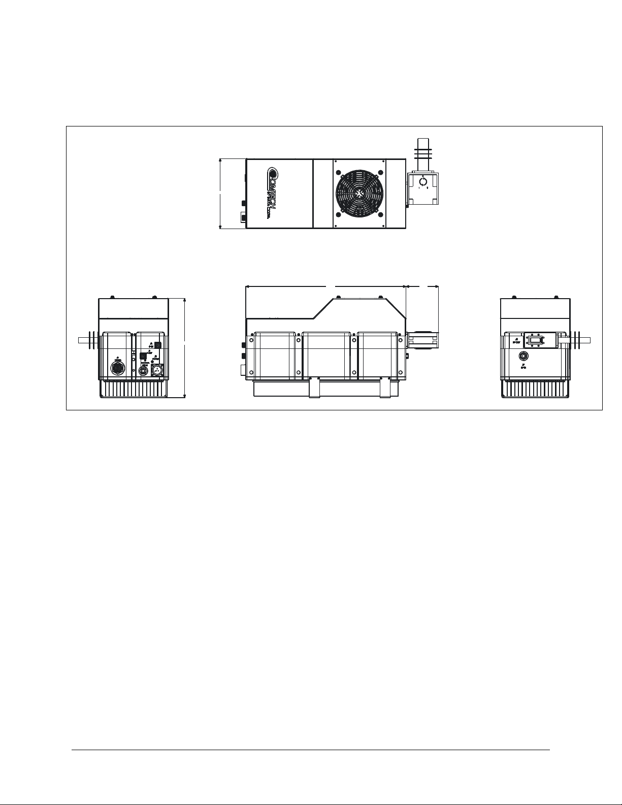
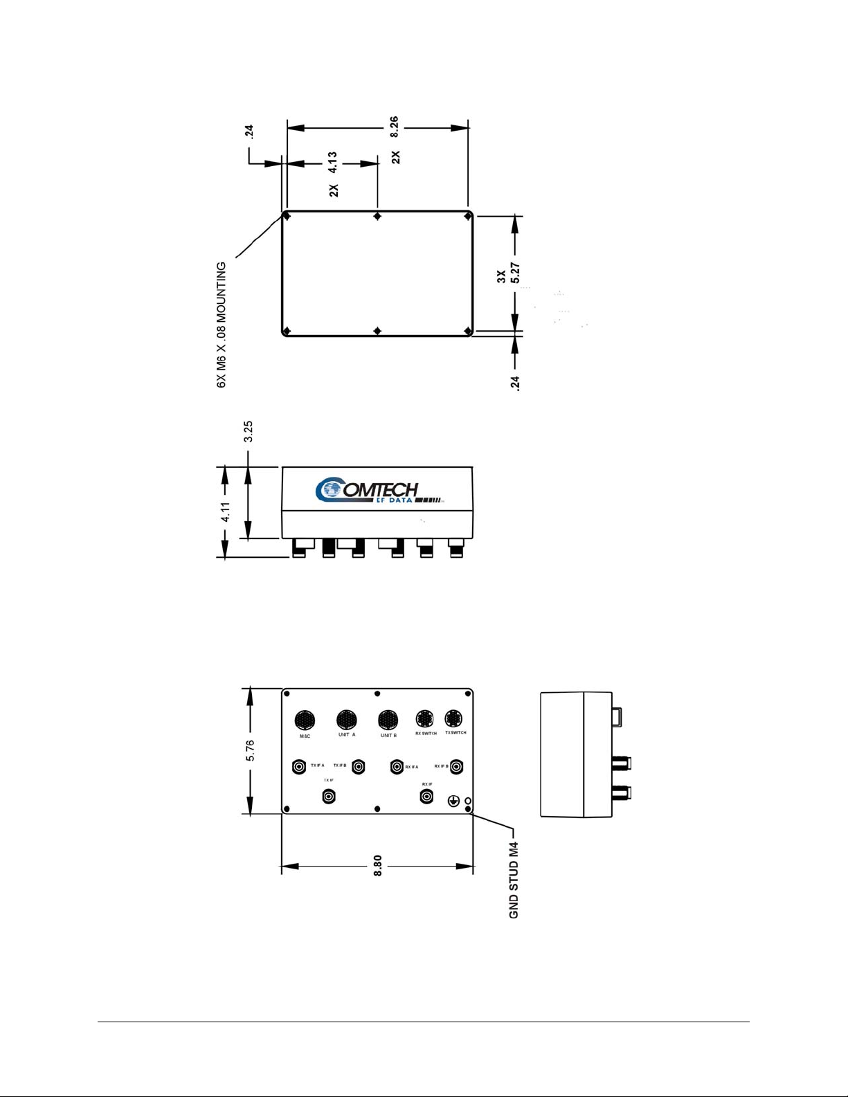
2.2 DIMENSION ENVELOPE
Figure 2-1. 5 to 25-WATT Dimensional Drawing
2-3
Page 24
XSAT7080 X-Band Transciever Revision 0
Specification MN/XSAT7080.IOM
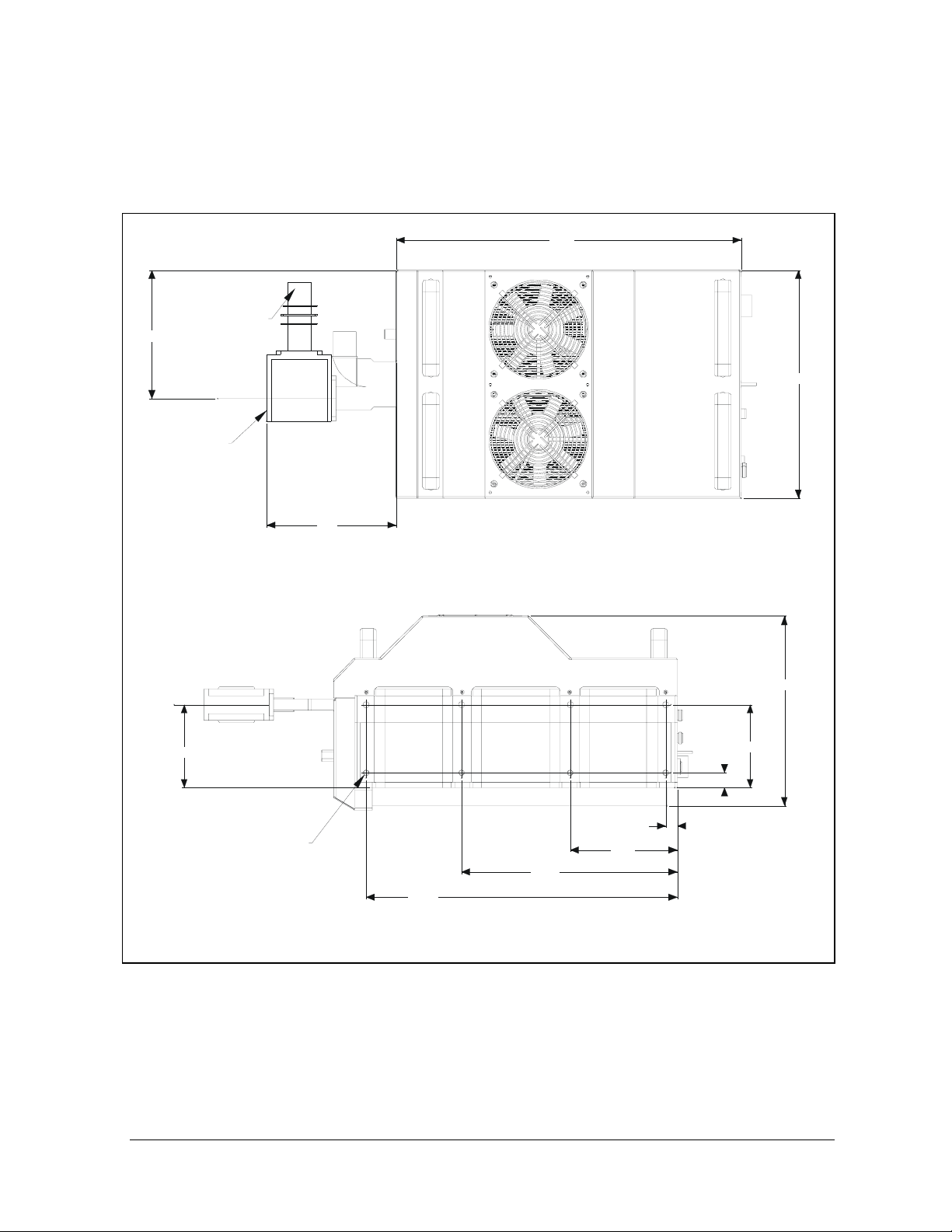
8.14
18.60
11. 52
3.78
Figure 2-2. 50-WATT Dimensional Drawing
2–4
Page 25
XSAT7080 X-Band Transciever Revision 0
Specification MN/XSAT7080.IOM
18.9
5.5
TERMINATION
12.5
OUTPUTPWAVEGUIDE
7.1
CL
10.4
4.6
4.6
.81
8X M8-1.25X8 HELICOILPBOTH SIDES
11.88
17.13
.64
5.89
Figure 2-3. 100-WATT Dimensional Drawing
2-5
Page 26
XSAT7080 X-Band Transciever Revision 0
Specification MN/XSAT7080.IOM
Figure 2-4. Remote Switch Dimensional Drawing
2–6
Page 27
Chapter 3. SYSTEM OPERATION
This section contains instructions for operating the XSAT-7080, X-Band Transceiver.
The Primary customer interface to the XSAT is via the Remote Communications port.
Chapter
on this interface. This chapter will define in detail the controllable parameters provided
via the command/response structure.
3.1 PIN-OUTS
3.1.1 CONNECTOR J3: AC POWER, MAINS, 100 TO 125 VAC, OR
205 TO 240 VAC.
4 provides details regarding the protocol and command/response structure used
To avoid a serious shock hazard, correctly determine the mating
connector type in use and wire it according to the following table:
WARN ING
Early Units Later Units
Pin Mating Connector Type
KPT06J12-3S
MS3116J12-3S
A Line Ground
B Ground Neutral
C Neutral Line
Mating Connector Type
CA3106E18-22SB
3–1
Page 28

XSAT7080 X-Band Transceiver Revision 0
System Operation MN/XSAT7080.IOM
3.1.2 CONNECTOR J5: COMM, REMOTE COMMUNICATIONS PORT.
Mating connector: ITT: KPT06J14-19P or MS3116J14-19P
Connections, see the following table:
Pin Signal I/O Notes
A EIA -485 +RX Input XSAT Receive Line
B EIA -485 –RX Input XSAT Receive Line Compliment
C EIA -485 TX+ Output XSAT Transmit Line
D EIA -485 TX- Output XSAT Transmit Line Compliment
E EIA -232 Rd Input XSAT Receive Line
F REDUNDANT FAULT Input Redundant Controller Status Input
G EIA -232 Td Output XSAT Transmit Line
H AUXCOM Rd Input Auxiliary RS232 Rd used with Redundant Controller
J AUXCOM Td Output Auxiliary RS232 Td used with Redundant Controller
K FAULT COMMON Output
L FAULT NORM OPEN Output Open(OK) / Short(Fault)
M FAULT NORM CLOSED Output Short(OK) / Open(Fault)
N ADDRESS SELECT Input Redundant Addressing
P ONLINE STATUS Input Input from Redundant Controller
R +24V AUX Output 24V output to power Redundant Controller
S REDUNDANCY Input Open (stand-alone) / Gnd (Redundancy)
T GROUND Passive
U GROUND Passive
V NO CONNECT
3–2
Page 29

XSAT7080 X-Band Transceiver Revision 0
System Operation MN/XSAT7080.IOM
3.2 TURNING ON THE XSAT
The XSAT does not contain a ‘Power On/Off’ switch. The XSAT is powered ON by
connecting the J3 “AC Power” connector to the appropriate prime power source. See
Section 1 for detailed requirements for the ‘prime power source’.
Never turn the unit ON without proper termination on the J7 “RF
OUTPUT” port. Individuals can be exposed to dangerously high
WARN ING
In addition, when directly connecting the XSAT to Laboratory Test Equipment, a DC
block should be used between the J2 ‘RF IN’ port and RF test source. The reason for this
is that the XSAT can be configured to supply a 12Vdc, 400 milliamp, LNA Current
Source output on this port. The DC block will protect any test equipment connected
directly to J7.
electromagnetic levels.
3.3 CONFIGURING THE XSAT
The XSAT is a complete RF Down Converter Terminal, RF Up Converter Terminal, and
RF High Power Amplifier (HPA) in a single weather safe package. The following
paragraphs will define the meaning and use of all of the controllable parameter of the
XSAT.
3.3.1 FREQUENCY
Both the Receiver frequency and the Transmitter frequency are user configurable. The
receiver frequency can be selected to any frequency divisible by either 1.0 MHz or 2.5
MHz in the valid Rx frequency range. The transmitter frequency can be selected to any
frequency divisible by either 1.0 MHz or 2.5 MHz in the valid Tx frequency range.
Associated Remote Command(s): DFQ= , UFQ=
3.3.2 ATTENUATION
Both the Receiver attenuation and the Transmitter attenuation are user configurable. The
receiver attenuation can be selected between 00.00 and 20.00 dB in 0.25 dB increments.
The transmitter attenuation can be selected between 00.00 and 25.00 dB in 0.25 dB
increments.
Associated Remote Command(s): DAT= , UAT=
3–3
Page 30

XSAT7080 X-Band Transceiver Revision 0
System Operation MN/XSAT7080.IOM
3.3.3 GAIN OFFSET
Both the Receiver and the Transmitter Gain Offsets are user configurable. The Gain
Offset are only used in redundant configurations. The user can use these parameters to
adjust for gain difference between two XSAT Transceivers used in a 1:1 redundant
configuration. The offset can be selected between 0.00 and –4.00 dB in 0.25 dB
increments.
Associated Remote Command(s): DGO= , UGO=
3.3.4 MUTE MODE
The XSAT offers two operating modes with regards to frequency changes and unit
muting. The two modes are; ‘muted after frequency change’ and ‘unmuted after
frequency change’.
• If the Mute Mode is set to ‘1’, the firmware will leave the IF or RF muted
following a change to either the Down Converter Frequency or Up Converter
Frequency respectively. The operator can then ‘unmute’ the unit using the
commands in the next section.
• If the Mute Mode is set to ‘0’, the firmware will automatically ‘unmute’ the IF or
Associated Remote Command(s): MUT=
3.3.5 MUTE
The output state of both the Receiver and the Transmitter are user controllable. The
receiver output state (the ‘IF IN’ port, J1) will be ON only if the following two
requirements are met:
The transmitter output state (the ‘RF OUT’ port, J7) will be ON only if the following
three requirements are met:
Associated Remote Command(s): DMU= , UMU=
RF following a change to the Down Converter Frequency or Up Converter
Frequency respectively. This assumes that the unit was ‘unmuted’ prior to the
frequency change and that there are no faults following the change. The factory
default for this mode is ‘1’.
(1) The receiver hardware must be fault free
(i.e. No Synthesiser or IFLO faults).
(2) The receiver must be unmuted (i.e. DMU=0 ).
(1) The transmitter hardware must be fault free
(i.e. No Synthesiser or IFLO faults).
(2) The transmitter must be unmuted (i.e. UMU=0).
(3) The transmitter Amplifier must be ON (i.e. AMP=1).
3–4
Page 31

XSAT7080 X-Band Transceiver Revision 0
System Operation MN/XSAT7080.IOM
3.3.6 TX AMPLIFIER
The Tx amplifier ON/OFF state is user controllable. Turning the Tx amplifier OFF
removes the 10Vdc supply to the RF Power FETs. The TX Amplifier must be ON in
order for the XSAT to transmit a RF signal.
Associated Remote Command(s): AMP=
3.3.7 CHANNEL SLOPE ADJUST MODE
Comtech EF Data’s XSAT transcievers provide two operating modes for the Receiver IF
and Transmitter RF output channel slopes; ‘Calibrated’ and ‘Manual’ modes.
• In Calibrated mode, the XSAT firmware uses a calibration ‘lookup’ table based
on the selected frequency to determine the optimum channel slope setting.
• In Manual mode, the customer adjusts the channel slope using the DSA and USA
commands defined in the next section.
Associated Remote Command(s): DSM=, USM=
3.3.8 CHANNEL SLOPE ADJUST
Both the Rx IF output and the Tx RF output channel slopes are user controllable.
• The receiver channel slope can be varied for approximately 2dB of positive slope.
The parameter for controlling this is the ‘Down Slope Adjust’ which can be
varied from 0.0 to 1.0 in 0.1 steps. 0.0 is the default setting and also is the value
used when the channel flatness is tuned and tested in the factory. 1.0 corresponds
to approximately 2dB of positive slope.
• The transmit channel slope can be varied for approximately 2dB of positive slope.
The parameter for controlling this is the ‘Up Slope Adjust’ which can be varied
from 0.0 to 1.0 in 0.1 steps. 0.0 is the default setting and also is the value used
when the channel flatness is tuned and tested in the factory. 1.0 corresponds to
approximately 2dB of positive slope.
Associated Remote Command(s): DSA= , USA=
3–5
Page 32

XSAT7080 X-Band Transceiver Revision 0
System Operation MN/XSAT7080.IOM
3.3.9 REFERENCE FREQUENCY ADJUST
A manual, fine adjustment of the internal 10MHz reference frequency is provided as a
user controllable parameter. This parameter can be varied within the range 000 to 255,
with the factory default setting at 087. Varying this parameter from 000 to 255 will result
in a change of approximately 6.5 kHz and 4.0 kHz at the RF and IF output ports
respectively.
Associated Remote Command(s): REF=
3.3.10 EXTERNAL REFERENCE FAULT LOGIC
The XSAT allows the user to select whether or not the summary fault relay is activated if
the internal 10MHz reference loses lock with the external reference attached to
‘EXTERNAL REF IN port’ J4.
(The factory default is 0)
Associated Remote Command(s): LFL=
3.3.11 COLD START FUNCTION
The XSAT provides an optional ‘Cold Start’ feature that will ensure that the internal
10MHz reference signal is at a stable temperature prior to allowing the RF and IF outputs
to be turned ON. A fixed cold start interval of 15 minutes is used.
• If ‘Cold Start’ is ON when the XSAT is powered ON, the IF and RF outputs will
remain muted for 15 minutes even if all the conditions defined in 3.2.5 are
satisfied. At the end of the 15 minute interval, the RF and IF output will
automatically be turned ON if the conditions of 3.2.5 are met.
• If a XSAT was powered ON with ‘Cold Start ON’, the operator can override this
function by setting ‘Cold Start OFF’.
Associated Remote Command(s): CLD=
3.3.12 AUTO FAULT RECOVERY
This parameter defines how the XSAT responds to momentary fault conditions.
• If ‘Auto Fault Recovery ’ is OFF and a fault condition occurs that causes either
the RF or IF output to be muted, then that fault condition clears, the XSAT will
remain muted. In this mode, operator intervention is necessary to return the XSAT
to normal operating mode.
3–6
Page 33

XSAT7080 X-Band Transceiver Revision 0
System Operation MN/XSAT7080.IOM
• If ‘Auto Fault Recovery’ is ON and the same situation occurs, the XSAT will
automatically be unmuted and return to normal operating mode. To protect
against repetitive, momentary faults, if the XSAT experiences five occurrences of
the same fault, the ‘Auto Fault Recovery’ parameter will automatically be set to
OFF.
Example: If the Up Converter IFLO synthesizer goes unlocked and starts
sweeping while Auto Fault Recovery is ON, the XSAT would see a unlocked /
locked condition at the sweep rate of the IFLO synthesizer. After the 5th
occurrence the firmware will set Auto Fault Recovery to OFF and keep the
XSAT RF output muted.
Associated Remote Command(s): AFR=
3.3.13 LNA CURRENT SOURCE
The XSAT has the circuitry necessary to source current, at 12 Vdc, up the “RF IN” port
J2, to power a LNA. This current source can be turned ON/OFF via the user. This source
is capable of providing up to 400 mA.
Never turn the unit ON without proper termination on the J7 “RF
OUTPUT” port. Individuals can be exposed to dangerously high
WARN ING
electromagnetic levels.
Exercise care when directly connecting the XSAT to Laboratory Test
Equipment. A DC block should be used between the J2 “RF IN”’ port
IMPORTAN T
and RF test source to protect the test equipment in case the source is
accidentally turned ON. (The factory default is OFF).
Associated Remote Command(s): LCS=
3.3.14 LNA CURRENT CALIBRATION AND CURRENT WINDOW
The XSAT provides the capability to monitor the LNA current when configured to
supply current to a LNA. In addition, an adjustable window detect for the LNA current is
provided. After attaching the LNA and turning on the current source, the user can
‘Calibrate’ the current and set a window from ±20% to ±50% to trigger an alarm. The
user can disable the ‘window detect’ feature by setting the window value to ±99%. (The
factory default is 99)
Associated Remote Command(s): CAL= , LCW=
3–7
Page 34

XSAT7080 X-Band Transceiver Revision 0
System Operation MN/XSAT7080.IOM
3.3.15 LNA FAULT LOGIC
The XSAT allows the user to select whether or not the summary fault relay is activated if
the LNA current moves out the prescribed window. This allows the user to control
whether or not the redundancy controller will switch on a LNA current alarm in the
redundant configuration. (The factory default is 0)
Associated Remote Command(s): LFL=
3.3.16 REDUNDANCY CONTROLLER AUTO/MANUAL
The Operating mode of the Comtech EF Data Redundant Switch Unit (RSU-5060) can be
set via a command to the ONLINE XSAT. The RSU-5060 initializes to the AUTO mode
when power is first applied.
• In AUTO mode the RSU-5060 monitors the state of the two XSATs and will
automatically switch the OFFLINE unit online if the ONLINE unit faults.
• In MANUAL mode, the RSU-5060 will only switch the position of the Tx and Rx
transfer switches when commanded to do so via either the RTG= command or via
Pin V on the ‘M&C Control’ connector (J5) on the RSU-5060. The user sets
AUTO mode by sending a ‘1’ in the data field and MANUAL mode with a ‘0’ in
the data field.
Associated Remote Command(s): RAM=
3.3.17 REDUNDANCY CONTROLLER TOGGLE
The User can cause the RSU-5060 Redundant Switch Unit to switch the position of both
the Tx and Rx transfer switches using this command.
• If the RSU-5060 is in AUTO mode, the command will only cause a switchover if
the OFFLINE unit is currently UNFAULTED.
• If the RSU-5060 is in MANUAL mode, the command will cause a switchover
independent of the state of the OFFLINE unit.
Associated Remote Command(s): RTG=
3–8
Page 35

XSAT7080 X-Band Transceiver Revision 0
System Operation MN/XSAT7080.IOM
3.3.18 SET PHYSICAL ADDRESS
The Remote (Physical) address to which the XSAT will respond can be set to any value
between 0001 and 9999. (The factory default is 0001)
Associated Remote Command(s): SPA=
3.3.19 SET BAUD RATE
The Baud Rate of the communication port, J5, can be set to any values shown below:
1200, 2400, 4800, 9600, 19200, 38400 (The factory default is 9600)
Associated Remote Command(s): SBR=
3.3.20 SET DATE
The XSAT contains a battery powered Real Time Clock (RTC) used to provide
Date/Time stamping of events, alarms and faults. The date can be changed by the user.
Associated Remote Command(s): DAY=
3.3.21 SET TIME
The XSAT contains a battery powered Real Time Clock (RTC) used to provide
Date/Time stamping of events, alarms and faults. The time can be changed by the user.
Associated Remote Command(s): TIM=
3–9
Page 36

XSAT7080 X-Band Transceiver Revision 0
System Operation MN/XSAT7080.IOM
Notes:
______________________________________________________________________________
______________________________________________________________________________
______________________________________________________________________________
______________________________________________________________________________
______________________________________________________________________________
______________________________________________________________________________
______________________________________________________________________________
______________________________________________________________________________
______________________________________________________________________________
______________________________________________________________________________
______________________________________________________________________________
______________________________________________________________________________
______________________________________________________________________________
______________________________________________________________________________
______________________________________________________________________________
______________________________________________________________________________
______________________________________________________________________________
______________________________________________________________________________
______________________________________________________________________________
______________________________________________________________________________
______________________________________________________________________________
______________________________________________________________________________
______________________________________________________________________________
______________________________________________________________________________
______________________________________________________________________________
______________________________________________________________________________
______________________________________________________________________________
______________________________________________________________________________
______________________________________________________________________________
______________________________________________________________________________
______________________________________________________________________________
______________________________________________________________________________
______________________________________________________________________________
______________________________________________________________________________
______________________________________________________________________________
______________________________________________________________________________
______________________________________________________________________________
______________________________________________________________________________
______________________________________________________________________________
______________________________________________________________________________
______________________________________________________________________________
______________________________________________________________________________
3–10
Page 37

Chapter 4. REMOTE CONTROL
4.1 INTRODUCTION
This document describes the protocol and message repertoire for remote monitor and control of
the XSAT Outdoor terminal.
The electrical interface is either an RS-485 multi-drop bus (for the control of many devices) or an
RS-232 connection (for the control of a single device), and data is transmitted in asynchronous
serial form, using ASCII characters. Control and status information is transmitted in packets, of
variable length, in accordance with the structure and protocol defined in later sections.
4.1.1 RS-485
The RS-485 interface is provided at the 19-pin circular J5 connector. The interface is a 4-wire
RS-485 interface using the pin out shown in Table 4-1. Since a half-duplex communication
protocol is used, the +Tx and +Rx as well as the –Tx and –Rx signals can be tied together at the
user end to support a 2-wire interface. The RS-485 driver is only active during transmission and
is tri-stated when not is use.
Table 4-1. RS-485 Interface
Pin Signal Name I/O Notes
A RS--485 +Rx Input XSAT Receive line
B RS--485 –Rx Input XSAT Receive line complement
C RS--485 +Tx Output XSAT Transmit line
D RS--485 –Tx Output XSAT Transmit line complement
T Ground Passive
4-1
Page 38

XSAT7080 X-Band Transceiver Revision 0
Remote Control MN/XSAT7080.IOM
4.1.2 RS-232
The RS-232 interface is provided at the 19-pin circular J5 connector. The interface provides the
five signals shown in Table 4-2. The XSAT only requires three wires (TD, RD, and Ground), the
other two signal are provided for terminal equipment that requires RTS/CTS handshaking. The
XSAT simply ties these two signals together.
Table 4-2. RS-232 interface
Pin Signal Name I/O Notes
E RS-232 RD Input XSAT Rx line
G RS-232 TD Output XSAT Tx line
T Ground Passive
4.2 BASIC PROTOCOL
Whether in RS-232 or RS-485 mode, all data is transmitted half-duplex as asynchronous serial
characters suitable for transmission and reception by a UART. In this case, the asynchronous
character format is fixed at; 8 data bits, 1 stop bit, no parity. The baud rate may vary between
1200 baud and 19,200 baud.
All data is transmitted in framed packets. The master is assumed to be a PC or ASCII dumb
terminal, which is controlling the process of monitor and control. The master is the only device
that is permitted to initiate the transmission of data. Slaves are only permitted to transmit when
they have been specifically instructed to do so by the master.
All bytes within a packet are printable ASCII characters. In this context, the Carriage Return and
Line Feed characters are considered printable.
All messages from master to slave require a response (with one exception). This will either be to
return data that has been requested by the master, or to acknowledge reception of an instruction to
change the configuration of the slave. The exception to this is when the master broadcasts a
message (such as Set time/date) using Address 0.
4-2
Page 39

XSAT7080 X-Band Transceiver Revision 0
Remote Control MN/XSAT7080.IOM
4.2.1 PACKET STRUCTURE
Table 4-3. Master-to-Slave:
Start of
Packet
Character
< / = or ?
ASCII
Code
#
Characters
60
1 4 1 3 1 n 1
Device
Address
Address
Delimiter
47
Example: <0135/UAT=12.25{CR}
Table 4-4. Slave-to-Master:
Character
ASCII
Code
#
Characters
Start of Packet
> / =, ?, !, or *
62 47 61, 63, 33
1 4 1 3 1 From 0 to n 2
Device
Address
Address
Delimiter
Example: >0135/UAT=07.75{CR}{LF}
Instruction
Code
Instruction
Code
Code
Qualifier
61 or 63
Code
Qualifier
or 42
Optional
Arguments
13
Optional
Arguments
End of
Packet
Carriage
Return
End of Packet
Carriage
Return, Line
Feed
13, 10
4.2.1.1 START OF PACKET
Master to Slave: This is the character: < = (ASCII code 61)
Master to Slave: This is the character: > = (ASCII code 62)
Because this is used to provide a reliable indication of the start of packet, these two characters
may not appear anywhere else within the body of the message.
4-3
Page 40

XSAT7080 X-Band Transceiver Revision 0
Remote Control MN/XSAT7080.IOM
4.2.1.2 ADDRESS
Up to 9999 devices can be uniquely addressed. In RS-232 and RS-485 applications, the
permissible range of values is 1 to 9999. It is programmed into a slave unit using the Set Physical
Address (SPA) command.
The master sends a packet with the address of a slave - the destination of the packet.
When the slave responds, the address used is the same address, to indicate to the
IMPORTAN T
master the source of the packet. The master does not have its own address.
4.2.1.3 INSTRUCTION CODE
This is a three-character alphabetic sequence that identifies the subject of the message. Wherever
possible, the instruction codes have been chosen to have some significance.
For example UAT for Up Converter attenuation, UFQ for Up Converter Frequency, etc. This aids in
the readability of the message, should it be displayed in its raw ASCII form. All command are case
sensitive, only upper case alphabetic characters may be used (A-Z, ASCII codes 65 - 90).
4.2.1.4 INSTRUCTION CODE QUALIFIER
This is a single character that further qualifies the preceding instruction code.
Code Qualifiers obey the following rules:
1) From Master to Slave, the only permitted values are:
= (ASCII code 61)
? (ASCII code 63)
They have these meanings:
The = code (master to slave) is used as the assignment operator, and is used to indicate
that the parameter defined by the preceding byte should be set to the value of the
argument(s) which follow it.
For example, in a message from master to slave, UAT=12.50 would mean set the transmit
attenuation to 12.50 dB.
The ? code (master to slave) is used as the query operator, and is used to indicate that the
slave should return the current value of the parameter defined by the preceding byte.
4-4
Page 41

XSAT7080 X-Band Transceiver Revision 0
Remote Control MN/XSAT7080.IOM
For example, in a message from master to slave, ‘UAT?’ would mean return the current
value of the transmit attenuation.
2) From Slave to Master, the only permitted values are:
= (ASCII code 61)
? (ASCII code 63)
! (ASCII code 33)
* (ASCII code 42)
# (ASCII code 35)
They have these meanings:
The = code (slave to master) is used in two ways:
• First, if the master has sent a query code to a slave (for example UAT?, meaning
what’s the Transmit Attenuation?), the slave would respond with UAT=xx.xx,
where xx.xx represents the attenuation in question.
• Second, if the master sends an instruction to set a parameter to a particular value,
then, providing the value sent in the argument is valid, the slave will
acknowledge the message by replying with UAT= (with no message arguments).
The ? code (slave to master) is only used as follows:
• If the master sends an instruction to set a parameter to a particular value, then, if
the value sent in the argument is not valid, the slave will acknowledge the
message by replying with (for example) with UAT? (with no message
arguments).
• This indicates that there was an error in the message sent by the master.
The * code (slave to master) is only used as follows:
• If the master sends an instruction to set a parameter to a particular value, then, if
the value sent in the argument is valid, but the XSAT will not permit that
particular parameter to be changed at that time, the slave will acknowledge the
message by replying with (for example) with UAT* (with no message
arguments).
The ! code (slave to master) is only used as follows:
• If the master sends an instruction code which the slave does not recognise, the
slave will acknowledge the message by echoing the invalid instruction, followed
by the ! character. Example: XYZ!
4-5
Page 42

XSAT7080 X-Band Transceiver Revision 0
Remote Control MN/XSAT7080.IOM
The # code (slave to master) is only used as follows:
• If the master sends an instruction code which the slave cannot currently perform
because of hardware resource issues, the slave will acknowledge the message by
echoing the invalid instruction, followed by the # character.
• This response can only occur if the operator sends two or more ‘hardware
configuration’ type commands without allowing adequate time between
commands for the hardware to be configured.
Example; the operator issued commands to change both the Up Converter
frequency and the down converter frequency with less than 100 milliseconds
between commands
• If this response is returned the command has not been excepted an the operator
must resend the command.
4.2.1.5 MESSAGE ARGUMENTS
Arguments are not required for all messages. All arguments are ASCII codes for the characters 0
to 9 (ASCII 48 to ASCII 57), period (ASCII 46) and comma (ASCII 44).
4.2.1.6 END OF PACKET
Master to Slave: This is the Carriage Return character (ASCII code 13)
Slave to Master: This is the two-character sequence Carriage Return, Line Feed. (ASCII code 13,
and code 10.)
Both indicate the valid termination of a packet.
4.3 COMMANDS OR RESPONSES
The commands and responses a reprovided to assist the technican in monitoring and controlling
the unit
.
4-6
Page 43

XSAT7080 X-Band Transceiver Revision 0
Remote Control MN/XSAT7080.IOM
Parameter
Type
Tx
Frequency
Rx
Frequency
Tx
Attenuation
Rx
Attenuation
Tx Gain
Offset
Rx Gain
Offset
Tx Amplifier AMP= 1 byte,
Command
(Instruction
Code and
qualifier)
UFQ= 6 bytes
DFQ= 6 bytes
UAT= 5 bytes
DAT= 5 bytes
UGO= 5 bytes
DGO= 5 bytes
Arguments
for
Command
or
Response
to Query
numerical
numerical
numerical
numerical
numerical
numerical
value of
0,1
Description of Arguments
Note that all arguments are ASCII
numeric codes between 48 and 57.
Command or Query.
Tx Frequency in valid range.
Frequency divisible by 1Mhz and 2.5 MHz are allowed.
Example: UFQ= 7951.0
Command or Query.
Rx Frequencyin valid range.
Frequency divisible by 1Mhz and 2.5 MHz are allowed.
Example: DFQ=7251.0
Command or Query.
Tx Attenuation, in dB, between 00.00 and 25.00.
Resolution = 00.25 dB.
Example: UAT=12.75
Command or Query.
Rx Attenuation, in dB, between 00.00 and 20.00.
Resolution = 00.25 dB.
Example: DAT=12.75
Command or Query.
Tx Gain Offset for 1:1 redundancy configurations.
In dB, between -0.00 and -4.00. Resolution = 00.25 dB.
Example: UGO=-1.25
Command or Query.
Rx Gain Offset for 1:1 redundancy configurations.
In dB, between -0.00 and -4.00. Resolution = 00.25 dB.
Example: DGO=-1.25
Command or Query.
Tx Amplifier, where:
0 = Amplifier OFF
1 = Amplifier ON
Example: AMP=1
Response to
Command
(Slave to Master)
UFQ= (message ok)
UFQ? (received ok,
but invalid
arguments found)
DFQ= (message ok)
DFQ? (received ok,
but invalid
arguments found)
UAT= (message ok)
UAT? (received ok,
but invalid
arguments found)
DAT= (message ok)
DAT? (received ok,
but invalid
arguments found)
UGO= (message ok)
UGO? (received ok,
but invalid
arguments found)
DGO= (message ok)
DGO? (received ok,
but invalid
arguments found)
AMP= (message ok)
AMP? (received ok,
but invalid argument
found)
Query
(Instruction
code and
qualifier)
UFQ? UFQ=xxxx.x (same format as
DFQ? DFQ=xxxx.x (same format as
UAT?
DAT? DAT=xx.xx
UGO? UGO=xx.xx
DGO? DGO=xx.xx
AMP? AMP=x
Response to Query
(Slave to Master)
command arguments)
command arguments)
UAT=xx.xx
(same format as command
arguments)
(same format as command
arguments)
(same format as command
arguments)
(same format as command
arguments)
(same format as command
argument)
4-7
Page 44

XSAT7080 X-Band Transceiver Revision 0
Remote Control MN/XSAT7080.IOM
Parameter
Type
Mute Mode MUT= 1 byte,
Tx Mute UMU= 1 byte,
Rx Mute DMU= 1 byte,
Tx Slope
Mode
Tx Slope
Adjust
Rx Slope
Mode
Command
(Instruction
Code and
qualifier)
USM= 1 byte,
USA= 3 bytes Command or Query.
DSM= 1 byte,
Arguments
for
Command
or
Response
to Query
value of 0,1
value of 0,1
value of 0,1
value of 0,1
value of 0,1
Description of Arguments
Note that all arguments are ASCII
numeric codes between 48 and 57.
Command or Query.
Mute Mode, where:
0 = Unmuted after Frequency change,
1 = Muted after Frequency change.
Example: MUT=1
Command or Query.
Tx Mute, where:
0 = Transmitter Unmuted,
1 = Transmitter Muted
Example: UMU=1
Command or Query.
Rx Mute, where:
0 = Receiver Unmuted,
1 = Receiver Muted
Example: DMU=1
Command or Query.
Tx Slope Mode, where:
0 =Manual Mode,
1 = Calibrated Mode.
Example: USM=1
Tx Slope Adjust, between 0.0 and 1.0.
Resolution = 0.1.
Example: USA=0.3
Command or Query.
Rx Slope Mode, where:
0 =Manual Mode,
1 = Calibrated Mode.
Example: DSM=1
Response to
Command
(Slave to Master)
MUT=(message ok)
MUT?(received ok,
but invalid argument
found)
UMU=(message ok)
UMU?(received ok,
but invalid argument
found)
DMU=(message ok)
DMU?(received ok,
but invalid argument
found)
USM=(message ok)
USM?(received ok,
But invalid argument
found)
USA= (message ok)
USA? (received ok,
but invalid arg.
found)
DSM=(message ok)
DSM?(received ok,
But invalid argument
found)
Query
(Instruction
code and
qualifier)
MUT? MUT=x
UMU? UMU=x
DMU? DMU=x
USM? USM=x
USA? USA=x.x
DSM? DSM=x
Response to Query
(Slave to Master)
(same format as command
argument)
(same format as command
argument)
(same format as command
argument)
(same format as command
argument)
(same format as command
argument)
(same format as command
argument)
4-8
Page 45

XSAT7080 X-Band Transceiver Revision 0
Remote Control MN/XSAT7080.IOM
Parameter
Type
Rx Slope
Adjust
Reference
Oscillator
Adjust
Cold Start CLD= 1 byte,
Auto Fault
Recovery
Online
Status
LNA Current
Source
Command
(Instruction
Code and
qualifier)
DSA= 3 bytes Command or Query.
REF= 3 bytes Command or Query.
AFR= 1 byte,
N/A 1 byte,
LCS= 1 byte,
Arguments
for
Command
or
Response
to Query
value of 0,1
value of 0,1
value of 0,1
value of 0,1
Description of Arguments
Note that all arguments are ASCII
numeric codes between 48 and 57.
Rx Slope Adjust, between 0.0 and 1.0.
Resolution = 0.1.
Example: DSA=0.3
Ref Osc Adjust, between 000 and 255.
Resolution 001.
Example: REF=087
Note: REF cannot be adjusted when the XSAT
is locked to an external reference source.
Command or Query.
Cold Start, where:
0 = Disabled,
1 = Enabled
Example: CLD=1
Command or Query.
Auto Fault Recovery, where:
0 = Disabled,
1 = Enabled
Example: AFR=1
Query Only.
Online status, where:
0 = OFFLINE,
1 = ONLINE
Example: ONL=1
Command or Query.
LNA Current Source, where:
0 = Disabled,
1 = Enabled
Example: LCS=1
Response to
Command
(Slave to Master)
DSA= (message ok)
DSA? (received ok,
but invalid arg.
found)
REF= (message ok)
REF? (received ok,
but invalid argument
found)
REF* (message ok,
but not permitted in
current mode)
CLD= (message ok)
CLD? (received ok,
but invalid
arguments found)
AFR= (message ok)
AFR? (received ok,
but invalid
arguments found)
ONL= (message ok)
ONL? (received ok,
but invalid
arguments found)
LCS= (message ok)
LCS? (received ok,
but invalid
arguments found)
Query
(Instruction
code and
qualifier)
DSA? DSA=x.x
REF? REF=xxx
CLD?
AFR?
ONL?
LCS?
Response to Query
(Slave to Master)
(same format as command
argument)
(same format as command
argument)
CLD=x
(same format as command
arguments)
AFR=x
(same format as command
arguments)
ONL=x
(same format as command
arguments)
LCS=x
(same format as command
arguments)
4-9
Page 46

XSAT7080 X-Band Transceiver Revision 0
Remote Control MN/XSAT7080.IOM
Parameter
Type
LNA Fault
Logic
Calibrate
LNA Current
LNA Current
Window
External
Reference
Fault Logic
Command
(Instruction
Code and
qualifier)
LFL= 1 byte,
CAL= None Command only.
LCW= 2 bytes,
XRF= 1 byte,
Arguments
for
Command
or
Response
to Query
value of 0,1
numerical
value of 0,1
Description of Arguments
Note that all arguments are ASCII
numeric codes between 48 and 57.
Command or Query.
LFL controls whether or not the Summary Fault Relay
(SFR)
is affected by the LNA Current window monitor, where:
0 = A LNA Current fault does not effect the SFR,
1 = A LNA Current fault will effect the SFR.
Example: LFL=1
This command is used to set the calibration point for
the LNA current alarm feature.
Example: CAL=
Command or Query.
LNA Current Monitor Window, this command allows the
user to set the alarm window in ± % of the calibrated
LNA current. Valid inputs are 20 to 50 in increments of
5. In addition, setting the value to 99 disables the alarm
function.
Example: LCW=30, set the alarm window at ± 30%.
Command or Query.
XRF controls whether or not the Software monitors the
external refernece source. If enabled and no source is
present a fault will be reported.
0 = A Ext Reference not monitored
1 = A Ext Reference is monitored and the lock state
reported.
Example: XRF=1
Response to
Command
(Slave to Master)
LFL= (message ok)
LFL? (received ok,
But invalid
arguments found)
CAL= (message ok) N/A
LCW= (message ok)
LCW? (received ok,
but invalid
arguments found)
XRF= (message ok)
XRF? (received ok,
But invalid
arguments found)
Query
(Instruction
code and
qualifier)
LFL?
LCW?
XRF?
Response to Query
(Slave to Master)
LFL=x
(same format as command
arguments)
N/A
LCW=xx
(same format as command
arguments)
XRF=x
(same format as command
arguments)
4-10
Page 47

XSAT7080 X-Band Transceiver Revision 0
Remote Control MN/XSAT7080.IOM
Parameter
Type
XSAT Global
Configuration
Command
(Instruction
Code and
qualifier)
CGC= 60 bytes,
Arguments
for
Command
or
Response
to Query
with
numerical
entries
fixed value
entries, and
delimiters
Description of Arguments
Note that all arguments are ASCII
numeric codes between 48 and 57.
Command or Query. Global configuration of Unit, in the
form: FFFF.FAA.AAMSB.BGG.GGZffff.faa.aamsb.b
gg.ggNRCXOOOLWWDeeeeeee, where:
F = Tx Frequency – same as UFQ= (6 bytes)
A = Tx Attenuation – same as UAT= (5 bytes)
M = Tx Mute – same ad UMU= (1byte)
S = Tx Slope Mode – same as USM= (1 byte)
B = Tx Slope Value – same as USA= (3 bytes)
G = Tx Gain Offset – same as UGO= (5 bytes)
Z = Tx Amplifier State – same as AMP= (1 byte)
f = Rx Frequency – same as UFQ= (6 bytes)
a = Rx Attenuation – same as UAT= (5 bytes)
m = Rx Mute – same ad UMU= (1byte)
s = Rx Slope Mode – same as USM= (1 byte)
b = Rx Slope Value – same as USA= (3 bytes)
g = Rx Gain Offset – same as UGO= (5 bytes)
N = Mute Mode – same as MUT= (1 byte)
R = Auto Fault Recovery – same as AFR= (1 byte)
C = Cold Start Mode – same as CLD= (1 byte)
X = Ext Ref Fault Logic – same as XRF= (1 byte)
O = Ref Oscillator Adjust – same as REF= (3 bytes)
L = LNA Current Source – same as LCS= (1 byte)
W = LNA Current Window – same as LCW= (3 bytes)
D = LNA Fualt Logic – same as LFL= (1 byte)
e = expansion (7 bytes), set to ‘0’
Example: CGC=7951.012.75000.3-0.0017251.0
12.75000.3-0.00110108719900000000
Response to
Command
(Slave to Master)
CGC= (message ok)
CGC? (received ok,
But invalid
arguments found)
Query
(Instruction
code and
qualifier)
CGC?
Response to Query
(Slave to Master)
CGC= FFFF.FAA.AAMS
B.BGG.GGZffff.faa.aams
b.bgg.ggNRCXOOOLWWDeeeeee
e
(same format as command
arguments)
4-11
Page 48

XSAT7080 X-Band Transceiver Revision 0
Remote Control MN/XSAT7080.IOM
Parameter
Type
Redundancy
Controller
Box
Auto/Manual
Mode
Redundancy
Controller
Box Toggle
Remote
Address
(Physical
Address)
Remote
Baud rate
Set RTC
Date
Command
(Instruction
Code and
qualifier)
RAM= 1 byte,
RTG= None Command only.
SPA= 4 bytes,
SBR= 4 bytes Command or Query.
DAY= 6 bytes,
Arguments
for
Command
or
Response
to Query
value of 0,1
numerical
numerical
Description of Arguments
Note that all arguments are ASCII
numeric codes between 48 and 57.
Command or Query.
RAM controls whether or not the Redundancy Controller
is in automatic or manual mode, where:
0 = Manual Mode,
1 = Auto Mode.
Example: RAM=1
RTG= sent to the online XSAT will cause the
Redundancy Box to toggle the Tx and Rx switches.
Example: RTG=
Command or Query.
Physical Address - between 0001 and 9999.
Resolution 0001.
Example: SPA=0890
Baud Rate, as follows:
1200 = 1200 baud,
2400 = 2400 baud,
4800 = 4800 baud,
9600 = 9600 baud,
19K2 = 19200 baud.
38K4 = 38400 baud.
A command in the form mmddyy, where; dd = day of the
month, between 01 and 31, mm = month of the year,
between 01 and 12 and yy = year, between 97 and 96
(1997 to 2000, then 2000 to 2096)
Example: DAY=042457 would be April 24, 2057
Response to
Command
(Slave to Master)
RAM= (message ok)
RAM? (received ok,
But invalid
arguments found)
RTG= (message ok)
RTG? (received ok,
But invalid
arguments found)
SPA= (message ok)
SPA? (received ok,
but invalid
arguments found)
SBR= (message ok)
SBR? (received ok,
but invalid
arguments found)
DAY= (message ok)
DAY? (received ok,
but invalid
arguments found)
DAY* (message ok,
but not permitted in
current mode
Query
(Instruction
code and
qualifier)
RAM?
N/A
SPA? SPA=xxxx
SBR? SBR=xxxx
DAY? DAY=xxxxxx
Response to Query
(Slave to Master)
RAM=x
(same format as command
arguments)
N/A
(same format as command
arguments)
(same format as command
arguments)
(same format as command
arguments
4-12
Page 49

XSAT7080 X-Band Transceiver Revision 0
Remote Control MN/XSAT7080.IOM
Parameter
Type
Set RTC
Time
Clear All
Stored
Alarms
Re-Initialize
Retrieved
Alarms Point
List New
Alarms
(Retrieve
next 5
unread
Stored
Alarms)
Command
(Instruction
Code and
qualifier)
TIM= 6 bytes,
CAA= None Command only
IAP= None Command only
N/A 145 bytes Query only
Arguments
for
Command
or
Response
to Query
numerical
Description of Arguments
Note that all arguments are ASCII
numeric codes between 48 and 57.
A command in the form hhmmss, indicating the time
from midnight, where hh = hours, between 00 and 23;
mm = minutes, between 00 and 59, and ss = seconds,
between 00 and 59
Example: TIM=231259 would be 23 hours, 12 minutes
and 59 seconds from midnight.
Instructs the slave to clear all Stored Events
This command takes no arguments.
Instructs the unit to zero the retrieved alarms pointer to
allow the user to retrieve the complete stored alarms
log.
XSAT returns the oldest 5 Stored Events that have not
yet been read over the remote control. Reply format:
Sub-body{CR}Sub-body{CR}Sub-body{CR}Subbody{CR}Sub-body, where Sub-body=
YYYYYYYYYY ZZ mmddyy hhmmss,
YYYYYYYYYY being the fault description.
ZZ being the alarm typr.
FT = Fault
OK = Clear
IF = Information
If there are no new events, the XSAT will reply with
LNA*. Note: the XSAT incorporates a circular buffer
capable of holding 100 events/alarms.
Response to
Command
(Slave to Master)
TIM= (message ok)
TIM? (received ok,
but invalid
arguments found)
TIM* (message ok,
but not permitted in
current mode
CAA= (message ok) N/A N/A
IAP=(message ok) N/A N/A
N/A LNA? LNA=YY..ss
Query
(Instruction
code and
qualifier)
TIM? TIM=xxxxxx
Response to Query
(Slave to Master)
(same format as command
arguments
(see description for details of
arguments)
4-13
Page 50

XSAT7080 X-Band Transceiver Revision 0
Remote Control MN/XSAT7080.IOM
Parameter
Type
Total New
Alarms
(Retrieve
Number of
unread
Stored
Alarms)
Retrieve
Serial
Number
Retrieve
Equipment
Type
Circuit
Identification
Message
Command
(Instruction
Code and
qualifier)
N/A 2 bytes,
N/A 6 bytes,
N/A 20 bytes,
CID= 24 bytes,
Arguments
for
Command
or
Response
to Query
numerical
alpha
numerical
C00000 to
C99999
alpha
numerical
alpha
numerical
Description of Arguments
Note that all arguments are ASCII
numeric codes between 48 and 57.
Query only.
XSAT returns the number of Stored Events which
remain unread, in the form xx. Note: This means unread
over the remote control – viewing the stored events
from the front panel of the modem does not affect this
value.
Example reply: TNA=18’cr’’lf’
Query only.
Used to Query the units 6 digit serial number.
Slave returns its S/N, in the form xxxxxx.
Example: RSN=C00165’cr’’lf’
Query only.
XSAT returns a string indicated the Model Number and
the value of internal software revision installed
Example: RET=XSAT-7080/025 V1.02’cr’’lf’
Command or Query.
Sets or queries the user-defined Circuit ID string, which
is a fixed length of 24 characters.
Valid characters include:
Space ( ) * + _ , . / 0-9 A-Z
Response to
Command
(Slave to Master)
N/A TNA? TNA=xx (see description for details
N/A RSN? RSN=xxxxxx (see description for
N/A RET? RET=x….x (see description for
CID= (message ok)
CID? (received ok,
but invalid
arguments found)
Query
(Instruction
code and
qualifier)
CID? CID=x….x (see description for
Response to Query
(Slave to Master)
of arguments)
details of arguments)
details of arguments)
details of arguments)
4-14
Page 51

XSAT7080 X-Band Transceiver Revision 0
Remote Control MN/XSAT7080.IOM
Parameter
Type
Retrieve
Configuration
Status
Retrieve LNA
Status
Retrieve
Utility Status
Command
(Instruction
Code and
qualifier)
N/A 113 bytes,
N/A 23 bytes,
N/A 32 bytes,
Arguments
for
Command
or
Response
to Query
alpha
numerical
alpha
numerical
alpha
numerical
Description of Arguments
Note that all arguments are ASCII
numeric codes between 48 and 57.
Query only.
Used to Query the configuration status of the XSAT
Example: RCS=’cr’
UFQ=7905.0’cr’
DFQ=7275.0’cr’
UAT=12.50’cr’
DAT=01.50’cr’
ONL=YES’cr’
XMT=ON’cr’
AMP=ON’cr’
UMU=OFF’cr’
RCV=ON’cr’
DMU=OFF’cr’
CLD=OFF’cr’
AFR=ON’cr’
EXT=NO ’cr’’lf’
Query only.
Used to Query the LNA status of the XSAT
Example: RLS=’cr’
LCS=ON’cr’
LCW=40’cr’
LFL=1’cr’’lf’
Query only.
Used to Query the utility status of the XSAT
Example: RUS=’cr’
BDR=9600’cr’
REF=087’cr’
USA=0.3’cr’
DSA=0.4’cr’’lf’
Response to
Command
(Slave to Master)
N/A RCS? RCS=x….x (see description for
N/A RLS? RLS=x….x (see description for
N/A RUS? RUS=x….x (see description for
Query
(Instruction
code and
qualifier)
Response to Query
(Slave to Master)
details of arguments)
details of arguments)
details of arguments)
4-15
Page 52

XSAT7080 X-Band Transceiver Revision 0
Remote Control MN/XSAT7080.IOM
Parameter
Type
Retrieve
Redundancy
Status
Retrieve
Maintenance
Status
Command
(Instruction
Code and
qualifier)
N/A 37 bytes,
N/A 175 bytes,
Arguments
for
Command
or
Response
to Query
alpha
numerical
alpha
numerical
Description of Arguments
Note that all arguments are ASCII
numeric codes between 48 and 57.
Query only.
Used to Query the utility status of the XSAT
Example: RRS=’cr’
R 5V=5.0’cr’
R 12V=11.8’cr’
TX SW=OK’cr’
RX SW=OK’cr’’lf’
Query only.
Used to Query the maintenance status of the XSAT
Example: RMS=’cr’
24VT=023.9’cr’
20VT=020.3’cr’
12VT=012.0’cr’
10VT=010.2’cr’
P5VT=005.0’cr’
N5VT=-05.0’cr’
USYN=008.2’cr’
UIFL=003.9’cr’
DSYN=006.3’cr’
DIFL=003.8’cr’
REFV=002.9’cr’
LNAC=081.9’cr’
FANC=541.0’cr’
UTMP= 37.0’cr’
POWR=25.0-’cr’
DTMP= 34.0’cr’’lf’
Response to
Command
(Slave to Master)
N/A RRS? RRS=x….x (see description for
N/A RMS? RMS=x….x (see description for
Query
(Instruction
code and
qualifier)
Response to Query
(Slave to Master)
details of arguments)
details of arguments)
4-16
Page 53

XSAT7080 X-Band Transceiver Revision 0
Remote Control MN/XSAT7080.IOM
Parameter
Type
Retrieve
Alarm Status
Command
(Instruction
Code and
qualifier)
N/A 171 bytes,
Arguments
for
Command
or
Response
to Query
text
Description of Arguments
Note that all arguments are ASCII
numeric codes between 48 and 57.
Query only.
Used to Query the Alarm status of the XSAT
Example: RAS=’cr’
24VLT=OK’cr’
20VLT=OK’cr’
12VLT=OK’cr’
10VLT=OK’cr’
P5VLT=OK’cr’
N5VLT=OK’cr’
USYNH=OK’cr’
UIFLO=OK’cr’
DSYNH=OK’cr’
DIFLO=OK’cr’
REFLD=OK’cr’
LNACR=OK’cr’
FANMN=OK’cr’
HSTMP=OK’cr’
SHTDN=OK’cr’
IICFT=OK’cr’
CHKSM=OK’cr’
BATLW=OK’cr’
REDSW=OK’cr’’lf’
Response to
Command
(Slave to Master)
N/A RAS? RAS=x….x (see description for
Query
(Instruction
code and
qualifier)
Response to Query
(Slave to Master)
details of arguments)
4-17
Page 54

XSAT7080 X-Band Transceiver Revision 0
Remote Control MN/XSAT7080.IOM
Parameter
Type
Concise
Configuration
Status
Concise LNA
Status
Command
(Instruction
Code and
qualifier)
N/A 31 bytes,
N/A 4 bytes,
Arguments
for
Command
or
Response
to Query
alpha
numerical
alpha
numerical
Description of Arguments
Note that all arguments are ASCII
numeric codes between 48 and 57.
Query only.
Used to Query the Configuration status of the XSAT
Example: CCS=uuuu.udddd.daa.aabb.bbotamrncfx’cr’’lf’
where:
uuuu.u = Tx frequency
dddd.d = Rx frequency
aa.aa = Tx attenuation
bb.bb = Rx attenuation
o = online status, 0 = OFFLINE, 1 = ONLINE
t = transmitter status, 0 = OFF, 1 = ON
a = amplifier status, 0 = OFF, 1 = ON
m = Tx mute status, 0 = Unmuted, 1 = Muted
r = receiver status, 0 = OFF, 1 = ON
n = Rx mute status, 0 = Unmuted, 1 = Muted
c = cold start, 0 = Disabled, 1 = Enabled
f = auto fault recover, 0 = Disabled, 1 = Enabled
x = external reference present, 0 = NO, 1 = YES
Query only.
Used to Query the LNA status of the XSAT
Example: CLS=abbc’cr’’lf’
where:
a = LNA Current 0=OFF, 1=ON
bb = Current window in %
c = LNA Fault Logic 0=OFF, 1=ON
Response to
Command
(Slave to Master)
N/A CCS? CCS=x….x (see description for
N/A CLS? CLS=x….x (see description for
Query
(Instruction
code and
qualifier)
Response to Query
(Slave to Master)
details of arguments)
details of arguments)
4-18
Page 55

XSAT7080 X-Band Transceiver Revision 0
Remote Control MN/XSAT7080.IOM
Parameter
Type
Concise
Utility Status
Concise
Maintenance
Status
Command
(Instruction
Code and
qualifier)
N/A 10 bytes,
N/A 80 bytes,
Arguments
for
Command
or
Response
to Query
alpha
numerical
numerical
Description of Arguments
Note that all arguments are ASCII
numeric codes between 48 and 57.
Query only.
Used to Query the Utility status of the XSAT
Example: CUS=brrru.ud.d’cr’’lf’
where:
b = baud rate, 1 = 1200, 2 = 2400,
3 = 4800, 4 = 9600, and 5 = 19200
rrr = reference adjust
u.u = Up converter slope adjust
d.d = Down converter slope adjust
Query only.
Used to Query the Maintenance status of the XSAT
Example: CMS=aaa.abbb.bccc.cddd.deee.e
fff.fggg.ghhh.hiii.ijjj.jkkk.klll.lmmm.m
nnn.nooo.oppp.p’cr’’lf’
where:
aaa.a = 24V Power Supply
bbb.b = 20V Power Supply
ccc.c = 12V Power Supply
ddd.d = 10V Power Supply
eee.e = +5V Power Supply
fff.f = -5V Power Supply
ggg.g = Tx Synthesizer Tuning Voltage
hhh.h = Tx IFLO Tuning Voltage
iii.i = Rx Synthesizer Tuning Voltage
jjj.j = Rx IFLO Tuning Voltage
kkk.k = Reference Tuning Voltage
lll.l = LNA Current in milliamps
mmm.m = Fan Current in milliamps
nnn.n = Up Conv Heat Sink Temperature
ooo.o = RF Output Power in Db
ppp.p = Down Converter Temperature
Response to
Command
(Slave to Master)
N/A CUS? CUS=x….x (see description for
N/A CMS? CMS=x….x (see description for
Query
(Instruction
code and
qualifier)
Response to Query
(Slave to Master)
details of arguments)
details of arguments)
4-19
Page 56

XSAT7080 X-Band Transceiver Revision 0
Remote Control MN/XSAT7080.IOM
Parameter
Type
Concise
Alarm Status
Summary
Fault Status
Command
(Instruction
Code and
qualifier)
N/A 18 bytes,
N/A 1 byte,
Arguments
for
Command
or
Response
to Query
numerical
alpha
numerical
Description of Arguments
Note that all arguments are ASCII
numeric codes between 48 and 57.
Query only.
Used to Query the Alarm status of the XSAT
Example: CMS=abcdefghijklmnopqr’cr’’lf’
where: a thru n = 0 or 1, 0 = OK 1 = FT
a = 24V Power Supply Alarm
b = 20V Power Supply Alarm
c = 12V Power Supply Alarm
d = 10V Power Supply Alarm
e = +5V Power Supply Alarm
f = -5V Power Supply Alarm
g = Tx Synthesizer Lock Detect Alarm
h = Tx IFLO Lock Detect Alarm
I = Rx Synthesizer Lock Detect Alarm
j = Rx IFLO Lock Detect Alarm
k = Reference Lock Detect Alarm
l = LNA Current Alarm
m = Fan Current Alarm
n = Temperature Alarm
o = HPA Thermal Shutdown Alarm
p = Internal IIC-bus Alarm
q = EEPROM checksum Alarm
r = NVRAM/RTC Low Battery Alarm
Query only.
Used to Query the status of the XSAT Summary
Fault Relay.
Example: SFS=0’cr’’lf’
where: 0 = OK 1 = FT
Response to
Command
(Slave to Master)
N/A CAS? CAS=x….x (see description for
N/A SFS?
Query
(Instruction
code and
qualifier)
Response to Query
(Slave to Master)
details of arguments)
SFS=x (see description for details
of arguments)
4-20
Page 57

Chapter 5. REDUNDANT SYSTEM
Note: At this time, this section reflects the XSAT-70809 5 to 25 WATT and the XSAT-7080
100-WATT units only.
The XSAT-7080, is capable of operating in both stand-alone and redundant configurations. The
XSAT fully redundant system provides automatic detection, switching, and status for both its
configuration and health. The system is designed such that stand-alone operation is a functional
sub-set of the fully redundant XSAT system. This provides the user with transparent
functionality regardless of the mode or complexity the system has been setup to operate in.
Due to the parallel nature of the M&C interface, only RS-485 and RS-422
IMPORTAN T
5.1 REDUNDANT SYSTEM
Figure 5-1 provides a block diagram for a typical XSAT redundant system.
communications are supported through this device.
RF
FROM
FEED
RF
TO
FEED
CPR22
WG
A1
Tx
FILTER
CPR13
WG
A2
LNA WG SWITCH
LNA 1
W1
CPR22
W2
T1
CPR22
W1
CPR22
LNA 2
C1
C1
W3
CPR13
A3
Tx WG SWITCH
W3
CPR13
C2
C3
T2
TRANSCEIVER
DOWN
RF IN
CONV
M&C
UP
RF OUT IF IN
CONV
A4
CSAT
DOWN
RF IN IF OUT
CONV
M&C
UP
RF OUT
CONV
A4
CSAT
IF OUT
EXT REF
EXT REF
C4
Com
6
Com
IF IN
C4
OPTIONAL
OPTIONAL
C4
C4
RSU-5060
70 MHz
OUTPUT
10 MHz
INPU
OPTIONAL
C5
19
CONT
UNIT
19
C5
COM
196
70 MHz
INTPUT
Figure 5-1. Typical XSAT Redundant System, without IF Transfer Switches
5-1
Page 58

XSAT7080 X-Band Transceiver Revision 0
T
L
A
Redundant Systems MN/XSAT7080.IOM
RSU-5060
RF
INPU T
FROM
FEED
RF
OUTPUT
TO
FEED
FEED
A2
SSY
CPR22
9
W1
W2
CPR22
9
LNA 1
C1
T1
LNA 2
Tx WG SWITCH
W3
CPR13
7
C1
C2
C3
T2
W3
CPR13
7
A3
LNA WG SWITCH
A1
Tx
CPR22
WG
9
REJ
FILTER
W1
CPR22
9
WG
CPR13
7
TRANSCEIVER
S
RF IN
DOWN
CONV
M&C
UP
RF OUT IF IN
CONV
A4
CSAT
#1
RF IN IFO UT
DOWN
CONV
M&C
UP
RF OUT
CONV
A4
CSAT
#2
IF O UT
EXT REF
EXT REF
C4
Com
6
Com
IF IN
C4
OPTIONAL
OPTIONAL
C5
C5
C4
C4
19
CONT
UNIT
19
RX
IF
RX
IF
SAMPLE
10 MHz
REF IN PU
OPTIONA
COM
196
I/O
TX
IF
TX
IF
SAMPLE
Figure 5-2. Typical XSAT Redundant System, with IF Transfer Switches
The standard RSU-5060 uses two 1:2 IF combiners/dividers to distribute the IF signals to the two
transceivers. As an option, the RSU-5060 can be provided with IF transfer switches (Figure 5-2).
This allows the user to access the offline transceiver from the TX/RX sample ports. These
switches are internal to the RSU and their positions are set to mirror the external TX/RX
switches.
5-2
Page 59

XSAT7080 X-Band Transceiver Revision 0
Redundant Systems MN/XSAT7080.IOM
5.2 RSU-5060 INTERFACES
5.2.1 ELECTRICAL INTERFACE
The RSU-5060 contains five primary electrical control interface connectors, (J1 through J5) and
six IF signal connectors (J6 through J11) .
Table 5-1. RSU-5060 Interface Connectors, without IF Transfer Switches
Connector Function Connector Type
J1 XSAT Unit A interface MS3112E14-19S
J2 Rx Waveguide Switch interface MS3112E10-6S
J3 XSAT Unit B interface MS3112E14-19S
J4 Tx Waveguide Switch interface MS3112E10-6S
J5 Customer M&C interface MS3112E14-19S
J6 Tx IF Input from Customer Equipment Type N, Female
J7 Tx IF Output to XSAT A Type N, Female
J8 Tx IF Output to XSAT B Type N, Female
J9 Rx IF Output to Customer Equipment Type N, Female
J10 Rx IF Input from XSAT A Type N, Female
J11 Rx IF Input from XSAT B Type N, Female
Table 5-2. RSU-5060 Interface Connectors, with IF Transfer Switches
Connector Function Connector Type
J1 XSAT Unit A interface MS3112E14-19S
J2 Rx Waveguide Switch interface MS3112E10-6S
J3 XSAT Unit B interface MS3112E14-19S
J4 Tx Waveguide Switch interface MS3112E10-6S
J5 Customer M&C interface MS3112E14-19S
J6 Tx IF Input from Customer Equipment Type N, Female
J7 Tx IF Sample Type N, Female
J7 Tx IF Output to XSAT A Type N, Female
J8 Tx IF Output to XSAT B Type N, Female
J9 Rx IF Output to Customer Equipment Type N, Female
J9 Rx IF Sample Type N, Female
J10 Rx IF Input from XSAT A Type N, Female
J11 Rx IF Input from XSAT B Type N, Female
5-3
Page 60

XSAT7080 X-Band Transceiver Revision 0
Redundant Systems MN/XSAT7080.IOM
5.2.1.1 XSAT UNIT A INTERFACE, J1
The J1 interface connector (19-pin) provides the communications and control signals as well as
the +24 VDC power signal necessary between XSAT Unit A and the RSU-5060.
Table 5-3. XSAT A Signal Description (Connector J1)
Pin Signal Name Type Description
A RS485 RX+ Pass-thru RS-485 Rx+, From M&C to XSAT Unit A
B RS485 RX- Pass-thru RS-485 Rx-, From M&C to XSAT Unit A
C RS485 TX+ Pass-thru RS-485 Tx+, To M&C from XSAT Unit A
D RS485 TX- Pass-thru RS-485 Tx-, To M&C from XSAT Unit A
E n.c.
F REDUND_FLT* Output Fault Signal to XSAT A from RSU-5060
G n.c.
H AUXCOM_RD Output RS2332 from RSU-5060 to XSAT A
J AUXCOM_TD Input RS232 from XSAT A to RSU-5060
K FAULT COMMON Output
L XSAT A FLT – NO Input Shorted to pin K = O.K. , open = Faulted
M n.c.
N n.c.
P POSITION A* Output Ground = A Online, Open = A Offline
R A +24V Input +24VDC input power
S REDUNDANCY A* Output Ground signal to XSAT A
T GROUND Passive
U GROUND Passive
V n.c.
5.2.1.2 RX WAVE GUIDE SWITCH INTERFACE, J2
The J2 interface connector (6-pin) provides the control and indicator signals between the Rx
Waveguide Switch and the RSU-5060.
Table 5-4. Rx Waveguide Switch Signal Description (Connector J2)
Pin Signal Name Type Description
A POS A CMD Output 24 VDC, 350 millisecond, Command Pulse
B CMD RETURN Passive Grounded internal to RSU-5060
C POS B CMD Output 24 VDC, 350 millisecond, Command Pulse
D POS A INDICATOR Input Shorted to Pin E = POSITION A
E IND COMMOM Passive Grounded internal to RSU-5060
F POS B INDICATOR Input Shorted to Pin E = POSITION B
5-4
Page 61

XSAT7080 X-Band Transceiver Revision 0
Redundant Systems MN/XSAT7080.IOM
5.2.1.3 XSAT UNIT B INTERFACE, J3
The J3 interface connector (19-pin) provides the communications and control signals as well as
the +24 VDC power signal necessary between XSAT Unit B and the RSU-5060.
Table 5-5. XSAT B Signal Description (Connector J3)
Pin Signal Name Type Description
A RS485 RX+ Pass-thru RS-485 Rx+, From M&C to XSAT Unit B
B RS485 RX- Pass-thru RS-485 Rx-, From M&C to XSAT Unit B
C RS485 TX+ Pass-thru RS-485 Tx+, To M&C from XSAT Unit B
D RS485 TX- Pass-thru RS-485 Tx-, To M&C from XSAT Unit B
E n.c.
F REDUND_FLT* Output Fault Signal to XSAT B from RSU-5060
G n.c.
H AUXCOM_RD Output RS2332 from RSU-5060 to XSAT B
J AUXCOM_TD Input RS232 from XSAT B to RSU-5060
K FAULT COMMON Output
L XSAT B FLT – NO Input Shorted to pin K = O.K. , open = Faulted
M n.c.
N B SELECT* Output Ground signal to XSAT B
P POSITION B* Output Ground = B Online, Open = B Offline
R B +24V Input +24VDC input power
S REDUNDANCY B* Output Ground signal to XSAT B
T GROUND Passive
U GROUND Passive
V n.c.
5.2.1.4 TX WAVEGUIDE SWITCH INTERFACE, J4
The J4 interface connector (6-pin) provides the control and indicator signals between the Tx
Waveguide Switch and the RSU-5060
.
Table 5-6. Tx Waveguide Switch Signal Description (Connector J4)
Pin Signal Name Type Description
A POS A CMD Output 24 VDC, 350 millisecond, Command Pulse
B CMD RETURN Passive Grounded internal to RSU-5060
C POS B CMD Output 24 VDC, 350 millisecond, Command Pulse
D POS A INDICATOR Input Shorted to Pin E = POSITION A
E IND COMMOM Passive Grounded internal to RSU-5060
F POS B INDICATOR Input Shorted to Pin E = POSITION B
5-5
Page 62

XSAT7080 X-Band Transceiver Revision 0
Redundant Systems MN/XSAT7080.IOM
5.2.1.5 M&C INTERFACE, J5
The J5 interface connector (19-pin) provides the communications and control signals between the
RSU-5060 and the customer M&C system.
Table 5-7. M&C Signal Description (Connector J5)
Pin Signal Name Type Description
A RS485 RX+ Pass-thru RS-485 Rx+, From M&C to XSAT A&B
B RS485 RX- Pass-thru RS-485 Rx-, From M&C to XSAT A&B
C RS485 TX+ Pass-thru RS-485 Tx+, To M&C from XSAT A&B
D RS485 TX- Pass-thru RS-485 Tx-, To M&C from XSAT A&B
E B ONLINE CLOSED Output Shorted to pin K = XSAT B Online
F n.c.
G n.c.
H n.c.
J n.c.
K IND/FLT COMMON Input
L A FAULT OPEN Output Shorted to pin K = XSAT A Faulted
M B FAULT OPEN Output Shorted to pin K = XSAT B Faulted
N n.c.
P RED AUTO/MAN Input Ground = Manual, Open = Auto
R n.c.
S A ONLINE CLOSED Output Shorted to pin K = XSAT A Online
T GROUND Passive
U GROUND Passive
V SWITCH CMD Input Momentary short to GND, otherwise OPEN
5.2.1.6 TX IF INTERFACES, J6, J7, AND J8
The Tx IF input signal is fed from the customer’s equipment to the RSU-5060 at connector J6.
The RSU-5060 contains a power splitter which feeds the IF input signal to both XSAT A and
XSAT B via the J7 and J8 connectors. The IF power at J7 and J8 will nominally be 3dBm less
than the IF input power at J6.
If the RSU 5060 contains the IF transfer switch option, the power splitter is replaced with an IF
transfer switch. This allows the customer to access the offline transceiver.
5-6
Page 63

XSAT7080 X-Band Transceiver Revision 0
Redundant Systems MN/XSAT7080.IOM
5.2.1.7 RX IF INTERFACES, J9 – J11
The Rx IF output signal is fed to the customer’s equipment from the RSU-5060 at connector J9.
The RSU-5060 contains a power combiner which takes the IF input signals from both XSAT A
and XSAT B via the J10 and J11 connectors and provides a single output signal at J9. The IF
output power at J9 will nominally be 3dBm less than the IF input power at either J10 or J11.
If the RSU 5060 contains the IF transfer switch option, the power splitter is replaced with an IF
transfer switch. This allows the customer to access the offline transceiver.
5.2.2 MECHANICAL INTERFACE
The RSU-5060 is housed in a weather resistant, sealed aluminum housing with five external
circular connectors and six Female N-Type connectors. The mechanical dimensions and
mounting interface are shown in Figure 5-3
.
2.02
1.14
8.80
GND STUD M4
BRACKET TO REMO TE SWITCH HA RDWARE
M5X.08X15MM HEX HEAD BOLT, 6 PLACES
M5 FLAT WASHER, 6 PLACES
M5 LOCK WASHER, 6 PLACES
Figure 5-3. Mechanical Dimensions and Mounting Interface
M&C
TX IF A
TX IF
TX IF B
UNIT A
UNIT B
RX IF A R X IF B
RX SWITCH
RX IF
TX SWITCH
6.00
5.20
6.10 max
2.37
3X %%C.220 THRU
2.37
C
L
5-7
Page 64

XSAT7080 X-Band Transceiver Revision 0
Redundant Systems MN/XSAT7080.IOM
5.3 RSU-5060 OPERATION
The RSU-5060 is designed to provide single-point control for both the Tx and Rx transfer
switches (Waveguide Switches). In addition, the RSU-5060 provides the customer with a single
interface connection to his M&C system. Through this interface the customer can access and
control all configuration, monitor and faults status parameters of both XSAT’s. The RSU-5060 is
a ‘smart box,’ the unit contains a micro controller running algorithms to process status and
command information from the two XSAT’s and control the Tx and Rx waveguide switches
accordingly. A functional block diagram of the RSU-5060 is shown in Figure 5-4.
Customer
Monitor
&
Control
TRANSFER
SWITCH
TRANSFER
SWITCH
Tx
Rx
RS485 Tx+
RS485 Tx-
RS485 Rx+
RS485 Rx-
A ONLINE CLOSED
B ONLINE CLOSED
A FAULT OPEN
B FAULT OPEN
RED AUTO/MAN
SWITCH CMD
POS B IND
POS A IND
POS A CMD
POS B CMD
POS B IND
POS A IND
POS A CMD
POS B CMD
Micro
Contr oller
Signal
Conditioning
RS232 line
Drives and
Recievers
&
Multip lexer
a
b
c
Td
Rd
RSU-5060
RS485 Tx+
RS485 Tx-
RS485 Rx+
RS485 Rx-
A AUXCOM Rd
A AUXCOM Td
A FAULT N.O.
REDUND_FLT*
POSITION A*
REDUNDANCY A*
+24 VDC
B AUXCOM Rd
B AUXCOM Td
RS485 Tx+
RS485 Tx-
RS485 Rx+
RS485 Rx-
B FAULT N.O.
REDUND_FLT*
POSITION B*
REDUNDANCY B*
B SELECT*
+24 VDC
XSAT A
XSAT B
Figure 5-4. RSU-5060 Functional Block Diagram
5-8
Page 65

XSAT7080 X-Band Transceiver Revision 0
Redundant Systems MN/XSAT7080.IOM
5.3.1 RS-485 INTERFACE
The RSU-5060 provides a single point interface for the Customers M&C system by pig tailing the
4-wire RS-485 input to J5 and passing it out on both the J1 and J3 interface connectors. When
using the RS-485, 4-wire interface to talk to the individual XSAT’s are addressed at subsequent
addresses through the use of the ‘B SELECT *’ signal going to XSAT B on the J3 interface
connector. To set or change the address of both units, uses the SPA=XXXX command defined in
sections 3 and 4 in conjunction with the global address 0000
.
Example: To set the two XSAT’s to addresses 0064 and 0065 send the following command:
<0000/SPA=0064’cr’
5.3.2 RED AUTO/MANUAL SIGNAL
Pin P on the J5 connector is the ‘RED AUTO/MANUAL’ input pin. The user can use this signal
to control the operating mode of the RSU-5060. If this pin is left open, the RSU-5060 is operated
in the AUTO mode. In AUTO mode, the RSU-5060 monitors the state of XSAT A and XSAT B
via the ‘A/B FAULT N.O.’ signals on the J1/J3 connectors. If the ONLINE unit fails, the RSU5060 will automatically command both the Tx and Rx transfer switches to change position.
Note: If the OFFLINE unit also is FAULTED, no switchover will occur.
The ‘RED AUTO/MANUAL’ signal has a corresponding REMOTE COMMAND, “RAM=X”.
This command, defined in section 4, can be used to control the operating mode of the RSU-5060
assuming that Pin P is left open. (Note: Grounding Pin P forces the RSU-5060 into MANUAL
mode independent of the “RAM=X” remote command.
5-9
Page 66

XSAT7080 X-Band Transceiver Revision 0
Redundant Systems MN/XSAT7080.IOM
5.3.3 SWITCH CMD SIGNAL
Pin V on the J5 connector is the ‘SWITCH CMD’ input pin. The user can use this signal to
command the RSU-5060 to change the position of both the Tx and Rx transfer switches. This pin
should normally be left OPEN and momentarily shorted to ground to force a switch over
(minimum pulse width for this signal is 100 mS). The RSU-5060 operating mode does effect
how it will respond to the ‘SWITCH CMD’ command.
• If the operating mode is AUTO, a momentary short to ground on Pin V will cause the
RSU-5060 to change the position of the Tx and Rx transfer switches only if the currently
OFFLINE unit is not faulted.
• If the operating mode is MANUAL, a momentary short to ground on Pin V will always
cause the RSU-5060 to change the position of the Tx and Rx transfer switches. Like the
‘RED AUTO/MANUAL’ signal above, the ‘SWITCH CMD’ also has a corresponding
REMOTE COMMAND, “RTG=”. This command, defined in Appendix A, has the same
effect as a momentary short to ground on Pin V.
5.3.4 REDUNDANCY A/B SIGNALS
Pin S on both J1 and J3 connectors are used to tell the XSAT’s that they are in a redundant
configuration.
5.3.5 REDUND_FLT SIGNAL
Pin F on both J1 and J3 connectors are output signals from the RSU-5060 to the XSAT’s to
provide status indication to the XSAT’s regarding the operating condition of both the RSU-5060
and the two transfer switches. This signal is normally a one-half hertz square wave. If this signal
goes away, the ONLINE XSAT will use the AUXCOM (RS232) interface to the RSU-5060 to get
more information regarding the problem at hand. This information is available to the user via the
“RRS?” query described in Section 4.
5.3.6 AUXCOM SIGNALS
Pins H and J on both the J1 and J3 connectors are the RS-232 RD and RS-232 TD signals
respectively. The AUXCOM interface is used solely in conjunction with the RSU-5060, and
should not be confused with the ‘Customers EIA232’ interface available on the XSAT J5
connector (pin E and F). The AUXCOM interface is used by the ONLINE XSAT to ascertain
information from the OFFLINE XSAT as well as the RSU-5060.
5-10
Page 67

XSAT7080 X-Band Transceiver Revision 0
Redundant Systems MN/XSAT7080.IOM
5.4 CONFIGURING A REDUNDANT SYSTEM
Comtech EF Data’s Redundant XSAT system was designed to reduce the workload of a
Customer M&C system in two manners.
• First, the RSU-5060 can be configured to automatically monitor the status of the two
XSAT’s and always keep the unfaulted XSAT ONLINE.
• Second, configuration commands sent to the ONLINE XSAT via the RS-485 interface
are automatically passed along to the OFFLINE XSAT using the AUXCOM interface.
Therefore, if the user wants to change a configuration parameter such as Tx Frequency for the
system, the user simply sends the command to the currently ONLINE XSAT and the OFFLINE
XSAT will automatically receive the same command. This automatic update feature is true for the
following configuration parameters:
• Transmit Frequency
• Receive Frequency
• Transmit Attenuation
• Receive Attenuation
• Auto Fault Recovery
• Cold Start
In addition to this automatic update feature, the XSAT is designed to sense whether it has gone
from being the OFFLINE unit to the ONLINE unit and will automatically perform the following
functions if necessary:
• Turn ON the Transmit Amplifier
• Turn OFF the Transmit Mute
• Turn OFF the Receive Mute
This feature allows the user to run the OFFLINE unit with the Power Transistors turned OFF to
reduce power consumption if desired. However, it should be noted that approximately a 10 to
20°C (50 to 68°F) change in unit temperature can occur after turning ON the Tx Amplifier and
that gain stability during this warm up period will be affected.
5-11
Page 68

XSAT7080 X-Band Transceiver Revision 0
Redundant Systems MN/XSAT7080.IOM
Notes:
______________________________________________________________________________
______________________________________________________________________________
______________________________________________________________________________
______________________________________________________________________________
______________________________________________________________________________
______________________________________________________________________________
______________________________________________________________________________
______________________________________________________________________________
______________________________________________________________________________
______________________________________________________________________________
______________________________________________________________________________
______________________________________________________________________________
______________________________________________________________________________
______________________________________________________________________________
______________________________________________________________________________
______________________________________________________________________________
______________________________________________________________________________
______________________________________________________________________________
______________________________________________________________________________
______________________________________________________________________________
______________________________________________________________________________
______________________________________________________________________________
______________________________________________________________________________
______________________________________________________________________________
______________________________________________________________________________
______________________________________________________________________________
______________________________________________________________________________
______________________________________________________________________________
______________________________________________________________________________
______________________________________________________________________________
______________________________________________________________________________
______________________________________________________________________________
______________________________________________________________________________
______________________________________________________________________________
______________________________________________________________________________
______________________________________________________________________________
______________________________________________________________________________
______________________________________________________________________________
______________________________________________________________________________
______________________________________________________________________________
5-12
Page 69

Chapter 6. THEORY OF OPERATION
This chapter contains a general description of the theory of operation for the XSAT downconveter
and upconverter sections. The XSAT can be used for SCPC, DAMA AND TDMA, as well as for
full transponder HDTV and analog TV, applications.
The description in this section is for the standard 25Watt transceiver. For other models,
refer to Chapter 2. Specification, for the correct frequency, gain, and output power levels
associated with it. In all models, the downconverter and upconverter local oscillators are
independently synthesized to allow simplex or duplex operation. In order to minimize
complexity, they share a common power supply, an internal high stability 10 MHz reference
oscillator, and the Maintenance and Control (M&C) unit.
The downconverter section operates in the frequency range of 7250 to 7750 MHz, with a
temperature compensated gain of 45 dB. This high level of gain provides an IF output signal
level of +13 dBm at 1 dB of gain compression. This provides the capability to handle longer
modem cable runs, or fan out for splitting networks without requiring additional line amplifiers.
The upconverter section operates over a frequency range of 7900 to 8400 MHz with a
temperature compensated gain of 71 dB.
For 25W Transceivers: The RF output level is +44 dBm minimum at 1 dB gain compression
over the operating temperature range.
The phase noise performance of both the upconverter and downconverter sections exceeds the
Intelsat phase noise mask for IBS and IDR services by 6 dB. This allows phase dependent
demodulators to provide the best possible performance. The close-in phase noise is also very low
making the converter ideal for low data rate applications such as DAMA hub earth stations.
An auto select RS-232 or RS-485 pin out is available in the circular COM connector on the
exterior of the chassis. All configuration control, status retrieval and unit adjustments are
available as ASCII commands through this interface.
6–1
Page 70

XSAT7080 X-Band Transceiver Revision 0
Theory of Operation MN/XSAT7080.IOM
6.1 RF SIGNAL CONVERSION
6.1.1 DOWNCONVERTER
The RF input to the downconverter is in the 7250 to 7750 MHz frequency range at a typical level
of -45 dBm. The input signal is mixed down to the 1590 MHz IF in the first conversion mixer.
High side LO injection is used for this mixing process. It is provided by the downconverter RFLO
synthesizer in the 4510 to 5310 MHz frequency range in 1.000 or 2.500 MHz steps. Both step
sizes are automatically selectable.
IF filtering is provided by the 1590 MHz BPF. It is just wide enough to pass the 36 MHz
bandwidth of the desired signal while maintaining more than adequate amplitude and group delay
flatness. At the same time, it is narrow enough to provide the necessary rejection to the image, the
RFLO, and other spurious signals. The second mixer operates at a fixed input frequency of 1590
MHz. It operates with high side LO injection at 1180 MHz provided by the downconverter IFLO
and converts the IF signal down to the 70 ±18 MHz output frequency.
Figure 6-1. Functional Block Diagram of the Downconverter Section
6–2
Page 71

XSAT7080 X-Band Transceiver Revision 0
Theory of Operation MN/XSAT7080.IOM
6.1.2 UPCONVERTER
The RF input to the upconverter is at 70 ± 18 MHz at a typical level of -35 dBm which would
provide an output power back-off of 8 dB. In operation, the input signal is mixed up to the 1350
MHz IF in the first conversion mixer operating at a fixed frequency with low side LO injection at
1280 MHz provided by the upconverter IFLO. IF filtering is provided by the 1350 MHz BPF. It is
just wide enough to pass the 36 MHz bandwidth of the desired signal while maintaining more
than adequate amplitude and group delay flatness. At the same time, it is narrow enough to
provide the necessary rejection to any unwanted mixer products, the IFLO, and other spurious
signals.
The second mixer up converts the 1350 MHz IF signal to the desired output frequency. It uses
low side LO injection in the 6550 to 7050 MHz frequency range provided by the upconverter
RFLO in 1.000 or 2.500 MHz steps. Both step sizes are automatically selectable. The
upconverted signal is then filtered to reject the RFLO leakage, and any other unwanted mixer
spurs at the mixer output. The output signal is then amplified by a series of internally matched
power FET's to raise the power level of the output signal to the specified level. An isolator is
provided at the output of the high power output stage to protect it from mismatches at the output
connection to the antenna feed.
Figure 6-2. Functional Block Diagram of the Upconverter Section
6–3
Page 72

XSAT7080 X-Band Transceiver Revision 0
Theory of Operation MN/XSAT7080.IOM
6.2 MONITOR & CONTROL
The Monitor & Control (M & C) unit is designed to monitor the functions of the transceiver, and
provide the control for remote command inputs to the up and down converter sections. It controls
the attenuator settings, the frequency settings, and it monitors the alarm system and logs any
alarms that might occur. Remote control inputs are provided through the RS-232 or RS-485
connections in the circular COM connector either by remote computer interface or by local
operator inputs through the external hand held control unit.
6–4
Page 73

Chapter 7. MAINTENANCE AND
TROUBLESHOOTING
This chapter is intended to provide procedures to assist operator and maintenance personnel in the
checkout, maintenance and troubleshooting of the transceiver. Comtech EF Data recommends
that spare replacement transceivers be used to replace transceivers removed from the system for
maintenance. The input and output signals, the interconnecting cables and the location of the
modules are as shown in Figure 7-1.
Figure 7-1. Converter Signal and Interconnecting Cable Diagram
7–1
Page 74

XSAT7080 X-Band Transceiver Revision 0
Maintenance and Troubleshooting MN/XSAT7080.IOM
7.1 MAINTENANCE TESTING
Use the instructions in the applicable appendix for installing the transceiver for checkout, and the
procedures in Chapter 3
, for operating the transceiver.
Step Procedures
1
2
3
4
5
The transceiver contains an Upconverter, a Solid-State Power Amplifier (SSPA) and a
Downconverter.
The Upconverter translates the IF input frequency of 52 to 88 MHz to an RF
frequency of 7900 to 8400 MHz depending on the setting for the output frequency.
The IF input level is -20 to -30 dBm (typical). The signal is then amplified by the 25
Watt SSPA to the desired output level (≥ +44 dBm at 1 dB compression).
The Downconverter translates the RF input signal down to the IF output frequency of
52 to 88 MHz.
The RF input level is -45 dBm (typical), and the IF output level is +13 dBm at 1 dB
compression.
7.2 TROUBLESHOOTING
Transceiver operating problems can be identified by first observing the status indicators through
the Communications port. When a fault condition is indicated, using the Retrieve Alarm Status
(RAS) command can identify the specific fault, or faults. The status of all transceiver functions
will be displayed as described in Chapter 5 (see the Retrieve Alarm Status commands).
7.3 CONVERTER FAULTS
Check the Alarm Status for possible faults, or an indication of a marginal performance
tolerance condition.
7.3.1 DC POWER SUPPLY VOLTAGE S
24 VDC 10 VDC
20 VDC P5 VDC (+5 VDC)
12 VDC N5 VDC (-5 VDC)
A fault ("FT") indicates a voltage level exceeding ±10% of the power supply voltage. If the
voltage exceeds ± 10%, contact Comtech EF Data.
7–2
Page 75

XSAT7080 X-Band Transceiver Revision 0
Maintenance and Troubleshooting MN/XSAT7080.IOM
7.3.2 RF CONVERTER MODULE
Synthesizer and IFLO Lock Detect Fault:
During normal operation, neither the Upconverter nor the Downconverter synthesizer or
IFLO should experience a Lock Detect fault.
• If one or more of these functions is faulted the transceiver will not function
properly.
• If a fault condition exists and an EXT REF is being used, check the connection to
the transceiver and make sure it is secure.
• It may be necessary to remove the EXT REF if it is faulty.
• If the fault still exists, contact Comtech EF Data Customer Support .
7.3.3 REFERENCE OSCILLATOR MODULE
Reference Lock Detect:
A fault ("FT") indicates that the reference oscillator is not locked. Check all connections
to the converter module to make sure they are secure. If the fault still exists, contact
Comtech EF Data Customer Support.
7.3.4 LNA CURRENT FAULT
LNA Current Fault:
This can indicate either a problem in the XSAT LNA current source circuitry or a
problem with the LNA.
• First, insure that the LNA is connected and that no shorts exist. Use the RMS?
Command to query the measured LNA current.
• If the LNA and cable are OK, proceed to disconnect the LNA and measure from
the center conductor of the cable to the shield of the cable using a DVM. A
voltage of 12Vdc shall be measured if the LNA Current Source is Enable (i.e.
LCS=1).
• Contact Comtech EF Data Customer Support for further troubleshooting.
7–3
Page 76

XSAT7080 X-Band Transceiver Revision 0
Maintenance and Troubleshooting MN/XSAT7080.IOM
7.3.5 FAN FAULT
Fan Fault:
Contact Comtech EF Data Customer Support for troubleshooting help.
7.3.6 TEMPERATURE FAULT
Transceiver Over Temperature Fault:
A fault ("FT") indicates that the converter is over temperature. Turn the prime power
switch off and return the transceiver to Comtech EF Data for repair.
7.4 EQUIPMENT RETURN AND REPAIR PROCEDURE
Refer to the Customer Support section in the Preface of this manual for additional information on
returning equipment for repair.
An item is considered “Out-of-Warranty” if the warranty period (as determined by
the original purchase) has expired; or the equipment has been damaged or
IMPORTAN T
otherwise made unusable as a result of an accident or unreasonable use, neglect,
improper or unauthorized service, repairs or modifications, or other causes not
arising out of defects in design, material, or workmanship.
7.5 PRODUCT APPLICATION, UPGRADING OR TRAINING
INFORMATION
To obtain product application, upgrade or training information, contact Comtech EF Data
Customer Support at: service@comtechefdata.com
7–4
Page 77

This chapter describes items particular to the XSAT-7080 10-Watt unit.
8.1 Overview
This appendix provides instructions on the installation, operation and maintenance of the
XSAT-7080 +10 dBm. Transceiver manufactured by Comtech EF Data.
Chapter 8. XSAT-7080
+10 dBm Unit
XSAT-7080 +10 dBm
X-Band Transceiver
8–1
Page 78

XSAT7080 X-Band Transciever Revision 0
+10 dBm Model X-Band Transceiver MN/XSAT7080.IOM
8.1.1 Function Description
The Transceiver is designed for use in communication systems, or in satellite uplink data
systems, for the reception of SCPC, DAMA, and TDMA communication signals. It also
can be used in communications system applications with full transponder HDTV and
analog TV. The RF operating frequency range is as follows:
Upconverter section 7900 to 8400
Downconverter section 7250 to 7750
This transceiver provides an upconverted ouput used to drive an external SSPA or
TWTA. The down conversion side of the transceiver operates the same as the higher
power versions of the same XSAT. The converter is environmentally sealed and is
designed to be hard mounted on or near the antenna structure.
The downconverter RF input connector is wired to supply DC voltage to an
LNA. This voltage is capable of damaging any test equipment connected to
CAUTION
the connector. Do not connect test equipment to the connector without a
coaxial DC block between the connector and the test equipment.
8.1.2 Prime Power Level
The power input requirements for the X-Band Downconverter is as follows:
Prime Power Level 100 to 125 Volts AC, or 205 to 240 Volts AC, 47 to 623 Hz. Current Requirements Typical current requirements is 1.2 amps at 100 to 125 VAC or
8.1.3 Physical Dimensions
Parameter Specification
Length 11 inches (28 cm)
Width 8 inches (20 cm)
Height 8 inches (20 cm)
Weight 36 pounds (16 kg)
0.6 amps at 205 to 240 VAC.
8–2
Page 79

XSAT7080 X-Band Transciever Revision 0
+10 dBm Model X-Band Transceiver MN/XSAT7080.IOM
8.2 Specifications
The following are the design, operating, and environmental specifications for the
XSAT-7080 unit.
Transmit
Frequency 7900 to 8400 MHz RX Fequency 7250 to 7750 MHz
Intermodulation
Total OPBO = 6 dB
SCL = 9 dB OPBO,
∆ = 1 MHz
TX Output Power, P1dB +10 dBm RX-IF Frequency
TX Gain
TX Gain Flatness
TX Gain Stability
2nd Harmonic -55 dBc RX Gain Stability, without
Carrier Mute -70 dBc Output Power, P1dB +13 dBm
Transmit Spurious:
AC Line Harmonics
Signal Related
Signal Related, In-Band
Signal Independent
AM to PM Conversion 3 degrees at 6 dB OPBO from
IF Frequency Range
IF Input VSWR 1.25:1 RF Input VSWR 1.25:1
RF Output VSWR 1.25:1 IF Output Impedance
RF Output Impedance
IF Input Impedance
TX Noise Figure 15 dB (Typical)
IF Output Connector Type N (Female)
IF Input/Output Connectors Type N (Female)
- 45 dBc RX Gain
34 ± 1.0 dB
± 0.75 per 36 MHz
± 1.0 dB per 40 MHz
± 1.00 dB from –40 to +55°C
(-40 to 131°F)
-45 dBc
< 500 kHz, –60 dbc
-65 dBc
-55 dBm
related power
70 ± 20 MHz
50 Ω
50 Ω
Receive
45 ± 1 dB
70 ± 18 MHz
70 ± 20 MHz (Optional)
140 ± 36 MHz (Optional)
Gain, without LNA
Gain Flatness
Image Rejection 60 dB In-Band
LNA, at 0 dBm Output Level
RX Noise Figure 11 dB (Typical
Intermodulation -50 dBc for two tones at
IF Output VSWR 1.25:1
RF Input Impedance
RF Input/Output Connectors Type N (Female)
± 0.75 dB Full RF Band
± 0.25 dB constant temp
± 0.75 dB Full RF Band
± 0.75 per 36 MHz
± 1.0 dB per 40 MHz
± 0.25 dB Constant C
± 1.00 dB –40 to +55°C
(-40 to 131°F)
0 dBm each, 1 MHz apart
50 Ω
50 Ω
8–3
Page 80

XSAT7080 X-Band Transciever Revision 0
+10 dBm Model X-Band Transceiver MN/XSAT7080.IOM
Common
Conversion Dual, No Spectral Inversion Temperature:
Sense Positive, No Inversion Attitude 15,000 Feet,
Frequency
Step Size
Frequency
Stability
Attentuation
Steps
Phase Noise 100 Hz
Group Delay Linear
M&C Methods Both EIA-485 and EIA-232 Serial Interface
External
Reference
Connector
1 and 2.5 MHz automatic Humidity 0 to 100 %, Relative
-9
± 1 x 10
1 x 10
± 1 x 10
-40 to 55°C (-40 to 131°F)
TX
TX (Optional)
RX
RX (Optional)
1 kHz
10 kHz
100 kHz
Parabolic
Ripple
Handheld controller, optional
5 or 10 MHz EXT REF port available in
addition to internal frequency reference.
/day (maximum)
-7
/day
-8
/day (maximum)
0 to 25 dB, in 0.25 dB steps
0 to 30 dB, in 0.25 dB steps
0 to 20 dB, in 0.25 dB steps
0 to 30 dB, in 0.25 dB steps
-66 dBc/Hz
-76 dBc/Hz
-86 dBc/Hz
-96 dBc/Hz
0.1 ns/MHz
0.02 ns/MHz
1 ns/p-p
2
Environmental
Operating
Non-Operating
Rainfall 50 mm/hr
Solar Radiation 350 BTU/foot2/hour
Prime Power 90 to 260 VAC Standard
-40 to +55°C (-40 to 131°F)
-50 to +75°C (-58 to 167°F)
mean sea level
47 to 63 Hz Standard
48 VDC Optional
Redundant
Switch
M&C Interface M&C Interfaces between:
MTBF:
Transceiver
Switch
Outdoor unit (ODU) with autoswitch on
failure
Transceivers and Switch
Switch and CMA compler
≥ 50,000 hours
≥ 90,000 hours
CE Mark Meets CE Mark spec
8–4
Page 81

Chapter 9. External Amplifier
Communication
(+10 dBm Transceiver Only)
This chapter describes items particular to the +10 dBm unit.
9.1 Overview
The +10 dBm XSAT Transceiver provides an additional connector (J8) to ease communications
with an external amplifier. This connector passes the RS-485 serial communication signals to the
external amplifier. It also connects the fault relay of the external HPA to the XSAT redundant
controller system. This allows the system to recognize a fault of the external HPA and drive the
redundant switching appropriately.
The downconversion side of the transceiver operates the same as the standard XSAT.
9.2 External Amplifier Communication
The J8 connector allows a single cable interface between the XSAT and the external HPA.
Refer to the following table for connector pinouts. The RS-485 connections are parallelled with
the RS-485 connections on the XSAT’s standard M and C connection. This allows the customers
M&C to transmit and receive commands from the external HPA.
If the XSAT detects an open between pin F and pin G, it will generate a fault and the data will
be acted upon by the redundant controller.
9–1
Page 82

XSAT7080 X-Band Transceiver Revision 0
External Amplifier Communication MN/XSAT7080.IOM
J8 Connector Pin Out for External Amplifier Communication
+10 dBm XSAT Trasceiver
Pin Number Signal Description
A RX+
B RXC TX+
D TXE No Connect
F Fault (Normally Open)
G Fault Common
H Ground
Comtech EF Data Part No. CN/MS3116J12-8P
ITT Cannon Part No. MS3116J12-8P
Figure 9-1. J8 Connector for External Amplifier Communication
9–2
Page 83

Appendix A. 5 – 25 WATT
A.1 UNPACKING AND INSPECTION
Inspect the shipping container for damage:
Step Procedures
1 Retain shipping container and packing materials for possible re-shipment.
2 Checked to determine that all parts, materials and documentation has been
shipped with the converter.
3 Inspect converter for possible damage, and then tested for proper operation.
4 Notify the Comtech EF Data Customer Service representative immediately;
if the shipment is incomplete, or there is mechanical damage, or the
converter does not operate properly:
5 Notify the carrier, and retain all shipping materials for inspection by the
carrier; if there is damage to the shipping container:
INSTALLATION
A.2 PERSONNEL
Comtech EF Data recommends that two technicians be required to install any of the
following installations.
A.3 TOOLS REQUIRED
The following tools are recommended for unit installation.
Qty. Description
1
1
1
A–1
Adjustable Wrench
Alternate: Set of various box wrenches
Phillips - Head Screwdriver
Tin Snips
Page 84

XSAT7080 X-Band Transceiver Revision 0
5-25W Installation MN/XSAT7080.IOM
A.4 SINGLE-THREAD CONFIGURATION
The Downconverter RF input connector is wired to supply DC voltage to an LNA. This
voltage is capable of damaging any test equipment connected to the connector. Do not
WARN ING
connect test equipment to this connector without a coaxial DC block between the
connector and the test equipment.
A.4.1
MOUNTING KIT
The following tables reflect the contents of the mounting kits.
Table A-1. Universal Pole Mount, AS/0599
Part No. Nomenclature QTY
AS/0414 Kit, Universal Pole Mount 1
AS/0608 Bracket, Mount 25W Single Thread 1
A–2
Page 85

XSAT7080 X-Band Transceiver Revision 0
5-25W Installation MN/XSAT7080.IOM
Item No. Part No. Nomenclature QTY
1 FP/BR0078 Bracket, Unistrut 1
2 FP/BR0072 Bracket, Strap Tensioner 1
3 FP/BR0070 Bracket, Strap-Termination Pole Mounting Kit 1
4 FP/BR0071 Bracket, 1 1/4 Strap 1
5 FP/BR0069 Bracket, Strap-Fixed, Pole Mounting Kit 1
6 HW/M8X1.25X25HEXSS Bolt, Hexhead, M8X1.25X25, SS 2
7 HW/M8FLATSS Washer, Flat, M8 SS, Metric 7
8 HW/M8LOCKSS Washer, Splitlock, M8, SS, Metric 7
9 HW/M8SPRINGNUT Springnut, M8 xX 1.25 2
10 HW/M8X1.25MMHEXNUTSS Nut, Hex M8X1.25X16MM, SS 5
11 HW/PIPEBLOCK Pipe, Block 2
Figure A-1. Universal Pole Mounting Kit, AS/0414
A–3
Page 86

XSAT7080 X-Band Transceiver Revision 0
5-25W Installation MN/XSAT7080.IOM
Item No. Part No. Nomenclature QTY
1 FP/BR0095 Bracket, Single-Thread 25W XSAT 1
2 HW/M8X1.25MMHEX Bolt, Hexhead 4
3 HW/M81.25X20MMFHSS Screw, Flathead 4
4 HW/M8FLATSS Washer, Flat SS 4
5 HW.M8SPRINGNUT Springnut 4
6 HW/M8LOCKSS Washer, Splitlock SS 4
Figure A-2. Single-Thread Bracket, AS/0608
A–4
Page 87

XSAT7080 X-Band Transceiver Revision 0
L
5-25W Installation MN/XSAT7080.IOM
A.4.2 SINGLE-THREAD INSTALLATION
Figure A-3. Single-Thread
Installation
IMPORTANT
Step Procedures
1 Place unistrut bracket (1, Figure A-1) on a flat surface. (see Figure A-4)
2 Slide springnuts (9) into the channel of the unistrut bracket.
3 Fasten two pipe blocks (11) loosely to the springnuts using two bolts (6), two flat
washers (7), and two split washer (8).
4 Position the unistrut bracket (1) with pipe blocks (11) against the mounting pole,
slide the pipe blocks (11) until they contact the mounting pole. Ensure the pipe
blocks (11) are centered to the unistrut bracket (1). Tighten the hardware.
5 Attach bracket (5, figure A-1) to the strap (4) using two nuts (10), two flat
washers, (7), and two split washers (8).
6 Place the assembly against the pole with the strap around the pole and trim the
strap to fit as shown in Figure A-5, using the tin snips. Attach bracket (3, figure
A-1) to the strap (4) using two nuts (10), two flat washers (7), and two split
washers (8).
7 Slide tensioner bracket (2) into channel of the unistrut bracket (1). Place
assembly on the pole. Slide bracket (3) over bracket (2).
8 Place flat washer (7) and split washer (8), and nut (10) on bracket (2). Tighten nut
to secure the tension strap.
9 Slide two springnuts, (5, figure A-2) into channel of the unistrut bracket
(1, figure A-1).
Two RF Cables (TX/RX) and a
NA are required for
installation.
A–5
Page 88

XSAT7080 X-Band Transceiver Revision 0
5-25W Installation MN/XSAT7080.IOM
Figure A-4. Installing Pole
Bracket with XSAT
Mounting Plate
Figure A-5b. On the Pole Figure A-5c. Looking Down
A–6
Page 89

XSAT7080 X-Band Transceiver Revision 0
5-25W Installation MN/XSAT7080.IOM
Figure A-5. XSAT Single-Thread
Bracket with Hardware
Figure A-6. Installing XSAT Single-
Thread Bracket
Step Procedure
10 Place bracket (1, Figure A-2) over springnuts and secure using screws (3).
Observe the orientation of the “Key” slots used for mounting the XSAT
Transceiver.
IMPORTANT
11 Mount the unit as follows:
a. Loosely install four bolts (4 Figure A-2), four flat washers (4), and four
split washers (6) into bolts hole located on the rear side of the unit.
b. Position unit against the bracket and hook the bolts into the key slots.
Tighten bolts to secure.
A–7
Page 90

XSAT7080 X-Band Transceiver Revision 0
5-25W Installation MN/XSAT7080.IOM
Figure A-7. Mounting XSAT
Unit
A.4.3 LNA I
The LNA can be mounted at three different options (Customer Select):
To install a single LNA to an antenna:
Step Procedures
1 Remove the protective cover from the antenna OMT and LNA.
2 Install the appropriate gasket on the antenna end of the LNA.
a. If only one of the mounting surfaces has a groove, use the half-thick
3 Position the LNA (with gasket) in place on the antenna and fasten using the
NSTALLATION
• Spar Mount, 1 X 2 Antenna, Mounting Kit P/N,
AS/0422
• Spar Mount, 1.75 X 4 Antenna, Mounting Kit,
P/N AS/0501
• Feed Horn Mounting Kit (Contact Comtech EF
Data Customer Support department)
gasket.
b. If both mounting surfaces have grooves, use the full thick gasket.
supplied hardware.
A–8
Page 91

XSAT7080 X-Band Transceiver Revision 0
5-25W Installation MN/XSAT7080.IOM
A.4.4 C
Refer to Figure A-9.
Care shall be exercised in cable installation. Install the cables using the most direct route
and secure with clamps and ties. Avoid all sharp bends.
Cable connectors used in outdoors application shall be sealed to avoid leakage,
particularly, N-type connectors. Moisture can seep into junctions at the plug end of the
connector, between the fixed and movable parts, and where the cable connects to the
connector. Signal attenuation and possible loss of signal can occur in the presence of
moisture. All cable junctions shall be sealed with a self-amalgamating tape, such as 3M,
Type 23 Scotch Self-Amalgamating tape, or equivalent, including military style (MS)
connectors.
ABLE INSTALLATION
The Downconverter RF input connector is wired to supply DC voltage to an LNA. This
voltage is capable of damaging any test equipment connected to the connector. Do not
WARN ING
connect test equipment to this connector without a coaxial DC block between the
connector and the test equipment.
A–9
Page 92

XSAT7080 X-Band Transceiver Revision 0
5-25W Installation MN/XSAT7080.IOM
Figure A-8. Cable
Connections
A–10
Page 93

XSAT7080 X-Band Transceiver Revision 0
5-25W Installation MN/XSAT7080.IOM
A.5 REDUNDANCY CONFIGURATION
Figure A-9. Redundancy
Configuration
A.5.1 MOUNTING KIT
The following tables reflect the contents of the mounting kits.
Table A-2. 1:1 Mounting Kit Assembly, AS/0596
*AS/0414 Kit, Redundancy, Pole Mount 2
AS/0489 Assy, 1:1 25W XSAT 1
*AS/0608 Assy, Bracket Mount 25W XSAT 2
Table A-3. Assembly, 1:1 25W XSAT, AS/0510
Part No. Nomenclature QTY
AS/9751-1 Kit, Mounting LNA Switch 1
AS/0440 Kit, Cable, 1:1 X-Band 1
PL/9512 Kit, Waveguide 1
AS/0490 Assy, Remote Switch Cast Box 1
AS/0503 Assembly, TX/Remote Switch 1
Part No. Nomenclature QTY
* - Refer to single-thread configuration
A–11
Page 94

XSAT7080 X-Band Transceiver Revision 0
5-25W Installation MN/XSAT7080.IOM
Item No. Part No. Nomenclature QTY
1 FP/BR0080 Bracket, Remote Coax Switch 1
2 HW/M4Flat Washer, Flat 2
3 HW/M4LOCK Washer, Lock 2
4 HW/M4X10PHP Screw, Phillips Head 7X10 2
5 HW/M8FLATSS Washer, Flat SS 4
6 HW/M8LOCKSS Washer, Split-Lock SS 4
7 HW/M8SPRINGNUT Springnut 4
8 HW/M8X1.25X25HEXSS Bolt, Hex-Head SS 4
Figure A-10. 1:1 25W XSAT TX Switch Bracket, AS/0489
A–12
Page 95

XSAT7080 X-Band Transceiver Revision 0
5-25W Installation MN/XSAT7080.IOM
Item Part No. Nomenclature QTY
1 FP/BR9748-1 Plate, Mtg 1:1 X-Band Redundant 1
2 FP/BR9752-1 Bracket, Mtg, X-Band TRF 1
3 FP/WG0039 CNTRC, Waveguide, Termination 1
4 GA/GSKTCPR112HLF Gasket, CPR112 Half-Thick 4
5 HW/M4FLAT Washer, Flat M4, SS 34
6 HW/M4LOCK Washer, Lock, M4 SS 34
7 HW/M4X.07X10FHP Screw, M4X10 Flat Head SS 4
8 HW/M4X.07X12MMHEX Bolt, Hexhead, M4X.07X12MM SS 32
9 HW/M4X.07X8MMPHMS Screw, Panhead, M4X.07X8MM SS 2
10 RF/TRF-13747-2 Filter, TRF, CPR-112F 1
11 SW/WG-HAGSM Switch, WR112G, +24V, Sealed 1
Typical LNA
5
6
8
(8 each, 4PLCS)
11
10
3
4 (4PLS)
7 (Underneath)
2
1
5
6
9
Typical LNA
Figure A-11. Mounting LNA Switch Kit, AS/9751-1
A–13
Page 96

XSAT7080 X-Band Transceiver Revision 0
5-25W Installation MN/XSAT7080.IOM
Item Part No. Nomenclature QTY
1 CA/RF0097 Cable, Output RF 4
2 CA/WR0051 Cable, Control-LNA Switch 1
3 CA/WR0052 Cable, Control-TX Switch 1
4 CA/WR0053 Cable, Communication 1
5 CA/WR0053 Cable, Communication 1
Figure A-12. Cable Kit, AS/0440
A–14
Page 97

XSAT7080 X-Band Transceiver Revision 0
5-25W Installation MN/XSAT7080.IOM
Item Part No. Nomenclature QTY
1 HW/M6X1X30MMHEX Bolt, Hexhead 12
2 GA/GSKTCPR112HLT Gasket, CPR112, Half-Thick 1
3 HW/M6X1HEXNUT Nut, Hex 12
4 HW/M6LOCK Washer, Lock 12
5 GA/GSKTCPR112FUL Gasket, CPR112, Full-Thick 1
6 HW/M6FLAT Washer, Flat 12
Figure A-13. Kit, Waveguide, AS/9512
Note: Contact Comtech EF Data Customer Support department for information concerning the Waveguide
Mounting Kit.
A–15
Page 98

XSAT7080 X-Band Transceiver Revision 0
5-25W Installation MN/XSAT7080.IOM
Item Part No. Nomenclature QTY
1 AS/0490 Assembly, Remote Switch Box 1
Figure A-14. Assembly, TX/Remote Switch, AS/0490
A–16
Page 99

XSAT7080 X-Band Transceiver Revision 0
5-25W Installation MN/XSAT7080.IOM
Item Part No. Nomenclature QTY
1 SW/COAX-N-F-Sealed Switch COAX N-FE 1
2 RF/A8430N RF-ATTEN, DC, 30 dB 1
3 HW/M4X.07X8MMPHMS Screw, Panhead 4
4 HW/M4LOCK Washer, Lock 4
5 CA/RF0097 Cable, Output RF 2
6 CN/CXNPLUGCAP Plug Cap, Non-shorting 1
Figure A-15. TX/Remote Switch Assembly, AS/0503
A–17
Page 100

XSAT7080 X-Band Transceiver Revision 0
5-25W Installation MN/XSAT7080.IOM
A.5.2 ASSEMBLE TX/REMOTE SWITCH, AS/0503
Step Procedures
1 Connect attenuator (2, figure A-15) to switch (1) Port 3.
2 Ensure that machined grooves of attenuator allows for the future connection of the RF
cables.
3
Connect the 50Ω termination (6) to the attenuator (2).
Figure A-16. Connections for the TX/Remote Switch Ports
(50Ω Termination and Attenuator Installed)
A–18
 Loading...