

Page 1

0
r
XPA-20
Solid-State High Power Amplifie
Installation and Operation Manual
Part Number MN/XPA200.IOM Revision 2
Page 2

Page 3

Errata A
Comtech EFData Documentation Update
Subject:
Date:
Document:
Part Number:
Collating
Instructions:
Comments:
The following changes provide updated information. This information
will be incorporated into the next revision.
Various Changes
February 28, 2003
XPA200-7984-I-OPT1, X-Band SSPA Installation and
Operation Manual, Rev. 2
Attach these pages at the beginning of the
manual.
Change Specifics:
1. Section 3.3.2.1 should be amended to include (amendments or
changes in bold):
. . .
EXT mute on from external J4 control (see section 1)
ON muted by M&C control or via remote control
2. Section 5.8.2.2 should be amended to include (amendments or
changes in bold):
. . .
Confirmation: >DEV/MUT_xxx’cr’lf’]
Note: On Status queries, the ‘MUT’ command may also return EXT
(mute on from external J4 control) or INH (mute on or inhibited by
Mitec 2723B via J5).
3. Section 5.8.3.1 should be amended to include (amendments or
changes in bold):
. . .
TX_nnn’cr’ Transmit – ON/OFF/EXT/INH
. . .
Filename: XPA200-7984-I-OPT1_Errata_a.doc 1
Page 4

4. Section 5.8.3.5 should be amended to include (amendments or
changes in bold):
. . .
+10_2_xx’cr’ +10 PS#2 Fault
SHTD_xx’cr’ Thermal Shutdown
. . .
Note: A temperature fault is indicated if the unit is less than 20C or more than 85 degrees C. This creates a summary fault and
will cause the unit to mute itself and switchover to the back-up
unit. However, the 10V supply to the FET transistors will remain
on until the unit reaches the thermal shutdown temperature of 90
degrees C or above. For protection reasons, the unit will
shutdown the 10V supply to the power transistors at temperatures
at or above 90 degrees C.
5. Section 5.8.3.8 should be amended to include (amendments or
changes in bold):
. . .
Confirmation: >DEV/PACRCS_aabcde'cr''lf']
where: aa = # of 0.25 dB steps in HEX above 0dB (0to120)
b = 1 if Amplifier ON, 0 if OFF
c = 1 if Tx ON, 0 if OFF, 2 if external mute
command, 3 if external inhibit command
d = 1 if unit ONLINE, 0 if OFFLINE
e = 1 if Auto Recovery enabled, else 0
6. Section 5.8.3.9 should be amended to include (amendments or
changes in bold):
. . .
iii = RF forward pwr, .1 dBm steps above 26.0 dBm in Hex
jjj = RF reverse pwr, .1 dBm steps above 19.0 dBm in Hex
7. Section 5.8.3.12 should be amended to include (amendments or
changes in bold):
. . .
Confirmation: >DEV/PACRAS_abcdefghijkl'cr''lf']
. . .
. . .
g = 1 if +10 PS#2 Fault, else 0
h = 1 if TEMP Fault, else 0
i = 1 if Thermal Shutdown, else 0
j = 1 if FAN 1 Fault, else 0
k = 1 if FAN 2 Fault, else 0
l = 1 if PROC Fault, else 0
Filename: XPA200-7984-I-OPT1_Errata_a.doc 2
Page 5

Note: A temperature fault is indicated if the unit is less than 20C or more than 85 degrees C. This creates a summary fault and
will cause the unit to mute itself and switchover to the back-up
unit. However, the 10V supply to the FET transistors will remain
on until the unit reaches the thermal shutdown temperature of 90
degrees C or above. For protection reasons, the unit will
shutdown the 10V supply to the power transistors at temperatures
at or above 90 degrees C.
Filename: XPA200-7984-I-OPT1_Errata_a.doc 3
Page 6

Page 7

XPA200-7984-I-OPT1, X-Band SSPA Policy
POLICY
WARRANTY
This COMTECH Product is warranted against defects in material and
workmanship for a period of one year from the date of shipment.
During the warranty period, COMTECH will, at it's option, repair
or replace products which prove to be defective. For warranty
service, the product must be returned to COMTECH, all shipping
charges prepaid by the buyer. COMTECH will pay shipping charges
to return repaired, or replaced, products shipped by normal
surface delivery within the continental U.S..
The information within this document is subject to change without
notice. Contact the COMTECH Customer Service Representative,
1-(480)333-4357, for information updates that apply to this
product.
LIMITATIONS of WARRANTY
The foregoing warranty shall not apply to defects resulting from
improper installation or maintenance, abuse, unauthorized
modification, or operation outside of the environmental
specifications for this product, or, for damages that occur as a
result of improper repackaging of equipment for return to
COMTECH.
No other warranty is expressed or implied. COMTECH specifically
disclaims the implied warranties of Merchantability and Fitness
for Particular Purpose.
EXCLUSIVE REMEDIES
The remedies provided herein are the buyer's sole and exclusive
remedies. COMTECH shall not be liable for any direct, indirect,
special incidental, or consequential damages, whether based on
contract, tort, or any other legal theory.
XPA200-7984-I-OPT1, Rev.2
Page 8

Page 9

XPA200-7984-I-OPT1, X-Band SSPA Preface
Preface
Manual
This manual describes the installation, operation and
maintenance for the XPA200-7984-I 200 watt X-Band Solid State
High Power Amplifier (SSPA).
Intended Users
This is a technical document intended for satellite earth
station engineers, technicians and operators responsible for the
installation, operation and maintenance of the XPA200-7984-I XBand SSPA.
Organization of Manual
This manual includes the following chapters:
! Section 1 - describes the purpose, function,
description, options and systems specifications of this
product.
! Section 2 - describes the unpacking, installation and
and brief operating instructions for use with the Mitec
2723B Variable Phase Combiner and Redundancy Switching
System.
! Section 3 - describes the system operation.
! Section 4 - describes the redundant system operation.
! Section 5 - describes the remote control operation.
! Section 6 - describes the maintenance and
troubleshooting procedures.
XPA200-7984-I-OPT1, Rev.2 i
Page 10

XPA200-7984-I-OPT1, X-Band SSPA Preface
Manual Revision Numbering Scheme
The following table identifies the revision numbering
scheme utilized for the COMTECH Operation and Maintenance
Manuals, Addenda and Supplements:
Part Number Description
XPA200-7984-I-
2nd edition of the Manual.
OPT1, REV.2
Reporting Comments or Suggestions Concerning This Manual
Comments and suggestions regarding the contents and
design of this manual will be appreciated. To submit your
Comments, please contact the COMTECH Customer Service
Representative, 1-(480)333-4357.
Safety Notice
This equipment has been designed to minimize exposure of
personnel to hazards. The operators and technicians must:
! NEVER TURN ON THE UNIT WITHOUT PROPER RF TERMINATIONS.
! Know how to work around, with and on high voltage and
high RF power level equipment.
! Exercise every precaution to ensure personnel safety.
! Exercise extreme care when working near high
voltages/high RF power level equipment.
! Be familiar with the warning presented in this manual.
! CAUTION - Disconnect the power supply cord before
servicing the SSPA.
! Lithium Battery Replacement - CAUTION: There is a
danger that the Lithium battery on the M&C assembly
XPA200-7984-I-OPT1, Rev.2 ii
Page 11

XPA200-7984-I-OPT1, X-Band SSPA Preface
will explode if the battery is incorrectly replaced.
Replace only with the same or equivalent type battery
recommended by the manufacturer. Dispose of used
batteries according to the Lithium battery
manufacturer’s instructions.
Returning a Product
The following information applies to a COMTECH equipment
product being returned for repair or replacement service:
NOTE: An item is considered “out-of-Warranty” if the warranty
period (as determined by the original purchase) has
expired; or the equipment has been damaged or otherwise
made unusable as a result of an accident or
unreasonable use, neglect, improper or unauthorized
service, repairs or modifications, or other causes not
arising out of defects in design, material, or
workmanship.
To return a COMTECH product for repair or replacement:
1. Request a Return Material Authorization (RMA)number
from the COMTECH Customer Service Representative, 1-(480)
333-4357, FAX 1-(480)333-2500.
2. Provide the Customer Service Representative with the
following information:
a. Model number.
b. Serial number.
c. Description of the problem.
d. Description of action taken to identify the
problem.
e. Name and telephone number of the company
contact.
3. The product being shipped should be packed in it's
original shipping container with proper packing material to
prevent possible shipping damage.
XPA200-7984-I-OPT1, Rev.2 iii
Page 12

XPA200-7984-I-OPT1, X-Band SSPA Preface
4. Ship the product, prepaid, to COMTECH. Provide the
following address on the shipping label, with the RMA number
clearly marked on the label and the shipping container:
COMTECH EF Data Corp.
2114 W. 7th Street
Tempe, Arizona 85281 U.S.A.
Attention: Customer Service Department, RMA Number:
For more information regarding the COMTECH warranty policy,
please refer to the policy page located on the back of the title
page.
Product Application, Upgrading or Training Information
To obtain product application, upgrade or training
information, Please contact theCustomer Service Representative at
the numbers above.
XPA200-7984-I-OPT1, Rev.2 iv
Page 13

XPA200-7984-I-OPT1, X-Band SSPA Table of Contents
Table of Contents
Section Description Page No.
1 Introduction 1-1
1.1 Scope 1-1
1.2 Functional Description 1-1
1.3 Specifications 1-3
1.4 Prime Power Input 1-4
1.5 Physical Dimensions 1-4
1.6 Environmental specifications 1-4
1.7 Front Panel Controls 1-4
1.8 Front Panel Indicators 1-5
1.9 Front Panel Display 1-7
1.10 Front Panel Test Point Samples 1-7
1.11 Rear Panel Connections 1-7
1.12 Prime Power Switch 1-11
2 Installation/Operation with Mitec 2723B
2.1 Unpacking and Inspection 2-1
2.2 Rack Mount Installation 2-1
2.3 Combined/Redundant System Operation 2-4
and Setup
3 System Operation 3-1
3.1 General 3-1
3.2 Switching Power On 3-1
3.3 Operation 3-3
3.3.1 SSPA Commands 3-9
3.3.2 Configuration Menu 3-10
3.3.3 Monitor Status Menu 3-11
3.3.4 Current Faults Menu 3-11
3.3.5 Stored Faults Menu 3-12
3.3.6 Utility Menu 3-13
XPA200-7984-I, Rev.1 i
Page 14

XPA200-7984-I-OPT1, X-Band SSPA Table of Contents
Section Description Page No.
4 Redundant System Operation
4.1 General 4-1
5 Remote Control 5-1
5.1 General 5-1
5.2 Electrical Interface 5-1
5.2.1 RS-232C 5-1
5.2.2 RS-485 5-1
5.3 Physical Interface 5-1
5.3.1 Connector 5-2
5.3.2 Pin-Out 5-2
5.3.3 Cables 5-3
5.4 Protocol 5-4
5.4.1 Transmission Mode 5-4
5.4.2 Baud Rate 5-4
5.4.3 Format 5-4
5.4.4 Character Set 5-4
5.4.5 Response Timeout 5-5
5.4.6 Bus Inactivity Requirement 5-5
5.5 Access Methods 5-5
5.6 Addresses 5-5
5.6.1 Physical Address 5-5
5.7 Message Structure 5-6
5.7.1 Start Character 5-6
5.7.2 Device Address 5-6
5.7.3 Command 5-6
5.7.4 Confirmation Response 5-7
5.7.5 Error Response 5-7
5.7.6 End of Message 5-7
5.8 Command/Response Pairs 5-8
5.8.1 Utility Commands 5-8
5.8.2 Configuration Commands 5-11
5.8.4 Status Commands 5-12
5.8.5 Stored Alarm 5-17
XPA200-7984-I, Rev.1 ii
Page 15

XPA200-7984-I-OPT1, X-Band SSPA Table of Contents
Section Description Page No.
5.9 Error Processing 5-18
5.9.1 General Errors 5-18
5.9.2 Configuration Errors 5-18
5.9.3 Time Outs 5-18
Remote Command Summary Sheet 5-19
6 Maintenance and Troubleshooting 6-1
6.1 General 6-1
6.2 Maintenance Testing 6-2
6.2.1 Test Point Samples 6-2
6.3 Troubleshooting 6-2
6.3.1 SSPA Faults 6-2
6.3.1.2 DC Power Supply Module 6-3
6.3.1.3 Temperature Fault 6-4
6.3.1.4 Monitor & Control Board 6-4
6.4 Returning the SSPA to COMTECH 6-5
6.4.1 Return Material Authorization (RMA) 6-5
6.4.2 Shipment to COMTECH 6-5
6.5 Product Application, Upgrading or Training
Information 6-6
7 Addendum 7-1
7.1 General 7-1
7.2 Additional Troubleshooting Helps 7-1
7.3 Wiring Diagram 7-5
7.4 Parts List 7-6
XPA200-7984-I, Rev.1 iii
Page 16

Page 17

XPA200-7984-I-OPT1, X-Band SSPA Introduction
Section 1
Introduction
1.1 Scope
This manual provides instructions on the installation,
operation and maintenance of the XPA200-7984-I X-Band Solid State
High Power Amplifier manufactured by COMTECH COMMUNICATIONS Corp.
1.2 Functional Description
The XPA200-7984-I X-Band High Power Amplifier (SSPA) is
designed for use in communication systems, or in satellite uplink data systems. The SSPA operates over the RF input frequency
range of 7900 to 8400 MHZ. The RF power output is 53.0 dBm
minimum at 1 dB compression. A functional block diagram is shown
in Figure 1-1.
The SSPA is designed to be hard mounted in a standard 19inch rack or cabinet, or to be rack mounted using COMTECH slide
mechanisms provided with the SSPA to allow it to be serviced
without its removal from the rack. Two internally mounted
exhaust fans are mounted on the chassis for cooling. An AC power
connector, with an on/off switch, is located on the rear on the
chassis.
All operator controls, indicators and displays for local and
remote operation as well as the RF Input and Output sample test
ports are located on the front panel of the SSPA. Connectors for
the external interface connections are located on the rear of the
SSPA chassis.
XPA200-7984-I-OPT1, REV.3 1-1
Page 18
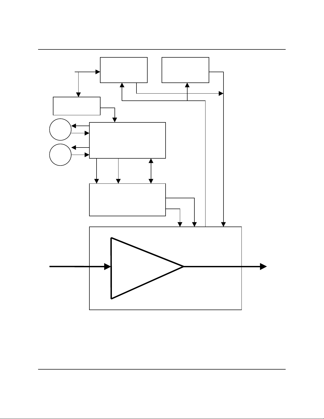
XPA200-7984-I-OPT1, X-Band SSPA Introduction
Prime
Power
Input
PS # 2 28Vdc
FAN1
FAN2
PS #1 10Vdc
PS #2 10Vdc
-5Vdc Interlock
AUX. PS & SWITCH
CONTROL
AS/0206
+12V -12V CONTROL
& MONITOR
MONITOR & CONTROL
-5V
AS/0200
+5V
+10Vdc
RF INPUT RF OUTPUT
POWER
AMPLIFIER
AS/0558
Figure 1.1 FUNCTIONAL BLOCK DIAGRAM
XPA200-7984-I-OPT1, REV.3 1-2
Page 19

XPA200-7984-I-OPT1, X-Band SSPA Introduction
1.3 Specifications
The following are the design, operating and environmental specifications
for the XPA200-7984-I X-Band Solid State High Power Amplifier (SSPA).
Output Front Panel
Frequency 7.900-8.400 GHz Display 24 x 2 LCD
Power 53.0dBm min. @ 1dB Comp. Data Entry Cursor Control Keypad
Mute -80dB Input Sample Type N,50 Ohms,-20dBc
VSWR 1.25:1 Max.
Connector CPR-112G Waveguide Flange
Gain Remote Control
Linear 62dB min, 67dB typ. Comm Port RS-485 or RS-232C
Adjust 20dB in 0.25dB Steps Protocol Comtech ASCII or Emul.
Per 500MHz +
Per 40 MHz +
+0 - +50C +
Third Order Intermod. Tx ON Yellow
Intercept +60.5dBm Min.,+62.0dBm Typ. Online Yellow
Products -30dBc typ., -25dBc max @ Remote Yellow
AM to PM Conversion Height 12.25 inches
2.0 degrees typ., 3.0 max @ rated output Width 19 inches
(see Note 1) Output Sample Type N,50 Ohms,-40dBc
.75dB
.25dB Alarms
0.50dB @ center Freq. Summary Fault Form C
±1.00dB @ full band
3 dB total back off
(two tones,
ªf= 1MHz)
LED
Power Green
Fault Red
Stored Fault Red
Mechanical
Depth 24 inches
Weight 100 lbs.
Group Delay
Linear +
Parabolic +
Ripple 1.0ns Peak-to-Peak (See Note 1)
Spurious 0-100% Noncond. Stor.
Carrier Related -65dBc Shock Normal Commercial
Line Related -50dBc Shipping & Handling
Input
Impedance 50 Ohms Power Requirements
Noise Figure 10dB Typ.,15dB Max. 115 VAC, 47-63 Hz, 2600 VA
VSWR 1.25:1 Max.
Connector Type N
Note 1: P1dB only guaranteed 0 to 40C. Operation above 40C not recommended.
0.03ns/MHZ Environmental
0.003ns/MHz
2
Temperature 0 to +50C Operation
Humidity 10-95% Noncond. Oper.
-40 to +70C Storage
XPA200-7984-I-OPT1, REV.3 1-3
Page 20

XPA200-7984-I-OPT1, X-Band SSPA Introduction
1.4 Prime Power Input
The power input requirements for the XPA200-7984-I X-Band SSPA
are as follows:
! 115 volts AC.
! 47 to 63 Hz.
! 2600 VA (approx. 1800W) nominal
1.5 Physical Dimensions
! Width: 19 inches.
! Height: 12.25 inches.
! Depth: 24 inches.
! Weight: 100 lbs.
1.6 Environmental Specifications
! Temperature: 0 to +50 degrees C operating.
(Note: P1dB guaranteed only 0 to 40C.
Operation above 40C not recommended).
! Humidity: 10 to 95% noncondensing operation.
1.7 Front Panel Controls
The front panel contains a User Interface Key-Pad which is used
by a local operator to input commands to the SSPA. The key-pad
is used to select the configuration for operating and monitoring
the status of the SSPA. In conjunction with the front panel two
line, twenty four character, LCD display, the key-pad allows the
operator to select one of five configurations. The configuration
functions are "Configuration Menu", "Monitor Status Menu",
"Currents Faults Menu", "Stored Faults Menu" and "Utility
Functions Menu".
XPA200-7984-I-OPT1, REV.3 1-4
Page 21

XPA200-7984-I-OPT1, X-Band SSPA Introduction
1.7 Front Panel Controls (Continued)
The key-pad has six keys: Enter, Clear, Right Arrow, Left
Arrow, Up Arrow and Down Arrow. Each key has a logical function:
! Enter Key: (ENT)
Used to select a display function, or to execute a
command to change the configuration of the SSPA.
! Clear Key: (CLR)
Used to cancel a selection, or to cancel a
configuration change which has not been executed
using the "Enter" key. After pressing the "Clear"
key the display will return to the previous
selection.
! Right and Left Arrow Keys:
/
These keys are used to select or change an operating
mode within a function, or to input or change the
configuration input data (numbers).
! Up and Down Arrow Key:
/
These keys are used to move to the next operation
mode, or to move the cursor to select a specific
parameter or digit within an operating mode
selected.
1.8 Front Panel Indicators
There are six LED indicator lights on the front panel which
indicate the status of the SSPA and provide summary fault
information. The indicators are defined as follows:
XPA200-7984-I-OPT1, REV.3 1-5
Page 22

XPA200-7984-I-OPT1, X-Band SSPA Introduction
1.8 Front Panel Indicators (continued)
Faults:
C Fault (Red):
Indicates that a fault condition exists
when the LED light is on.
C Stored Fault (Red):
Indicates that the fault has been logged and
stored When the LED light is on. The fault
may, or may not, be active.
Status:
C Power (Green):
Indicates that power is applied to the
SSPA when the LED light is on.
C Tx ON (Yellow):
Indicates that the transmit function of the
SSPA is on when the LED light is on.
The indicator light reflects the actual
condition of the transmit function.
C On Line (Yellow):
Indicates that the SSPA is operating
on-line to transmit data.
C Remote (Yellow):
Indicates that the SSPA is being
operated in the remote control mode where
commands and data are transferred via an
RS-485 (RS-232C is optional) serial
communications link.
XPA200-7984-I-OPT1, REV.3 1-6
Page 23

XPA200-7984-I-OPT1, X-Band SSPA Introduction
1.9 Front Panel Display
The front panel display is a two line by twenty-four
character, LCD display. Each configuration function, or
operating mode, is shown on the display when the operator enters
a command into the key-pad on the front panel.
1.10 Front Panel Test Point Samples
Two test point connections are located on the front panel
for monitoring the RF input and the RF output. A type N female
connector is provided for the RF sample test points.
1.11 Rear Panel Connections
The following is a list of the connectors on the rear panel:
! Connector J1: SSPA RF Input (RF in).
! Connector J2: SSPA RF Output (RF output).
! Connector J3: AC Prime Power Input (AC in).
! Connector J4: Cust. Discrete Control (Discrete Control).
! Connector J5: Combiner Interface.
! Connector J6: COM1 Port (RS-232C/RS-485) (COM1).
! AC Power On / Off Switch.
XPA200-7984-I-OPT1, REV.3 1-7
Page 24
XPA200-7984-I-OPT1, X-Band SSPA Introduction
1.11.1 RS-485/RS-232C Interface (COM1), Connector J6
The RS-485/RS-232C Interface connector, J6, is a 9 pin "D"
type DB9F connector socket. The pin-out specifications are
contained in Table 1-1. The mating connector is a DB9M.
Table 1-1.
J6, COM1 connector Pin-Out
Pin # RS-232C RS-485 4-Wire RS-485 2-Wire
1 no connect GND; Ground GND; Ground
2 TD; Transmit Data no connect no connect
3 RD; Receive Data no connect no connect
4 no connect +TX; Signal +RX/TX; Signal
5 GND; Ground -TX; Signal
Complement
6 DSR; Unit Ready -
no connect no connect
always high.
7 RTS; Request to
no connect no connect
Send. Looped to
CTS
8 CTS; Clear to
+RX; Signal +RX/TX; Signal
Send
9 no connect -RX; Signal
Complement
-RX/TX; Signal
Complement
-RX/TX; Signal
Complement
XPA200-7984-I-OPT1, REV.3 1-8
Page 25
XPA200-7984-I-OPT1, X-Band SSPA Introduction
1.11.2 Customer Discrete Control, Connector J4
The Customer Discrete Control connector, J4, is a 19 pin
circular connector, type MS3112E14-19S. The pin-out
specifications is contained in Table 1-2. The mating connector
is a MS3116F14-19P.
Table 1-2.
J4, Customer Discrete Control Connector Pin-Out
Pin Signal Name Description
A External Mute
Cmd
B External Mute
External Mute Command. TTL input “high”
mutes the unit.
External Mute Common.
Common
G Local Online
Local Online Status Common.
Common
H Local Online
Tied to pin G when Online, else open.
NO
N Summary Fault
Summary Fault Status Common.
Common
P Summary fault
Open when Faulted, else tied to Pin N.
NO
Note: All other pins are unused.
XPA200-7984-I-OPT1, REV.3 1-9
Page 26
XPA200-7984-I-OPT1, X-Band SSPA Introduction
1.11.3 Combiner Interface, Connector J5
The Redundant Loop interface connector, J5, is a 19 pin
circular connector, type MS3112E14-19S. The pin-out
specifications is contained in Table 1-3 The mating connector is
a MS3116F14-19P.
Table 1-3.
J5, Combiner Interface Connector Pin-Out
Pin # Description Pin # Description
A Inhibit Command L not used
B VPC A+B->Antenna M not used
C not used N not used
D not used P not used
E VPC Output Common R not used
F VPC A(B)->Antenna S Local SumFlt Common
G not used T Local SumFlt NO
H Inhibit Common U not used
J not used V not used
K not used
XPA200-7984-I-OPT1, REV.3 1-10
Page 27
XPA200-7984-I-OPT1, X-Band SSPA Introduction
1.11.4 AC Prime Power Input Connector, J3
The AC prime power input connector, J3, is a 3 pin circular
connector, type CA3102E20-19PB FMLB A. The ground connector, pin
A, is of the first make, last break type. The pin-out
specifications are contained in Table 1-4. A mating connector of
type CA3106E20-19SB is included for the customer.
Table 1-4.
J3, AC Prime Power Input Connector
Pin # Description
A Ground
B Neutral
C Line
1.12 Prime Power Switch
The on/off prime power switch is located on the rear of the
chassis adjacent to the prime power input connector. The circuit
breaker is rated for 40 Amps.
XPA200-7984-I-OPT1, REV.3 1-11
Page 28

Page 29

XPA200-7984-I-OPT1, X-Band SSPA Installation
Section 2
Installation/Operation with
Mitec 2723B
Variable Phase Combiner and
Redundant Switching System
2.1 Unpacking and Inspection
This section is intended to give a brief explanation on how to
setup and operate two Comtech XPA200 SSPAs with the Mitec 2723B
Variable Phase Combiner and Redundant Switching System. More detailed
explanations on operation of the SSPA are contained in later sections
of this manual. More detailed operating instructions for the Mitec
Combiner and redundant switching system can be found in it’s
associated manual.
Inspect the shipping container for damage. The shipping
container and packing materials should be retained for possible reshipment. Check to determine that all parts, materials and
documentation have been shipped with the SSPA. The SSPA should be
inspected for possible damage, and then tested for proper operation.
If the shipment is incomplete, or there is mechanical damage, or
the SSPA does not operate properly, notify the COMTECH Customer
Service representative immediately. If there is damage to the
shipping container, notify the carrier, and retain all shipping
materials for inspection by the carrier.
2.2 Rack Mount Installation
2.2.1 XPA200 Installation
The XPA200-7984-I X-Band SSPA is designed for installation to
mount in a standard 19 inch rack cabinet or enclosure. The SSPA
chassis requires 12.25 (7RU) inches of panel height space.
Adequate air ventilation should be provided to the rack
mounted equipment. Cool air is taken in through the front panel and
XPA200-7984-I-OPT1, Rev.2 2-1
Page 30

XPA200-7984-I-OPT1, X-Band SSPA Installation
exhausted out the rear panel. Locate the unit so the input and
output airflow paths are not obstructed or restricted. This will
minimize the amplifier operating temperature, and provide years of
reliable operation.
If the SSPA is to be mounted on slides, the slides must be the
COMTECH rack slides provided with the SSPA. Mount the slides on the
sides of the SSPA chassis with the mounting hardware provided.
Then, install the slide rails in the rack cabinet enclosure.
Secure the SSPA to the rack cabinet with four screws inserted
through the SSPA front panel slotted holes.
2.2.2 Combined/Redundant Amplifier Installation and Cabling
For the complete combined/redundant amplifier system, it is
most common to install the Mitec 2723B combiner in the top position
of the rack, followed by SSPA B, with SSPA A in the bottom position.
(See the outline drawing at the end of this section.)
Connect the Comtech supplied inter-unit control cable,
CA/8981, between the Mitec Combiner ports P1,P2,P3 and to each J5 of
SSPA A and SSPA B as indicated by the labels on the cable. (Note
that this cable is setup for the bottom SSPA be SSPA A.)
Attach the supplied waveguide termination to the load port of
the Mitec 2723B such that the termination resides above the unit.
(See outline drawing.)
Attach user supplied coaxial cables and waveguide between the
Mitec 2723B and each XPA200. Refer to Figure 2.3 of the Mitec
manual. A waveguide pressure window has also been supplied and can
be attached according to customer preference.
(Note that CA/8981 has been constructed for SSPA A to be in the
bottom position. The coaxial cables and waveguides should be
connected accordingly. In case of conflict, it will be necessary to
modify either CA/8981 or the coaxial cables and waveguides.)
CAUTION!
Before applying AC power to the units, make sure the waveguide
output of the amplifiers and the antenna and load ports of the
combiner are properly terminated. Failure to do so could lead to
equipment damage and excessive RF radiation levels.
Attach power cords to the units. Two standard power cords are
supplied with the Mitec 2723B. Each XPA200 is supplied with a
mating connector to enable the user to fabricate a power cord. See
sections 1.4 and 1.11.4.
XPA200-7984-I-OPT1, Rev.2 2-2
Page 31

XPA200-7984-I-OPT1, X-Band SSPA Installation
2.2.3 Some Notes on Establishing Remote Communications
1. The Mitec 2723B combiner was set at the Comtech factory to
RS-232 operation per customer request, on address 00 (30H)
through P4. However, the Mitec 2723B has a non-standard pin-
out on this I/O connector. Connections should be made as
shown below:
Common PC 9-Pin Serial Port
Mitec 2723B Remote Serial Access
Port, P4 (9-pin)
Pin 2 (Rd) Pin 3
Pin 3 (Td) Pin 4
Pin 5 (Gnd) Pin 5
Table 2.1 Typical RS-232 Connection to Mitec P4
2. Physical remote cabling information for each Comtech SSPA
is described in section 5.3 of this manual. It is recommended to
set SSPA A to address 001 and SSPA B to address 002. These and
other communication parameters can be set via the front panel of
each SSPA, as described in section 3 and section 5.
3. A special Windows-compatible program has been included on
a floppy disk in this manual to assist in communicating with the
Combined/Redundant Amplifier system. Refer to the file “Notes.txt”
for operating instructions.
XPA200-7984-I-OPT1, Rev.2 2-3
Page 32

XPA200-7984-I-OPT1, X-Band SSPA Installation
2.3 Notes on Combined/Redundant System Operation and Setup
The following paragraphs are intended to give a brief explanation
of system operation of the Comtech XPA200 SSPAs with the Mitec 2723
Variable Phase Combining and Redundant Switching System. More
detailed information can be found in each unit’s respective operating
manual. A review of the operation of a Variable Phase Combiner is
shown in Table 2.2 below.
(Note: The Load Overheat function mentioned in the Mitec 2723B manual
is not operational. The Mitec factory explained that this was an
option for another project that is not available to Comtech. However,
this should not cause any concern because the load is rated for 1000W
(convection cooling) and the maximum power possible into the load is
approximately 525W.)
VPC
Function
VPC
Pos.
Applied
Power
Power Observed
at Load
(less I.L.)
Power Observed
at Antenna
(less I.L.)
A to Antenna 1 A and B Full Power of B Full Power of A
A only Half Power of A Half Power of A
B only Half Power of B Half Power of B
A + B to
Antenna
2
A & B not
phase
adjusted
A & B phase
adjusted*
Partial Power of
A & B
Negligible Power
Partial Power
of A & B
Full Combined
Power of A & B
B to Antenna 3 A and B Full Power of A Full Power of B
A only Half Power of A Half Power of A
B only Half Power of B Half Power of B
A + B to
Load
4
A & B not
phase
adjusted
Partial Power of
A & B
Partial Power
of A & B
A & B phase
adjusted*
Full Combined
Power of A & B
Negligible Power
* A & B must have equal carrier magnitude and frequency.
Table 2.2 Variable Phase Combiner Operation
XPA200-7984-I-OPT1, Rev.2 2-4
Page 33

XPA200-7984-I-OPT1, X-Band SSPA Installation
2.3.1 Redundant Operation and Setup
The system can operate in a standard 1:1 redundant
configuration by choosing VPC position 1 (SSPA A to antenna) or 3
(SSPA B to antenna) on the Mitec 2723B. For example, if the Mitec
2723B was set to run in Automatic mode and SSPA A was normally
operating to the antenna (VPC position 1), a fault on SSPA A would
cause the system to immediately switch to postion 3, or SSPA B to
antenna.
Each SSPA may have slightly different gain values. A
procedure to equalize gain and output power between SSPA A and SSPA
B for redundancy operation is described below. The output powers
from SSPAs A and B are first equalized by measurements at the load
port before switching power to the antenna port.
A. To set the output power of SSPA A:
1. Mute SSPA B via remote or front panel controls.(To
prevent unwanted power from SSPA B going to antenna.)
2. Set VPC to position 3 (B to antenna, A to load).
3. Connect a power meter to the Mitec calibrated load
measuring port (see 2723B test data for exact calibration
data). Adjust output power of SSPA A to desired level by
adjusting input RF power or by using the SSPA A attenuation
setting.
B. To set the output power of SSPA B:
1. Mute SSPA A via remote or front panel controls.(To
prevent unwanted power from SSPA A going to antenna.)
2. Set VPC to position 1 (A to antenna, B to load).
3. Connect a power meter to the Mitec calibrated load
measuring port (see 2723B test data for exact calibration
data). Adjust output power of SSPA B to desired level
(usually the same as A) by adjusting input RF power or by
using the SSPA B attenuation setting.
C. Choose the unit desired to be on-line.
1. Mute both units to prevent unwanted power from going to
the antenna.
2. Choose SSPA A (position 1) or SSPA B (position 3) for
operation to the antenna. The other unit will be sent to
the load.
3. Set the Mitec unit in Automatic mode and un-mute the
SSPAs.
4. Verify proper output power going to antenna by
connecting a power meter to the Mitec Antenna Forward
power
measuring port (see Mitec test data for calibration factor).
XPA200-7984-I-OPT1, Rev.2 2-5
Page 34

XPA200-7984-I-OPT1, X-Band SSPA Installation
2.3.2 Combined (SSPA A and SSPA B) Operation and Setup
The full powers of SSPAs A and B can be phase combined for
increased system power output. Maximum output is obtained only if
the signals of SSPA A and B have equal or close carrier magnitude
and frequency, and the relative phase between them is adjusted.
Phase adjustment of the input signals for maximum output power is
accomplished via the screw adjustment on the front panel of the
Mitec 2723B.
A procedure to maximize output power by phase combining the
outputs of SSPA A and B is given below. The procedure first
optimizes the power off-line by using the load port, and then
switches the maximized power on-line through the antenna port.
(Note of Caution: During the phase adjustment period, it is possible
to send a significant signal level to the antenna port even though
the combiner is directed to the load. Therefore, it is recommended
to perform the phase combining adjustment at low power levels or
activate any maintenance switches which may keep unwanted signal
from the actual antenna.)
1. Connect a power meter to the Mitec calibrated load measuring
port (see 2723B test data for exact calibration data).
2. Select VPC position 1, (A to Antenna, B to Load). Adjust
SSPA B input signal level and attenuation to achieve desired
output power level from SSPA B. For example, 40.0 dBm.
3. Select VPC position 3, (B to Antenna, A to Load). Adjust
SSPA A input signal level and attenuation to achieve an output
power level within +/- .3 dB of that obtained from SSPA B in step
2 above. (It may be necessary to repeat step 2 and increase
attenuation level of SSPA B if SSPA B has more gain than SSPA A.)
4. Select VPC position 4, A&B to load. Adjust the phase trimmer
on the Mitec 2723B front panel until maximum power is reached,
typically 2.7-2.95 dB above the single unit output power level.
For this example, 42.7-42.95.
5. Select VPC position 2, A&B to load, to go on-line and route
power to the antenna port.
6. Monitor the output power through the Antenna Forward
measuring port on the Mitec unit (see 2723B test data for exact
calibration data). Perform any minor trimming of the phase
shifter to maximize output power.
7. Note: Whenever a significant change in signal frequency
occurs, it will be necessary to re-adjust the phase shifter.
XPA200-7984-I-OPT1, Rev.2 2-6
Page 35
Page 36

Page 37

XPA200-7984-I-OPT1, X-Band SSPA System Operation
Section 3
System Operation
3.1 General
This section contains instructions for operating the solid state
high power amplifier (SSPA). The front panel of the SSPA has a keypad for operator input commands, an LCD Display, LED status
indicators, and connector test sample ports to monitor the RF input
and output signals. Table 3-1 is provided to show the control and
operating functions of the SSPA.
3.2 Switching Power On
Before turning the Prime Power Switch to the "on" position, check
to ensure that the installation is complete, and verify that the SSPA
is connected to the proper prime power source, RF input and RF output.
Switch the ON/OFF Prime Power Switch on the rear panel to ON.
Verify that the cooling fans are operating, and that the POWER ON LED
STATUS indicator light is on.
After the prime power is switched on, the STATUS indicators
should be as follows:
! POWER ON: Indicator ON.
! TRANSMIT: Indicator OFF.
! REMOTE: Indicator ON.
! ON LINE: Indicator ON.
! FAULT: Indicator OFF.
! STORED FAULT: Indicator OFF.
After the AC power is switched on and before pressing the buttons
on the key-pad, the LCD display message should be similar to:
XPA200-7984-I
SW VER X.XX SN7984XXXX
XPA200-7984-I-OPT1, Rev.2 3-1
Page 38

XPA200-7984-I-OPT1, X-Band SSPA System Operation
Table 3-1. Operating Functions - Front Panel
Item Functional Description Reference
Designation
Key-Pad;
ENT key
Key-Pad;
CLR key
Key-Pad;
Right Arrow key
Key-Pad;
Left Arrow key
Key-Pad;
Up Arrow key
Key-Pad;
Down Arrow key
LCD Display Displays commands and data entered
STATUS Indicator,
Green
STATUS Indicator,
yellow
STATUS Indicator,
yellow
Enters commands into the
converter.
Clears commands and data selected
and not entered.
Selects functions and the menu
operating data.
Selects functions and the menu
operating data.
Selects the operating menu and
data values.
Selects the operating menu and
data values.
into the key-pad.
Prime power is applied when the
light is on.
Transmit function operating when
the light is on.
In Remote Control Mode when the
light is on.
ENT
CLR
Right Arrow
Left Arrow
Up Arrow
Down Arrow
POWER ON
TRANSMIT ON
REMOTE
STATUS Indicator,
yellow
STATUS Indicator,
Red
STATUS Indicator,
Red
INPUT SAMPLE Type N connector test point
OUTPUT SAMPLE Type N connector test point to
XPA200-7984-I-OPT1, Rev.2 3-2
Operating on-line to receive
data when the light is on.
Fault condition exists when the
light is on.
Faults stored and logged
when the light is on.
to sample RF input.
sample RF output.
ON LINE
FAULT
STORED
FAULT
SAMPLE INPUT
SAMPLE OUTPUT
Page 39

XPA200-7984-I-OPT1, X-Band SSPA System Operation
3.3 Operation
Local operation of the 200 watt, X-Band SSPA is controlled by
operator input commands initiated through the six button key-pad on
the front panel. The key-pad is the local operator's interface to
control, configure and monitor the status of the SSPA. Operator
inputs and commands entered into the key-pad are displayed by the
front panel twenty-four character, two line, LCD display. See Section
5.0 for Remote Control Operation.
There are five operating command functions: Configuration,
Monitor Status, Currents Faults, Stored Faults and Utility Functions.
A flow chart for selecting the commands, operating menus, and data
inputs is shown in Figures 3-1 through 3-6.
---------
CONFIGURATION-MENU
----
(See Figure 3-2)
---------
MONITOR-STATUS-MENU
--
(See Figure 3-3)
---------
CURRENT-FAULTS-MENU
--
(See Figure 3-4)
ENTER
SELECT
SELECT
SELECT
---------
--
---------
---------
XPA200-7984-I
----
SW VER 1.02 SNXXX
---
---
-----
LEGEND
KEY-PAD
DISPLAY
---------
---
---------
UTILITY-FUNCTIONS-MENU
-
SELECT
STORED-FAULTS-MENU
---------
(See Figure 3-5)
SELECT
---------
(See Figure 3-6)
UP
DOWN
------------------------
------------------------
-
RIGHT
LEFT
ENTER
CLR
Figure 3-1. SSPA Operating Command Functions
XPA200-7984-I-OPT1, Rev.2 3-3
Page 40
XPA200-7984-I-OPT1, X-Band SSPA System Operation
UP
------ SELECT ------
-- CONFIGURATION MENU
ATTENUATION-=-10.00-dB
AMPLIFIER=-ON--MUTE=-OFF
(See Para. 3.3.2.1)
-
------------------------
(See Para. 3.3.2.2)
FAULT RECOVERY:MANUAL
---------------------
(See Para. 3.3.2.3)
(See Para. 3.3.2)
ENTER
ENTRY MODE -= REMOTE
DOWN
--
-
LEGEND
RIGHT
UP
ENTER
KEY-PAD
DISPLAY
DOWN
---------------------
---------------------
LEFT
CLR
Figure 3-2. Configuration Menu Commands.
XPA200-7984-I-OPT1, Rev.2 3-4
Page 41
XPA200-7984-I-OPT1, X-Band SSPA System Operation
UP
---------SELECT---------
--MONITOR-STATUS-MENU---
ENTER
+12V=+12.2-----12V=-12.0
--VCC=4.9------5V=-4.9--
----28-VDC-PS-=-27.9----
10VPS1=10.3 10VPS2=10.3
--AMPLIFIER-TEMP=+44C---
------------------------
(See Para. 3.3.3)
DOWN
-RF-FET----Q3-=-X.X-AMPS
-RF-FET----Q4-=-X.X-AMPS
-RF-FET----Q5-=-X.X-AMPS
-RF-FET----Q6-=-X.X-AMPS
-RF-FET----QX-=-X.X-AMPS
-RF-FET----QX-=-X.X-AMPS
-RF-FET----Q18=-X.X-AMPS
-RF-FET----Q19=-X.X-AMPS
FORWARD-RF-PWR:- 53.0-DBM
REVERSE-RF-PWR:-<26.2-DBM
LEGEND
RIGHT
UP
ENTER
KEY-PAD
--RF-FET----Q1-=-XXXmA--
--RF-FET----Q2-=-XXXmA--
DISPLAY
DOWN
------------------------
------------------------
LEFT
CLR
Figure 3-3. Monitor Status Menu Commands
XPA200-7984-I-OPT1, Rev.2 3-5
Page 42

XPA200-7984-I-OPT1, X-Band SSPA System Operation
UP
---------SELECT---------
--CURRENT-FAULTS-MENU---
ENTER
POWER-FAULTS:----+12V=OK
-12V=OK--VCC=OK---5V=OK-
(See Para. 3.3.4.1)
-----28-VDC-PS-=-OK-----
--10VPS1=OK--10VPS2=OK--
(See Para. 3.3.4.1)
(See Para. 3.3.4)
DOWN
---AMPLIFIER-TEMP-=-OK--
-FAN-1-=-OK--FAN-2-=-OK-
(See Para. 3.3.4.2,
Para. 3.3.4.3)
--M&C-PROCESSORS-=-OK---
------------------------
(See Para. 3.3.4.3)
LEGEND
KEY-PAD
DISPLAY
RIGHT
UP
DOWN
------------------------
------------------------
LEFT
ENTER
CLR
Figure 3-4. Currents Faults Menu Commands
XPA200-7984-I-OPT1, Rev.2 3-6
Page 43

XPA200-7984-I-OPT1, X-Band SSPA System Operation
UP
---------SELECT---------
---STORED-FAULTS-MENU---
ENTER
TOTAL-FAULTS-STORED:--XX
LAST-19:20:05---02/15/95
(See Para. 3.3.5.1)
----CLEAR-ALL-STORED----
------FAULTS?-NO--------
(See Para. 3.3.5)
DOWN
(See Para. 3.3.5.2)
LEGEND
RIGHT
UP
ST-FAULT-XX-----19:20:05
KEY-PAD
DOWN
LEFT
OK-FINE-LOCK----02/15/95
------------------------
(See Para. 3.3.5.3)
DISPLAY
------------------------
Figure 3-5. Stored Faults Menu Command
XPA200-7984-I-OPT1, Rev.2 3-7
ENTER
CLR
Page 44

XPA200-7984-I-OPT1, X-Band SSPA System Operation
UP
---------SELECT---------
--UTILITY-FUNCTIONS-MENU---
ENTER
----TIME:- 10:20:05AM----
-----DATE--09/15/94------
---SERIAL-MODE=RS232C--ADDR=XXX-BAUD=YYYY-P=ZZ-
SERIAL-PORT-DATA-FORMAT=
-7-DATA,-2-STOP,-PARITY-
(See Para. 3.3.6)
DOWN
FORWARD -RF-POWER-MONITOR
----OFFSET-=-+0.0dBm----
REVERSE-RF-POWER-MONITOR
----OFFSET-=-+0.0dBm----
--------LAMP-TEST-------
----------OFF-----------
LEGEND
KEY-PAD
DOWN
UP
RIGHT
LEFT
ENTER
CLR
-DISPLAY-CONTRAST-=XX-DISPLAY-BRIGHTNESS-=-XX-
DISPLAY
------------------------
------------------------
Figure 3-6. Utility Functions Menu Commands
XPA200-7984-I-OPT1, Rev.2 3-8
Page 45

XPA200-7984-I-OPT1, X-Band SSPA System Operation
3.3.1 SSPA commands
The SSPA commands are in a tree structured menu format
designed for access and execution of all control functions, and
to prevent the execution of an invalid entry by the operator.
When the prime power is turned on, the LCD display will contain a
message indicating the SSPA model number and the version number
of the firmware installed in the SSPA.
To select a Command Function press the "ENT" button on the
key-pad. The LCD display will indicate:
SELECT
CONFIGURATION MENU
This will provide the local operator access to the Command
Function Menus, which is the top level structure to start the
selection of Command Function Menus to input into the SSPA. To
sequence to the next Command Function Menu press a "DOWN" or "UP"
arrow button on the key-pad. The SSPA will step to the next
Command Function Menu each time a "DOWN" or "UP" arrow button is
pressed. The current Command Function Menu will be displayed on
the LCD display. The Command Function Menus are shown in Figure
3-1.
To select a specific Command Function Menu press the "ENT"
key-pad button. If a function is selected in error, press the
clear ("CLR") button which will return the SSPA to the main
command menus to allow the selection of another function. Any
one of the five Command Function Menus can be selected using this
procedure.
Once a Command Function has been selected, use the "RIGHT"
or "LEFT" arrow key-pad buttons to sequence through the Operating
Mode Commands. Each of the modes will be displayed on the LCD
display. A specific operating mode is selected by pressing the
"ENT" button. If an mode is selected in error, press the clear
("CLR") button which will return the SSPA to the operating menus
to allow the selection of another mode.
XPA200-7984-I-OPT1, Rev.2 3-9
Page 46

XPA200-7984-I-OPT1, X-Band SSPA System Operation
3.3.1 SSPA Commands (cont.)
When an operating mode is selected, a parameter or a digit
within the parameter will be flashing on the LCD display. Use
the "RIGHT" and "LEFT" arrows buttons to sequence through the
parameters or digits to select the next parameter or digit. A
specific parameter or value is selected by pressing the "ENT"
button. If a parameter or value is selected in error, press the
clear ("CLR") button which will return the SSPA to the original
parameter or value to allow another selection.
After selecting a parameter or digit, use the "UP" or "DOWN"
arrow buttons to select the next parameter, or to increment or
decrement the value of a digit. A specific new parameter or new
value is selected by pressing the "ENT" button. If a parameter
or value is selected in error, press the clear ("CLR") button
which will return the SSPA to the original parameter or value to
allow another selection.
Each time the clear ("CLR") button is pressed, the SSPA will
return to the menu level prior to the last "ENT" command.
3.3.2 Configuration Menu
The Configuration Functions are as follows:
3.3.2.1 Frequency Operating Mode
Attenuation (ATTN):
Input and displays the SSPA attenuation setting which
is selected between 0.00 to 20.00 in 0.25 dB steps.
The default setting is 10.00 dB.
Amplifier: Control supply voltage to RF FETS. The
default mode is ON.
Mute: Provide SSPA mute control. The default is OFF.
Other possible modes are:
INH inhibited or muted by the Mitec 2723B
EXT mute on from external J4 control (see
section 1).
XPA200-7984-I-OPT1, Rev.2 3-10
Page 47

XPA200-7984-I-OPT1, X-Band SSPA System Operation
3.3.2.2 Entry Mode
Mode: The entry mode is Local or Remote. The default
is Local.
3.3.2.3 Fault Recovery: Fault Recovery is Manual or Auto. The
default is Auto.
3.3.3 Monitor Status Menu
Monitors and displays the status of:
! All SSPA power supplies.
! SSPA internal temperature.
! RF output power level.
! RF FET currents (Q1 through Q19).
3.3.4 Current Faults Menu
Displays the status of the current fault conditions. The
LCD display will indicate "FT" when a fault condition exists.
The display will indicate "OK" when a fault has not occurred.
3.3.4.1 Power Faults
Displays the DC voltage power supply faults. The DC
voltages displayed are:
! +12 VDC.
! -12 VDC.
! VCC.
! -5 VDC.
! +28 VDC
! +10 VDC, PS1 and PS2
XPA200-7984-I-OPT1, Rev.2 3-11
Page 48

XPA200-7984-I-OPT1, X-Band SSPA System Operation
3.3.4.2 SSPA Over Temperature Fault
Displays a SSPA temperature fault condition.
3.3.4.3 Fan Faults
Displays status of both FAN #1 and FAN #2.
3.3.5 Stored Faults Menu
The SSPA displays a total of one hundred (100) faults which
a date and time stamped and stored in memory as they occur. The
stored faults remain in memory until a clear command is entered.
3.3.5.1 Total Stored Faults
Displayed the total number of faults stored. The most
recent fault stored is displayed on the LCD display.
3.3.5.2 Clear All Stored Faults
Input command to clear all faults. The command is
"YES" or “NO” which is displayed on the LCD display.
3.3.5.3 Display Stored Fault
The local operator can sequence through the stored
faults starting with the most recent fault. The Fault
number, time, description and date is displayed on the
LCD display.
XPA200-7984-I-OPT1, Rev.2 3-12
Page 49

XPA200-7984-I-OPT1, X-Band SSPA System Operation
3.3.6 Utility Menu
The local operator can input commands to the following
Utility Functions which are displayed on the LCD display:
! TIME. Military time is used in hours, minutes and
seconds.
! DATE. The date is displayed in month, day and year.
! Serial MODE (communications link).
C RS-232C, RS-485-2, RS-485-4.
C Physical Address. The default address starts from
one (001).
C BAUD (Rate). The default baud rate is 9600.
! SERIAL PORT DATA FORMAT. The default is 7 Data, 2 Stop
Bits, with Parity. An optional format is 8 Data, 1 Stop
Bit, with No Parity. This can only be changed via the
front panel menu system.
! DISPLAY CONTRAST. The default is 15, with values from
zero (0) to thirty (30).
! DISPLAY BRIGHTNESS. The default is 15, with values
from zero (0) to thirty (30).
! FORWARD RF POWER MONITOR OFFSET. This function allows
the operator to calibrate (fine tune) the RF Power
Monitor for a specific carrier frequency. The RF Power
Monitor is calibrated in the factory at the SSPA center
frequency. The operator can adjust (offset) the
display level using this function. The range equals
-6.0 to +6.0 dBm in 0.1 dBm steps.
! REVERSE RF POWER MONITOR OFFSET. This function allows
the operator to calibrate (fine tune) the RF Power
Monitor for a specific carrier frequency. The RF Power
Monitor is calibrated in the factory at the SSPA center
frequency. The operator can adjust (offset) the
display level using this function. The range equals
-6.0 to +6.0 dBm in 0.1 dBm steps.
! LAMP TEST. The default is OFF
XPA200-7984-I-OPT1, Rev.2 3-13
Page 50

Page 51

XPA200-7984-I-OPT1, X-Band SSPA Redundant System Operation
Section 4
Redundant System Operation
4.1 GENERAL
This option or application uses a Mitec variable phase
combiner for redundany use which is totally different than the
standard Comtech Communications redundancy operating features.
Section 2 contains the specialized redundancy system
features for this option. Also see the Mitec 2723B manual for
more detailed information.
XPA200-7984-I-OPT1, Rev.2 4-1
Page 52

Page 53

XPA200-7984-I-OPT1, X-Band SSPA Remote Control
Chapter 5
Remote Control
5.1 GENERAL
Each COMTECH X-Band SSPA can be remotely controlled through a
serial port. COMTECH’s simplified Command/Response protocol is
easily invoked by either a monitor and control computer, a nonintelligent ASCII terminal or a laptop computer operating in
terminal emulation mode. All SSPA configuration parameters as well
as all monitor and status information is available via the remote
port.
5.2 ELECTRICAL INTERFACE
The remote control interface supports either 2-wire RS-485,
4-wire RS-485 or RS-232C. The default port is 2-wire RS-485.
Selection of the interface type is made via front panel menu
selection.
5.2.1 RS-232C
Levels, pulse shapes and impedances conform to EIA standards
for asynchronous operation.
5.2.2 RS-485
Levels, pulse shapes and impedances conform to EIA
standards.
5.3 PHYSICAL INTERFACE
All three interface types (2-wire RS-485, 4-wire RS-485 and
RS-232C) are implemented alternately through the same 9-pin
connector.
XPA200-7984-I-OPT1, Rev.2 5-1
Page 54

XPA200-7984-I-OPT1, X-Band SSPA Remote Control
5.3.1 Connector
The remote control port is a female DB-9 connector located
on the rear of the SSPA.
5.3.2 Pin-out
5.3.2.1 RS-232C
PIN NAME FUNCTION
2 TD SSPA Transmit Data
3 RD SSPA Receive Data
5 GND Ground
6 DSR Unit Ready. Always high.
7 RTS Request to Send. Looped to CTS.
8 CTS Clear to Send
It should be noted that Comtech SSPA’s do not require the
hardware handshaking provided by the DSR, RTS and CTS signals.
These signals are provided for customers who are using interface
terminals that require this handshaking. Most of today’s PC’s
are provided with RS-232C serial ports that do not require the
hardware handshaking. In these instances, the interface can be
reduced to three (3) signals; TD, RD and GND.
5.3.2.2 RS-485
Both 2-wire and 4-wire applications are supported. The 4-wire
interface provides independent signal wires for each of the receive
(+RX) signal and its complement (-RX) as well as the transmit (+TX)
signal and its complement (-TX). In the 2-wire interface, the
receive signal and the transmit signal (+RX/TX) share one wire and
likewise the complement signals (-RX/TX) share one wire. Choice of
2-wire versus 4-wire is based on the customers interface equipment
and the cabling between this equipment and the SSPA(s).
XPA200-7984-I-OPT1, Rev.2 5-2
Page 55

XPA200-7984-I-OPT1, X-Band SSPA Remote Control
5.3.2.2.1 RS-485 2-wire
The pinout for the 2-wire interface is provided below. Note
that each signal pair (+RX/TX and -RX/TX) is provided on two
pins. This is done to provide customers who are using ‘soldercup’ type DB-9 connector the ability to more easily daisy chain
the signals to multiple devices while maintaining one wire per
‘solder-cup’. Customers who use ‘IDC Mass Terminated’ style DB-9
connectors (Ribbon cable types) need only use three (3) signals.
PIN NAME FUNCTION
1 GND Ground
4 +RX/TX Signal Loop In
5 -RX/TX Signal Complement Loop In
8 +RX/TX Signal Loop Out
9 -RX/TX Signal Complement Loop Out
5.3.2.2.2 RS-485 4-wire
The pinout for the 2-wire interface is provided below. Note
that all five (5) signals are required.
PIN NAME FUNCTION
1 GND Ground
4 +TX Transmit Signal
5 -TX Transmit Signal Complement
8 +RX Receive Signal
9 -RX Receive Signal Complement
5.3.3 Cables
5.3.3.1 RS-232
The remote control port is configured with pin 2 as the
transmit data signal (TD) and pin 3 as the receive data signal.
This arrangement allows straight connection (pin 2 to pin 2 and
pin 3 to pin 3) between the SSPA and most standard serial ports
using any standard RS-232C cable (i.e. no need to swap pins 2 and
3).
XPA200-7984-I-OPT1, Rev.2 5-3
Page 56

XPA200-7984-I-OPT1, X-Band SSPA Remote Control
5.3.3.2 RS-485
RS-485 cabling can be implemented with a single ribbon cable
using ‘IDC Mass Terminated’ style connectors or with discrete
wires using ‘solder-cup’ style connectors. A sufficient length
of ribbon cable must be allowed to reach the system monitor and
control computer.
5.4 PROTOCOL
5.4.1 Transmission Mode
The transmission mode is half duplex implemented in
Command/Response convention. This method requires the external
system monitor and control unit to initiate all communications by
command and the SSPA to respond with either confirmation or an
error message. The confirmation may contain status information.
5.4.2 Baud Rate
The default serial port Baud Rate is 9600. Baud rates of
4800, 2400, and 1200 and 300 are also supported.
5.4.3 Format
The following parameters are the default character format.
1 Start Bit
7 Data Bits
2 Stop Bits
1 Parity Bit
An optional character format that can be selected is:
This can only be selected from the Front Panel Menu.
1 Start Bit
8 Data Bits
1 Stop Bit
0 Parity Bits
5.4.4 Character Set
The character set implemented is ASCII.
XPA200-7984-I-OPT1, Rev.2 5-4
Page 57

XPA200-7984-I-OPT1, X-Band SSPA Remote Control Remote Control
5.4.5 Response Timeout
A minimum of 500 milliseconds should be provided before
declaring a ‘no reponse’ instance, at which time the command
should be re-transmitted.
5.4.6 Bus Inactivity Requirement
COMTECH recommends that a minimum of 50 milliseconds bus
inactivity be provided by the user between the receipt of a
response from an addressed SSPA and issuing the next command on
the serial bus.
5.5. ACCESS METHODS
SSPAs may be directly accessed by the RS-232C interface or
by the RS-485 interface in a buss configuration.
5.5.1 RS-485
In this control network, the SSPA is paralleled on a common
RS-485 cable, and has a unique physical address. Only one RS-485
port is required on the system's monitor and control computer.
5.5.2 RS-232C
For RS-232C control, a direct RS-232C cable connection is
made to each SSPA to be accessed. If an external Monitor and
Control Computer is used, one RS-232 port per SSPA is required.
5.6 ADDRESSES
All SSPAs are addressed in a command by the Device Address.
The Device Address consists of a physical address or a physical
address plus a virtual address.
5.6.1 Physical Address
Each SSPA in the system must have a unique physical address.
The physical address consists of a string of 1, 2 or 3 numbers
from 1 to 256. The physical address is entered into a SSPA via
the front panel.
Example: 10 Addresses SSPA whose physical
XPA200-7984-I-OPT1, Rev.2
address is 10.
5-5
Page 58

XPA200-7984-I-OPT1, X-Band SSPA Remote Control Remote Control
5.7 Message Structure
The structure of either a Command , Response or Error
Message is as follows:
Start Character
Device Address
Command or Response
End of Message String
5.7.1 Start Character
The Start Character begins each message:
Example: < Start of a user Command.
> Start of a SSPA response.
5.7.2 Device Address
The Device Address consists of a Physical Address. For this
document DEV is used for the generic case examples.
Example: <10 direct addressing
5.7.3 Command
A Command is a variable length character string beginning
with a / and containing either an instruction or an instruction
and data for a SSPA to act upon. If data is passed by command it
is appended to the instruction by an underscore( _ ). If data is
retrieved by command underscore follows the instruction flagging
the SSPA to supply data in a response. In this document /COM is
used for the generic case examples.
Example: <DEV/COM_xxx'cr' Sends data to a SSPA.
Example: <DEV/COM_'cr' Requests information from
a SSPA.
5.7.4 Confirmation Response
A confirmation will change the start character, and echo the
Device Address and Command. Any requested data will be appended
XPA200-7984-I-OPT1, Rev.2
5-6
Page 59

XPA200-7984-I-OPT1, X-Band SSPA Remote Control Remote Control
to the Command.
Example: >DEV/COM_xxx'cr''lf']
5.7.5 Error Response
If a SSPA cannot execute a Command or detects a protocol
violation, an error response is generated. An error is flagged
by changing the "/" command designator in the response to a "?".
Following the "?" error symbol are two characters which are
unique error symbols useful for computer analysis. The two error
symbols are followed by a text string explaining the error for
the convenience of a human operator. For this document ER is
used for the generic case examples response.
Example: >DEV?COM ER Error Message 'cr''lf']
5.7.6 End Of Message
End of message strings were devised in such a way that an
orderly screen presentation would result when SSPAs are
controlled by simple ASCII terminals.
5.7.6.1 Command Ending
The end of message for a command is a carriage return. For
this document 'cr' is used for the carriage return.
Example: <DEV/COM'cr'
5.7.6.2 Response Ending
End of message for a response is a carriage return, line
feed and a bracket: 'cr''lf'].
Example: >DEV/COM'cr''lf']
XPA200-7984-I-OPT1, Rev.2
5-7
Page 60

XPA200-7984-I-OPT1, X-Band SSPA Remote Control Remote Control
5.8 COMMAND/RESPONSE PAIRS
5.8.1 Utility Commands
5.8.1.1 Time
Set Time: <DEV/TIM_hh:mm:ss'cr' hh = Hour*
Confirmation: >DEV/TIM_hh:mm:ss'cr''lf'] mm = Minutes
ss = Seconds
Retrieve Time: <DEV/TIM_'cr'
Confirmation: >DEV/TIM_hh:mm:ss'cr''lf']
* Note: 24 hour military time is used.
5.8.1.2 Date
Set Date: <DEV/DAT_mm/dd/yy'cr' mm = Month
Confirmation: >DEV/DAT_mm/dd/yy'cr'lf'] dd = Day
yy = Year
Retrieve Date: <DEV/DAT_'cr'
Confirmation: >DEV/DAT_mm/dd/yy'cr''lf']
5.8.1.3 Physical Address
The default Physical Address from is 1.
Set Physical Address: <DEV/SPA_xxx'cr' xxx = 1 to 255
Confirmation: >DEV/SPA_xxx'cr''lf']
Retrieve Phys. Addr: <DEV/SPA_'cr'
Confirmation: >DEV/SPA_xxx'cr''lf']
5.8.1.4 Baud Rate
The default baud rate is 9600.
Set Baud Rate: <DEV/SBR_xxxx'cr' xxxx = 300,
Confirmation: >DEV/SBR_xxxx'cr''lf'] 1200, 2400,
Retrieve Baud Rate: <DEV/SBR_xxxx'cr'
Confirmation: >DEV/SBR_xxxx'cr''lf']
4800 or 9600
XPA200-7984-I-OPT1, Rev.2
5-8
Page 61

XPA200-7984-I-OPT1, X-Band SSPA Remote Control Remote Control
5.8.1.5 Parity Bit
The default parity is even.
Set Parity Bit: <DEV/SPB_xxxx'cr' xxxx = ODD
Confirmation: >DEV/SPB_xxxx'cr''lf'] or EVEN
Retrieve Parity Bit: <DEV/SPB_'cr'
Confirmation: >DEV/SPB_xxxx'cr''lf']
5.8.1.6 LCD Contrast
The default is 15.
Set Contrast: <DEV/CON_xx'cr' xx = 0 to 30
Confirmation: >DEV/CON_xx'cr''lf']
Retrieve Contrast: <DEV/CON_'cr'
Confirmation: >DEV/CON_xx'cr''lf']
5.8.1.7 LCD Brightness
The default is 15.
Set Brightness: <DEV/LCD_xx'cr' xx = 0 to 30
Confirmation: >DEV/LCD_xx'cr''lf']
Retrieve Brightness: <DEV/LCD_'cr'
Confirmation: >DEV/LCD_xx'cr''lf']
5.8.1.8 Lamp Test
The default is off.
Test Lamps: <DEV/LAM_xxx'cr' xxx = ON or OFF
Confirmation: >DEV/LAM_xxx'cr''lf']
Lamp Test Status: <DEV/LAM_'cr'
Confirmation: >DEV/LAM_xxx'cr''lf']
XPA200-7984-I-OPT1, Rev.2
5-9
Page 62

XPA200-7984-I-OPT1, X-Band SSPA Remote Control Remote Control
5.8.1.9 Equipment Type
Equipment Type is a command that retrieves the model number
and software version of the equipment. The information
cannot be changed by command.
Retrieve Equipment Type: <DEV/RET_'cr'
Confirmation: >DEV/RET_xxxxxxx yyyyy'cr''lf']
xxxxxxx = Model Number yyyyy = Software Version
Example: >DEV/RET_XPA200-7984-I SW_1.07
5.8.1.10 Application Identification
The Application Identification (AID) command allows a free
form message to be created. It is intended to identify either
the satellite, transponder, beam, destination or other aspects of
the application that may be significant to operations. The
message length corresponds to capability of the LCD and is 48
characters in total. The second line begins at character 25,
therefore, blanks must be used after line 1 information in order
to space to line 2. A carriage return ends the command.
Trailing blanks will be generated to fill the LCD field. The AID
display will alternate with the Equipment type display by use of
the clear function key on the front panel. The default is "AID
MESSAGE".
Application ID: <DEV/AID_xxxxxxx ... xxxxx'cr'
Confirmation: >DEV/AID_'cr'
xxxxxxxxxxxxxxxxxxxxxxxx'cr'
xxxxxxxxxxxxxxxxxxxxxxxx'cr''lf']
Retrieve ID: <DEV/AID_'cr'
Confirmation: >DEV/AID_'cr'
xxxxxxxxxxxxxxxxxxxxxxxx'cr'
xxxxxxxxxxxxxxxxxxxxxxxx'cr''lf']
Note: xxxxxxx ... xxxxx = Your message, maximum 48
characters.
XPA200-7984-I-OPT1, Rev.2
5-10
Page 63

XPA200-7984-I-OPT1, X-Band SSPA Remote Control Remote Control
5.8.2 Configuration Commands
5.8.2.1 Amplifier ON/OFF
The XPA200-7984-I provides the user direct control of the 10
VDC supply voltage to the solid state RF power FETs. This
feature provides the ability to put the SSPA into a low power
consumption mode when the unit is offline. The default is on.
Amplifier control: <DEV/AMP_xxx'cr' xxx = ON or OFF
Confirmation: >DEV/AMP_xxx'cr''lf']
Retrieve AMP Status: <DEV/AMP_'cr'
Confirmation: >DEV/AMP_xxx'cr''lf']
5.8.2.2 Mute Output
The user is provided output mute control via the remote
interface using this command. The default is on.
Mute Output: <DEV/MUT_xxx'cr' xxx = ON or OFF
Confirmation: >DEV/MUT_xxx'cr''lf']
Retrieve Mute Status: <DEV/MUT_'cr'
Confirmation: >DEV/MUT_xxx'cr''lf']
5.8.2.3 Attenuator
The default is 10 dB.
Set Attenuator: <DEV/ATT_ yy.yy'cr'
Confirmation: >DEV/ATT_yy.yy'cr'lf']
Retrieve Attenuator:: <DEV/ATT_'cr'
Confirmation: >DEV/ATT_ yy.yy'cr''lf']
Note: yy.yy = 0.0 to 20.00 dB in 0.25 steps.
5.8.2.4 Auto Fault Recovery
The SSPA output is automatically muted in the event of a
detected fault. Auto Fault Recovery, if enabled, will cause the
output signal to go active (unmuted) if all faults clear. If
disabled, the output will remain muted even after all faults
clear until a MUT_OFF command is received (see 5.8.2.2). The
default is off.
XPA200-7984-I-OPT1, Rev.2
5-11
Page 64

XPA200-7984-I-OPT1, X-Band SSPA Remote Control Remote Control
Set Fault Recovery: <DEV/AFR_xxx'cr' xxx = ON or 0FF
Confirmation: >DEV/AFR_xxx'cr''lf']
Retrieve Status: <DEV/AFR_'cr'
Confirmation: >DEV/AFR_xxx'cr''lf']
5.8.3 Status Commands
Status commands retrieve configuration, maintenance and
alarm status in summary form.
5.8.3.1 Configuration Status
Configuration Status: <DEV/RCS_'cr'
Confirmation: >DEV/RCS_'cr'
ATT_yy.yy'cr' Attenuator
AMP_nnn’cr’ Amplifier - ON/OFF
TX_nnn'cr' Transmit - ON/OFF
ONL_nnn'cr' Online - ON/OFF
AFR_nnn'cr' Auto Flt Recovery-ON/OFF
5.8.3.2 Maintenance Status
Maintenance Status: <DEV/RMS_'cr'
Confirmation: >DEV/RMS_'cr'
V+28_xx.x'cr' +28 VDC Supply
V+12_xx.x'cr' +12 VDC Supply
V-12_xx.x'cr' -12 VDC Supply
V +5_x.x'cr' +5 VDC Supply
V -5_x.x'cr' -5 VDC Supply
V+10_1_xx.x'cr' 10 VDC Supply #1
V+10_2_xx.x'cr' 10 VDC Supply #2
TEMP_xx'cr' Temperature
FPWR_xx.x'cr’ RF Forward Power (dBm)
RPWR_xx.x'cr''lf'] RF Reflected Power (dBm)
XPA200-7984-I-OPT1, Rev.2
5-12
Page 65

XPA200-7984-I-OPT1, X-Band SSPA Remote Control Remote Control
5.8.3.3 FET Status
FET Status: <DEV/RFS_'cr'
Confirmation: >DEV/RFS_'cr'
FET1_xxx'cr' FET1 current in milliamps
FET2_x.x'cr' FET2 current in amps
FET3_x.x'cr' FET3 current in amps
FET4_x.x'cr' FET4 current in amps
FET5_x.x'cr' FET5 current in amps
FET6_x.x'cr' FET6 current in amps
FET7_x.x'cr' FET7 current in amps
FET8_x.x'cr' FET8 current in amps
FET9_x.x'cr' FET9 current in amps
FET10_x.x'cr' FET10 current in amps
FET11_x.x'cr' FET11 current in amps
FET12_x.x'cr' FET12 current in amps
FET13_x.x'cr' FET13 current in amps
FET14_x.x'cr' FET14 current in amps
FET15_x.x'cr' FET15 current in amps
FET16_x.x'cr' FET16 current in amps
FET17_x.x'cr' FET17 current in amps
FET18_x.x'cr' FET18 current in amps
FET19_x.x'cr''lf'] FET19 current in amps
5.8.3.4 Utility Status
Utility Status: <DEV/RUS_'cr'
Confirmation: >DEV/RUS_'cr'
COMM_aaaaaa'cr' RS-232 or RS-485
ADD_xxx'cr' Address (001 to 255)
BR_nnnn'cr' Baud Rate (300 to 9600)
PAR_nn'cr' Parity (OD or EV)
CON_xx'cr' LCD Contrast (0 to 30)
LCD_xx'cr''lf'] LCD Brightness (0 to 30)
XPA200-7984-I-OPT1, Rev.2
5-13
Page 66

XPA200-7984-I-OPT1, X-Band SSPA Remote Control Remote Control
5.8.3.5 Alarm Status
Alarm Status: <DEV/RAS_'cr'
Confirmation: >DEV/RAS_'cr'
+28_xx'cr' +28 VDC Fault
+12_xx'cr' +12 VDC Fault
-12_xx'cr' -12 VDC Fault
+5_xx'cr' +5 VDC Fault
-5_xx'cr' -5 VDC Fault
+10_1_xx'cr' +10 PS#1 Fault
+10_2_xx'cr' +10 PS#2 Fault
TEMP_xx'cr' Temperature Fault
FAN1_xx’cr’ Fan 1 Fault
FAN2_xx’cr’’lf’] Fan 2 Fault
xx = OK or FT
5.8.3.6 Summary Alarm Status
Summary alarm is set to Fault (FT) if any of the items in
paragraph 5.8.4.5 are faulted.
Summary Alarm: <DEV/SAS_'cr' xx = OK or FT
Confirmation: >DEV/SAS_xx'cr''lf']
5.8.3.7 Terminal Status Change
The TSC_ command can be used to determine if the status of
the terminal has changed since it was last polled. If any of the
parameters listed in the RCS or RUS commands have changed as a
result of user operations or if any new fault condition occur the
TSC_ command will return YES. The TSC_ command will then
continue to return YES until any of the following commands are
received: RCS_, RUS_, RAS_, PACRCS_, PACRUS_, or PACRAS.
Configuration Status: <DEV/TSC_'cr'
Confirmation: >DEV/TSC_nnn'cr''lf'] nnn = YES/NO
XPA200-7984-I-OPT1, Rev.2
5-14
Page 67

XPA200-7984-I-OPT1, X-Band SSPA Remote Control Remote Control
5.8.3.8 Packed Configuration Status
Configuration Status: <DEV/PACRCS_'cr'
Confirmation: >DEV/PACRCS_aabcdeefg'cr''lf']
where: aa = # of 0.25 dB steps in HEX above 0dB (0to120)
b = 1 if Amplifier ON, 0 if OFF
c = 1 if Tx ON, 0 if OFF
d = 1 if unit ONLINE, 0 if OFFLINE
ee = SSPA number = BU,01 or 02 (if e = 0, ff = 00)
f = A if Auto Mode, M if Manual Mode
g = 1 if Auto Recovery enabled, else 0
5.8.3.9 Packed Maintenance Status
Packed Maitenance Status: <DEV/PACRMS_'cr'
Confirmation: >DEV/PACRMS_
aabbccddeeffgghhhiiijjj'cr''lf']
where:
aa = +28 supply, 100mV per count above 10.0V in Hex
bb = +12 supply scaled 100mV per count in Hex
cc = -12 supply scaled 100mV per count in Hex
dd = +5 supply scaled 100mV per count in Hex
ee = -5 supply scaled -100mV per count in Hex
ff = +10 supply #1 scaled 100mV per count in Hex
gg = +10 supply #2 scaled 100mV per count in Hex
hhh = Signed temperature in degrees C (-10 to +95)
iii = RF forward pwr, .1 dBm steps above 32.0 dBm in
Hex
jjj = RF reverse pwr, .1 dBm steps above 25.0 dBm in
Hex
5.8.3.10 Packed FET Status
Packed FET Status: <DEV/PACRFS_'cr'
Confirmation: >DEV/PACRFS_
where:
aa = FET1 current in Hex, formula: FET1 = (aa * 3)mAmps
bb = FET2 current in Hex, scaled 100mA per count
cc = FET3 current in Hex, scaled 100mA per count
dd = FET4 current in Hex, scaled 100mA per count
ee = FET5 current in Hex, scaled 100mA per count
ff = FET6 current in Hex, scaled 100mA per count
gg = FET7 current in Hex, scaled 100mA per count
XPA200-7984-I-OPT1, Rev.2
aabbccddeeff. . rrss'cr''lf']
5-15
Page 68

XPA200-7984-I-OPT1, X-Band SSPA Remote Control Remote Control
hh = FET8 current in Hex, scaled 100mA per count
ii = FET9 current in Hex, scaled 100mA per count
jj = FET10 current in Hex, scaled 100mA per count
kk = FET11 current in Hex, scaled 100mA per count
ll = FET12 current in Hex, scaled 100mA per count
mm = FET13 current in Hex, scaled 100mA per count
nn = FET14 current in Hex, scaled 100mA per count
oo = FET15 current in Hex, scaled 100mA per count
pp = FET16 current in Hex, scaled 100mA per count
qq = FET17 current in Hex, scaled 100mA per count
rr = FET18 current in Hex, scaled 100mA per count
ss = FET19 current in Hex, scaled 100mA per count
5.8.3.11 Packed Utility Status
Packed Utility Status: <DEV/PACRUS_'cr'
Confirmation: >DEV/PACRUS_abbcdeeff'cr''lf']
where: a = com1 mode; 0=RS-232, 1=RS-485-2, 2-RS-485-4
bb = Address in hex (01 to FF)
c = 0 if Baud Rate 9600
= 1 if Baud rate 4800
= 2 if Baud rate 2400
= 3 if Baud rate 1200
= 4 if Baud rate 300
d = 0 if Parity Even, 1 if Parity Odd
ee = LCD Contrast (0 to 30)
ff = LCD Brightness (0 to 30)
5.8.3.12 Packed Alarm Status
Packed Alarm Status: <DEV/PACRAS_'cr'
Confirmation: >DEV/PACRAS_abcdefghijk'cr''lf']
where: a = 1 if +28 Fault, else 0
b = 1 if +12 Fault, else 0
c = 1 if -12 Fault, else 0
d = 1 if +5 Fault, else 0
e = 1 if -5 Fault, else 0
f = 1 if +10 PS#1 Fault, else 0
g = 1 if +10 PS#2 Fault, else 0
h = 1 if TEMP Fault, else 0
i = 1 if FAN 1 Fault, else 0
j = 1 if FAN 2 Fault, else 0
k = 1 if PROC Fault, else 0
XPA200-7984-I-OPT1, Rev.2
5-16
Page 69

XPA200-7984-I-OPT1, X-Band SSPA Remote Control Remote Control
5.8.4 Stored Alarm
The 100 alarms are date/time stamped and stored in memory as
they occur. The alarm entry is also updated with its date/time
of clearance. The entry remains in memory until it is removed by
command.
5.8.4.1 Total Stored Alarms
This command retrieves the total number of stored alarms and
the time and date of the most recent alarm.
Retrieve Total Alarms: <DEV/TSA_'cr'
Confirmation: >DEV/TSA_TOTAL:nnn'cr'
LAST:hh:mm:ss mm/dd/yy'cr''lf']
5.8.4.2 Clear All Stored Alarms
Clear Alarms: <DEV/CAA_YES'cr'
Confirmation: >DEV/CAA_CLEARED'cr''lf']
5.8.4.3 List All Alarms
List All Alarms: <DEV/LAA_'cr'
Confirmation: >DEV/LAA_'cr'
xxx yyyyyyyyyyy hh:mm:ss mm/dd/yy'cr'
xxx yyyyyyyyyyy hh:mm:ss mm/dd/yy'cr'
xxx yyyyyyyyyyy hh:mm:ss mm/dd/yy'cr'
" " " "
" " " "
xxx yyyyyyyyyyy hh:mm:ss mm/dd/yy'cr''lf']
Where: xxx = stored fault number
yyyyyyyyyyy = fault description
hh:mm:ss = fault time
mm/dd/yy = fault date
5.9 ERROR PROCESSING
5.9.1 General Errors
The following Error Responses may be generated by any
command instead of a confirmation:
XPA200-7984-I-OPT1, Rev.2
5-17
Page 70

XPA200-7984-I-OPT1, X-Band SSPA Remote Control Remote Control
>DEV?COM CU COMMAND UNRECOGNIZED'cr''lf']
>DEV?COM IP INVALID PARAMETER'cr''lf']
>DEV?COM PE PARITY ERROR'cr''lf']
5.9.2 Configuration Errors
The following Error Responses may be generated by
configuration commands:
>DEV?COM LO DEVICE IN LOCAL MODE'cr''lf']
5.9.3 Time-Outs
A time-out should be assumed if there is no response in 1.0
seconds. The station monitor and control computer should try at
least three times. Possible sources of timeouts are as follows.
1. Incorrect Device Address
2. Faulty Cable
3. Faulty Connector
4. I/O fault on remote interface
5. I/O fault on monitor and control computer
XPA200-7984-I-OPT1, Rev.2
5-18
Page 71

XPA200-7984-I-OPT1, X-Band SSPA Remote Control Remote Control
XPA200-7984-I-OPT1 Remote Command Summary
Utility Commands Paragraph
Set Time <DEV/TIM_hh:mm:ss’cr’ 5.8.1.1
Set Date <DEV/DAT_mm/dd/yy’cr’ 5.8.1.2
Set Physical Address <DEV/SPA_xxx’cr’ 5.8.1.3
Set Baud Rate <DEV/SBR_xxxx’cr’ 5.8.1.4
Set Parity Rate <DEV/SPB_xxxx’cr’ 5.8.1.5
Set LCD Contrast <DEV/CON_xx’cr’ 5.8.1.6
Set LCD Brightness <DEV/LCD_xx’cr’ 5.8.1.7
Retrieve Equipment Type <DEV/RET_’cr’ 5.8.1.8
Set Application ID Message <DEV/AID_xxx...xxx’cr’ 5.8.1.9
Configuration Commands Paragraph
Set Amplifier ON/OFF <DEV/AMP_xxx’cr’ 5.8.2.1
Mute/Unmute <DEV/MUT_xxx’cr’ 5.8.2.2
Set Attenuation <DEV/ATT_xx.xx’cr’ 5.8.2.3
Select Auto Fault Recovery <DEV/AFR_xxx’cr’ 5.8.2.4
Status Commands Paragraph
Retrieve Configuration Status <DEV/RCS_’cr’ 5.8.3.1
Retrieve Maintenance <DEV/RMS_’cr’ 5.8.3.2
Retrieve FET Status <DEV/RFS_’cr’ 5.8.3.3
Retrieve Utility Status <DEV/RUS_’cr’ 5.8.3.4
Retrieve Alarm Status <DEV/RAS_’cr’ 5.8.3.5
Summary Alarm Status <DEV/SAS_’cr’ 5.8.3.6
Terminal Status Change <DEV/TSC_’cr’ 5.8.3.7
Packed Configuration Status <DEV/PACRCS_’cr’ 5.8.3.8
Packed Maintenance Status <DEV/PACRMS_’cr’ 5.8.3.9
Packed FET Status <DEV/PACRFS_’cr’ 5.8.3.10
Packed Utility Status <DEV/PACRUS_’cr’ 5.8.3.11
Packed Alarm Status <DEV/PACRAS_’cr’ 5.8.3.12
Stored Alarm Commands Paragraph
Retrieve Total Stored Alarms <DEV/TSA_’cr’ 5.8.4.1
Clear All Stored Alarms <DEV/CAA_YES’cr’ 5.8.4.2
List All Stored Alarms <DEV/LAA_’cr’ 5.8.4.3
XPA200-7984-I-OPT1, Rev.2
5-19
Page 72

Page 73
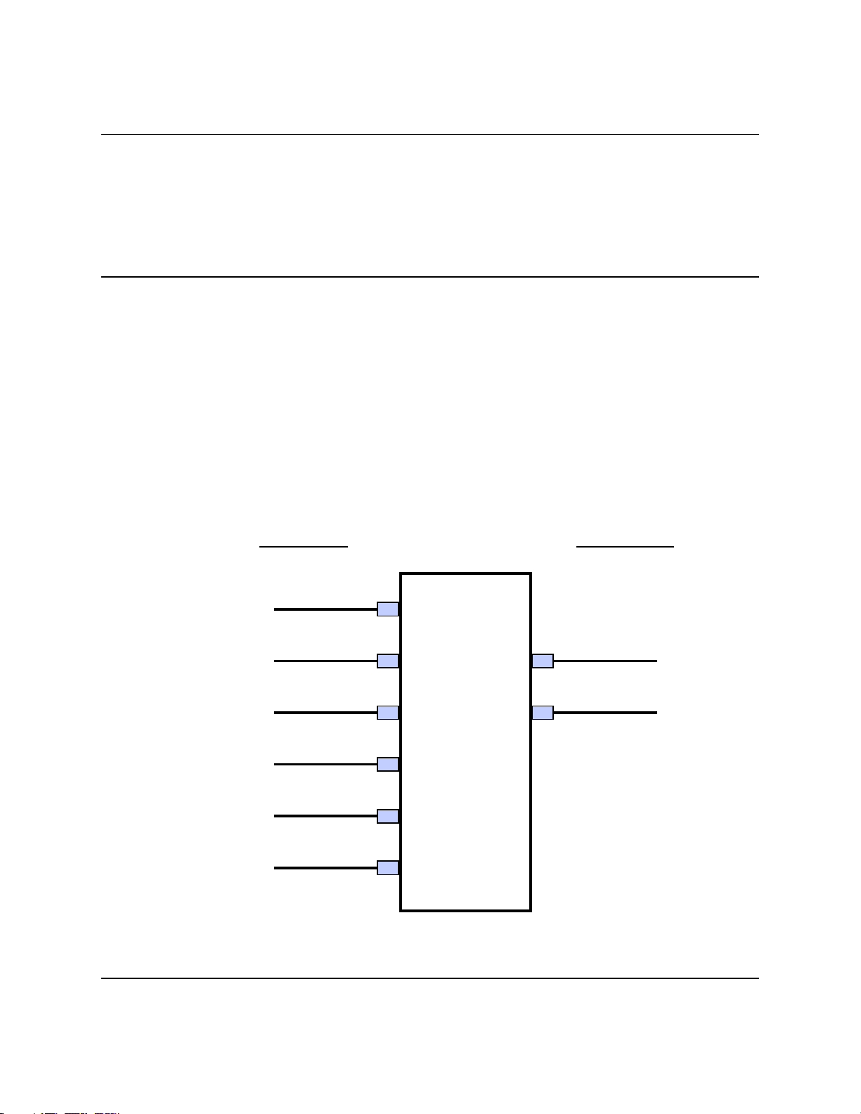
XPA200-7984-I-OPT1, X-Band SSPA Maintenance and Troubleshooting
SECTION 6
Maintenance and Troubleshooting
6.1 General
This section is intended to provide procedures to assist
operator and maintenance personnel in the checkout, maintenance
and troubleshooting of the SSPA. COMTECH recommends that spare
replacement SSPA’s be used to replace SSPA’S removed from the
system for maintenance. Troubleshooting procedures are provided
for fault isolation to the module level.
The input and output signals, the interconnecting cables and
The location of the modules are as shown in Figure 6-1.
REAR PANEL
SSPA RF INPUT
AC POWER INPUT
CUSTOMER DISCRETE
J1
J3
J4
200 Watt
FRONT PANEL
RF INPUT SAMPLE
RF OUTPUT SAMPLE
X-Band
Solid State
SSPA RF OUTPUT
J2
High Power
Amplifier
RS-485/-232C COMM LINK
COMBINER INTERFACE
J6
J5
Figure 6-1. SSPA Signal and Interconnecting Cable Diagram
XPA200-7984-I-OPT1, Rev.2 6-1
Page 74

XPA200-7984-I-OPT1, X-Band SSPA Maintenance and Troubleshooting Maintenance and Troubleshooting
6.2 Maintenance Testing
Use the instructions in Section 2.0 for installing the SSPA
for checkout, and the procedures in Section 3.0, System
Operation, for operating the SSPA.
The SSPA is a X-Band SSPA with an RF output level of +53.0
minimum dBm at 1 dB compression.
6.2.1 Test Point Samples
The RF input and output can be monitored at the RF Sample
Test Points on the front panel. Type N connectors are provided.
The sample RF input level is -20 dBc nominal, and the RF output
level is -40 dBc nominal. Actual measured data for these sample
ports is located on the front panel.
6.3 Troubleshooting
SSPA operating problems can be identified by first observing
the status indicators on the front panel. When a fault condition
is indicated, the specific fault, or faults, can be identified in
the Current Faults Function Menu, Figure 3-4, which is accessed
through the local operation key-pad and displayed on the LCD
display located on the front panel. The status of SSPA functions
is displayed in the Monitor Status Functions Menu, Figure 3-3.
Refer to paragraph 3.3, operation, for a description of the SSPA
command functions; also, check the status of the mute condition
in the configuration menu (i.e.: Mute = “On” means that the
amplifier will be muted.)
6.3.1 SSPA Faults
Check the Monitor Status Functions Menu for possible faults,
or an indication of a marginal performance tolerance condition.
XPA200-7984-I-OPT1, Rev.2 6-2
Page 75

XPA200-7984-I-OPT1, X-Band SSPA Maintenance and Troubleshooting Maintenance and Troubleshooting
6.3.1.1 Prime Power
Check the circuit breaker on the rear panel. The required
prime power is 115 VAC, at typically 2600 VA (approx 1800W).
6.3.1.2 DC Power Supply Modules
! Power Supply, +10 VDC:
A fault ("FT") indicates a voltage level exceeding
+/- 10% of the power supply voltage. Check the
output of the DC Power Supply Module. Check all
connections to make sure they are secure. If the
voltage exceeds +/- 10%, or the fault still
exists, return the SSPA to COMTECH for repair.
! Power Supply, +28 VDC:
A fault ("FT") indicates a voltage level exceeding
+/- 10% of the power supply voltage. Check the
output of the DC Power Supply Module. Check all
connections to make sure they are secure. If the
voltage exceeds +/- 10%, or the fault still
exists, return the SSPA to COMTECH for repair.
! Power Supply, +12 VDC:
A fault ("FT") indicates a voltage level exceeding
+/- 10% of the power supply voltage. Check the
output of the DC Power Supply Module. Check all
connections to make sure they are secure. If the
voltage exceeds +/- 10%,or the fault still exists,
return the SSPA to COMTECH for repair.
! Power Supply, -12 VDC
A fault ("FT") indicates a voltage level exceeding
+/- 10% of the power supply voltage. Check the
output of the DC Power Supply Module. Check all
connections to make sure they are secure. If the
voltage exceeds +/- 10%,or the fault still exists,
return the SSPA to COMTECH for repair.
XPA200-7984-I-OPT1, Rev.2 6-3
Page 76

XPA200-7984-I-OPT1, X-Band SSPA Maintenance and Troubleshooting Maintenance and Troubleshooting
! +5 VDC:
A fault ("FT") indicates a voltage level exceeding
+/- 10% of the power supply voltage. Check the
output of the +12 VDC Power Supply Module, check
for other module faults, and check all
connections. If the fault still exists, remove
the SSPA and return it to COMTECH for repair.
6.3.1.2 DC Power Supply Modules (continued)
! -5 VDC:
A fault ("FT") indicates a voltage level exceeding
+/- 10% of the power supply voltage. Check the
output of the -12 VDC Power Supply Module, check
for other module faults, and check all
connections. If the fault still exists, remove
the SSPA and return it to COMTECH for repair.
6.3.1.3 Temperature Fault
! SSPA OVER TEMPERATURE FAULT:
A fault ("FT") indicates that the SSPA is
over temperature. Make sure adequate ventilation
is supplied to the unit, and that the airflow path
is not obstructed. (See installation
instructions, Sect. 2). Also, make sure the
ambient air is within the 0 - 50 degree C
operating limits. If the unit still shows a fault
after following these procedures, turn the prime
power switch off and return the SSPA to COMTECH
for repair.
6.3.1.4 Monitor and Control Board
! Loss of LCD or LED Displays:
Check the 5V LED indicator on the Monitor and
Control Board. If the 5V LED indicator is not
illuminated, check the SSPA prime power and
DC power supply connections to make sure they are
XPA200-7984-I-OPT1, Rev.2 6-4
Page 77

XPA200-7984-I-OPT1, X-Band SSPA Maintenance and Troubleshooting Maintenance and Troubleshooting
secure. If the fault still exists, remove the
SSPA and return it to COMTECH for repair.
! Loss of Serial Communication Interface:
If there is also a DC power supply fault, first
check the DC power supply. If there are no DC
power supply fault, check the serial communications
(COM 1) Connector J6 and cable to make sure they are
secure. If the fault still exists, remove the SSPA
and return it to COMTECH for repair.
See Section 7 for additional troubleshooting help.
6.4 Returning the SSPA to COMTECH
6.4.1 Return Material Authorization (RMA)
To return an in-warranty or out-of-warranty SSPA to COMTECH
for repair or replacement:
1. Request a Return Material Authorization (RMA) number
from the COMTECH Customer Service Representative,
1-(480)333-4357.
2. Provide the Customer Service Representative with the
following information:
a. Model number.
b. Serial number.
c. Description of the problem.
d. Describe action taken to identify the problem.
e. Name and telephone number of the company contact.
For more information regarding the COMTECH warranty policy,
please refer to the warranty statement located on the back of the
title page.
XPA200-7984-I-OPT1, Rev.2 6-5
Page 78

XPA200-7984-I-OPT1, X-Band SSPA Maintenance and Troubleshooting Maintenance and Troubleshooting
6.4.2 Shipment to COMTECH
The SSPA being shipped should be packed in it's original
shipping container with proper packing material to prevent
possible shipping damage.
Ship the SSPA, prepaid, to COMTECH. Provide the following
address on the shipping label, with the RMA number clearly marked
on the label and the shipping container:
COMTECH EF Data Corp.
2114 W. 7
th
Street
Tempe, Arizona 85281 U.S.A.
Attention: Customer Service Department
RMA Number:
6.5 Product Application, Upgrading or Training Information
To obtain product application, upgrade or training
information, Please contract the Customer Service Representative,
1-(480)333-4357.
XPA200-7984-I-OPT1, Rev.2 6-6
Page 79

XPA200-7984-I-OPT1, X-Band SSPA Addendum
Addendum
7.1 General
This addendum section contains additional items as listed
below:
1. Additional Troubleshooting helps (Table 7.1)
2. Wiring diagram.
3. Top level parts list.
7.2 Additional Troubleshooting Information.
Additional Troubleshooting Help
SYMPTOM
Unit does not turn on
(no display, no front
panel lights, no
fans).
Either one or both
fans do no turn on.
Table 7.1
POSSIBLE CAUSES
Power cord not plugged in.
Faulty wiring to 28V power
supply.
28V power supply fault.
Faulty wiring, bad
SOLUTIONS
Check power cord connections.
With input power cord
removed, check wiring and
connections to 28V power
supply.
Check output of 28Vdc power
supply.
Note: At power-up, the fans
are sequenced on. Therefore,
in normal operation, the
second fan does not turn on
until approximately 3 seconds
after the first fan.
Check AS/0206 to ensure that
XPA200-7984-I-0PT1, Rev.2 7.1
Page 80

XPA200-7984-I-OPT1, X-Band SSPA Addendum
SYMPTOM
Display not turning
on, missing text,
incorrect
backlighting, etc.
POSSIBLE CAUSES
connections.
Firmware not properly seated.
Faulty 28V power supply.
Failed fan, faulty control
circuitry.
Firmware not properly seated.
Faulty wiring, bad
connections.
SOLUTIONS
connections at P4 and P5 are
not loose. Also check the
cable connection at the fans.
There should be approximately
24Vdc between the two pins at
the fan. Check cable for
continuity. Replace cable
wiring if faulty or return to
factory for cable repair.
The fans are microprocessor
controlled and monitored.
Therefore, make sure U11 and
U12 on AS/0200 are properly
seated.
Check the output voltage of
the 28V power supply. (Either
via the front panel “MONITOR”
menu or using a voltmeter.)
Replace Fan if faulty or
return to factory for repair
or replacement.
Ensure U11 and U12 on AS/0200
are properly seated.
Ensure good cable connections
from M&C cards AS/0200 and
AS/0206 to display card
located behind front panel.
Check cables for continuity.
Replace cable wiring if
faulty or return to factory
for repair.
No RF output, or
output level much
less than expected.
Failed display, failed
display control card.
Failed circuitry on AS/0200
or AS/0206.
Mute function activated. Check the “CONFIGURATION”
Return to factory for repair.
Return to factory for repair.
menu to determine if the mute
function has been activated.
“MUTE = ON” means that the
unit is muted. Turn the
“MUTE” feature to “off” to
allow RF amplification of the
input signal.
The “AMPLIFIER = OFF” feature
XPA200-7984-I-0PT1, Rev.2 7.2
Page 81
XPA200-7984-I-OPT1, X-Band SSPA Addendum
SYMPTOM
POSSIBLE CAUSES
“AMPLIFIER = OFF” feature
activated.
Large customer attenuation
values selected.
Input power level not
correct, perhaps due to
faulty input cable.
Faulty input connection from
10V power supplies.
Faulty SSPA control cable or
connection.
SOLUTIONS
allows for lower current draw
from the prime power source
under standby conditions. To
obtain RF output, ensure that
this feature is set to
“AMPLIFIER = ON”.
Check the “ATTENUATION = XX”
setting in the
“CONFIGURATION” menu. Lower
value to get more gain.
Use the input sample port on
the front panel to determine
that the input power level is
as expected.
Use the “MONITOR” menu to
check the internal level of
PS1 and PS2. The levels
should be near 10V. If not
correct, use a voltmeter to
measure the voltage where the
#8 wires enter the amplifier
unit. WITH UNIT OFF, tighten
connections if necessary.
Check the 25 pin ribbon cable
connections at the amplifier
module and at AS/0200.
No remote control
communication.
Failed SSPA amplifier module.
Incorrect cable connections.
Improper communication
This can usually be
determined by using the
“MONITOR” menu to check the
DC current levels being drawn
by each transistor inside the
amplifier module.
Any transistor (QX) current
that is 50 percent more or
less than nominal would
probably indicate a failure.
Nominal values:
Q1=20mA, Q2,Q3=1.5A,Q4=2A,
Q5=4A, Q6-Q11=7.5A, Q12Q19=9A.
There are no user serviceable
parts inside the amplifier
module. Return to factory
for repair.
Make sure cable is wired as
described in Section 5.
Check settings of SSPA along
XPA200-7984-I-0PT1, Rev.2 7.3
Page 82

XPA200-7984-I-OPT1, X-Band SSPA Addendum
SYMPTOM
Amplifier Temperature
fault
POSSIBLE CAUSES
settings between SSPA and
controlling terminal.
Entry mode of unit set to
“LOCAL”.
Operating temperature limits
exceeded.
Air intake or air exhaust
paths obstructed.
Fan failure.
SOLUTIONS
with remote control terminal
software.
Change entry mode setting in
“CONFIGURATION” menu to
“REMOTE”.
Note: The SSPA module
contains an internal
temperature monitor that will
shut off the unit (i.e. turn
off the 10V supplies) if the
heatsink temperature becomes
excessive. This prevents the
transistors from overheating
and destruction. After
cooling down below the trip
point, the unit will
automatically restart.
Do not exceed 50C ambient
input air temperature.
(Recommend 40C maximum)
Remove obstructions to ensure
adequate air flow and proper
amplifier cooling.
Check fan operation as
described earlier in this
table. Replace fan(s) if
necessary.
Defective transistor(s) in
amplifier module.
Use “MONITOR” menu to check
transistor currents. Compare
readings with nominal values
listed earlier. Report
excessive readings to
manufacturer and return
entire unit to manufacturer
for repair. There are no
user serviceable parts inside
the SSPA amplifier module.
XPA200-7984-I-0PT1, Rev.2 7.4
Page 83

XPA200-7984-I-OPT1, X-Band SSPA Addendum
SYMPTOM
10V Power Supply
Fault (PS1 or PS2)
Faulty/Improper
Redundancy Switch
operation
POSSIBLE CAUSES
Faulty wire or connection.
Excessive current draw from
transistor inside amplifier
module.
Faulty Power Supply.
Faulty wiring or connections.
SOLUTIONS
Check cable and connection
from both PS1 and PS2 to
amplifier module. On outside
of module, measure voltage.
Expected voltage = 10 +/.5Vdc.
Use “MONITOR” menus to check
transistor currents. Record
excessive values and return
entire unit to manufacturer
for repair.
Return failed power supply
for repair. Replace with new
power supply.
Improper settings.
XPA200-7984-I-0PT1, Rev.2 7.5
Page 84

7.3 WIRING DIAGRAM (next page).
Page 85
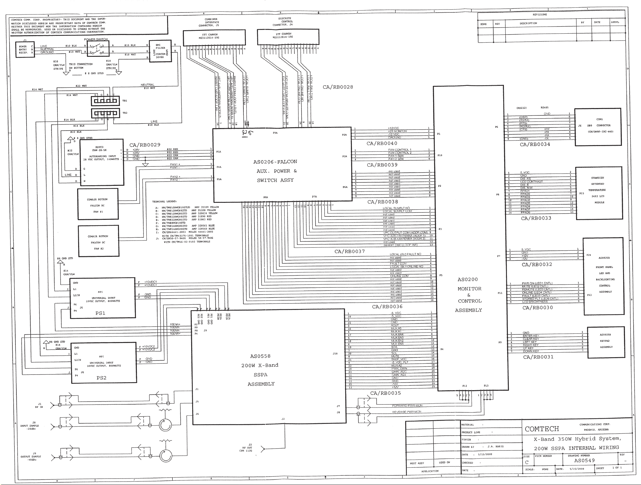
Page 86

Page 87

XPA200-7984-I, X-Band SSPA Addendum
7.4 PARTS LIST (next pages)
XPA200-7984-I-0PT1, Rev.2 7.6
Page 88
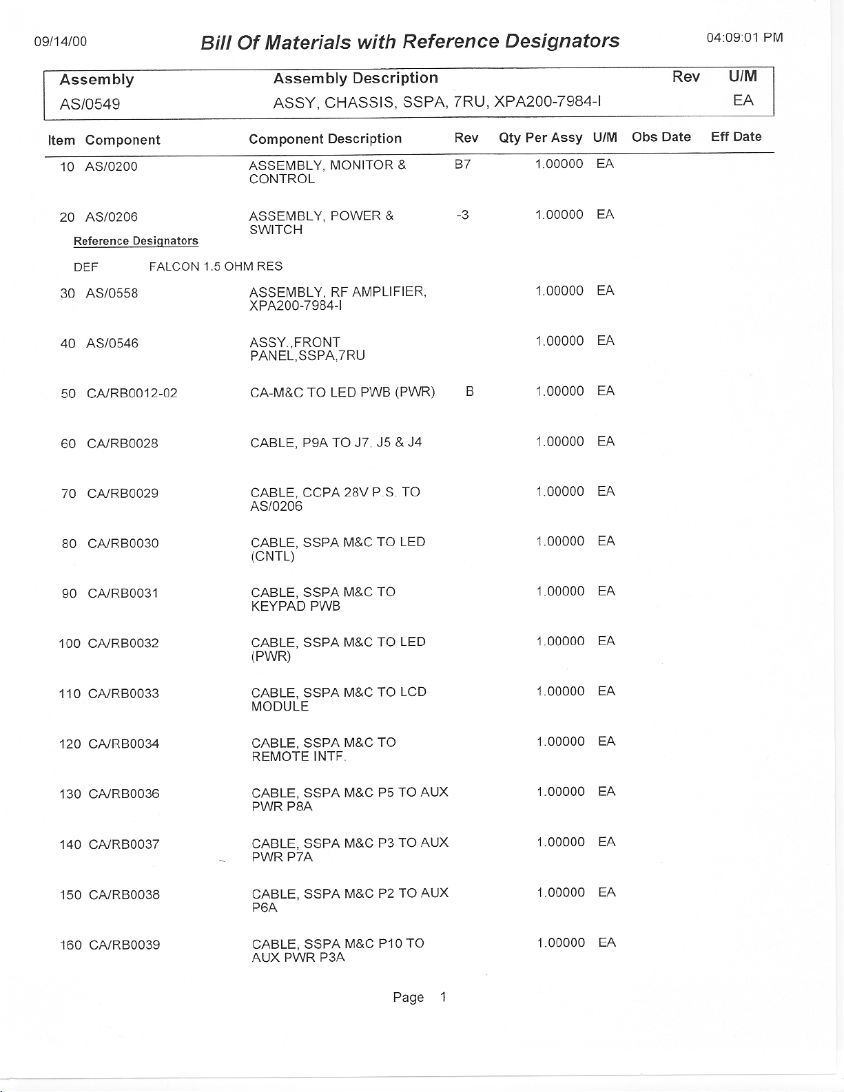
Page 89
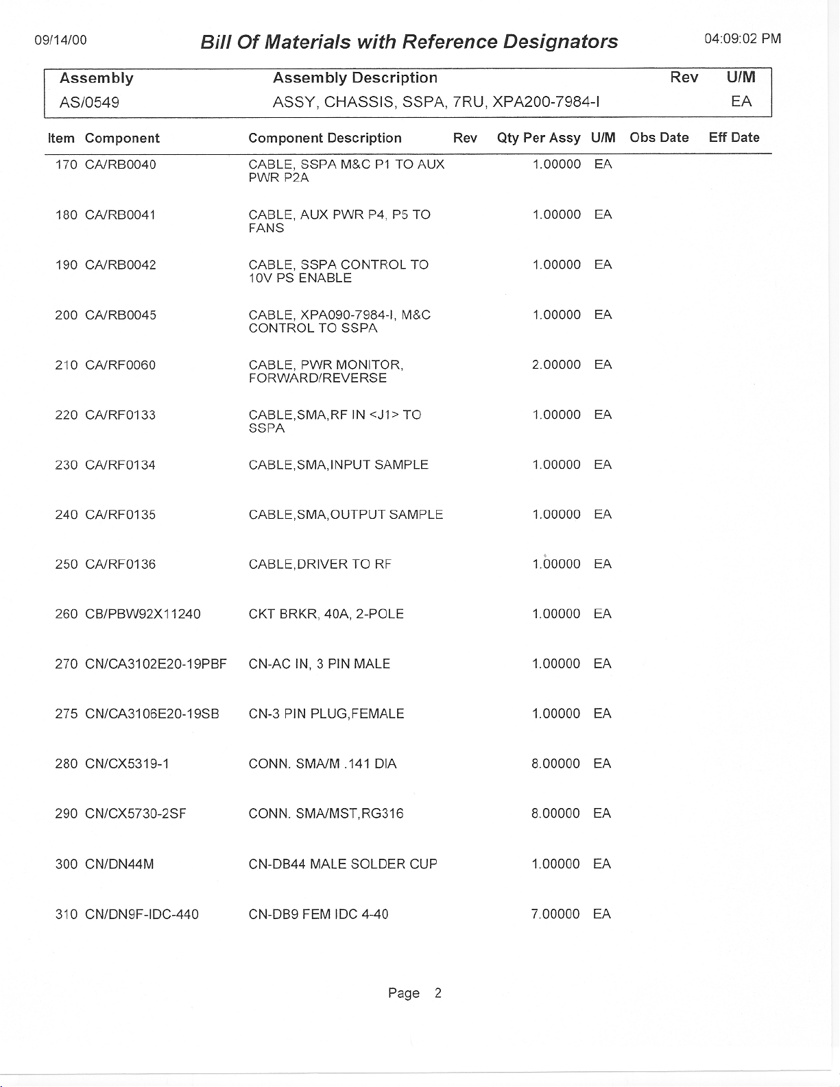
Page 90

Page 91
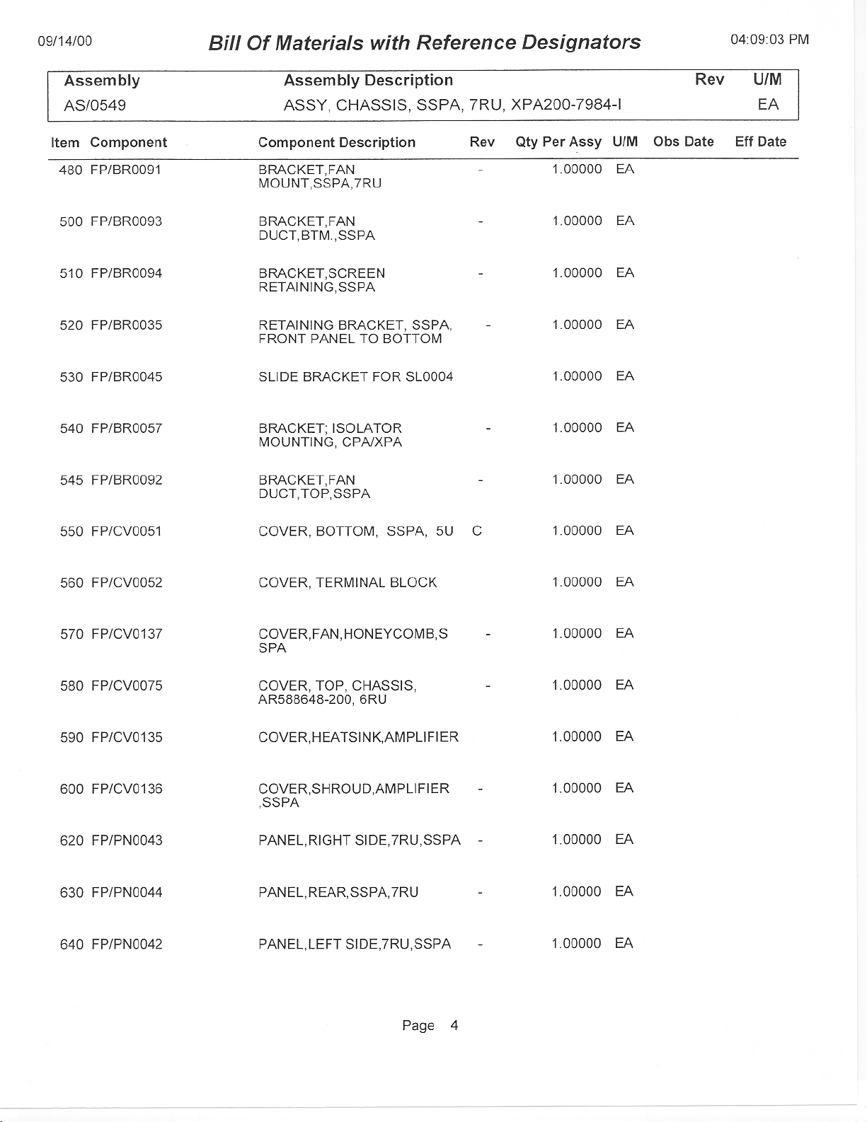
Page 92

Page 93

Page 94

Page 95

METRIC CONVERSIONS
Units of Length
Unit
1 centimeter — 0.3937 0.03281 0.01094
1 inch 2.540 — 0.08333 0.2778
1 foot 30.480 12.0 — 0.3333
1 yard 91.44 36.0 3.0 —
Centimeter
Inch
Foot
Yard
Mile
6.214 x 10
1.578 x 10
1.893 x 10
5.679 x 10
Meter
-6
-5
-4
-4
0.01 — —
0.254 — 25.4
0.3048 — —
0.9144 — —
Kilometer Millimeter
1 meter 100.0 39.37 3.281 1.094
1 mile
1 mm — 0.03937 — — — — — —
1 kilometer — — — — 0.621 — — —
1.609 x 10
5
6.336 x 10⁴ 5.280 x 10³ 1.760 x 10³
6.214 x 10
-4
—
— — —
1.609 x 10³
1.609 —
Temperature Conversions
Unit
32° Fahrenheit
212° Fahrenheit
-459.6° Fahrenheit
° Fahrenheit
—
—
—
° Centigrade
0
(water freezes)
100
(water boils)
273.1
(absolute 0)
Formulas
C = (F - 32) * 0.555
F = (C * 1.8) + 32
Units of Weight
Unit
1 gram — 0.03527 0.03215 0.002205 0.002679 0.001
Gram
Ounce
Avoirdupois
Ounce
Troy
Pound
Avoir.
Pound
Troy
Kilogram
1 oz. avoir. 28.35 — 0.9115 0.0625 0.07595 0.02835
1 oz. troy 31.10 1.097 — 0.06857 0.08333 0.03110
1 lb. avoir. 453.6 16.0 14.58 — 1.215 0.4536
1 lb. Troy 373.2 13.17 12.0 0.8229 — 0.3732
1 kilogram
1.0 x 10
3
35.27 32.15 2.205 2.679 —
Page 96

2114 WEST 7TH STREET TEMPE ARIZONA 85281 USA
480 • 333 • 2200 PHONE
480 • 333 • 2161
FAX
 Loading...