

Page 1

Comtech EF Data is a n
AS9100 Rev B / ISO9001:2000 Registered Company
Vipersat
VMS v3.12.x
VIPERSAT Management System
User Guide
MN/22156 Revision 12
Page 2

Page 3
VMS v3.12.x
VIPERSAT Management System
User Guide
Part Number MN/22156
Document Revision 12
Software version 3.12.0
March 5, 2014
Page 4

COMTECH EF DATA
VIPERSAT Network Products Group
3215 Skyway Court
Fremont, CA 94539
USA
Phone: (510) 252-1462
Fax: (510) 252-1695
www.comtechefdata.com
Part Number: MN/22156
Revision: 12
Software Version: 3.12.0
©2014 by Comtech EF Data, Inc. All rights reserved. No part of this document may be
copied or reproduced by any means without prior written permission of Comtech EF
Data.
IMPORTANT NOTE: The information contained in this document supersedes all
previously published information regarding this product. Product specifications are
subject to change without prior notice.
Comtech reserves the right to revise this publication at any time without obligation to
provide notification of such revision. Comtech periodically revises and improves its
products and therefore the information in this document is subject to change without prior
notice. Comtech makes no warranty of any kind with regard to this material, including but
not limited to the implied warranties of merchantability and fitness for a particular
purpose. No responsibility for any errors or omissions that may pertain to the material
herein is assumed. Comtech makes no commitment to update nor to keep current the
information contained in this document.
Patents and Trademarks
All products, names and services are trademarks or registered trademarks of their
respective companies. See all of Comtech EF Data’s patents and patents pending at
http://patents.comtechefdata.com.
Printed in the United States of America
Page 5

Document Revision History
Revision Date Description
07/03/07Initial Release.
Note: This new document part number, MN/22156, supersedes the previous
VMS User Guide part number, 22156.
New functionality in v3.5.x: VMS N:1 Redundancy; Site Distribution Lists;
CDM-700 Out-of-Band Driver; CDD-564IF InBand Driver.
1 10/15/07 New functionality in v3.6.0: Roaming (SOTM), ROSS; Global Map View.
22/08/08New functionality in v3.6.2: VMS Virtual Network Operator (VNO).
38/30/08New functionality in v3.6.3: SLM-5650A Inband/OOB Driver; OBCM; CDM-
42/24/09New functionality in v3.6.4: Event Log Filtering and VMS Event Conduit
55/26/09New functionality in v3.7.1: Guaranteed Bandwidth; Enhanced Switching;
6 10/30/09 New functionality in v3.7.2: Point-to-Point Switching; Remote Site Wizard;
75/05/10New functionality in v3.7.3: Database Protection and Hardening; SHOD/
83/26/12New functionality in v3.8.1: Support for Advanced VSAT Series800—
96/21/12New functionality in v3.9.1/3.9.2: Support for Out-of-Band (non-Vipersat)
570/570L Out-of-Band Driver; Satellite Advanced Switching for SOTM and
Antenna Mesh Compensation Factor; Basic Guaranteed Bandwidth and CIR.
Service; VMS Redundancy Status and Auto Synchronize; Up/Down Converter
Naming.
Integrated Circuit Scheduler. Not formally released.
Application Image Manager; Application Policies Priority; Event Relay Server;
Satellite Reservations Status; Antenna Visibility; Multi-Band LNB Roaming
Support.
Mesh Data Rate Limits; Independent Forward and Return Path Settings for
Reservations and Advanced Switching ModCods; Site Reservation Control;
Automatic Network Registration.
CDM-800 Gateway Router, CDM-840 Remote Router, CDD-880 MultiReceiver Router—providing Monitor and Control with dSCPC; External
parameter change log event.
modems; Enhanced Application Policies; Enhanced Remote Site Wizard;
Enhanced SNMP Modem Manager: Polling parameters, Declare Modem
parameters, and CDM-625 driver.
10 10/16/12 New functionality in v3.10.1: SNMP module Northbound Interface (NBI) to
external network management systems.
Page 6

Revision Date Description
11 3/15/13 New functionality in v3.11.0: Dual-level User Account Control; ROSS driver
enhancement; SOTM Roaming support for Advanced VSAT Series800;
CDM-750 driver with OOB Switching; Northbound Interface with caching for
CDM-570/L, CDD-56X/L, and SLM-5650/A.
12 3/05/14 New functionality in v3.12.0: Bandwidth Exclusion Zones, Carrier Presence
Switching; Operations Monitor, ViperView Multi-Select, Antenna View Dragand-Drop, Active Demodulator Blocking, Codecast Image Upgrade,
Bandwidth View Animation options, Dual Speed Status Update Timer, Event
Log Auto Scroll control, CDM-760 SNMP driver for OOB switching; RESTful
Interface for NMS.
Page 7

Table of Contents
Chapter 1
General
How to Use This Manual . . . . . . . . . . . 1-1
Manual Organization . . . . . . . . . . . . 1-1
Chapter 1 — General . . . . . . . . . 1-1
Chapter 2 — VMS Installation . . . . . 1-1
Chapter 3 — VMS Configuration . . . 1-2
Chapter 4 — Configuring Network
Modems . . . . . . . . . . . . . . . 1-2
Chapter 5 — Configuring ROSS Units 1-2
Chapter 6 — VMS Services . . . . . . 1-2
Chapter 7 — Out-of-Band Units . . . . 1-2
Appendix A — VMS Cross Banding . . 1-2
Appendix B — Antenna Visibility. . . . 1-2
Appendix C — Redundancy . . . . . . 1-2
Appendix D — SNMP Traps . . . . . 1-2
Appendix E — Automatic Switching . . 1-3
Appendix F — Northbound Interface . 1-3
Appendix G — VMS Client Users . . . 1-3
Appendix H — Glossary . . . . . . . . 1-3
Conventions and References . . . . . . . . 1-3
Product Description . . . . . . . . . . . . . . 1-5
Introduction . . . . . . . . . . . . . . . . . 1-5
VMS Features . . . . . . . . . . . . . . . . 1-7
VMS Operation & Architecture . . . . . . . 1-9
New in this Revision . . . . . . . . . . . 1-11
v 3.11.3 Release . . . . . . . . . . . . 1-11
Carrier Presence Switching . . . . . . 1-11
v3.12.0 Release . . . . . . . . . . . . 1-11
Preemptive Bandwidth Pool Management
1-11
RESTful Interface . . . . . . . . . . . 1-11
CDM-760 Device Driver . . . . . . . . 1-12
Operations Monitor . . . . . . . . . . 1-12
Multi-Select . . . . . . . . . . . . . . 1-12
Drag-and-Drop . . . . . . . . . . . . 1-13
Block Active Demodulator . . . . . . . 1-13
Codecast Image Upgrade . . . . . . . 1-13
Spectrum View Animation . . . . . . . 1-13
Dual Speed Status Update Timer . . . 1-14
Event View Auto Scroll Control . . . . 1-14
Contact Information . . . . . . . . . . . . . . 1-15
Customer Support . . . . . . . . . . . 1-15
Comtech EF Data Headquarters . . . 1-15
Reader Comments / Corrections . . . 1-15
Chapter 2
VMS Installation
General . . . . . . . . . . . . . . . . . . . . . 2-1
VMS Server - MS Windows Update Setting
2-2
Types of Installation . . . . . . . . . . . . 2-3
Redundant Server Upgrade . . . . . . . 2-4
Prepare Server for VMS Installation . . . . . . 2-5
Limit DEP (Data Execution Prevention) . . 2-5
Back Up VMS Database (Upgrade) . . . . 2-7
Prepare for Crypto-Key Updating (Upgrade) 2-9
Stop Previous VMS Version (Upgrade) . . 2-11
Uninstall Previous VMS Version (Upgrade) . .
2-13
Update USB Crypto-Key (Upgrade) . . . 2-15
VMS Server Installation . . . . . . . . . . . 2-16
Management Security Installation — Option . .
2-22
Set Com Security for VMS . . . . . . . . 2-23
Verify Server Installation . . . . . . . . . 2-27
VMS Service Start Failure. . . . . . . 2-29
VMS Client Installation . . . . . . . . . . . . 2-32
Create Client Accounts . . . . . . . . . . 2-33
Verify Client Installation . . . . . . . . . . 2-33
ViperGlobe Installation . . . . . . . . . . . . 2-35
Installation Procedure . . . . . . . . . 2-35
Verify ViperGlobe Installation . . . . . 2-39
VMS Web Services Installation & Configuration . .
2-40
Services Overview . . . . . . . . . . . . 2-40
SOAP Server Prerequisites . . . . . . . . 2-41
Server Preparation . . . . . . . . . . . . 2-42
Uninstall Previous Version (Upgrade) . . . 2-52
Installation Procedure . . . . . . . . . . . 2-54
VMS Installation . . . . . . . . . . . . 2-54
SOAP Services Installation . . . . . . 2-54
Web Applications Installation . . . . . 2-58
Server Configuration . . . . . . . . . . . 2-58
Set Up Log On Account . . . . . . . . 2-58
ToC i
Page 8

MN/22156, rev 12
Chapter 3
VMS Configuration
General . . . . . . . . . . . . . . . . . . . . 3-1
Configuration Alerts . . . . . . . . . . . 3-3
Hardware Configuration . . . . . . . . . . . 3-5
VMS Quick Configuration Guide . . . . . . . 3-7
Start VMS & ViperView . . .[page 3-10]3-7
Configure Vipersat Manager [page 3-12]3-7
Configure RF Manager . . . [page 3-25]3-7
Configure Network Manager [page 3-41]3-8
Set Carrier Flags . . . . . [page 3-46]3-8
Mask Rx Unlock Alarms . . [page 3-50]3-8
Configure InBand Management . . . . .
[page 3-54] . . . . . . . . . . . . . . 3-8
Perform Switching Function Verification .
[page 3-83] . . . . . . . . . . . . . . 3-9
Create Additional Remote Sites with
Remote Site Wizard . . .[page 3-88]3-9
Configure Advanced Switching . . . . .
[page 3-70] . . . . . . . . . . . . . . 3-9
Configure Redundancy . . [page 3-110]3-9
Configure N:M Hub Device Redundancy
3-9
Configure VMS Redundancy . . . . . 3-9
Configure SOTM . . . . . [page 3-110]3-9
Configure Encryption . . . [page 3-116]3-9
Management Security Option . . . . . 3-9
Modem TRANSEC Setting (SLM-5650A
only) . . . . . . . . . . . . . . . . .3-9
VMS Initial Startup Procedure . . . . . . . . 3-10
Configure Server Connection . . . . . 3-10
Vipersat Manager Configuration . . . . . . . 3-12
Activate Server Processes . . . . . . 3-16
Open Event Log . . . . . . . . . . . . 3-16
Configure Event Relay Server . . . . 3-17
Configure Auto Activate . . . . . . . . 3-18
Auto-Discovery Process . . . . . . . 3-19
Backup Database . . . . . . . . . . . 3-22
Client User Authentication . . . . . . 3-23
RF Manager Configuration . . . . . . . . . . 3-25
Create Satellite(s) . . . . . . . . . . . 3-25
Create Transponder(s) . . . . . . . 3-26
Open Spectrum View . . . . . . . . 3-28
Create Bandwidth Pools . . . . . . 3-29
Bandwidth Exclusions . . . . . . . . 3-31
Spectrum View Animation . . . . . . 3-32
Create Site Level RF Chain . . . . . . . . 3-32
Create Antennas . . . . . . . . . . . 3-32
Create Antenna Devices . . . . . . . 3-35
Bind Modulators and Demodulators to
Converters . . . . . . . . . . . . . . . . 3-38
Network Manager Configuration . . . . . . . 3-41
Network Build Procedure . . . . . . . . . 3-41
Create Network(s) . . . . . . . . . . 3-41
Create Groups . . . . . . . . . . . . 3-42
Add Network/Group Satellite(s) . . . . 3-43
Create Sites . . . . . . . . . . . . . 3-44
Add Site Devices . . . . . . . . . . 3-45
Set Carrier Flags . . . . . . . . . . . . . 3-46
Set STDMA Flag . . . . . . . . . . . 3-47
Set Mod and Demod Allocatable Flags 3-49
Mask Rx Unlock Alarms . . . . . . . . . 3-50
Setting the Alarm Masks . . . . . . 3-50
Auto Home State . . . . . . . . . . . . . 3-52
InBand Management Configuration . . . 3-54
Set InBand Management . . . . . . . 3-54
Set InBand Reservations for Guaranteed
Bandwidth . . . . . . . . . . . . . 3-63
Hub Allocatable Modulator & Demodulator
Compatibility . . . . . . . . . . . . 3-68
Considerations for Using Guaranteed
Bandwidth with Advanced Switching3-69
Effect of RF Changes on Reservations . .
3-70
Set InBand Modulation and Coding . 3-70
Advanced Switching Overview . . . 3-70
Roaming with Advanced Switching . 3-71
ModCods Configuration . . . . . . 3-72
Set SHOD Limits . . . . . . . . . . . 3-74
Set InBand Application Policies . . . 3-76
Define InBand Distribution Lists . . . 3-81
Switching Function Verification . . . . . . 3-83
Remote Site Wizard . . . . . . . . . . . 3-88
Network Manager and ViperGlobe . . . .3-101
Redundancy Configuration . . . . . . . .3-110
N:M Device Redundancy . . . . . . .3-110
VMS Redundancy . . . . . . . . . . . 3-110
SOTM Configuration . . . . . . . . . . . 3-110
Encryption Configuration . . . . . . . . . 3-116
Management Security Option . . . . . 3-116
Modem TRANSEC Setting . . . . . . 3-117
ii VMS User Guide
Page 9

MN/22156, rev 12
Chapter 4
Configuring Network Modems
General . . . . . . . . . . . . . . . . . . . . 4-1
Hardware/Software Configuration . . . . . . 4-3
Using Parameter Editor . . . . . . . . . . . . 4-5
Introduction . . . . . . . . . . . . . . . . . 4-5
Tracking Parameter Changes . . . . . . 4-5
Parameter Editor Features . . . . . . . . . 4-6
Information Help . . . . . . . . . . . 4-7
Configuration Changes . . . . . . . . . . . 4-7
Parameter Editor Tree Menu . . . . . . . . . 4-9
General . . . . . . . . . . . . . . . . . . . . 4-11
Unit Name . . . . . . . . . . . . . . . 4-11
System Contact . . . . . . . . . . . . 4-11
System Location . . . . . . . . . . . 4-12
Boot From Slot . . . . . . . . . . . . 4-12
G.703 Clock Extended Mode . . . . . 4-12
Circuit ID . . . . . . . . . . . . . . . 4-12
10 MHz Internal Adjustment . . . . . 4-12
Auto Logout Time . . . . . . . . . . . 4-13
External Reference Frequency . . . . 4-13
Base Frequency . . . . . . . . . . . . 4-13
Rx Constellation Select . . . . . . . . 4-14
Network . . . . . . . . . . . . . . . . . . . . 4-14
Network | Interfaces . . . . . . . . . . . . 4-14
Network | Routes . . . . . . . . . . . . . 4-15
Creating the Static Routes . . . . . . 4-16
Network | ARP . . . . . . . . . . . . . . 4-20
Network | WAN . . . . . . . . . . . . . . 4-22
Network | WAN | Compression . . . . 4-23
Series800 Satellite Framing . . . . . 4-24
Header Compression . . . . . . . . 4-24
Payload Compression . . . . . . . . 4-24
Network | WAN | QoS . . . . . . . . . 4-25
DiffServ QoS Mode . . . . . . . . . 4-26
Assured Forwarding DSCP . . . . . 4-27
Network | WAN | QoS | Groups . . . . 4-28
Group Name . . . . . . . . . . . . . 4-30
Committed Information Rate . . . . 4-30
Maximum Information Rate . . . . . 4-30
Mode . . . . . . . . . . . . . . . . 4-31
ModCod . . . . . . . . . . . . . . . 4-31
Members. . . . . . . . . . . . . . . 4-31
Rules . . . . . . . . . . . . . . . . 4-31
QoS Rule Hierarchy . . . . . . . . . 4-31
Protocol . . . . . . . . . . . . . . . 4-33
Priority . . . . . . . . . . . . . . . . 4-33
WRED . . . . . . . . . . . . . . . 4-34
Enable Filtering . . . . . . . . . . . 4-34
IP Addressing . . . . . . . . . . . . 4-34
Source and Destination Ports . . . 4-34
Minimum & Maximum Bandwidth . . 4-34
Network | WAN | QoS | Rules . . . . 4-35
Network | WAN | RTI . . . . . . . . . 4-37
Network | WAN | ACM . . . . . . . . 4-37
Network | WAN | ECM . . . . . . . . 4-39
Configuring Hub ECM . . . . . . . 4-40
Multicast Address . . . . . . . . . . 4-40
Group ID . . . . . . . . . . . . . . 4-41
Switch Rate . . . . . . . . . . . . . 4-41
Slots In Frame . . . . . . . . . . . 4-41
Guard Band . . . . . . . . . . . . . 4-42
LNB LO . . . . . . . . . . . . . . . 4-42
Frequency Conversion . . . . . . . 4-42
Configuring Remote ECM . . . . . . 4-42
Mode . . . . . . . . . . . . . . . . 4-42
Group ID . . . . . . . . . . . . . . 4-43
Base Power . . . . . . . . . . . . . 4-44
Power Hunt Enable . . . . . . . . . 4-44
Multicast Address . . . . . . . . . . 4-44
LO Frequency . . . . . . . . . . . 4-44
Network | WAN | BERT . . . . . . . . 4-45
State . . . . . . . . . . . . . . . . 4-45
Demod Select . . . . . . . . . . . . 4-46
Pattern . . . . . . . . . . . . . . . 4-46
Test Mode . . . . . . . . . . . . . 4-46
Network | IGMP . . . . . . . . . . . . . . 4-46
Last Member Query Interval . . . . . 4-47
Query Interval . . . . . . . . . . . . . 4-47
Response Interval . . . . . . . . . . 4-48
Network | DHCP . . . . . . . . . . . . . 4-48
Network | NMS . . . . . . . . . . . . . . 4-49
Network ID . . . . . . . . . . . . . . 4-50
Base Port . . . . . . . . . . . . . . . 4-50
Multicast Address . . . . . . . . . . . 4-51
SNMP Trap Destination IP Address . 4-51
Network | Switching . . . . . . . . . . . 4-51
Network | Switching | Load . . . . . . 4-51
Delay . . . . . . . . . . . . . . . . 4-52
Excess Capacity . . . . . . . . . . 4-52
Step Up Threshold . . . . . . . . . 4-53
Step Down Threshold . . . . . . . . 4-53
Network | Switching | ToS . . . . . . 4-53
E1 . . . . . . . . . . . . . . . . . . . . . . 4-56
E1 | Timeslots . . . . . . . . . . . . . . . 4-56
Devices . . . . . . . . . . . . . . . . . . . . 4-58
ToC iii
Page 10

MN/22156, rev 12
Devices | Mod . . . . . . . . . . . . . . . 4-58
FEC Type . . . . . . . . . . . . . . . 4-60
Roll Off . . . . . . . . . . . . . . . . 4-60
ModCod . . . . . . . . . . . . . . . . 4-60
Frequency . . . . . . . . . . . . . . . 4-60
Symbol Rate . . . . . . . . . . . . . 4-60
Data Rate . . . . . . . . . . . . . . . 4-60
Gold Code . . . . . . . . . . . . . . . 4-61
Power Level . . . . . . . . . . . . . . 4-61
Spectrum Invert . . . . . . . . . . . . 4-61
Scrambler . . . . . . . . . . . . . . . 4-61
Carrier State . . . . . . . . . . . . . . 4-62
Terminal Mix . . . . . . . . . . . . . . 4-62
Framing . . . . . . . . . . . . . . . . 4-62
Interface Type . . . . . . . . . . . . . 4-62
Link Adaptation . . . . . . . . . . . . 4-62
Devices | Demod . . . . . . . . . . . . . 4-64
Automatic Active / Alternate Switch . . 4-65
Rx Terminal Mix . . . . . . . . . . . . 4-66
Gold Code . . . . . . . . . . . . . . . 4-66
Es/N0 Alarm Point . . . . . . . . . . 4-66
Spectrum Invert . . . . . . . . . . . . 4-67
Scrambler . . . . . . . . . . . . . . . 4-67
Rx Terminal Mix . . . . . . . . . . . . 4-68
Acquisition Range . . . . . . . . . . . 4-68
Eb/N0 Alarm Point . . . . . . . . . . 4-68
Devices | LNB . . . . . . . . . . . . . . . 4-68
Devices | BUC . . . . . . . . . . . . . . 4-69
Chapter 5
Configuring ROSS Units
General . . . . . . . . . . . . . . . . . . . . 5-1
Status and Control . . . . . . . . . . . . . . 5-2
ROSS Status View . . . . . . . . . . . . . 5-2
ROSS Control Menu . . . . . . . . . . . . 5-4
Open . . . . . . . . . . . . . . . . . . 5-4
Soft Reset . . . . . . . . . . . . . . . . 5-5
Hard Reset . . . . . . . . . . . . . . . 5-5
Configure . . . . . . . . . . . . . . . . 5-5
Upgrade . . . . . . . . . . . . . . . . .5-5
Save to Flash . . . . . . . . . . . . . . 5-5
Force Registration . . . . . . . . . . . 5-5
View Service Areas . . . . . . . . . . . 5-5
Manual Handoff from Service Area . . 5-6
Get Event Log . . . . . . . . . . . . . . 5-7
Delete . . . . . . . . . . . . . . . . . . 5-8
Properties . . . . . . . . . . . . . . . . 5-8
Hardware/Software Configuration. . . . . . 5-9
Using Parameter Editor . . . . . . . . . . . 5-10
Introduction . . . . . . . . . . . . . . . . 5-10
Parameter Editor Features . . . . . . . . 5-10
Configuration Changes . . . . . . . . . . 5-11
Network Settings . . . . . . . . . . . . . 5-12
Modem Settings . . . . . . . . . . . . . 5-12
Management Settings . . . . . . . . . . 5-13
Antenna Control Unit Settings . . . . . . 5-14
Tracking Settings . . . . . . . . . . . . . 5-15
Time and Date Settings . . . . . . . . . 5-16
Chapter 6
VMS Services
General . . . . . . . . . . . . . . . . . . . . . 6-1
ViperView—Monitor and Control . . . . . . . . 6-2
Multiple Views. . . . . . . . . . . . . . . . 6-2
Operations Monitor . . . . . . . . . . . 6-7
Error Detection . . . . . . . . . . . . . . . 6-8
Event Log . . . . . . . . . . . . . . . 6-10
Clear . . . . . . . . . . . . . . . . . 6-12
Reset Filters . . . . . . . . . . . . . 6-12
Twelve Hour . . . . . . . . . . . . . 6-12
Auto Scroll . . . . . . . . . . . . . . 6-12
Filters... . . . . . . . . . . . . . . . . 6-12
Dates Tab . . . . . . . . . . . . . . 6-13
Sources Tab. . . . . . . . . . . . . 6-13
Types Tab . . . . . . . . . . . . . . 6-14
Direct Event Filtering . . . . . . . . 6-16
Export . . . . . . . . . . . . . . . . . 6-16
Refresh . . . . . . . . . . . . . . . . 6-16
Event Relay Server . . . . . . . . . . 6-17
Alarm Masks . . . . . . . . . . . . . . . 6-17
Viewing/Setting Alarm Masks . . . . . 6-18
Unlock Alarm Masks . . . . . . . . 6-19
Diagnostic Switching . . . . . . . . . . . 6-20
Diagnostic Setup . . . . . . . . . . . 6-20
Diagnostic Revert . . . . . . . . . . . 6-22
Diagnostic Reset . . . . . . . . . . . 6-22
Database Backup and Restore . . . . . . 6-23
Backup Procedure. . . . . . . . . . . 6-23
Restore Procedure . . . . . . . . . . 6-25
VMS Service Managers . . . . . . . . . . . 6-27
Network Manager . . . . . . . . . . . . 6-27
Site View . . . . . . . . . . . . . . . 6-28
InBand Management . . . . . . . . . 6-29
Application Policies . . . . . . . . . 6-29
iv VMS User Guide
Page 11

MN/22156, rev 12
Distribution Lists . . . . . . . . . . 6-30
Guaranteed Bandwidth . . . . . . . 6-31
Operator Switch Request . . . . . . . 6-34
Advanced Switching — ModCods . . 6-35
Roaming with Advanced Switching . 6-38
Subnet Manager . . . . . . . . . . . . . 6-38
Declare Subnet . . . . . . . . . . . . 6-39
Populate Subnets . . . . . . . . . . . 6-40
RF Manager . . . . . . . . . . . . . . . . 6-40
Spectrum View Animation . . . . . . . 6-41
Space Segment Exclusions . . . . . . 6-41
Switching Manager . . . . . . . . . . . . 6-43
SNMP Modem Manager . . . . . . . . . 6-44
Redundancy Manager . . . . . . . . . . 6-44
Vipersat Manager . . . . . . . . . . . . . 6-45
Application Image Manager . . . . . . 6-46
Chapter 7
Out-of-Band Units
General . . . . . . . . . . . . . . . . . . . . 7-1
Overview. . . . . . . . . . . . . . . . . . . 7-1
Ethernet IP Interface. . . . . . . . . . . . . 7-2
SNMP Modem Manager. . . . . . . . . . . . 7-4
Set SNMP Timing Intervals . . . . . . . 7-4
Configure SNMP Modem . . . . . . . . 7-5
Parameter View . . . . . . . . . . . . . . . 7-8
Configuring the RF Chain . . . . . . . . . . 7-9
Switching Out-of-Band Modems. . . . . . . . 7-12
Overview. . . . . . . . . . . . . . . . . . 7-12
Out-of-Band Circuit Manager (OBCM) . . 7-13
General . . . . . . . . . . . . . . . . 7-13
Managed and Unmanaged Devices . 7-13
Configuring OOB Circuits . . . . . . . 7-14
OBCM User Interface . . . . . . . . 7-14
Full Duplex Circuit Configuration . . 7-15
Half Duplex Circuit Configuration . . 7-20
Custom Circuit Configuration . . . . 7-26
OOB Circuit Operations . . . . . . . . 7-32
ViperView Circuit Operations . . . . 7-32
Setup and Status Views . . . . . . . 7-33
ArrangeLink Circuit Operations . . . 7-36
VNO Circuit Operations . . . . . . . 7-38
Appendices
Appendix A
VMS Cross Banding
Vipersat Cross Banding Solution . . . . . . A-3
Appendix B
Antenna Visibility
General . . . . . . . . . . . . . . . . . . . . B-1
Using Antenna Visibility . . . . . . . . . . . . B-2
Example — Blocking Spectrum Affected by
Local Ground Frequency Interference B-5
Appendix C
Redundancy
General . . . . . . . . . . . . . . . . . . . . C-1
VMS Redundancy. . . . . . . . . . . . . . . C-2
Description . . . . . . . . . . . . . . . . . C-2
Redundant Hot-Standby. . . . . . . . . . . C-3
Protection Switch-over . . . . . . . . . C-3
Active to Standby Switch . . . . . . . C-3
Active Server Role . . . . . . . . . . . C-4
Standby Server Role . . . . . . . . . . C-4
Automatic VMS Activation . . . . . . . C-4
Server Synchronization . . . . . . . . . . . C-5
Automatic Synchronization . . . . . . . C-5
Manual Synchronization. . . . . . . . . C-5
Server Contention . . . . . . . . . . . . . C-5
Server Status . . . . . . . . . . . . . . . . C-6
Installing & Configuring VMS Server
Redundancy . . . . . . . . . . . . . . . . C-7
Enabled . . . . . . . . . . . . . . . . C-9
Auto Activate . . . . . . . . . . . . . C-9
Auto Synchronize . . . . . . . . . . . C-9
Priority . . . . . . . . . . . . . . . . C-10
Heartbeat Timing . . . . . . . . . . C-10
Redundant Servers . . . . . . . . . C-10
Manual Switching . . . . . . . . . . . . . C-13
Clearing Server Contention . . . . . . . . C-13
N:M Hub Modem Redundancy . . . . . . . . C-14
Description . . . . . . . . . . . . . . . . C-14
Installing N:M Redundancy . . . . . . . . C-16
Hub N:M Redundancy Requirements . C-16
Sample Installation . . . . . . . . . . C-18
Setting Up N:M Redundancy . . . . . . . C-20
ToC v
Page 12

MN/22156, rev 12
Redundancy Manager . . . . . . . . C-21
Create Container . . . . . . . . . . . C-21
Adding Strips and Groups . . . . . . . C-21
Power Strips . . . . . . . . . . . . . C-22
Redundancy Groups. . . . . . . . . C-24
Enabling Heartbeats . . . . . . . . . . C-24
Hub SLM-5650A Modem . . . . . . C-26
Roles. . . . . . . . . . . . . . . . . . C-26
Backup Configurations . . . . . . . . . . C-27
System Restoration . . . . . . . . . . C-28
Pre-Configuring Backup Files . . . . . C-28
Creating Backup Configuration Files C-28
Storing Spare Configurations in Primary
Units . . . . . . . . . . . . . . . . C-30
Preparing Repaired/Replacement Unit C-31
Restoring Acting Primary Unit Spare
Configuration . . . . . . . . . . . . C-32
Cleaning up . . . . . . . . . . . . . . C-32
How N:M Redundancy Works . . . . . . . C-33
Device Failure Detection. . . . . . . . C-33
The Switch-Over Process . . . . . . . C-33
Vipersat Manager . . . . . . . . . . C-33
Redundancy Manager . . . . . . . C-34
Putting Failed Unit Back into Service . . . C-34
Setting Unit to Parked Configuration Mode
C-35
Appendix D
SNMP Traps
Introduction . . . . . . . . . . . . . . . . . . D-1
Using SNMP Traps . . . . . . . . . . . . .D-2
SNMP Traps Available in VMS . . . . . . .D-2
Configuring SNMP Traps . . . . . . . . . . . D-3
Insert. . . . . . . . . . . . . . . . . . . . .D-4
Modify . . . . . . . . . . . . . . . . . . . .D-5
Remove . . . . . . . . . . . . . . . . . . .D-5
Summary . . . . . . . . . . . . . . . . . . . D-6
Appendix E
Automatic Switching
General . . . . . . . . . . . . . . . . . . . . E-1
Hitless Switching . . . . . . . . . . . . . .E-2
Load Switching . . . . . . . . . . . . . . . . E-4
Overview. . . . . . . . . . . . . . . . . . .E-4
Bandwidth Allocation and Load Switching by
the Hub STDMA Burst Controller . . . E-5
Load Switching—STDMA Hub . . . . . . . E-8
Hub Switching Parameters . . . . . . . E-8
Hub Switching Process . . . . . . . . . E-9
Load Switching—Remote . . . . . . . . . E-10
Remote Switching Parameters . . . . E-10
Determination for Switching . . . . . . E-12
Load Switch Example . . . . . . . . . . . E-13
Reduced Data Flow in Switched Mode
(SCPC) . . . . . . . . . . . . . . . E-14
Application Switching . . . . . . . . . . . . . E-16
ToS Switching. . . . . . . . . . . . . . . . . E-18
ToS Background . . . . . . . . . . . . . E-18
Detection of ToS Stamped Packets . . E-19
Configuration . . . . . . . . . . . . . E-20
Example Implementations. . . . . . . . . E-21
ToS Switching Per Device . . . . . . . E-21
ToS Switching Per Traffic Type . . . . E-21
ToS Remarking . . . . . . . . . . . . E-22
ToS to DSCP Value Conversions . . . E-23
Mesh Setup Based on ToS Detection . E-24
Entry Channel Mode Switching . . . . . . . E-25
STDMA Entry Channel Mode . . . . . . E-25
Fail-Safe Operation . . . . . . . . . . E-26
Using STDMA ECM . . . . . . . . . . E-28
Switching an ECM Remote from SCPC to
STDMA . . . . . . . . . . . . . . E-29
Dynamic Entry Channel Mode . . . . . . E-31
Hub Configuration . . . . . . . . . . . E-32
Remote Configuration . . . . . . . . . E-33
ECM Processing . . . . . . . . . . . E-34
Carrier Presence Switching . . . . . . . . . E-36
Overview . . . . . . . . . . . . . . . . . E-36
Switching Parameters / Configuration . . E-36
Entry Rate — InBand Application Policies .
E-36
Ideal Rate & Minimum Rate — InBand
Reservations . . . . . . . . . . . . E-38
Switch All on Roam Away — Satellite Pools
E-41
Switch All Active — Satellite CommandE-42
Appendix F
Northbound Interface
General . . . . . . . . . . . . . . . . . . . . . F-1
vi VMS User Guide
Page 13

MN/22156, rev 12
NBI Feature Description. . . . . . . . . . . . F-2
Operational Status Queries . . . . . . . . . . F-4
Entity Identifiers . . . . . . . . . . . . . . . F-4
Hub Demodulator Eb/No . . . . . . . . . .F-5
Tables Support. . . . . . . . . . . . . . . .F-5
Proxy Caching Support . . . . . . . . . . . . F-6
Operational Procedures . . . . . . . . . . . . F-7
Setup Procedure. . . . . . . . . . . . . . .F-7
Table of Remotes . . . . . . . . . . . .F-8
Alarm Status per Remote . . . . . . . . F-9
Link Statistics . . . . . . . . . . . . . F-10
Hub Demodulator Eb/No . . . . . . F-10
Offset (Frequency). . . . . . . . . . . F-12
Steps to Identify Device . . . . . . . F-13
Caching Test Verification . . . . . . . . . F-14
Cached MIB Variables . . . . . . . . . . . . F-15
Cached 800 Series MIB Values . . . . . . F-15
CDM-800, Version 1.4.x . . . . . . . . F-16
CDM-840, Version 1.4.x . . . . . . . . F-17
CDD-880, Version 1.4.x . . . . . . . . F-17
Appendix G
VMS Client Users
General . . . . . . . . . . . . . . . . . . . . G-1
Server Configuration . . . . . . . . . . . . . G-2
Client Configuration . . . . . . . . . . . . . G-14
Appendix H
Glossary
. . . . . . . . . . . . . . . . . . . . . . . . .H-1
Index
. . . . . . . . . . . . . . . . . . . . . . Index-1
ToC vii
Page 14

{ This Page is Intentionally Blank }
MN/22156, rev 12
viii VMS User Guide
Page 15

List of Figures
Chapter 1 Figures
Figure 1-1 VMS ViperView display. . . . . . . . . . 1-6
Figure 1-2 ViperView Client / Server (VOS)
Relationship . . . . . . . . . . . . . . . . . . . . . . 1-9
Chapter 2 Figures
Figure 2-1 Windows Update window . . . . . . . . 2-2
Figure 2-2 Windows Update, Change Settings
window. . . . . . . . . . . . . . . . . . . . . . . . . . 2-3
Figure 2-3 System Control Panel . . . . . . . . . . . 2-6
Figure 2-4 System Properties—Advanced tab . 2-6
Figure 2-5 DEP tab. . . . . . . . . . . . . . . . . . . . . . 2-7
Figure 2-6 Backup Command, VMS Server . . . 2-8
Figure 2-7 VMS Backup Save As dialog . . . . . 2-9
Figure 2-8 Server Menu, ViperView . . . . . . . . 2-10
Figure 2-9 Serial Number, Server Properties dialog
2-10
Figure 2-10 Licensing Information, Crypto-Key2-11
Figure 2-11 Windows Task Manager, Processes
tab . . . . . . . . . . . . . . . . . . . . . . . . . . . . 2-12
Figure 2-12 Task Manager Warning dialog . . 2-13
Figure 2-13 Programs and Features Control Panel
2-14
Figure 2-14 VMS, Uninstall Program . . . . . . . 2-15
Figure 2-15 Setup Wizard Welcome screen. . 2-16
Figure 2-16 License Agreement screen . . . . . 2-17
Figure 2-17 Installation Type screen . . . . . . . 2-18
Figure 2-18 Service Configuration dialog . . . . 2-18
Figure 2-19 Choose Components dialog . . . . 2-19
Figure 2-20 Choose Install Location dialog . . 2-20
Figure 2-21 Choose Start Menu Folder dialog2-21
Figure 2-22 Installation Complete screen. . . . 2-21
Figure 2-23 VMS Setup Wizard Finish dialog. 2-22
Figure 2-24 Control Panel . . . . . . . . . . . . . . . 2-23
Figure 2-25 Administrative Tools . . . . . . . . . . 2-24
Figure 2-26 Component Services, My Computer
Menu . . . . . . . . . . . . . . . . . . . . . . . . . . 2-24
Figure 2-27 Com Security, Edit Limits . . . . . . 2-25
Figure 2-28 Launch Permissions . . . . . . . . . . 2-25
Figure 2-29 Select Users . . . . . . . . . . . . . . . . 2-26
Figure 2-30 Launch Permissions with New User .
2-26
Figure 2-31 Services, Administrative Tools menu
2-27
Figure 2-32 Vipersat Management System Service
2-28
Figure 2-33 Server Connect dialog. . . . . . . . . 2-28
Figure 2-34 Successful Installation, ViperView2-29
Figure 2-35 Application Error, Event Viewer. .2-30
Figure 2-36 Event Properties window. . . . . . . 2-30
Figure 2-37 Client Installation Type . . . . . . . . 2-33
Figure 2-38 Connect dialog . . . . . . . . . . . . . .2-34
Figure 2-39 ViperView window, VMS Client . . 2-34
Figure 2-40 Vipersat Network Globe Setup Wizard
2-35
Figure 2-41 Choose Start Menu Folder . . . . . 2-36
Figure 2-42 Choose Components. . . . . . . . . .2-36
Figure 2-43 Installing Progress, Network Globe
Setup . . . . . . . . . . . . . . . . . . . . . . . . . .2-37
Figure 2-44 DirectX Download and Installation2-38
Figure 2-45 Completing Vipersat Network Globe
Setup . . . . . . . . . . . . . . . . . . . . . . . . . .2-38
Figure 2-46 ViperGlobe window . . . . . . . . . . .2-39
Figure 2-47 VMS Web Services Components 2-40
Figure 2-48 Administrative Tools Control Panel . .
2-42
Figure 2-49 Server Manager, Add Roles . . . . 2-43
Figure 2-50 Add Roles Wizard . . . . . . . . . . . .2-43
Figure 2-51 Select Server Roles. . . . . . . . . . .2-44
Figure 2-52 Web Server (IIS) Page . . . . . . . .2-45
Figure 2-53 Select Role Services, ASP.NET . 2-46
Figure 2-54 Add Role Services Required . . . . 2-46
Figure 2-55 Select Role Services, IIS 6
Management Compatibility. . . . . . . . . . 2-47
Figure 2-56 Confirm Installation Selections . . 2-48
Figure 2-57 Installation Results . . . . . . . . . . .2-49
Figure 2-58 Server Manager, Roles Summary2-50
Figure 2-59 Component Services. . . . . . . . . .2-50
Figure 2-60 ASP.NET State Service Properties . .
2-51
Figure 2-61 Uninstall VMS SOAP Server Program
2-52
Figure 2-62 Confirm Uninstall Prompt . . . . . .2-53
Figure 2-63 Uninstall Completed . . . . . . . . . .2-53
Figure 2-64 VMS SOAP Server Setup Wizard2-55
Figure 2-65 Choose Start Menu Folder . . . . . 2-55
Figure 2-66 VMS SOAP Server Configuration2-56
LoF ix
Page 16

MN/22156, rev 12
Figure 2-67 SOAP Server Installation Complete .
2-57
Figure 2-68 Services Control Manager, VMS Web
Services . . . . . . . . . . . . . . . . . . . . . . . . 2-57
Figure 2-69 Account Set Up, VMS Web Services
2-58
Chapter 3 Figures
Figure 3-1 Network Configuration example . . . 3-3
Figure 3-2 Alert, Parameter Conflict . . . . . . . . . 3-4
Figure 3-3 CDM-570/570L Telnet Vipersat
Configuration . . . . . . . . . . . . . . . . . . . . . 3-5
Figure 3-4 Connect to Server dialog. . . . . . . . 3-10
Figure 3-5 Initial ViperView Window. . . . . . . . 3-11
Figure 3-6 Vipersat Manager Properties menu
command . . . . . . . . . . . . . . . . . . . . . . . 3-12
Figure 3-7 Vipersat Manager, General dialog 3-13
Figure 3-8 Vipersat Manager, Timeouts dialog3-14
Figure 3-9 Server Processes, Manual Activation .
3-16
Figure 3-10 Activated Server Notification. . . . 3-16
Figure 3-11 Event Log, Open . . . . . . . . . . . . . 3-17
Figure 3-12 Event View Window . . . . . . . . . . 3-17
Figure 3-13 Event Log Properties dialog . . . . 3-18
Figure 3-14 Server Properties, Auto Activate. 3-19
Figure 3-15 Registration of Network Units . . . 3-20
Figure 3-16 Event Log, Node Inserted into Network
3-21
Figure 3-17 Backup VMS Database command3-22
Figure 3-18 VMS Server Properties menu
command . . . . . . . . . . . . . . . . . . . . . . . 3-23
Figure 3-19 Server Properties, VMS Security
Settings . . . . . . . . . . . . . . . . . . . . . . . . 3-24
Figure 3-20 Create Satellite menu command. 3-25
Figure 3-21 Create Satellite dialog. . . . . . . . . 3-26
Figure 3-22 Create Transponder menu command
3-27
Figure 3-23 Create Transponder dialog . . . . . 3-27
Figure 3-24 Satellite Transponder Spectrum View
3-28
Figure 3-25 Create Pool dialog. . . . . . . . . . . . 3-29
Figure 3-26 Satellite Pools dialog. . . . . . . . . . 3-30
Figure 3-27 Bandwidth Pools, Spectrum View3-31
Figure 3-28 Space Segment Exclusions dialog . .
3-31
Figure 3-29 Exclusion Zone, Spectrum View . 3-32
Figure 3-30 Create Antenna dialog . . . . . . . . 3-33
Figure 3-31 Antenna Visibility, Default Settings . .
3-34
Figure 3-32 Create Up Converter menu command
3-35
Figure 3-33 Create Up Converter dialog. . . . .3-36
Figure 3-34 Create Down Converter dialog . . 3-37
Figure 3-35 Converter Icons in Antenna View 3-37
Figure 3-36 Binding Modulator to Up Converter . .
3-38
Figure 3-37 Binding Demodulator to Down
Converter . . . . . . . . . . . . . . . . . . . . . . .3-39
Figure 3-38 STDMA and TDM Carrier Appearance
3-39
Figure 3-39 TDM Carrier Appearance Change3-40
Figure 3-40 Create Network menu command.3-42
Figure 3-41 Create Network dialog. . . . . . . . . 3-42
Figure 3-42 Create Group menu command . . 3-43
Figure 3-43 Create Group dialog . . . . . . . . . . 3-43
Figure 3-44 Drag Satellite to Network. . . . . . .3-44
Figure 3-45 Create Site menu command . . . .3-44
Figure 3-46 Create Site dialog . . . . . . . . . . . . 3-45
Figure 3-47 Drag Antenna onto Site. . . . . . . .3-45
Figure 3-48 Drag Subnet onto Site. . . . . . . . . 3-46
Figure 3-49 Hub BC Demodulator Properties menu
command . . . . . . . . . . . . . . . . . . . . . . .3-47
Figure 3-50 Carrier Flag Setting, Burst
Controller—CDM-570/570L . . . . . . . . . 3-48
Figure 3-51 Carrier Flag Setting, Burst
Controller—SLM-5650A. . . . . . . . . . . .3-48
Figure 3-52 Allocatable Flag, Expansion Demod .
3-49
Figure 3-53 Antenna View Refresh. . . . . . . . .3-50
Figure 3-54 Mask Unlock Alarm, CDM-570/570L,
CDD-56X . . . . . . . . . . . . . . . . . . . . . . . 3-51
Figure 3-55 Mask Unlock Alarm, SLM-5650A 3-51
Figure 3-56 Auto Home State Timeout, CDM-570/
570L . . . . . . . . . . . . . . . . . . . . . . . . . . . 3-53
Figure 3-57 Auto Home State Timeout, SLM-5650A
3-53
Figure 3-58 InBand General Settings dialog. . 3-55
Figure 3-59 InBand Switching Enabled . . . . .3-56
Figure 3-60 InBand Return Path Settings dialog .
3-56
Figure 3-61 Select Remote Modulator . . . . . . 3-57
Figure 3-62 Select Uplink Demodulator . . . . . 3-57
Figure 3-63 Confirmation, Home State Changes .
3-58
Figure 3-64 InBand Return Path Home State,
Populated. . . . . . . . . . . . . . . . . . . . . . .3-58
x VMS User Guide
Page 17

MN/22156, rev 12
Figure 3-65 Select Downlink Modulator . . . . . 3-59
Figure 3-66 InBand Return Path Settings dialog,
Populated. . . . . . . . . . . . . . . . . . . . . . . 3-60
Figure 3-67 InBand Forward Path Settings dialog
3-60
Figure 3-68 Select Remote Demodulator. . . . 3-61
Figure 3-69 Select Downlink Modulator . . . . . 3-62
Figure 3-70 InBand Forward Path Settings dialog,
Populated. . . . . . . . . . . . . . . . . . . . . . . 3-62
Figure 3-71 InBand Return Path Bandwidth
Reservations dialog . . . . . . . . . . . . . . . 3-64
Figure 3-72 Edit Reservation dialog . . . . . . . . 3-65
Figure 3-73 Edit, Additional Transmission
Parameters . . . . . . . . . . . . . . . . . . . . . 3-65
Figure 3-74 Bandwidth Reservation Applied . 3-66
Figure 3-75 Satellite Reservations menu command
3-67
Figure 3-76 Satellite Reservations window . . 3-67
Figure 3-77 Advanced Switching dialog . . . . . 3-72
Figure 3-78 FEC & Modulation Parameters . . 3-73
Figure 3-79 Revisions to AS Table Entries. . . 3-74
Figure 3-80 InBand SHOD Limitations dialog. 3-75
Figure 3-81 InBand Application Policies dialog,
Network . . . . . . . . . . . . . . . . . . . . . . . . 3-76
Figure 3-82 Application Policy Settings . . . . . 3-77
Figure 3-83 Application Policies Table, Network .
3-78
Figure 3-84 Application Policies dialog, Remote
Site. . . . . . . . . . . . . . . . . . . . . . . . . . . . 3-80
Figure 3-85 InBand Distribution Lists, Remote Site
3-82
Figure 3-86 Distribution List dialog. . . . . . . . . 3-82
Figure 3-87 Application Sessions menu command
3-83
Figure 3-88 InBand Sessions dialog. . . . . . . . 3-84
Figure 3-89 Switch Failed message . . . . . . . . 3-84
Figure 3-90 Manual Switch Execution . . . . . . 3-85
Figure 3-91 Remote Status in Group View. . . 3-85
Figure 3-92 Switched Carrier, Spectrum View 3-86
Figure 3-93 Switch Event, Event Log . . . . . . . 3-86
Figure 3-94 Switched Carrier, Hub Antenna View
3-87
Figure 3-95 Create Remote... menu command3-89
Figure 3-96 Remote Site Required Information,
Create Remote... . . . . . . . . . . . . . . . . . 3-89
Figure 3-97 Select Satellite, Remote Site. . . . 3-90
Figure 3-98 Select Remote Subnet . . . . . . . . 3-90
Figure 3-99 Select Reference Site . . . . . . . . . 3-91
Figure 3-100 Select Return Path Modulator, InBand
Switching . . . . . . . . . . . . . . . . . . . . . . .3-92
Figure 3-101 Select Forward Path Demodulator,
P2P Switching . . . . . . . . . . . . . . . . . . .3-93
Figure 3-102 Site RF Profile, Create Remote... . .
3-93
Figure 3-103 Return Path Home State
Configuration, InBand . . . . . . . . . . . . .3-94
Figure 3-104 Forward Path Home State
Configuration, P2P. . . . . . . . . . . . . . . .3-95
Figure 3-105 Return Channel Bandwidth, Create
Remote... . . . . . . . . . . . . . . . . . . . . . . .3-96
Figure 3-106 Demodulator Settings, Create
Remote... . . . . . . . . . . . . . . . . . . . . . . .3-96
Figure 3-107 Site Application Policy and
Distribution List, Create Remote... . . . .3-97
Figure 3-108 Return Path ModCod Table, Create
Remote... . . . . . . . . . . . . . . . . . . . . . . .3-98
Figure 3-109 Ready to Create, Site Summary 3-99
Figure 3-110 Site Creation Complete, Succeeded
3-100
Figure 3-111 Vipersat SOTM Network, Global Map
View . . . . . . . . . . . . . . . . . . . . . . . . . .3-101
Figure 3-112 Creating the Network. . . . . . . .3-102
Figure 3-113 Drag-and-Drop Satellite(s) . . .3-103
Figure 3-114 Globe View with Network Icon.3-104
Figure 3-115 Adding Site, Network Manager3-105
Figure 3-116 Adding Network Site, ViperGlobe . .
3-105
Figure 3-117 Globe View with Linked Sites . 3-106
Figure 3-118 Command Menu, VMS Server 3-107
Figure 3-119 Command Menu, Network Manager
3-107
Figure 3-120 Command Menu, Network. . . .3-108
Figure 3-121 Command Menu, Satellite . . . . 3-108
Figure 3-122 Command Menu, Network Site3-109
Figure 3-123 Show Names Display . . . . . . .3-109
Figure 3-124 SOTM Transitioned Site . . . . . 3-111
Figure 3-125 Enable Dynamic Function for SOTM
Remote. . . . . . . . . . . . . . . . . . . . . . . .3-111
Figure 3-126 Selecting ROSS Unit for SOTM3-112
Figure 3-127 SOTM Remote Configured . . . 3-112
Figure 3-128 TDM Properties, Routes . . . . .3-113
Figure 3-129 Dynamic Routing Entry, CDM-570/
570L . . . . . . . . . . . . . . . . . . . . . . . . . .3-114
Figure 3-130 QOS Rules Configuration, CDM-570/
570L . . . . . . . . . . . . . . . . . . . . . . . . . .3-115
Figure 3-131 VMS Server Properties, General
dialog . . . . . . . . . . . . . . . . . . . . . . . . .3-116
Figure 3-132 Properties Window, SLM-5650A
LoF xi
Page 18

MN/22156, rev 12
Modem. . . . . . . . . . . . . . . . . . . . . . . . 3-118
Chapter 4 Figures
Figure 4-1 Parameter View and Modem Command
Menu . . . . . . . . . . . . . . . . . . . . . . . . . . . 4-2
Figure 4-2 Parameter Editor, CDM-800 Example.
4-6
Figure 4-3 Information Help Feature Example . 4-7
Figure 4-4 Tree Menus, Series800 Modems . . 4-9
Figure 4-5 Modem Configure Command, ViperView
4-10
Figure 4-6 General Parameters dialog, CDM-800
4-11
Figure 4-7 External Reference Frequency Pull-
Down Menu, CDM-800 . . . . . . . . . . . . 4-13
Figure 4-8 Network Interfaces dialog, CDM-800 .
4-14
Figure 4-9 Hub Routing Table dialog, CDM-800 .
4-17
Figure 4-10 Additional Routing Table Columns . .
4-18
Figure 4-11 Default Route for Remote, CDM-840
4-18
Figure 4-12 Route Properties dialog, CDM-800 . .
4-19
Figure 4-13 Editing Table Entries, Alternative
Method. . . . . . . . . . . . . . . . . . . . . . . . . 4-20
Figure 4-14 Network ARP dialog, CDM-800. . 4-21
Figure 4-15 ARP Properties dialog. . . . . . . . . 4-21
Figure 4-16 Wide Area Network dialog, CDM-840
4-22
Figure 4-17 Compression Refresh Rates dialog,
CDM-800 . . . . . . . . . . . . . . . . . . . . . . . 4-23
Figure 4-18 Quality of Service dialog, CDM-840 .
4-25
Figure 4-19 Quality of Service Groups dialog. 4-29
Figure 4-20 QoS Group Properties dialog . . . 4-30
Figure 4-21 QoS Rule Properties dialog, CDM-800
4-33
Figure 4-22 Quality of Service Rules Table dialog,
CDM-840 . . . . . . . . . . . . . . . . . . . . . . . 4-36
Figure 4-23 QoS Rule Properties dialog, CDM-840
4-36
Figure 4-24 Receive Transmit Inhibit dialog, CDM-
840. . . . . . . . . . . . . . . . . . . . . . . . . . . . 4-37
Figure 4-25 Link Adaptation Configuration, CDM-
840. . . . . . . . . . . . . . . . . . . . . . . . . . . . 4-38
Figure 4-26 ACM Link Adaptation dialog, CDD-880
4-39
Figure 4-27 Entry Channel Configuration dialog,
CDD-880 . . . . . . . . . . . . . . . . . . . . . . .4-40
Figure 4-28 Entry Channel Configuration, CDM-
840 . . . . . . . . . . . . . . . . . . . . . . . . . . . .4-43
Figure 4-29 BERT dialog, CDM-840. . . . . . . . 4-45
Figure 4-30 Internet Group Management dialog,
CDM-840 . . . . . . . . . . . . . . . . . . . . . . .4-47
Figure 4-31 Dynamic Host Relay dialog, CDM-840
4-49
Figure 4-32 Network Management dialog, CDM-
800 . . . . . . . . . . . . . . . . . . . . . . . . . . . .4-50
Figure 4-33 Load Switching dialog, CDM-840 4-52
Figure 4-34 ToS Switching dialog, CDM-840 .4-54
Figure 4-35 ToS Rule dialog, CDM-840 . . . . .4-54
Figure 4-36 E1 dialog, CDM-840 . . . . . . . . . . 4-56
Figure 4-37 E1 Timeslots dialog, CDM-840 . . 4-57
Figure 4-38 DVB Modulator dialog, CDM-800 4-58
Figure 4-39 VersaFEC Modulator dialog, CDM-840
4-59
Figure 4-40 Return Path ModCod, Remote Site
Properties. . . . . . . . . . . . . . . . . . . . . . .4-64
Figure 4-41 DVB Demodulator dialog, CDM-840 .
4-65
Figure 4-42 VersaFEC Demodulator dialog, CDD-
880 . . . . . . . . . . . . . . . . . . . . . . . . . . . .4-67
Figure 4-43 Block Down Converter dialog, CDM-
840 . . . . . . . . . . . . . . . . . . . . . . . . . . . .4-69
Figure 4-44 Block Up Converter dialog, CDM-840
4-70
Chapter 5 Figures
Figure 5-1 ROSS Status View, ViperView . . . . 5-2
Figure 5-2 ROSS Command Menu. . . . . . . . . .5-4
Figure 5-3 ROSS Service Areas List . . . . . . . .5-6
Figure 5-4 Service Bounds dialog. . . . . . . . . . .5-6
Figure 5-5 ROSS Event Log. . . . . . . . . . . . . . .5-7
Figure 5-6 ROSS General Properties . . . . . . . . 5-8
Figure 5-7 ROSS Stored Configurations . . . . .5-9
Figure 5-8 Parameter Editor, ROSS Example 5-11
Figure 5-9 Network Settings dialog, ROSS . .5-12
Figure 5-10 Modem Settings dialog, ROSS . .5-13
Figure 5-11 Management Settings dialog, ROSS.
5-14
Figure 5-12 ACU Settings dialog, ROSS . . . . 5-15
Figure 5-13 Tracking Settings dialog, ROSS . 5-16
xii VMS User Guide
Page 19

MN/22156, rev 12
Figure 5-14 Time and Date Settings dialog, ROSS
5-17
Chapter 6 Figures
Figure 6-1 Synchronize Command. . . . . . . . . . 6-2
Figure 6-2 ViperView, Multiple Window Views . 6-3
Figure 6-3 Network Manager, Group View. . . . 6-4
Figure 6-4 Antenna View, Hub . . . . . . . . . . . . . 6-4
Figure 6-5 Event View . . . . . . . . . . . . . . . . . . . 6-5
Figure 6-6 Spectrum View . . . . . . . . . . . . . . . . 6-5
Figure 6-7 Parameter View. . . . . . . . . . . . . . . . 6-6
Figure 6-8 Unit Command Menu . . . . . . . . . . . 6-7
Figure 6-9 ViperView, Error Conditions . . . . . . 6-8
Figure 6-10 Modem Configure Command . . . . 6-9
Figure 6-11 Modem Configuration dialog . . . . 6-10
Figure 6-12 Reset Failure Count, Hub Demodulator
6-10
Figure 6-13 Event View Menu . . . . . . . . . . . . 6-12
Figure 6-14 Event Log View, Dates tab . . . . . 6-13
Figure 6-15 Event Log View, Sources tab . . . 6-14
Figure 6-16 Event Log View, Types tab . . . . . 6-15
Figure 6-17 Event Details dialog . . . . . . . . . . 6-15
Figure 6-18 Menu, Selected Log Event . . . . . 6-16
Figure 6-19 Event Relay Server Configuration6-17
Figure 6-20 Modulator Alarm Masks . . . . . . . 6-18
Figure 6-21 Demodulator Alarm Masks . . . . . 6-18
Figure 6-22 Diagnostic Setup command . . . . 6-20
Figure 6-23 Diagnostic Setup dialogs. . . . . . . 6-21
Figure 6-24 Executing Switch message . . . . . 6-21
Figure 6-25 Remote Status, Diagnostic Switch6-21
Figure 6-26 Carrier Appearance, Diagnostic Switch
6-22
Figure 6-27 Failed Event, Diagnostic Switch . 6-22
Figure 6-28 Reset Uplink warning . . . . . . . . . 6-23
Figure 6-29 Backup Command, VMS Server Menu
6-24
Figure 6-30 VMS Database Backup Save As dialog
6-24
Figure 6-31 Restore Command, VMS Server Menu
6-25
Figure 6-32 VMS Database Restore Open dialog
6-25
Figure 6-33 VMS Server View . . . . . . . . . . . . 6-27
Figure 6-34 Network Manager, Drop-Down Menu
6-28
Figure 6-35 Network Manager, Remote Site View
6-29
Figure 6-36 Application Policies, Remote Site6-30
Figure 6-37 Distribution Lists, Remote Site . .6-31
Figure 6-38 InBand Reservations Setting. . . .6-32
Figure 6-39 Satellite Reservations command. 6-32
Figure 6-40 Satellite Bandwidth Reservations 6-33
Figure 6-41 Application Sessions command .6-34
Figure 6-42 Application Session Setup. . . . . .6-35
Figure 6-43 Switch Failed, Invalid Policy Type6-35
Figure 6-44 Advanced Switching Table for Remote
(R_2) . . . . . . . . . . . . . . . . . . . . . . . . . .6-36
Figure 6-45 Manual Application Switch Session,
R_2. . . . . . . . . . . . . . . . . . . . . . . . . . . .6-37
Figure 6-46 Updated Status View, R_2 . . . . . 6-37
Figure 6-47 Allocated Carrier for Remote (R_2) . .
6-38
Figure 6-48 Subnet Manager, Drop-Down Menu .
6-39
Figure 6-49 Declare New Subnet dialog. . . . .6-39
Figure 6-50 Antenna View, Hub Site . . . . . . .6-40
Figure 6-51 Satellite Spectrum View . . . . . . .6-41
Figure 6-52 Space Segment Exclusions, Satellite
Properties. . . . . . . . . . . . . . . . . . . . . . .6-43
Figure 6-53 Exclusion Zone Overlay . . . . . . .6-43
Figure 6-54 N:M Hub Modem Redundancy . . 6-45
Figure 6-55 Vipersat Manager Network View . 6-46
Figure 6-56 Manage Images command . . . . . 6-47
Figure 6-57 Image Manager, Library Setup . .6-47
Figure 6-58 Image Manager, Add Selection . . 6-48
Figure 6-59 Upgrade Unit Image . . . . . . . . . .6-48
Chapter 7 Figures
Figure 7-1 SNMP Modem Manager command
menu . . . . . . . . . . . . . . . . . . . . . . . . . . .7-4
Figure 7-2 SNMP Modem Manager Properties 7-5
Figure 7-3 New SNMP Modem dialog . . . . . . .7-6
Figure 7-4 CDM-600L Unit Properties dialog . . 7-7
Figure 7-5 SNMP Modem Manager units . . . . .7-7
Figure 7-6 Parameter View, Drop-down Menu . 7-8
Figure 7-7 Binding Modulator to Up Converter,
SNMP Modem . . . . . . . . . . . . . . . . . . .7-10
Figure 7-8 Binding Demodulator to Down
Converter, SNMP Modem . . . . . . . . . .7-10
Figure 7-9 Vipersat Overlay Network example7-12
Figure 7-10 Create OOB Circuit, Hub and Remote
commands . . . . . . . . . . . . . . . . . . . . . .7-15
Figure 7-11 Circuit Identification, Full Duplex P2P
7-16
LoF xiii
Page 20

MN/22156, rev 12
Figure 7-12 Circuit Configuration, Full Duplex P2P
7-17
Figure 7-13 Select Managed Unit, Full Duplex P2P
7-17
Figure 7-14 Summary Page, Full Duplex P2P 7-19
Figure 7-15 Commit Page, Full Duplex P2P. . 7-20
Figure 7-16 Circuit Identification, Half Duplex
Broadcast. . . . . . . . . . . . . . . . . . . . . . . 7-21
Figure 7-17 Circuit Configuration, Half Duplex
Broadcast. . . . . . . . . . . . . . . . . . . . . . . 7-22
Figure 7-18 Select Modulator, Half Duplex
Broadcast. . . . . . . . . . . . . . . . . . . . . . . 7-22
Figure 7-19 Select Demodulator, Half Duplex
Broadcast. . . . . . . . . . . . . . . . . . . . . . . 7-24
Figure 7-20 Circuit Configuration, Demodulators
Added . . . . . . . . . . . . . . . . . . . . . . . . . 7-24
Figure 7-21 Summary Page, Half Duplex Broadcast
7-25
Figure 7-22 Commit Page, Half Duplex Broadcast
7-26
Figure 7-23 Circuit Identification, Custom . . . 7-27
Figure 7-24 Circuit Configuration, Custom . . . 7-28
Figure 7-25 Custom Circuit, First Channel
Completed . . . . . . . . . . . . . . . . . . . . . . 7-28
Figure 7-26 Select Return Path Demodulator,
Custom . . . . . . . . . . . . . . . . . . . . . . . . 7-30
Figure 7-27 Custom Circuit, Second Channel
Completed . . . . . . . . . . . . . . . . . . . . . . 7-31
Figure 7-28 Summary Page, Custom P2P with
Broadcast. . . . . . . . . . . . . . . . . . . . . . . 7-31
Figure 7-29 Circuit List . . . . . . . . . . . . . . . . . . 7-32
Figure 7-30 Circuit Operations Command Menu .
7-33
Figure 7-31 Point-to-Point Circuit Setup. . . . . 7-33
Figure 7-32 Point-to-Point Circuit Status . . . . 7-34
Figure 7-33 Broadcast Circuit Setup . . . . . . . 7-34
Figure 7-34 Broadcast Circuit Status . . . . . . . 7-34
Figure 7-35 Custom Circuit Setup . . . . . . . . . 7-35
Figure 7-36 Custom Circuit Status, 1st Channel .
7-35
Figure 7-37 Custom Circuit Status, 2nd Channel.
7-36
Figure 7-38 Circuit Specific Options Tab, Schedule
Setup Page . . . . . . . . . . . . . . . . . . . . . 7-37
Figure 7-39 Advanced Switching Tab, Schedule
Setup Page . . . . . . . . . . . . . . . . . . . . . 7-37
Figure 7-40 Schedule View Page, Details Tab7-38
Figure 7-41 Top Level window, Network view 7-39
Figure 7-42 OBCM Page, Network. . . . . . . . . 7-39
Appendix A Figures
Figure A-1 Cross Banded Transponders, C-band &
Ku-band . . . . . . . . . . . . . . . . . . . . . . . . A-2
Figure A-2 A Cross Banded Satellite Network A-3
Figure A-3 VMS Cross Banded Network
Configuration . . . . . . . . . . . . . . . . . . . . A-4
Figure A-4 VMS Cross Banded Network Solution
A-5
Figure A-5 Transponder dialog, C to Ku . . . . . A-6
Figure A-6 Transponder dialog, Ku to C . . . . . A-6
Appendix B Figures
Figure B-1 Antenna Properties, Visibility Tab. B-2
Figure B-2 Ku-band Visibility Ranges, Center/
Bandwidth . . . . . . . . . . . . . . . . . . . . . . B-3
Figure B-3 Ku-band Visibility Ranges, Base/Top .
B-3
Figure B-4 Frequency Range dialogs . . . . . . . B-4
Figure B-5 Merging Visibility Ranges . . . . . . . B-4
Figure B-6 VMS Bandwidth Pool with Ground
Interference . . . . . . . . . . . . . . . . . . . . . B-5
Figure B-7 Transmit Carriers, No Visibility Block .
B-5
Figure B-8 Visibility Subtract dialog . . . . . . . . B-6
Figure B-9 Visibility Ranges with Blocks. . . . . B-6
Figure B-10 Transmit Carriers Repositioned,
Visibility Block . . . . . . . . . . . . . . . . . . . B-7
Appendix C Figures
Figure C-1 Active and Standby VMS Servers, N:1
Redundancy. . . . . . . . . . . . . . . . . . . . . C-2
Figure C-2 Server Status Pop-Up. . . . . . . . . . C-6
Figure C-3 ViperView, VMS Server Drop-down
Menu . . . . . . . . . . . . . . . . . . . . . . . . . . C-8
Figure C-4 VMS Server Properties, Status TabC-8
Figure C-5 VMS Server Properties, Redundancy
Tab. . . . . . . . . . . . . . . . . . . . . . . . . . . . C-9
Figure C-6 VMS Server Properties, Traps Tab. . .
C-11
Figure C-7 Activate Command, VMS Server Menu
C-12
Figure C-8 Synchronize Command, VMS Server
Menu . . . . . . . . . . . . . . . . . . . . . . . . . C-12
Figure C-9 N:M Redundancy Logic Diagram C-15
xiv VMS User Guide
Page 21

MN/22156, rev 12
Figure C-10 N:M Block Diagram. . . . . . . . . . .C-18
Figure C-11 Typical N:M Redundant Installation .
C-19
Figure C-12 N:M Redundancy Hierarchy . . . .C-20
Figure C-13 Redunancy Manager Tree . . . . .C-20
Figure C-14 Redundancy Manager Drop-down
Menu . . . . . . . . . . . . . . . . . . . . . . . . . .C-21
Figure C-15 Create Container dialog. . . . . . .C-21
Figure C-16 Group Drop-down Menu. . . . . . .C-22
Figure C-17 Group Drop-down Menu . . . . . .C-22
Figure C-18 New Power Strip dialog . . . . . . .C-23
Figure C-19 Drag-and-Drop, Populating Power
Strip . . . . . . . . . . . . . . . . . . . . . . . . . . .C-23
Figure C-20 Create Group dialog . . . . . . . . . .C-24
Figure C-21 Drag Port to Group Sub-container. .
C-24
Figure C-22 Enable Hearbeat in VMS, CDM-570/
570L (left), SLM-5650A (right) . . . . . . .C-25
Figure C-23 Enable Heat Beat, CDM-570/570L
Modem. . . . . . . . . . . . . . . . . . . . . . . . .C-25
Figure C-24 Enable HeartBeat, SLM-5650A Hub
Modem. . . . . . . . . . . . . . . . . . . . . . . . .C-26
Figure C-25 Role Selection . . . . . . . . . . . . . .C-26
Figure C-26 Configuration Backup . . . . . . . .C-27
Figure C-27 Configuration tab . . . . . . . . . . . .C-28
Figure C-28 New Configuration dialog . . . . . .C-29
Figure C-29 Creating Backup Configuration File .
C-29
Figure C-30 Saved File Location. . . . . . . . . .C-30
Figure C-31 Importing File . . . . . . . . . . . . . . .C-31
Figure C-32 Selecting File . . . . . . . . . . . . . . .C-31
Figure C-33 Restoring Configuration . . . . . . .C-32
Figure C-34 Feature Configuration page,
CDM-570/570L . . . . . . . . . . . . . . . . . .C-36
Figure C-35 Administration page, CDM-570/570L
C-36
Figure C-36 Ethernet Interface page, CDM-570/
570L. . . . . . . . . . . . . . . . . . . . . . . . . . .C-37
Figure C-37 Vipersat Configuration page,
CDM-570/570L . . . . . . . . . . . . . . . . . .C-37
Figure C-38 Transmit Configuration page,
CDM-570/570L . . . . . . . . . . . . . . . . . .C-38
Figure C-39 Receive Configuration page,
CDM-570/570L . . . . . . . . . . . . . . . . . .C-38
Figure C-40 BUC Configuration, CDM-570/570L .
C-39
Figure C-41 LNB Configuration, CDM-570/570L .
C-39
Appendix D Figures
Figure D-1 Server Drop-Down Menu . . . . . . . D-3
Figure D-2 Properties General Tab . . . . . . . . D-3
Figure D-3 Server Traps Tab . . . . . . . . . . . . . D-4
Figure D-4 Trap Desitination. . . . . . . . . . . . . . D-4
Appendix E Figures
Figure E-2 Hitless Switching screen. . . . . . . . E-2
Figure E-3 Auto Switching Menu, CDM-570/570L
Hub. . . . . . . . . . . . . . . . . . . . . . . . . . . . E-8
Figure E-4 Hub Load Switching Page, SLM-5650A
E-8
Figure E-5 Auto Switching Menu, CDM-570/570L
Remote. . . . . . . . . . . . . . . . . . . . . . . . E-11
Figure E-6 Remote Load Switching Page, SLM-
5650A. . . . . . . . . . . . . . . . . . . . . . . . . E-11
Figure E-7 Load Switching diagram . . . . . . . E-13
Figure E-8 Application Switching diagram . . E-16
Figure E-9 ToS Field Location within the IP Header
E-18
Figure E-10 Remote ToS Switching menu . . E-20
Figure E-11 Per Device ToS Switching Example .
E-21
Figure E-12 Per Type ToS Switching Example . .
E-22
Figure E-13 ToS Remarking Application . . . E-23
Figure E-14 ToS and DSCP Conversion Chart . .
E-23
Figure E-15 ECM Switch Recovery: < 3 minutes .
E-27
Figure E-16 ECM Switch Recovery: > 3 minutes .
E-28
Figure E-17 STDMA Page with Entry Channel
Mode, CDM-570/570L . . . . . . . . . . . . E-29
Figure E-18 ECM Remote List Page, CDM-570/
570L . . . . . . . . . . . . . . . . . . . . . . . . . . E-30
Figure E-19 Remote Bandwidth Entry, CDM-570/
570L . . . . . . . . . . . . . . . . . . . . . . . . . . E-30
Figure E-20 Revert Uplink Carrier Command, VMS
modem . . . . . . . . . . . . . . . . . . . . . . . . E-31
Figure E-21 Entry Channel Mode v2 Configuration,
Hub. . . . . . . . . . . . . . . . . . . . . . . . . . . E-33
Figure E-22 Entry Channel Mode v2 Configuration,
Remote. . . . . . . . . . . . . . . . . . . . . . . . E-34
Figure E-23 ECMv2 Processing Diagram. . . E-35
Figure E-24 Entry Rate, InBand Application
LoF xv
Page 22

MN/22156, rev 12
Policies . . . . . . . . . . . . . . . . . . . . . . . .E-37
Figure E-25 Switch Rate Limits, InBand Return
Path Settings . . . . . . . . . . . . . . . . . . . .E-37
Figure E-26 InBand Reservations . . . . . . . . .E-38
Figure E-27 Single Remote example . . . . . . .E-39
Figure E-28 Two Remotes example. . . . . . . . E-39
Figure E-29 Pool Vacancy example . . . . . . . . E-40
Figure E-30 Satellite Reservations. . . . . . . . . E-40
Figure E-31 Resource Error . . . . . . . . . . . . . .E-41
Figure E-32 Switch All on Roam Away, Allocatable
Bandwidth . . . . . . . . . . . . . . . . . . . . . .E-41
Figure E-33 Switch All Active command, Satellite
Menu . . . . . . . . . . . . . . . . . . . . . . . . . .E-42
Appendix F Figures
Figure F-1 SNMP Flow Diagram . . . . . . . . . . . F-3
Figure F-2 Read Community for System Queries
F-8
Figure F-3 Read Community for Unit Queries . F-8
Figure F-4 Table of Remotes . . . . . . . . . . . . . .F-9
Figure F-5 Remote Alarm Count . . . . . . . . . . F-10
Figure F-6 Demodulator Eb/No Value . . . . . . F-11
Figure F-7 Example VS OIDs. . . . . . . . . . . . . F-12
Figure F-8 Dynamic Parameters, CDM-840. . F-12
Figure F-9 Results of Learned Association . . F-13
Figure F-10 Modulator Device Parameter View,
VMS . . . . . . . . . . . . . . . . . . . . . . . . . . . F-14
Permissions . . . . . . . . . . . . . . . . . . . . G-10
Figure G-14 VMS Security, Access Permissions .
G-10
Figure G-15 Computer Management, Users G-11
Figure G-16 Create new VMS Client User . . G-12
Figure G-17 New Client User Properties, Member
Of tab . . . . . . . . . . . . . . . . . . . . . . . . . G-12
Figure G-18 Client Install, VMS Core Setup . G-14
Figure G-19 Connect dialog . . . . . . . . . . . . . G-15
Figure G-20 ViperView window, VMS Client G-15
Appendix G Figures
Figure G-1 Computer Management, Groups . G-2
Figure G-2 Create VMS User Group . . . . . . . G-3
Figure G-3 Security Options Setting . . . . . . . . G-4
Figure G-4 Component Services, My Computer
Properties . . . . . . . . . . . . . . . . . . . . . . G-5
Figure G-5 COM Security Settings. . . . . . . . . G-5
Figure G-6 Access Permission, Security LimitsG-6
Figure G-7 Select Users or Groups . . . . . . . . G-6
Figure G-8 Permissions for VMS Users . . . . . G-7
Figure G-9 Launch and Activation Permissions,
Security Limits . . . . . . . . . . . . . . . . . . . G-7
Figure G-10 Component Services, DCOM Config
directory . . . . . . . . . . . . . . . . . . . . . . . . G-8
Figure G-11 DCOM Config, VMS Properties . G-8
Figure G-12 VMS DCOM Security dialog. . . . G-9
Figure G-13 VMS Security, Launch and Activation
xvi VMS User Guide
Page 23

Chapter 4 Tables
Table 4-1 Modem/Router Manual Control Options
(CDM-570/L) . . . . . . . . . . . . . . . . . . . . . . . . 4-4
Table 4-2 DiffServ Code Points (DSCP) . . . . . 4-26
Table 4-3 Assured Forwarding, DSCP . . . . . . 4-27
Chapter 6 Tables
Table 6-1 Alarm Masking in a Typical Network 6-19
Appendix E Tables
Table E-1 STDMA ACK Message . . . . . . . . . . . E-6
Table E-2 ToS Switching Settings. . . . . . . . . . E-20
Appendix F Tables
Table F-4 Exposed Entities with MIB Branches F-4
List of Tables
LoT xvii
Page 24

{ This Page is Intentionally Blank }
MN/22156, rev 12
xviii VMS User Guide
Page 25

GENERAL
How to Use This Manual
This manual documents the features and functions of the Vipersat Management
System (VMS), and guides the user in how to install, configure, and operate this
product in a Vipersat network.
C
HAPTER
NOC administrators and operators responsible for the configuration and maintenance of the Vipersat network, as well as earth station engineers, are the
intended audience for this document.
Manual Organization
This User Guide is organized into the following sections:
Chapter 1 — General
Contains VMS product description, customer support information, and manual
conventions and references.
Chapter 2 — VMS Installation
Covers the steps for installing the VMS software applications on a host server,
in both stand-alone and redundant configurations, and on a client PC.
Chapter 1 - General 1-1
Page 26

Ho w t o Us e T h i s Ma n u a l MN/22156, rev 12
Chapter 3 — VMS Configuration
Covers the Quick Configuration procedure as well as detailed steps for full
System Configuration in building the Vipersat network.
Chapter 4 — Configuring Network Modems
Describes how VMS is used to configure modem/routers in the Vipersat
network. The use of Parameter Editor and its application to the Series800
modem/router is presented.
Chapter 5 — Configuring ROSS Units
Describes how VMS is used to configure ROSS units in the Vipersat network.
Device management in ViperView and the use of Parameter Editor for device
configuration is presented.
Chapter 6 — VMS Services
Describes the various service managers that comprise VMS and how ViperView is used to monitor and control the Vipersat network.
Chapter 7 — Out-of-Band Units
Describes the methods for integrating Out-of-Band modem units into a VMScontrolled satellite network.
Appendix A — VMS Cross Banding
An explanation of how VMS accommodates applications involving satellite
cross strapping and cross banding.
Appendix B — Antenna Visibility
An explanation of how to use the VMS antenna visibility function to control the
frequency spectrum used in VMS switching.
Appendix C — Redundancy
Describes the optional redundancy services available for VMS—N:1 Server
redundancy and N:M Hub Modem redundancy.
Appendix D — SNMP Traps
Describes the use of SNMP traps by VMS.
1-2 VMS User Guide
Page 27
MN/22156, rev 12 Ho w t o Us e T h is M a n u a l
NOTE
Appendix E — Automatic Switching
Reference on how the VMS monitors and automatically responds to changing
load and traffic type, as well as ToS and QoS requirements in the network. This
includes the features that provide load switching (response to network traffic
load) functions, application switching (response to network traffic type) functions, Entry Channel Mode switching functions, and carrier presence switching
functions.
Appendix F — Northbound Interface
Reference on the SNMP module Northbound Interface service for external
network management systems.
Appendix G — VMS Client Users
Describes dual-level user account control and presents procedures for configuring security and account policies between the VMS Server and VMS Client
workstations.
Appendix H — Glossary
A glossary of terms that pertain to Vipersat satellite network technology.
Conventions and References
The following conventions are utilized in this manual to assist the reader:
Note: Provides important information relevant to the accompanying
text.
Tip: Provides complementary information that facilitates the
associated actions or instructions.
Caution: Explanatory text that notifies the reader of possible
consequences of an action.
Warning: Explanatory text that notifies the reader of potential harm
as the result of an action.
Chapter 1 - General 1-3
Page 28

Ho w t o Us e T h i s Ma n u a l MN/22156, rev 12
The following documents are referenced in this manual, and provide supplementary information for the reader:
• CDM-570/570L Modem Installation and Operation Manual (Part Number
MN/CDM570L.IOM)
• Vipersat CDM-570/570L User Guide (Part Number MN/22125)
• CDD-562L/-564 Demodulator with IP Module Installation and Operation
Manual (Part Number MN/CDD562L-564.IOM)
• Vipersat CDD-56X Series User Guide (Part Number MN/22137)
• CDM-600/600L Installation and Operation Manual (Part Number
MN/CDM600L.IOM)
• CDM-625 Installation and Operation Manual (Part Number
MN-CDM625)
• CDM-800 Installation and Operation Manual (Part Number
MN-CDM800)
• CDM-840 Installation and Operation Manual (Part Number
MN-CDM840)
• CDM-880 Installation and Operation Manual (Part Number
MN-CDM880)
• SLM-5650A Installation & Operation Manual (Part Number
MN-0000031)
• Vipersat SLM-5650A User Guide (Part Number MN-0000035)
• Vipersat Circuit Scheduler User Guide (Part Number MN/22135)
• ROSS Getting Started Guide (Part Number MN/13070)
• Vload Utility User Guide (Part Number MN/22117)
• Vipersat CDM-570/L, CDD-56X Parameter Editor User Guide (Part
Number MN-0000038)
• Vipersat SLM-5650/A Parameter Editor User Guide (Part Number
MN-0000041)
• VNO Quick Start Guide (Document Number MN/VMS-VNOQSG)
1-4 VMS User Guide
Page 29

MN/22156, rev 12 Product Description
NOTE
Product Description
Introduction
The Vipersat Management System (VMS) is a server and client based network
management system that gathers and processes information it receives from the
modem/routers that comprise a Vipersat satellite network. The modem’s internal microprocessor-based input/output (I/O) controller measures, captures, and
transmits real-time network operating parameters to the VMS via either PLDM
(Path Loss Data Message) or SUM (Status Update Message) packets, depending
on the type of modem/router.
The VMS receives, stores, and processes these messages and uses the data to
update and display current network status information, and to manage bandwidth resources and switching operations. The network data is then displayed
by the VMS in an easy-to-interpret, real-time graphic presentation. The result is
a comprehensive, intuitive operator’s network Management and Control tool for
quick, responsive network control.
The VMS is customized at setup for each satellite network it controls, recognizing the unique bandwidth resources and limitations associated with each
network. The VMS has trigger points set defining the upper and lower limits for
usage, type of service, and other network parameters defining bandwidth
resource allocations for each traffic type. These triggers, or set-points, are easily
modified at any time by a qualified operator whenever network resource allocations need to be reconfigured.
As the VMS receives a switching request from a network modem, it uses
sophisticated algorithms to evaluate the request against available network
resources and network policies before sending a switch command back to the
requesting modem to make a switch to a given frequency and bit rate. If the
switch request is denied—because of lack of available network resources, for
example—the modem will not make the switch until the necessary resources
become available.
The Vipersat satellite network modems detect, monitor and, when commanded
by the VMS, physically or logically make network changes. The VMS collects,
analyzes, and displays data, and commands the Vipersat modems to make these
network changes. Refer to each modem/router’s User Guide for more details on
each device’s role in the satellite network.
Note: The Vipersat External Switching Protocol (VESP) is available to equip-
ment manufactures, making it possible for them to smoothly integrate
their products into a VMS controlled satellite network. Contact a Vipersat
representative for details.
Chapter 1 - General 1-5
Page 30
Product Description MN/22156, rev 12
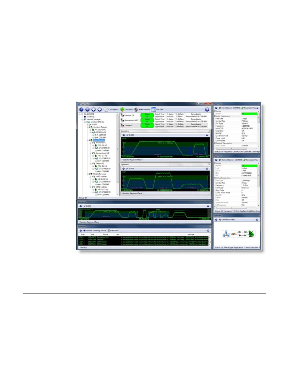
The VMS ViperView display (figure 1-1) gives the operator a complete view of
a network’s configuration, the health of all network components, and current
bandwidth usage. The ViperView display is flexible and can be modified by the
operator at any time, as described in this User Guide, to optimize network
Management and Control.
Figure 1-1
VMS ViperView display
Vipersat uses IP connections between network nodes, supporting UDP connectivity. The Vipersat modem/router consists of a satellite modem with an imbedded microprocessor router, which is the interface between LAN traffic and the
satellite links that connect Remote stations to the Hub.
1-6 VMS User Guide
Page 31

MN/22156, rev 12 Product Description
The VMS has a client/server architecture, as shown in figure 1-2, with rack
servers communicating with remote client PC’s. The client/server model has a
number of advantages. The server maintains all databases in a central location
accessible to all clients. Thus, all network status updates and performance data
is stored in a single place, processed by the VMS running on the central server,
and the results are available to all clients across the network.
Through its client/server architecture, the VMS supports centralized management, control, and distribution of data, alarms, and events. The VMS also simultaneously supports multiple clients, network management, and complete
visibility of the entire network operation.
VMS Features
The VMS network management software has the following features:
• System Configuration
• Network Status Displays (automatic and manual)
• Dynamic Bandwidth Management
• Guaranteed Bandwidth Reservations
• Switching Operations, including:
• Point-to-Point Switching
• Advanced Modulation/Code Switching
• Out-of-Band Switching
• Integrated Circuit Scheduler
• Diagnostics Monitor and Control (automatic and manual)
• Alarm Processing
• Run Authorization via USB Crypto-Key
• Optional Management Security
• Optional VMS and Critical Hardware Redundancy
• Statistics Gathering (automatic and manual)
• Report Generation
• Network Administrator Mode
• Remote Access via Local LAN or Internet/Intranet
• Dual-level User Account Authorization
Chapter 1 - General 1-7
Page 32

Product Description MN/22156, rev 12
• Interfaces to external NMS:
• RESTful Interface
• SNMP Northbound Interface
1-8 VMS User Guide
Page 33

MN/22156, rev 12 Product Description
VMS
Client
ViperView
VMS
Vipersat Object Service
(VOS) Server
VMS
Vipersat Object Service
(VOS) Server
VMS
Client
ViperView
Redundant VMS
Servers
VMS Operation & Architecture
A Vipersat network provides Internet Protocol (IP) connections between
network nodes and supporting UDP and Multicast protocols. Vipersat satellite
networks rely on Vipersat modem/routers to provide the interface between LAN
traffic and the satellite links that connect Remote stations to the Hub.
The VMS Client (ViperView) and Server (Vipersat Object Service) architecture (figure 1-2) supports centralized management, control, and distribution of
data, alarms, and events. Network units, such as a Vipersat modem/router, while
functioning as a modulator/demodulator, also detect, analyze, and report details
on network operation to the VMS. The VMS collects, stores, analyzes, and acts
on this information to intelligently control network operation to optimize bandwidth utilization and overall network performance.
Figure 1-2
ViperView Client / Server (VOS) Relationship
The VMS management and monitoring system uses an intuitive graphic display,
as illustrated in figure 1-1. The VMS makes visible the entire network’s operation and performance. All network status and performance data is collected,
processed, and stored at the server. Any client workstation can retrieve information from the VMS server’s single, central database.
The VMS network management system displays the following information
gathered from the network modem/routers:
• System configuration
• Transmission configurations
Chapter 1 - General 1-9
Page 34

Product Description MN/22156, rev 12
• Satellite link Status
• QoS displayed as E
values for each circuit
bN0
• Switching times and connection type and duration for each circuit
• Network alarms showing health of network hardware IP and RF
connections
• Bandwidth resource allocations
• Modem, RF equipment, and VSAT station management
The network map displays an integrated view of the entire network including all
nets, subnets, equipment, and equipment interconnections. The user can doubleclick on an icon to display its status information and/or sub-components. Rightclicking on an icon displays a drop-down menu allowing the operator to issue
commands, change configurations, or change the unit’s state, as applicable.
The colors associated with each icon, as shown in the display illustrated in
figure 1-1, reflect the current status condition of the network component or its
sub-components:
• Green = Okay
• Red = Alarm
• Gray = Disconnected (offline) as the result of missing three consecutive
PLDMs and not responding to the recovery process
All devices, networks, and carriers displayed by ViperView share the same
color scheme for indicating their health in the network, giving the operator realtime at-a-glance network health status.
The VMS provides operator notification in the event of network alarms. This
notification can be in the form of both visual and audible alerts. The VMS also
maintains a log of all network activity, making use of analysis and network
trouble-shooting information readily available.
1-10 VMS User Guide
Page 35

MN/22156, rev 12 Product Description
New in this Revision
v 3.11.3 Release
Carrier Presence Switching
Carrier Presence Switching (CPS) allows the VMS to autonomously manipulate
carriers through presence-based distributions within the satellite bandwidth
pools. This switching type is determined by the presence or absence of carriers,
executing bandwidth shifts governed by divisional carrier distribution and individual policy settings. CPS is a Hertz defined switching method in which a
carrier may occupy a large segment of bandwidth even with little to no traffic
load on the terminal.
See the Release Notes for additional information on the VMS v3.11.3 product
release.
v3.12.0 Release
Preemptive Bandwidth Pool Management
Bandwidth Exclusion zones provide the capability of blocking segments of
dSCPC pool bandwidth through an external interface. The exclusion management allows external applications to request a start and stop frequency segment
of bandwidth for temporary use of foreign carrier overlays within the pools.
The assignment of an exclusion zone exclusively blocks, or “masks”, a region
of bandwidth, forcing any dynamic carrier to move out of that region during
foreign carrier presence. The deletion of the exclusion clears, or “unmasks”, the
specified region, freeing the bandwidth and resuming all normal dSCPC usage.
This masking of the pools prevents carrier interface of shared satellite capacity
between dynamic and externally managed carriers during preemptive periods of
time.
An active exclusion provides bandwidth segmentation with visual indication,
and manual control along with external management.
RESTful Interface
The new VMS RESTful interface is a Web Services API that adheres to the
REST (Representational State Transfer) principles. This interface provides a
high level control of VMS element structures via document-addressable URL’s
simplifying and standardizing on an external application interface, such as to/
from a network management system (NMS). The following are some generic
details of each of these elements.
Chapter 1 - General 1-11
Page 36

Product Description MN/22156, rev 12
The different HTTP request methods used for transactions:
• GET – request method that returns the current state of the element.
• PUT – request method that updates the state of the element.
• POST – request method that creates a new instance of the element type.
• DELETE – request method that deletes an element.
Note that this v3.12 VMS release provides only a small subset of calls supporting exclusion bandwidth control. For more information on the RESTful interface, refer to the VMS REST ICD.
CDM-760 Device Driver
A new Vipersat SNMP device driver has been added to the VMS to support
Out-of-Band switching services for the CDM-760 modem/router.
Operations Monitor
The Operations Monitor is a modeless pop-up dialog used to present the status
of a pending operation which would ordinarily block the VMS client (ViperView) from initiating any additional actions until the previous operation is
concluded. The user can now execute multiple commands simultaneously
without blocking occuring in the client.
A window pane for each pending operation displays a description which can
include the name of the associated external unit, or the number of associated
external units if there are more than one. The initiation time followed by the
number of seconds since the operation started is also displayed. In addition,
some operations have a progress message.
For example, a pending image upgrade indicates how many packets have
been transmitted so far, as well as the total number of packets. When the
operation is completed, a green or red icon appears to indicate success or
failure.
Multi-Select
The client Multi-Select feature allows much more control and flexibility for an
operator to modify multiple sites, units, or devices at random or contiguously
for different types of operations by holding the Shift or Ctrl key during selection. The example below shows multiple sites selected presenting either Diagnostic Revert or Reset control. This type of selection control facilitates grouped
operations, expediting many different processes.
1-12 VMS User Guide
Page 37

MN/22156, rev 12 Product Description
Drag-and-Drop
The option to Drag-and-Drop a modem/router unit onto an antenna is now
supported in the Antenna view, automatically binding all mod/demods to
their associated up/down converters.
Block Active Demodulator
In previous versions of the VMS, an operator was not allowed to mark an active
“Allocated” demodulator for non-operation. The demodulators could only be
blocked during a non-active state, making maintenance of a unit difficult. This
new version allows an active demodulator to be pre-blocked for out-of-service
or decommissioning.
Codecast Image Upgrade
The modem/router application image upgrade feature now supports multiple
methods of transfer: consecutive, concurrent, and codecast. The new Codecast
feature, when used in conjunction with Multi-Select (see above), provides the
means to perform a software upgrade to multiple like units by reliably multicasting a single file transaction.
Codecast works with CDD-880 and CDM-840 units running v1.5.2.x or greater.
Spectrum View Animation
There are new controls for the Satellite Spectrum view to help increase response
time when displaying this window while remote accessing. The animation of
carriers typically requires increased bandwidth on the remote connection to the
VMS server, which could cause a slower response time in ViperView. The
operator now has the ability to adjust the refresh rate of the RF display—setting
it to Fast, Slow, or Off—so that this effect is minimized. An Automatic setting
option disables animation during Remote Desktop (RDP) connections and
provides Fast refresh for direct ViperView access.
Chapter 1 - General 1-13
Page 38

Product Description MN/22156, rev 12
Dual Speed Status Update Timer
The Vipersat Manager Status Update Message timer now provides two timeout
parameters, one for SCPC and one for ECM. The new timer for ECM is used in
cases where multiple remotes remain in ECM and, by slowing the status
message reporting, will reduce channel contention.
The ECM timer only works with CDD-880 and CDM-840 units running
v1.5.2.x or greater; all other units work as normal using the SCPC timer.
Event View Auto Scroll Control
The automatic scroll function in the Event View can be enabled or disabled by
the user to facilitate the viewing of log entries. Auto Scroll On ensures the latest
entry is visible in the display window. Auto Scroll Off gives the user manual
scroll control.
See the Release Notes for additional information on the VMS v3.12.0 product
release.
1-14 VMS User Guide
Page 39

MN/22156, rev 12 Co n ta ct I n f or m a t io n
Contact Information
Customer Support
Contact Comtech EF Data Customer Support for information or assistance with
product support, service, or training on any product.
Tel: +1.240.243.1880
+1.866.472.3963 (toll-free USA)
Comtech EF Data Headquarters
Comtech EF Data Corporation
2114 West 7th Street
Tempe, Arizona 85281
USA
+1.480.333.2200
www.comtechefdata.com
Reader Comments / Corrections
If the reader would like to submit any comments or corrections regarding this
manual and its contents, please forward them to a Comtech Customer Support
representative. All input is appreciated.
Chapter 1 - General 1-15
Page 40

Co n t a ct I n f or m a t i o n MN/22156, rev 12
{ This Page is Intentionally Blank }
1-16 VMS User Guide
Page 41

VMS INSTALLATION
General
For specifications for the minimum recommended hardware and software platform configuration to host the VMS, please refer to the VMS Release Notes for
the version of software that will be installed. Both Server and Client configurations are provided.
The VMS software is installed using an Installation Wizard. Depending on the
desired setup, installation can be performed with the full set of files (both client
and server), client-only files, or server-only files. The Wizard guides the
installer through the installation process and provides all necessary information
to complete typical, compact, and custom installations.
C
HAPTER
The same procedure for installation of the VMS on a server is used for both
stand-alone and redundant configurations.
Caution: Installing VMS on non-recommended hardware or operating system
will void the support warranty. Also, VMS must be installed on a
dedicated server to retain support warranty.
Caution: Vipersat strongly recommends against running any kind of anti-virus
program on the VMS server. Instead, all Microsoft Windows Updates
should be installed as they become available. However, the
Automatic Updates function in Microsoft Windows must be properly
set to avoid possible disruption of the VMS and the Vipersat network.
Please see the information below.
Chapter 2 - VMS Installation 2-1
Page 42

Ge n er al MN/22156, rev 12
VMS Server - MS Windows Update Setting
The Microsoft Windows Update feature provides a selection of configuration
settings. The default setting, Automatic, will automatically download and install
Windows updates. Typically, this process includes an automatic reboot of the
server to implement the updates.
A VMS server with the default setting and an active connection to the Internet is
susceptible to experiencing an automatic reboot that may adversely impact
Vipersat network functions.
Vipersat therefore strongly recommends that the Windows Update configuration NOT be set to Automatic. This feature should be set to either of the two
selections below:
• Check for updates, but let me choose whether to download and install
them
• Download updates, but let me choose whether to install them
1. Access the Windows Update configuration window from the Start Menu by
choosing Windows Update from either the All Programs menu or the
Control Panel.
Figure 2-1
Windows Update window
2. From the left panel menu, select Change Settings. The window shown in
figure 2-2 will appear.
2-2 VMS User Guide
Page 43

MN/22156, rev 12 Gen e r al
Figure 2-2
Windows Update, Change Settings window
3. Select the update setting from the drop-down menu, then click OK.
Types of Installation
The VMS can be installed in three different configurations:
1. On a single VMS server; Vipersat Management System Service.
2. On two or more (N:1) VMS servers in the optional fault-tolerant, redundant
configuration; Vipersat Management System Service.
3. On a client workstation; ViperView User Interface.
Server installations can be performed as either:
• Clean Installation - An installation on a server that has not previously
operated as a VMS server, or that has had its hard drive re-formatted. With
no existing network database, a full network configuration (Chapter 3,
“VMS Configuration”) must be performed following installation.
Chapter 2 - VMS Installation 2-3
Page 44

Ge n er al MN/22156, rev 12
NOTE
NOTE
• Upgrade Installation - An installation on a server that has previously
been installed as a VMS server in a Vipersat network, operating with a
previous version of VMS. An existing v3.7 or later network database will
be automatically converted during installation.
Warning: When upgrading from v3.6.x, the existing network database is
incompatible and will NOT be automatically converted
installation. Contact a service representative prior to attempting this
type of upgrade. He/she will guide the operator in the necessary
transition process to prevent loss of network configuration.
Note: It is NOT RECOMMENDED to run ViperView on the same machine as
the VOS. Therefore, installing and running the VMS Client software
component on a workstation that is separate from the VMS server is
preferred.
Note: Upgrade installations require a file (.vku) update for the Vipersat USB
Crypto-Key to be compatible with the new version of VMS software. An
incompatibility will prevent the VMS from running on the server. See subsections “Prepare for Crypto-Key Updating (Upgrade)” on page 2-9, and
“Update USB Crypto-Key (Upgrade)” on page 2-15 for update instructions.
during
Redundant Server Upgrade
For a redundant VMS configuration, perform the upgrade on the Standby server
first. This will allow the installation of the new software and database creation
to be verified without losing VMS service. If successful, continue the upgrade
by doing the following:
• Deactivate the Active (Primary) server.
• Activate the Standby (Secondary) server.
• Perform upgrade installation on the now deactivated server.
This method provides a seamless upgrade with no VMS downtime.
The installation instructions in the following section include special instructions
for each of these various installation types.
Caution: Failure to note and follow the instructions for the intended network
configuration may cause the VMS installation to fail or to operate
erratically.
2-4 VMS User Guide
Page 45

MN/22156, rev 12 Pr e p a r e S e r ve r f o r V M S I ns t a l la t i o n
Prepare Server for VMS Installation
The Vipersat Management System Server software should be installed on a
high-performance, industry-standard computer running the Microsoft Windows
Server 2008 or later operating system.
If not already done, perform the following tasks before proceeding with installation of VMS on the server:
• Limit DEP (Data Execution Prevention) — see following section.
• Create a user account in the Active Directory (example: VMS).
• Add the VMS user to the DCOM Limits.
• Reboot the server before continuing with the VMS installation.
Limit DEP (Data Execution Prevention)
DEP (Data Execution Prevention) is a service, available on some CPUs, which
will actively block a virus or program which it determines acts like a virus.
Without limiting the action of the DEP feature to essential Windows programs
and services, this procedure will prevent DEP from blocking the actions associated with VMS.
Use the following procedure to make certain that this feature is limited to essential Windows programs only.
1. From the server’s Start menu, open the System control panel located at
Start > Control Panel > System, as shown in figure 2-3.
2. Click on Advanced system settings to display the System Properties dialog
page shown in figure 2-4.
Chapter 2 - VMS Installation 2-5
Page 46

Pr e p a re S e r ve r f o r V MS I n s t a ll a t i on MN/22156, rev 12
Figure 2-3
Figure 2-4
System Control Panel
System Properties—Advanced tab
3. In the Performance box on the Advanced tab, click the Settings button,
then click the Data Execution Prevention tab to display the dialog shown in
figure 2-5.
2-6 VMS User Guide
Page 47

MN/22156, rev 12 Pr e p a r e S e r ve r f o r V M S I ns t a l la t i o n
NOTE
Figure 2-5
DEP tab
4. Select the Turn on DEP for essential Windows Programs and services
only radio button. If the CPU processor does not support DEP, this radio
button will be greyed out and unavailable.
5. Click the OK button to complete this procedure.
This action limits DEP to protecting only essential Windows programs without
interfering with any other applications.
Back Up VMS Database (Upgrade)
For VMS upgrades, it is recommended that the current VMS database be backed
up prior to installing the new version of VMS. This precaution will allow for the
current database to be restored in the event that the new install fails.
Note: This database backup can only be restored on the current VMS version.
Chapter 2 - VMS Installation 2-7
It is not compatible with the new VMS version.
Page 48

Pr e p a re S e r ve r f o r V MS I n s t a ll a t i on MN/22156, rev 12
Should the new VMS installation fail, the fall-back procedure would be to reinstall the previous version of VMS, then restore the database with the backup.
A successful installation of the new VMS will result in a new database. This
new database should immediately be backed up, and any previous database
backups should be removed from the server to avoid compatibility issues.
1. Right-click on the VMS Server icon and select Backup from the drop-down
menu (figure 2-6).
Figure 2-6
Backup Command, VMS Server
2. Enter the Name for the backup file and select the directory location for
saving the file from the Save As dialog window that opens (figure 2-7).
2-8 VMS User Guide
Page 49

MN/22156, rev 12 Pr e p a r e S e r ve r f o r V M S I ns t a l la t i o n
Figure 2-7
VMS Backup Save As dialog
Prepare for Crypto-Key Updating (Upgrade)
Each time the VMS software is upgraded to a new version, the Vipersat USB
Crypto-Key must be updated in order for the VMS to run on the server. An
update utility, vms-key-update.exe, is used for this purpose and is obtained by
contacting Vipersat CTAC (“Contact Information”). The following information
will be required:
• Key Serial Number
• Key Licensing
Both of these items can be obtained from ViperView using the following
method:
1. Click on the Server icon in the menu bar and select Properties, as shown in
figure 2-8.
2. The serial number is listed in the Properties dialog that opens. Record this
number, or capture it as a screen shot graphic, then close the window.
Chapter 2 - VMS Installation 2-9
Page 50
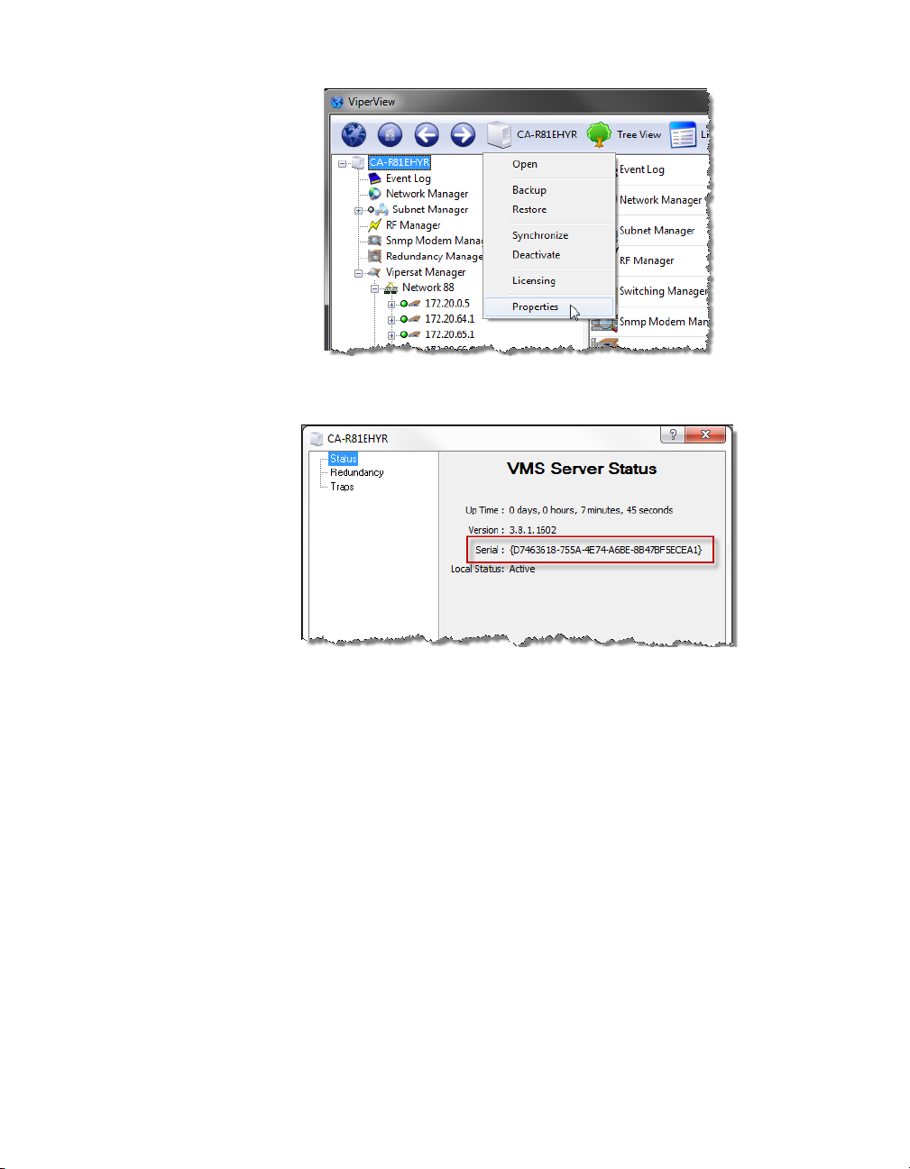
Pr e p a re S e r ve r f o r V MS I n s t a ll a t i on MN/22156, rev 12
Figure 2-8
Figure 2-9
Serial Number, Server Properties dialog
Server Menu, ViperView
3. Again click on the Server icon, and select Licensing.
The Licensing Information dialog that opens (figure 2-10) contains a listing
of the Authorized Services associated with this key.
2-10 VMS User Guide
Page 51

MN/22156, rev 12 Pr e p a r e S e r ve r f o r V M S I ns t a l la t i o n
Figure 2-10
Licensing Information, Crypto-Key
4. Perform a screen capture and save the graphic file. The licensing list may
extend beyond the window view, as shown in the example above; if this is
the case, use the scroll bar and capture a second screen.
Do not perform the key update at this time. The procedure will be executed in a
later sub-section (“Update USB Crypto-Key (Upgrade)” on page 2-15).
Stop Previous VMS Version (Upgrade)
If there is an earlier version of VMS installed and running on the server, use the
following procedure to stop VMS before proceeding with the new installation.
For VMS installation on a server that does NOT have a previous version of
VMS installed, skip this section and proceed to the section “VMS Server Installation” on page 2-16.
Caution: If a prior version of VMS is installed and running on the server, you
must first stop, then uninstall, this prior version as described in this
and the following procedure.
1.
Right-click in the Windows status bar and select Start Task Manager from
the pop-up menu. The Windows Task Manager window will appear.
2. From the Processes tab, scroll down the list to find the three VMS processes
that are running—VConMgr.exe, ViperView.exe, and VOS.exe, as shown in
figure 2-11.
Chapter 2 - VMS Installation 2-11
Page 52

Pr e p a re S e r ve r f o r V MS I n s t a ll a t i on MN/22156, rev 12
Note: The “Show processes from all users” checkbox at the bottom of the
window must be selected in order for the VOS.exe process to appear in the
list.
Figure 2-11
Windows Task Manager, Processes tab
3. Select each process and click on the End Process button. A Task Manager
Warning dialog will appear (figure 2-12)—click on the Yes button to terminate the process.
2-12 VMS User Guide
Page 53

MN/22156, rev 12 Pr e p a r e S e r ve r f o r V M S I ns t a l la t i o n
Figure 2-12
Task Manager Warning dialog
4. After each of the three processes have been terminated, close the Task Manager window then re-open it to confirm that the processes are no longer running.
5. Once the Vipersat Management System service has been stopped, uninstall
the previous version of VMS from the server as described in the following
section.
Uninstall Previous VMS Version (Upgrade)
1. Uninstall the previous version of VMS by selecting Programs and Features
from the server’s Control Panel, as shown in figure 2-13.
Chapter 2 - VMS Installation 2-13
Page 54

Pr e p a re S e r ve r f o r V MS I n s t a ll a t i on MN/22156, rev 12
Figure 2-13
Programs and Features Control Panel
2. Select Vipersat Management System and click the Uninstall button
(figure 2-14).
2-14 VMS User Guide
Page 55

MN/22156, rev 12 Pr e p a r e S e r ve r f o r V M S I ns t a l la t i o n
Figure 2-14
VMS, Uninstall Program
3. Perform an uninstall of any Driver Packs that have been installed since the
last VMS installation.
4. Close the Programs and Features window.
Update USB Crypto-Key (Upgrade)
Execute the procedure for updating the Vipersat USB Crypto-Key that was
provided by Vipersat CTAC {refer to the section “Prepare for Crypto-Key
Updating (Upgrade)” on page 2-9} prior to performing the VMS Server installation procedure in the following section.
CTAC will provide both the
update.exe
update utility.
If this procedure has not yet been provided, contact “Contact Information” and
update the Key before continuing with installation.
Chapter 2 - VMS Installation 2-15
vipersat.vku update file and the vms-key-
Page 56
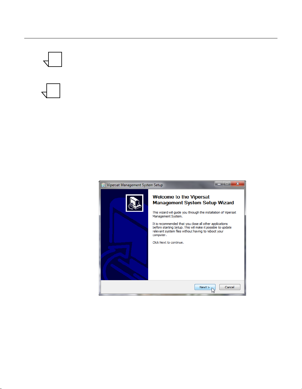
VM S S e rv e r I n s ta l l a ti o n MN/22156, rev 12
NOTE
NOTE
VMS Server Installation
Note: If this is a clean installation, ensure that the Vipersat USB Crypto-Key is
not plugged in at this time. The installation process will install the drivers
necessary for the key. The key will be inserted later when the VMS is
ready to be started (“Verify Server Installation” on page 2-27).
Note: For VMS Redundancy Server configurations, after installing VMS on
each of the servers as described in this section, refer to Appendix C,
“Redundancy”, for detailed instructions for configuring the redundant
servers.
1.
Locate the file VMS 3.x Core Setup.exe in the VMS distribution file set
(available from
Information”)and double-click it to start the VMS Installer.
2. After starting the VMS installer, the Vipersat Management System Setup
Wizard welcome screen, shown in figure 2-15, is displayed. Click the Next
button to continue.
www.comtechefdata.com, or from “Contact
Figure 2-15
Setup Wizard Welcome screen
3. On the License Agreement screen, shown in figure 2-16, click the I Agree
button to proceed.
2-16 VMS User Guide
Page 57

MN/22156, rev 12 VM S S e rv e r I ns t a l la t i o n
10.X
Figure 2-16
License Agreement screen
4. The VMS software is comprised of two main components, the Server component and the Client component. From the Installation Type screen shown
in figure 2-17, select the radio button for the type of installation you will be
making. For a VMS Server installation, select either Full Install or Server
Install. (The Client Install selection is for a VMS Client workstation installation.)
• Full Install - This type of installation installs both components, and
allows a local user to operate VMS locally on the server and also
remotely. This installation type requires a USB key to operate VMS.
• Server Install - This type of installation only installs the Server
component, and allows the VMS server to be operated through a remote
connection by a client—the VMS can not be operated from the local
server. This installation type requires a USB key to operate VMS.
• Client Install - This type of installation only installs the Client
component, and is used to install the VMS client on a workstation that
will be used to connect remotely to servers on the same LAN that are
running the VMS. This installation type does not require a USB key to
operate VMS.
Chapter 2 - VMS Installation 2-17
Page 58

VM S S e rv e r I n s ta l l a ti o n MN/22156, rev 12
Figure 2-17
Installation Type screen
5. Click the Next button to proceed to the VMS Setup screen.
6. The Service Configuration defaults with all three boxes checked as shown in
figure 2-18. This is the recommended configuration.
Figure 2-18
Service Configuration dialog
7. The Username for the account is auto-filled with the default entry (VMS). It
is recommended not to change this setting, unless it is necessary to match the
2-18 VMS User Guide
Page 59
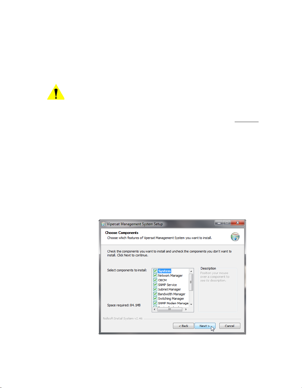
MN/22156, rev 12 VM S S e rv e r I ns t a l la t i o n
user account that was created previously (see “Prepare Server for VMS
Installation” on page 2-5).
Note: If this is an upgrade, use the same name as before.
8. If the VMS server is to operate in a Domain, enter the domain name in the
Domain field exactly as the domain is named.
Caution: Failure to have an exact match between the assigned domain name
and the domain name entered in this dialog will cause VMS to fail,
requiring re-installation.
9. The Password field is auto-filled with the default password, V1persat. Enter
a new password, if desired, to change the default setting. This password must
match the password associated with the VMS user account.
Note: If this is an upgrade of a domain account, enter the password associated with this acount.
10. Click the Next button when this dialog is complete.
11. The Choose Components dialog appears, as shown in figure 2-19. All ser-
vices are selected by default for a typical VMS installation. It is recommended that these settings not be changed, except for non-standard
installations.
Figure 2-19
Chapter 2 - VMS Installation 2-19
Choose Components dialog
Page 60

VM S S e rv e r I n s ta l l a ti o n MN/22156, rev 12
12. Click the Next button to proceed.
13. In the Choose Install Location dialog shown in figure 2-20, it is recom-
mended that the default file location be used. Click the Next button to continue.
Figure 2-20
Choose Install Location dialog
14. From the Choose Start Menu Folder dialog shown in figure 2-21, accept
the default folder name, VMS 3.x, and click the Install button to start the
installation process.
2-20 VMS User Guide
Page 61

MN/22156, rev 12 VM S S e rv e r I ns t a l la t i o n
Figure 2-21
Choose Start Menu Folder dialog
15. The installation process will begin and a green progress bar will display.
The installation process will continue and, when completed, the screen
shown in figure 2-22 will be displayed. Click the Next button.
Figure 2-22
Installation Complete screen
16. Click the Finish button to exit the VMS Setup Wizard.
Chapter 2 - VMS Installation 2-21
Page 62

VM S S e rv e r I n s ta l l a ti o n MN/22156, rev 12
NOTE
Figure 2-23
VMS Setup Wizard Finish dialog
Management Security Installation — Option
Note: The Management Security feature is not provided with standard VMS
Management Security is an optional software module for the VMS that protects
the M&C messages that pass between network modems and the VMS over
exposed LAN/WAN segments within the network.
1. Execute the VMS Management Encryption Option Setup.exe application.
2. Complete the wizard setup to finish the installation.
installations, and is available only upon request and through an authorized agent.
This feature is applicable only with encryption-capable modems.
This use of a specially programmed Crypto-Key is required.
This will open the Setup Wizard that will install the AES .dll file into the
appropriate program file directory.
This completes the installation of the VMS Management Security Option.
2-22 VMS User Guide
Page 63

MN/22156, rev 12 VM S S e rv e r I ns t a l la t i o n
NOTE
Note: If this is a stand-alone installation on a workgroup server, or an upgrade
installation, move on to the section “Verify Server Installation” on
page 2-27.
If this is an installation on a new or completely rebuilt Domain Controller,
continue with the following section, “Set Com Security for VMS”.
Set Com Security for VMS
1. From the Windows Start menu, select Settings and open up the Control
Panel, as shown in figure 2-24 below.
Figure 2-24
Control Panel
2. Select Administrative Tools and then Component Services, as shown in
figure 2-25.
Chapter 2 - VMS Installation 2-23
Page 64

VM S S e rv e r I n s ta l l a ti o n MN/22156, rev 12
Figure 2-25
Administrative Tools
3. Expand the Component Services tree until “My Computer” appears. Rightclick on My Computer and select Properties, as shown in figure 2-26.
Figure 2-26
Component Services, My Computer Menu
4. Select the COM Security tab, then the Edit Limits button under Launch
and Activation Permissions, as shown below in figure 2-27.
2-24 VMS User Guide
Page 65

MN/22156, rev 12 VM S S e rv e r I ns t a l la t i o n
Figure 2-27
Com Security, Edit Limits
5. In the Launch Permissions window, select Add as shown in figure 2-28.
Figure 2-28
Launch Permissions
Chapter 2 - VMS Installation 2-25
Page 66

VM S S e rv e r I n s ta l l a ti o n MN/22156, rev 12
6. Ensure that the Location selection is the domain, then type “VMS” in the
object names box and click the Check Names button. If the location is correct, the object name will be found and displayed underlined
, as shown by
the example in figure 2-29.
Figure 2-29
Select Users
7. Click on OK. The Launch Permissions window will display the new user
highlighted. Check all of the Allow boxes as shown in figure 2-30, then click
the OK button.
Figure 2-30
Launch Permissions with New User
This concludes setting the Component Securities on the Domain Controller.
2-26 VMS User Guide
Page 67

MN/22156, rev 12 VM S S e rv e r I ns t a l la t i o n
Verify Server Installation
This verification process utilizes the ViperView Client, and thus can only be
executed using just the server when a Full Install has been performed. For a
Server Install, verification of successful installation requires the use of a Client
workstation (see “Verify Client Installation” on page 2-33).
1. Insert the Vipersat Crypto-Key into an available USB port on the VMS
server. This key is required to run the Vipersat Management System Service
(VOS).
2. Open the Services window on the server by selecting Services from the
> Administrative Tools
menu.
Start
Figure 2-31
Services, Administrative Tools menu
3. Select Vipersat Management System from the Services list as shown in
figure 2-32, then click on Start the service.
Chapter 2 - VMS Installation 2-27
Page 68

VM S S e rv e r I n s ta l l a ti o n MN/22156, rev 12
NOTE
Figure 2-32
Vipersat Management System Service
This will start the VOS (Vipersat Object Service) process. VOS.exe will
appear in the Processes tab of the Windows Task Manager.
Note: The Vipersat Crypto-Key must be connected to the server’s USB port.
Otherwise, the attempt to start VMS will fail.
If the Start attempt fails, proceed to “VMS Service Start Failure” on
page 2-29.
4. Open the Connection Manager from the path
Connection Manager
.
Start > Programs > VMS >
The Connect dialog will appear.
Figure 2-33
Server Connect dialog
5. When using the server, accept “localhost” and click on the OK button.
When using a client machine, enter the server IP address.
2-28 VMS User Guide
Page 69

MN/22156, rev 12 VM S S e rv e r I ns t a l la t i o n
The ViperView window will appear, as shown in figure 2-34.
Figure 2-34
Successful Installation, ViperView
To verify the version of VMS that is installed, click on the on the far right of
the ViperView menu bar and select About.
For upgrade installations only
, activate the server processes and verify that the
network database configuration is accurately displayed.
VMS Service Start Failure
Should the attempt to start the VMS service fail, verify whether or not the
Crypto-Key is the cause of the failure.
1. Open the Windows Event Viewer.
Start > Settings > Control Panel > Administrative Tools > Event Viewer]
[
2. Select Applications and look through the list for the appearance of an Error
Type for
3. Double-click the event to open the Properties dialog (figure 2-36).
Vipersat Management System, as shown in figure 2-35.
Chapter 2 - VMS Installation 2-29
Page 70

VM S S e rv e r I n s ta l l a ti o n MN/22156, rev 12
Figure 2-35
Figure 2-36
Application Error, Event Viewer
Event Properties window
If the USB key is the source of the problem, contact the network administrator
or Comtech Vipersat Network Products CTAC (“Contact Information”). They
can provide either the necessary key file (.vku) update or replacement.
2-30 VMS User Guide
Page 71

MN/22156, rev 12 VM S S e rv e r I ns t a l la t i o n
If the key is not the cause of the Start failure, repeat the installation procedure
and try again. If still no success, contact Customer Support.
This completes the VMS Server installation procedure.
• For VMS Stand-alone Server configurations, proceed to Chapter 3, “VMS
Configuration”, to configure the VMS database for the satellite network.
• For VMS Redundancy Server configurations, proceed to Appendix C,
“Redundancy”, for instructions on configuring redundant servers.
Chapter 2 - VMS Installation 2-31
Page 72

VMS Client Installation MN/22156, rev 12
NOTE
NOTE
NOTE
VMS Client Installation
The Vipersat Management System Client software should be installed on a
high-performance, industry-standard workstation computer running Microsoft
Windows XP Professional or Windows 7 Professional, with current Service
Pack. For specifications for the minimum recommended VMS platform configuration, please refer to the VMS Release Notes for the version of software that
will be installed.
Note: To run the ViperGlobe application, it is necessary to have a video
graphics card that supports a minimum of 256 MB of video memory and
supports Pixel Shader Model 2.0 - 3.0 (reference NVIDIA
Card family, 7000 series or equivalent).
Dual monitors are recommended for greater viewing of multiple
windows.
TM
Graphics
The VMS Client software is installed using the same installation disk used for
the Server installation. The Installation Wizard will prompt the user for Full
Install, Server Install, or Client Install. Selection of the Client will only install
the necessary files without prompting for USB key and password. This type of
installation only installs the Client component on a workstation that will be used
to connect remotely to the server(s) on the same LAN that are running the VMS.
This installation type does not require a USB key to operate the software.
Note: The installation does not require the USB Crypto-Key as there are no
Note: The install must be done from an account with Administrator Privileges.
services running on the client workstation. This machine will require
network connections and proper security configurations to connect to the
active VMS sever.
For the VMS Client installation, follow the same procedure used for the Server
installation provided in the section “VMS Server Installation” on page 2-16.
However, in step 4., select the radial button Client Install, as shown below in
figure 2-37.
2-32 VMS User Guide
Page 73

MN/22156, rev 12 VM S C l ie n t I ns t a l la t io n
Figure 2-37
Once the installation wizard is finished, return here to continue with the following section.
Client Installation Type
Create Client Accounts
It is necessary to configure the appropriate security settings for the Client workstation to gain network access privileges to the VMS server.
Follow the procedure in Appendix G, “VMS Client Users” for setting up client
user accounts.
Verify Client Installation
After installation, verify that the VMS Client installation was successful by
running the program. The VMS Server must be running VOS, the Vipersat
Management System service (see “Verify Server Installation” on page 2-27 for
the necessary steps to start the VMS service).
1. Open the Connection Manager using the path Start > Programs > VMS >
Connection Manager
.
2. At the connection prompt in the Connect dialog, enter the IP address of the
VMS Server and click on the OK button (figure 2-38).
Chapter 2 - VMS Installation 2-33
Page 74

VMS Client Installation MN/22156, rev 12
Figure 2-38
Connect dialog
3. The ViperView window will appear, as shown in figure 2-39.
Figure 2-39
ViperView window, VMS Client
To verify the version of VMS that is installed, click on the on the far right of
the ViperView menu bar and select About.
This completes the VMS Client installation procedure.
2-34 VMS User Guide
Page 75

MN/22156, rev 12 Vi p e r Gl o b e In s ta ll a t i o n
NOTE
ViperGlobe Installation
ViperGlobe is an optional VMS application program that is installed on the
VMS Client workstation. This workstation must have the necessary supporting
video graphic hardware that is required to run this application. ViperGlobe will
install in the same directory as the VMS Client.
Note: To run the ViperGlobe application, it is necessary to have a video
graphics card that supports a minimum of 256 MB of video memory and
supports Pixel Shader Model 2.0 - 3.0 (reference NVIDIA
Card family, 7000 series or equivalent).
TM
Graphics
Installation Procedure
1. Locate the VMS 3.x Globe Setup.exe file in the VMS distribution directory
(on CD or Web download) and double-click on the file to start the installer.
This will open the Vipersat Network Globe Setup Wizard (figure 2-40) that
will install the ViperGlobe application.
Figure 2-40
Vipersat Network Globe Setup Wizard
2. Click the Next button to progress through the Setup process.
3. Specify the Start Menu Folder for locating the program shortcut. This
folder defaults to the folder that was specified for the VMS Client installation.
Chapter 2 - VMS Installation 2-35
Page 76

ViperGlobe Installation MN/22156, rev 12
Figure 2-41
Choose Start Menu Folder
4. Click the Next button to proceed to the Choose Components dialog, as
shown in figure 2-42.
Figure 2-42
Choose Components
By default, the DirectX Runtime component is selected to be installed automatically by the wizard.
2-36 VMS User Guide
Page 77
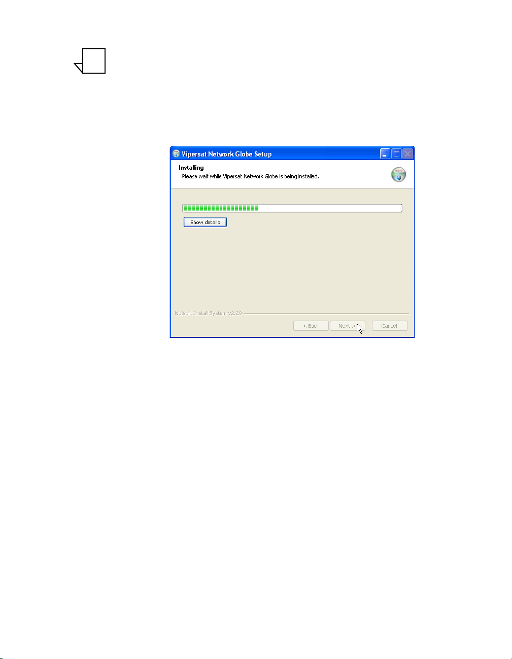
MN/22156, rev 12 Vi p e r Gl o b e In s ta ll a t i o n
NOTE
Note: This PC workstation must have internet access for this type of installation
to be successful. If internet access is not available, an offline copy of
DirectX must be installed prior to using Vipersat Globe.
5. Click the Install button to begin the installation of the application files.
The installation progress will be displayed (figure 2-43), ending with the
“Installation Complete” notification.
Figure 2-43
Installing Progress, Network Globe Setup
If DirectX is being installed, a progress dialog will open and display the status
of the download and installation processes (figure 2-44). When completed, click
Next to close this dialog and return to the Globe Setup.
Chapter 2 - VMS Installation 2-37
Page 78

ViperGlobe Installation MN/22156, rev 12
Figure 2-44
DirectX Download and Installation
6. Click on the Next button, then Finish to close the setup wizard.
Figure 2-45
Completing Vipersat Network Globe Setup
2-38 VMS User Guide
Page 79

MN/22156, rev 12 Vi p e r Gl o b e In s ta ll a t i o n
Verify ViperGlobe Installation
After installation, and with all Client connections established to the VMS
server, launch ViperGlobe:
1. Open ViperGlobe by selecting Vipersat Network Globe from the path Start
> Programs > VMS > Vipersat Network Globe
2. At the connection prompt, enter the IP address of the Active VMS server and
click on the OK button in the Connect To dialog.
3. The ViperGlobe window will appear, as shown in figure 2-46.
Note that this Globe View example shows an existing Vipersat network that
has already been configured.
.
Figure 2-46
ViperGlobe window
This completes the ViperGlobe installation procedure.
Chapter 2 - VMS Installation 2-39
Page 80

VMS Web Services Installation & Configuration MN/22156, rev 12
* Note: the Web Client PC can be local or remote
C
PC
VMS Server
SOAP Server
(Web Server)
VMS Web Services Installation & Configuration
Services Overview
The Comtech EF Data–Vipersat Network Products Group VMS Web Services
SOAP (Simple Object Access Protocol) Server offering provides an interface
for two VMS client applications and communications with the VMS (RPC
server):
• VNO (Virtual Network Operator) – Allows satellite network operators to
selectively extend network operation functions to individual customers for
monitoring and controlling their own network(s).
• ArrangeLink (AL) – A satellite communications Circuit Scheduler
interface allowing customers to schedule network resources for
applications such as video conferencing and scheduled broadcasting.
The SOAP interface runs on a web services proxy server that hosts the web
applications for VNO and AL using Internet Information Services (IIS). The
user interface for these applications is accessed using a web browser from a
client PC workstation.
The network component diagram shown in figure 2-47 reflects the recommended configuration for implementing the VMS Web Services. To minimize
latency issues, the host platform for these services should be on the same LAN
as the VMS Server. Should a network web server be locally available, it would
serve as a logical platform for the SOAP server, as shown in the diagram.
Web Client
If there is no local web server available to host these services, then the following alternative configurations can be utilized:
• If the VMS is stand-alone, then the VMS Server can host the Web
• If the VMS is redundant, then another local server must host the Web
2-40 VMS User Guide
VMS Client
P
HTTP/HTML RPC
Ethernet LAN
Figure 2-47
VMS Web Services Components
services and applications.
services and applications in order to retain true redundancy.
Page 81

MN/22156, rev 12 VMS Web Services Installation & Configuration
Requests and responses transmitted between the web application and the web
service use SOAP over HTTP protocol. The SOAP request is translated into an
RPC call into the VOS and the response is then returned to the web application.
This response is transformed into HTML and sent back to a web browser that
presents the user interface to the operator.
The ViperView client communicates directly with VOS using DCOM/RPC
protocols. ViperView is used by the Central Network Operator for administrative functions, such as creating VNO networks and other resources in the
network.
For additional information and details on the client applications, refer to the
VNO Quick Start Guide and the ArrangeLink User Guide.
SOAP Server Prerequisites
The following items are required when installing the SOAP Services onto the
server:
• Windows Server 2008 operating system recommended, with current
Service Pack.
• Microsoft Internet Information Services (IIS), current version, to provide
Web server capabilities over an intranet, the Internet, or an extranet. This
allows other PC workstations to access the web services remotely.
• Microsoft ASP.NET, current version.
• Full VMS Install.
• If a firewall is installed on the server, it must be turned off or set correctly
to allow HTTP.
• The SOAP server must be on the same LAN and have either direct access
or an Ethernet connection to the VMS server(s).
• The SOAP server must be on the same domain as the VMS server(s).
• The installer must have administrator privileges on the server.
Caution: Running SOAP Services on a machine enables that machine to act
as an HTML server which may increase its vulnerability when
connected to the Internet.
Chapter 2 - VMS Installation 2-41
Page 82

VMS Web Services Installation & Configuration MN/22156, rev 12
Server Preparation
Verify that Internet Information Services (IIS) and ASP.NET are installed and
activated (checked) on the server using the following procedure.
1. From the Start
(figure 2-48).
menu, open the Administrative Tools control panel
Figure 2-48
Administrative Tools Control Panel
2. Double-click on the Server Manager in the main panel of the window.
The Server Manager window will open (figure 2-49).
2-42 VMS User Guide
Page 83

MN/22156, rev 12 VMS Web Services Installation & Configuration
Figure 2-49
Server Manager, Add Roles
3. Click on Add Rolls to open the Add Roles Wizard window, figure 2-50.
Figure 2-50
Add Roles Wizard
Chapter 2 - VMS Installation 2-43
Page 84

VMS Web Services Installation & Configuration MN/22156, rev 12
4. Click Next to continue to the Select Server Roles page of the wizard
(figure 2-51).
Figure 2-51
Select Server Roles
5. Click to select the Web Server (IIS) role, then click Next to proceed to the
Web Server (IIS) page, as shown in figure 2-52.
2-44 VMS User Guide
Page 85

MN/22156, rev 12 VMS Web Services Installation & Configuration
Figure 2-52
Web Server (IIS) Page
6. Click Next to proceed to the Select Role Services page, figure 2-53.
Ensure that the check box for ASP.NET is as shown (selected), then click
Next.
Chapter 2 - VMS Installation 2-45
Page 86

VMS Web Services Installation & Configuration MN/22156, rev 12
Figure 2-53
Select Role Services, ASP.NET
7. The Role Services Required window will open, indicating that additional ser-
vices must be installed for ASP.NET (figure 2-54).
Click on the Add Required Role Services button to install these services.
Figure 2-54
Add Role Services Required
8. On the Select Role Services page, scroll down the services list to find IIS 6
Management Compatibility (figure 2-55).
2-46 VMS User Guide
Page 87

MN/22156, rev 12 VMS Web Services Installation & Configuration
Ensure that the check boxes for this service are as shown (selected), then
click Next.
Figure 2-55
Select Role Services, IIS 6 Management Compatibility
9. Click on the Install button in the Confirm Installation Selections page
(figure 2-56) to execute the component installations.
Chapter 2 - VMS Installation 2-47
Page 88

VMS Web Services Installation & Configuration MN/22156, rev 12
Figure 2-56
Confirm Installation Selections
10. .Review the Installation Results page (figure 2-57), then click Close to exit
the wizard.
2-48 VMS User Guide
Page 89

MN/22156, rev 12 VMS Web Services Installation & Configuration
Figure 2-57
Installation Results
11. The Server Manager window now displays Web Server (IIS) under the
Roles Summary (figure 2-58).
Close the window.
Chapter 2 - VMS Installation 2-49
Page 90

VMS Web Services Installation & Configuration MN/22156, rev 12
Figure 2-58
Server Manager, Roles Summary
Set the ASP.NET State Service to start:
1. Open the Component Services from Administrative Tools.
Select Services (Local) from the directory tree in the left window panel, as
shown in figure 2-59.
Figure 2-59
2-50 VMS User Guide
Component Services
Page 91

MN/22156, rev 12 VMS Web Services Installation & Configuration
2. Click to select the ASP.NET State Service and Start the service.
3. Right-click on the service to open the Properties dialog, figure 2-60.
Set the Startup type to Automatic and click OK.
Figure 2-60
Chapter 2 - VMS Installation 2-51
ASP.NET State Service Properties
Page 92

VMS Web Services Installation & Configuration MN/22156, rev 12
Uninstall Previous Version (Upgrade)
If a previous version of VMS SOAP Services is installed on the server, that software should be removed prior to installing the new version.
1. From the Programs and Features control panel, select the VMS SOAP
Server program and click on the Uninstall
button, as shown in figure 2-61.
Figure 2-61
Uninstall VMS SOAP Server Program
2. A confirmation dialog window will appear (figure 2-62). Click on the Uninstall button to remove the program.
2-52 VMS User Guide
Page 93

MN/22156, rev 12 VMS Web Services Installation & Configuration
Figure 2-62
Confirm Uninstall Prompt
3. Following removal, the dialog will display that the uninstall was completed
(figure 2-63). Close the window.
Figure 2-63
Uninstall Completed
Chapter 2 - VMS Installation 2-53
Page 94

VMS Web Services Installation & Configuration MN/22156, rev 12
NOTE
Installation Procedure
Note that the installation and configuration must be done using an Administrator login.
Caution: This software must be installed on a platform that is running Windows
Server 2008. Installing the SOAP Services on a computer that is not
running Windows Server 2008 will void VMS product support.
VMS Installation
The VMS Web Services SOAP Server host machine must have a VMS Full
Install performed; this is necessary in order to provide the required support files
for proper operation of the SOAP interface. However, this copy of VMS is not
used to manage the Vipersat network.
Note: A VMS Crypto-Key is not required, and these files are not called upon to
execute the client application.
Follow the installation procedure in the section “VMS Server Installation” on
page 2-16 to perform the Full Install, then return here to continue with this
procedure.
SOAP Services Installation
1. Locate the VMS 3.x SOAP Setup.exe file on the VMS distribution CD and
double-click on the file to start the installer.
This will open the VMS SOAP Server Setup Wizard (figure 2-64) that will
install the SOAP services.
2-54 VMS User Guide
Page 95

MN/22156, rev 12 VMS Web Services Installation & Configuration
Figure 2-64
VMS SOAP Server Setup Wizard
2. Click the Next button to progress through the Setup process.
3. Specify the Start Menu Folder for locating the program shortcuts. This
folder defaults to the folder that was specified for the VMS installation.
Figure 2-65
Choose Start Menu Folder
4. As shown in figure 2-66, the Installer will present a dialog requesting the
VMS SOAP Server Configuration parameters.
Chapter 2 - VMS Installation 2-55
Page 96

VMS Web Services Installation & Configuration MN/22156, rev 12
Figure 2-66
VMS SOAP Server Configuration
• VCS Port
This parameter specifies the TCP port used by the SOAP Server for the
VCS ArrangeLink application. The default port is decimal 8082. Any
available port can be specified, provided that the client VCS applications
send their request to this port.
• VNO Port
This parameter specifies the TCP port used by the SOAP Server for the
VNO application. The default port is decimal 8080. Any available port can
be specified provided that the client VNO applications send their request
to this port.
• Basic User Authentication
This check box indicates whether the Basic User Authentication is enabled
or not. If enabled, each client request contains a user name and password
in the HTTP header. The
SoapAdmin.exe utility is used to configure the
user database and privilege levels. This utility is located in the VMSinstalled directory
Program Files\Vipersat\VMS\3.0\bin.
• VMS Server IP
This parameter specifies the IP address(es) of the VMS server(s). In a
stand-alone VMS configuration, enter the one VMS server IP address. In a
redundant VMS configuration, up to nine addresses can be entered (e.g.,
for all VMS servers in the same redundancy group).
2-56 VMS User Guide
Page 97

MN/22156, rev 12 VMS Web Services Installation & Configuration
5. Enter the parameters described above, then click on the Install button.
The installation progress will be displayed, ending with the “Installation
Complete” notification (figure 2-67).
Figure 2-67
SOAP Server Installation Complete
12. Click on the Next button, then Finish to close the wizard.
13. Open the
Services Control Manager and verify that the VMS Web Services
appears in the list of services.
Figure 2-68
Services Control Manager, VMS Web Services
Chapter 2 - VMS Installation 2-57
Page 98

VMS Web Services Installation & Configuration MN/22156, rev 12
Web Applications Installation
For the installation procedure for VMS Web applications (e.g., ArrangeLink,
VNO), refer to the specific Web application user guide.
Server Configuration
After successfully completing the installation of the SOAP Services, it is necessary to perform some configuration steps on the server to assure the proper
operation of the VMS Web services and their communications with the VMS.
Set Up Log On Account
1. In the Services window, right-click on the VMS Web Services and select
Properties from the drop-down menu.
2. In the Properties dialog, click on the Log On tab, as shown in figure 2-69.
Figure 2-69
2-58 VMS User Guide
Account Set Up, VMS Web Services
Page 99

MN/22156, rev 12 VMS Web Services Installation & Configuration
3. Enter an account user name and password that matches the user account that
is running the VMS Server.
This account must be identical to (or be in the same user group as) that used
for running the VMS Server in order for the Web Services to communicate
with the VMS. If these user credentials do not match, an “Access Denied”
error will result when attempting to connect.
4. Click on OK to save this account and close the Properties dialog.
5. Start the VMS Web Services.
A single beep will indicate that the service started. Verify that the status has
changed to Running.
This completes the installation and configuration of the VMS Web Services.
This concludes the VMS Installation.
Chapter 2 - VMS Installation 2-59
Page 100

VMS Web Services Installation & Configuration MN/22156, rev 12
{ This Page is Intentionally Blank }
2-60 VMS User Guide
 Loading...