

Page 1
Vipersat Load Utility
VLoad v3.5.x
User Guide
Part Number MN/22117 Revision 1
Page 2

Page 3

Vipersat Load Utility
VLoad v3.5.x
User Guide
Part Number MN/22117
Document Revision 1
Software version 3.5.x
October 14, 2010
Page 4

COMTECH EF DATA
VIPERSAT Network Products Group
3215 Skyway Court
Fremont, CA 94539
USA
Phone: (510) 252-1462
Fax: (510) 252-1695
www.comtechefdata.com
Part Number: MN/22117
Revision: 1
Software Version 3.5.x
©2010 by Comtech EF Data, Inc. All rights reserved. No part of this document may be copied or
reproduced by any means without prior written permission of Comtech EF Data.
Comtech reserves the right to revise this publication at any time without obligation to provide
notification of such revision. Comtech periodically revises and improves its products and
therefore the information in this document is subject to change without prior notice. Comtech
makes no warranty of any kind with regard to this material, including but limited to the implied
warranties of merchantability and fitness for a particular purpose. No responsibility for any errors
or omissions that may pertain to the material herein is assumed. Comtech makes no
commitment to update nor to keep current the information contained in this document.
All products, names and services are trademarks or registered trademarks of their respective
companies.
Page 5

Printed in the United States of America
Document Revision History
Revision Date Description
0
7/18/08
Revisions for software version 3.4.x product release.
Document part number changed from 22117 to MN/22117.
New features:
Modem Support: Modem model SLM-5650A.
Set Preferences: New Digicast mode option available for Digicast networks.
1
10/14/10
Revisions for software version 3.5.x product release.
New features:
Modem Config File: Compatibility with VMS data file type; Write base modem
parameters Put option for Streamload1.
Set Preferences: New Unrestricted mode option available for Put file
validation inhibit.
Codecast: Cancel sends abort command to modem; New Send Codecast
Termination reset option.
Page 6

{ This Page is Intentionally Blank }
Page 7

Table of Contents
Chapter 1
General
How to Use This Manual . . . . . . . . . . . 1-1
Manual Organization . . . . . . . . . . . . 1-1
Chapter 1 — General . . . . . . . . . . 1-1
Chapter 2 — VLoad Installation . . . . . 1-1
Chapter 3 — Using VLoad in Vipersat Mode
1-2
Chapter 4 — Using VLoad in Digicast Mode
1-2
Appendix A — Glossary . . . . . . . . . 1-2
Conventions and References . . . . . . . . 1-2
Product Description . . . . . . . . . . . . . . 1-4
Introduction . . . . . . . . . . . . . . . . . 1-4
VLoad Features . . . . . . . . . . . . . . . 1-4
New in this Release . . . . . . . . . . . . . 1-5
Customer Support . . . . . . . . . . . . . . . 1-6
Contact Information . . . . . . . . . . . 1-6
Reader Comments / Corrections . . . . 1-6
Chapter 2
VLoad Installation
System Requirements. . . . . . . . . . . . . 2-1
Using VLoad with Windows Firewall. . . . . 2-1
Installing VLoad . . . . . . . . . . . . . . . . 2-2
Copying the VLoad File Set . . . . . . . . . 2-2
Using the Installation Wizard . . . . . . . . 2-3
Destination Location . . . . . . . . . . . 2-4
Select Start Menu Folder . . . . . . . . 2-5
Create a Desktop Icon . . . . . . . . . . 2-6
Ready to Install . . . . . . . . . . . . . 2-7
Completing Installation of VLoad . . . . 2-8
Chapter 3
Using VLoad — Vipersat Mode
Main Window Description . . . . . . . . . . . 3-1
About VLoad . . . . . . . . . . . . . . . . 3-2
Unit Listing / Selection Area . . . . . . . . 3-3
Mode Selection Area . . . . . . . . . . . . 3-3
File Selection Area . . . . . . . . . . . . . 3-4
File Type and Naming . . . . . . . . . . 3-4
Actions Area . . . . . . . . . . . . . . . . 3-5
Set Preferences . . . . . . . . . . . . . 3-5
Cancel . . . . . . . . . . . . . . . . . 3-7
Reset . . . . . . . . . . . . . . . . . . 3-8
Status / Progress Area . . . . . . . . . . 3-10
Progress Bar Color Code . . . . . . . 3-10
Set Defaults / Clear . . . . . . . . . . 3-12
View Log . . . . . . . . . . . . . . . 3-13
Exit . . . . . . . . . . . . . . . . . . 3-14
Image Selection . . . . . . . . . . . . . . . 3-15
Saving Images to Units . . . . . . . . . . 3-15
Image 1 and Image 2 . . . . . . . . . 3-16
Existing Image (Unchecked) . . . . . 3-16
Special Base Modem Considerations . . 3-16
Starting VLoad . . . . . . . . . . . . . . . . 3-17
Unit Listing and Selection . . . . . . . . . . 3-18
Unit Information . . . . . . . . . . . . . 3-18
Adding Units . . . . . . . . . . . . . . . 3-19
Add . . . . . . . . . . . . . . . . . . 3-19
Add All . . . . . . . . . . . . . . . . 3-20
Removing Units . . . . . . . . . . . . . . 3-21
Refresh . . . . . . . . . . . . . . . . . . 3-21
Order of the List . . . . . . . . . . . . . 3-22
Application Mode . . . . . . . . . . . . . . . 3-23
File Selection . . . . . . . . . . . . . . . 3-23
Actions . . . . . . . . . . . . . . . . . . 3-24
Get Application . . . . . . . . . . . . 3-25
Put Application / Codecast Application 3-27
Put FAST Code . . . . . . . . . . . . 3-30
Configuration Mode . . . . . . . . . . . . . . 3-32
File Selection . . . . . . . . . . . . . . . 3-32
Actions . . . . . . . . . . . . . . . . . . 3-33
Get Configuration . . . . . . . . . . . 3-34
Put Configuration / Codecast Configuration
3-36
Edit Param File . . . . . . . . . . . . 3-38
Base Modem Mode . . . . . . . . . . . . . . 3-39
File Selection . . . . . . . . . . . . . . . 3-39
Actions . . . . . . . . . . . . . . . . . . 3-40
Put Base Modem Image / Codecast Base
Modem Image . . . . . . . . . . . 3-41
Select Base Modem Image / Codecast
Select Base Modem Image . . . . . 3-43
ToC i
Page 8

Chapter 4
Using VLoad — Digicast Mode
Starting VLoad . . . . . . . . . . . . . . . . 4-1
Digicast Media Router Remote Commander . 4-3
Digicast Receivers Area on the Remote
Commander . . . . . . . . . . . . . . . . 4-4
Adding a Receiver into Inventory . . . . 4-5
Option Buttons Area on the Remote
Commander . . . . . . . . . . . . . . . . 4-6
Preferences Dialog . . . . . . . . . . . 4-6
Configuration Dialog . . . . . . . . . . . 4-7
Transfer Status Area on the Remote
Commander . . . . . . . . . . . . . . . . 4-8
Actions Area on the Remote Commander . 4-9
Reset . . . . . . . . . . . . . . . . . . 4-9
Tuner Setting Update . . . . . . . . . 4-11
Firmware Update . . . . . . . . . . . 4-15
PID Update . . . . . . . . . . . . . . 4-16
Appendix A
Glossary
. . . . . . . . . . . . . . . . . . . . . . . A-1
Index
. . . . . . . . . . . . . . . . . . . . .Index-1
ii VLoad User Guide
Page 9

List of Figures
Chapter 2 Figures
Figure 2-1 VLoad File Set example. . . . . . . . . 2-2
Figure 2-2 VLoad Installation File . . . . . . . . . . 2-3
Figure 2-3 VLoad Setup Wizard, Initial window 2-3
Figure 2-4 Select Destination Location, VLoad
Setup . . . . . . . . . . . . . . . . . . . . . . . . . . 2-4
Figure 2-5 Select Start Menu Folder, VLoad Setup
2-5
Figure 2-6 Create Desktop Icon, VLoad Setup 2-6
Figure 2-7 Ready to Install dialog, VLoad Setup. .
2-7
Figure 2-8 Completing Installation, VLoad Setup .
2-8
Chapter 3 Figures
Figure 3-1 VLoad Main Window, Functional Areas
3-2
Figure 3-2 VLoad Pull-Down Menu . . . . . . . . . 3-2
Figure 3-3 About VLoad window . . . . . . . . . . . 3-3
Figure 3-4 VLoad Preferences dialog . . . . . . . 3-5
Figure 3-5 Put Streamload Error . . . . . . . . . . . 3-7
Figure 3-6 Put Reset Request dialog . . . . . . . 3-8
Figure 3-7 Codecast Reboot dialog. . . . . . . . . 3-8
Figure 3-8 Codecast Application (Put) in Progress
3-11
Figure 3-9 View Log window . . . . . . . . . . . . . 3-14
Figure 3-10 VLoad Utility, Initial Window. . . . 3-17
Figure 3-11 Unit Listing / Selection box, InfoTip
displayed . . . . . . . . . . . . . . . . . . . . . . 3-18
Figure 3-12 Unit Information window. . . . . . . 3-19
Figure 3-13 Add New IP Address dialog . . . . 3-19
Figure 3-14 New IP Address Added . . . . . . . 3-20
Figure 3-15 Add All dialog. . . . . . . . . . . . . . . 3-20
Figure 3-16 Progress Status, Unit Refresh . . 3-22
Figure 3-17 Application Mode Selection . . . . 3-23
Figure 3-18 Application File Selection. . . . . . 3-24
Figure 3-19 Acquiring Application Image from
Website . . . . . . . . . . . . . . . . . . . . . . . 3-24
Figure 3-20 Get Application dialog . . . . . . . . 3-25
Figure 3-21 Get Application dialog, Advanced 3-26
Figure 3-22 Get Application Progress Status 3-27
Figure 3-23 Get Completed, File Not Saved . 3-27
Figure 3-24 Put Application / Codecast Application
dialog . . . . . . . . . . . . . . . . . . . . . . . . . 3-28
Figure 3-25 Put Application dialog, Image Selection
3-29
Figure 3-26 Put FAST Code dialog . . . . . . . . 3-30
Figure 3-27 Event Log display for Get and Put
Application . . . . . . . . . . . . . . . . . . . . . 3-31
Figure 3-28 Configuration Mode Selection . . 3-32
Figure 3-29 Configuration Parameter File Selection
3-33
Figure 3-30 Get Configuration dialog . . . . . . 3-34
Figure 3-31 Get Configuration Progress Status . .
3-35
Figure 3-32 Save As dialog, Configuration File . . .
3-35
Figure 3-33 Successful Get Configuration Status .
3-36
Figure 3-34 Put Configuration / Codecast
Configuration dialog . . . . . . . . . . . . . . 3-36
Figure 3-35 Parameter Editor window . . . . . . 3-38
Figure 3-36 Base Modem Mode Selection . . 3-39
Figure 3-37 File Selection Browse Button . . . 3-40
Figure 3-38 Acquiring Base Modem Image from
Website . . . . . . . . . . . . . . . . . . . . . . . 3-40
Figure 3-39 Put Base Modem Image / Codecast
Base Modem Image dialog . . . . . . . . 3-41
Figure 3-40 Select Base Modem Image / Codecast
Select Base Modem Image dialog . . . 3-44
Chapter 4 Figures
Figure 4-1 VLoad Utility, Initial Window . . . . . . 4-2
Figure 4-2 VLoad Preferences dialog . . . . . . . 4-2
Figure 4-3 VLoad Main Window, Digicast Mode 4-3
Figure 4-4 Digicast Receivers Listing / Selection box
4-4
Figure 4-5 Digicast Add Device dialog . . . . . . 4-5
Figure 4-6 Digicast Option Buttons . . . . . . . . . 4-6
Figure 4-7 VLoad Preference dialog . . . . . . . . 4-6
Figure 4-8 Digicast Transfer Settings dialog . . 4-7
Figure 4-9 Transfer Status, In Progress . . . . . 4-8
Figure 4-10 Transfer Status, Complete . . . . . . 4-8
Figure 4-11 Digicast Actions box. . . . . . . . . . . 4-9
Figure 4-12 Digicast Reset dialog . . . . . . . . . 4-10
LoF iii
Page 10

Figure 4-13 Digicast Tuner Setting Update dialog
4-11
Figure 4-14 Tuner Settings box. . . . . . . . . . . 4-12
Figure 4-15 Tuner Update Selection box . . . 4-14
Figure 4-16 Digicast Firmware Update window. . .
4-15
Figure 4-17 Digicast PID Update window . . . 4-16
Figure 4-18 PID Commands area . . . . . . . . . 4-17
Figure 4-19 PID Maintenance box. . . . . . . . . 4-18
Figure 4-20 Digicast Add PID dialog . . . . . . . 4-19
iv VLoad User Guide
Page 11

GENERAL
How to Use This Manual
This manual documents the features and functions of the Vipersat Load Utility
software application, and guides the user in how to use this product in a Vipersat network and in a Digicast network.
Workstation users, as well as network administrators and operators responsible
for the configuration and maintenance of the Vipersat satellite network, are the
intended audience for this document.
C
HAPTER
Manual Organization
This User Guide is organized into the following sections:
Chapter 1 — General
Contains VLoad product description, customer support information, and manual
conventions and references.
Chapter 2 — VLoad Installation
Covers the steps for installing the VLoad software application on a host PC/
workstation.
Chapter 1 - General 1-1
Page 12
How to Use This Manual
NOTE
Chapter 3 — Using VLoad in Vipersat Mode
Describes using VLoad for acting on the Application and Base Modem firmware as well as the Configuration parameter file for selected VMS controlled
modems.
Chapter 4 — Using VLoad in Digicast Mode
Describes using VLoad for updating the firmware and tuner and PID settings, as
well as setting transmission parameters for selected Digicast receivers.
Appendix A — Glossary
A glossary of terms that pertain to Vipersat satellite network technology.
Conventions and References
The following conventions are utilized in this manual to assist the reader:
Note: Provides important information relevant to the accompanying
text.
Tip: Provides complementary information that facilitates the
associated actions or instructions.
Caution: Provides explanatory text that notifies the reader of
Warning: Provides precautionary text that describes a potentially
possible consequences of an action.
hazardous situation. Failure to take or avoid a specified
action may result in damage to equipment.
The following documents are referenced in this manual, and provide supplementary information for the reader:
• Vipersat CDM-570/570L User Guide (Part Number MN/22125)
• Vipersat CDD-56X Series User Guide (Part Number MN/22137)
1-2 VLoad User Guide
Page 13

How to Use This Manual
• Vipersat SLM-5650A User Guide (Part Number MN-0000035)
• Vipersat Management System User Guide (Part Number MN/22156)
• Vipersat CDM-570/L, CDD-56X Parameter Editor User Guide (Part
Number MN-0000038)
• Vipersat SLM-5650A Parameter Editor User Guide (Part Number
MN-0000041)
Chapter 1 - General 1-3
Page 14

Product Description
Product Description
Introduction
VLoad, the Vipersat Load Utility, is a comprehensive tool for managing and
distributing application, configuration, and identification information for the
modem/routers in a Vipersat network.
VLoad is a stand-alone program which runs on a Microsoft Windows-based
workstation. Using VLoad, you can get (read) files from target Vipersat
modems and store the resulting data in files on your workstation. You can then
take these stored files and put (write) them to a targeted Vipersat modem.
The VLoad Utility performs many of the functions available through the Vipersat Management System (VMS) and supports VMS by allowing the system
administrator to store (backup) the application, configuration and identification
files used by every modem on a Vipersat network.
This function can be used to recover from equipment failure, for example, by
uploading the failed equipment’s configuration and application program to its
replacement from the stored files.
In addition, VLoad can distribute updated firmware to network modems as it
becomes available and update the FAST feature codes as new features are
purchased.
For detailed information on the VMS program, refer to the Vipersat Manage-
ment System User Guide.
VLoad Features
The VLoad utility software has the following features:
• Transmits (Put) and/or Retrieves (Get) an application image (firmware) to/
from Vipersat units.
• Transmits (Put) a FAST Feature Code to a Vipersat unit.
• Transmits (Put) and/or Retrieves (Get) as well as Edits a configuration
(parameter) file for a Vipersat unit.
• Transmits (Put) base modem application image in binary format to one or
more target Vipersat units.
• Specifies base modem image to run upon unit reset.
1-4 VLoad User Guide
Page 15

Product Description
• Refreshes unit information such as configuration and application versions,
image versions, and FAST features.
• Supports Consecutive, Concurrent, Codecast, Digicast, and Unrestricted
preferences.
• Unit Selection List displays network units that can be added or removed
for a given action.
• Progress Area displays color-coded progress bars.
• Event logging of VLoad activity shows action taken and corresponding
results.
New in this Release
v3.5.x Release
• New Unrestricted preference setting to support modem units that do not
yet have a recognized file type; file validation is inhibited during Put
operations.
• VMS-compatible modem configuration files (.vipersat-modem-
configuration) are now accepted. This file type can be selected and
converted for Put operations, as well as created and saved with Get
operations.
• When using Streamload1 (CDM-570/L, CDD-56X) Put operations, the
parameter set can be pushed from the NP card to the base modem using the
new Write Base Modem Parameters option.
• When Put operations are performed in Codecast mode, the Cancel
command now includes a Codecast abort command that is sent to the
targeted modem(s). In addition, an abort command can be issued using the
new Send Codecast Termination setting that is available during a Reset
operation.
Chapter 1 - General 1-5
Page 16

Customer Support
Customer Support
Contact Information
Contact Comtech Vipersat Networks Customer Support for information or
assistance with product support, service, or training on any Vipersat product.
Mail: 3215 Skyway Court
Phone: 1+510-252-1462
Fax: 1+510-252-1695
Email: supportcvni@comtechefdata.com
Web: www.comtechefdata.com
Reader Comments / Corrections
If the reader would like to submit any comments or corrections regarding this
manual and its contents, please forward them to a Comtech Vipersat Customer
Support representative. All input is appreciated.
Fremont, CA 94539
USA
1-6 VLoad User Guide
Page 17

VLOAD INSTALLATION
System Requirements
VLoad can be installed on any workstation with the following minimum configuration. The Vipersat Load Utility software should be installed on an industrystandard computer workstation running Microsoft Windows 2000 or later operating system.
C
HAPTER
The minimum hardware configuration required is:
• Pentium or later (or equivalent) processor
• 128 Mbytes of RAM minimum (depending on the operating system used)
• 16 bit color or higher video capability
• Network interface card with an IP stack
For the most current system requirements, refer to the VLoad Release Notes.
Using VLoad with Windows Firewall
Depending on the Windows configuration of the host PC, security warning
messages may appear when running VLoad due to the Windows firewall that
monitors the communications passed over the network. If necessary, the firewall settings can be adjusted to eliminate these messages.
Chapter 2 - VLoad Installation 2-1
Page 18
Installing VLoad
Installing VLoad
The VLoad program can be installed in one of two ways:
• Copy the VLoad file set to the local C: drive.
This method is acceptable for Vipersat users.
• Copy the VLoad Installation file to the local C: drive and launch the
VLoad Setup Installation Wizard. The wizard guides the user in creating a
program folder accessible from the Start menu, as well as the option of
creating a shortcut for the desktop.
This method creates an xml data file and registry entries for application
data that are used by Digicast. Therefore, Digicast users should use this
installation method.
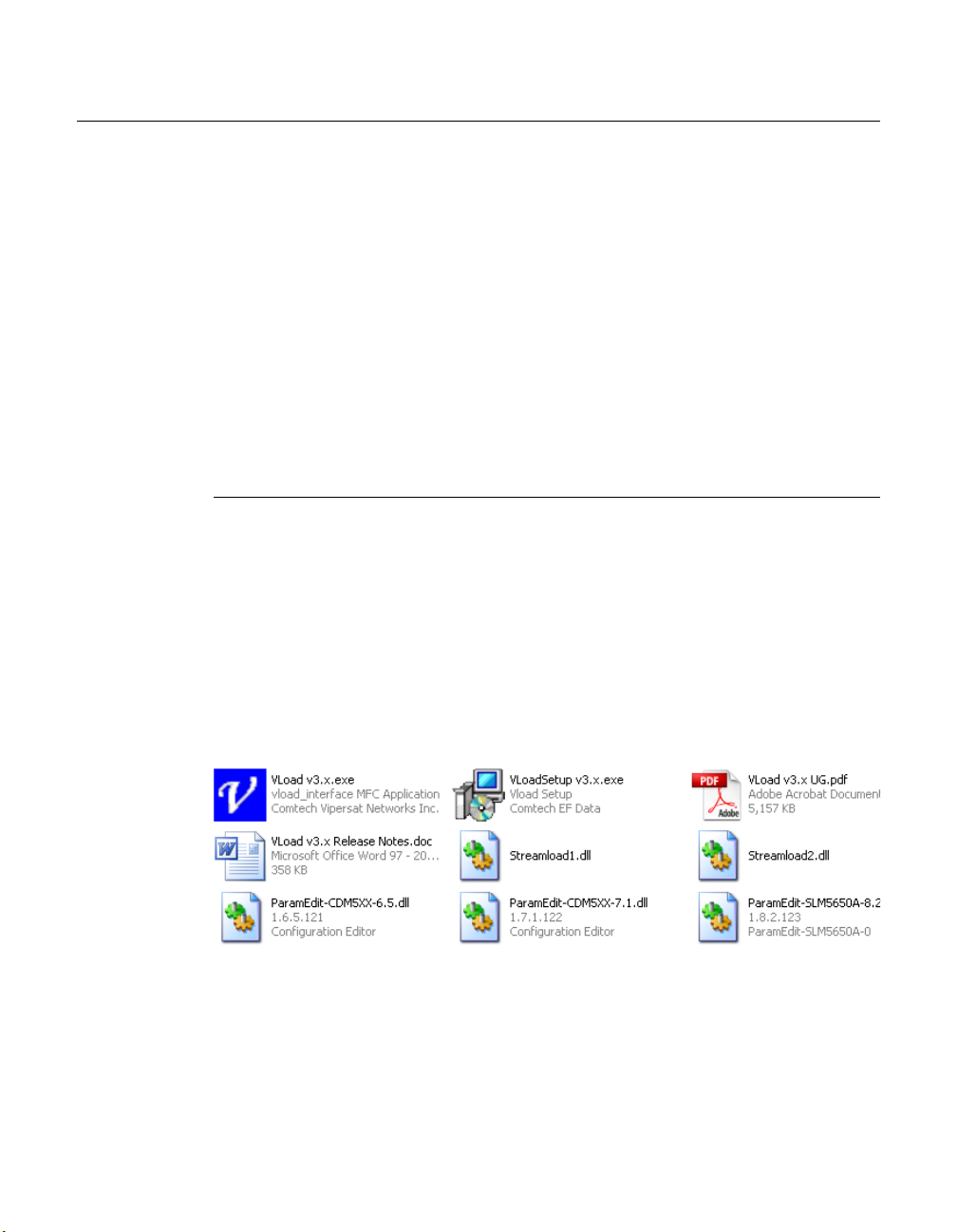
Copying the VLoad File Set
The VLoad application is distributed on a program CD with the following files:
• VLoad v3.x.exe – Application program
• VLoadSetup v3.x.exe – Program Installer
• Streamload1.dll – Streamload protocol library for CDM-570/L, CDD-56X
• Streamload2.dll – Streamload protocol library for SLM-5650A
• ParamEdit.dll – Parameter Editor library files (multiple)
• VLoad v3.x UG.pdf – Program User Guide
• VLoad v3.x Release Notes.doc
Figure 2-1
Create a new VLoad directory on the workstation that will be used to run the
VLoad utility, then copy the VLoad file set to this directory.
The VLoad.exe file runs the VLoad program and displays the graphical user
interface. The ParamEdit.dll files are utilized when editing a Vipersat modem’s
2-2 VLoad User Guide
VLoad File Set example
Page 19
Installing VLoad
configuration parameters using the capabilities described in the Vipersat
Parameter Editor User Guide.
This completes the initial installation of VLoad. During the operation of VLoad,
additional files will be created to store the parameter sets of the network
modems/routers.
Using the Installation Wizard
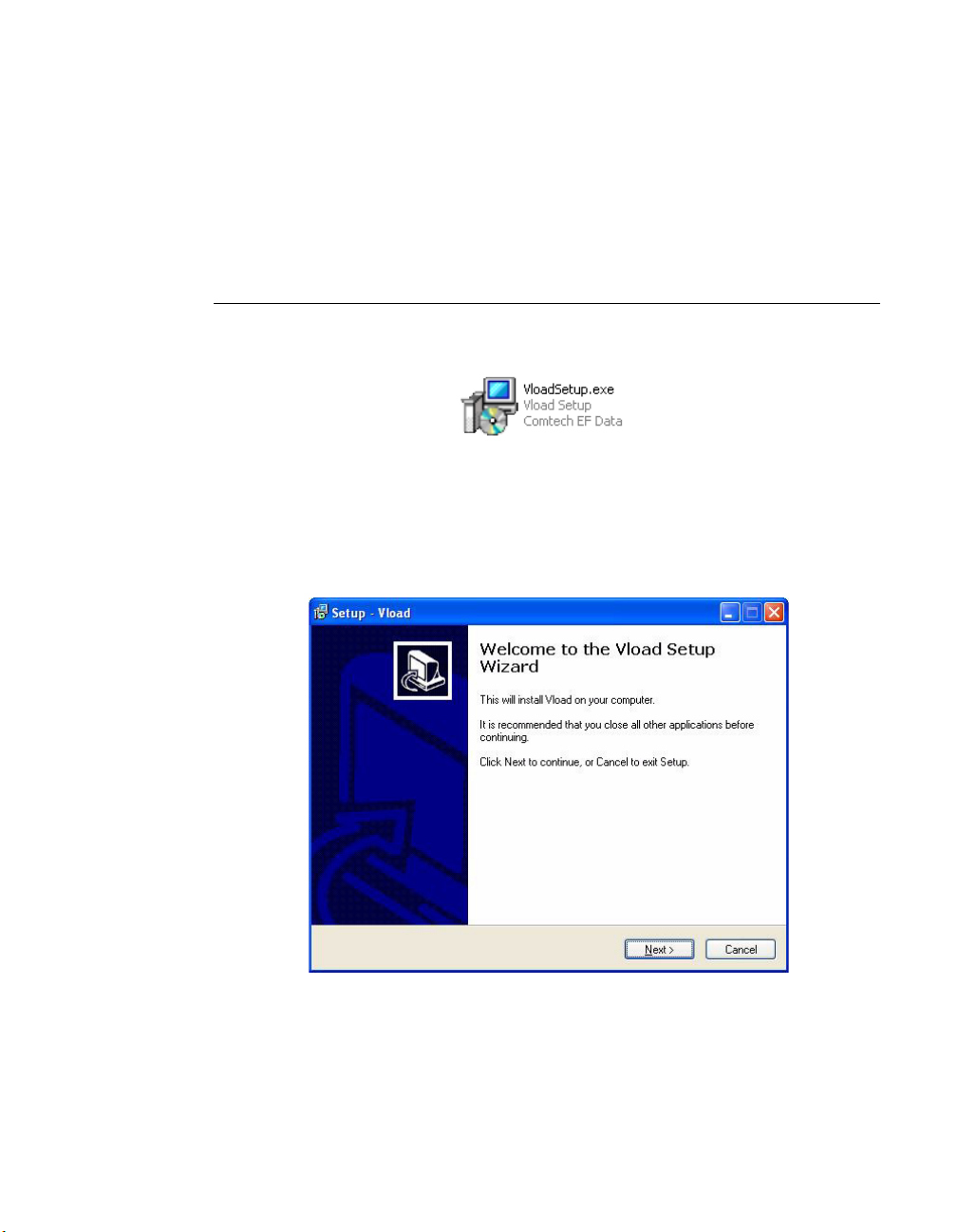
Copy the VLoad Installation file to the local C: drive of the workstation.
Figure 2-2
VLoad Installation File
Open the Comtech EF Data VLoad Setup Wizard by double-clicking on the
VLoadSetup icon. The initial window of VLoad Setup will appear, as shown in
figure 2-3, below.
Figure 2-3
VLoad Setup Wizard, Initial window
Click on the Next button to continue with program installation.
Chapter 2 - VLoad Installation 2-3
Page 20
Installing VLoad
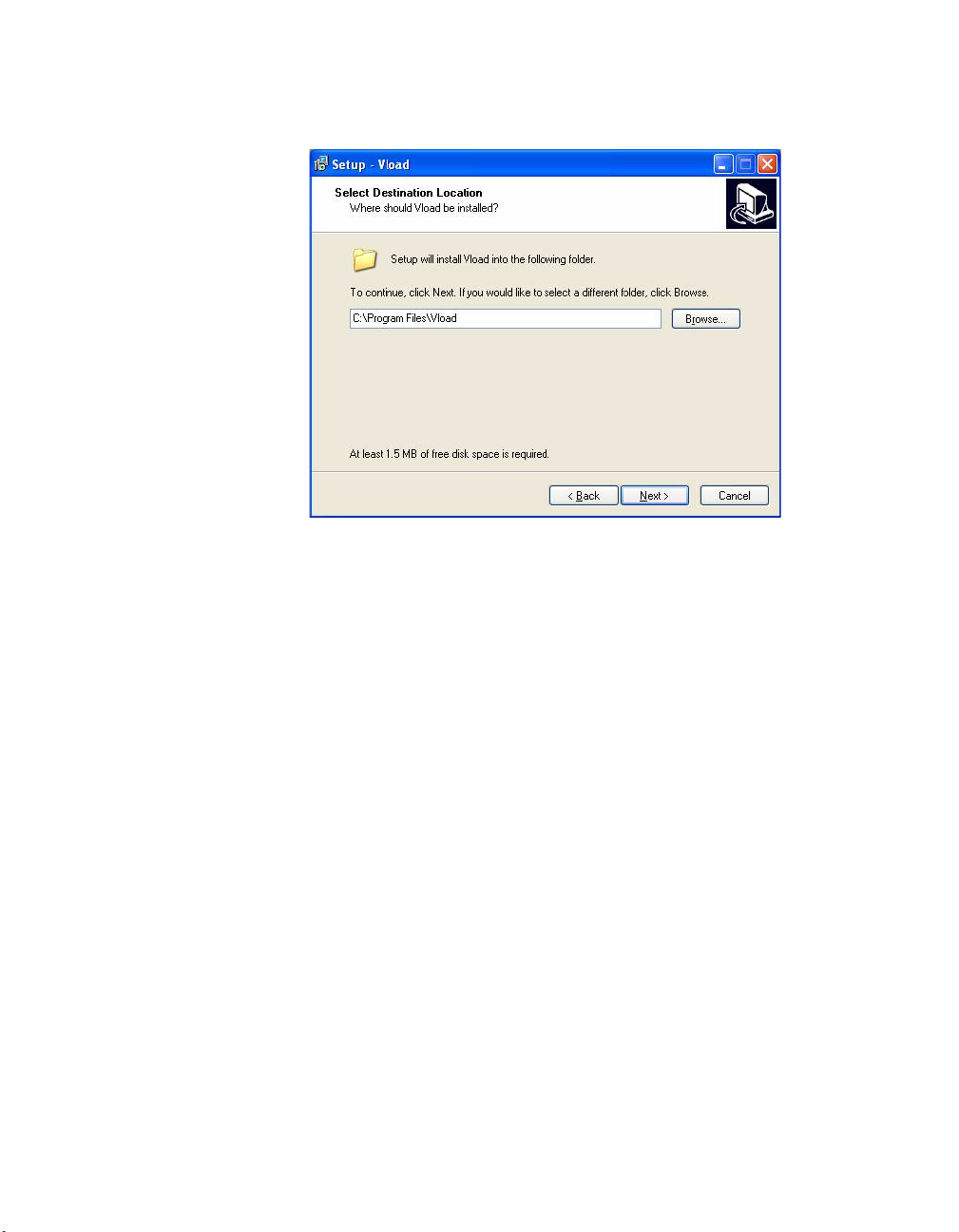
Destination Location
Figure 2-4
Select Destination Location, VLoad Setup
Select the destination for the VLoad files as they are installed. If the user does
not specify a destination, the installation program provides a default.
Click the Next button to proceed.
2-4 VLoad User Guide
Page 21
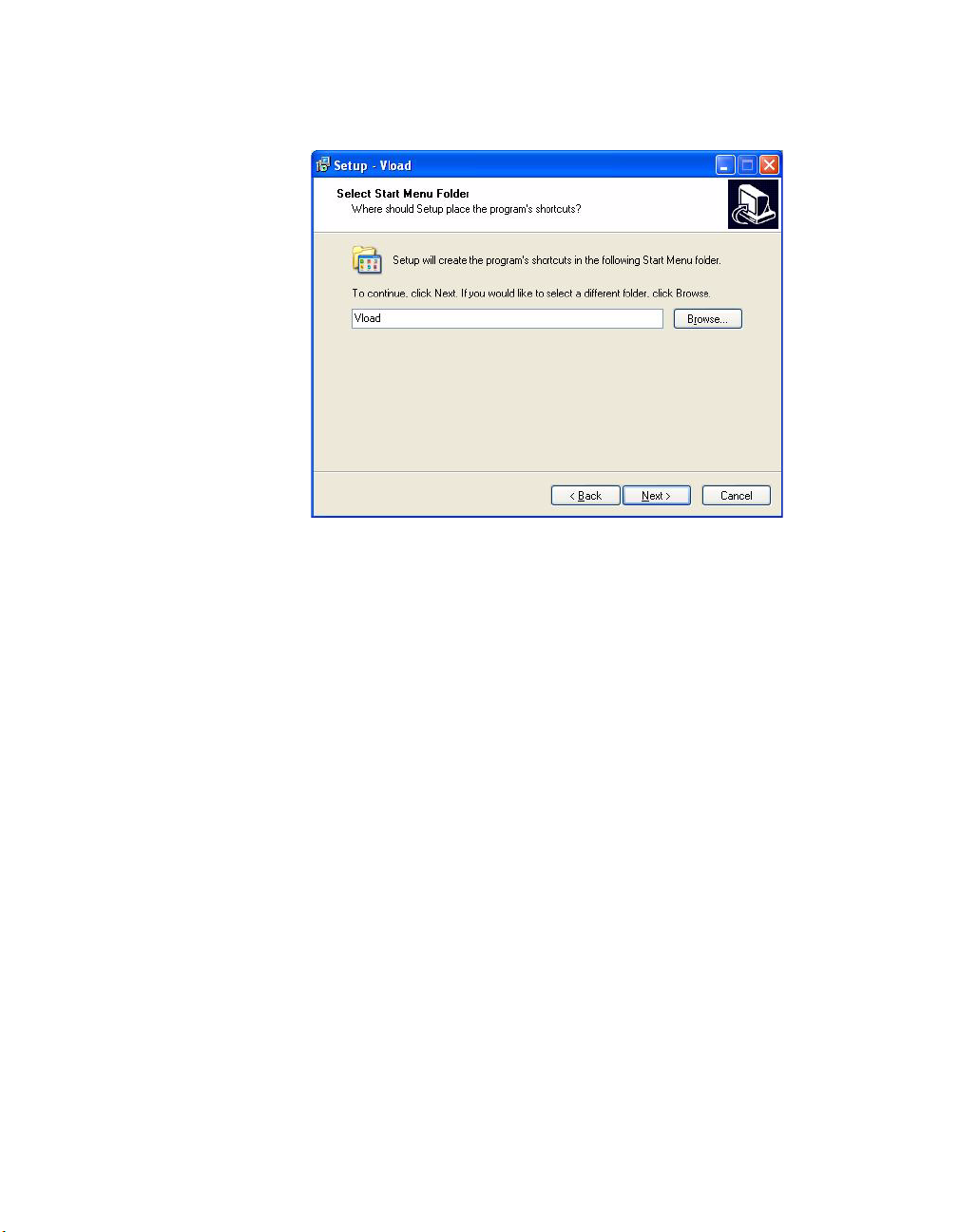
Select Start Menu Folder
Installing VLoad
Figure 2-5
Select Start Menu Folder, VLoad Setup
Select the name of the folder located in the Start Menu. If the user does not
specify a name, the installation program provides a default.
Click the Next button to proceed.
Chapter 2 - VLoad Installation 2-5
Page 22
Installing VLoad
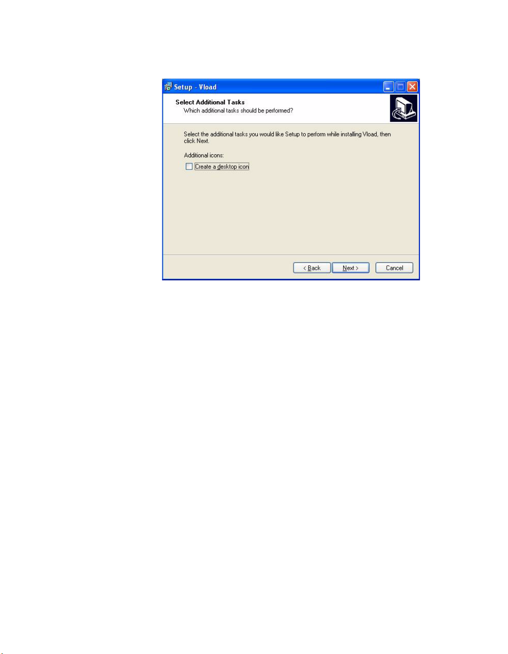
Create a Desktop Icon
Figure 2-6
Create Desktop Icon, VLoad Setup
Click the Create a desktop icon box to instruct the installation program to
automatically create a shortcut on your desktop, if desired.
Click the Next button to proceed.
2-6 VLoad User Guide
Page 23
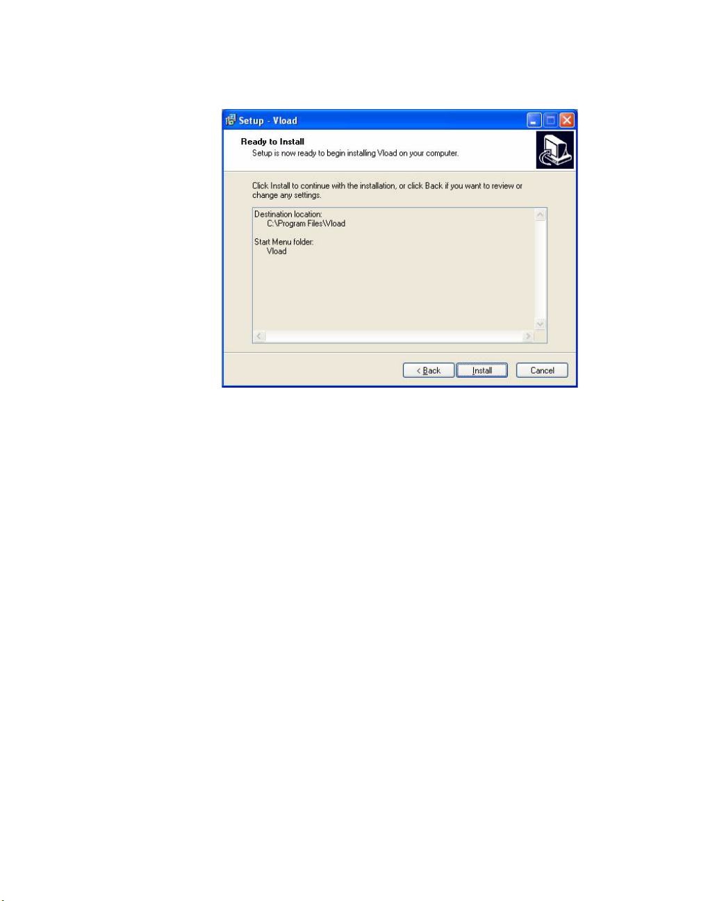
Ready to Install
Installing VLoad
Figure 2-7
Ready to Install dialog, VLoad Setup
The Ready to Install window provides a synopsis of the installation including
the destination for the installed files and the name of the Start Menu folder.
This window is the last opportunity for the user to terminate installation of the
program.
Ensure that all information presented in the synopsis is correct and click Install
to complete the installation.
Chapter 2 - VLoad Installation 2-7
Page 24
Installing VLoad
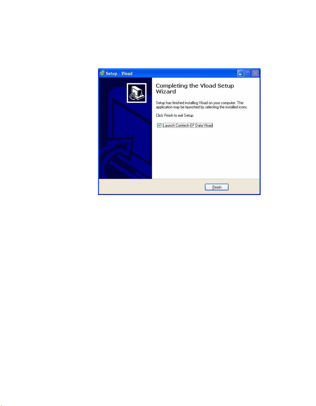
Completing Installation of VLoad
Upon a successful installation of the VLoad program, the Completing Setup
window will appear.
Figure 2-8
Completing Installation, VLoad Setup
Select the Launch Comtech EF Data VLoad box to launch VLoad after exit-
ing the installation setup program.
Click the Finish button to exit VLoad Setup.
2-8 VLoad User Guide
Page 25

C
NOTE
USING VLOAD — VIPERSAT MODE
This chapter covers using VLoad with a Vipersat network. For a Digicast
network, refer to Chapter 4, “Using VLoad — Digicast Mode”.
In Vipersat mode, VLoad only supports modem/routers with the Vipersat
feature enabled. Attempts to use VLoad with network units that are not Vipersat-enabled will result in a protocol error. For more information on enabling the
Vipersat feature, refer to the user documentation for that unit.
HAPTER
Note: Refer to the VLoad Release Notes for current information on what
features are supported for each modem type.
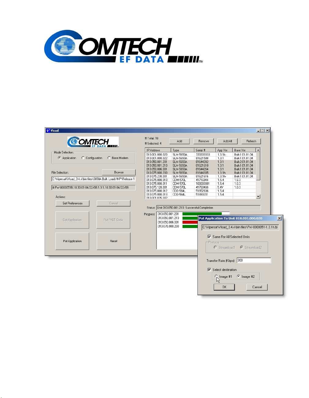
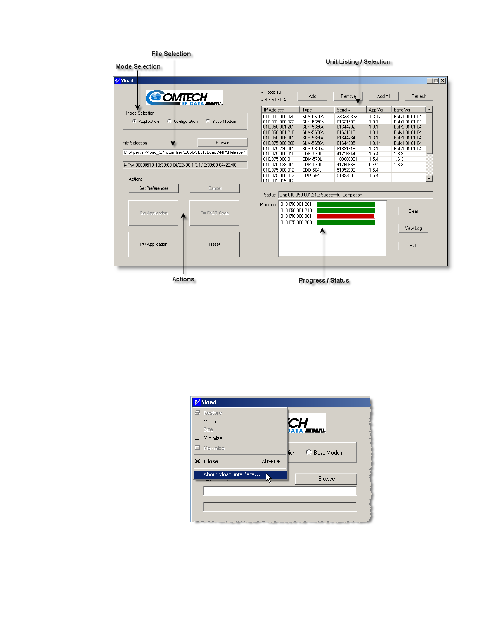
Main Window Description
This section describes how to use the controls and capabilities that are available
in VLoad. The five functional areas of the Main Window are shown in
figure 3-1, below.
Chapter 3 - Using VLoad — Vipersat Mode 3-1
Page 26
Main Window Description
Figure 3-1
VLoad Main Window, Functional Areas
About VLoad
Clicking on the V icon in the upper left corner of the main VLoad window title
bar will display a pull-down menu as shown in figure 3-2.
Figure 3-2
Click on About vload_interface... to open the About VLoad window, showing
the version number for this edition of VLoad.
VLoad Pull-Down Menu
3-2 VLoad User Guide
Page 27

Main Window Description
Figure 3-3
About VLoad window
Unit Listing / Selection Area
This area of the main window is used to add and remove units to/from the
modem list for purposes of retrieving (Get) and/or replacing (Put) either the
configuration file, the application image, or the base modem image for the
modem(s). Detailed information for each modem in the list is also available for
viewing. This information can be immediately updated with the use of the
Refresh button.
Following a Refresh operation, VLoad creates and saves a simple text file
named
Settings\<username>\Application Data\Vload
text editor, and because it is comma-delimited, can be imported into a spreadsheet for offline use.
More details on how to use this area of VLoad are provided in the “Unit Listing
and Selection” section on page 3-18.
VloadUnitList.txt in the Windows directory C:\Documents and
. This file can be opened with a
Mode Selection Area
The specific functions of VLoad that are available for action on the listed
modems vary depending on which Mode and Preference and what Type of unit
is selected at that time.
• Application – This mode is used to Get and/or Put an application image
(firmware) from/to the unit(s), as well as to Put a FAST Feature Code to
the unit. The “Application Mode” section on page 3-23 describes Putting
and Getting the binary (.bin) image file for a Vipersat modem.
• Configuration – This mode is used to Get and/or Put a configuration file
from/to the unit(s), as well as to edit the Param file for a unit. The
“Configuration Mode” section on page 3-32 describes Putting, Getting,
and editing the configuration file (.txt) for a Vipersat modem.
Chapter 3 - Using VLoad — Vipersat Mode 3-3
Page 28

Main Window Description
The Vipersat Parameter Editor User Guide contains detailed information
for using the Parameter Editor portion of VLoad to configure and optimize
the Vipersat modems in your satellite network.
• Base Modem – This mode is used to Put a base modem image (firmware)
to the unit(s) that are selected, as well as to select which image to run. The
“Base Modem Mode” section on page 3-39 describes selecting and
uploading a base modem image in binary format from a .bin file to one or
more modem units.
Use the appropriate radio button in the Mode Selection block, shown at the top
of the main window in figure 3-1, to select the mode of operation for VLoad.
File Selection Area
This area of the main window is used to either specify the file name and location
for a Get operation to be saved to, or to select the desired file for a Put operation. A Browse button is available for locating the desired directory and file, or
the desired path can be entered using the keyboard.
The file type used for both Application mode and Base Modem mode is binary
(.bin). The file type used for Configuration mode is either text (.txt) or Vipersat
(.vipersat-modem-config); the latter is a VMS-compatible file type. During a
Get operation, the utility prompts for a file name and choice of the desired
directory to save this file to; typically, this will be the same directory in which
the VLoad.exe program file resides.
File Type and Naming
Since there can be more than one type of .bin file (e.g., CDM-570L Application
file, CDD-564L Application file, Base Modem file), each type should be saved
using a different name so that they can be easily identified. It is recommended
that the .bin file names be based on the firmware release level for that file type.
This is the convention that is used with the original files that are provided by
Comtech EF Data.
For example, for a CDM-570/L modem, the Application file will have a
name such as
such as
Also, a unique file name can be assigned to the Configuration parameter file for
each unit for backup purposes.
VLoad has a smart feature that enables it to distinguish the various file types,
and will not allow the wrong file type to be selected for a particular action. For
example, VLoad will not allow the operator to select a router Application .bin
3-4 VLoad User Guide
FW10875N.bin, and the Base Modem file will have a name
FW10805Y.bin.
Page 29
Main Window Description
file when in the Base Modem mode. Similarly, in Application mode, a CDD564L .bin file can not be Put to a CDM-570L modem.
This smart feature can be overridden by changing the Preferences setting to
Unrestricted. See the “Unrestricted” section on page 3-7 for more about this
preference.
There are two boxes in the File Selection area. The upper box is used to specify
the path and filename. The lower box is read-only and displays additional information for the selected file, such as the file name or the modem type, and the
time and date of creation. This information text may extend beyond the visible
area of the box—use the right/left arrow keys to scroll through the text.
Actions Area
The buttons in the Actions area of the VLoad main window are used to select
the actions for VLoad to perform. Other than the top two buttons, Set Prefer-
ences and Cancel, the available actions and the button’s labels will change
depending on the Mode selected in the Mode Selection area, the Preference
selected in the Actions area, and the Type of modem unit that is selected in the
Unit Listing area. These dependent button functions will be described in the
three Mode Selection sections that follow.
The common Action button functions are described below.
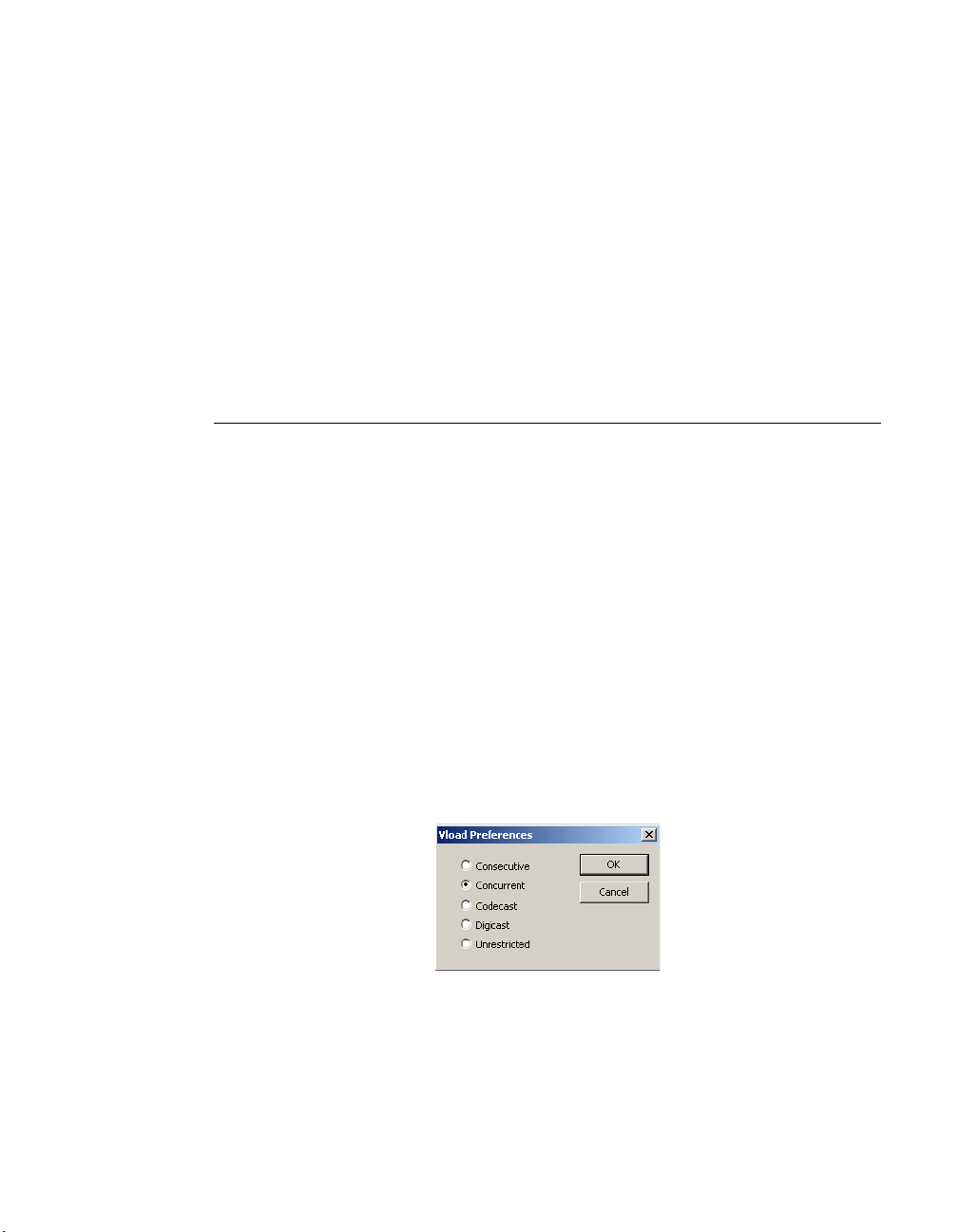
Set Preferences
Clicking the Set Preferences button displays the VLoad Preferences dialog
box shown in figure 3-4. Making selections in the radio buttons in this dialog
will determine the Put and Reset method to be used when loading the firmware,
configuration, or Fast Code to selected Vipersat modems.
Figure 3-4
Consecutive
Selecting the Consecutive radio button instructs the VLoad utility to Put/Reset
the data to the selected Vipersat modems sequentially. All selected Vipersat
Chapter 3 - Using VLoad — Vipersat Mode 3-5
VLoad Preferences dialog
Page 30

Main Window Description
NOTE
modems in the network will receive the data in sequence in the order they are
displayed in the unit listing / selection area shown in figure 3-1.
Concurrent
Selecting the Concurrent radio button instructs the VLoad utility to Put/Reset
the data to the selected Vipersat modems using n different unicast streams all at
the same time, each stream directed toward one unit. All Vipersat modems in
the network will receive the data at the same time.
Note that this option requires that there be sufficient bandwidth available on the
TDM outbound to handle multiple streams at the specified data transfer rate.
Codecast
Note: The Codecast preference selection only applies to a Put or Reset opera-
tion. A Get action does not use Codecast for the data transfer.
Codecast is not supported for the SLM-5650A.
Codecast uses a streaming multicast method to upgrade the modem firmware
and/or the Param file. When the Hub TDM outbound capacity is limited, Codecast is a useful option for transferring/resetting data.
Caution: Codecast should only be used with a full understanding of its
limitations, and only in situations where the potential benefit offsets
the risks.
Selecting the Codecast radio button causes the VLoad utility to transfer the data
to the targeted Vipersat modems without verifying the integrity of the data
transfer. Thus, the data will not be re-sent in the event that the target modem
receives a corrupted data block. However, the integrity of the file is checked by
the receiving modem prior to writing the data to flash, so the worst case is that
the file transfer will not have succeeded.
Codecast is received by all units configured to listen to the chosen multicast
address:
• If no units are selected in the Unit Listing area (
# Selected: 0), then all
units associated with the multicast address will accept the transfer/reset.
• If specific units are selected, the list of these units is transmitted along
with the file via multicast, and those targeted units that are not on the list
will ignore the transfer/reset.
Using the Codecast preference will result in some alteration of window appearances, such as with the Actions area of the main window and with some of the
dialogs.
3-6 VLoad User Guide
Page 31

Main Window Description
NOTE
NOTE
Digicast
Selecting the Digicast radio button instructs the VLoad utility to present the set
of windows and dialogs that are applicable for Digicast network products. For
more information on this setting, refer to Chapter 4, “Using VLoad — Digicast
Mode”.
Unrestricted
Selecting the Unrestricted radio button instructs the VLoad utility to Put the
data to the selected Vipersat modems without performing a validation check.
The validation check ensures that the source file is compatible with the modem
type. This preference allows VLoad to be used with new modem models that
have not yet been predefined in the utility. This preference only affects Put
operations.
Following the completion of the unrestricted Put operation(s), it is recommended that the preference be returned to a setting for common operations.
Note: Although this preference setting disables the file validation function in
VLoad, a similar file validation function within the modem will prevent an
incompatible image or configuration from being saved in that modem
unit. Should an incompatible file be Put to a modem, a Streamload error
will occur and the Put attempt will fail, as shown in figure 3-5.
Figure 3-5
Put Streamload Error
Cancel
The Cancel button only becomes enabled during a Get or Put operation, and is
used to cancel the transfer before it is completed. The rest of the time this button
is disabled (grayed out).
Note: The Cancel button cancels the communications between VLoad and the
targeted unit(s). This means that a data transfer operation that is in prog-
Chapter 3 - Using VLoad — Vipersat Mode 3-7
Page 32

Main Window Description
ress will stop. However, if a Put operation has reached either the image
flash burn phase or the router-to-base modem file transfer phase,
executing a Cancel will terminate the unit status update to VLoad but will
not end the current operation. This is indicated by the button label
changing from Cancel to Detach.
The exception to this is for Codecast operations, where the Cancel
command includes an abort command for the modem(s) to terminate the
Codecast session.
Reset
The Reset button is used for resetting a unit, typically after a Put operation, to
apply the new settings as specified in the dialog window that opens, as shown in
figure 3-6. When using the Codecast preference setting, this button is labeled
Codecast Hard Reset, and the dialog window appearance is as shown in
figure 3-7.
Figure 3-6
Figure 3-7
3-8 VLoad User Guide
Put Reset Request dialog
Codecast Reboot dialog
Page 33

Main Window Description
Caution: Never reset a unit (or units) during the image flash burn process of a
Put operation. This will result in an incomplete and unusable modem
image.
The Reset button is inactive (grayed out) during a transfer operation,
as a safety precaution. However, in the event that a Put operation is
canceled during an image flash burn, the Reset button will become
active.
Reset Type
• Hard Reset – this reset is equivalent to a power-off/power-on cycle and
reboots the unit.
Note that a Hard Reset is the only available reset type when using
Codecast.
• Soft Reset – this reset restarts all of the tasks in the application of the
modem (e.g., STDMA, Auto-Switching, etc.); subset to a Hard Reset.
• Go to Home State – this reset forces the modem unit to the Home State
configuration.
The modem image(s) that will be run following a Reset default to the current
modem settings which can be viewed in the Unit Information window (see
“Unit Information” section on page 3-18).
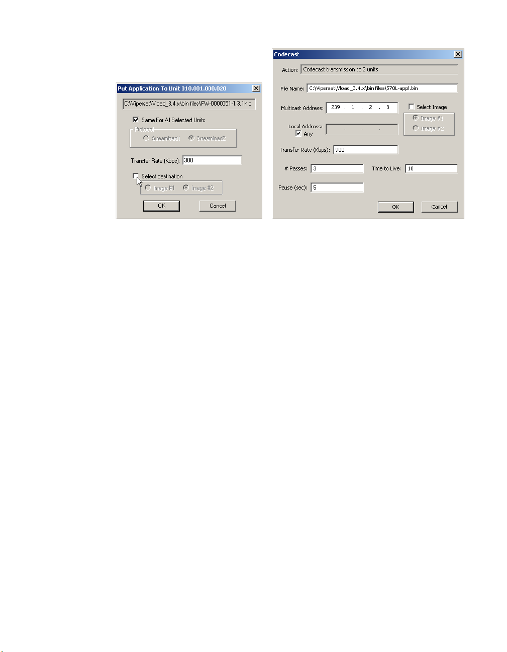
For Put Reset Request:
When Reset Type is Hard, Image selection is available. To change either the
Application Image to Run or the Base Modem Image to Run on the modem,
click on the Select check box to enable these settings.
If multiple units are selected for this action, the Same For All Selected
Units check box will appear, providing the option to perform this Put to the
group using the same specified settings.
The Protocol type will be automatically determined, unless the device type
is unknown; in this case, either Streamload1 or Streamload2 can be selected.
For Codecast Reboot:
Enter the Codecast Multicast Address of the unit(s) to be reset. This
parameter defaults to 239.1.2.4 since this is the Codecast Address of all
Vipersat units when they are shipped from the factory.
If desired, the IP address of the network interface card (NIC) on the local
host machine can be specified to be used for the multicast. This setting
defaults to Any.
To change the Image to run on the modem, click on the Select check box to
enable these settings.
Chapter 3 - Using VLoad — Vipersat Mode 3-9
Page 34

Main Window Description
Because Codecast utilizes multicast with no verification, the dialog displays
the following IP multicast parameter settings:
• # Passes – the number of transmissions to each unit (default is 3).
• Pause – the time, in seconds, between transmissions (default is 5 sec).
• Time to Live – the maximum number of router hops/seconds to reach a
unit before the data packet expires (default is 10). This parameter
prevents possible looping of the packet transmission in the network.
These settings are editable; however, the default values are typically
adequate for most networks.
The Send Codecast Termination setting enables the clearing of the
Codecast port flag set in the targeted modem(s) for a recent Put operation
that was not completed due to an event such as:
• An interruption caused by a crash/reboot of VLoad or the PC/
workstation.
• A Cancel attempt that was unsuccessful in aborting the session.
Status / Progress Area
The lower right area of the main VLoad window is known as the Status/Prog-
ress area, as shown in figure 3-1. This area provides status information for any
actions that are executed on the modem units. Text information appears in the
Status box, and real-time colored progress bar(s) are graphically displayed in
the Progress box below.
Progress Bar Color Code
The progress bar is color coded to indicate the type of Put/Get file transfer in
process. There are four colors associated with the progress bar and the colors
will have slightly different meanings, depending on the transfer type and the
success/failure of the transfer.
• Red – A red progress bar indicates an error has occurred during the Put
file transfer, resulting in a failure. A red outlined progress bar is displayed
when there is no response from the unit, or a connection failure occurred.
A solid red progress bar is displayed when the error occurred after a
connection was established. Refer to the event log file for details on the
specific error/failure type.
• Blue – A blue outlined progress bar is displayed when VLoad is
attempting to establish connection to the unit. A solid blue progress bar
3-10 VLoad User Guide
Page 35

Main Window Description
indicates that there is a file transfer in process. A solid blue progress bar is
also displayed upon completion of the Refresh process.
• Orange – An orange progress bar indicates that a flash memory burn is in
process. Note that this process is only displayed for units using
Streamload2 (e.g., SLM-5650A). A Get operation that is completed but is
not saved will also result in an orange progress bar to alert the user.
• Green – A green progress bar indicates that the file transfer or action was
successful.
• Yellow – A yellow progress bar indicates that a Codecast transfer is in
progress or has been made. Since a Codecast transfer has no error
detection or correction, there will never be an error condition shown with
this transfer type.
A sample Codecast Put operation is shown in figure 3-8. Note that the
progress bars are yellow and that three tries to the same IP address are
shown in progress. The sample Codecast is being made to a known bad IP
address, but there is no error detected or displayed by VLoad.
Yellow is also used for all Reset requests on modems running Application
firmware version 1.5.3.3 or earlier, which are always unverified. For all
SLM-5650A modems, as well as any other units running version 1.5.3.4 or
later, Reset status will be displayed with red or green progress bars.
Figure 3-8
Chapter 3 - Using VLoad — Vipersat Mode 3-11
Codecast Application (Put) in Progress
Page 36

Main Window Description
Caution: Note that some actions, such as the Put command, may require
several minutes to be performed. Once an action is initiated, do not
attempt a subsequent action until the progress status (both the text
information and the progress bar(s)) indicates that the first action is
either completed, failed, or is terminated with the Cancel button.
Set Defaults / Clear
The upper button in the Progress area of the main window is a dual function
button. When no progess status information is displayed, the button label
appearance is Set Defaults. Clicking this button resets most VLoad parameters
to their initial default settings, as listed below.
•
Unit List
• Column order: IP Address, Type, Serial #, App Ver, Base Ver
• Column widths: 100, 90, 90, 72, 90 pixels
• Row order: ascending IP address
For each unit
•
• Transfer rate: 900 Kbps
• Port number: c001 hex (hard-coded)
• Attempts: 3 iterations
• Timeout: 3 seconds
• Reset type: hard
• Application
• Next image to run: unchecked (current modem setting)
• Next image to save: unchecked (current modem setting)
• Next image to get: unchecked (current modem setting)
• Flash timeout: 90 seconds (hard-coded)
• Base Modem
• Next image to run: unchecked (current modem setting)
• Next image to save: unchecked (current modem setting)
• Flash timeout: 120 seconds (hard-coded)
• Configuration
• Get from: active
• Put to: active only
• Flash timeout: 30 seconds (hard-coded)
• Unit Information
• FAST code: none
• Device type: none
• Serial number: none
• Name: none
• Version: none
• Network ID: none
3-12 VLoad User Guide
Page 37

Main Window Description
NOTE
• Codecast parameters
• Time to live: 10 hops
• Local address: any
• Remote Multicast address: 239.1.2.4
• Repetition: 3 iterations
• Transfer rate: 900 Kbps
• Pause: 5 seconds
• Port number: c001 hex (hard-coded)
• Application
• Next image to run: unchecked (current modem setting)
• Next image to save: unchecked (current modem setting)
• Base Modem
• Next image to boot: unchecked (current modem setting)
• Next image to save: unchecked (current modem setting)
•
Window placement: centered
Note: To reset all VLoad parameters to their initial default settings, rename the
VLoad.exe file. This establishes a new set of values in the Windows
registry, including unit listing, file selection links, and window position on
the desktop.
When progress status information is displayed following a VLoad action, the
button label appearance is Clear. Click on the Clear button to clear the display
in the Progress area.
View Log
Clicking the View Log button opens the event log file, displaying the activity
taken by the VLoad Utility as shown in the example in figure 3-9.
Event log data provides a handy reference as to what action has been taken by
VLoad with any Vipersat modem in the network, and the corresponding results.
The information is contained in a simple text file named
creates in the Windows directory
Application Data\Vload
. This file can be opened independently of the VLoad
C:\Documents and Settings\<username>\
program, providing an easy means for copying or saving the file and/or its
contents in a variety of formats for offline use.
The event log contains a detailed history of sequenced events, and provides a
useful tool for troubleshooting problems.
Chapter 3 - Using VLoad — Vipersat Mode 3-13
Vload.log that VLoad
Page 38

Main Window Description
NOTE
Figure 3-9
View Log window
Note: Each time the VLoad application is opened, a new log file is created,
overwriting the previous log file. To retain a previous log file, either
rename it or relocate it to another directory prior to restarting VLoad.
Exit
Clicking on the Exit button terminates VLoad and closes the program.
3-14 VLoad User Guide
Page 39

Image Selection
NOTE
NOTE
The user should have a thorough understanding of the material presented in this
section prior to performing image selection operations as described in the Appli-
cation Mode (page 3-23) and Base Modem Mode (page 3-39) sections of this
user guide.
Image Selection
Warning: This is an advanced feature to be used only by depot level setup and
Note: In the following discussion, the following terms are synonymous: IP
repair technicians and users who have been trained in the use of this
procedure.
Using this feature requires a detailed understanding of the unit’s
architecture. Unless the user thoroughly understands this feature, its
use can result in an unusable unit.
Option, IP Bulk, and Application. The word “unit” refers to the combination of the Base Modem and IP Option. The word “image” refers to the
binary image of the software that controls the unit as well as its location
in flash memory.
Saving Images to Units
Amongst its features, VLoad can save an image (Base Modem and/or IP
Option) to flash memory and then reboot (Hard Reset) the system. This section
describes how VLoad can be used to control the placement of these images in
flash memory. Without VLoad, the image selection must be done via either the
menu based CLI (Command Line Interface) or the Web Browser Interface and
then the image downloaded via FTP. VLoad integrates these two functions. The
images are labeled “Image 1” and “Image 2” based on where they are physically
located in the unit’s memory space.
Note: The Vipersat CDM-570/570L and SLM-5650A have separate and inde-
pendent images for both the Base Modem and the Application (IP/Router
Option). Since the Base Modem and Application have different release
cycles, their images are not kept synchronized. In other words, the latest
Base Modem might be in Image 1 while the latest Application might be in
Image 2.
The image saving options are:
•Image 1
•Image 2
• Existing (Unchecked)
The system booting options are:
•Image 1
•Image 2
Chapter 3 - Using VLoad — Vipersat Mode 3-15
Page 40

Image Selection
• Existing (Unchecked)
The default setting for these options in VLoad is Existing/Unchecked (current
modem setting).
Image 1 and Image 2
Image 1 and Image 2 are self explanatory; the image is always saved to or
booted from the selected image, independent of its status.
Existing Image (Unchecked)
Existing refers to the current setting of the unit without regard to how it was last
set from the CLI, Web, or VLoad. For “Put Application” or “Put Base Modem”,
this means that VLoad will send the image to the unit and the unit will determine which image to use based on the currently existing setting. Similarly for
Hard Reset, VLoad will just send a reset command and the unit will use its
existing setting to do the reboot. In other words, selecting “Existing” is essentially a “No Operation” in terms of selecting the affected image.
Finally, setting the image for Hard Reset is always persistent through reboots,
but setting the image for Base Modem reboot or Put Application is only effective until the unit is rebooted unless the configuration is saved to flash before
rebooting.
For example, if VLoad does a “Put Application” to Image 1 and the modem was
configured to “Upgrade” to image 2, then the Application will be saved in
Image 1. However, if the unit is then Hard Reset without first saving the configuration, then if the next time VLoad does a “Put Application” to existing, the
application will be saved in Image 2.
Special Base Modem Considerations
When doing a hard reset, both the Base Modem and the IP Option are always
booted. The process is controlled by the IP option which sets the image for the
Base Modem and then issues a reset command to the Base Modem after which
the IP Option resets itself. This is the only option that affects the image selection for both the Base Modem and the Application. Selecting either Image 1 or
Image 2 for a Hard Reset will cause the appropriate Application to be booted
along with the last selected image of the Base Modem. Likewise, selecting Hard
Reset with the Existing image will cause the unit to determine which images to
reboot for both the Base Modem and Application.
3-16 VLoad User Guide
Page 41

Starting VLoad
Locate the VLoad.exe file in the VLoad directory on the hard drive of the workstation and double-click to open it. The initial VLoad window will appear, as
shown in figure 3-10.
Starting VLoad
Figure 3-10
Once the VLoad utility has been started, the next step is to list the unit(s) from
which information is to be retrieved, or that require action to be performed on
them. This is described in the next section, “Unit Listing and Selection”.
Chapter 3 - Using VLoad — Vipersat Mode 3-17
VLoad Utility, Initial Window
Page 42

Unit Listing and Selection
Unit Listing and Selection
The listing and selection area of the main window, shown in Figure 3-11, lists
the modem units which have been accessed by the VLoad utility. Typically, the
first time that VLoad is started, no units will be displayed. Units must be added
to the listing through the use of the Add and Add All buttons, which are
described below.
Figure 3-11
Unit Listing / Selection box, InfoTip displayed
Unit Information
The unit listing information that is displayed in the main VLoad window
includes the IP Address, the modem Type, the Serial number, and the Application and Base Modem versions associated with each unit.
Note that in figure 3-11 there is an information pop-up shown that displays
detailed information for the unit under the pointer. This information is only
displayed momentarily (by Windows Explorer) when the mouse pointer rolls
over the IP Address for a unit.
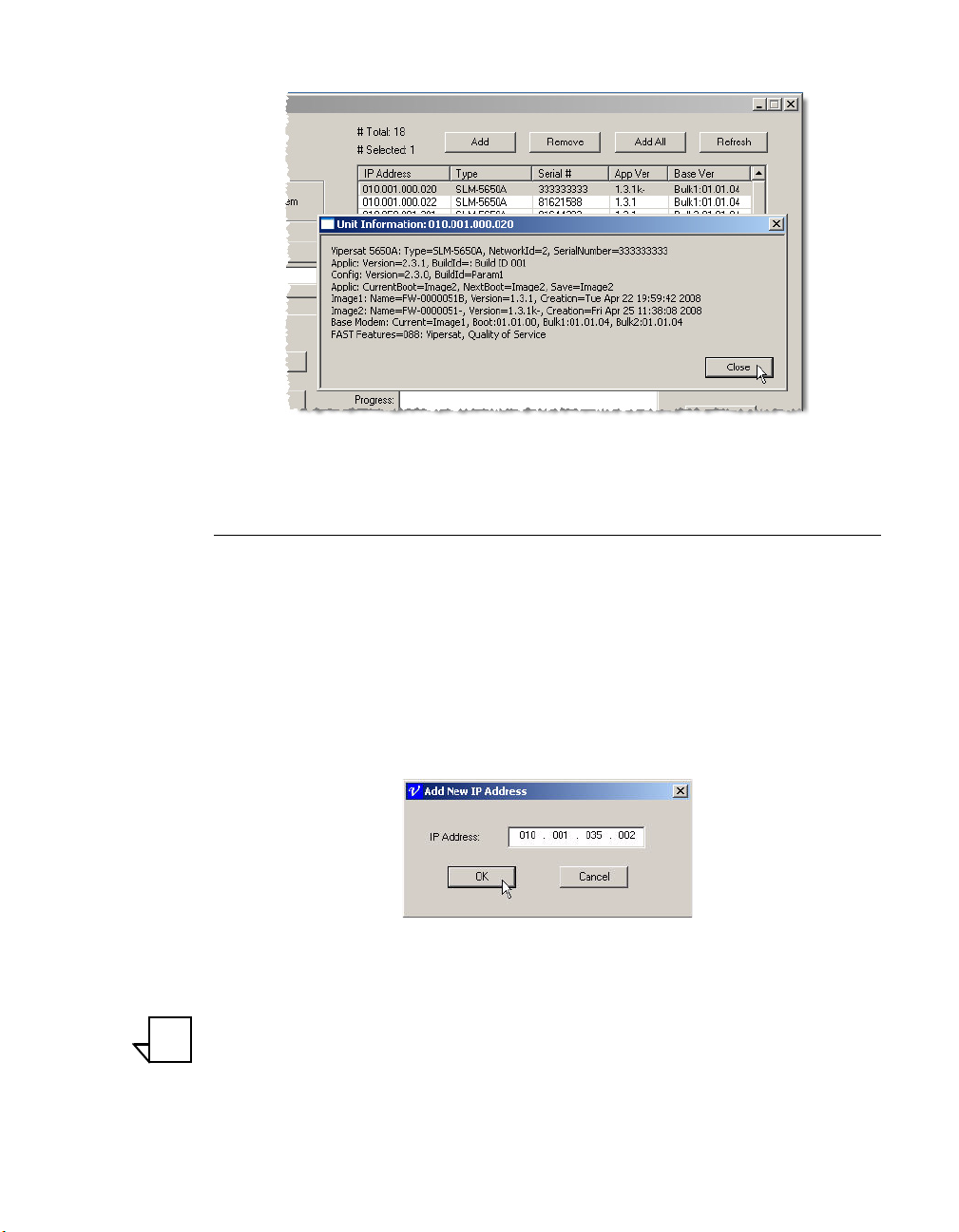
This same detailed information can be displayed by double-clicking on a unit
listing to open the Unit Information window for that modem, as shown in
figure 3-12.
Click the Close button to close the window.
Tip: Following a Refresh or Add All operation, the unit information can also be
viewed in the VLoad event log, as shown in figure 3-9.
3-18 VLoad User Guide
Page 43
Unit Listing and Selection
NOTE
Figure 3-12
Unit Information window
Adding Units
A unit is added to the list by either:
• Clicking the Add button, or
• Clicking the Add All button
Add
Clicking the Add button allows adding a single Vipersat modem using the
dialog shown in Figure 3-13.
Figure 3-13
Add New IP Address dialog
Note: The SLM-5650A has three IP addresses: the Base Modem address, the
Chapter 3 - Using VLoad — Vipersat Mode 3-19
TRANSEC (transmission security) address, and the Router/NP (network
processor) option card address. Only use the IP address of the NP card
with VLoad.
Page 44

Unit Listing and Selection
Enter the IP address of the unit, then click the OK button to add that unit to the
list. The IP address of the unit will appear in the list with all other fields blank,
as shown in figure 3-14. There is no unit verification nor auto retrieval of unit
information with the Add function.
Figure 3-14
New IP Address Added
Whenever a unit is added using the Add button, VLoad only displays its IP
address and leaves all the rest of the fields blank. To fill in the rest of the data,
click the Refresh button to retrieve the data from any target unit(s) that are live
on the network.
Add All
Clicking the Add All button allows adding multiple units to the list by specifying one or more Multicast Addresses for the Vipersat network, as shown in
figure 3-15.
Figure 3-15
Add All dialog
3-20 VLoad User Guide
Page 45

Unit Listing and Selection
This dialog window allows multicast addresses to be added, removed, and
edited. Enter the Receive Multicast Address that is assigned to the units that are
to be listed. By default, the address 239.004.005.006 always appears in the
address listing, since this is the default Receive Multicast Address of all Vipersat units when they are shipped from the factory.
As is typical with multicast configurations, the attempts, timing, and addressing
can be specified, as is required for the given network.
• Attempts – Enter the number of attempts for sending the multicast until
receiving a reply from the units. When multiple multicast addresses are
specified, this number of attempts will apply for each address before
proceeding to the next address.
• Timeout – Enter the number of seconds to wait for responses to the
multicast poll before going on to the next attempt.
• Time to Live – Enter the number of router hops/seconds allowed between
the point of origin and the destination before the data packet expires. For
example, a setting of 5 would prevent remote mesh unit responses from
getting back to a host at the Hub. This parameter prevents possible looping
of the packet transmission in the network.
• Local Address – Specify the address of the network interface card (NIC)
on the local host machine to be used for the multicast. If necessary, the
specific IP address can be entered; otherwise, the Any box should be
checked. This parameter is provided to accomodate host machines that
have multiple NICs.
Removing Units
Units can be removed from the listing area with the use of the Remove button.
Select the unit(s) to be removed, then click on the Remove button. A dialog
window will appear that requires the operation to be confirmed or cancelled.
Refresh
The unit information for listed modems can be updated by clicking the Refresh
button at the top of the Listing/Selection area of the main window. This Refresh
operation is performed on a selective basis. To update the information for a
single unit, first select the unit to highlight its listing, then click Refresh. Multiple units can be selected and updated in a similar manner. If no units are
selected, clicking the Refresh button will result in all listed units being updated.
Chapter 3 - Using VLoad — Vipersat Mode 3-21
Page 46

Unit Listing and Selection
Each listed unit is polled consecutively. The status of the polling and retrieval of
information is displayed in the Progress area of the window, as shown in
figure 3-16. Three attempts, each with a two second time-out, are made to
retrieve the current status of the unit. If a VLoad Refresh action is unable to
retrieve information from a target unit, that event (Fail) is displayed in the
Status box, indicating that the IP address is either invalid or is not accessible on
the network. Refer to the event log for more detailed information, such as which
unit(s) failed the refresh attempt.
Figure 3-16
Progress Status, Unit Refresh
Order of the List
The order of the unit listing can be modified in several ways. Clicking on a
column heading will toggle the list between ascending and descending order for
that column. Subsequently clicking on another column heading will sub-order
the list based on the first heading.
The five columns can also be re-arranged by click-hold and dragging a column
heading to the right or to the left. Column widths are adjusted using standard
table methods.
Once the desired modem units have been listed, the next step is to select the unit
or units to be acted upon and choose the appropriate action for VLoad to
perform. These actions are described in the following sections for Application
Mode, Configuration Mode, and Base Modem Mode.
3-22 VLoad User Guide
Page 47

Application Mode
NOTE
Selecting the Application radio button in the Mode Selection box, shown in
figure 3-17, sets VLoad to act on the application firmware running on the router
portion of the selected Vipersat modems.
Application Mode
Figure 3-17
Application Mode Selection
This mode is used to Get and/or Put an application image from/to the unit(s), as
well as to Put a FAST Feature Code to the unit.
Note: Button captions displayed and functions available for all modes are
controlled by the Mode selected from the Mode Selection radio buttons,
the selected Preference, as well as the Type of modem unit that is
selected from the Unit List.
File Selection
When performing a Put action, the Application .bin file must first be selected.
By default, VLoad will automatically select the previous Application .bin file
that was last Put to—or retrieved from (Get)—a modem. Use the Browse button
to locate another file, or a file that is stored in another directory, as shown in
figure 3-18. Alternatively, the path for the desired file can be entered directly
using the keyboard.
Chapter 3 - Using VLoad — Vipersat Mode 3-23
Page 48

Application Mode
Figure 3-18
Application File Selection
To acquire a current release image for updating the Application (IP) portion of a
modem, the image file can be downloaded from the Comtech EF Data website,
as shown in figure 3-19.
Figure 3-19
Acquiring Application Image from Website
Once the flash upgrade file has been downloaded, use the File Selection
Browse button to locate and select the image file to be uploaded to the target
modem(s).
Actions
When the Application radio button in the Mode Selection box is chosen and a
device (or devices) in the Unit Listing area is selected, the buttons in the
Actions area are activated with the following labels:
3-24 VLoad User Guide
Page 49

Application Mode
NOTE
• Get Application – This action retrieves a copy of the router application
image from the modem and saves it, either for back-up purposes or to Put
it to another modem. The Get Application button is activated if a single
unit is selected, and deactivated (grayed out) when multiple units are
selected.
• Put Application – This action replaces the router application image in the
designated Save To slot for the modem with the chosen .bin file. When
using the Codecast preference, this action button is labeled either
Codecast Application (when units are selected) or Codecast Application
to ALL Units (when no units
are selected).
This button is activated if the file displayed in the File Selection frame is a
valid application file, confirmed by the display of the Vipersat modem’s
model and the file’s creation time and date in the lower read-only display
in the File Selection area.
If a valid file is not currently selected, this button will be grayed out.
Either browse to locate a valid file, or first perform a Get Application
operation on a modem unit that has the appropriate file.
Note: For new modem types that have not yet been predefined in VLoad, file
validation can be inhibited by setting the Preferences to Unrestricted.
Using this preference in Application Mode will allow any application file
to be Put to any modem type. See the “Unrestricted” section on page 3-7
for more information.
• Put FAST Code – This action allows the operator to add a new FAST
(Fully Accessible System Topology) Code to the selected unit(s). The Put
FAST Code button is always enabled unless no unit selection has been
made.
Get Application
Clicking the Get Application button displays the Get Application From Unit
dialog window shown in figure 3-20.
Figure 3-20
Get Application dialog
Chapter 3 - Using VLoad — Vipersat Mode 3-25
Page 50

Application Mode
The Get Application function is only operable for one unit at a time, so only one
modem can be selected from the unit list.
In the default window shown in figure 3-20, only the Transfer Rate (Kbps)
dialog box is editable. Select a transfer rate between 1 and 9980 Kbps which
will transfer data error-free, or use the default value of 900 Kbps.
Clicking the Select Which Image to Get check box enables the selection of the
Image file to retrieve, as shown in figure 3-21. If this box is not checked, then
the Image will default to Existing and be determined from the current modem
setting.
Figure 3-21
Get Application dialog, Advanced
In the Image box, use the radio buttons to select which image from the target
unit is to be retrieved. The options are:
• Image #1 – The first image stored in the unit’s flash memory.
• Image #2 – The second image stored in the unit’s flash memory.
Refer to the “Image Selection” section on page 3-15 for detailed information on
these different image types and how they are used in the modem.
Tip: A Vipersat modem’s active and flash memories do not necessarily contain
the same version of the unit’s operating software. Make certain that the
source (active or flash memory) of the Get command contains the desired
version to be downloaded by the VLoad utility. To determine which version
is contained in each image, open the Unit Information window for that
unit (refer to the “Unit Information” section on page 3-18).
Clicking the OK button sets the values to be used and initiates the Get action.
The Progress area of the main window will display the transfer progress status
shown in figure 3-22. The Blue progress bar indicates that a transfer is in
process.
3-26 VLoad User Guide
Page 51

Application Mode
NOTE
Figure 3-22
Get Application Progress Status
When the transfer is successful, VLoad invokes a Save As file dialog, allowing
a name and path to be chosen for storing the .bin file. If saved, the appearance of
the progress bar will change to Green to indicate that the operation was successful. If the file is not saved, the progress bar will change to Orange and the staus
text will state that the operation was completed, but the file was not saved.
Figure 3-23
Get Completed, File Not Saved
Put Application / Codecast Application
Clicking the Put Application / Codecast Application button displays the
dialog window shown in figure 3-24.
Note: The files put by the Put Application command are only put to the
modem’s Vipersat router board. Refer to the “Base Modem Mode”
section on page 3-39 for putting files to the base modem portion of the
modem.
This function is operable for either a single unit or multiple units. If multiple
units are selected for a Put Application, the Same For All Selected Units check
box will appear, providing the option to perform the Put to the group using the
same specified settings.
Chapter 3 - Using VLoad — Vipersat Mode 3-27
Page 52
Application Mode
Figure 3-24
Put Application / Codecast Application dialog
For a Put Application, the File box at the top of the window is read-only and
shows the path and file name (designated in the File Selection box in the main
window) of the binary file to be Put to the target Vipersat modem.
For a Codecast Application, the file path and name can be edited, if desired.
The Multicast Address specified determines the modem group to be targeted.
By default, the address 239.1.2.4 appears since this is the default Codecast
Multicast Address of Vipersat units when they are shipped from the factory.
Because Codecast utilizes multicast with no verification, the Codecast Application dialog displays the following IP multicast parameter settings:
• # Passes – the number of transmissions to each unit (default is 3).
• Pause – the time, in seconds, between transmissions (default is 5 sec).
• Time to Live – the maximum number of router hops/seconds to reach a
unit before the data packet expires (default is 10). This parameter prevents
possible looping of the packet transmission in the network.
• Local Address – the address of the network interface card (NIC) on the
local host machine to be used for the multicast. If necessary, the specific
IP address can be entered; otherwise, the Any box should be checked. This
parameter is provided to accomodate host machines that have multiple
NICs.
These settings are editable; however, the default values are typically adequate
for most networks.
Select a Transfer Rate between 1 and 9980 Kbps which will transfer data
error-free, or use the default value of 900 Kbps.
3-28 VLoad User Guide
Page 53

Application Mode
NOTE
Clicking the Select Destination/Image check box enables the selection of the
Image to which the file will be copied, as shown in figure 3-25.
Note: The Select Destination option is not available for SLM-5650A modems;
for these units, the new image is always Put to the inactive image.
Figure 3-25
Put Application dialog, Image Selection
If this box is not checked, then the Image will default to Existing and be determined from the current modem setting. Note that the Unit Information window
can be opened to view the firmware version for each of the images, as well as
the Current, Boot, and Save Image designations.
The Put options available in the Image box of the Put dialog allow the Save To
image slot of the modem to be designated for replacement of the application .bin
file:
• Image #1 – The application file will be written to the target unit’s slot with
the label of Image #1.
• Image #2 – The application file will be written to the target unit’s slot with
the label of Image #2.
The Put operation transfers the selected application file to the designated Save
To image slot by writing it to the target unit’s flash memory. This is non-volatile memory used by the modem’s Vipersat IP router board to persistently store
its application programs. These stored images are not currently running on the
unit, but can be selected from flash memory by command as required. Refer to
the “Image Selection” section on page 3-15 for additional information.
Clicking the OK button sets the values to be used and initiates the Put action.
The Progress area of the main window will display the transfer progress status.
The Put Application is a two-step process:
1) The file is transferred to the unit.
2) The data is written to flash memory.
Chapter 3 - Using VLoad — Vipersat Mode 3-29
Page 54

Application Mode
This process can take up to several minutes, depending on the data transfer rate
as well as the type and the number of units selected. For example, the Put Application process to a single SLM-5650A modem at a transfer rate of 1,000 Kbps
will take approximately 2.5 minutes to transfer the file and another 6 minutes to
write the data to flash.
Following a successful Put operation, executing a Hard Reset will command
the modem to reboot and load the new image.
Put FAST Code
Clicking the Put FAST Code button displays the Put FAST Code To Unit
dialog window shown in figure 3-26. This function allows a feature enhancement upgrade for the selected modem unit(s) to be implemented through the use
of a unique access code that is purchased from Comtech EF Data.
Figure 3-26
Put FAST Code dialog
The Put FAST Code function is operable for either a single unit or multiple
units. If multiple units are selected, the Same For All Selected Units check box
will appear, providing the option to upgrade the group with this same feature.
Note, however, that since each unit requires a unique code, Putting to multiple
units will result in the appearance of a FAST Code prompt dialog for each unit.
Enter the 20-character hexidecimal access code in the FAST Feature Code
box.
Click on the OK button to Put the FAST Code to the unit(s). The Progress area
of the main window will display the transfer progress status.
Following a successful Put operation, executing a Hard Reset will command
the modem to reboot and load the new feature codes.
All Application Mode actions are recorded in the event log. Clicking the View
Log button opens the log file, as shown in figure 3-27.
3-30 VLoad User Guide
Page 55

Application Mode
Figure 3-27
Event Log display for Get and Put Application
Chapter 3 - Using VLoad — Vipersat Mode 3-31
Page 56

Configuration Mode
NOTE
Configuration Mode
Selecting the Configuration radio button in the Mode Selection box, as shown
in figure 3-28, sets VLoad to act on the configuration parameter file that is
loaded into the selected Vipersat modems.
Figure 3-28
Configuration Mode Selection
This mode is used to Get and/or Put a configuration file from/to the unit(s), as
well as to Edit the parameter file for a unit.
Note: Button captions displayed and functions available for all modes are
controlled by the Mode selected from the Mode Selection radio buttons,
the selected Preference, as well as the Type of modem unit that is
selected from the Unit List.
File Selection
When performing a Put action, the Configuration file must first be selected.
This file can be one of two types:
• Text Configuration File – This file type is the standard .txt parameter file
type used by the Parameter Editor, the software utility that is used for
making configuration changes (see the “Edit Param File” section on
page 3-38).
3-32 VLoad User Guide
Page 57

Configuration Mode
• Vipersat File – This file type (.vipersat-modem-config) is VMS
compatible and is used when importing/exporting configuration files to/
from the VMS. This allows a configuration that has been exported from
the VMS to be selected and Put to a modem using VLoad.
Note that, when a Vipersat File is selected for a Put operation, VLoad
automatically creates a Text Confuguration File version of that same
configuration and places it in the original file’s directory. This is done to
enable configuration changes with the VLoad Edit Param File button
without having to first perform a Get operation and save the data as a .txt
file.
By default, VLoad will automatically select the previous Configuration file that
was last Put to–or retrieved from (Get)–a modem. Use the Browse button to
locate another file, as shown in figure 3-29. Alternatively, the file path may be
entered directly in the File Selection field.
Figure 3-29
Configuration Parameter File Selection
Actions
When the Configuration radio button in the Mode Selection box is chosen and a
device (or devices) in the Unit Listing area is selected, the buttons in the
Actions area are activated with the following labels:
• Get Configuration – This action retrieves a copy of the configuration
parameter file from the modem and saves it, either for back-up purposes or
to Put it to another modem. The Get Application button is activated if a
single unit is selected, and deactivated (grayed out) when multiple units
are selected.
• Put Configuration – This action replaces the existing configuration
parameter file for the modem with the chosen file. When using the
Codecast preference, this action button is labeled either Codecast
Configuration (when units are selected) or Codecast Configuration to
ALL Units (when no units
This button is activated if the file displayed in the File Selection frame is a
valid configuration file, confirmed by the display of the Vipersat modem’s
model and the file’s creation time and date in the lower read-only display
in the File Selection area.
are selected).
Chapter 3 - Using VLoad — Vipersat Mode 3-33
Page 58

Configuration Mode
NOTE
If a valid file is not currently selected, this button will be grayed out.
Either browse to locate a valid file, or first perform a Get Configuration
operation on a modem unit that has the appropriate file.
Note: For new modem types that have not yet been predefined in VLoad, file
validation can be inhibited by setting the Preferences to Unrestricted
Using this preference in Configuration Mode will allow any param file to
be Put to any modem type. See the “Unrestricted” section on page 3-7
for more information.
.
• Edit Param File – This action opens the Parameter Editor window for
making configuration changes to the param file that can then be Put to a
modem. The Edit Param File button is enabled whenever the File
Selection is valid and a ParamEdit.dll file for that version of parameter file
exists in the VLoad directory; no unit selection is required since this
function operates on a file that is in the network directory.
Get Configuration
Clicking the Get Configuration button displays the Get Configuration From
Unit dialog window shown in figure 3-30.
Figure 3-30
Get Configuration dialog
The Get Configuration function is only operable for one unit at a time, so only
one modem can be selected from the unit list.
Specify a Transfer Rate (Kbps) between 1 and 9980 Kbps which will transfer
the data error-free, or use the default value of 900 Kbps.
Select either Active or Flash as the From radio button, depending on whether
the configuration will be retrieved from the Active memory or the Flash
memory of the unit.
Clicking the OK button sets the values to be used and initiates the Get action.
The Progress area of the main window will display the transfer progress status
3-34 VLoad User Guide
Page 59

Configuration Mode
shown in figure 3-31. The Blue progress bar indicates that a transfer is in
process.
Figure 3-31
Get Configuration Progress Status
When the transfer is successful, VLoad invokes a Save As file dialog, allowing
a name, file type, and path to be chosen for storing the configuration file to the
designated directory. The file name, if not specified, defaults to the last previously named file. The file type defaults to a Text Configuration File (.txt) type,
but a Vipersat File (.vipersat-modem-config) type can be chosen from the pulldown menu, as shown in figure 3-32.
Figure 3-32
Save As dialog, Configuration File
Note that, when the Vipersat File type is chosen, a Text Configuration File is
also created automatically.
Chapter 3 - Using VLoad — Vipersat Mode 3-35
Page 60

Configuration Mode
If saved, the appearance of the progress bar will change to Green to indicate that
the operation was successful, as shown in figure 3-33, below. If the file is not
saved, the progress bar will change to Orange and the Status text will state that
the operation was completed, but the file was not saved.
Figure 3-33
Successful Get Configuration Status
Put Configuration / Codecast Configuration
Clicking the Put Configuration / Codecast Configuration button displays the
dialog window shown in figure 3-34.
Figure 3-34
Put Configuration / Codecast Configuration dialog
This function is operable for either a single unit or multiple units. If multiple
units are selected for a Put Configuration, the Same For All Selected Units
check box will appear, providing the option to perform the Put to the group
using the same specified settings.
3-36 VLoad User Guide
Page 61

Configuration Mode
NOTE
NOTE
Note: When Putting a configuration to multiple units, all of the selected units
will receive the same IP Address setting that is specified in the config
file. This will result in the loss of communications with all but one of these
units. Therefore, this method is only practicable, for example, when
initially configuring units at a service depot prior to deploying them in an
actual network.
The option to save the new configuration parameter file to the unit’s flash
memory can be chosen by clicking the Save in Flash check box. This option is
not available for Codecast.
For the SLM-5650A modem, the option to make this new configuration active
can be chosen by clicking the Activate check box. This is selectable for the
SLM-5650A only; for the CDM-570/570L modem, the new configuration is
always made active, and this option will appear grayed out.
Note: When Save in Flash is chosen, it is recommended that a new configura-
tion Put to a modem always be made active. This allows any performance problems caused by the new configuration to be discovered
sooner rather than later (i.e., a future modem reset).
For a Put Configuration, the File box at the top of the window is read-only and
shows the path and file name (designated in the File Selection box of the main
window) of the parameter file to be Put to the target modem.
For a Codecast Configuration, the file path and name can be edited, if desired.
The Multicast Address specified determines the modem group to be targeted.
By default, the address 239.1.2.4 appears since this is the default Codecast
Multicast Address of Vipersat units when they are shipped from the factory.
Because Codecast utilizes multicast with no verification, the Codecast Configuration dialog displays the following IP multicast parameter settings. These
settings are editable; however, the default values are typically adequate for most
networks.
• # Passes – the number of transmissions to each unit (default is 3).
• Pause – the time, in seconds, between transmissions (default is 5 sec).
• Time to Live – the maximum number of router hops/seconds to reach a
unit before the data packet expires (default is 10). This parameter prevents
possible looping of the packet transmission in the network.
• Local Address – the address of the network interface card (NIC) on the
local host machine to be used for the multicast. If necessary, the specific
IP address can be entered; otherwise, the Any box should be checked. This
parameter is provided to accomodate host machines that have multiple
NICs.
For CDM-570/L and CDD-56X units that are inactive (e.g., redundancy
standby) and currently have unknown/uncertain base modem configuration
Chapter 3 - Using VLoad — Vipersat Mode 3-37
Page 62

Configuration Mode
settings, select the Write Base Modem Parameters option. This will push the
parameter set of the selected file from the NP card to the base modem. This
option is not available for the SLM-5650A and will appear grayed out.
Select a Transfer Rate between 1 and 9980 Kbps which will transfer data
error-free, or use the default value of 900 Kbps.
Click on the OK button to Put the configuration to the unit(s). The Progress area
of the main window will display the transfer progress status.
Following a successful Put operation, the new parameter set can be activated
immediately by performing a Firm or Hard Reset (the Activate check box must
be selected, as shown in figure 3-34).
Edit Param File
Clicking the Edit Param File button opens the Parameter Editor window, as
shown in figure 3-35. A configuration file must be selected first by use of the
File Selection/Browse feature. The file can be either a Text Configuration File
type (.txt) or a Vipersat File type (.vipersat-modem-configuration).
Figure 3-35
Parameter Editor window
The Parameter Editor is used for making configuration changes to the param file
prior to performing a Put operation to the selected modem(s). Refer to the
Vipersat Parameter Editor User Guide for detailed information on this function.
Any changes made to the param file will invoke a Save As file dialog, allowing
a name, file type, and path to be chosen for storing the new file.
All Configuration Mode actions are recorded in the event log.
3-38 VLoad User Guide
Page 63

Base Modem Mode
NOTE
Selecting the Base Modem radio button in the Mode Selection box, shown in
figure 3-36, sets VLoad to act on the base modem firmware running on the unit.
Base Modem Mode
Figure 3-36
Base Modem Mode Selection
This mode is used to Put and/or Select the base modem image to/for the unit(s).
Note that the Get capability is not available in this mode.
Note: Button captions displayed and functions available for all modes are
controlled by the Mode selected from the Mode Selection radio buttons,
the selected Preference, as well as the Type of modem unit that is
selected from the Unit List.
File Selection
When performing a Put action, the base modem .bin file must first be selected.
By default, VLoad will automatically select the previous base modem .bin file
that was last Put to a modem. Use the File Selection Browse button to locate
another file, or a file that is stored in another directory. Alternatively, the path
for the desired file can be entered directly using the keyboard.
Chapter 3 - Using VLoad — Vipersat Mode 3-39
Page 64

Base Modem Mode
Figure 3-37
File Selection Browse Button
To aquire a current release image for updating the base modem portion of a
modem, the image file can be downloaded from the Comtech EF Data website,
as shown in figure 3-38.
Figure 3-38
Acquiring Base Modem Image from Website
Once the flash upgrade file has been downloaded, use the File Selection
Browse button to locate and select the image file to be uploaded to the target
modem(s).
Actions
When the Base Modem radio button in the Mode Selection box is chosen and a
device (or devices) in the Unit Listing area is selected, the buttons in the
Actions area are activated with the following labels:
3-40 VLoad User Guide
Page 65

Base Modem Mode
NOTE
NOTE
• Put Base Modem Image – This action replaces the base modem image in
the designated Save To slot for the modem with the chosen .bin file. When
using the Codecast preference, this action button is labeled either
Codecast Base Modem Image (when units are selected) or Codecast
Base Modem Image to ALL Units (when no units
are selected).
This button is activated if the file displayed in the File Selection frame is a
valid image file, confirmed by the display of the Vipersat modem’s model
and the file’s creation time and date in the lower read-only display in the
File Selection area. If a valid file is not currently selected, this button will
be grayed out. Browse to locate the appropriate file.
Note: For new modem types that have not yet been predefined in VLoad, file
validation can be inhibited by setting the Preferences to Unrestricted.
Using this preference in Base Modem Mode will allow any base modem
.bin file to be Put to any modem type. See the “Unrestricted” section on
page 3-7 for more information.
• Select Base Modem Image – This action designates from which base
modem image the unit will boot and run. When using the Codecast
preference, this action button is labeled Codecast Select Base Modem
Image.
Put Base Modem Image / Codecast Base Modem Image
Clicking the Put Base Modem Image / Codecast Base Modem Image button
displays the dialog window shown in figure 3-39.
Figure 3-39
Note: The files put by the Put Base Modem Image command are only put to the
Chapter 3 - Using VLoad — Vipersat Mode 3-41
unit’s base modem board. Refer to the “Application Mode” section on
Put Base Modem Image / Codecast Base Modem Image dialog
Page 66

Base Modem Mode
NOTE
This function is operable for either a single unit or multiple units. If multiple
units are selected for a Put Base Modem Image, the Same For All Selected
Units check box will appear, providing the option to perform the Put to the
group using the same specified settings.
For a Put Base Modem Image, the File box at the top of the window is read-only
and shows the path and file name (designated in the File Selection box of the
main window) of the binary file to be Put to the target Vipersat modem.
For a Codecast Base Modem Image, the file path and name can be edited, if
desired.
The Multicast Address specified determines the modem group to be targeted.
By default, the address 239.1.2.4 appears since this is the default Codecast
Multicast Address of Vipersat units when they are shipped from the factory.
Because Codecast utilizes multicast with no verification, the Codecast Base
Modem Image dialog displays the following IP multicast parameter settings:
page 3-23 for putting files to the Vipersat router board portion of the
modem.
• # Passes – the number of transmissions to each unit (default is 3).
• Pause – the time, in seconds, between transmissions (default is 5 sec).
• Time to Live – the maximum number of router hops/seconds to reach a
unit before the data packet expires (default is 10). This parameter prevents
possible looping of the packet transmission in the network.
• Local Address – the address of the network interface card (NIC) on the
local host machine to be used for the multicast. If necessary, the specific
IP address can be entered; otherwise, the Any box should be checked. This
parameter is provided to accomodate host machines that have multiple
NICs.
These settings are editable; however, the default values are typically adequate
for most networks.
Select a Transfer Rate between 1 and 9980 Kbps which will transfer data
error-free, or use the default value of 900 Kbps.
Clicking the Select Destination/Image check box enables the selection of the
Image to which the file will be copied.
Note: The Select Destination option is not available for SLM-5650A modems;
for these units, the new image is always Put to the inactive image.
If this box is not checked, then the Image will default to existing and be determined from the Current modem setting. Note that the Unit Information window
can be opened to view the firmware version for each of the images, as well as
the Current, Boot, and Save Image designations.
3-42 VLoad User Guide
Page 67

Base Modem Mode
The Put options available in the Image box of the Put dialog allow the Save To
image slot of the modem to be designated for replacement of the application .bin
file:
• Image #1 – The image file will be written to the target unit’s slot with the
label of Image #1.
• Image #2 – The image file will be written to the target unit’s slot with the
label of Image #2.
The Put operation transfers the selected image file to the designated Save To
image slot by writing it to the target unit’s flash memory. This is non-volatile
memory used by the modem’s Base Modem board to persistently store its firmware. These stored images are not currently running on the unit, but can be
selected from flash memory by command as required. Refer to the “Image
Selection” section on page 3-15 for additional information.
Clicking the OK button sets the values to be used and initiates the Put action.
The Progress area of the main window will display the transfer progress status.
The Put Base Modem Image is a three-step process:
1) The file is transferred from the workstation to the unit’s router card RAM.
2) The router then transfers the file to the Base Modem.
3) The data is written to flash memory on the Base Modem board.
Note that this complete process may require up to several minutes, depending
on the data transfer rate as well as the type and the number of units selected.
Following a successful Put operation, executing a Hard Reset will command
the modem to reboot and load the new image.
Select Base Modem Image / Codecast Select Base Modem Image
Clicking the Select Base Modem Image / Codecast Select Base Modem
Image button displays the dialog window shown in figure 3-40, allowing the
selection of what image to run in the target modem on the next Reset.
This function is operable for either a single unit or multiple units. If multiple
units are selected for a Select Base Modem Image, the Same For All Selected
Units check box will appear, providing the option to perform this action on the
group using the same specified settings.
For a Codecast Select Base Modem Image, the Multicast Address specified
determines the modem group to be targeted. By default, the address 239.1.2.4
appears since this is the default Codecast Multicast Address of Vipersat units
when they are shipped from the factory.
Chapter 3 - Using VLoad — Vipersat Mode 3-43
Page 68

Base Modem Mode
Figure 3-40
Select Base Modem Image / Codecast Select Base Modem Image dialog
Because Codecast utilizes multicast with no verification, the Codecast Select
Base Modem Image dialog displays the following IP multicast parameter
settings:
• # Passes – the number of transmissions to each unit (default is 3).
• Pause – the time, in seconds, between transmissions (default is 5 sec).
• Time to Live – the maximum number of router hops/seconds to reach a
unit before the data packet expires (default is 10). This parameter prevents
possible looping of the packet transmission in the network.
• Local Address – the address of the network interface card (NIC) on the
local host machine to be used for the multicast. If necessary, the specific
IP address can be entered; otherwise, the Any box should be checked. This
parameter is provided to accomodate host machines that have multiple
NICs.
These settings are editable; however, the default values are typically adequate
for most networks.
The default Base Modem Image To Run can be designated by clicking on the
desired Image radio button:
• Image #1 – The base modem will run from the image in the target unit’s
slot with the label of Image #1.
• Image #2 – The base modem will run from the image in the target unit’s
slot with the label of Image #2.
Note that the Unit Information window can be opened to view the firmware
version for each of the images.
Refer to the “Image Selection” section on page 3-15 for additional information.
3-44 VLoad User Guide
Page 69

Base Modem Mode
Clicking the OK button performs the image selection action. The Progress area
of the main window will display the transfer progress status.
Perform a Refresh on the unit and verify the new image selection.
All Base Modem Mode actions are recorded in the event log.
Chapter 3 - Using VLoad — Vipersat Mode 3-45
Page 70

Base Modem Mode
{ This Page is Intentionally Blank }
3-46 VLoad User Guide
Page 71

C
NOTE
USING VLOAD — DIGICAST MODE
This chapter describes the controls and capabilities that are available in VLoad
when used with a Digicast network. For Vipersat networks, refer to Chapter 3,
“Using VLoad — Vipersat Mode”.
Starting VLoad
HAPTER
Locate the VLoad.exe file in the VLoad directory on the hard drive of the workstation and double-click to open it. When opening VLoad for the first time
following installation, the initial VLoad window will appear, as shown in
figure 4-1.
Note: Once the Preference is set to Digicast, subsequent openings of VLoad
Chapter 4 - Using VLoad — Digicast Mode 4-1
will display the Digicast main window, and it will not be necessary to
select the Digicast mode again.
Page 72
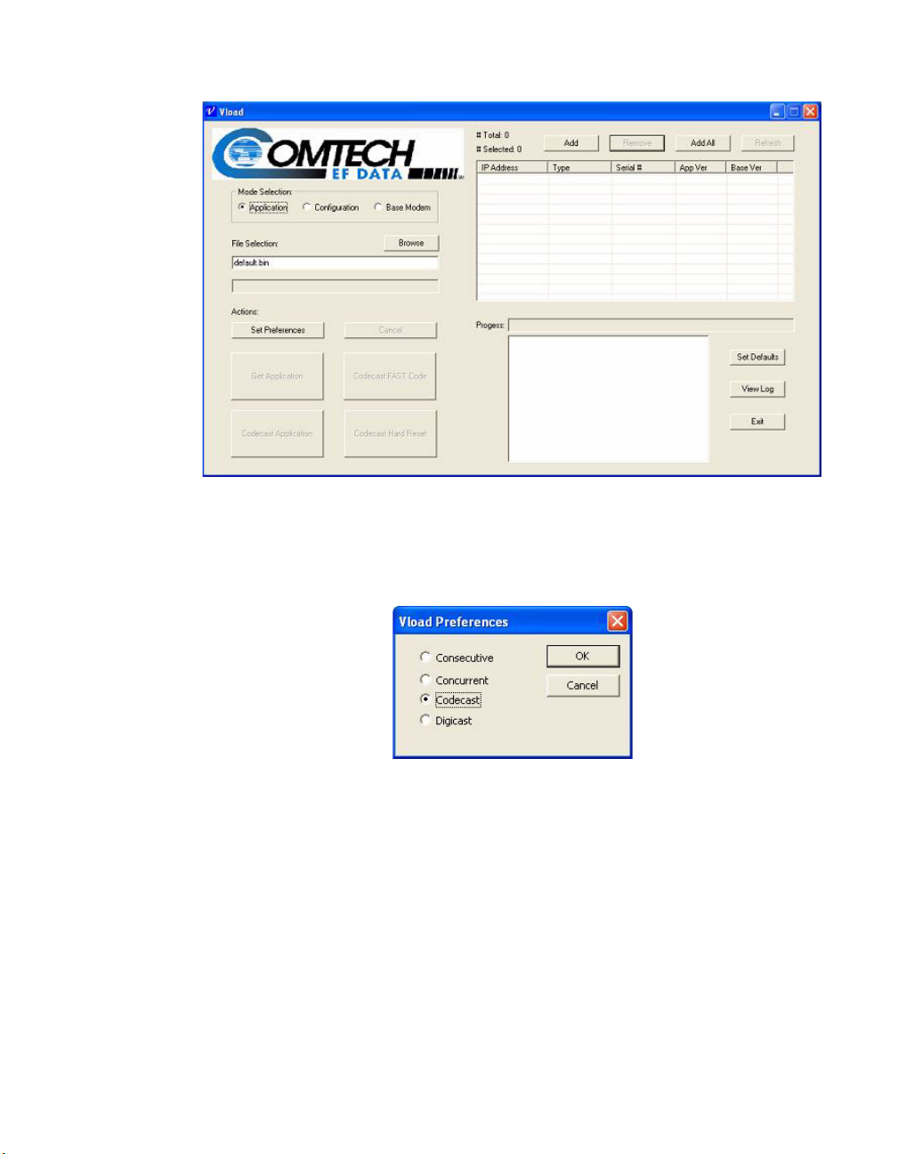
Starting VLoad
Figure 4-1
VLoad Utility, Initial Window
Select the Set Preferences button to open the VLoad Preferences dialog.
Figure 4-2
VLoad Preferences dialog
At this window, select Digicast and then click the OK button.
The Digicast Media Router Remote Commander main window will appear,
as described in the following section.
4-2 VLoad User Guide
Page 73

Digicast Media Router Remote Commander
NOTE
Digicast Media Router Remote Commander
Figure 4-3
VLoad Main Window, Digicast Mode
The Digicast Media Router Remote Commander window allows the user to:
maintain Digicast receivers, offer command functions that act upon the receivers, and navigate the program itself.
Note: In order to individually address a Digicast receiver on a network, the
receiver must be listed by its MAC address within the application.
Chapter 4 - Using VLoad — Digicast Mode 4-3
Page 74

Digicast Media Router Remote Commander
Digicast Receivers Area on the Remote Commander
Figure 4-4
Digicast Receivers Listing / Selection box
Add
Opens a dialogue that allows the user to add a receiver to the list below shown
in 3.1.1. This is required for individual addressing of remote commands.
Delete
Removes the selected receiver from the list.
Select All
Selects or unselects all receivers on the list.
Update All
Forces all receivers listening on the configured multicast address and PID to
respond to a remote command.
Receiver Listing
Receivers are identified by their MAC address. Other information can be
entered to assist in identifying the receiver.
Checkbox
Receivers are selected with a single left-click on the checkbox to the left of the
MAC address of the receiver.
4-4 VLoad User Guide
Page 75

Digicast Media Router Remote Commander
Adding a Receiver into Inventory
Figure 4-5
Digicast Add Device dialog
To successfully add a receiver to the Receiver Section, the user must specify the
MAC address. Additional information may be entered to allow easier recognition of the receiver.
• Name (Optional) – Any identifying attribute that is customer defined.
• MAC Address (Required) – The MAC address of each individual
receiver. The command package identifies the receiver through this
information.
• Model (Optional) – The Digicast model of the receiver.
• IP Address (Optional) – The IP address assigned to the Digicast device.
This is for customer information only.
Chapter 4 - Using VLoad — Digicast Mode 4-5
Page 76
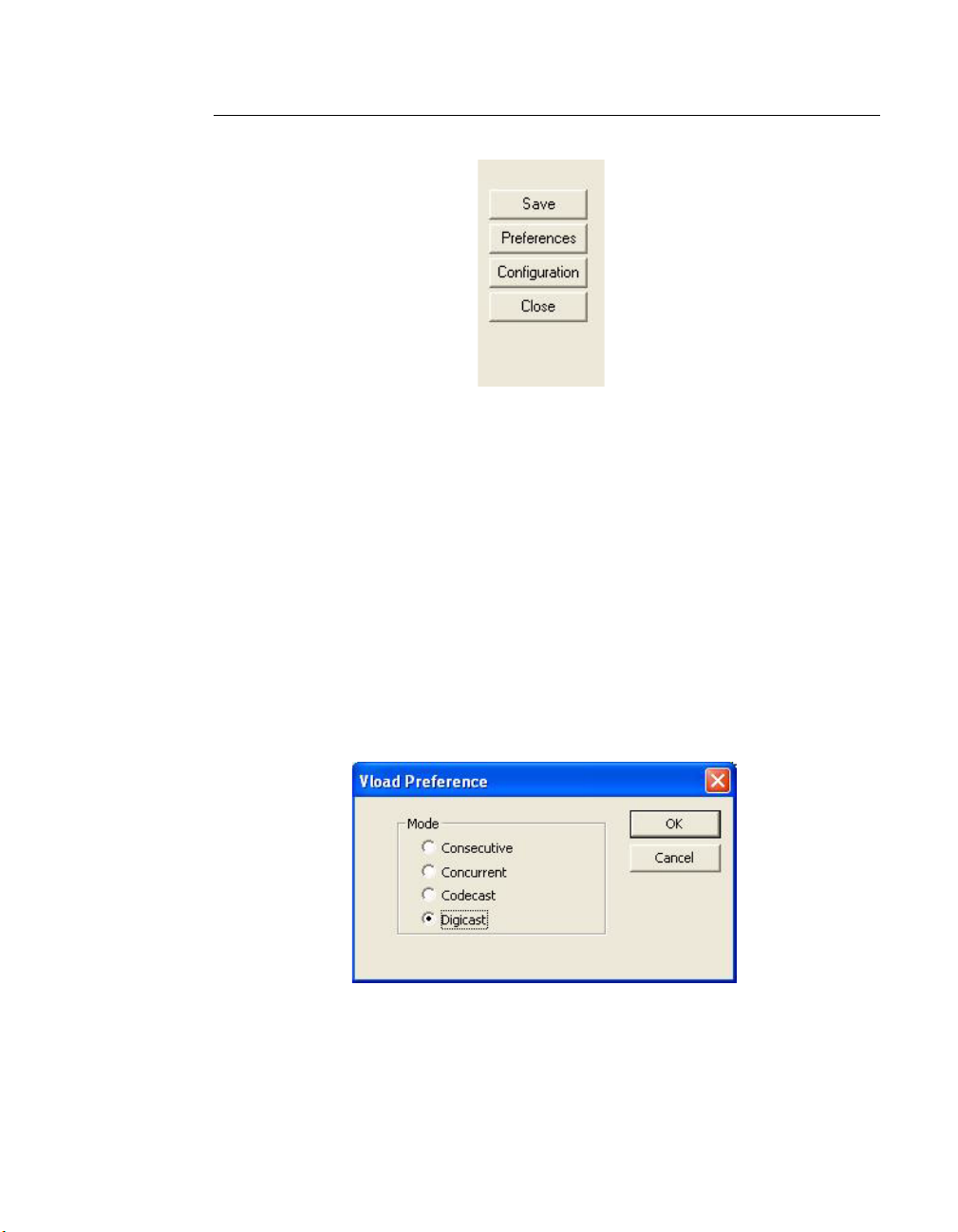
Digicast Media Router Remote Commander
Option Buttons Area on the Remote Commander
Figure 4-6
Digicast Option Buttons
• Save – Saves the changes made for adding or deleting receivers from the
Digicast device inventory listing.
• Preferences – Option to switch between the Vipersat VLoad interface and
the Digicast Remote Commander.
• Configuration – Brings up the Transfer Settings Configuration dialogue.
• Close – Closes the application.
Preferences Dialog
Figure 4-7
4-6 VLoad User Guide
VLoad Preference dialog
Page 77

Digicast Media Router Remote Commander
The preference dialog is used to switch between the Vipersat VLoad functions,
Consecutive, Concurrent, and Codecast, and the Digicast Media Router Remote
Commander.
Configuration Dialog
Figure 4-8
Digicast Transfer Settings dialog
The Configuration dialog is used to set the transmission parameters for the
commands to be sent out to the Digicast receivers.
• Multicast IP Address – The multicast address to transmit out on. This
address must be the same on the encapsulator and each Digicast receiver.
• Local IP Address – The IP address of the NIC on the computer to route
the commands.
• # Passes – The number of times to send out the command, with each
command being separated by the time specified in the Pause value. The
number of passes is valid with each command except for the Reset (or
reboot) command, which only sends the command once.
• Pause – The number of seconds to delay before transmitting the redundant
command(s). This setting works in conjunction with the # Passes setting.
• Time to Live – The limit on a period of time that the transmission of a unit
of data can experience before it should be discarded.
Chapter 4 - Using VLoad — Digicast Mode 4-7
Page 78

Digicast Media Router Remote Commander
• Port Number – The port number on the receiving unit.
• Transfer Rate – The actual rate(in Kilobits per second) to transmit the
outbound commands and associated data.
• Management PID – This is the PID that is used by the Digicast devices to
receive the remote command. Each Digicast receiver and encapsulator
requires that the same PID be used for management. The selection of
which PID to use is at the discretion of the user. The PID needs to be
consistent on all devices.
Transfer Status Area on the Remote Commander
The Transfer Status area is a visual display of the progress of the transfer
command. Configuring the settings is explained in detail in the Configuration
Dialog section.
Figure 4-9
Figure 4-10
4-8 VLoad User Guide
Transfer Status, In Progress
Transfer Status, Complete
Page 79

Digicast Media Router Remote Commander
Actions Area on the Remote Commander
Figure 4-11
• Reset – Reboots the receivers that are selected in the receiver listing.
• Tuner – updates either the Primary or Secondary Tuner settings on the
selected receivers.
• Firmware – Updates either the Application or FPGA code on the selected
receivers.
• PID – Creates, updates or deletes the PID settings on the selected
receivers.
The list of affected receivers can be selective by checking the individual receivers in the receiver list or by selecting Update all units, which sends out a global
broadcast.
Digicast Actions box
Reset
The Reset dialog differentiates from the other commands in that it does not
allow multiple passes for the reset command. The reset command is sent out
only once per command transfer attempt.
Chapter 4 - Using VLoad — Digicast Mode 4-9
Page 80

Digicast Media Router Remote Commander
Figure 4-12
Digicast Reset dialog
• Display of the Current Transfer Settings – displays the current transfer
settings, which can be altered in the configuration dialog.
• Display of Selected Receivers – includes the number of selected receivers
to receive the update and their respective information.
4-10 VLoad User Guide
Page 81

Tuner Setting Update
Digicast Media Router Remote Commander
Figure 4-13
Digicast Tuner Setting Update dialog
• Tuner Settings – Configurable settings on a Digicast receiver.
• Digicast Transfer Settings – Settings used for the transfer.
• Tuner Selection – Allows the user to select either the Primary or
Secondary when configuring the tuner settings and to implement the
modified settings.
• Selected Receivers – A listing of selected receivers, the MAC address and
the associated name of each unit selected to receive the Tuner Setting
update.
Chapter 4 - Using VLoad — Digicast Mode 4-11
Page 82

Digicast Media Router Remote Commander
Tuner Settings
Figure 4-14
Tuner Settings box
• LNB Frequency (MHz) – The frequency of the Local Oscillator that
resides in the Low Noise Block amplifier, located at the antenna. Review
the products specification sheet or visit the manufacturer’s web site for
information regarding the capabilities of the Low Noise Block in use.
• Down Frequency (MHz) – The receive frequency being down linked
from the satellite to the Low Noise Block amplifier.
The combination of the LO and the downlink frequency produces the LBand frequency expected by the DVB-S2 Media Receiver. To obtain the
L-band frequency, subtract the receive frequency from the LO frequency.
Some examples are shown below:
Example 1
LO = 10,750 MHz
Ku-Band Receive Frequency = 11,895 MHz
L-Band Frequency = 11,895 MHz – 10,750 MHz = 1,145 MHz
Example 2
LO = 10,600 MHz
Ku-Band Receive Frequency = 12,010 MHz
L-Band Frequency = 12,010 MHz – 10,600 MHz = 1,410 MHz
Example 3
LO = 5,150 MHz
C-Band Receive Frequency = 3,920 MHz
L-Band Frequency = 5,150 MHz – 3,920 MHz = 1,230 MHz
4-12 VLoad User Guide
Page 83

Digicast Media Router Remote Commander
• Symbol Rate (kbps) – The symbol rate will depend on the configured
mode of operation. The following combinations support the following
symbol rates.
Digital Video
Phase Shift Key Msps
Broadcast
DVB-S QPSK 2 – 45 Msps
DVB-S2 QPSK 6 – 32 Msps
DVB-S2 8PSK 6 – 32 Msps
• Modulation – The Media Receiver supports the following modes of
operation:
• DVB-S – QPSK
• DVB-S2 – QPSK
• DVB-S2 – 8PSK
Each mode of operation provides a range of FEC rates that are supported
based on the mode and modulation. The FEC rates can be selected
through the software. The chosen setting must match on both the
modulator and demodulator.
• Polarization – The configured polarity provides the voltage supplied to
the LNB or switch. Select 13VDC for vertical polarization or 18VDC for
horizontal polarization. The Media Receiver is capable of providing
500mA of current in either setting. It is recommended, that if the LNB
voltage is not required, to install a DC block.
• Spectral Inversion – There are four supported modes of spectral
inversion:
On – forces the tuner to stay with spectral inversion. The tuner will not
check for spectral inversion automatically.
Off – forces the tuner to stay without spectral inversion. The tuner will not
check for spectral inversion automatically.
On Both – tries spectral inversion first and then attempts to automatically
check spectral inversion periodically.
Off Both – tries non-spectral inversion first and then attempts to
automatically check spectral inversion periodically.
Chapter 4 - Using VLoad — Digicast Mode 4-13
Page 84

Digicast Media Router Remote Commander
• 22K Tone – Enables or disables the LNB 22 KHz tone to the LNB for
remote LNB and switch control.
• Roll Off – The filter roll off of the carrier expected by the receiver. DVB-
S mode uses a fixed roll off of 35%. For VDB-S2 is adjustable.
The valid roll offs in DVB-S2 mode are:
• 20%
• 25%
• 35%
• Pilot – Enables or disables the Pilot for DVB-S2 mode of operation only.
• DiSEqC – Enables sending and receiving DiSEqC commands as are
supported in DiSEqC mode 1.2. The valid configuration settings for
DiSEqC mode are:
• Off
• Mode A
• Mode B
• Mode C
• Mode D
Tuner Update Selection
Figure 4-15
4-14 VLoad User Guide
Tuner Update Selection box
Page 85

Digicast Media Router Remote Commander
The media receiver can be configured to have a secondary configuration. The
second configuration will only be used by the media receiver in the event that
the main carrier is unavailable.
Firmware Update
Figure 4-16
Digicast Firmware Update window
File Image Type – Allows the user to select one of the two types of files that
can be sent for an update on a Digicast receiver: Application and FPGA.
File to Send – Allows the user to select the file that will be sent either from a
local computer running the application or on a shared network drive.
Selected Receivers – Displays a list of receivers to receive the update.
Digicast Transfer Settings – A display of the current transfer settings. The
user can change the settings by selecting the Configuration button located on
the main Digicast Dialog window.
Chapter 4 - Using VLoad — Digicast Mode 4-15
Page 86

Digicast Media Router Remote Commander
PID Update
Figure 4-17
Digicast PID Update window
PID Maintenance – Allows the user to add and delete PID listings from the
PID inventory listing.
Command Section – Allows the user to update or delete PIDs on the selected
receivers, select PID type, save changes and close the dialog window.
Selected Receivers – Displays a list of receivers to receive the update.
Digicast Transfer Settings – A display of the current transfer settings. The
user can change the settings by selecting the Configuration button located on
the main Digicast Dialog window.
4-16 VLoad User Guide
Page 87

PID Commands Area
Digicast Media Router Remote Commander
Figure 4-18
PID Commands area
PID Type – Allows the user to select either a Tuner PID or an ASI PID. In the
image, only the Tuner is enabled.
Update PIDs – Allows the user to add the selected PIDs or edit the PID values
on the selected Digicast receivers.
Delete PIDs – Allows the user to send the command to delete the selected PIDs
from the Digicast receivers selected on the main dialog window. This command
does not delete the PID from the inventory listing on this dialog.
Chapter 4 - Using VLoad — Digicast Mode 4-17
Page 88
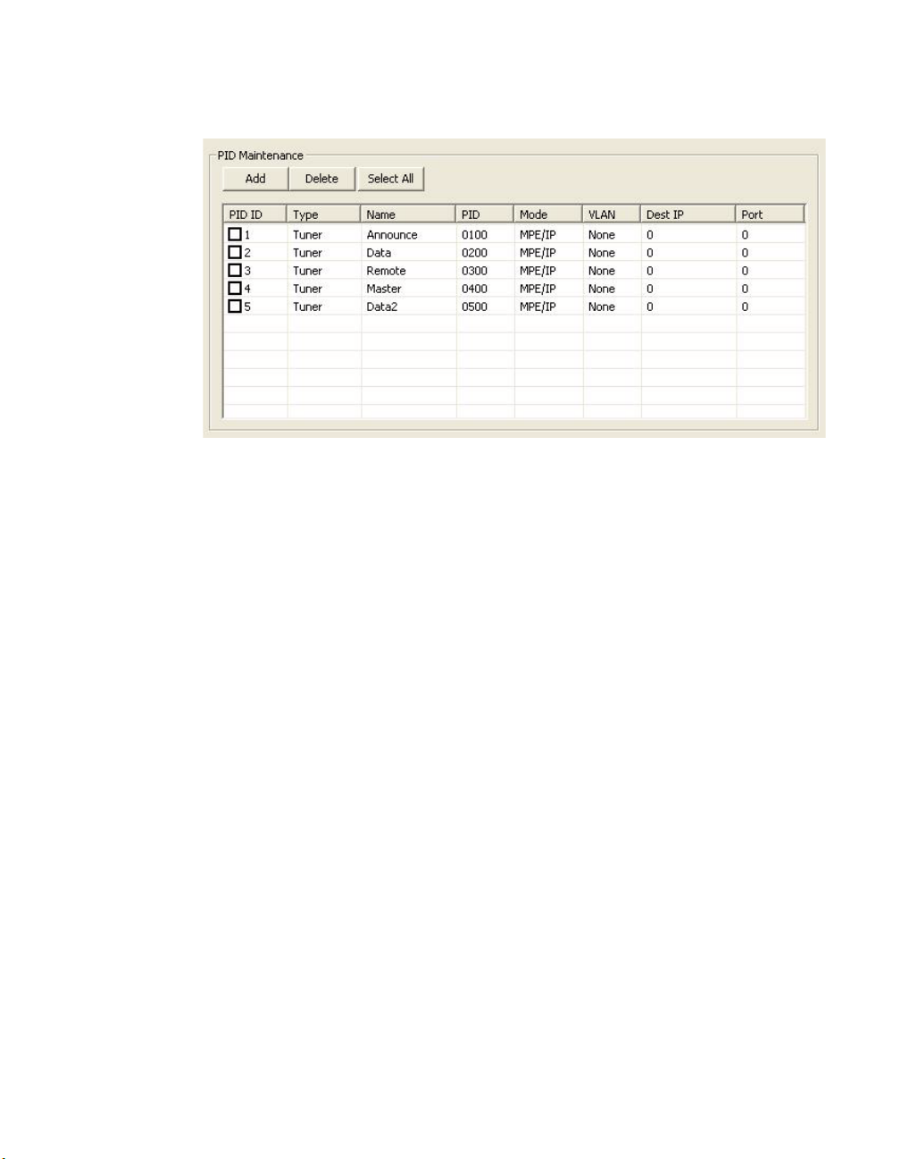
Digicast Media Router Remote Commander
PID Selection
Figure 4-19
PID Maintenance box
Add PID – Allows the user to add a new PID to the PID inventory.
Delete PID – Allows the user to delete a PID from the inventory. This action
only deletes from the listing. This action does not delete the PID on the selected
receivers.
Select All – Allows the user to select or unselect all PIDs for the update.
4-18 VLoad User Guide
Page 89

Adding a PID
Digicast Media Router Remote Commander
Figure 4-20
Digicast Add PID dialog
PID ID – The identifier for the PID on the receiver. The PID ID is the how to
address the PID from this application to the receiver.
PID Name – A user defined identifier.
PID Value – The value of the PID in hexadecimal format.
VLAN ID – Allows the user to set the Virtual Local Area Network ID to one of
the following: None, All, 4094.
Mode – Allows the user to set the Mode to either Multiprotocol Encapsulation /
Internet Protocol(MPE/IP) or Digital Video Broadcasting - Transport Stream
(DVB-TS).
Destination IP Address – The IP address to be used when routing the Transport Stream over the Ethernet IP.
Port – The Port Number used when routing the Transport Stream over the
Ethernet IP.
Chapter 4 - Using VLoad — Digicast Mode 4-19
Page 90

Digicast Media Router Remote Commander
{ This Page is Intentionally Blank }
4-20 VLoad User Guide
Page 91

GLOSSARY
ACK A signal used in computing and other fields to indicate acknowledgement, such
as a packet message used in TCP to acknowledge the receipt of a packet.
ARP Address Resolution Protocol – A protocol for a LAN device to determine the
MAC address of a locally connected device given its IP address. See also MAC.
A
A
PPENDIX
ASR Automatic Switch Request – A switch request message generated by older
Vipersat modems (e.g., CDM-570/L) that is sent to the VMS to establish a new
satellite link or adjust bandwidth between source and destination IP addresses.
B
Base
Modem
BER Bit Error Rate (sometimes Ratio) – A measure of the number of data bits
Appendix A - Glossary A-1
The main component in a satellite communications modem that consistes of a
circuit board with the modem hardware and firmware and the associeated interfaces.
received incorrectly compared to the total number of bits transmitted.
bps bits per second – A measure of the bit rate or transmission speed of a digital
communication link. See also kbps and Mbps.
Page 92

BPSK Binary Phase Shift Keying – Sometimes referred to as 2-PSK. A digital modu-
lation technique in which the carrier is phase shifted +/-180 degrees (two
phases). The simplest and most robust of all PSKs, but unsuitable for high datarate applications when bandwidth is limited due to encoding just one bit per
symbol. See also QPSK and OQPSK.
BUC Block Up Converter – An upconverter so called because it converts a whole
band or “block” of frequencies to a higher band. The IF is converted to final
transmit frequency for satellite communications. The BUC is part of the satellite
ODU/transceiver.
C
C-band A frequency band commonly used for satellite communications (and sometimes
terrestrial microwave). For terrestrial earth stations, the receive frequency band
is 3.7–4.2 GHz and the transmit frequency band is 5.925–6.425 GHz. See also
Ku-band and L-band.
CDD Comtech Data Demodulator
CDM Comtech Data Modem
CIR Committed Information Rate – The guaranteed minimum bandwidth assigned
to a remote terminal.
CLI Character Line Interface – A mechanism for interacting with a computer oper-
ating system or software by typing commands to perform specific tasks.
Codecast A network coding based ad hoc multicast protocol well-suited for multimedia
applications with low-loss, low-latency constraints. Because data is streamed
with no verification, high delivery ratios are obtained with very low overhead.
CRC Cyclic Redundancy Check – A method of applying a checksum to a block of
data to determine if any errors occurred during transmission over communications links.
CXR Carrier – A radio frequency transmission linking points and over which infor-
mation may be carried.
A-2 VLoad User Guide
Page 93

D
DAMA Demand Assigned Multiple Access – A process whereby communications links
are only activated when there is an actual demand.
dBm Decibel referenced to 1 milliwatt.
DES Data Encryption Standard – A federal standard method for encrypting informa-
tion for secure transmission. The Vipersat system offers 3xDES (Triple DES)
for encrypting traffic.
DHCP Dynamic Host Configuration Protocol – An Internet protocol for automating
the configuration of computers that use TCP/IP.
DLL Dynamic Link Library – The implementation of the shared library concept in
the Microsoft Windows system.
Down-
stream
DPC Dynamic Power Control
DSCP Differentiated Services Code Point – The 6-bit field in an IP packet header that
DVB Digital Video Broadcasting – A suite of internationally accepted open standards
DVP Digital Voice Processor – Used in packet voice applications.
In the direction of the network Remote site(s).
is used for packet classification purposes and is the portion of ToS that is
detected by Vipersat modems.
for digital television. DVB-S, DVB-S2, and DVB-RCS are the standards
utilized by satellite services.
E
Eb/N0The ratio of Eb (energy per bit) and N0 (noise power density per Hz). The bit
error rate (BER) for digital data is a decreasing function of this ratio. E
energy of an information bit measured in Joules or, equivalently, in Watts per
Hertz.
is the
b
Appendix A - Glossary A-3
Page 94

F
FAST Code Fully Accessible System Topology Code – Designation for feature code used
by Comtech EF Data for their satellite modems. The FAST method makes it
easy to quickly upgrade the feature options of a modem while it is running live
in the network, either on site or remotely.
FDMA Frequency Division Multiple Access – A technique where multiple users can
access a common resource (e.g. satellite) by each being allocated a distinct
frequency for operation. See also TDMA and STDMA.
FEC Forward Error Correction – A process whereby data being transmitted over a
communications link can have error correction bits added which may be used at
the receiving end to determine/correct any transmission errors which may occur.
Flash Non-volatile computer memory that can be electrically erased and repro-
grammed.
Forward
Path
FTP File Transfer Protocol – An application for transferring computer files over the
Transmission path from the Hub site to a Remote site.
Internet. See also TFTP.
G
G.729 ITU standard for LD-CELP (Low Delay – Code Excited Linear Prediction)
voice encoding at 8 kb/s.
GIR Guaranteed Information Rate
Group ID A number assigned to equipment which defines it as a member of a group when
addressed by the VMS burst controller.
GUI Graphical User Interface – A form of graphical shell or user interface to a
computer operating system or software application.
A-4 VLoad User Guide
Page 95

H
H.323 A protocol standard for multimedia communications designed to support real-
time transfer of audio (such as voice over IP) and video data over packet
networks. Quality of Service is a key feature of H.323. An alternative to SIP.
HDLC High Level Data Link Control – A standard defining how data may be transmit-
ted down a synchronous serial link.
HPA High Power Amplifier – The amplifier used in satellite communications to raise
the transmit signal to the correct power level prior to transmission to satellite.
HTTP Hyper Text Transfer Protocol – The Internet standard for World Wide Web
(WWW) operation.
Hub The central site of a network which links to a number of satellite earth sites
(Remotes).
I
ICMP Internet Control Message Protocol
IDU Indoor Unit – In a VSAT system, the satellite modem is referred to as the IDU.
IF Intermediate Frequency – In satellite systems, IF frequencies are usually
centered around 70/140 MHz (video/TV), or 1200 MHz (L-band).
IFL Intra-Facility Link – The coaxial cabling used to connect the satellite ODU to
the IDU. Carries the inbound and the oubound signals, and the 24 VDC for the
LNB.
Image A binary firmware file that provides the operational code for the processor(s) in
a network unit.
IP Internet Protocol – A format for data packets used on networks accessing the
Internet.
ISP Internet Service Provider – A company providing Internet access.
ITU International Telecommunications Union
Appendix A - Glossary A-5
Page 96

K
kbps kilo bits per second – 1000 bits/second. A measure of the bit rate or transmis-
sion speed of a digital communication link. See also bps and Mbps.
Ku-band A frequency band used for satellite communications. For terrestrial earth
stations, the receive frequency band is in the range 10.95–12.75 GHz and the
transmit frequency band is 13.75–14.5 GHz. See also C-band and L-band.
L
L-band A frequency band commonly used as an IF for satellite systems using block up/
down conversion. Typically 950–1450 MHz Rx, 1250–1750 MHz Tx.
LAN Local Area Network
LLA Low Latency Application
LNA Low Noise Amplifier – An amplifier with very low noise temperature used as
the first amplifier in the receive chain of a satellite system.
LNB Low Noise Block – A downconverter so called because it converts a whole
band or “block” of frequencies to a lower band. The LNB (similar to an LNA) is
part of the satellite ODU/transceiver.
LNC Low Noise Converter – A combined low noise amplifier and block downcon-
verter, typically with an L-band IF.
LO Local Oscillator – A component used in upconverters, downconverters, and
transponders for frequency translation (heterodyne) of the carrier signal.
M
M&C Monitor & Control
MAC Media Access Control – A protocol controlling access to the physical layer of
an Ethernet network.
Mbps Mega bits per second – 1 Million bits/second. A measure of the bit rate or trans-
mission speed of a digital communication link. See also bps and kbps.
Modem Modulator and Demodulator units combined.
A-6 VLoad User Guide
Page 97

Multicast Transmitting a single message simultaneously to multiple destinations (group)
on the IP network.
Multi-
command
A command that allows multiple input choices in a single command execution.
N
NAT Network Address Translation – An Internet standard that enables a LAN to use
one set of IP addresses for internal (private) traffic and a second set of addresses
for external (public) traffic.
NIC Network Interface Controller – The network interface for a PC/workstation that
provides Ethernet connectivity. Depending on the computer, the NIC can either
be built into the motherboard, or be an expansion card. Some computers (e.g.,
servers) have multiple NICs, each indentified by a unique IP address.
NMS Network Management Ssystem
NOC Network Operations Center – The main control center for network operations.
A NOC can interrogate, control, and log network activities for the satellite Hub
as well as any Remote node.
NP Network Processor – Also referred to as the IP Module. An optional assembly
for Comtech EF Data modems that provides the 10/100 BaseT Ethernet interface that is required when used in Vipersat networks.
O
ODU Outdoor Unit – In a VSAT system, the RF components (transceiver) are usually
installed outdoors on the antenna structure itself and are thus referred to as an
ODU. The ODU typically includes the BUC and LNB, and is connected to the
IDU/modem by the IFL cabling.
OQPSK Offset Quadrature Phase Shift Keying – A variant of phase-shift keying using
four different values of the phase to transmit. Offsetting the bit timing limits the
phase shift and yields lower amplitude fluctuations as compared to QPSK, and
is sometimes preferred for communications systems. See also QPSK and BPSK.
OSPF Open Shortest Path First – An open standard interior gateway routing protocol
used to determine the best route for delivering the packets within an IP network.
OSPF routers use the Shortest Path First link state algorithm to calculate the
shortest path to each node in the network. The Vipersat OSPF feature in the
Appendix A - Glossary A-7
Page 98

Comtech SLM-5650A modem/router provides for dynamic routing functionality.
P
PLDM Path Loss Data Message – A packet message that is sent by older Vipersat
modems (e.g., CDM-570/L) to the VMS every sixty seconds, providing status
update and operating parameter information.
PSK Phase Shift Keying – A digital modulation scheme that conveys data by chang-
ing the phase of a base reference signal, the carrier wave. Different PSKs are
used, depending on the data rate required and the signal integrity. Examples are
binary phase-shift keying (BPSK or 2-PSK) which uses two phases, and quadrature phase-shift keying (QPSK or 4-PSK) which uses four phases.
PSTN Public Swithed Telephone Network – The world’s public circuit-switched tele-
phone network, digital and analog, and includes mobile as well as land-line
voice and data communications.
Q
QAM Quadrature Amplitude Modulation – A digital modulation technique in which
the amplitude of two carrier waves is changed to represent the data signal. These
two waves are 90 degrees out of phase with each other.
QoS Quality of Service
QPSK Quadrature Phase Shift Keying – Sometimes referred to as 4-PSK, or 4-QAM.
A modulation technique in which the carrier is phase shifted +/-90 or +/-180
degrees. With four phases, this modulation can encode two bits per symbol—
twice the rate of BPSK. However, it also uses twice the power. See also OQPSK
and BPSK.
R
Remote Satellite earth site that links to a central network site (Hub).
Return Path Transmission path from a Remote site to the Hub site.
A-8 VLoad User Guide
Page 99

RF Radio Frequency – A generic term for signals at frequencies above those used
for baseband or IF.
RFC Request For Comment – The official publication channel for Internet standards
(such as communication protocols) issued by the Internet Engineering Task
Force (IETF).
RIP Routing Information Protocol
ROSS Roaming Oceanic Satellite Server
RS-232 A common electrical/physical standard issued by the IEEE used for point to
point serial communications up to approximately 115 kb/s.
RTP Real-time Transport Protocol – A standardized packet format for delivering
real-time applications such as audio and video over the Internet. Frequently
used in streaming media systems, videoconferencing, and VoIP.
Rx Receive
S
SCPC Single Channel Per Carrier – A satellite communications technique where an
individual channel is transmitted to the designated carrier frequency. Some
applications use SCPC instead of burst transmissions because they require guaranteed, unrestricted bandwidth.
SIP Session Initiation Protocol – A general purpose protocol for multimedia
communications, commonly used for voice over IP (VoIP) signaling. An alternative to the H.323 protocol.
SNG Satellite News Gathering – A satellite uplink van/truck with television crew on
location conducting a live report for a newscast.
SNMP Simple Network Management Protocol – A protocol defining how devices from
different vendors may be managed using a common network management
system.
SOTM Satellite On-The-Move – The ability of a mobile remote terminal to roam
across satellite beams to preserve link integrity and to automatically connect
from one satellite and/or hub to another in a global network.
Star
Topology
STDMA Selective Time Division Multiple Access – A multiple access technique where
Appendix A - Glossary A-9
A network topology which, if drawn as a logical representation, resembles a star
with a hub at the center.
users time-share access to a common channel with variable-sized time slots
allocated on usage.
Page 100

Streamload
Protocol
SUM Status Update Message – A packet message that is sent by newer Vipersat
A proprietary Vipersat data streaming protocol.
modems (e.g., SLM-5650A) to the VMS every sixty seconds, providing status
update and operating parameter information.
T
TCP/IP Transmission Control Protocol / Internet Protocol – A standard for networking
over unreliable transmission paths. See also UDP.
TDM Time Division Multiplexing – A method of multiplexing that provides the
transmission of two or more signals on the same communication path or channel, but at different times by utilizing recurrent timeslots.
TDMA Time Division Multiple Access – A multiple access technique where users
contend for access to a common channel on a time-shared basis. See also FDMA
and STDMA.
TFTP Trivial File Transfer Protocol – A simple file transfer protocol used over reli-
able transmission paths. See also FTP.
ToS Type of Service
Tx Transmit
U
UDP User Datagram Protocol – A standard for networking over reliable transmission
paths.
UDP
Multicast
Unicast Transmitting information/data packets to a single destination on the IP network.
Upstream In the direction of the network Hub site.
A-10 VLoad User Guide
A multicast transmission using the UDP protocol.
 Loading...